
5
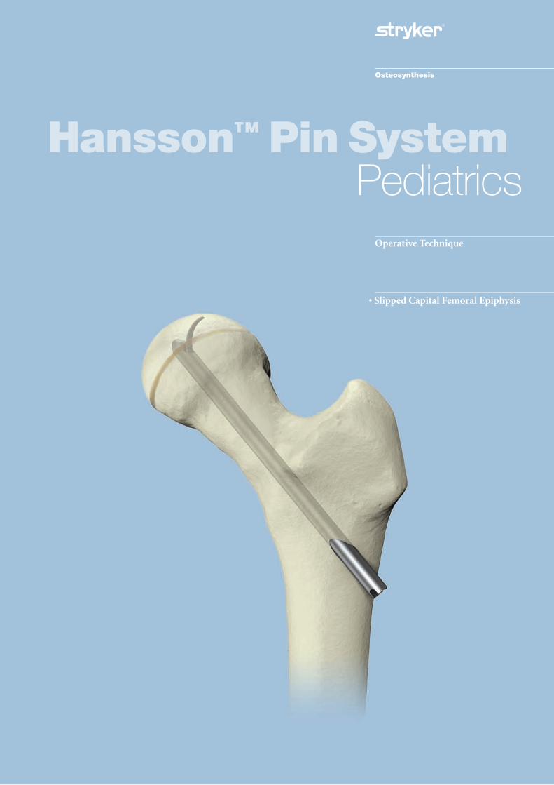
• Slipped Capital Femoral Epiphysis
Operative Technique
Hansson™ Pin SystemPediatrics

2
Contents
Introduction and Rationale 3
Relative Indications & Contraindications 4
Features & Benefits 5
Operative Technique
Patient Positioning 6
Reduction 7
Optional Stabilization Guide Wire Insertion 8
Determining the Incision and Insertion Points 9
Skin Incision and Guide Wire Insertion 10
Drilling and Measurement 11
Instrument-to-Pin Assembly 12
Insertion of the Hansson Pin 13and Activation of the Hook
Instrument Removal 14
Postoperative Regime 15
Pin Removal 16
Ordering Information
Implants 17
Instruments 18
References 19
3
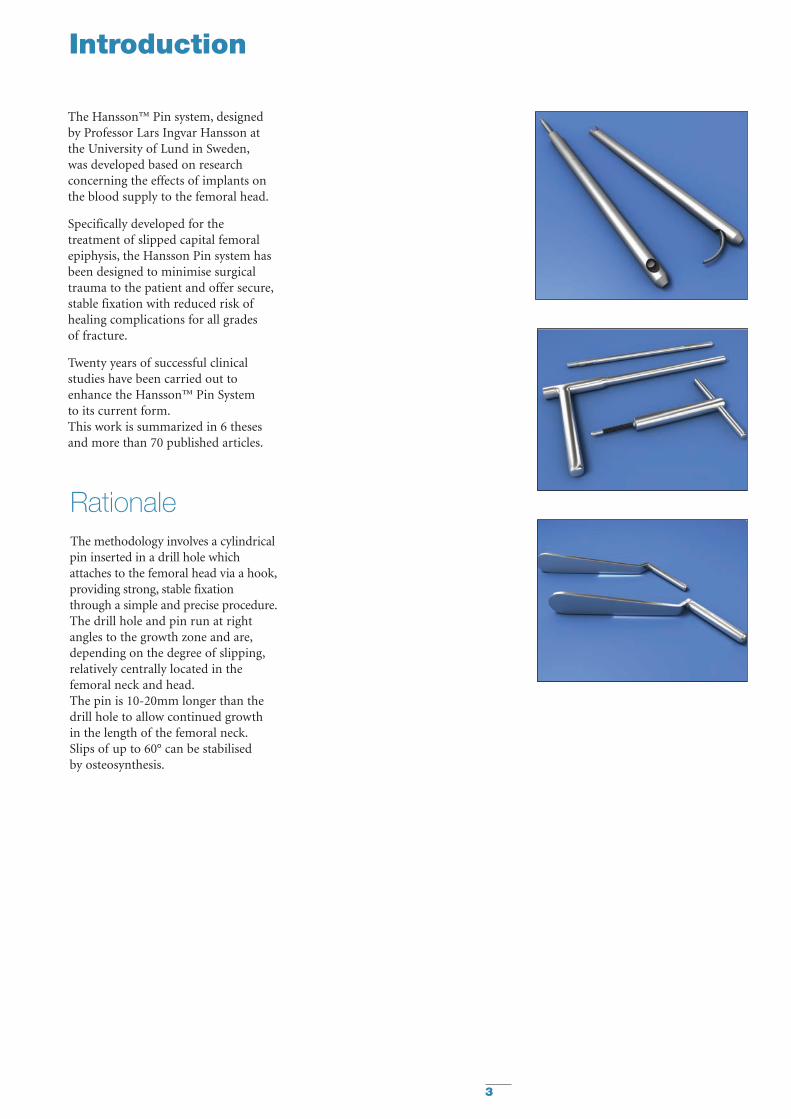
Introduction
The Hansson™ Pin system, designedby Professor Lars Ingvar Hansson atthe University of Lund in Sweden,was developed based on researchconcerning the effects of implants onthe blood supply to the femoral head.
Specifically developed for thetreatment of slipped capital femoralepiphysis, the Hansson Pin system hasbeen designed to minimise surgicaltrauma to the patient and offer secure,stable fixation with reduced risk ofhealing complications for all grades of fracture.
Twenty years of successful clinicalstudies have been carried out toenhance the Hansson™ Pin System to its current form.This work is summarized in 6 thesesand more than 70 published articles.
RationaleThe methodology involves a cylindricalpin inserted in a drill hole whichattaches to the femoral head via a hook,providing strong, stable fixationthrough a simple and precise procedure.The drill hole and pin run at rightangles to the growth zone and are,depending on the degree of slipping,relatively centrally located in thefemoral neck and head.The pin is 10-20mm longer than thedrill hole to allow continued growthin the length of the femoral neck.Slips of up to 60° can be stabilised by osteosynthesis.
4
Relative Indications & Contraindications
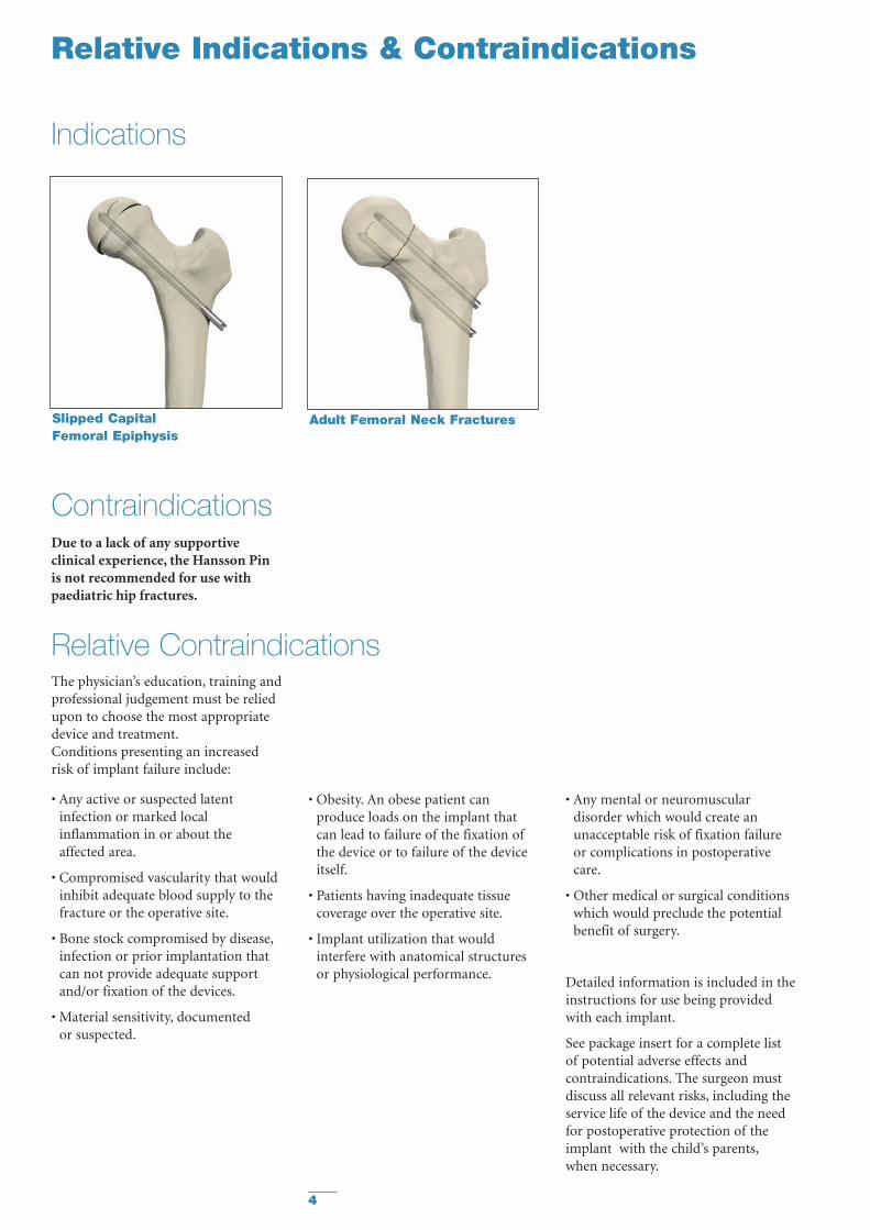
Slipped CapitalFemoral Epiphysis
Adult Femoral Neck Fractures
The physician’s education, training andprofessional judgement must be reliedupon to choose the most appropriatedevice and treatment.Conditions presenting an increasedrisk of implant failure include:
• Any active or suspected latentinfection or marked localinflammation in or about the affected area.
• Compromised vascularity that wouldinhibit adequate blood supply to thefracture or the operative site.
• Bone stock compromised by disease,infection or prior implantation thatcan not provide adequate supportand/or fixation of the devices.
• Material sensitivity, documented or suspected.
• Obesity. An obese patient canproduce loads on the implant thatcan lead to failure of the fixation ofthe device or to failure of the deviceitself.
• Patients having inadequate tissuecoverage over the operative site.
• Implant utilization that wouldinterfere with anatomical structuresor physiological performance.
• Any mental or neuromusculardisorder which would create anunacceptable risk of fixation failureor complications in postoperativecare.
• Other medical or surgical conditionswhich would preclude the potentialbenefit of surgery.
Detailed information is included in theinstructions for use being providedwith each implant.
See package insert for a complete list of potential adverse effects andcontraindications. The surgeon mustdiscuss all relevant risks, including theservice life of the device and the needfor postoperative protection of theimplant with the child’s parents,when necessary.
Relative Contraindications
Contraindications
Indications
Due to a lack of any supportiveclinical experience, the Hansson Pin is not recommended for use withpaediatric hip fractures.
5
Features & Benefits
Preventing diastasis and furtherdisplacement of the epiphysis
The risk of further intraoperativedisplacement of the femoral head isreduced by drilling a channel for theHansson Pin with the femoral headfixed with kirschner wires. The smoothouter pin allows the surgeon to gentlypush the implant through the channel,reducing the risk of diastasis betweenthe femoral neck and the head.1
Lasting stable fixation
The hook resists loosening of thefixation to the femoral head as thelongitudinal growth of the femoralneck retracts the pin in the channelthereby stabilizing the femoral head.Loosening of the implant is potentiallyreduced because of resorption andgrowth of the femoral neck undernormal conditions.1
Reducing the risk of unequalbone length
The continued growth of the femoralneck in cases with Slipped CapitalFemoral Epiphysis is an indication of undisturbed intra- and postoperativevascularization, as the nutrition for theproliferating cells of the growth plate is provided by the epiphysial vessels.By preserving the blood supply,the Hansson Pin System reduces the risk of unequal bone length.1
Easy extraction
The risk of the pin being trapped inthe bone is reduced as the pin surfaceis smooth. The hook is easilywithdrawn back into the body of thepin, which can then be removed.1
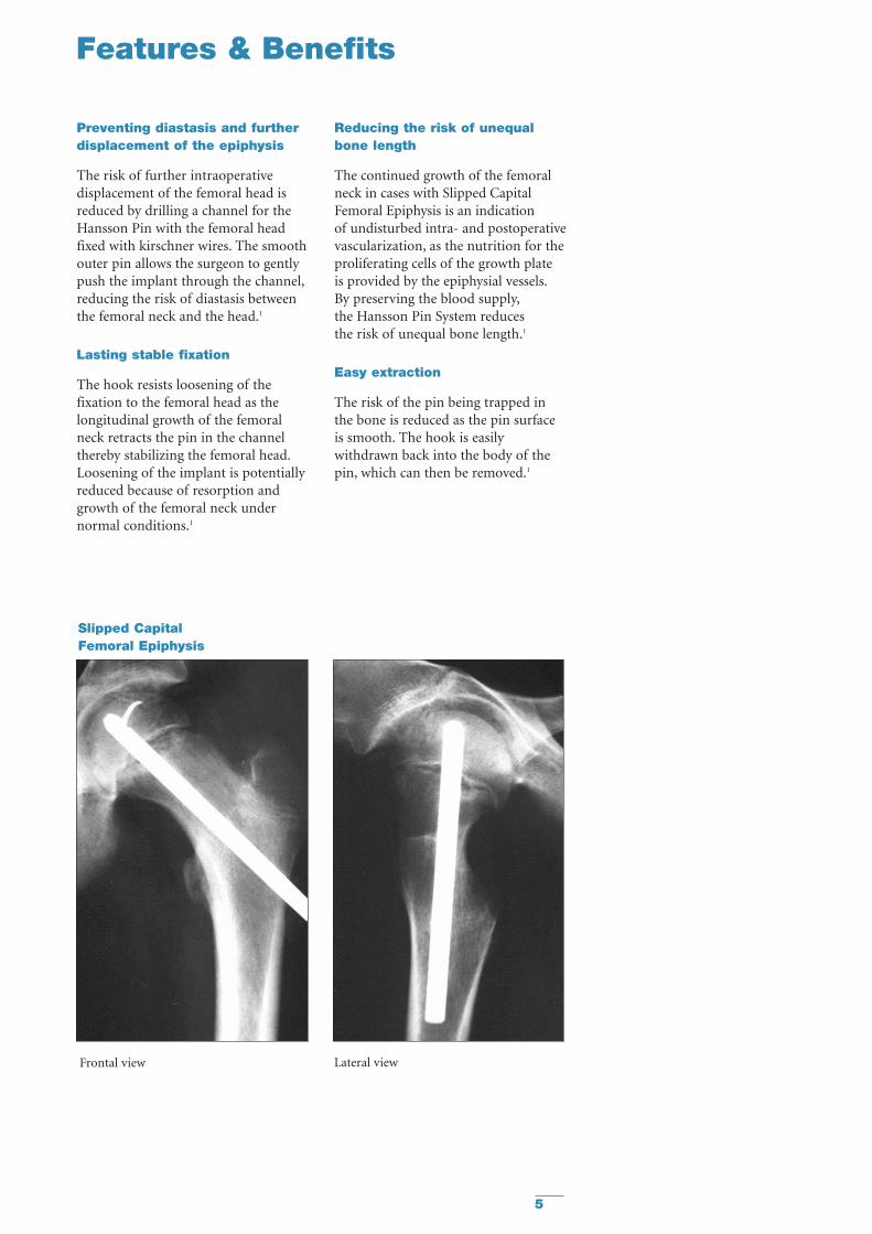
Frontal view Lateral view
Slipped CapitalFemoral Epiphysis
6
Operative Technique
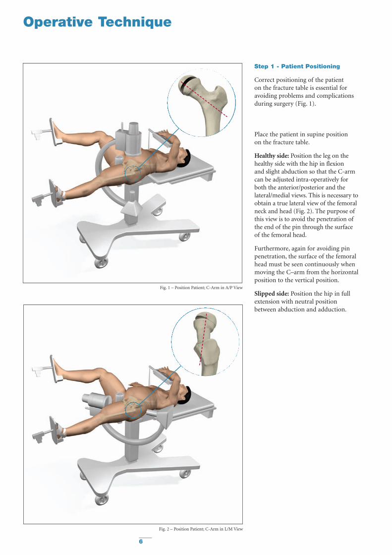
Step 1 - Patient Positioning
Correct positioning of the patient on the fracture table is essential foravoiding problems and complicationsduring surgery (Fig. 1).
Place the patient in supine position on the fracture table.
Healthy side: Position the leg on thehealthy side with the hip in flexion and slight abduction so that the C-armcan be adjusted intra-operatively forboth the anterior/posterior and thelateral/medial views. This is necessary toobtain a true lateral view of the femoralneck and head (Fig. 2). The purpose ofthis view is to avoid the penetration ofthe end of the pin through the surfaceof the femoral head.
Furthermore, again for avoiding pinpenetration, the surface of the femoralhead must be seen continuously whenmoving the C–arm from the horizontalposition to the vertical position.
Slipped side: Position the hip in fullextension with neutral positionbetween abduction and adduction.
Fig. 1 – Position Patient; C-Arm in A/P View
Fig. 2 – Position Patient; C-Arm in L/M View
7
Operative Technique
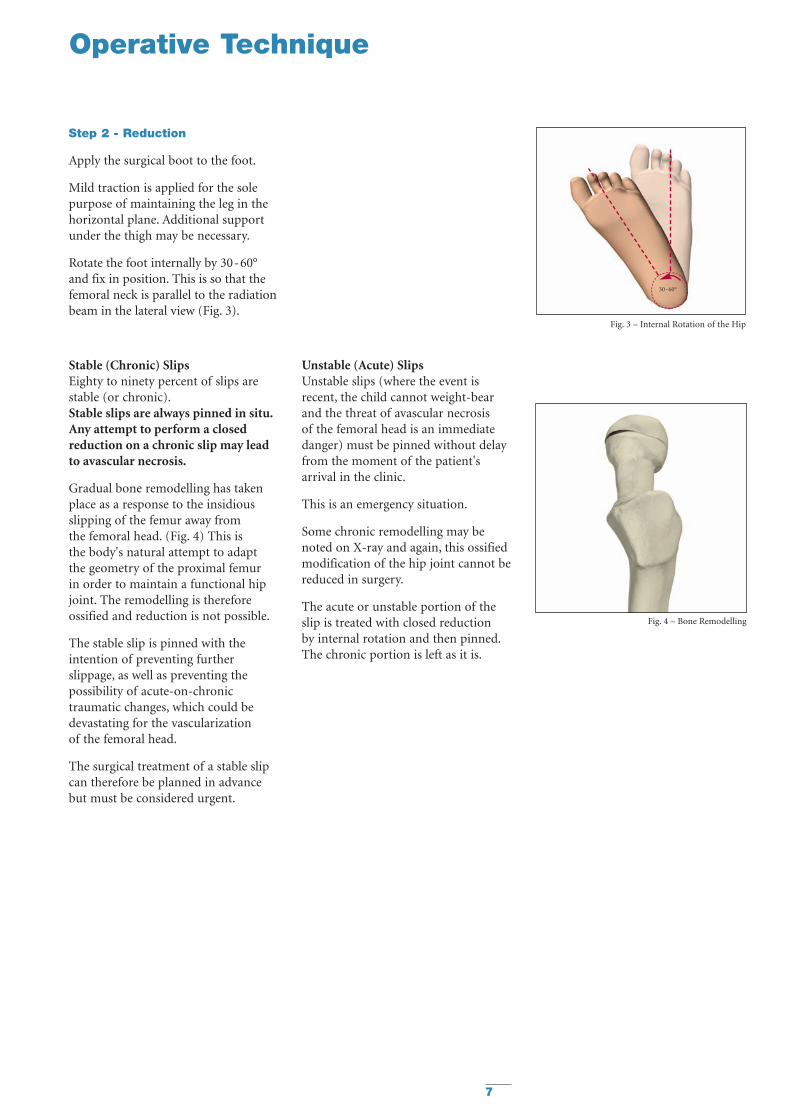
Step 2 - Reduction
Apply the surgical boot to the foot.
Mild traction is applied for the solepurpose of maintaining the leg in thehorizontal plane. Additional supportunder the thigh may be necessary.
Rotate the foot internally by 30-60°and fix in position. This is so that thefemoral neck is parallel to the radiationbeam in the lateral view (Fig. 3).
Stable (Chronic) SlipsEighty to ninety percent of slips arestable (or chronic).Stable slips are always pinned in situ.Any attempt to perform a closedreduction on a chronic slip may leadto avascular necrosis.
Gradual bone remodelling has takenplace as a response to the insidiousslipping of the femur away from the femoral head. (Fig. 4) This is the body's natural attempt to adapt the geometry of the proximal femur in order to maintain a functional hipjoint. The remodelling is thereforeossified and reduction is not possible.
The stable slip is pinned with theintention of preventing furtherslippage, as well as preventing thepossibility of acute-on-chronictraumatic changes, which could bedevastating for the vascularization of the femoral head.
The surgical treatment of a stable slipcan therefore be planned in advancebut must be considered urgent.
Fig. 3 – Internal Rotation of the Hip
Fig. 4 – Bone Remodelling
30-60°
Unstable (Acute) SlipsUnstable slips (where the event isrecent, the child cannot weight-bearand the threat of avascular necrosis of the femoral head is an immediatedanger) must be pinned without delayfrom the moment of the patient'sarrival in the clinic.
This is an emergency situation.
Some chronic remodelling may benoted on X-ray and again, this ossifiedmodification of the hip joint cannot bereduced in surgery.
The acute or unstable portion of theslip is treated with closed reduction by internal rotation and then pinned.The chronic portion is left as it is.
8
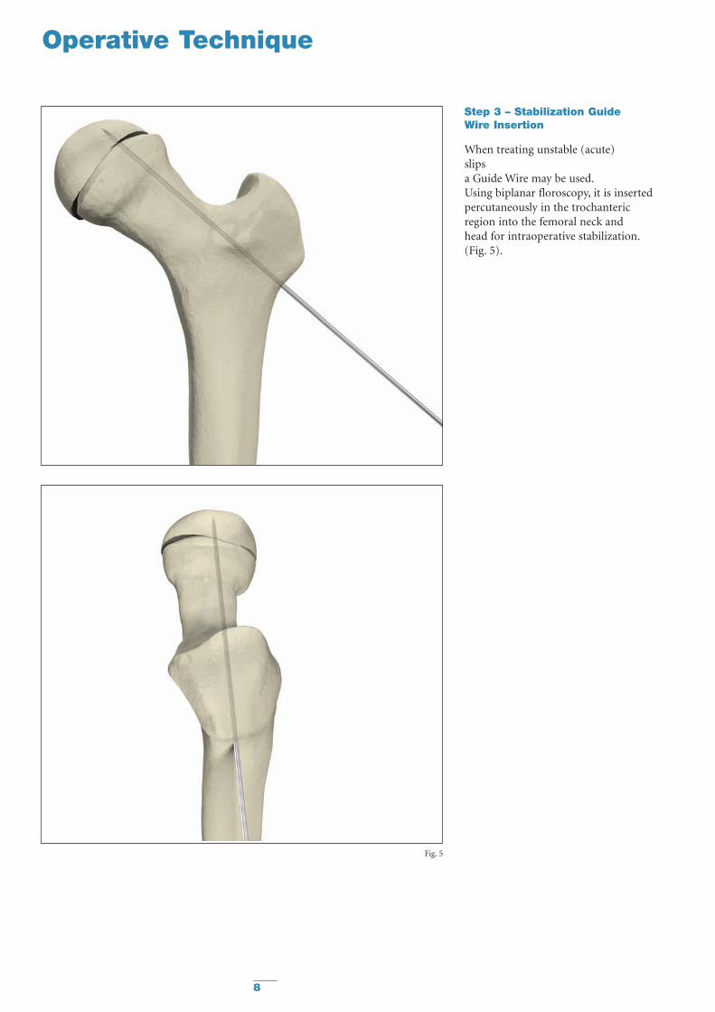
Step 3 – Stabilization Guide Wire Insertion
When treating unstable (acute) slips a Guide Wire may be used.Using biplanar floroscopy, it is insertedpercutaneously in the trochantericregion into the femoral neck and head for intraoperative stabilization.(Fig. 5).
Fig. 5
Operative Technique
9
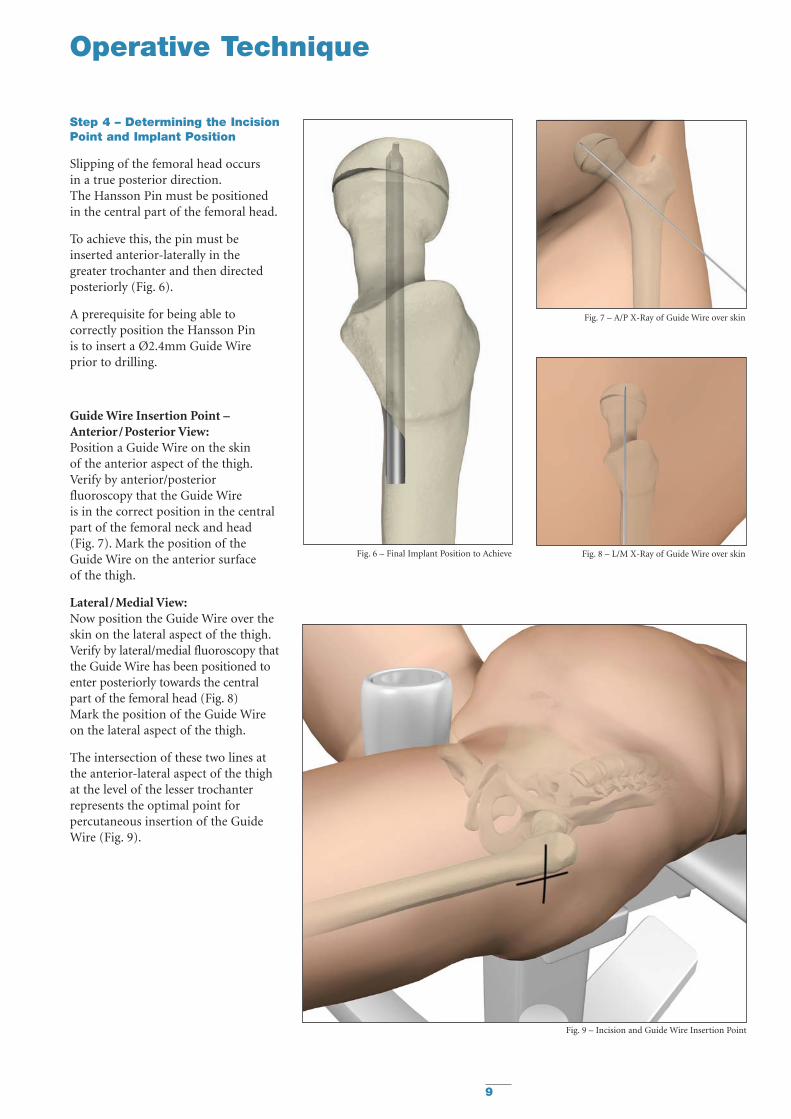
Step 4 – Determining the IncisionPoint and Implant Position
Slipping of the femoral head occurs in a true posterior direction.The Hansson Pin must be positionedin the central part of the femoral head.
To achieve this, the pin must beinserted anterior-laterally in thegreater trochanter and then directedposteriorly (Fig. 6).
A prerequisite for being able tocorrectly position the Hansson Pin is to insert a Ø2.4mm Guide Wireprior to drilling.
Guide Wire Insertion Point –Anterior/Posterior View:Position a Guide Wire on the skin of the anterior aspect of the thigh.Verify by anterior/posteriorfluoroscopy that the Guide Wire is in the correct position in the centralpart of the femoral neck and head(Fig. 7). Mark the position of theGuide Wire on the anterior surface of the thigh.
Lateral/Medial View:Now position the Guide Wire over theskin on the lateral aspect of the thigh.Verify by lateral/medial fluoroscopy thatthe Guide Wire has been positioned toenter posteriorly towards the centralpart of the femoral head (Fig. 8) Mark the position of the Guide Wireon the lateral aspect of the thigh.
The intersection of these two lines atthe anterior-lateral aspect of the thighat the level of the lesser trochanterrepresents the optimal point forpercutaneous insertion of the GuideWire (Fig. 9).
Fig. 6 – Final Implant Position to Achieve Fig. 8 – L/M X-Ray of Guide Wire over skin
Fig. 7 – A/P X-Ray of Guide Wire over skin
Fig. 9 – Incision and Guide Wire Insertion Point
Operative Technique
10
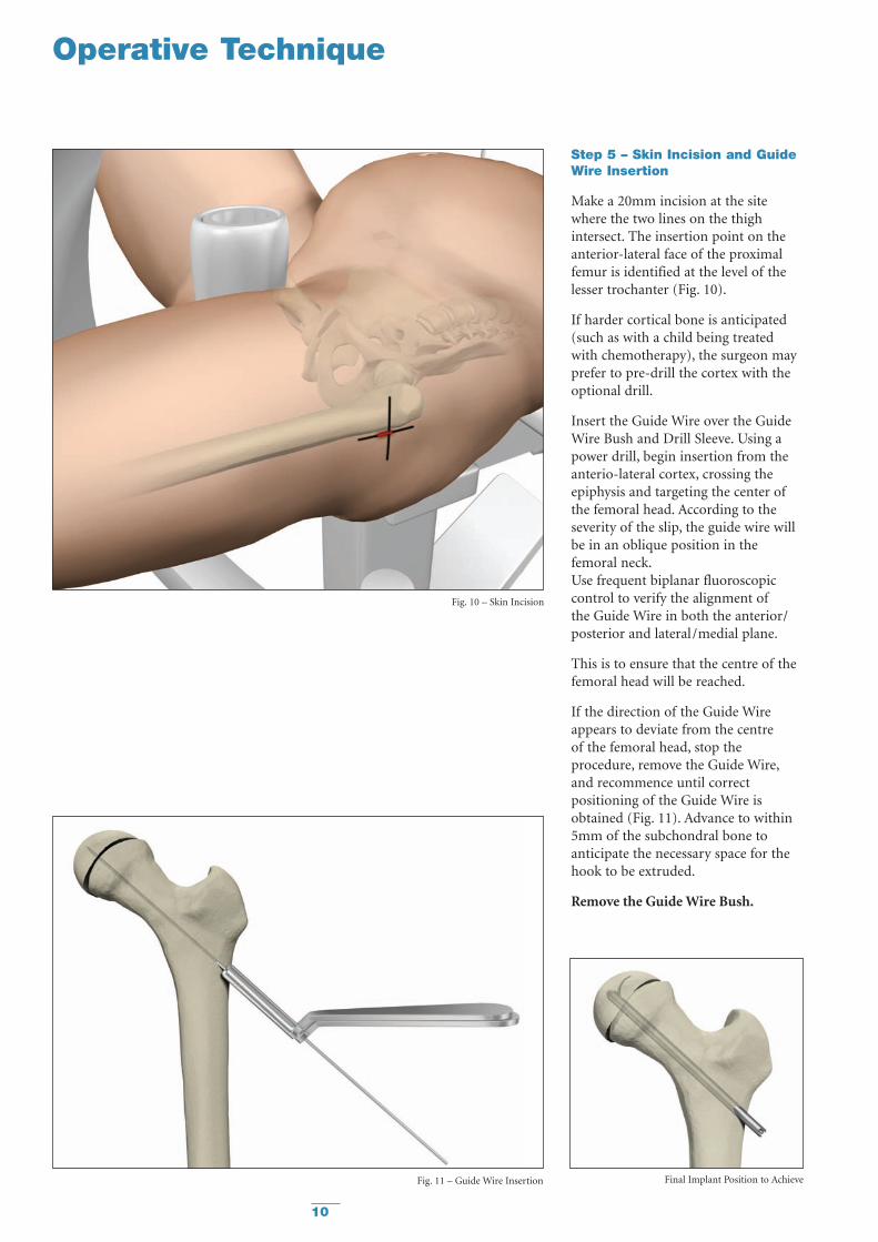
Step 5 – Skin Incision and GuideWire Insertion
Make a 20mm incision at the sitewhere the two lines on the thighintersect. The insertion point on theanterior-lateral face of the proximalfemur is identified at the level of thelesser trochanter (Fig. 10).
If harder cortical bone is anticipated(such as with a child being treated with chemotherapy), the surgeon mayprefer to pre-drill the cortex with theoptional drill.
Insert the Guide Wire over the GuideWire Bush and Drill Sleeve. Using apower drill, begin insertion from theanterio-lateral cortex, crossing theepiphysis and targeting the center ofthe femoral head. According to theseverity of the slip, the guide wire willbe in an oblique position in thefemoral neck.Use frequent biplanar fluoroscopiccontrol to verify the alignment ofthe Guide Wire in both the anterior/posterior and lateral/medial plane.
This is to ensure that the centre of thefemoral head will be reached.
If the direction of the Guide Wireappears to deviate from the centre of the femoral head, stop theprocedure, remove the Guide Wire,and recommence until correctpositioning of the Guide Wire isobtained (Fig. 11). Advance to within5mm of the subchondral bone toanticipate the necessary space for thehook to be extruded.
Remove the Guide Wire Bush.
Fig. 10 – Skin Incision
Operative Technique
Fig. 11 – Guide Wire Insertion Final Implant Position to Achieve
11
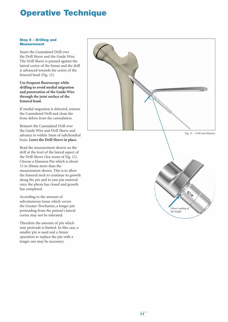
Step 6 – Drilling andMeasurement
Insert the Cannulated Drill over the Drill Sleeve and the Guide Wire.The Drill Sleeve is pressed against thelateral cortex of the femur and the drillis advanced towards the centre of thefemoral head (Fig. 12).
Use frequent fluoroscopy whiledrilling to avoid medial migrationand penetration of the Guide Wirethrough the joint surface of thefemoral head.
If medial migration is detected, removethe Cannulated Drill and clean thebone debris from the cannulation.
Reinsert the Cannulated Drill over the Guide Wire and Drill Sleeve andadvance to within 5mm of subchondralbone. Leave the Drill Sleeve in place.
Read the measurement shown on thedrill at the level of the lateral aspect ofthe Drill Sleeve (See zoom of Fig. 12).Choose a Hansson Pin which is about 15 to 20mm more than themeasurement shown. This is to allowthe femoral neck to continue its growthalong the pin and to ease pin removalonce the physis has closed and growthhas completed.
According to the amount ofsubcutaneous tissue which covers the Greater Trochanter, a longer pinprotruding from the patient's lateralcortex may not be tolerated.
Therefore the amount of pin whichmay protrude is limited. In this case, asmaller pin is used and a futureoperation to replace the pin with alonger one may be necessary.
Operative Technique
Fig. 12 – Drill and Measure
Direct reading ofthe length
12
Operative Technique
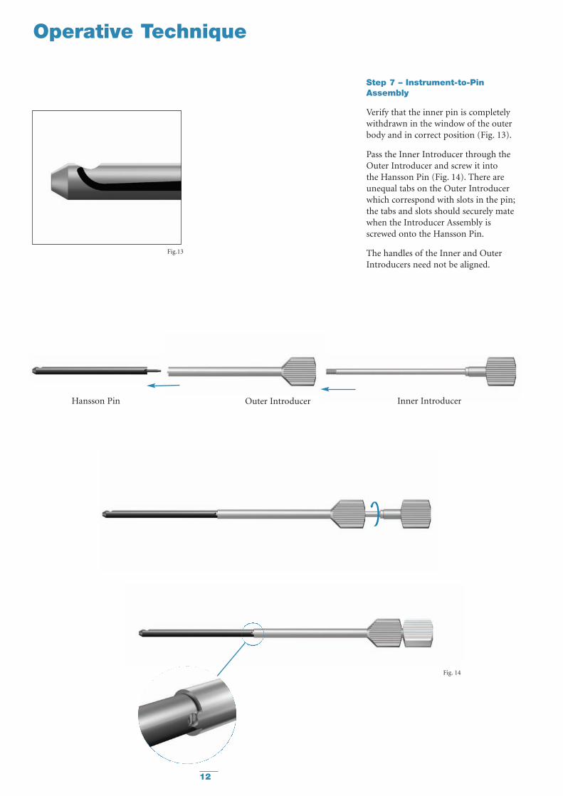
Step 7 – Instrument-to-PinAssembly
Verify that the inner pin is completelywithdrawn in the window of the outerbody and in correct position (Fig. 13).
Pass the Inner Introducer through theOuter Introducer and screw it into the Hansson Pin (Fig. 14). There areunequal tabs on the Outer Introducerwhich correspond with slots in the pin;the tabs and slots should securely matewhen the Introducer Assembly isscrewed onto the Hansson Pin.
The handles of the Inner and OuterIntroducers need not be aligned.
Fig.13
Fig. 14
Hansson Pin Outer Introducer Inner Introducer
13
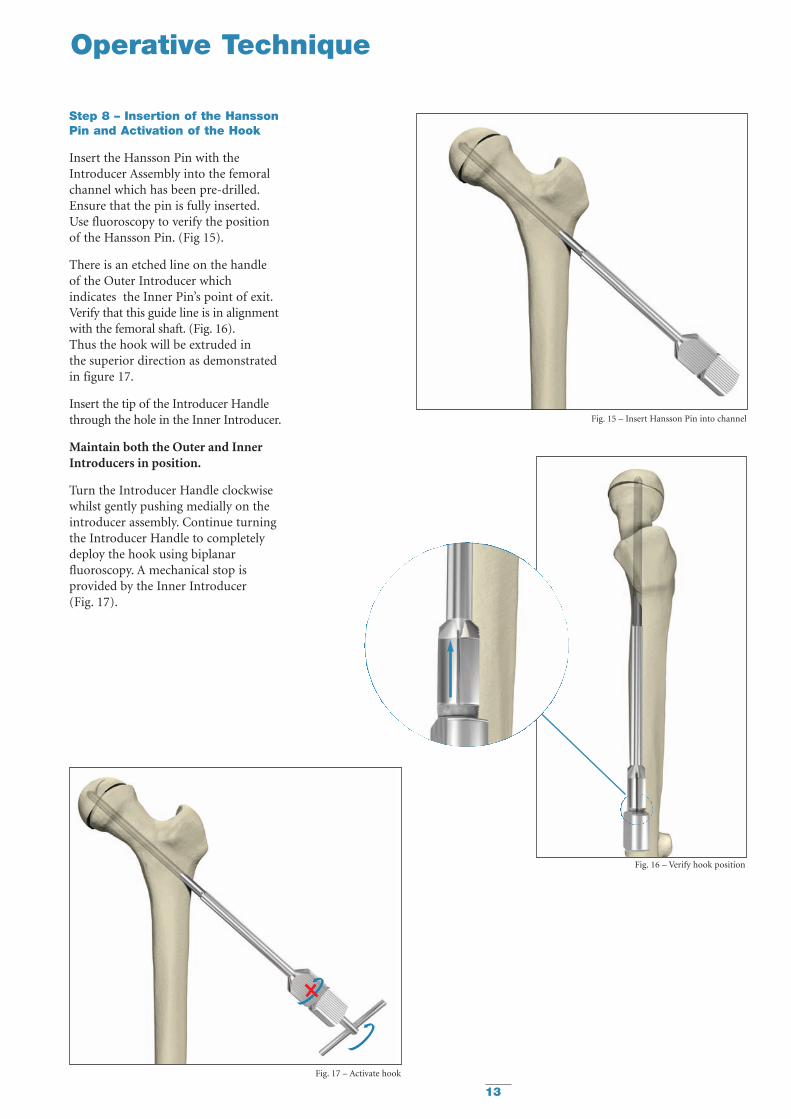
Step 8 – Insertion of the HanssonPin and Activation of the Hook
Insert the Hansson Pin with theIntroducer Assembly into the femoralchannel which has been pre-drilled.Ensure that the pin is fully inserted.Use fluoroscopy to verify the positionof the Hansson Pin. (Fig 15).
There is an etched line on the handle of the Outer Introducer whichindicates the Inner Pin’s point of exit.Verify that this guide line is in alignmentwith the femoral shaft. (Fig. 16).Thus the hook will be extruded in the superior direction as demonstratedin figure 17.
Insert the tip of the Introducer Handlethrough the hole in the Inner Introducer.
Maintain both the Outer and InnerIntroducers in position.
Turn the Introducer Handle clockwisewhilst gently pushing medially on theintroducer assembly. Continue turningthe Introducer Handle to completelydeploy the hook using biplanarfluoroscopy. A mechanical stop isprovided by the Inner Introducer (Fig. 17).
Operative Technique
Fig. 15 – Insert Hansson Pin into channel
Fig. 16 – Verify hook position
Fig. 17 – Activate hook
14
Operative Technique
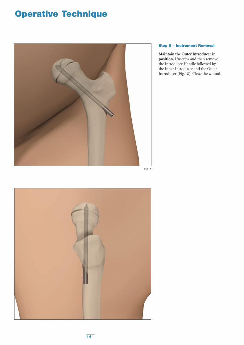
Step 9 – Instrument Removal
Maintain the Outer Introducer inposition. Unscrew and then remove the Introducer Handle followed by the Inner Introducer and the OuterIntroducer (Fig.18). Close the wound.
Fig.18
15
Postoperative Regime
Stable Slip:
The patient is allowed to start walkingusing crutches and partial weightbearing on the operated side the firstday after surgery.Usually the patient can be dischargedfrom the ward one to two days aftersurgery when he or she is capable ofwalking with crutches.Full weight bearing is possible after one week.
Unstable Slip:
The patient is allowed to start walkingusing crutches and partial weightbearing on the operated side the firstday after surgery.Full weight bearing on the operated legis not allowed until after six weeks.
Postoperative Activities - Stable and Unstable:
Surgeons should instruct parentsregarding appropriate and restrictedactivities during the treatment in orderto prevent placing excessive stress on the implants which may lead to fixation or implant failure andaccompanying clinical problems.
Surgeons should also instruct parentsto report any unusual changes of theoperative site to his/her physician.
The physician should closely monitorthe patient if a change at the site hasbeen detected.
Bilateral Slips:
Periodic X-Ray images should be takenof both hips to facilitate early detectionof contralateral slips.
Follow Up Examination – Stable and Unstable:
A six-week post-op follow up medicaland radiological examination isrecommended.
When assessing the follow-up X-ray,the surgeon must look for:
• Reliable anchorage of the hook in thefemoral head.
• Protrusion of the end of the pinthrough the lateral cortex of thethigh.
The most accurate angle to view theprotrusion of the pin is the lateralposition, due to the insertion angle.
If the X-rays are satisfactory, thenwalking is permitted.
Repeat X-rays are necessary every 6months until the physes have closed.
16
Operative Technique
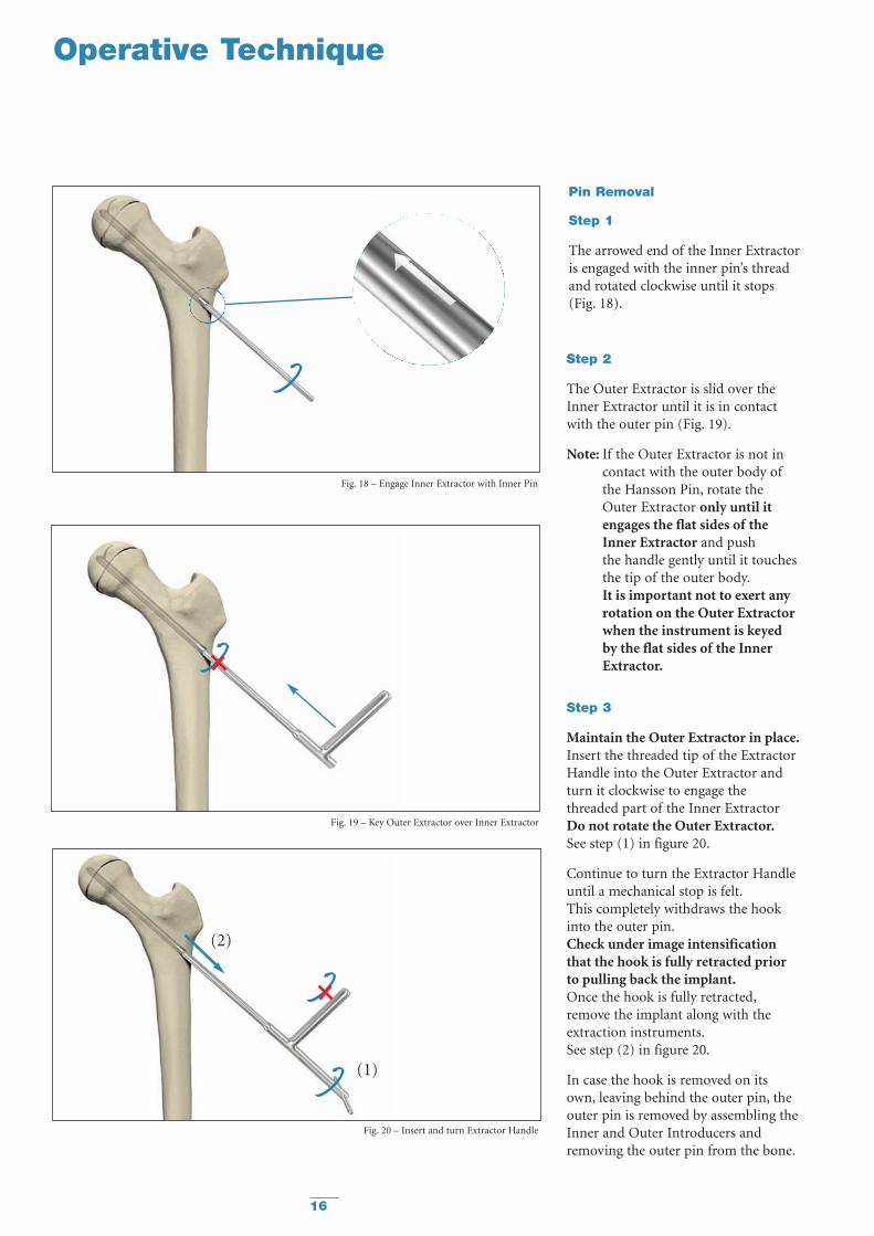
Pin Removal
Step 1
The arrowed end of the Inner Extractoris engaged with the inner pin’s threadand rotated clockwise until it stops (Fig. 18).
Step 2
The Outer Extractor is slid over theInner Extractor until it is in contactwith the outer pin (Fig. 19).
Note: If the Outer Extractor is not incontact with the outer body ofthe Hansson Pin, rotate theOuter Extractor only until itengages the flat sides of the Inner Extractor and push the handle gently until it touchesthe tip of the outer body.It is important not to exert anyrotation on the Outer Extractorwhen the instrument is keyedby the flat sides of the InnerExtractor.
Step 3
Maintain the Outer Extractor in place.Insert the threaded tip of the ExtractorHandle into the Outer Extractor andturn it clockwise to engage thethreaded part of the Inner ExtractorDo not rotate the Outer Extractor.See step (1) in figure 20.
Continue to turn the Extractor Handleuntil a mechanical stop is felt.This completely withdraws the hookinto the outer pin.Check under image intensificationthat the hook is fully retracted priorto pulling back the implant.Once the hook is fully retracted,remove the implant along with theextraction instruments.See step (2) in figure 20.
In case the hook is removed on itsown, leaving behind the outer pin, theouter pin is removed by assembling theInner and Outer Introducers andremoving the outer pin from the bone.
Fig. 18 – Engage Inner Extractor with Inner Pin
Fig. 19 – Key Outer Extractor over Inner Extractor
Fig. 20 – Insert and turn Extractor Handle
(1)
(2)
17
Ordering Information — Implants
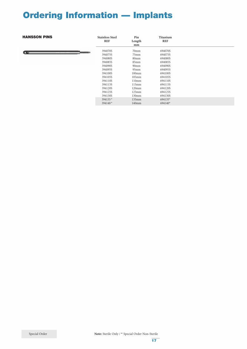
Stainless Steel Pin TitaniumREF Length REF
mm
394070S 70mm 694070S394075S 75mm 694075S394080S 80mm 694080S394085S 85mm 694085S394090S 90mm 694090S394095S 95mm 694095S394100S 100mm 694100S394105S 105mm 694105S394110S 110mm 694110S394115S 115mm 694115S394120S 120mm 694120S394125S 125mm 694125S394130S 130mm 694130S394135 * 135mm 694135*394140 * 140mm 694140*
HANSSON PINS
Special Order Note: Sterile Only / * Special Order Non-Sterile
18
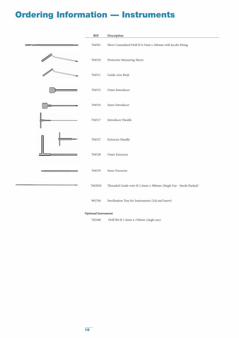
Ordering Information — Instruments
REF Description
704501 Short Cannulated Drill Ø 6.7mm x 246mm with Jacobs fitting
704510 Protective Measuring Sleeve
704511 Guide-wire Bush
704515 Outer Introducer
704516 Inner Introducer
704517 Introducer Handle
704527 Extractor Handle
704528 Outer Extractor
704529 Inner Extractor
704505S Threaded Guide-wire Ø 2.4mm x 300mm (Single Use - Sterile Packed)
901704 Sterilisation Tray for Instruments (Lid and Insert)
Optional Instrument
702448 Drill Bit Ø 1.4mm x 150mm (single use).
19
References
References:
1. Hansson L.I. (1982): Osteosynthesiswith the Hook-Pin in Slipped CapitalFemoral Epiphysis. Acta Orthop. Scand.53: 87-96
2. Slipped Capital Femoral EpiphysisJournal of Pediatric Orthopaedics.26(3):286-290, May/June 2006.Lehmann, Charles L. BS *; Arons,Raymond R. PhD +; Loder, Randall T.MD ++; Vitale, Michael G. MD, MPH +[S]
3. Bone Growth After Fixing SlippedFemoral Epiphysis: Brief ReportJ Bone Joint Surg (Br) 1988 ;70-B : 846-6.Hägglund, Gunnar ; Bylander, Birger ;Hansson, Lars Ingvar ; Selvik, Göran.
4. Radiographic Assessment ofCoxarthrosis Following Slipped CapitalFemoral Epipysis, A 32-year follow-upstudy of 51 hips.Acta Radiologica 34 (1993) Fasc. 2Hansson, G.; Jerre, R.; Sanders, S.M.;Wallin, J.
5. The Contralateral Hip in PatientsPrimarily Treated for Unilateral SlippedUpper Femoral Epiphysis, a long-termfollow-up of 61 hipsJ Bone Joint Surgery (Br) 1994; 76-B:563-7.Jerre, Ragnar; Billing, Lars; Hansson,Göran; Wallin, Jan
6. Long-term Results After Nailing in situof Slipped Upper Femoral EpiphysisA 30-year follow-up of 59 hips.The Journal of Bone and Joint Surgery(Br) 1998;80-B:70-7Hansson, G; Billing, B.; Högstedt, B.;Jerre, R.; Wallin, J.
7. Prophylactic Pinning of theContralateral Hip in Slipped CapitalFemoral EpiphysisEvaluation of Long-Term Outcome for the Contralateral Hip with Use of Decision AnalysisJournal of Bone and Joint Surgery, Inc.2002W. Randall Schultz, MD, MS, James N.Weinstein, DO, MS, Stuart L. Weinstein,MD and Brian G. Smith, MD
8. The Epidemiology of Slipped CapitalFemoral Epiphysis: An UpdatePaper No: 050 Presented at the AmericanAcademy of Orthopaedic Surgeons2005 Annual Meeting, Washington, DC –February 23, 2005Michael G Vitale, MD; Charles LehmannBS; Randall T Loder, MD
9. Osteosynthesis with the Hook-Pin inSlipped Capital Femoral Epiphysis,Hansson, L.I. (1982):Acta Orthop. Scand. 53: 87-96
10. Vitality of the Slipped CapitalFemoral Epiphysis. Preoperativeevaluation by tetracycline labeling.Hagglund, G., Hansson, L.I. andOrdeberg G. (1985).
Thesis:
1. Physiolysis of the Hip. Epidemiology,natural history and long time resultsafter closed treatment.Gunnar Ordeberg, 1986.
2. Physiolysis of the Hip. Epidemiology,etiology and therapy.Gunnar Hägglund, 1986.

Stryker Trauma AGBohnackerweg 1CH-2545 SelzachSwitzerland
www.osteosynthesis.stryker.com
The information presented in this brochure is intended to demonstrate a Stryker product. Always refer to the packageinsert, product label and/or user instructions before using any Stryker product. Surgeons must always rely on their ownclinical judgment when deciding which products and techniques to use with their patients. Products may not be availablein all markets. Product availability is subject to the regulatory or medical practices that govern individual markets. Pleasecontact your Stryker representative if you have questions about the availability of Stryker products in your area.
Stryker Corporation or its subsidiary owns the registered trademark: Stryker.Swemac Orthopaedics AB owns the following trademark: Hansson Pin.
Literature Number: 982303LOT A2806
US Patents pending
Copyright © 2006 StrykerPrinted in Switzerland


