

Steam Locomotives
Heritage Engines
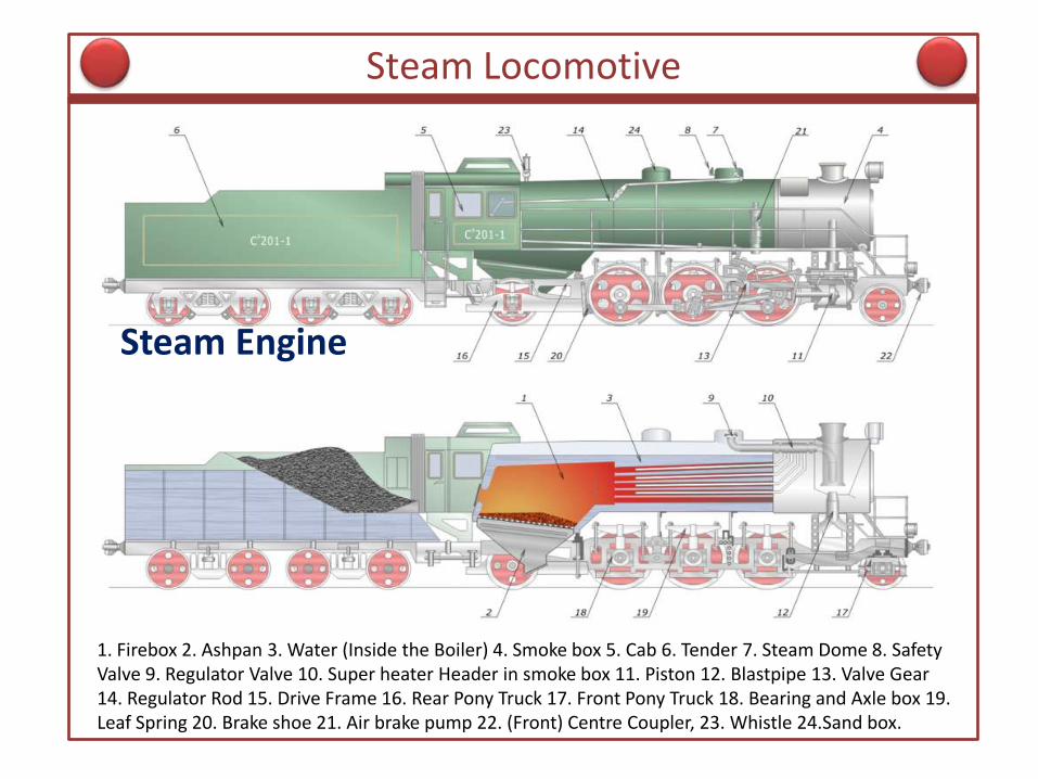
Steam Locomotive
1. Firebox 2. Ashpan 3. Water (Inside the Boiler) 4. Smoke box 5. Cab 6. Tender 7. Steam Dome 8. Safety Valve 9. Regulator Valve 10. Super heater Header in smoke box 11. Piston 12. Blastpipe 13. Valve Gear 14. Regulator Rod 15. Drive Frame 16. Rear Pony Truck 17. Front Pony Truck 18. Bearing and Axle box 19. Leaf Spring 20. Brake shoe 21. Air brake pump 22. (Front) Centre Coupler, 23. Whistle 24.Sand box.
Steam Engine

Steam Engines
1. Reciprocating positive
displacement machine
2. External combustion engine
only {furnace in boiler}
3. Lumped coal fuelled
horizontal fire tube boilers
4. Exhaust Steam compression
by spool valve in double acting
steam cylinder towards every
piston stroke only thereby eating
modified Rankine Cycle Power

Locomotive Boiler side section
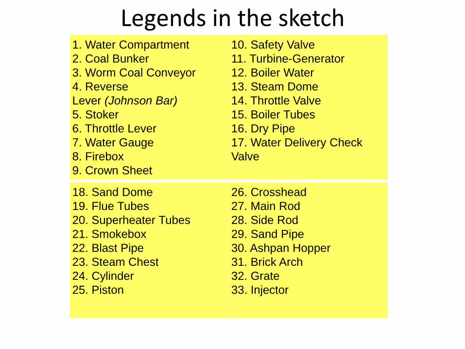
Legends in the sketch 1. Water Compartment
2. Coal Bunker
3. Worm Coal Conveyor
4. Reverse
Lever (Johnson Bar)
5. Stoker
6. Throttle Lever
7. Water Gauge
8. Firebox
9. Crown Sheet
10. Safety Valve
11. Turbine-Generator
12. Boiler Water
13. Steam Dome
14. Throttle Valve
15. Boiler Tubes
16. Dry Pipe
17. Water Delivery Check
Valve
18. Sand Dome
19. Flue Tubes
20. Superheater Tubes
21. Smokebox
22. Blast Pipe
23. Steam Chest
24. Cylinder
25. Piston
26. Crosshead
27. Main Rod
28. Side Rod
29. Sand Pipe
30. Ashpan Hopper
31. Brick Arch
32. Grate
33. Injector

Wheelset Counterbalancing

Indicator diagram

Valvegear components

Legends in the Sketch 1. Eccentric Crank 2. Eccentric Rod 3. Reach Rod 4. Lifting Link 5. Lifting Arm 6. Reverse Arm & Shaft 7. Link (Expansion Link) 8. Radius Bar 9. Crosshead Arm 10. Valve Stem Guide 11. Union Link 12. Combination Lever 13. Valve Stem 14. Valve Spindle

Walschaertz Valvegear mechanism

Walschaertz Valvegear reversing
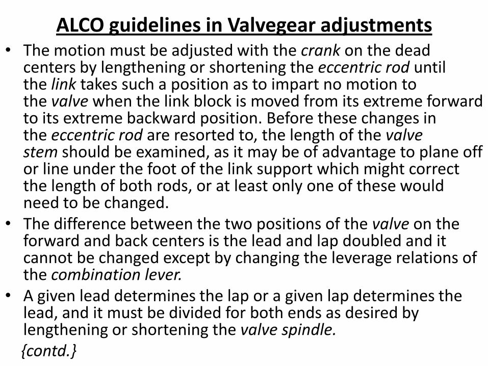
ALCO guidelines in Valvegear adjustments • The motion must be adjusted with the crank on the dead
centers by lengthening or shortening the eccentric rod until the link takes such a position as to impart no motion to the valve when the link block is moved from its extreme forward to its extreme backward position. Before these changes in the eccentric rod are resorted to, the length of the valve stem should be examined, as it may be of advantage to plane off or line under the foot of the link support which might correct the length of both rods, or at least only one of these would need to be changed.
• The difference between the two positions of the valve on the forward and back centers is the lead and lap doubled and it cannot be changed except by changing the leverage relations of the combination lever.
• A given lead determines the lap or a given lap determines the lead, and it must be divided for both ends as desired by lengthening or shortening the valve spindle.
{contd.}
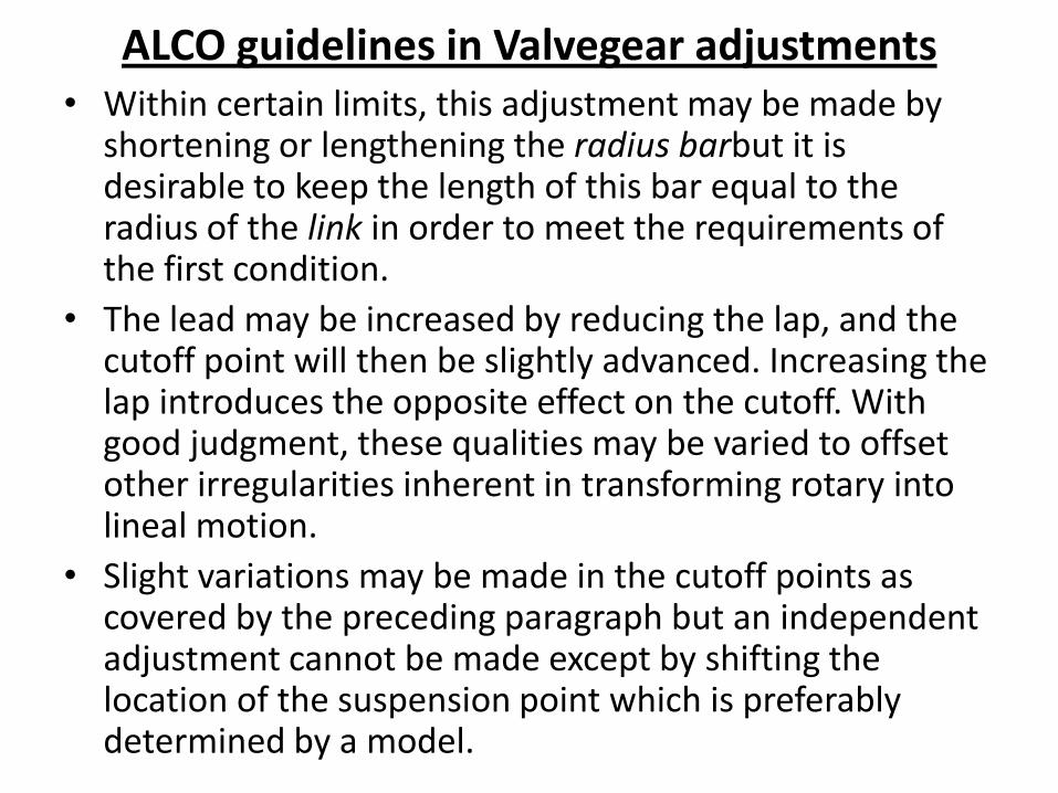
ALCO guidelines in Valvegear adjustments • Within certain limits, this adjustment may be made by
shortening or lengthening the radius barbut it is desirable to keep the length of this bar equal to the radius of the link in order to meet the requirements of the first condition.
• The lead may be increased by reducing the lap, and the cutoff point will then be slightly advanced. Increasing the lap introduces the opposite effect on the cutoff. With good judgment, these qualities may be varied to offset other irregularities inherent in transforming rotary into lineal motion.
• Slight variations may be made in the cutoff points as covered by the preceding paragraph but an independent adjustment cannot be made except by shifting the location of the suspension point which is preferably determined by a model.
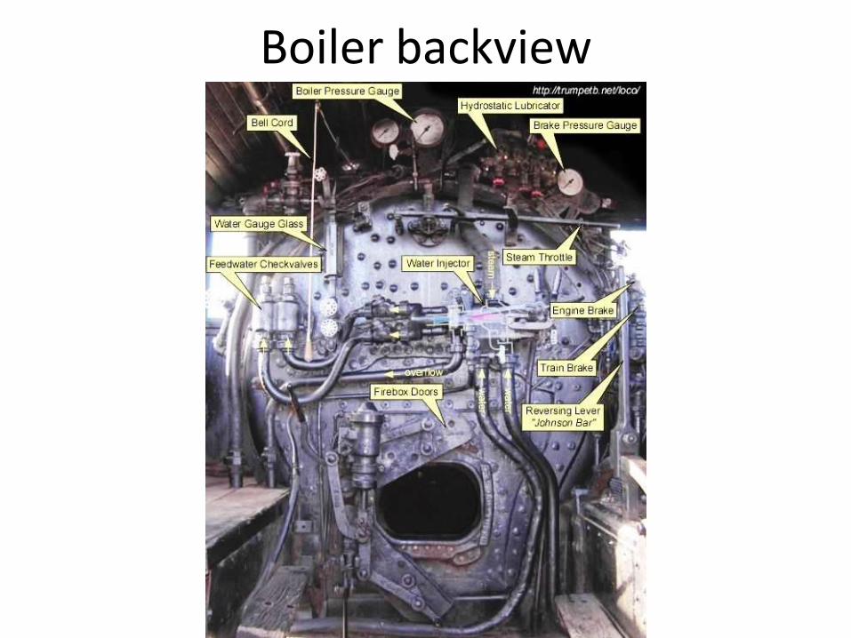
Boiler backview
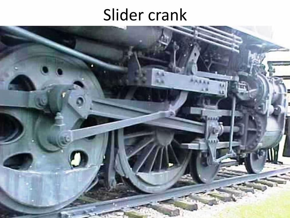
Slider crank
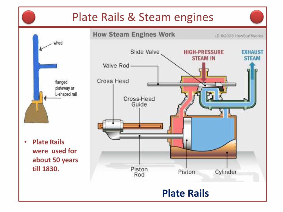
Plate Rails & Steam engines
Plate Rails
• Plate Rails were used for about 50 years till 1830.

Evolution of Rails & Conical Wheels
Edge Rails for Flanged Wheels Steam Boilers

Rails/tracks
Modern Days Rails
• Gauge is the Internal Distance between the 2 Rails

Wide Gauge Rails
Railway Gauges
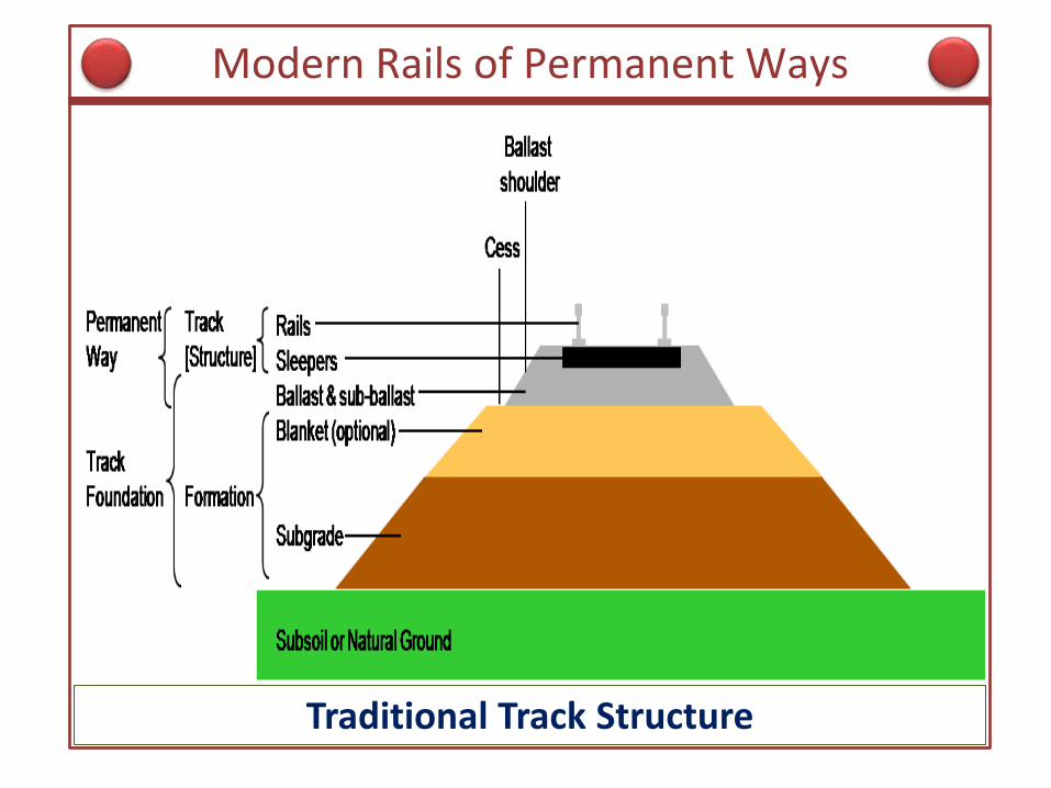
Modern Rails of Permanent Ways
Traditional Track Structure

Garratt : New South Wales - 1970
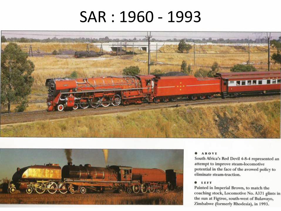
SAR : 1960 - 1993

Air Cooled MG Steam Condensing 1953 Locomotive : SAR - Details

SAR steep gradient steam locomotive {900 tons} : Landau colliery – Transvaal
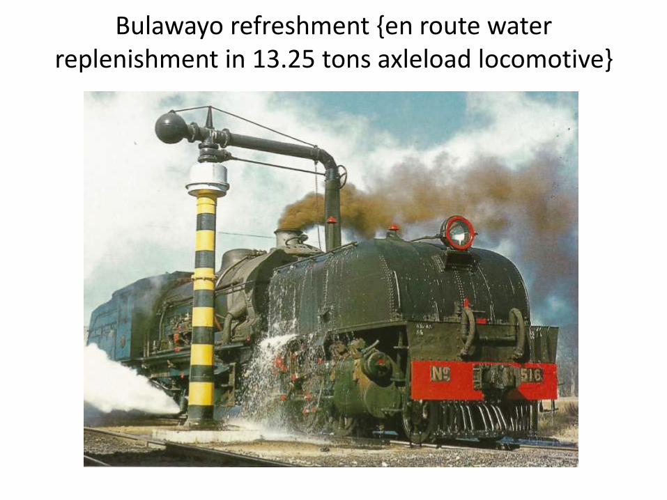
Bulawayo refreshment {en route water replenishment in 13.25 tons axleload locomotive}
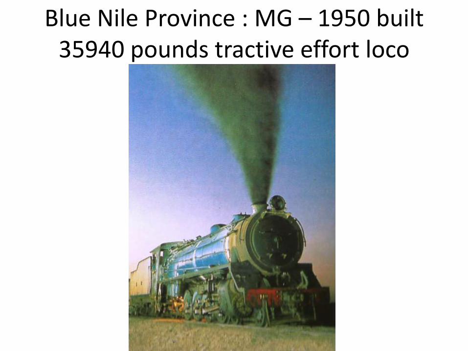
Blue Nile Province : MG – 1950 built 35940 pounds tractive effort loco

Cuban Oil fired loco

Pakistan BG Railways Oil fired steam locomotive

PR {BG} Coal fired Steam locomotive
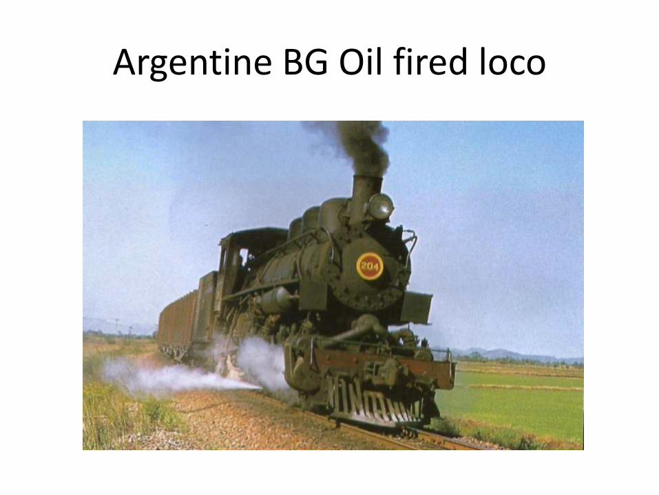
Argentine BG Oil fired loco

Czechoslovakian UIC coal fired loco

Trans Siberian Railways UIC 5 ft standard gauge locomotive
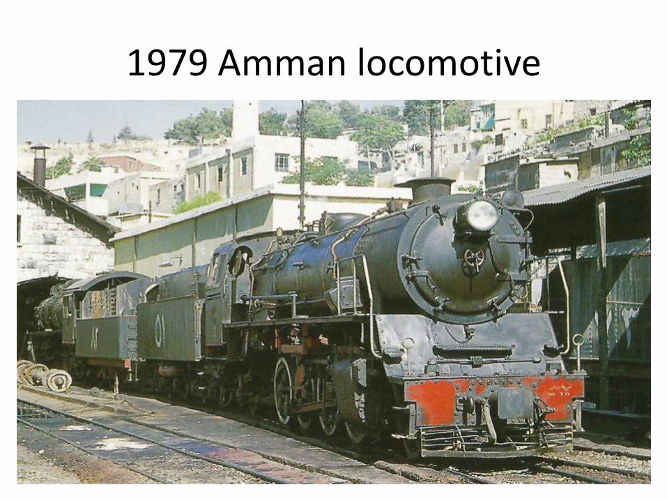
1979 Amman locomotive

1959 CLW IR BG Steam locomotive

Rajamundry overhead water filling
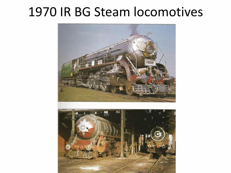
1970 IR BG Steam locomotives

Chinese Manufacturing

Datong Locomotive Works {Shanxi}

Tangshan Locomotive Works {Hebei}
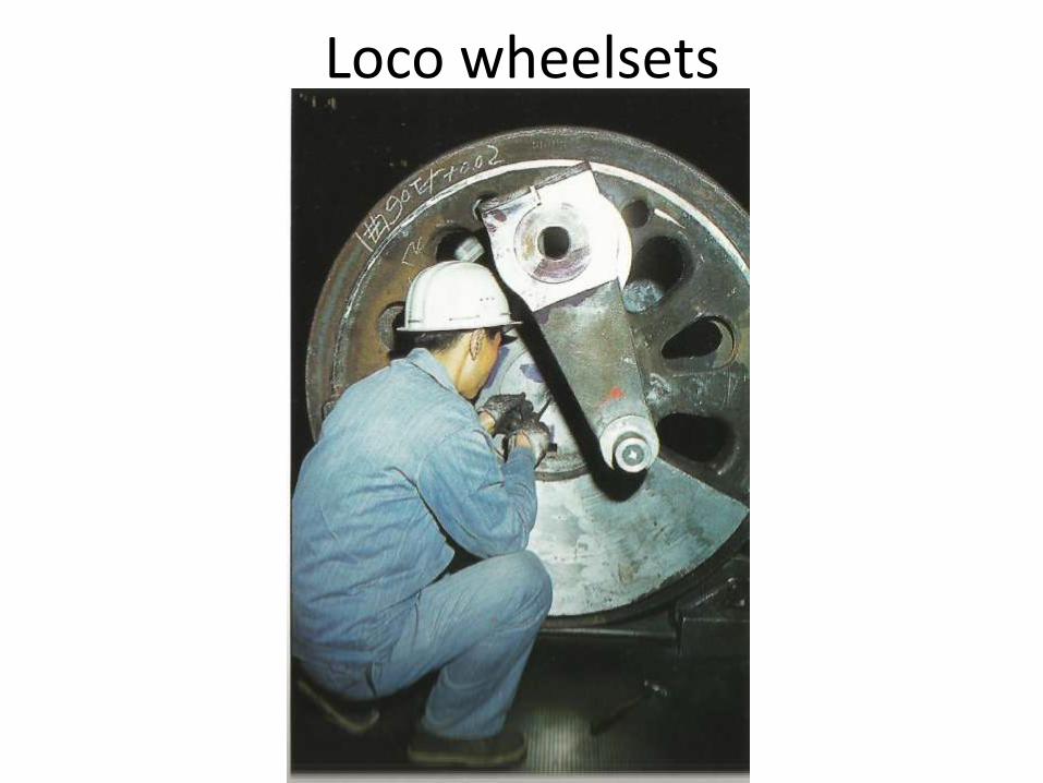
Loco wheelsets
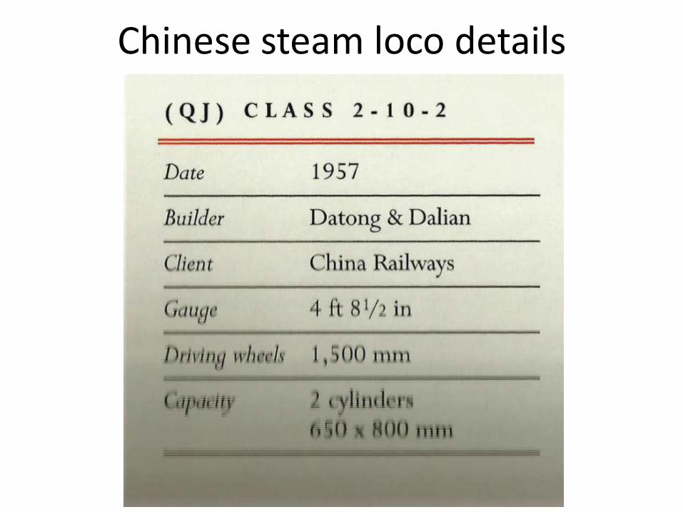
Chinese steam loco details
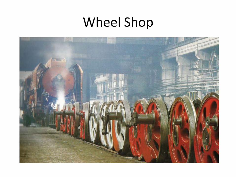
Wheel Shop

SY Class Industrial 2 8 2 loco facts
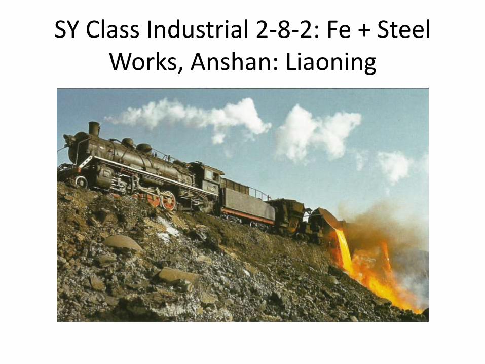
SY Class Industrial 2-8-2: Fe + Steel Works, Anshan: Liaoning

Thank You


