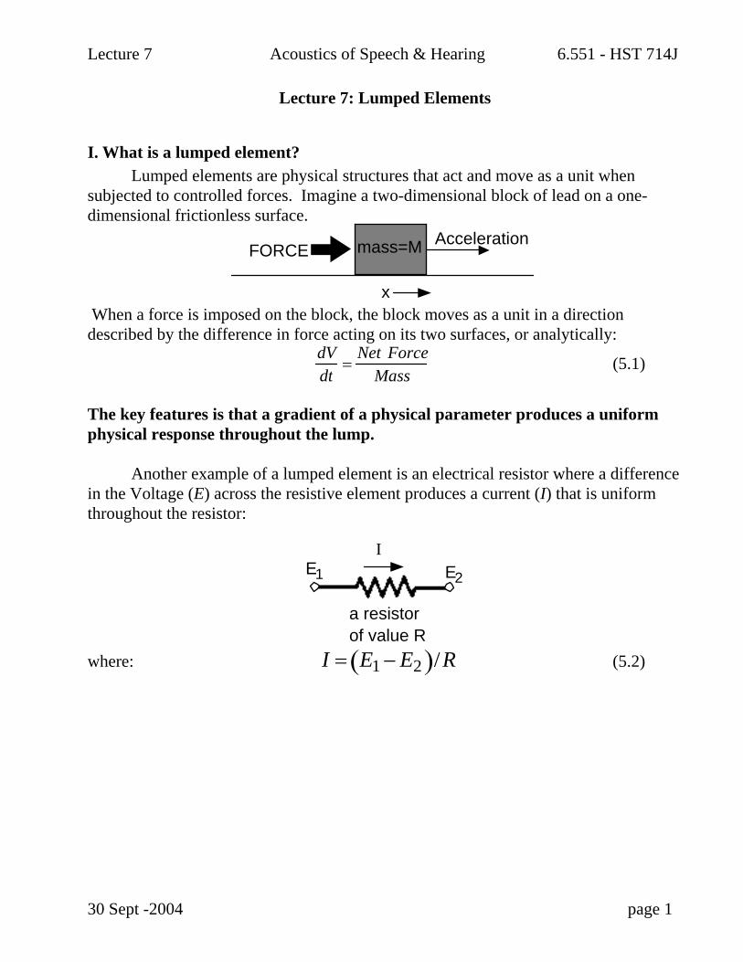
Lecture 7 Acoustics of Speech & Hearing 6.551 - HST 714J Lecture 7: Lumped Elements I. What is a lumped element? Lumped elements are physical structures that act and move as a unit when subjected to controlled forces. Imagine a two-dimensional block of lead on a one- dimensional frictionless surface. x mass=M FORCE Acceleration When a force is imposed on the block, the block moves as a unit in a direction described by the difference in force acting on its two surfaces, or analytically: dV dt = Net Force Mass (5.1) The key features is that a gradient of a physical parameter produces a uniform physical response throughout the lump. Another example of a lumped element is an electrical resistor where a difference in the Voltage (E) across the resistive element produces a current (I) that is uniform throughout the resistor: I E 1 E 2 a resistor of value R where: I = E 1 − E 2 ( ) / R (5.2) 30 Sept -2004 page 1
I. What is a lumped element? Lumped elements are physical structures that act and move as a unit when subjected to controlled forces. Imagine a two-dimensional block of lead on a one-dimensional frictionless surface.
x
mass=MFORCEAcceleration
When a force is imposed on the block, the block moves as a unit in a direction described by the difference in force acting on its two surfaces, or analytically:
dVdt
=Net Force
Mass (5.1)
The key features is that a gradient of a physical parameter produces a uniform physical response throughout the lump. Another example of a lumped element is an electrical resistor where a difference in the Voltage (E) across the resistive element produces a current (I) that is uniform throughout the resistor:
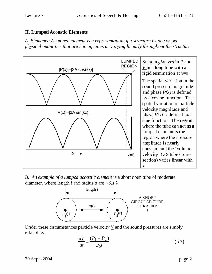
A. Elements: A lumped element is a representation of a structure by one or two physical quantities that are homogenous or varying linearly throughout the structure
Standing Waves in P and V in a long tube with a rigid termination at x=0. The spatial variation in the sound pressure magnitude and phase P(x) is defined by a cosine function. The spatial variation in particle velocity magnitude and phase V(x) is defined by a sine function. The region where the tube can act as a lumped element is the region where the pressure amplitude is nearly constant and the ‘volume velocity’ (v x tube cross-section) varies linear with x.
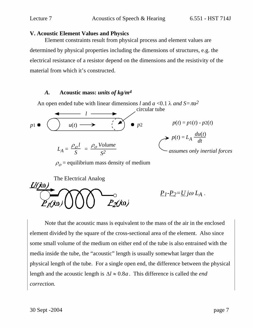
B. An example of a lumped acoustic element is a short open tube of moderate diameter, where length l and radius a are <0.1 λ.
u(t)
p1(t) p
2(t)
length l
A SHORT CIRCULAR TUBE
OF RADIUS a
Under these circumstances particle velocity V and the sound pressures are simply related by:
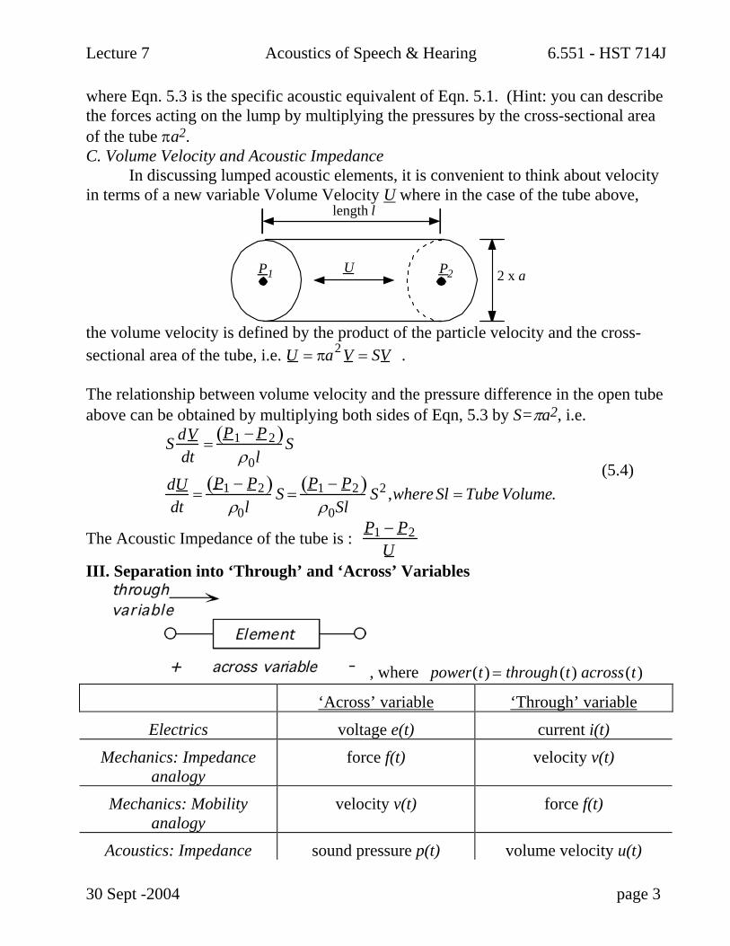
where Eqn. 5.3 is the specific acoustic equivalent of Eqn. 5.1. (Hint: you can describe the forces acting on the lump by multiplying the pressures by the cross-sectional area of the tube πa2. C. Volume Velocity and Acoustic Impedance In discussing lumped acoustic elements, it is convenient to think about velocity in terms of a new variable Volume Velocity U where in the case of the tube above,
UP1
length l
P2 2 x a
the volume velocity is defined by the product of the particle velocity and the cross-sectional area of the tube, i.e. U = πa2 V = SV . The relationship between volume velocity and the pressure difference in the open tube above can be obtained by multiplying both sides of Eqn, 5.3 by S=πa2, i.e.
S dV
dt=
P1 − P2( )ρ0l
S
dUdt
=P1 − P2( )
ρ0lS =
P1 − P2( )ρ0Sl
S2 ,where Sl = Tube Volume. (5.4)
The Acoustic Impedance of the tube is : P1 − P2U
III. Separation into ‘Through’ and ‘Across’ Variables
In all of the above analogies, power(t) = through (t) across(t) has units of watts.
IV. Two Terminal Elements
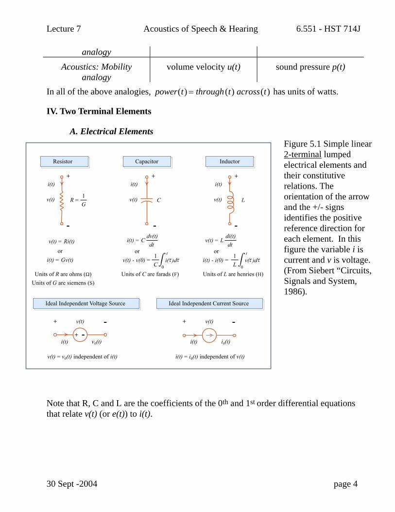
A. Electrical Elements Figure 5.1 Simple linear 2-terminal lumped electrical elements and their constitutive relations. The orientation of the arrow and the +/- signs identifies the positive reference direction for each element. In this figure the variable i is current and v is voltage. (From Siebert “Circuits, Signals and System, 1986).
Note that R, C and L are the coefficients of the 0th and 1st order differential equations that relate v(t) (or e(t)) to i(t).
30 Sept -2004 page 4
Units of R are ohms (Ω)Units of G are siemens (S)
v(t) = v0(t) independent of i(t) i(t) = i0(t) independent of v(t)
Units of C are farads (F) Units of L are henries (H)
LC v(t)v(t)
v(t)
i(t)i(t)
v0(t)i(t)
v(t)
i0(t)i(t)
+
-
+
+
- + --
+
-
v(t)
v(t) = Ri(t)
i(t)+
-i(t) = C
dv(t)dt
v(t) = Ldi(t)dt
R =1G
t t
0
1C
orv(t) - v(0) = i( )d
0
1L
ori(t) - i(0) = v( )d
ori(t) = Gv(t)
Resistor Capacitor Inductor
Ideal Independent Voltage Source Ideal Independent Current Source
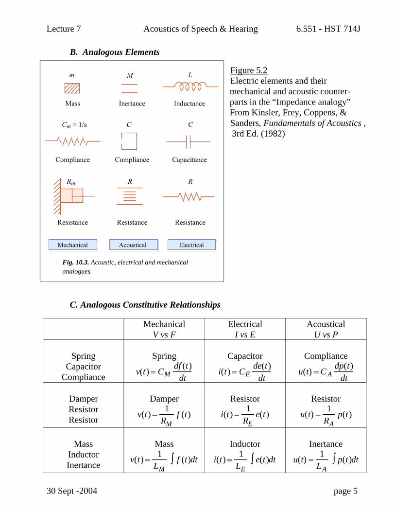
Figure 5.2 Electric elements and their mechanical and acoustic counter- parts in the “Impedance analogy” From Kinsler, Frey, Coppens, & Sanders, Fundamentals of Acoustics , 3rd Ed. (1982)
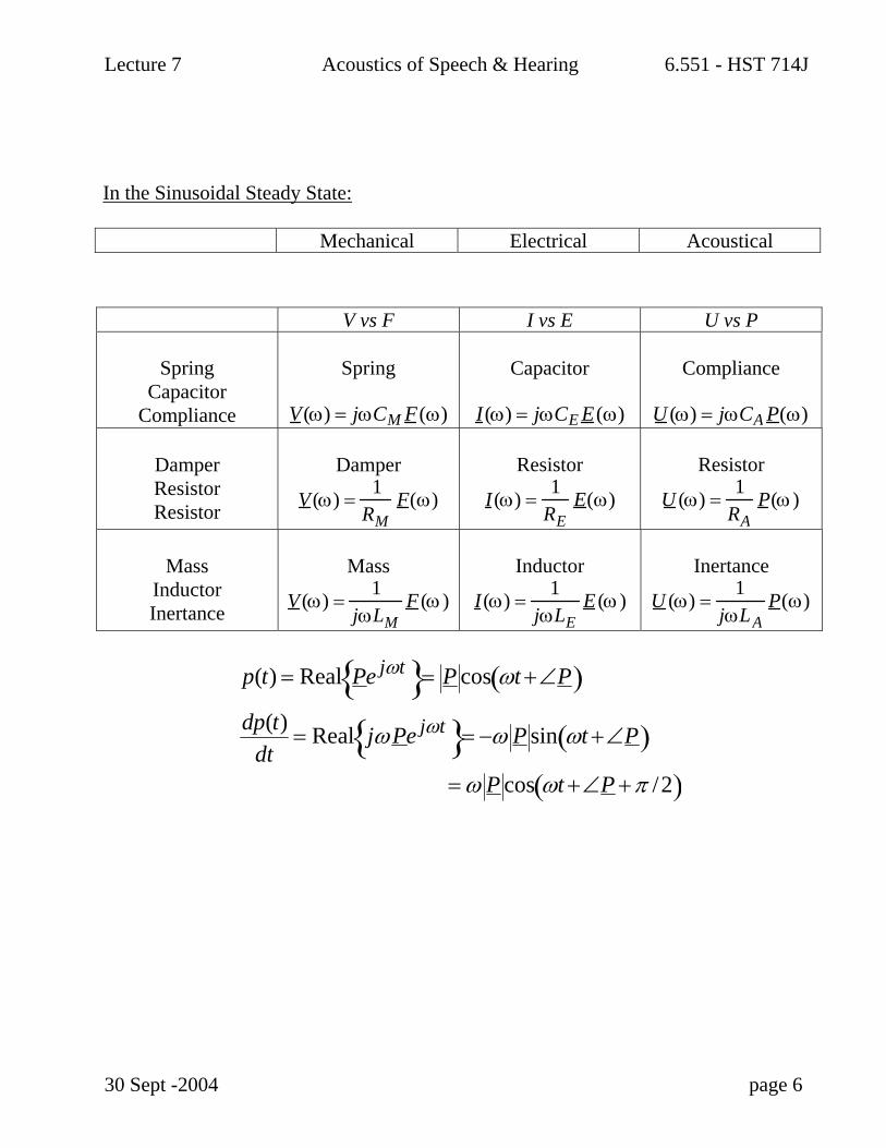
C. Analogous Constitutive Relationships
Mechanical V vs F
Electrical I vs E
Acoustical U vs P
Spring
Capacitor Compliance
Spring
v(t) = CMdf (t)
dt
Capacitor
i(t) = CEde(t)
dt
Compliance
u(t) = C Adp(t)
dt
Damper Resistor Resistor
Damper
v(t) =1
RMf (t)
Resistor
i(t) =1
REe(t)
Resistor
u(t) =1
RAp(t)
Mass
Inductor Inertance
Mass
v(t) =1
LMf (t)∫ dt
Inductor
i(t) =1
LEe(t)∫ dt
Inertance
u(t) =1
LAp(t)∫ dt
30 Sept -2004 page 5
Mass
m
Cm = 1/s
Rm R R
C C
M L
Inertance Inductance
Compliance Compliance
Resistance
Fig. 10.3. Acoustic, electrical and mechanicalanalogues.
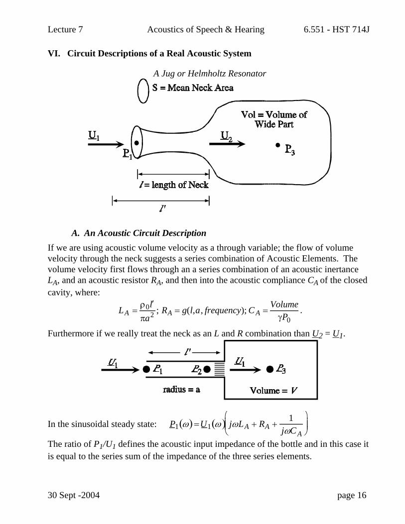
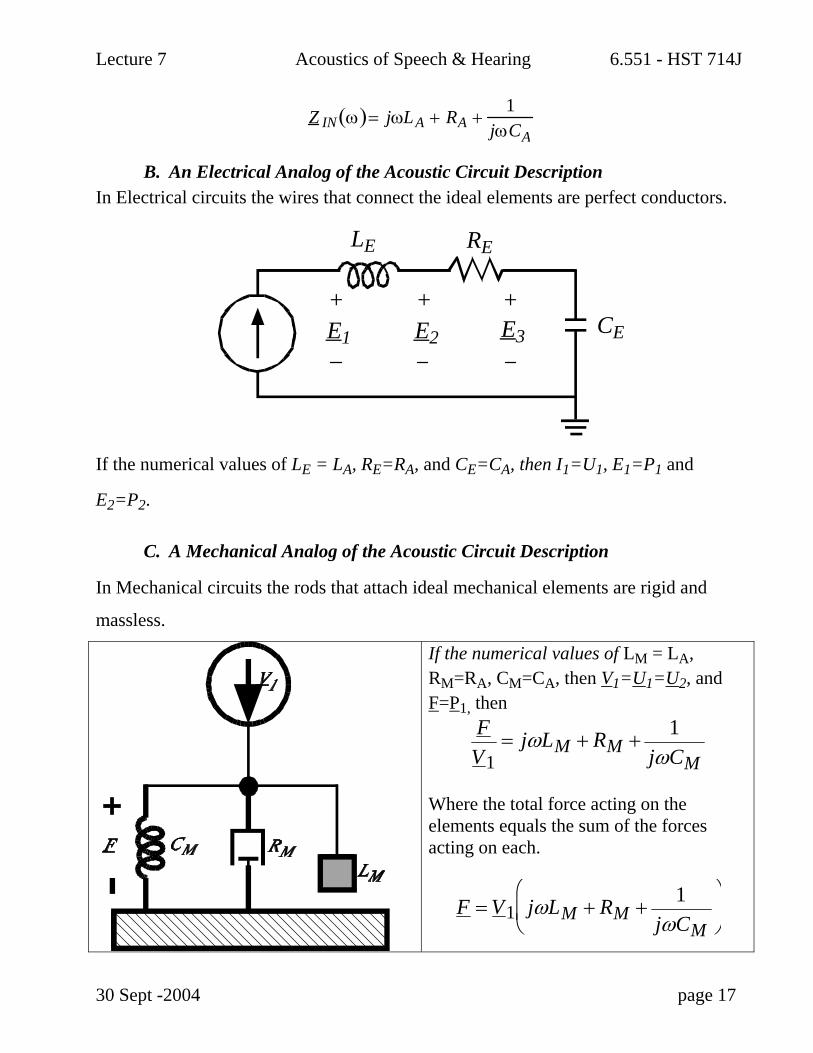
VI. Circuit Descriptions of a Real Acoustic System
A Jug or Helmholtz Resonator
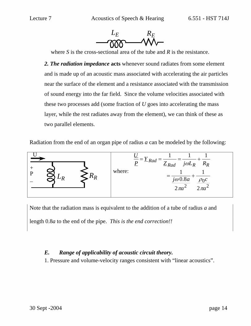
A. An Acoustic Circuit Description If we are using acoustic volume velocity as a through variable; the flow of volume velocity through the neck suggests a series combination of Acoustic Elements. The volume velocity first flows through an a series combination of an acoustic inertance LA, and an acoustic resistor RA, and then into the acoustic compliance CA of the closed cavity, where:
LA =ρ0 ′ l πa2 ; RA = g(l,a, frequency); C A =
VolumeγP0
.
Furthermore if we really treat the neck as an L and R combination than U2 = U1.
In the sinusoidal steady state: P1 ω( ) =U1 ω( ) jωLA + RA +1
jωC A
⎛
⎝ ⎜ ⎜
⎞
⎠ ⎟ ⎟
The ratio of P1/U1 defines the acoustic input impedance of the bottle and in this case it is equal to the series sum of the impedance of the three series elements.


![A Boundary Element Model for Underwater Acoustics in ... · equation [Kinsler, Frey, Coppens and Sanders (1982)]:](https://static.documents.pub/doc/80x56/5b84191f7f8b9ad34a8b85a9/a-boundary-element-model-for-underwater-acoustics-in-equation-kinsler.jpg)


