42
ARCES -Advanced Research Centre on Electronic Systems University of Bologna - Italy Thursday, 2 nd November 2006 Lumped-element modelling of RF-MEMS Roberto Gaddi Email: [email protected]
| Date post: | 20-Feb-2019 |
| Category: |
Documents |
| Upload: | truongcong |
| View: | 228 times |
| Download: | 0 times |

ARCES -Advanced Research Centre on Electronic Systems
University of Bologna - Italy
Thursday, 2nd November 2006
Lumped-element modellingof RF-MEMS
Roberto Gaddi
Email: [email protected]

ARCES - University of Bologna
Strutture MEMS in un transceiver a radio frequenza
Potenziale applicativo dei MEMS include la sostituzionedi componenti tradizionali
ARCES - University of Bologna
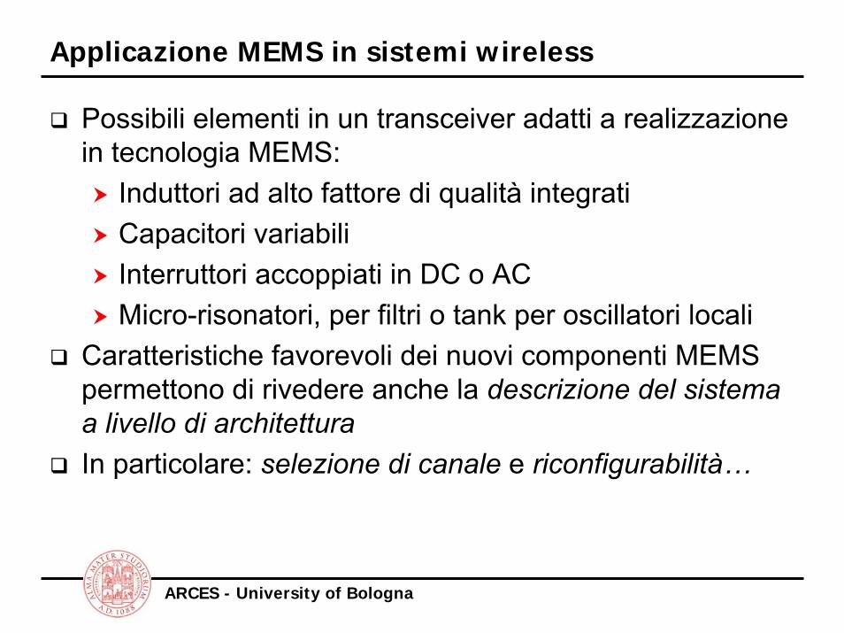
Applicazione MEMS in sistemi wireless
Possibili elementi in un transceiver adatti a realizzazionein tecnologia MEMS:
Induttori ad alto fattore di qualità integratiCapacitori variabiliInterruttori accoppiati in DC o ACMicro-risonatori, per filtri o tank per oscillatori locali
Caratteristiche favorevoli dei nuovi componenti MEMS permettono di rivedere anche la descrizione del sistema a livello di architetturaIn particolare: selezione di canale e riconfigurabilità…

ARCES - University of Bologna
Componenti passivi ad alto fattore di qualità
Induttori integrati isolati dal substrato semiconduttivohanno perdite ridotte ⇒ maggiore fattore di idealità (Q)

ARCES - University of Bologna
Interruttori MEMS accoppiati in DC o AC-RF
Deformazioni di strutture conduttive, tramite trasduzione elettrostatica o magnetica, si utilizza per implementareinterruttori

ARCES - University of Bologna
Capacitori variabili integrati
Tramite strutture deformabili e trasduzione elettrostaticaè possibile realizzare capacitori variabili MEMS integrati

ARCES - University of Bologna
Esempio: ricevitore a banco di switch

ARCES - University of Bologna
Simulation approaches for MEMS
System Level
Sub-system / Circuit Level
Device / Physical LevelTOP-DOWN
BOTTOM-UP
• System modeling• Behavioral analysis of complete MEMS devices
• Reduced order modeling• Electrical equivalent• Lumped elements• Modified nodal analysis
• 3D modeling• FEM / FVM / BEM field solvers• Coupled domains

ARCES - University of Bologna
Sub-system / Circuit Level Modeling
This modeling level involves:Terminal characteristics description of a sub-systemMultiple physical domains phenomena and quantitiesHierarchy compatible model complexity
Reduced-order modelling approach:Starts from exact continuous 3D modelling; space discretisation and reduction of mechanical degrees of freedom are appliedUsually requires expertise and intuition to avoid loss of significant device behaviour descriptionLately some automated model reduction tools are available also from commercial CAD toolsSeems more appropriate to a bottom-up design methodology…

ARCES - University of Bologna
Generalized Kirkhoffian networks
Kirkhoffian network theory is applicable to diverse energy domains, provided that:
Flow (through) and difference (across) quantities can be identified, with relationships between them given as implicit/explicit equations or differential equations depending only on terminal quantities and internal states. Conservation laws apply:Zero sum of across quantity along a closed network loopZero sum of through quantity into a node or network cut-set
Physical domain Flow quantity Difference quantityElectrical Current Voltage
Mechanical-trans Force Velocity / Displ.
Mechanical-rot Torque Ang. Velocity / Displ.
Pneumatic Volume Flow PressureThermal Heat Flow Temperature
ARCES - University of Bologna
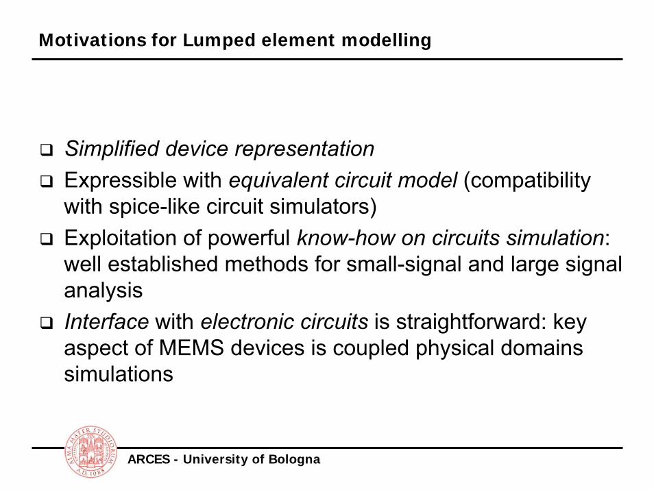
Motivations for Lumped element modelling
Simplified device representationExpressible with equivalent circuit model (compatibility with spice-like circuit simulators)Exploitation of powerful know-how on circuits simulation: well established methods for small-signal and large signal analysisInterface with electronic circuits is straightforward: key aspect of MEMS devices is coupled physical domains simulations

ARCES - University of Bologna
Power flow
Two components can exchange energy:
A BPAB
PBA
Power flow is energy flow per unit time:
PAB=r12 PBA=r2
2
Net Power Flow from A to B is:PNet=r1
2-r22=(r1+r2)(r1-r2)=e(t)·f(t)
i.e. a product of two real numbers…
ARCES - University of Bologna
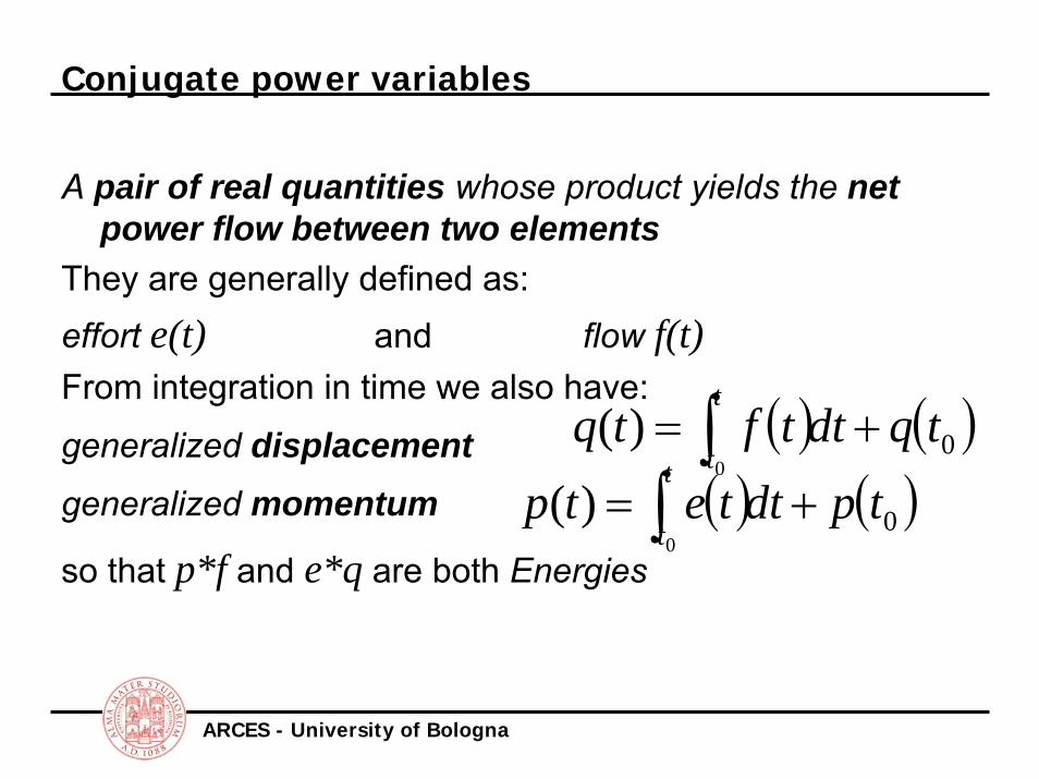
Conjugate power variables
A pair of real quantities whose product yields the net power flow between two elements
They are generally defined as:effort e(t) and flow f(t)From integration in time we also have:
generalized displacementgeneralized momentum
so that p*f and e*q are both Energies
( ) ( )00
)( tqdttftqt
t+= ∫
( ) ( )00
)( tpdttetpt
t+= ∫

ARCES - University of Bologna
Example: mechanical power variables
Effort will be a Force, Flow will be Velocity:Power = Force * VelocityEnergy = Force * Displacement
= Momentum * VelocityNote: in n-dimensional space we have scalar products
of vectors…
viscFr
vr

ARCES - University of Bologna
Conjugate power variables
ARCES - University of Bologna
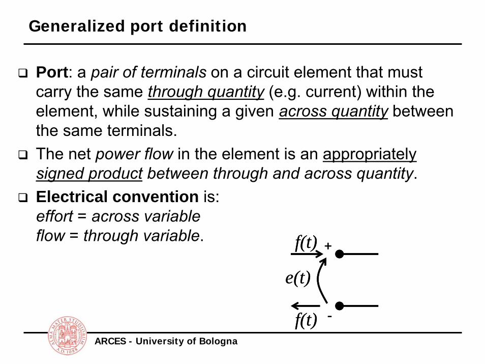
Generalized port definition
Port: a pair of terminals on a circuit element that must carry the same through quantity (e.g. current) within the element, while sustaining a given across quantity between the same terminals.The net power flow in the element is an appropriately signed product between through and across quantity.Electrical convention is:effort = across variableflow = through variable.
+
-
e(t)
f(t)
f(t)
+
-
e(t)
f(t)
f(t)
ARCES - University of Bologna
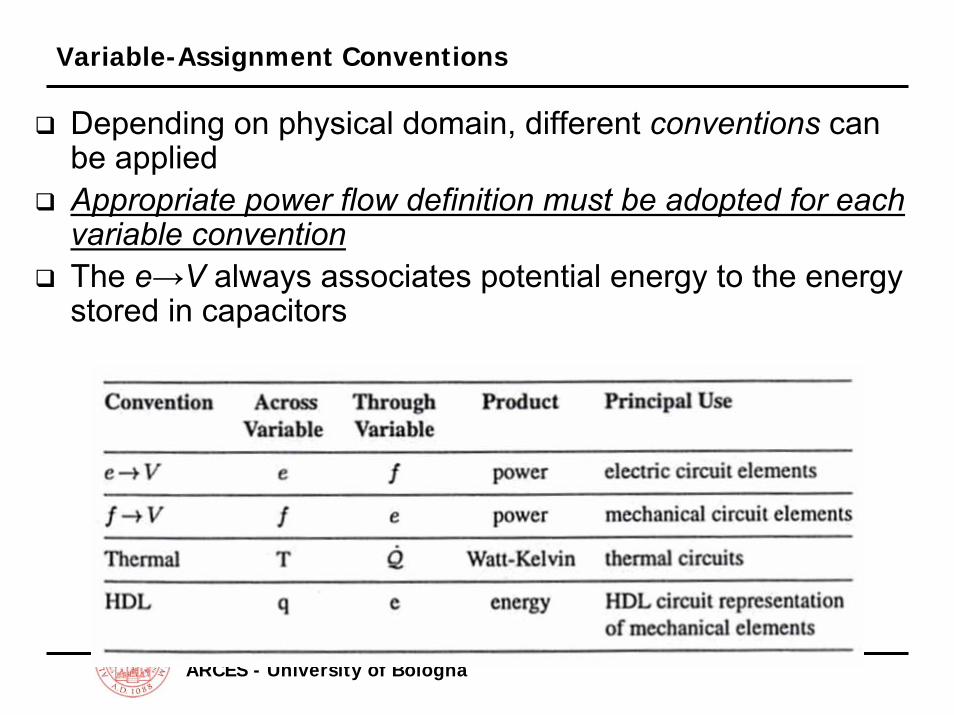
Variable-Assignment Conventions
Depending on physical domain, different conventions can be appliedAppropriate power flow definition must be adopted for each variable conventionThe e→V always associates potential energy to the energy stored in capacitors
ARCES - University of Bologna
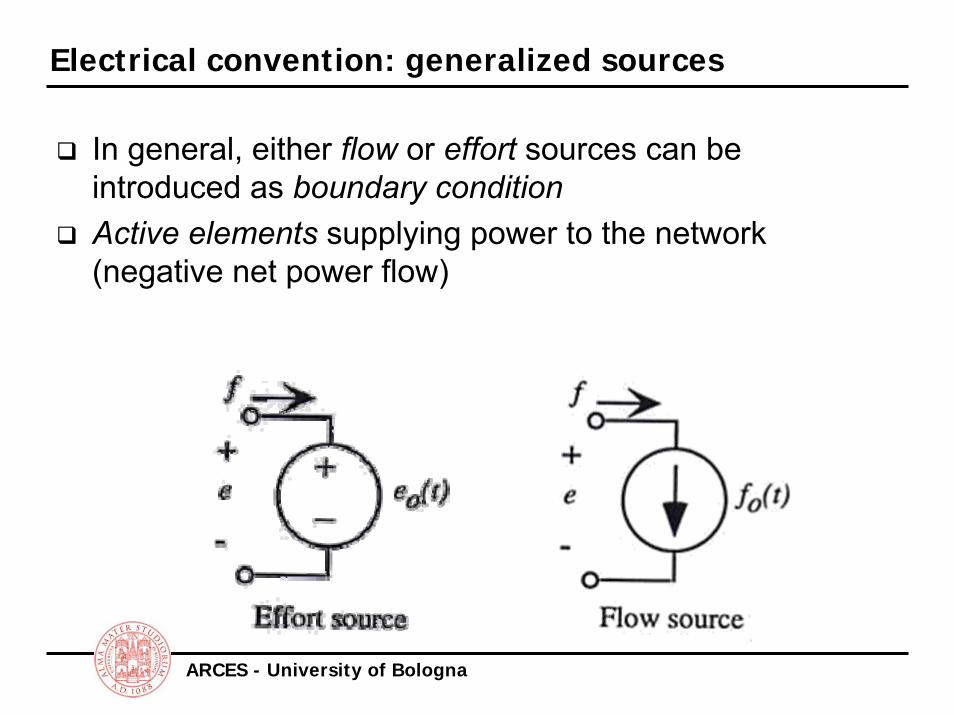
Electrical convention: generalized sources
In general, either flow or effort sources can be introduced as boundary conditionActive elements supplying power to the network (negative net power flow)
ARCES - University of Bologna
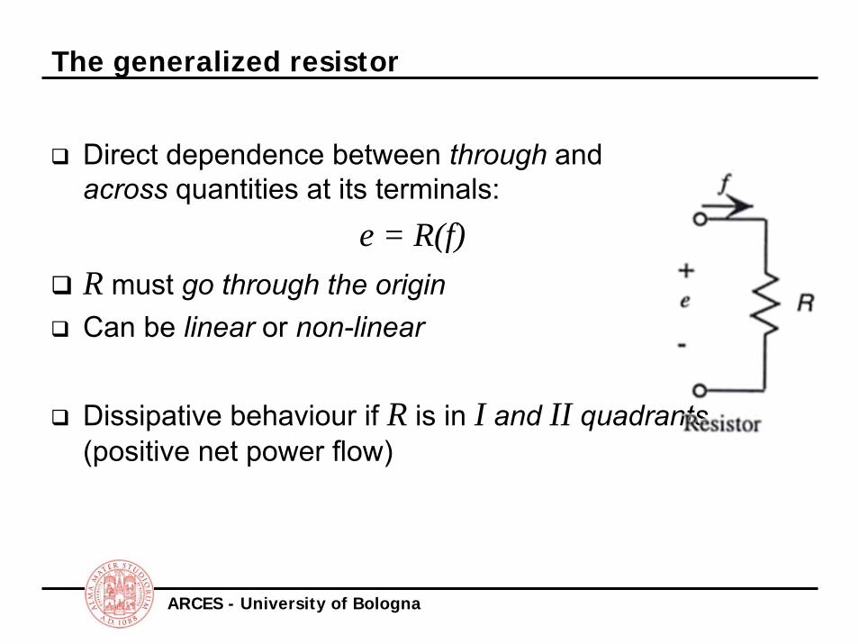
The generalized resistor
Direct dependence between through and across quantities at its terminals:
e = R(f)R must go through the originCan be linear or non-linear
Dissipative behaviour if R is in I and II quadrants(positive net power flow)

ARCES - University of Bologna
The generalized capacitor
Direct relation between effortand displacement:
e = Φ(q)Φ is a well behaved functiongoing through the originElement associated to potential energy storage:
( ) ∫ ⋅=1
01
q
dqeqW
( ) ∫ ⋅=1
01
*e
deqeW

ARCES - University of Bologna
The electrical capacitor
A parallel plate capacitor, ideal, is defined by the following:
The energy stored in the capacitor is:CQV =
CQdqqVQW
Q
2)()(
2
0
== ∫

ARCES - University of Bologna
The Hooke’s Law spring
The force (flow) F is related to the displacement x by a linear function:
F=kxThe stored energy in the spring as displaced by x1 is:
Same potential energy as electrical capacitance: the two elements are equivalent (e→V convention)
21
01 2
1)()(1
kxdxxFxWx
== ∫k
C 1↔

ARCES - University of Bologna
The generalized inertance
Electrical inductance, generalizedas the function relation between the flow f and the momentum p
f=Ψ(p)Ψ must go through the origin of the f-p planeIt is related to stored kinetic energy:
( ) ∫ ⋅=1
01
p
dpfpW

ARCES - University of Bologna
The electrical inductance
Inductance definition:
If we were to define an electrical momentum it would be:
So we recognize the inertance definition:
The stored kinetic energy and co-energy are:
0
0
)( idtLvti
dtdiLv
t
t∫ +=→⋅=
0
0
)( e
t
te pvdttp ∫ +=
( )0)(1)( ee ptpL
ti −=
211
*21
1 21)(
2)( LiiW
LppW ==
ARCES - University of Bologna
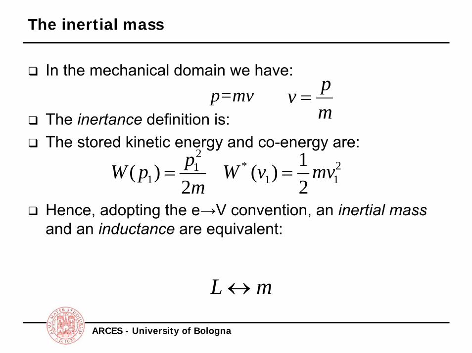
The inertial mass
In the mechanical domain we have:p=mv
The inertance definition is:The stored kinetic energy and co-energy are:
Hence, adopting the e→V convention, an inertial massand an inductance are equivalent:
mpv =
211
*21
1 21)(
2)( mvvW
mppW ==
mL ↔
ARCES - University of Bologna
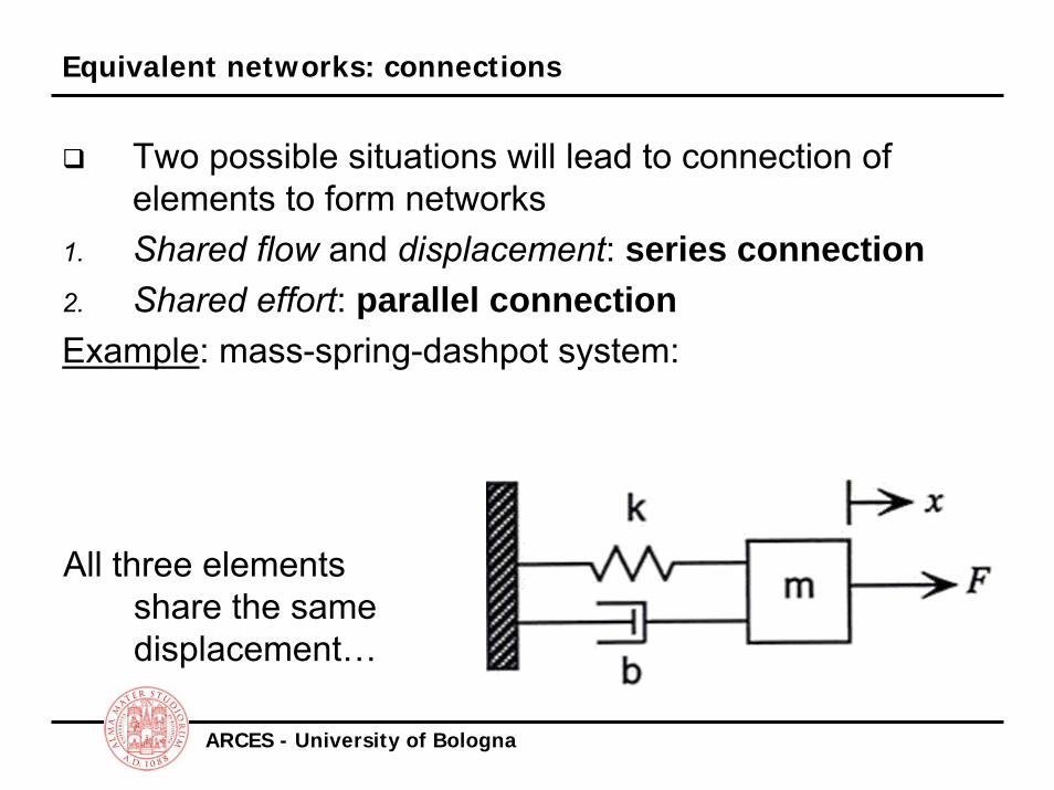
Equivalent networks: connections
Two possible situations will lead to connection of elements to form networks
1. Shared flow and displacement: series connection2. Shared effort: parallel connectionExample: mass-spring-dashpot system:
All three elementsshare the samedisplacement…
ARCES - University of Bologna
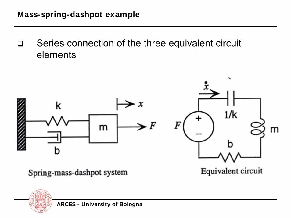
Mass-spring-dashpot example
Series connection of the three equivalent circuit elements

ARCES - University of Bologna
Kirchhoff’s Laws
Connectivity between circuit elements is based on generalized Kirchhoff’s lawsTheir validity is maintained across diverse physical domains
Kirchhoff’s Current Law (KCL): The sum of all currents (flows) entering a node is zero
Kirchhoff’s Voltage Law (KVL): The oriented sum of all voltages (efforts) around any closed path is zero
ARCES - University of Bologna
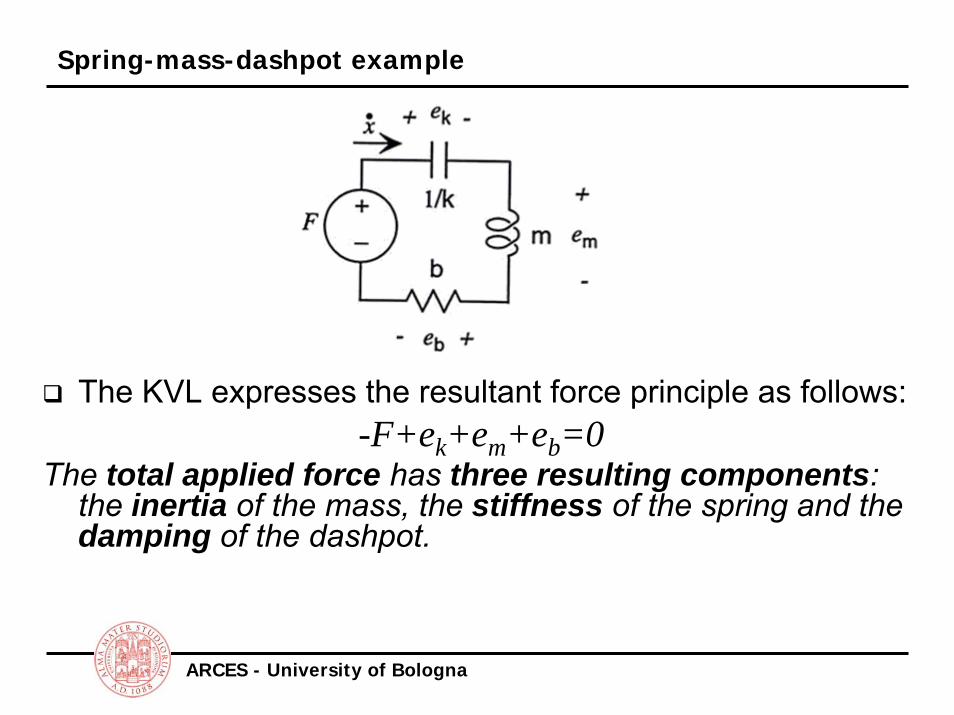
Spring-mass-dashpot example
The KVL expresses the resultant force principle as follows:-F+ek+em+eb=0
The total applied force has three resulting components: the inertia of the mass, the stiffness of the spring and the damping of the dashpot.
ARCES - University of Bologna
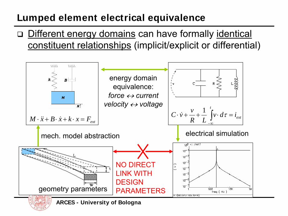
Lumped element electrical equivalence
Different energy domains can have formally identical constituent relationships (implicit/explicit or differential)
extFxkxBxM =⋅+⋅+⋅ &&& ext
t
idvLR
vvC =⋅++⋅ ∫∞−
τ1&
geometry parameters
mech. model abstraction
energy domain equivalence:
force ↔ currentvelocity ↔ voltage
electrical simulation
NO DIRECT LINK WITH DESIGN PARAMETERS
ARCES - University of Bologna
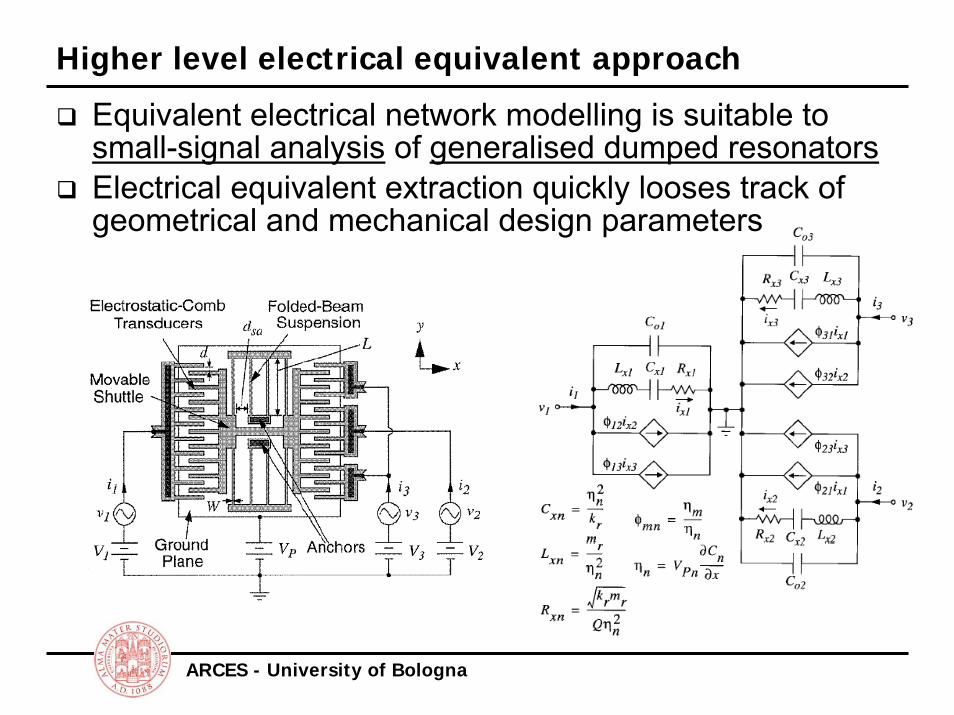
Higher level electrical equivalent approach
Equivalent electrical network modelling is suitable to small-signal analysis of generalised dumped resonatorsElectrical equivalent extraction quickly looses track of geometrical and mechanical design parameters
ARCES - University of Bologna
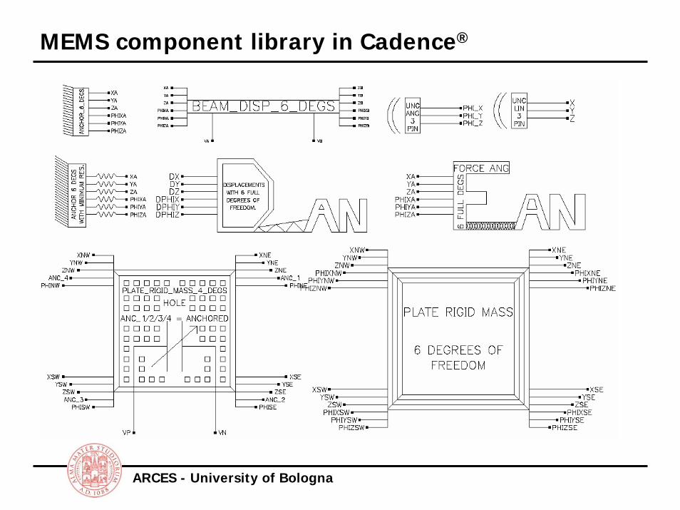
MEMS component library in Cadence®
ARCES - University of Bologna
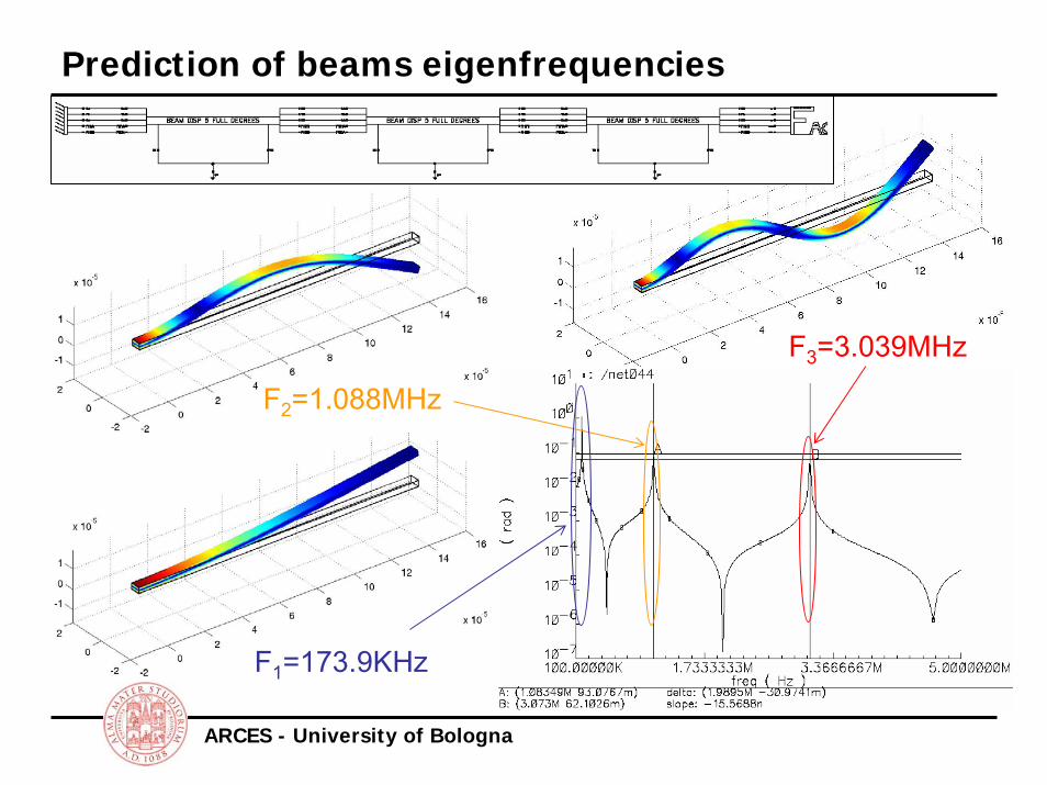
Prediction of beams eigenfrequencies
F1=173.9KHz
F2=1.088MHz
F3=3.039MHz

ARCES - University of Bologna
Resonance modes of a composite device (1)
res1=110kHz res2=225kHzres3=275kHz res4=350kHz
ARCES - University of Bologna
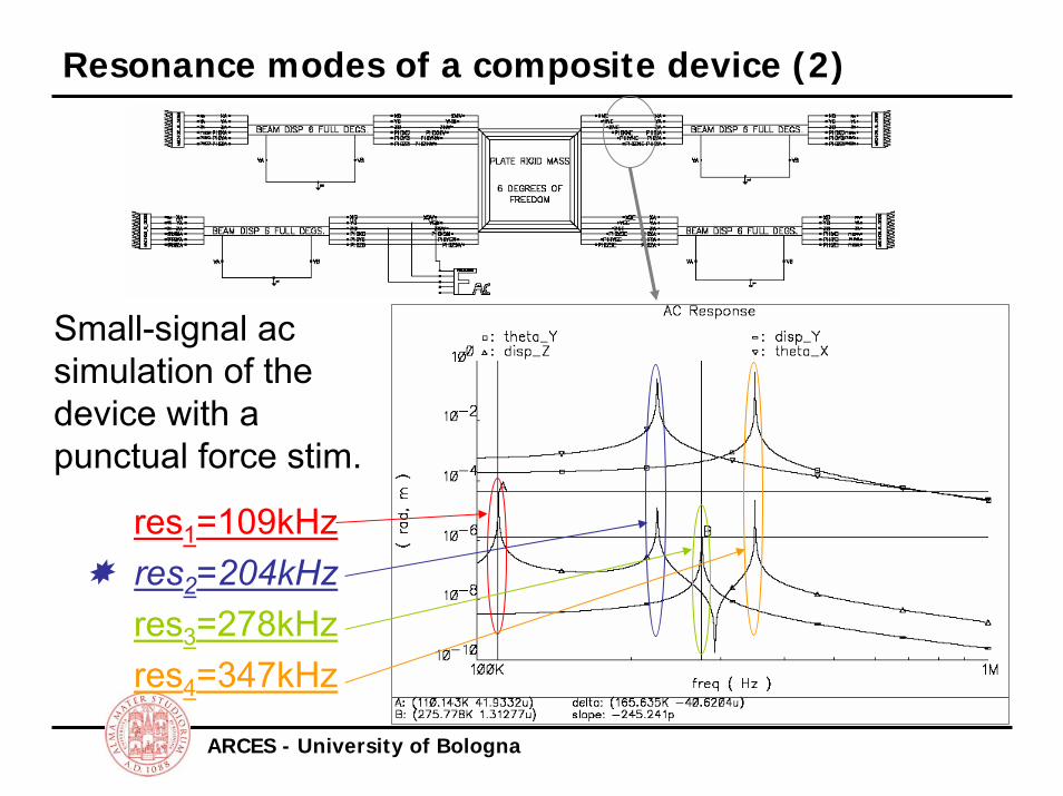
Resonance modes of a composite device (2)
Small-signal ac simulation of the device with a punctual force stim.
res1=109kHzres2=204kHzres3=278kHzres4=347kHz
ARCES - University of Bologna
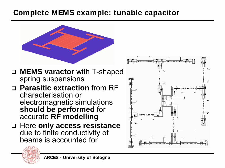
Complete MEMS example: tunable capacitor
MEMS varactor with T-shaped spring suspensionsParasitic extraction from RF characterisation or electromagnetic simulations should be performed for accurate RF modellingHere only access resistancedue to finite conductivity of beams is accounted for

ARCES - University of Bologna
MEMS Varactor top-down design (1)
Critical specs for varactor as tuning element within an electronic circuit are: tuning ratio (Cmax/Cmin), nominal capacitance (Cnom) and pull-in voltage (VPI)
Vbias
Z-pos
Vbias
Z-posAll geometrical parameters are available for design: MEMS design tool based on Spectre simulatorParametric static (DC) simulations quickly allow for Pull-in voltage design

ARCES - University of Bologna
MEMS Varactor top-down design (2)
The tuning ratio is technology defined
A sweep from 200x200μm2 to 400x400μm2, at f=1.8GHz and bias voltage VNOM
ox
oxairox
ttg
CC +
=ε
min
max
Total plate area A and nominal voltage VNOM define the capacitance value Cnom
Small signal (ac) analysisperformed at given frequency and sweeping Aleads quickly to the desired nominal capacitance
AA ~=

ARCES - University of Bologna
MEMS Varactor top-down design (3)
Spring beams dimensions control the overall spring constant k, e.g. the pull-in voltageAccess resistance also depends on beams W/LPossible trade-off: tuning range vs. resistive losses
⇓ width: ⇑ tuning range ⇓ Q factor

ARCES - University of Bologna
Varactor transient behaviour
Transient simulationscan give insight to response time to VBIAS
Spectre® simulator does not show any convergence issues, even with added electronicsBoth electrical and mechanical quantities can be observed

ARCES - University of Bologna
Varactor insertion within an LC tank
Typical application can be the tuning element within an LC tank for an RF voltage controlled oscillator (VCO)LC network includes two varactors that provide isolation from controlling voltage

ARCES - University of Bologna
Mixed-domain complete VCO simulation
Differential VCO: CMOS technology from UMC, 0.18μm channel lengthModel library based on BSIM3 modelSpectre achieves convergence in transient analysisPeriodic-steady-state (PSS) simulation for noise analysis still have issues…
time
Vout
time
Vout


