HP SECTION WEEP HOLE
MONITORINGPresented By
Prem BabooSr. Manager(Prod)
National Fertilizers Ltd. India
LEAKAGE DETECTION SYSTEM
MICRO GENIE – SCAN
WEEP HOLE MONITOR
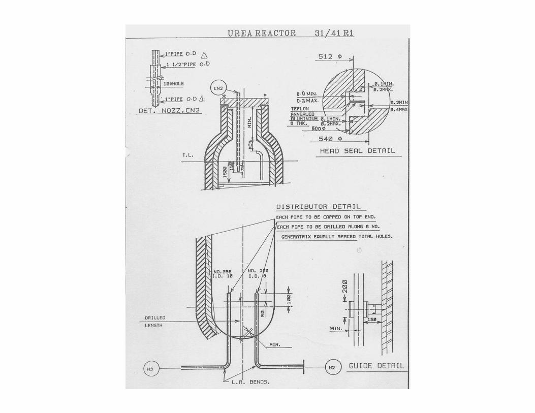
PURPOSE
WEEPHOLE MONITORING SYSTEM FOR REACTOR AND STRIPPER
IN UREA PLANT WAS INSTALLED TO DETECT THE LEAKAGE
FROM VESSELS.
EVERY WEEPHOLE HAS CORRESPONDING WEEPHOLE
CONNECTED TO IT INTERNALLY THROUGH 2 mm DEEP GROOVE.
THE SYSTEM INSTALLED IN SUCH A WAY THAT ONE WEEPHOLE
OUT OF ALL THE CONNECTED PAIRS IS CONNECTED TO
INCOMMING N2 HEADER ON ONE SIDE WHILE THE
CORRESPONDING OPPOSITE WEEPHOLES ARE GROUPED TO
MAKE 4 OR 5 HEADERS.CONNECTED TO THE BUBBLERS FOR
CONTINOUS MONITORING. THIS WILL ENSURE N2 FLOW
THROUGH ALL THE PAIRS OF CONNECTED WEEPHOLES.
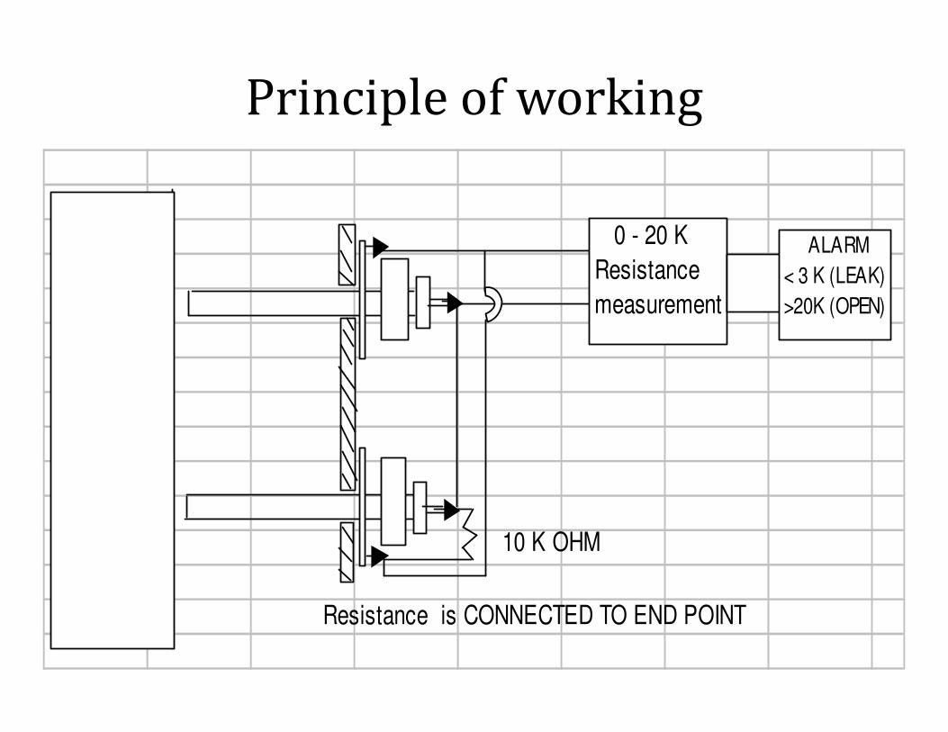
Principle of working
10 K OHM
Resistance is CONNECTED TO END POINT
0 - 20 K
Resistance
measurement
ALARM
< 3 K (LEAK)
>20K (OPEN)
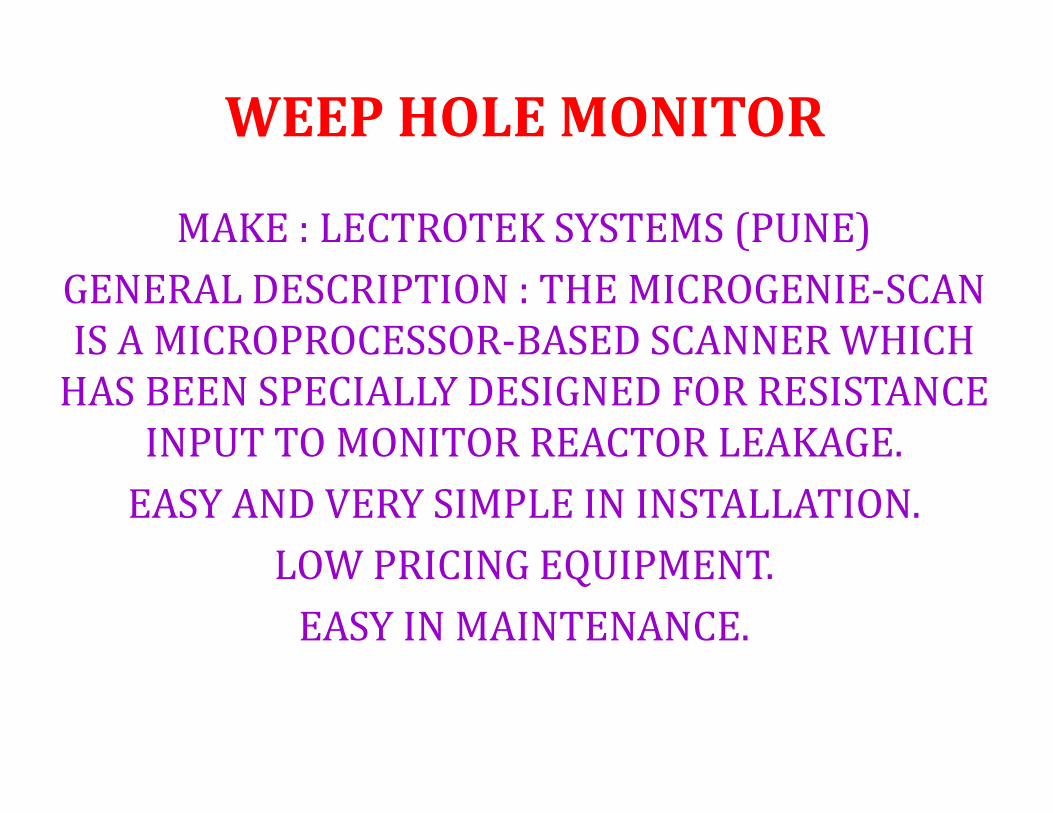
WEEP HOLE MONITOR
MAKE : LECTROTEK SYSTEMS (PUNE)
GENERAL DESCRIPTION : THE MICROGENIE-SCAN
IS A MICROPROCESSOR-BASED SCANNER WHICH
HAS BEEN SPECIALLY DESIGNED FOR RESISTANCE
INPUT TO MONITOR REACTOR LEAKAGE.
EASY AND VERY SIMPLE IN INSTALLATION.
LOW PRICING EQUIPMENT.
EASY IN MAINTENANCE.

OUTSTANDING FEATURES OF
MICROGENIE-SCAN
1.SOFT-TOUCH MEMBRANE KEYS FOR PROGRAMMING.
• 2. PROGRAMMING METHOD IS USER-FRIENDLY.
• 3. NON-VOLATILE MEMORY FOR SETUP DATA ( SET POINTS, PRINT INTERVAL
ETC.).
• 4. DUAL, 4-DIGIT DISPLAYS AND LED BARS FOR INFORMATION.
• 5. PROGRAM INHIBIT FACILITY PROVIDED.
• 6. RS-232-C SERIAL PORT.
• 7. MODULAR CONSTRUCTION OFFERS EASE OF MAINTENANCE.
• 8. EXCLUSIVE FEATURE – SOFTWARE CALIBRATION.
• 9. EXCLUSIVE FEATURE – UNWANTED CHANNELS CAN BE SKIPPED.
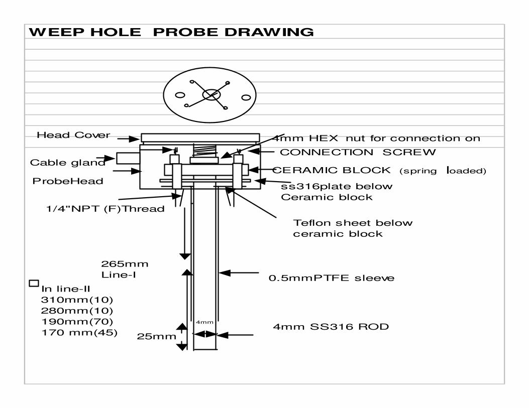
WEEP HOLE PROBE DRAWING
4mm SS316 ROD
0.5mmPTFE sleeve
CERAMIC BLOCK (spring loaded)
CONNECTION SCREW
4mm HEX nut for connection on
Cable gland
ProbeHeadss316plate below
Ceramic block
Teflon sheet below
ceramic block
1/4"NPT (F)Thread
25mm
265mm
Line-I
In line-II
310mm(10)
280mm(10)
190mm(70)
170 mm(45)
4mm
Head Cover
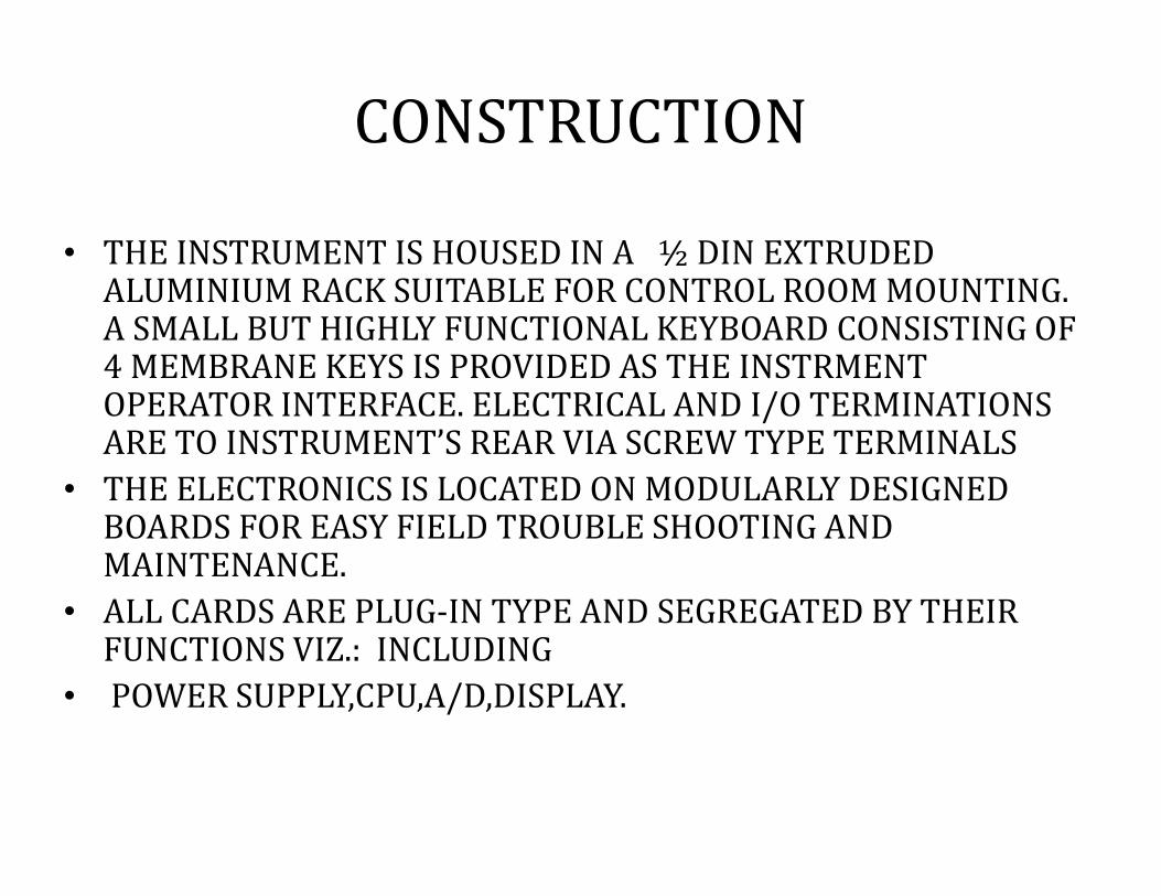
CONSTRUCTION
• THE INSTRUMENT IS HOUSED IN A ½ DIN EXTRUDED ALUMINIUM RACK SUITABLE FOR CONTROL ROOM MOUNTING. A SMALL BUT HIGHLY FUNCTIONAL KEYBOARD CONSISTING OF 4 MEMBRANE KEYS IS PROVIDED AS THE INSTRMENT OPERATOR INTERFACE. ELECTRICAL AND I/O TERMINATIONS ARE TO INSTRUMENT’S REAR VIA SCREW TYPE TERMINALS
• THE ELECTRONICS IS LOCATED ON MODULARLY DESIGNED BOARDS FOR EASY FIELD TROUBLE SHOOTING AND MAINTENANCE.
• ALL CARDS ARE PLUG-IN TYPE AND SEGREGATED BY THEIR FUNCTIONS VIZ.: INCLUDING
• POWER SUPPLY,CPU,A/D,DISPLAY.

SPECIFICATIONS :
• 1.PROCESS INPUT :0-20 K OHMS
• 2.DISPLAY : 2* 4-DIGIT,7 –SEGMENT LEDS,
• 3.POWER SUPPLY: 90V-270V AC,50 HZ
• 4. OVER RANGE : “OPEN” INDICATION
• 5.SET POINTS: HIGH AND LOW
• 6.RELAY OUTPUTS : ALARM RELAYS CHANGEOVER TYPE,DPDT,POTENTIAL FREE,RATING 5A,240V AC,RESISTIVE LOADS, 2 COMMON RELAY OUTPUTS.
• 7.COMMUNICATIONS : RS-232-C SERIAL PORT.
• 8.SCANNING : AUTO-MANUAL FACILITY.
• 9.DISPLAY TIME: 1-99 SEC/CHANNEL PROGRAMMABLE.
• 10.ACCURACY: (+/-) 2% FS, (+/-) 1 DIGIT.
• 11.AMBIENT TEMP.: 10-50 DEGREE CENTIGRADE .
• 12.EFFECTS OF TEMPERATURE: 0.015% PER DEGREE CENTIGRADE CHANGE, REFERRED TO 25 DEGREE CENTIGRADE.
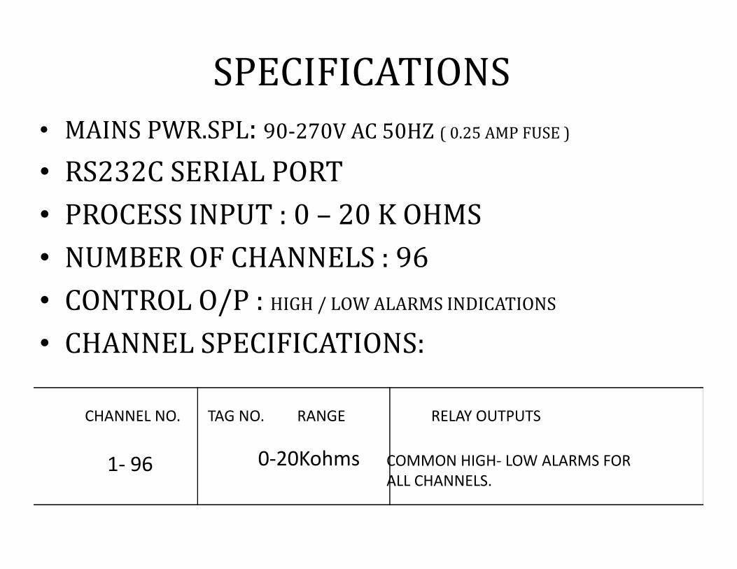
SPECIFICATIONS
• MAINS PWR.SPL: 90-270V AC 50HZ ( 0.25 AMP FUSE )
• RS232C SERIAL PORT
• PROCESS INPUT : 0 – 20 K OHMS
• NUMBER OF CHANNELS : 96
• CONTROL O/P : HIGH / LOW ALARMS INDICATIONS
• CHANNEL SPECIFICATIONS:
CHANNEL NO. TAG NO. RANGE RELAY OUTPUTS
1- 96 0-20Kohms COMMON HIGH- LOW ALARMS FOR
ALL CHANNELS.
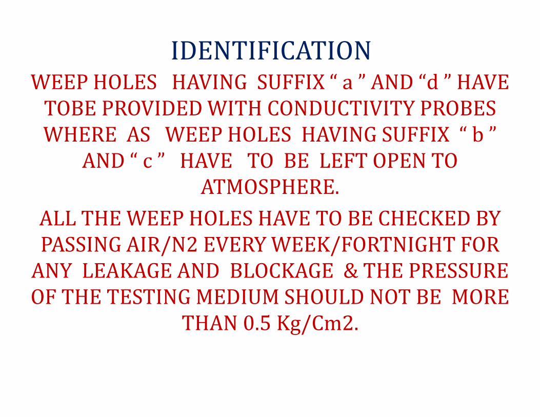
IDENTIFICATIONWEEP HOLES HAVING SUFFIX “ a ” AND “d ” HAVE
TOBE PROVIDED WITH CONDUCTIVITY PROBES
WHERE AS WEEP HOLES HAVING SUFFIX “ b ”
AND “ c ” HAVE TO BE LEFT OPEN TO
ATMOSPHERE.
ALL THE WEEP HOLES HAVE TO BE CHECKED BY
PASSING AIR/N2 EVERY WEEK/FORTNIGHT FOR
ANY LEAKAGE AND BLOCKAGE & THE PRESSURE
OF THE TESTING MEDIUM SHOULD NOT BE MORE
THAN 0.5 Kg/Cm2.

WEEPHOLE MONITORING POINTS
73
a
73b
72c 72a 72b72d
72f72e
71a71d 71b71c
70b70a
70d69a 69b 70c
69d 69c 68b 68a
51a 52b 52d 51d 51b 51c
61d
61b61
a61c
60b 60a60e60f
60c60d
Ch no
73
72
71
70
69
61
605959a 59b
52a 52c53c53a
53d
53b
51
52
53
68c68d68
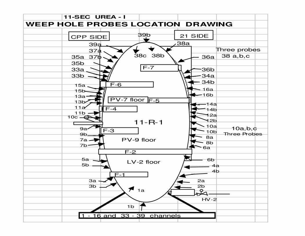
11-SEC UREA - I
WEEP HOLE PROBES LOCATION DRAWING
38 a,b,c
F-7 FLOOR
39a
37a
37b 22c 22b
F-6
36a
36b
34a
34b
F-5
F-4
15a
15b
13a
13b
11a
11b
14a
14b
12a
12b
10a
10b
8a
8b
F-7
F-6
F-5
F-4
F-3
1b
HV-2
3a
3b
F-1
5a
5b
9a
9b
7a
7b
F-2
4a
4b
6b
6a
1 - 16 and 33 - 39 channels
39bCPP SIDE 21 SIDE
10a,b,c
38c 38b
Three probes
Three Probes
16a
16b
38a
35a
35b
33a
33b
PV-7 floor
11-R-1
PV-9 floor
LV-2 floor
2a
2b1a
10c
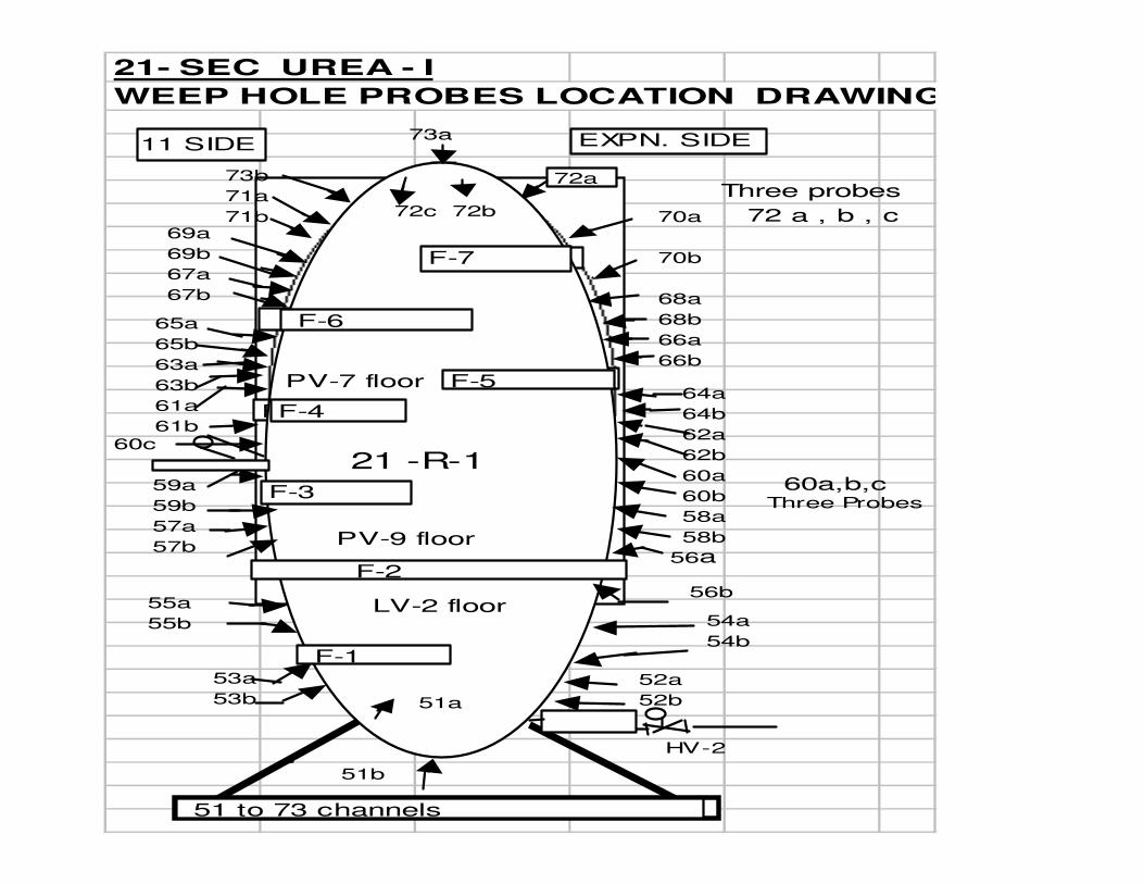
21- SEC UREA - I
WEEP HOLE PROBES LOCATION DRAWING
F-7 FLOOR
73b
71a
71b 22c 22b
72a
F-6
70a
70b
68a
68b
66a
66b
F-5
F-4
65a
65b
63a
63b
61a
61b
64a
64b
62a
62b
60a
60b
58a
58b
F-7
F-6
F-5
F-4
F-3
51b
HV-2
53a
53b
F-1
55a
55b
59a
59b
57a
57b
F-2
54a
54b
56b
56a
73a11 SIDE EXPN. SIDE
60a,b,c
72c 72b
Three probes
Three Probes
60c
52a
52b51a
69a
69b
67a
67b
72 a , b , c
LV-2 floor
PV-9 floor
PV-7 floor
21 -R-1
51 to 73 channels
CHECKING OF WEEP HOLES
THE WEEPHOLES CAN ALSO BE CHECKED INDIVIDUALLY
BY DISCONNECTING THE OUTCOMMING TUBES AT A
SUITABLE FREQUENCY TO BE DECIDED BASED
ON ACTUAL EXPERIENCE.
SINCE TWO WEEPHOLES ARE CONNECTED INTERNALLY,
PAIR OF SUCH WEEPHOLES ARE TO BE IDENTIFIED
(TIME TO TIME ) IN SUCH A WAY THAT OUT OF THE
TWO , ONE IS TO BE CONNECTED TO HEADER L2
( THE N2 FEEDING HEADER TO WEEPHOLES )AND THE
SECOND ONE TO HEADER L3 FOR CONNECTING RETURN
TO THE BUBBLER.

TO CHECK AND REMOVE THE CHOKING OF EXISTING WEEPHOLES
N2
L1 L2
L3
V1V2
V4
V3
1
2
3
4
A
B
C
D
ACKNOWLEDGEMENT OF LEAKAGE
NORMALLY WHEN THE LEAKAGE STARTS, IT COMES OUT IN THE
FORM OF LIQUID AND GASES AS THEY ARE HOT. THE LEAKY
MAY SOLIDIFY AT PLACES IN THE N2 HEADER WHERE THE
TEMPERATURE IS LOW. THAT IS WHY WEEP HOLE
NOZZLES ARE KEPT SHORT AND OPENED TO ATMOSPHERE FOR
EASY VISIBILITY.
SINCE THE N2 IS ALLOWED TO PASS INBETWEEN THE LINER
AND SHELL , THE PRESSURE OF N2 MUST NOT EXCEED MORE
THAN 0.5 Kg/Cm2. EXCESS PRESSURE MAY DAMAGE THE
LINER WHEN THE EQUIPMENT IS IN DEPRESSURISED
CONDITION.
WHY AND WHERE THIS SYSTEM IS
NEEDEDHIGH PRESSURE
CORROSIVE ENVIORENMENT
LINER USED SURFACE
LINER USED IN UREA – 1 :
V-1 : SS-316L IS USED
E-5 : SS-316L IS USED
E-1 : 2-RE-69 IS USED
IN REACTOR SS-316L MODIFIED IS USEDNOW WE WILL SEE DIFFERENT MATERIAL COMPOSITIONS
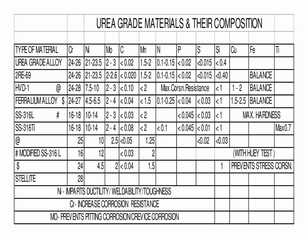
TYPE OF MATERIAL Cr Ni Mo C Mn N P S Si Cu Fe Ti
UREA GRADE ALLOY 24-26 21-23.5 2 - 3 < 0.02 1.5-2 0.1-0.15 < 0.02 <0.015 < 0.4
2RE-69 24-26 21-23.5 2-2.6 < 0.020 1.5-2 0.1-0.15 < 0.02 <0.015 <0.40 BALANCE
HVD-1 @ 24-28 7.5-10 2 - 3 < 0.10 < 2 < 1 1 - 2 BALANCE
FERRALIUM ALLOY $ 24-27 4.5-6.5 2 - 4 < 0.04 < 1.5 0.1-0.25 < 0.04 < 0.03 < 1 1.5-2.5 BALANCE
SS-316L # 16-18 10-14 2 - 3 < 0.03 < 2 < 0.045 < 0.03 < 1
SS-316Ti 16-18 10-14 2 - 4 < 0.08 < 2 < 0.1 < 0.045 < 0.01 < 1 Max0.7
@ 25 10 2.5 <0.05 1.25 <0.02 <0.03
# MODIFIED SS-316 L 16 12 < 0.03 2
$ 24 4.5 2 < 0.04 1.5 1
STELLITE 28
UREA GRADE MATERIALS & THEIR COMPOSITION
PREVENTS STRESS CORSN.
(WITH HUEY TEST )
MAX. HARDNESS
Max.Corsn.Resistance
Ni - IMPARTS DUCTILITY/ WELDABILITY/TOUGHNESS
MO- PREVENTS PITTING CORROSION/CREVICE CORROSION
Cr- INCREASE CORROSION RESISTANCE

MICROGENIE-SCAN
THE MICROGENIE –SCAN IS A MICROPROCESSOR BASED
SCANNER WHICH SCANS THE PROCESS VALUE AT
VARIOUS CHANNELS.THE CHANNELS CAN BE SCANNED
IN AUTO MODE OR A DESIRED CHANNEL CAN BE
PERMANENTLY VIEWED IN THE MANUAL MODE.THE
PHILOSOPHY OF THE DESIGN HAS BEEN TO MAKE
PROGRAMMING A VERY SIMPLE TASK EVEN FOR THE
SHOP-FLOOR PERSONNEL.THIS HAS BEEN ACHIEVED BY
USING A USER-FRIENDLY SCROLLING FUNCTION WHICH
PROMPTS AN OPERATOR TO GO THROUGH A SEQUENCE
OF PROGRAMMING STEPS.
INPUT CONNECTIONS
INPUT CONNECTIONS ARE MADE VIA A TERMI
QUICK ARRANGEMENT. THE TERMI-QUICK
ARRANGEMENT IS A FLATE –CABLE WITH
LOCKING TYPE CONNECTORS AT EITHER END
AND A SENSOR TERMINATION BOARD.
THE INSTRUMENT CAN BE REMOVED FROM THE
PANEL BY JUST DISCONNECTING ITS FLAT CABLE
CONNECTOR.YOU NEED NOT DISCONNECT THE
SENSOR CABLING.
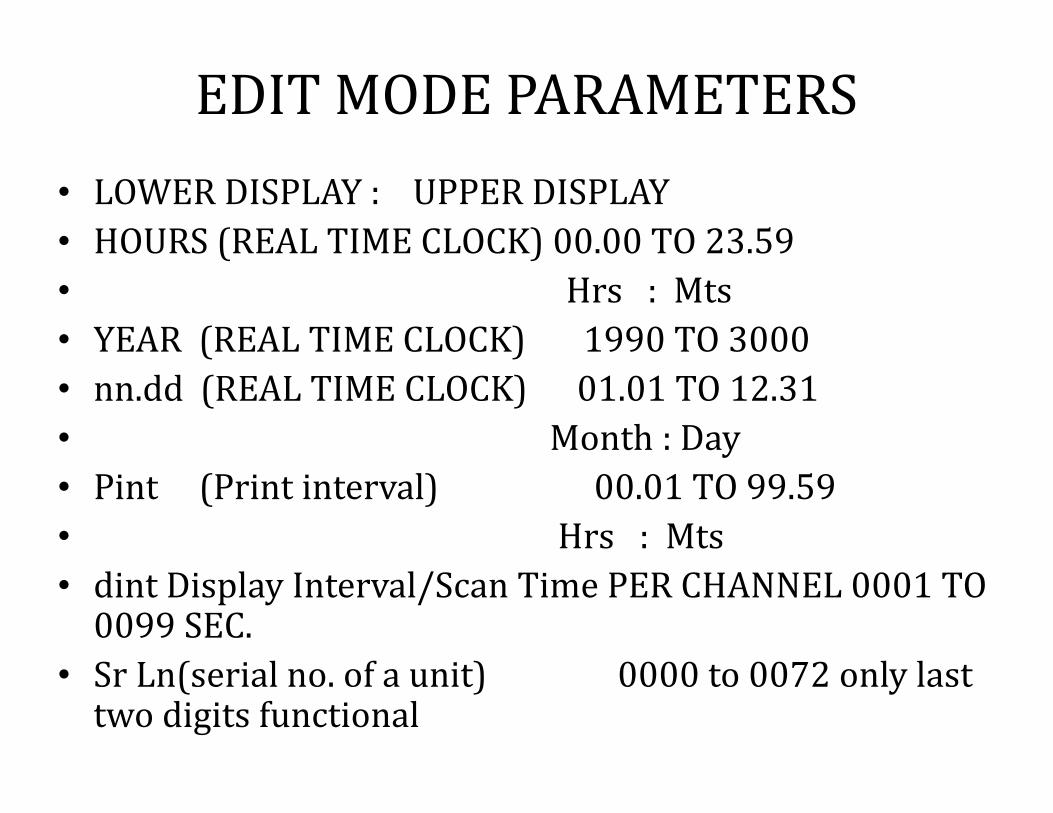
EDIT MODE PARAMETERS
• LOWER DISPLAY : UPPER DISPLAY
• HOURS (REAL TIME CLOCK) 00.00 TO 23.59
• Hrs : Mts
• YEAR (REAL TIME CLOCK) 1990 TO 3000
• nn.dd (REAL TIME CLOCK) 01.01 TO 12.31
• Month : Day
• Pint (Print interval) 00.01 TO 99.59
• Hrs : Mts
• dint Display Interval/Scan Time PER CHANNEL 0001 TO 0099 SEC.
• Sr Ln(serial no. of a unit) 0000 to 0072 only last two digits functional

LIMIT MODE PARAMETERS
• LOWER DISPLAY UPPER DISPLAY
• AH / AL For High / Low setpoint
• gH / gL on/off relay diffreential gap
• Calibration mode parameters
• Z Calibration at zero side/Lower value of Specified range
• S Calibration at Span side / upper value of specified range
• IH /OH SKIP / UNSKIP A CHANNEL

Today still too many accidents (ruptures, explosions)
of high-pressure equipment items in the urea industry
do occur…
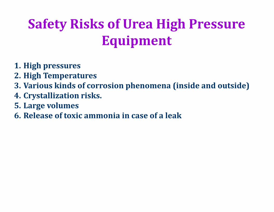
Safety Risks of Urea High Pressure
Equipment
1. High pressures
2. High Temperatures
3. Various kinds of corrosion phenomena (inside and outside)
4. Crystallization risks.
5. Large volumes
6. Release of toxic ammonia in case of a leak

Integrity of carbon steel pressure
bearing wall can be threatened by:
1. Carbamate corrosion due to damage of protective layer with
(corrosion rate 1000 mm/year):
2. An early and reliable detection is a must.
3. Stress corrosion cracking behind loose liner when water and
contaminants are present.
4. Stress corrosion cracking from outside when water and
contaminants are present
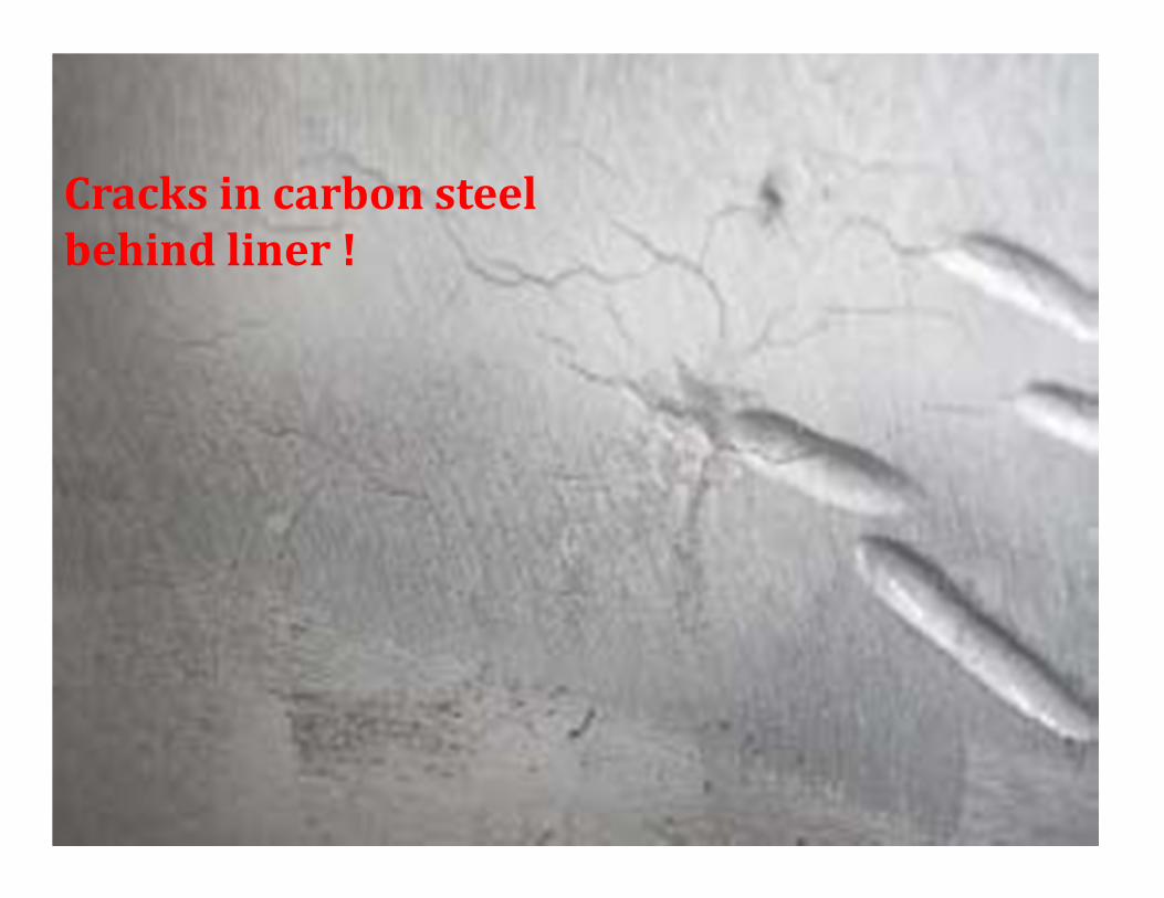
Cracks in carbon steel
behind liner !
Do realise
Typical lifetime of the 316L Urea Grade protective
layer of a urea reactor is 20-30 years
While
Typical lifetime of a urea plant is 40-50 years.
Thus
Every urea reactor will finally operate close to the
end of lifetime conditions of the protective layer
Meaning that at a certain moment a leak in the
protective layer is nearly unavoidable
Gas phase leak
CO2 and NH3 gases flashing forming carbamate solids
below 60oC
Liquid phase leak without urea
1. Carbamate flashes forming CO2 and NH3 gases
2. No carbamate solids above 60oC
Liquid phase leak with urea
1. Carbamate flashes forming CO2 and NH3 gases
2. No carbamate solids above 60oC
3. BUT urea solids are present below 133oC and also above
133oC urea partly decomposes into NH3 and HNCO but
also forms biuret, triuret etc. with even higher melting
points
Passive systems
1. Checking for vapors
2. Checking the smell of NH3
3. NH3 Reagent (color change)
4. Checking of bubbles in a dipped vessel
filled with oil
5. Conductivity
6. Infrared
All systems wait for leak to show up at the
detector, while clogging can already occur…
Weep hole monitoring by vacuum system
Advantages(Developed by Ureaknowhow.com
By Mr. Mark Brouwer)
1. It detects the maximum liner area (also around clips and other
failure modes like condensation corrosion, fatigue cracks, clogged
groove etc.)
2. It can be applied in every design reactor, also in case
3. no grooves are present
4. one hole is present in the liner compartment
5. clogged situations
6. It avoids risks of liner bulging and damage
7. A vacuum system allows larger distances between high-pressure
equipment items (for example with twin urea lines)
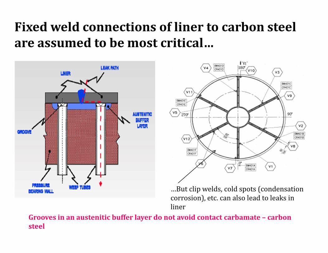
Fixed weld connections of liner to carbon steel
are assumed to be most critical…
…But clip welds, cold spots (condensation
corrosion), etc. can also lead to leaks in
liner
Grooves in an austenitic buffer layer do not avoid contact carbamate – carbon
steel
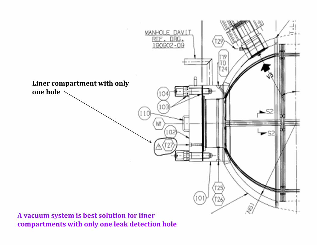
Liner compartment with only
one hole
A vacuum system is best solution for liner
compartments with only one leak detection hole
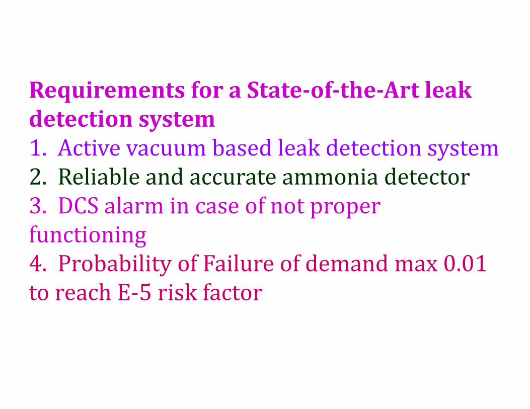
Requirements for a State-of-the-Art leak
detection system
1. Active vacuum based leak detection system
2. Reliable and accurate ammonia detector
3. DCS alarm in case of not proper
functioning
4. Probability of Failure of demand max 0.01
to reach E-5 risk factor
Further requirements for quick and easy locating of
leak
1. The possibility to check for open circuits (avoid clogging
risks)
2. The possibility to identify the leaking liner circuit in
order to minimize downtime to locate and repair the leak
3. To have information about the leak size (in order to be
able to select and prepare the right and most suitable
method to pinpoint the leak to minimize the downtime to
locate and repair the leak)
4. To be able to introduce a leak detection tracer for
pinpointing the leak .
5. To distinguish false air leaks from real liner leak
1. An active, vacuum based leak detection system
2. With an accurate and reliable ammonia detector
3. Meeting the Probability of Failure on Demand
requirement of maximum 0.01.
4. The DCS operator will be warned in case there is
5. A lack of vacuum pressure
6. Clogging
7. Malfunctioning of the ammonia detector
8. And of course a liner leak is present
Features of “UreaKnowHow.com “Leak
Detection System
Benefits Boreal Laser Ammonia Detector
1. Safe
2. Very accurate
3. NH3 specific
4. Self calibrating
5. No maintenance
6. No consumables
7. No memory effect
8. No saturation effect
9. Provides alarm when not functioning
HELIUM LEAK DETECTION
A Helium Leak detector, also known as a Mass
Spectrometer Leak Detector (MSLD), is used to locate
and measure the size ofleaks into or out of a system or
containing device. The tracer gas, helium, is
introduced to a test part that is connected to the leak
detector. Helium is the best choice of tracer gas to find
leaks for a number of reasons. It is non-toxic, inert,
non-condensable, non-flammable and not normally
present in the atmosphere at more than trace amounts
(5 ppm). Due to its small atomic size, helium passes
easily through leaks. The only molecule smaller than
Helium is Hydrogen which is not inert. It is also
relatively inexpensive and is available in various size
cylinders.
Helium Leak Detection
A Helium Leak detector, also known as a Mass
Spectrometer Leak Detector (MSLD), is used to locate and
measure the size of leaks into or out of a system or
containing device. The tracer gas, helium, is introduced to
a test part that is connected to the leak detector. The
helium leaking through the test part enters through the
system and this partial pressure is measured and the
results are displayed on a meter.
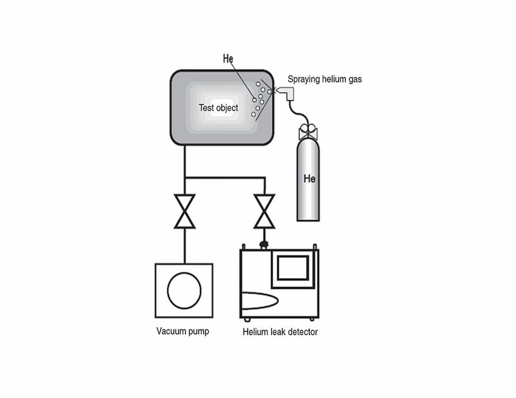
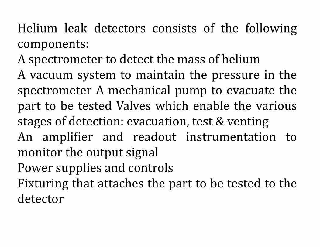
Helium leak detectors consists of the following
components:
A spectrometer to detect the mass of helium
A vacuum system to maintain the pressure in the
spectrometer A mechanical pump to evacuate the
part to be tested Valves which enable the various
stages of detection: evacuation, test & venting
An amplifier and readout instrumentation to
monitor the output signal
Power supplies and controls
Fixturing that attaches the part to be tested to the
detector
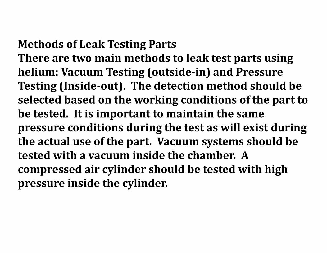
Methods of Leak Testing Parts
There are two main methods to leak test parts using
helium: Vacuum Testing (outside-in) and Pressure
Testing (Inside-out). The detection method should be
selected based on the working conditions of the part to
be tested. It is important to maintain the same
pressure conditions during the test as will exist during
the actual use of the part. Vacuum systems should be
tested with a vacuum inside the chamber. A
compressed air cylinder should be tested with high
pressure inside the cylinder.
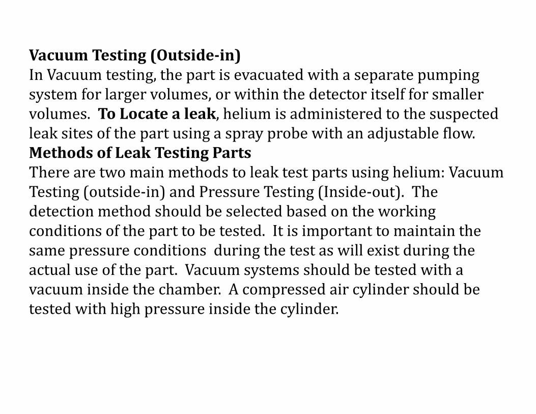
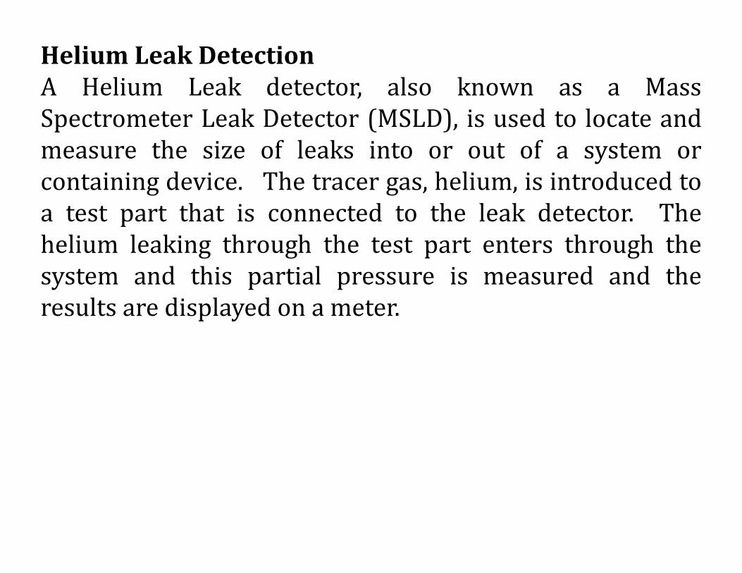
Vacuum Testing (Outside-in)
In Vacuum testing, the part is evacuated with a separate pumping
system for larger volumes, or within the detector itself for smaller
volumes. To Locate a leak, helium is administered to the suspected
leak sites of the part using a spray probe with an adjustable flow.
Methods of Leak Testing Parts
There are two main methods to leak test parts using helium: Vacuum
Testing (outside-in) and Pressure Testing (Inside-out). The
detection method should be selected based on the working
conditions of the part to be tested. It is important to maintain the
same pressure conditions during the test as will exist during the
actual use of the part. Vacuum systems should be tested with a
vacuum inside the chamber. A compressed air cylinder should be
tested with high pressure inside the cylinder.
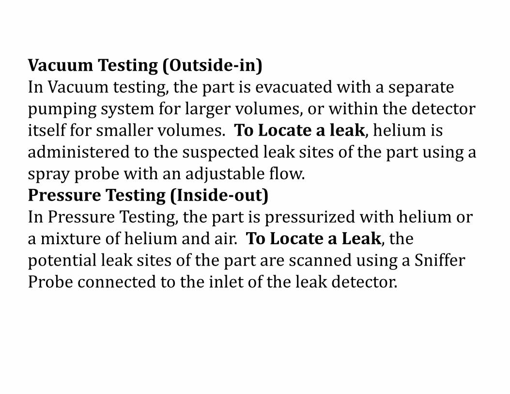
Vacuum Testing (Outside-in)
In Vacuum testing, the part is evacuated with a separate
pumping system for larger volumes, or within the detector
itself for smaller volumes. To Locate a leak, helium is
administered to the suspected leak sites of the part using a
spray probe with an adjustable flow.
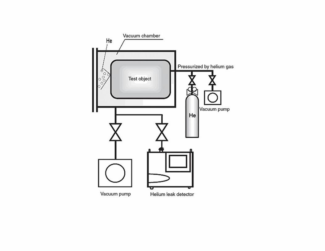
Pressure Testing (Inside-out)
In Pressure Testing, the part is pressurized with helium or
a mixture of helium and air. To Locate a Leak, the
potential leak sites of the part are scanned using a Sniffer
Probe connected to the inlet of the leak detector.
Leak Testing Vacuum Systems & Pressure
Systems
Vacuum systems and pressure systems should be
leak tested under the same conditions as their
operational conditions. Vacuum systems are tested
with a portable leak detector. The leak detector is
connected to the line of the vacuum pump. Helium
is applied to the potential leak site using a spary
prove. If a leak exists, helium enters the system and
quickly diffuses through it. The leak detector
should respond within seconds. Pressure
systems can be charged with helium or a mixture
of helium and nitrogen. The leak testing is
performed by using a Sniffer probe.
Helium Leak Detection Applications
Quality control of production parts and
assemblies using helium leak detectors can
help assure the integrity of your production
process. Typical examples include:
hermetically sealed packages, valves, Mani
folding, seals, vacuum vessels and systems,
medical devices, high purity piping, brake
lines, fuel lines, hydraulic lines, refrigeration
assemblies, radiators, heat exchangers,
condensers, storage tanks.
Maintenance of Systems
Industrial process tools that use vacuum systems or
pressure systems must be tested to check for
occasional leaks. This can be part of preventative
maintenance or in the event of an unexpected
failure. Typical examples of vacuum systems
include: Vacuum furnaces, vacuum coaters, electron
microscopes, glove boxes, linear accelerators,
electron beam and ion beam process equipment,
semiconductor process equipment, laser process
equipment. Typical examples of pressurized
systems include: power plants, gas handling
systems, bioreactors, liquid gas facilities,
underground tanks, underground cables and pipes.