

Human Spaceflight Structures Engineering Internship
Joshua PetersonNASA’s Johnson Space Center – Spring 2017
University Science Research Association (USRA)
05/11/2017 1
https://ntrs.nasa.gov/search.jsp?R=20170004601 2018-07-06T18:05:24+00:00Z

Content
• Background
• Lightweight External Inflatable Airlock (LEIA)
• Cislunar Habitat Module
• Artificial Gravity Study
• Additional Projects
• Conclusions
05/11/2017 2
Content
• Background
• Lightweight External Inflatable Airlock (LEIA)
• Cislunar Habitat Module
• Artificial Gravity Study
• Additional Projects
• Conclusions
05/11/2017 3
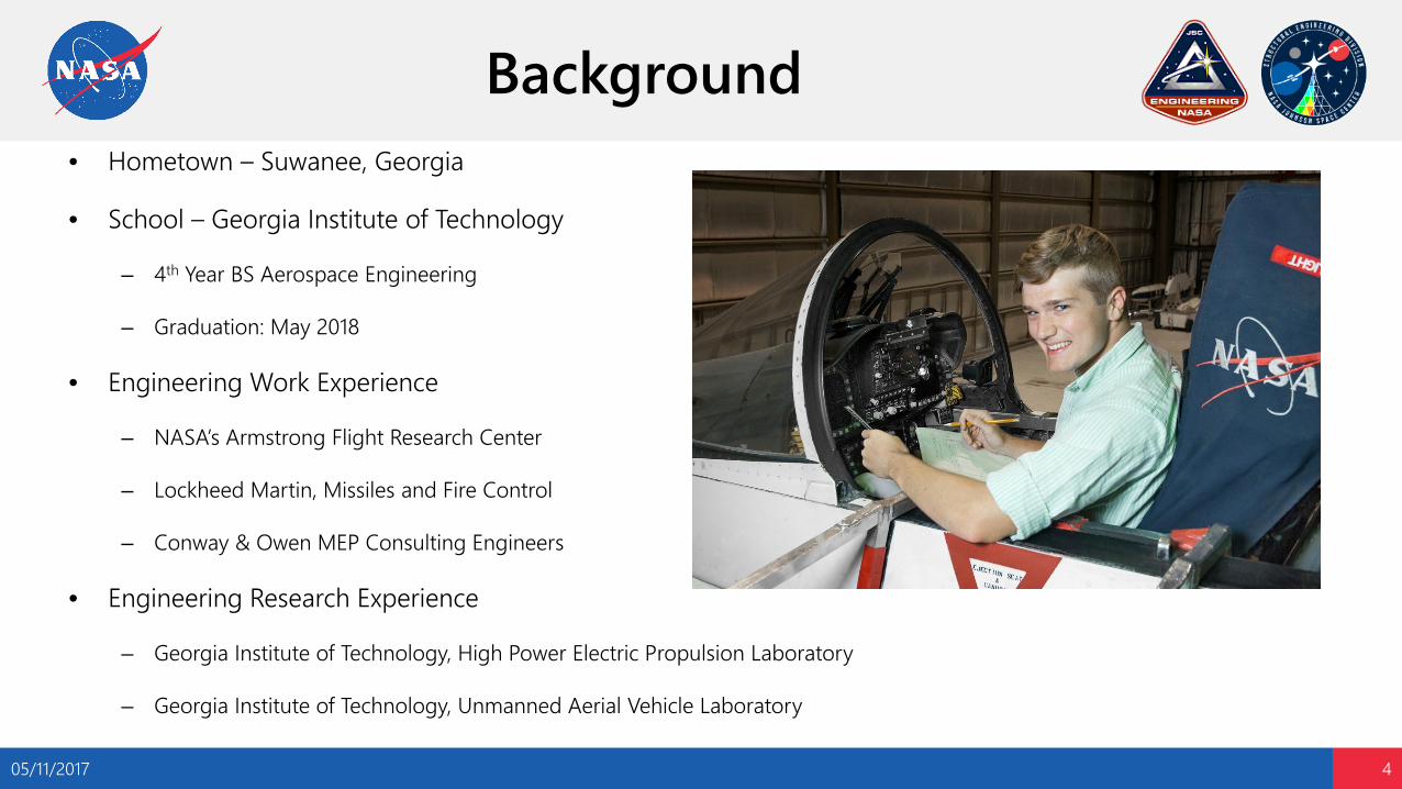
Background• Hometown – Suwanee, Georgia
• School – Georgia Institute of Technology
– 4th Year BS Aerospace Engineering
– Graduation: May 2018
• Engineering Work Experience
– NASA’s Armstrong Flight Research Center
– Lockheed Martin, Missiles and Fire Control
– Conway & Owen MEP Consulting Engineers
• Engineering Research Experience
– Georgia Institute of Technology, High Power Electric Propulsion Laboratory
– Georgia Institute of Technology, Unmanned Aerial Vehicle Laboratory
05/11/2017 4

Content
• Background
• Lightweight External Inflatable Airlock (LEIA)
• Cislunar Habitat Module
• Artificial Gravity Study
• Additional Projects
• Conclusions
05/11/2017 5
Lightweight External Inflatable Airlock (LEIA) – Overview
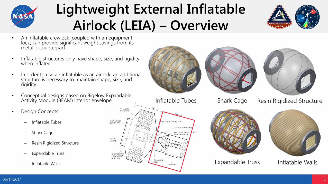
• An inflatable crewlock, coupled with an equipment lock, can provide significant weight savings from its metallic counterpart
• Inflatable structures only have shape, size, and rigidity when inflated
• In order to use an inflatable as an airlock, an additional structure is necessary to maintain shape, size, and rigidity
• Conceptual designs based on Bigelow Expandable Activity Module (BEAM) interior envelope
• Design Concepts
– Inflatable Tubes
– Shark Cage
– Resin Rigidized Structure
– Expandable Truss
– Inflatable Walls
05/11/2017 6
Inflatable Tubes Shark Cage Resin Rigidized Structure
Inflatable WallsExpandable Truss

Lightweight External Inflatable Airlock (LEIA) – Volume Analysis
05/11/2017 7
• Compared LEIA volume concepts to the Quest Joint Airlock
• Found that all LEIA concepts had plenty of volume to perform airlock procedures
• Additional Questions– Will astronauts have
trouble rotating to operate EV hatch?
– Will the extra volume in LEIA designs create problems with translation and rotation?
Inflatable TubesShark Cage Quest Joint Airlock

Lightweight External Inflatable Airlock (LEIA) – Shark Cage
• Composed of 2024-T3 aluminum tubes
• Design includes longitudinal tubes and hoop tubes that are fastened together
• Crew will receive Shark Cage in several pieces and assemble within inflatable structure
• Major Advantages– Low Mass
– High Available Volume
– Simple Manufacturing
– Simple In-Space Assembly
05/11/2017 8

Lightweight External Inflatable Airlock (LEIA) – Initial Analysis
05/11/2017 9
• Hand calculations performed on 125 lb. incidental loads located on outside of EV Hatch
• The factor of safety used was 2.25 for metallic structure
• Margins shown are for one longitudinal member with a 2.5” outer diameter and a 1.8” inner diameter
DESC. MATL SPEC SOURCE Ftu Fsu Fcy UNITS
Shark Cage Member 2024-T3 QQ-A-250/4 MMPDS-11,
3-118 64 39 42 ksi
DETAIL LOAD CASE FAILURE MODE M.S.*Shark Cage – EV Hatch
Connection 125 lbs AFT Shear Stress +High
Shark Cage – Midpoint 125 lbs AFT Compression +High
Shark Cage – Midpoint 125 lbs AFT Buckling +0.06
Shark Cage – IV Hatch Connection 125 lbs DN Compression +0.52
AFT Load Case DN Load Case
Lightweight External Inflatable Airlock (LEIA) – Initial Analysis
05/11/2017 10
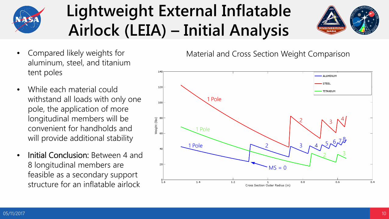
• Compared likely weights for aluminum, steel, and titanium tent poles
• While each material could withstand all loads with only one pole, the application of more longitudinal members will be convenient for handholds and will provide additional stability
• Initial Conclusion: Between 4 and 8 longitudinal members are feasible as a secondary support structure for an inflatable airlock
Material and Cross Section Weight Comparison
1 Pole
1 Pole
1 Pole
2 3 4
2 65437 8
2 3
MS = 0
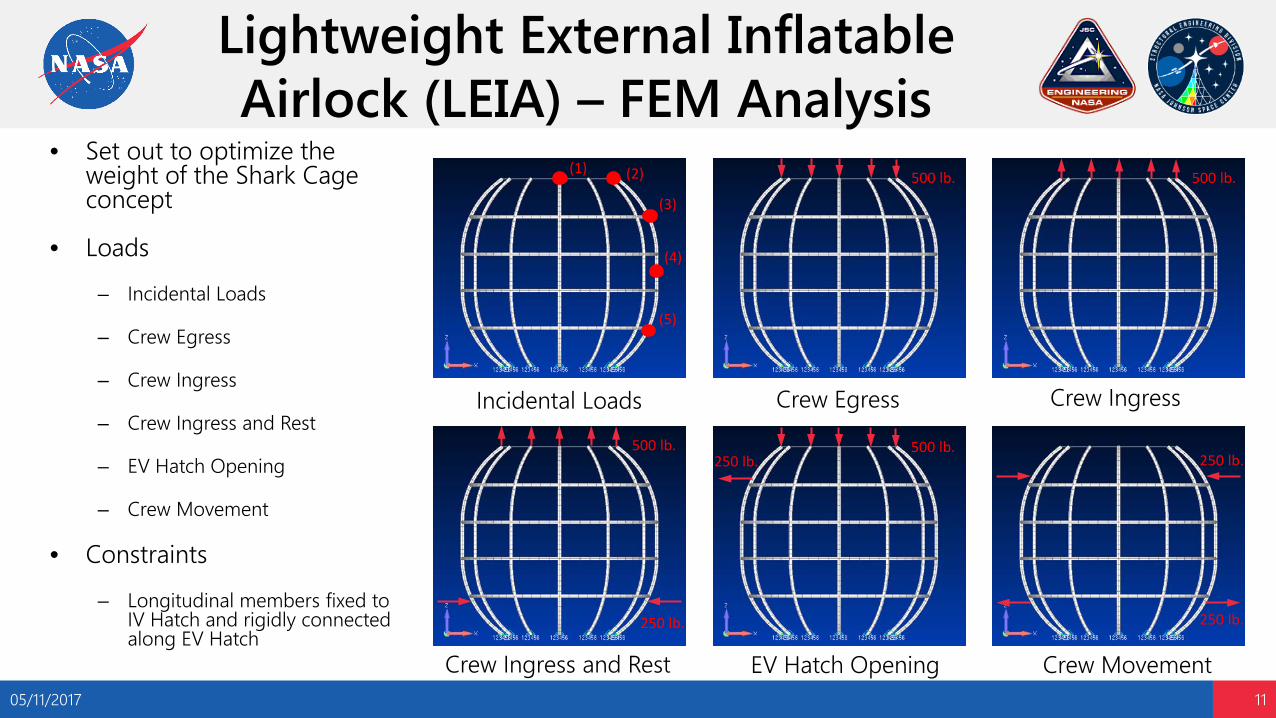
Lightweight External Inflatable Airlock (LEIA) – FEM Analysis
• Set out to optimize the weight of the Shark Cage concept
• Loads
– Incidental Loads
– Crew Egress
– Crew Ingress
– Crew Ingress and Rest
– EV Hatch Opening
– Crew Movement
• Constraints
– Longitudinal members fixed to IV Hatch and rigidly connected along EV Hatch
05/11/2017 11
(1)
(3)
(4)
(5)
(2) 500 lb. 500 lb.
500 lb.
250 lb.
500 lb. 250 lb.
250 lb.
250 lb.
Crew IngressIncidental Loads
Crew MovementEV Hatch OpeningCrew Ingress and Rest
Crew Egress

Lightweight External Inflatable Airlock (LEIA) – Design Study
• How does the stress change with different geometries?
• Task: Optimize the Shark Cage design• Design Variables:
– Cross Section Outer Diameter• 5/8”, 3/4”, 1”, 1.5”, 2”
– Number of Longitudinal Members• 6, 8, 12, 16
– Number of Circular Members• 2, 4, 5
05/11/2017 12
-1-0.5
00.5
11.5
5 7 9 11 13 15 17
M.S
.
Number of Longitudinal Members
Margin of Safety v. Longitudinal Members - 2 Hoops
OD 0.675"
OD 0.75"
OD 1.0"
OD 1.5"
-2
0
2
4
6
5 7 9 11 13 15 17
M.S
.
Number of Longitudinal Members
Margin of Safety v. Longitudinal Members - 4 Hoops
OD 0.675"
OD 0.75"
OD 1.0"
OD 1.5"
-2
0
2
4
5 7 9 11 13 15 17
M.S
.
Number of Longitudinal Members
Margin of Safety v. Longitudinal Members - 5 Hoops
OD 0.675"
OD 0.75"
OD 1.0"
OD 1.5"
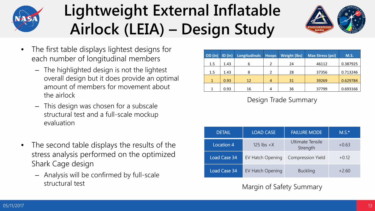
Lightweight External Inflatable Airlock (LEIA) – Design Study
• The first table displays lightest designs for each number of longitudinal members– The highlighted design is not the lightest
overall design but it does provide an optimal amount of members for movement about the airlock
– This design was chosen for a subscale structural test and a full-scale mockup evaluation
• The second table displays the results of the stress analysis performed on the optimized Shark Cage design– Analysis will be confirmed by full-scale
structural test
05/11/2017 13
DETAIL LOAD CASE FAILURE MODE M.S.*
Location 4 125 lbs +X Ultimate Tensile Strength +0.63
Load Case 34 EV Hatch Opening Compression Yield +0.12
Load Case 34 EV Hatch Opening Buckling +2.60
OD (in) ID (in) Longitudinals Hoops Weight (lbs) Max Stress (psi) M.S.
1.5 1.43 6 2 24 46112 0.387925
1.5 1.43 8 2 28 37356 0.713246
1 0.93 12 4 31 39269 0.629784
1 0.93 16 4 36 37799 0.693166
Design Trade Summary
Margin of Safety Summary
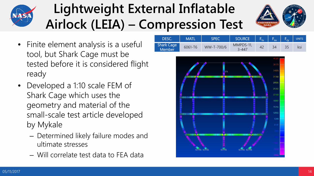
Lightweight External Inflatable Airlock (LEIA) – Compression Test
• Finite element analysis is a useful tool, but Shark Cage must be tested before it is considered flight ready
• Developed a 1:10 scale FEM of Shark Cage which uses the geometry and material of the small-scale test article developed by Mykale– Determined likely failure modes and
ultimate stresses– Will correlate test data to FEA data
05/11/2017 14
DESC. MATL SPEC SOURCE Ftu Fsu Fcy UNITS
Shark Cage Member 6061-T6 WW-T-700/6 MMPDS-11,
3-447 42 34 35 ksi
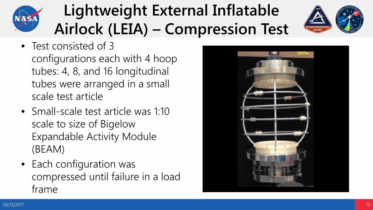
Lightweight External Inflatable Airlock (LEIA) – Compression Test
05/11/2017 15
• Test consisted of 3 configurations each with 4 hoop tubes: 4, 8, and 16 longitudinal tubes were arranged in a small scale test article
• Small-scale test article was 1:10 scale to size of Bigelow Expandable Activity Module (BEAM)
• Each configuration was compressed until failure in a load frame

Lightweight External Inflatable Airlock (LEIA) – Compression Test
05/11/2017 16
Test ArticleConfiguration
Number of Longitudinals
Expected Yield
Strength
Expected Ultimate Strength
Expected Buckling Strength
Expected Max Elastic Deflection
ObservedFailure Load
A 4 375 lbf 500 lbf 625 lbf 0.0569 in 800 lbf
B 8 1125 lbf 1375 lbf 1500 lbf 0.0307 in 2500 lbf
C 16 3000 lbf 3875 lbf 3500 lbf 0.0350 in 3000 lbf
• The small-scale compression test showed my FEA was conservative and needs to be tuned to represent real-world results
• Error between FEA and Test Data: 𝜀𝜀 = 𝑂𝑂𝑂𝑂𝑂𝑂𝑂𝑂𝑂𝑂𝑂𝑂𝑂𝑂𝑂𝑂 −𝐸𝐸𝐸𝐸𝐸𝐸𝑂𝑂𝐸𝐸𝐸𝐸𝑂𝑂𝑂𝑂
𝐸𝐸𝐸𝐸𝐸𝐸𝑂𝑂𝐸𝐸𝐸𝐸𝑂𝑂𝑂𝑂X 100
– Configuration A: 60% (UTS)– Configuration B: 67% (Buckling)– Configuration C: -23% (UTS)
• Possible sources of discrepancy– All members except EV Hatch connections in
FEA were clamped-clamped configuration (did not account for fasteners and distributed load interactions)
– EV hatch longitudinal connections in FEA were allowed to rotate
– Did not take into account the plastic connectors used in assembly of test article
Analytical Prediction
0
500
1000
1500
2000
2500
3000
3500
-4.50E-01-4.00E-01-3.50E-01-3.00E-01-2.50E-01-2.00E-01-1.50E-01-1.00E-01-5.00E-020.00E+00
Load
(lbf
)
Vertical Displacement (in)
Shark Cage: Load-Displacement Data
4C 4L
4C 8L
4C 16L
Ultimate Tensile Strength Failure
Local Buckling FailurePlastic Fastener UTS Failure

Lightweight External Inflatable Airlock (LEIA) – Future Work
• Refine FEM for better correlation with test data
• Develop and test full-scale mock-ups of Inflatable Tube and Shark Cage design
• Continue developing resin rigidizable technology
• Launch and test final concept on ISS
05/11/2017 17

Content
• Background
• Lightweight External Inflatable Airlock (LEIA)
• Cislunar Habitat Module
• Artificial Gravity Study
• Additional Projects
• Conclusions
05/11/2017 18

Cislunar Habitat Module –Overview
• Working to develop next generation space station habitat modules for cislunar space
• ISS era modules carried launch loads and instruments around the outer edge of the module
• Future cislunar modules will carry launch loads and instruments in the center of the module core structure much like a fighter jet
05/11/2017 19
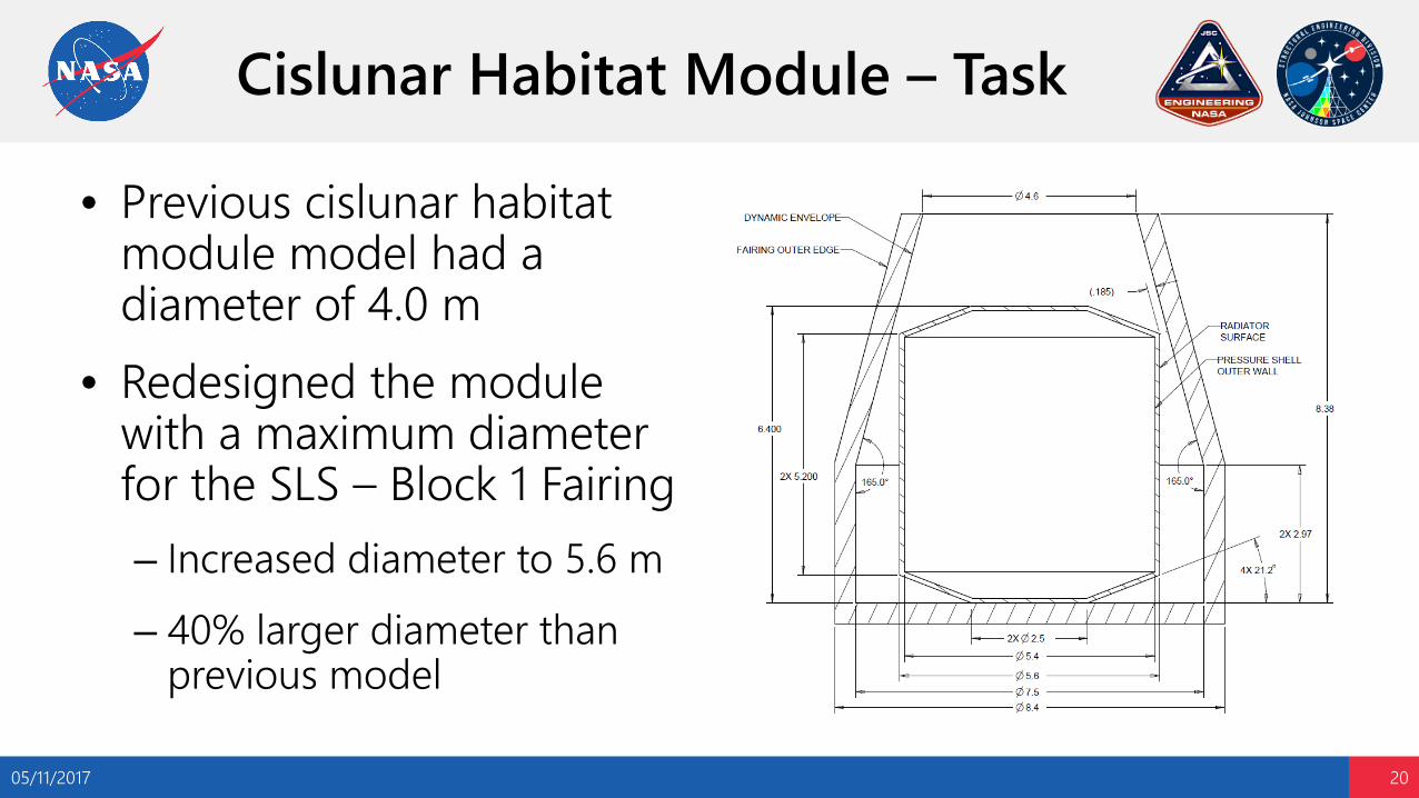
Cislunar Habitat Module – Task
• Previous cislunar habitat module model had a diameter of 4.0 m
• Redesigned the module with a maximum diameter for the SLS – Block 1 Fairing– Increased diameter to 5.6 m– 40% larger diameter than
previous model
05/11/2017 20
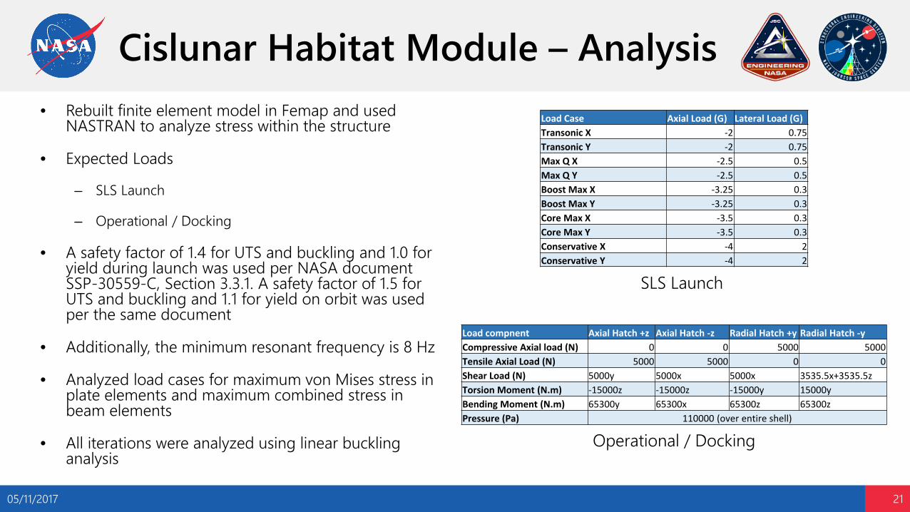
Cislunar Habitat Module – Analysis• Rebuilt finite element model in Femap and used
NASTRAN to analyze stress within the structure
• Expected Loads
– SLS Launch
– Operational / Docking
• A safety factor of 1.4 for UTS and buckling and 1.0 for yield during launch was used per NASA document SSP-30559-C, Section 3.3.1. A safety factor of 1.5 for UTS and buckling and 1.1 for yield on orbit was used per the same document
• Additionally, the minimum resonant frequency is 8 Hz
• Analyzed load cases for maximum von Mises stress in plate elements and maximum combined stress in beam elements
• All iterations were analyzed using linear buckling analysis
05/11/2017 21
Load compnent Axial Hatch +z Axial Hatch -z Radial Hatch +y Radial Hatch -yCompressive Axial load (N) 0 0 5000 5000Tensile Axial Load (N) 5000 5000 0 0Shear Load (N) 5000y 5000x 5000x 3535.5x+3535.5zTorsion Moment (N.m) -15000z -15000z -15000y 15000yBending Moment (N.m) 65300y 65300x 65300z 65300zPressure (Pa) 110000 (over entire shell)
Load Case Axial Load (G) Lateral Load (G)Transonic X -2 0.75Transonic Y -2 0.75Max Q X -2.5 0.5Max Q Y -2.5 0.5Boost Max X -3.25 0.3Boost Max Y -3.25 0.3Core Max X -3.5 0.3Core Max Y -3.5 0.3Conservative X -4 2Conservative Y -4 2
SLS Launch
Operational / Docking
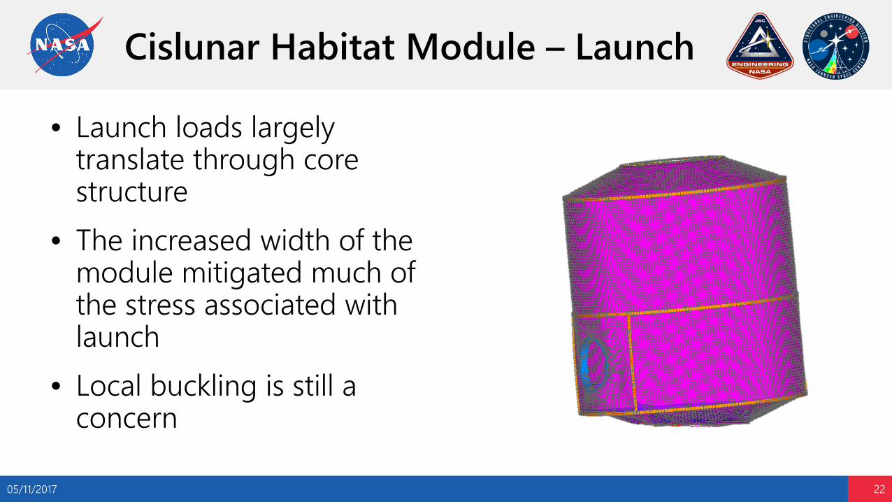
Cislunar Habitat Module – Launch
• Launch loads largely translate through core structure
• The increased width of the module mitigated much of the stress associated with launch
• Local buckling is still a concern
05/11/2017 22

Cislunar Habitat Module –Operational / Docking
• Operational and docking loads are largely translate through the pressure shell
• The increased width of the module greatly increased the stress associated with maintaining atmospheric pressure within the module
• Docking loads and moments are less of a concern than operating pressure
05/11/2017 23

Cislunar Habitat Module – Major Design Changes
05/11/2017 24
Fine Tuned Plate Thickness
Removed Waffle Shell
SymmetricalCore Structure
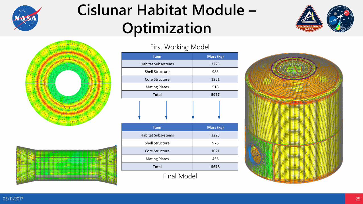
Cislunar Habitat Module –Optimization
05/11/2017 25
Item Mass (kg)
Habitat Subsystems 3225
Shell Structure 983
Core Structure 1251
Mating Plates 518
Total 5977
Item Mass (kg)
Habitat Subsystems 3225
Shell Structure 976
Core Structure 1021
Mating Plates 456
Total 5678
First Working Model
Final Model
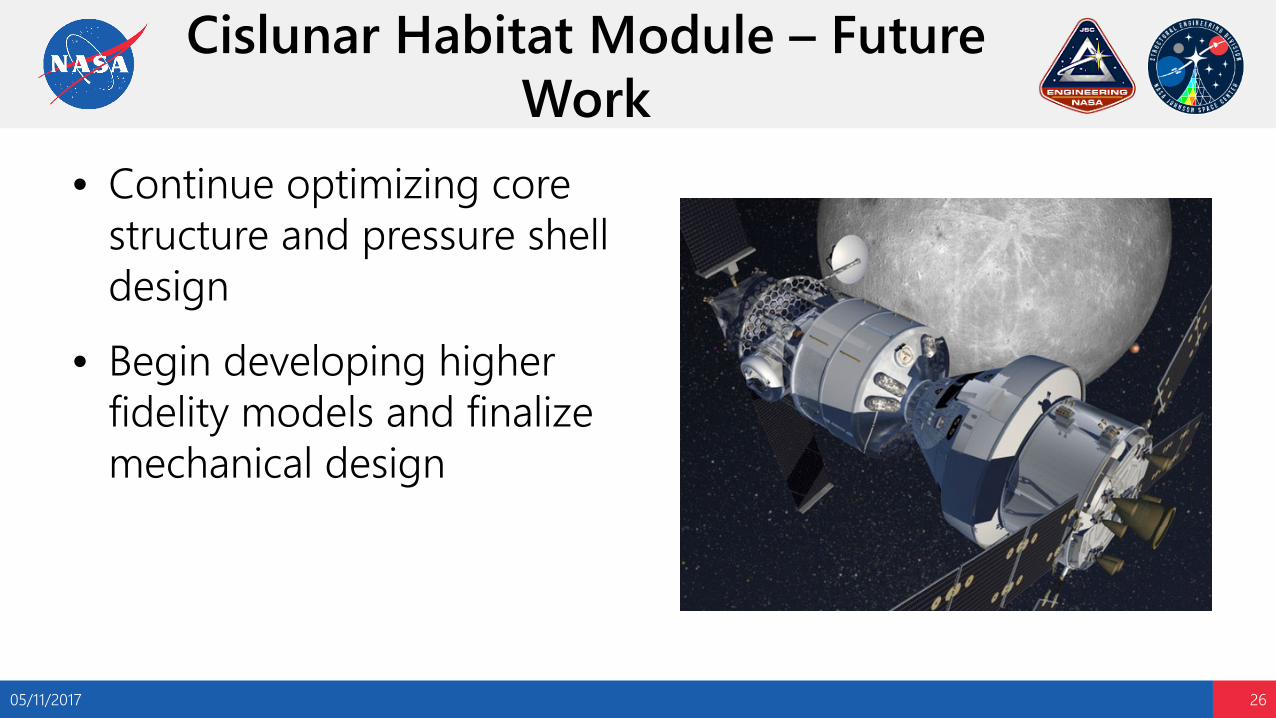
Cislunar Habitat Module – Future Work
• Continue optimizing core structure and pressure shell design
• Begin developing higher fidelity models and finalize mechanical design
05/11/2017 26

Content
• Background
• Lightweight External Inflatable Airlock (LEIA)
• Cislunar Habitat Module
• Artificial Gravity Study
• Additional Projects
• Conclusions
05/11/2017 27

Artificial Gravity Study – Overview
• Overall Objectives
– Artificial gravity (AG) forces should be directed through the feet
– The AG gradient should be minimized
– The duration of AG exposure should be around 1.5 hours/day
– The cross coupled angular accelerations caused by rotations of the head should be minimized
– AG at the feet shall be less than 2 g’s
05/11/2017 28
1g
ω
• Design Drivers
– Pressure shell diameter
– Volume limitations of the intended launch vehicle
– Mass limitations of the intended launch vehicle
– Isolation of the AG architecture from other parts of the vehicle
– Angular velocity required to achieve required accelerations
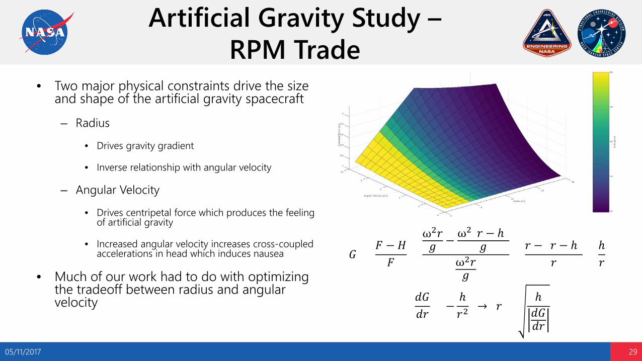
Artificial Gravity Study –RPM Trade
• Two major physical constraints drive the size and shape of the artificial gravity spacecraft
– Radius
• Drives gravity gradient
• Inverse relationship with angular velocity
– Angular Velocity
• Drives centripetal force which produces the feeling of artificial gravity
• Increased angular velocity increases cross-coupled accelerations in head which induces nausea
• Much of our work had to do with optimizing the tradeoff between radius and angular velocity
05/11/2017 29
𝐺𝐺 =𝐹𝐹 − 𝐻𝐻𝐹𝐹
=
ω2𝑟𝑟𝑔𝑔 − ω2(𝑟𝑟 − ℎ)
𝑔𝑔ω2𝑟𝑟𝑔𝑔
=𝑟𝑟 − (𝑟𝑟 − ℎ)
𝑟𝑟=ℎ𝑟𝑟
𝑑𝑑𝐺𝐺𝑑𝑑𝑟𝑟
= −ℎ𝑟𝑟2
→ 𝑟𝑟 =ℎ𝑑𝑑𝐺𝐺𝑑𝑑𝑟𝑟
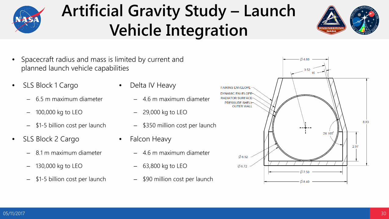
Artificial Gravity Study – Launch Vehicle Integration
05/11/2017 30
• SLS Block 1 Cargo
– 6.5 m maximum diameter
– 100,000 kg to LEO
– $1-5 billion cost per launch
• SLS Block 2 Cargo
– 8.1 m maximum diameter
– 130,000 kg to LEO
– $1-5 billion cost per launch
• Delta IV Heavy
– 4.6 m maximum diameter
– 29,000 kg to LEO
– $350 million cost per launch
• Falcon Heavy
– 4.6 m maximum diameter
– 63,800 kg to LEO
– $90 million cost per launch
• Spacecraft radius and mass is limited by current and planned launch vehicle capabilities

Artificial Gravity Study – Handcart Design Concept
• Expandable habitat with rigid outer wall for use as a track
• 7m stowed design• 13m deployed design• Determined the geometry
and mechanisms that would make this design feasible
05/11/2017 31

Artificial Gravity Study – Future Work
• Human Health Performance Directorate will have to conduct further research into the feasibility of artificial gravity at higher angular velocity
• Structures team has presented findings to SA & ES management
• We would like to see one of our concepts come to fruition and be used on either the ISS or the Deep Space Gateway
05/11/2017 32
Content
• Background
• Lightweight External Inflatable Airlock (LEIA)
• Cislunar Habitat Module
• Artificial Gravity Study
• Additional Projects
• Conclusions
05/11/2017 33

Additional Projects – Digital Image Correlation
05/11/2017 34
• Set up and wrote instructions for use of Digital Image Correlation software, Ncorr, for future use in the branch– Allows engineers to view strain heat
maps on real-world test articles
– Increases our understanding of the correlation between model and test data
• Ran the first test with the software• This will make Digital Image
Correlation more accessible at JSC
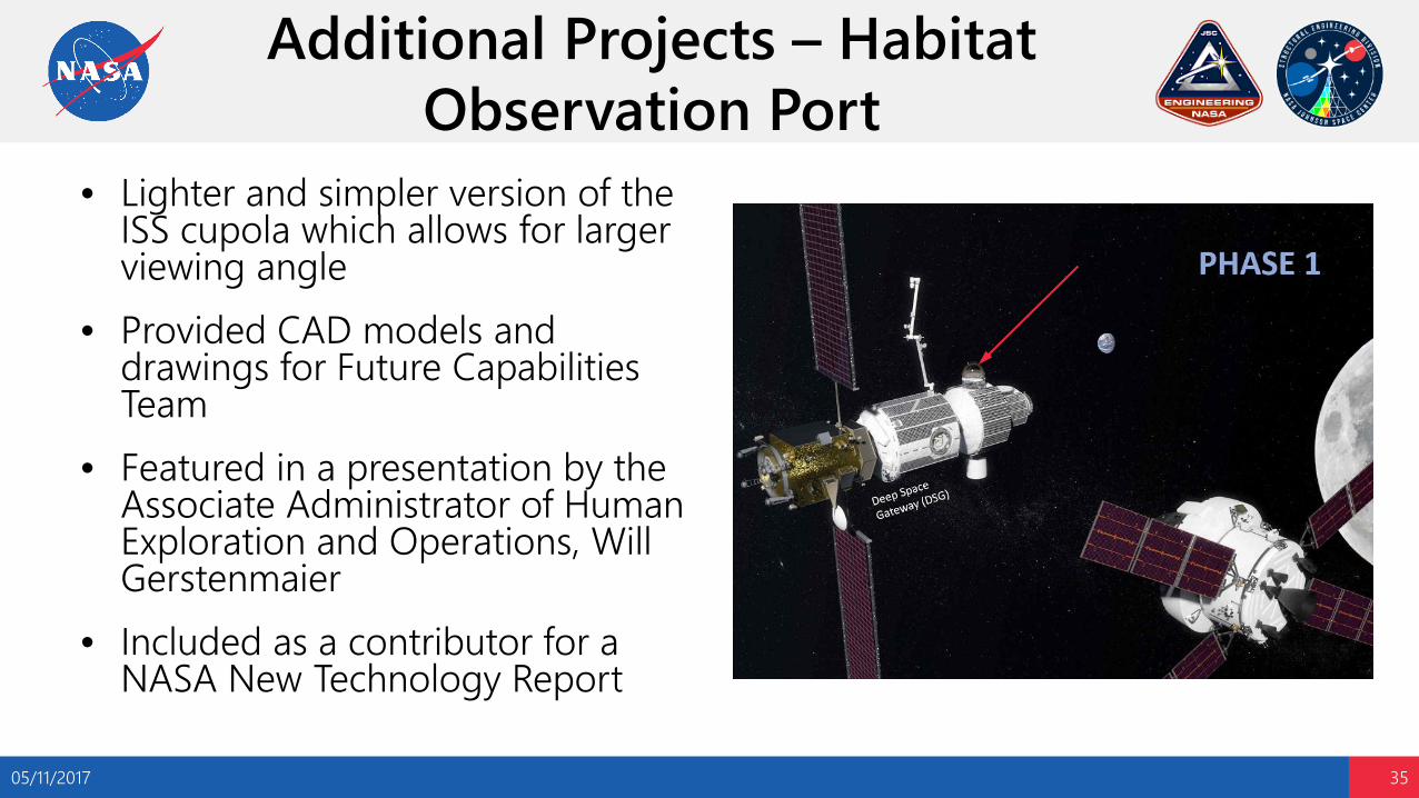
Additional Projects – Habitat Observation Port
05/11/2017 35
• Lighter and simpler version of the ISS cupola which allows for larger viewing angle
• Provided CAD models and drawings for Future Capabilities Team
• Featured in a presentation by the Associate Administrator of Human Exploration and Operations, Will Gerstenmaier
• Included as a contributor for a NASA New Technology Report
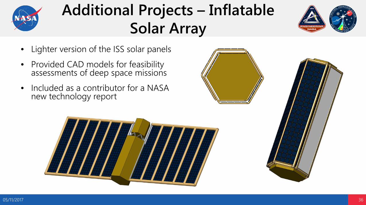
Additional Projects – Inflatable Solar Array
05/11/2017 36
• Lighter version of the ISS solar panels • Provided CAD models for feasibility
assessments of deep space missions• Included as a contributor for a NASA
new technology report

Additional Projects – Inflatable Radiator
05/11/2017 37
• Lighter version of the ISS radiators
• Provided CAD models for feasibility assessments of deep space missions
• Included as a contributor for a NASA New Technology Report

Additional Projects – John FigertSchool of Metallurgy
• Weekly lectures taught by John Figert
• Course Content– Raw Metal Forms and
Material Test Reports
– Mechanical Testing
– Metallic Alloy Selection
– Corrosion
– Heat Treatment of Steel Alloys
– Heat Treatment of Aluminum Alloys
05/11/2017 38
– Work-Hardening, Compressive Residual Stress, Thermal Stress Relief, and Distortion Issues
– JSC Central Manufacturing
– Coatings
– Welding
– Lubrication

Additional Projects – Around JSC
• Super Bowl• Astronaut food testing• JSC intern ultimate Frisbee team• Tour of Ellington Field by Victor Glover• Tour of moon rock facility• Lectures from several high-ranking
astronauts, flight directors, and JSC administrators
• Lecture on the causes and return to flight operations of the Challenger and Columbia disasters
05/11/2017 39

Content
• Background
• Lightweight External Inflatable Airlock (LEIA)
• Cislunar Habitat Module
• Artificial Gravity Study
• Other Projects
• Conclusions
05/11/2017 40
Conclusions – Lessons Learned
• Software Skills
– Creo Pro E
– Femap (first encounter)
– MATLAB
– NASTRAN (first encounter)
– NX (first encounter)
05/11/2017 41
• Non-Technical Skills
– Communication
– Prioritization and time management of multiple projects
• Engineering Skills
– Finite Element Modeling (first encounter)
– Stress analysis
– Structural optimization (first encounter)
– Spacecraft design (first encounter)

Conclusions – Acknowledgements
• Courtney Barringer
• Melissa Corning
• John Figert
• Greg Galbreath
• Mykale-Jamal Holland
• Doug Litteken
• Kornel Nagy05/11/2017 42
• Khadijah Shariff
• James Smith
• Kayla Smith
• Pamela Vasseur
• John Zipay
• Room 219
• Everyone in ES
Thank you all for making this a rewarding semester!

Conclusions – Future Plans
• Summer 2017– Propulsion Engineering intern at SpaceX
• Fall 2017 – Spring 2018– Finish undergraduate aerospace
engineering degree at Georgia Tech
– Determine the best course of action for my early career
• Summer 2018 – Unknown– Begin career
– Begin grad school
05/11/2017 43

Questions?
05/11/2017 44


