

johnb
DFDs and Design
John Bell
The DeMarco notation

johnb
Uses of DFDs
o used to represent the processing which occurs within systems
o most systems are too complex to be represented by just 1 DFD - so the system is partitioned into a hierarchy of manageable components, each consisting of related processes

johnb
Uses of DFDs
o a DFD can be viewed as either a physical or a logical DFD depending on the extent to which it does or does not model a technology-specific implementation
o desirable to produce logical DFDs which represent what the processing is required to accomplish, rather than physical DFDs which represent how the processing requirements are met

johnb
Uses of DFDs
o Physical DFDs may be used to assist with understanding of existing processing and as an aid to deriving the logical DFD
o DFDs:» do not include any procedural, control or
timing aspects of processing. Initialisation, termination or control are not modelled
johnb
DFDs
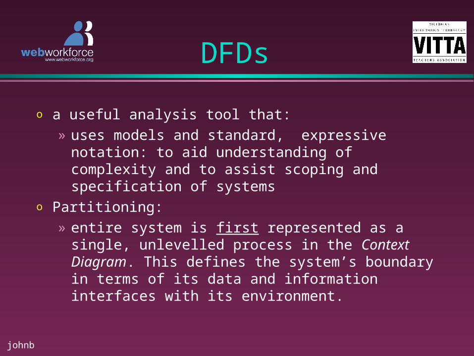
o a useful analysis tool that: » uses models and standard, expressive notation: to
aid understanding of complexity and to assist scoping and specification of systems
o Partitioning:» entire system is first represented as a single,
unlevelled process in the Context Diagram. This defines the system’s boundary in terms of its data and information interfaces with its environment.
johnb
DFDs
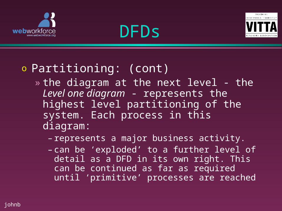
o Partitioning: (cont)» the diagram at the next level - the Level
one diagram - represents the highest level partitioning of the system. Each process in this diagram:
– represents a major business activity. – can be ‘exploded’ to a further level of detail as a
DFD in its own right. This can be continued as far as required until ‘primitive’ processes are reached

johnb
4 DFD Objects
o 1. External Entity» represents any person, thing or system
external to the processing in the diagram and which either supplies data to the processing (a ‘Source’) or receives data output from the processing (a ‘Sink’)
Customer

johnb
4 DFD Objects
o 2. Data Flow» represents a ‘packet‘ of data moving
between objects
o 3. Data Store» represents data either temporarily or
permanently at rest
cash sale details Transactions
data flow data store
johnb
4 DFD Objects
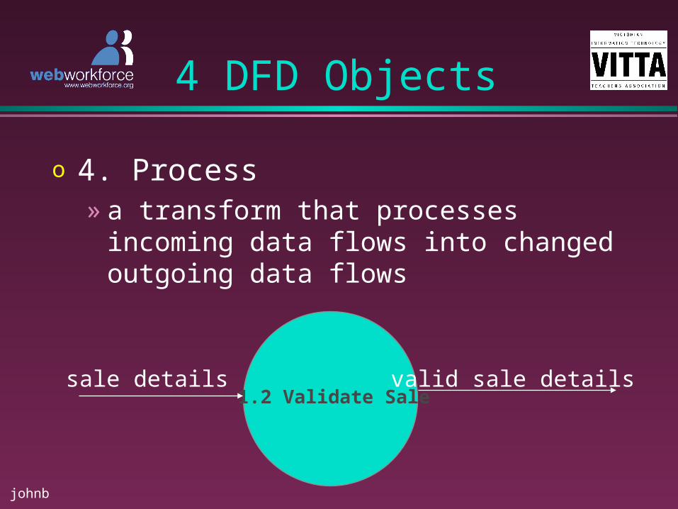
o 4. Process» a transform that processes incoming data
flows into changed outgoing data flows
1.2 Validate Salesale details valid sale details

johnb
DFD Objects
ProcessesProcesses
• each process should have a unique number and a name that describes clearly what the process does
• should use a verb and a noun phrase (eg. compute price, validate customer data, accept supplier delivery) and avoid vague names (eg. process data)
2.1
compute price
process data

johnb
DFD Objects
ProcessesProcesses
• a process MUST have at least 1 data flow entering in and at least 1 data flow flowing out of it and there must be a change in the contents of data flows

johnb
DFD Objects
Data FlowsData Flows
• represent data ‘packets’ moving through the system
• the name should describe the contents of the data packet - use a noun phrase - and imply the contents of the the data flow as clearly as possible (eg “customer payment” rather than just “payment”)
2.1
validate customer order
customer order
invalid customerorder
valid customer order

johnb
DFD Objects
Data FlowsData Flows
• data flows can diverge when duplicate packets of data are sent to different parts of the system
2.1
2.2
2.3
validate sales orders
generateinvoices sales
generate shipping slips
valid salesorder
invoice
shipping slip
johnb
DFD Objects
Data FlowsData Flows
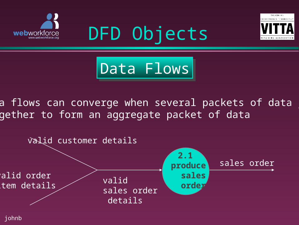
• data flows can converge when several packets of data join together to form an aggregate packet of data
2.1produce sales order
valid customer details
valid order item details
valid sales order details
sales order

johnb
DFD Objects
Data FlowsData Flows
• data flows are permitted
• between 2 processes• from a data store to a process• from a process to a data store• from a source to a process• from a process to a sink

johnb
DFD Objects
Data FlowsData Flows• omit any processing required to handle “trivial rejects” - ie. rejects where no work needs to be undone
• show the possibility of trivial rejects by using a data flow labelled “reject”. It is allowable for such flows to have no destination indicated
2.1
produce sales order
2.1
produce sales order
3.2 validateapplications
3.1 registerapplications
3.3
assess applications
application
registeredapplication
validapplication
approvedapplication
reject
johnb
DFD Objects
Data StoresData Stores
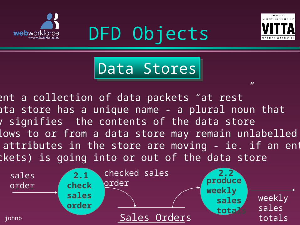
• represent a collection of data packets “at rest”• each data store has a unique name - a plural noun that clearly signifies the contents of the data store• data flows to or from a data store may remain unlabelled if all attributes in the store are moving - ie. if an entire packet (or packets) is going into or out of the data store
2.2produceweekly sales totals
2.1checksalesorder
Sales Orders
salesorder
checked salesorder
weekly salestotals

johnb
DFD Objects
Data StoresData Stores
• each data store may correspond to 1 or more entities in the logical data model
Sales Orders
Sales Order
Item

johnb
DFD Objects
External AgentsExternal Agents
• represent external objects with which the system communicates and which are outside the scope of the system
eg. outside organisation or individualgovernment agencyanother departmentanother system
• data flows connecting the external agents to processes within the system represent the interface between the system and its environment

johnb
Drawing DFDs
Context DiagramsContext Diagrams
• the highest level DFD that shows the interaction with the system and its environment (data flows) and defines the system boundary
Customer
TaxOffice
Supplier Orderinventory system
sales order
invoice
payment
sales tax details
purchase order
delivery
invoice
johnb
Drawing DFDs
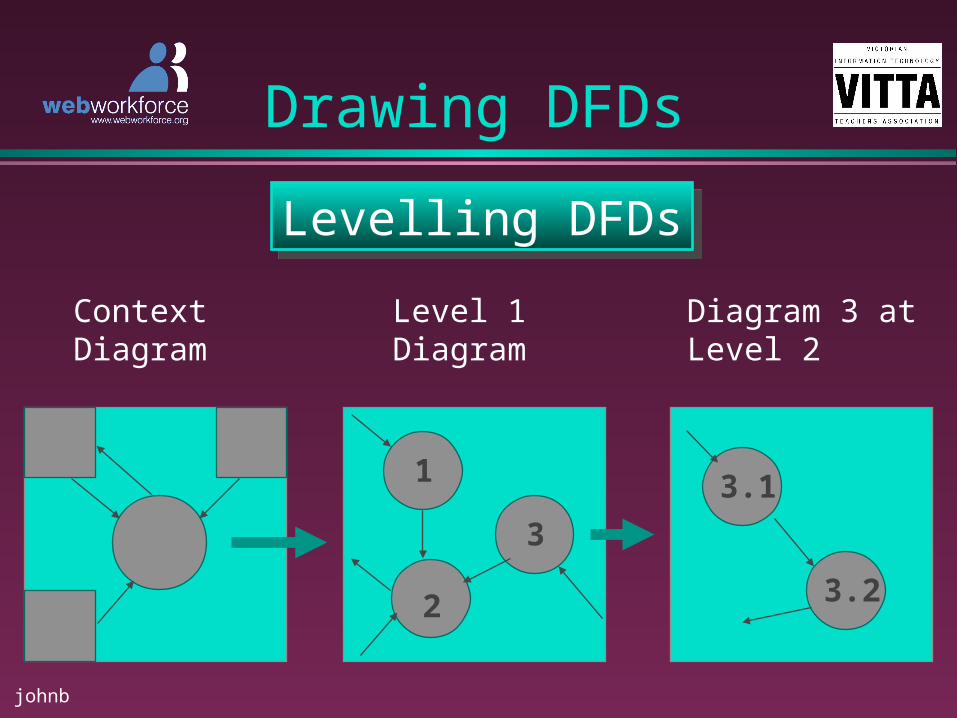
Levelling DFDsLevelling DFDs
1
3
2
3.1
3.2
ContextDiagram
Level 1Diagram
Diagram 3 atLevel 2

johnb
Drawing DFDs
Levelling rulesLevelling rules
• the data that flows into and out of a parent process must match the data that flows into and out of the related child diagram• diagrams should have approximately no more than 7 processes• levelling should continue until bottom level or primitive processes are reached• not all parts of the system need to be decomposed to the same level
johnb
Drawing DFDs
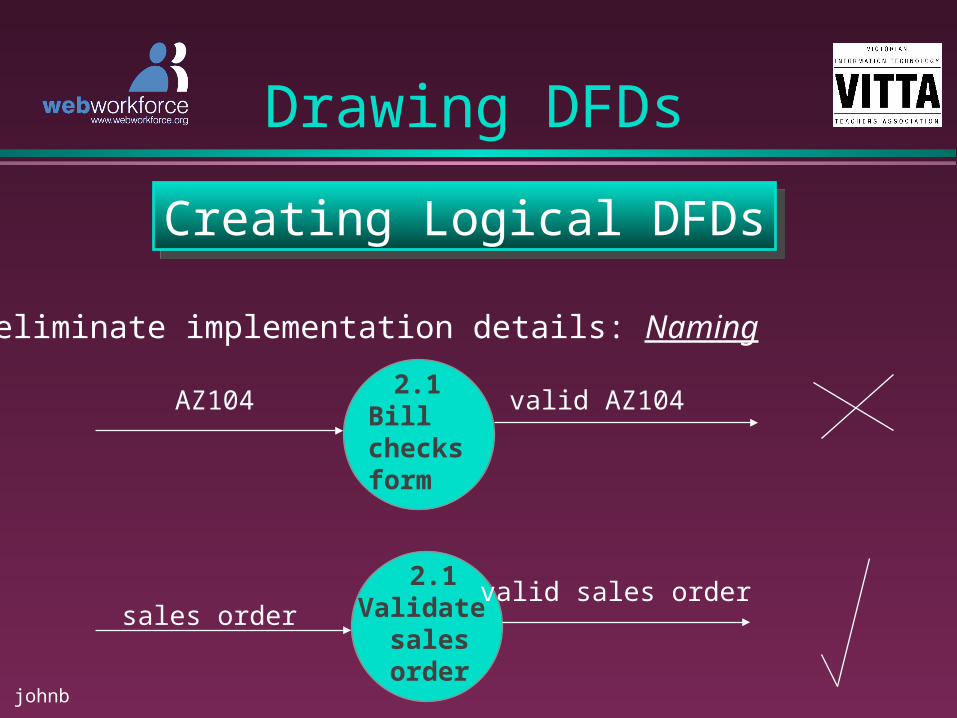
Creating Logical DFDsCreating Logical DFDs
• eliminate implementation details: Naming
2.1Billchecks form
2.1Validate sales order
AZ104
sales ordervalid sales order
valid AZ104

johnb
Drawing DFDs
Physical DFDsPhysical DFDs• example of a physical DFD for an order processing system – NB …. DFDs should NOT be drawn this way
2.1
Receptionclerk
x4 order form checked x4 form2.2
Sort intoareas
2.3send toproductionsection
sorted x4forms.
2.4
productionsection
despatchedorders
A66-productionrequest form

johnb
Drawing DFDs
Creating Logical DFDsCreating Logical DFDs
• logical DFD of the same processing
2.1checkcustomer order
customer orderchecked customer order
2.2Checkproductionfeasibility
2.3
commitresources
accepted order
order
resources schedule
orderdetails
resources used


