

NASASPACEVEHICLEDESIGNCRITERIA
(CHEMICALPROPULSION)
NASA SP-8109
LIQUID ROCKET ENGINE
CENTRIFUGALFLOWTURBOPUMPS
J
,.L
DECEMBER1973
NATIONAL AERONAUTICS AND SPACE ADMINISTRATION

FOREWORD
NASA experience has indicated a need for uniform criteria for the design of space vehicles.
Accordingly, criteria are being developed in the following areas of technology:
Environment
Structures
Guidance and Control
Chemical Propulsion
Individual components of this work will be issued as separate monographs as soon as they
are completed. This document, part of the series on Chemical Propulsion, is one such
monograph. A list of all monographs issued prior to this one can be found on the final pagesof this document.
These monographs are to be regarded as guides to design and not as NASA requirements,
except as may be specified in formal project specifications. It is expected, however, thatthese documents, revised as experience may indicate to be desirable, eventually will provide
uniform design practices for NASA space vehicles.
This monograph, "Liquid Rocket Engine Centrifugal Flow Turbopumps", was preparedunder the direction of Howard W. Douglass, Chief, Design Criteria Office, Lewis Research
Center; project management was by Harold Schmidt. The monograph was written by R. B.
Furst of Rocketdyne Division, Rockwell International Corporation, and was edited by
Russell B. Keller, Jr. of Lewis. Significant contributions to the text were made by H.
Campen and F. Viteri of Aerojet Liquid Rocket Company. To assure technical accuracy ofthis document, scientists and engineers throughout the technical community participated in
interviews, consultations, and critical review of the text. In particular, Mario Messina of Bell
Aerospace Company; Glen M. Wood of United Aircraft Corporation; and C. H. Hauser andDean D. Scheer of the Lewis Research Center individually and collectively reviewed the text
in detail.
Comments concerning the technical content of this monograph will be welcomed by theNational Aeronautics and Space Administration, Lewis Research Center (Design Criteria
Office), Cleveland, OH 44135.
December 1973

For sale by the Nationai _'echnical Information ServiceSpringfield, Virginia 22151Price- $4.50
GUIDE TO THE USE OF THIS MONOGRAPH
The purpose of this monograph is to organize and present, for effective use in design, thesignificant experience and knowledge accumulated in development and operational
programs to date. It reviews and assesses current design practices, and from them establishes
firm guidance for achieving greater consistency in design, increased reliability in the end
product, and greater efficiency in the design effort. The monograph is organized into twomajor sections that are preceded by a brief introduction and complemented by a set of
references.
The State of the Art, section 2, reviews and discusses the total design problem, and
identifies which design elements are involved in successful design. It describes succinctly the
current tecnnology pertaining to these elements. When detailed information is required, thebest available references are cited. This section serves as a survey of the subject that provides
background material and prepares a proper technological base for the Design Criteria and
Recommended Practices.
The Design Criter&, shown in italics in section 3, state clearly and briefly what rule, guide,
limitation, or standard must be imposed on each essential design element to assuresuccessful design. The Design Criteria can serve effectively as a checklist of rules for the
project manager to use in guiding a design or in assessing its adequacy.
The Recommended Practices, also in section 3, state how to satisfy each of the criteria.
Whenever possible, the best procedure is described; when this cannot be done concisely,
appropriate references are provided. The Recommended Practices, in conjunction with theDesign Criteria, provide positive guidance to the practicing designer on how to achieve
successful design.
Both sections have been organized into decimally numbered subsections so that the subjects
within similarly numbered subsections correspond from section to section. The format for
the Contents displays this continuity of subject in such a way that a particular aspect of
design can be followed through both sections as a discrete subject.
The design criteria monograph is not intended to be a design handbook, a set of
specifications, or a design manual. It is a summary and a systematic ordering of the large andloosely organized body of existing successful design techniques and practices. Its value andits merit should be judged on how effectively it makes that material available to and useful
to the designer.
iii

CONTENTS
1.
2.
3.
INTRODUCTION .....................
STATE OF THE ART ...................
DESIGN CRITERIA and Recommended Practices .........
APPENDIX A Glossary ............................
APPENDIX B Conversion of U. S. Customary Units to SI Units .............
REFERENCES ..............................
NASA Space Vehicle Design Criteria Monographs Issued to Date ...........
Page
1
3
61
87
95
97
103
SUBJECT STATE OF THE ART DESIGN CRITERIA
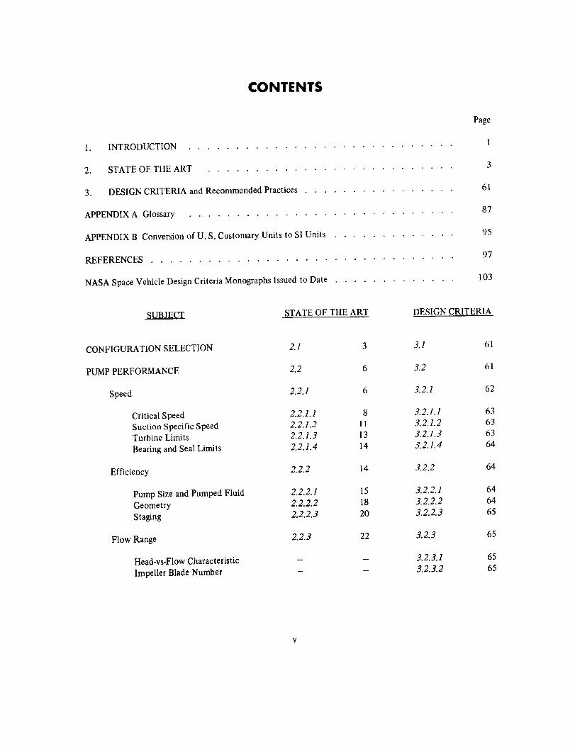
CONFIGURATION SELECTION 2. I 3 3.1 61
PUMP PERFORMANCE 2.2 6 3.2 61
Speed 2.2.1 6 3.2.1 62
Critical Speed 2.2.1.1 8 3.2.1.1 63Suction Specific Speed 2.2.1.2 11 3.2.1.2 63Turbine Limits 2.2.1.3 13 3.2.1.3 63
Bearing and Seal Limits 2.2.1.4 14 3.2.1.4 64
Efficiency 2.2.2 14 3.2.2 64
Pump Size and Pumped Fluid 2.2.2.1 15 3.2.2.1 64
Geometry 2.2.2.2 18 3.2.2.2 64
Staging 2.2.2.3 20 3.2.2.3 65
Flow Range 2.2.3 22 3.2.3 65
Head-vs-Flow Characteristic - - 3.2.3.1 65- 3.2.3.2 65
Impeller Blade Number
SUBJECT STATE OF THE ART DESIGN CRITERIA
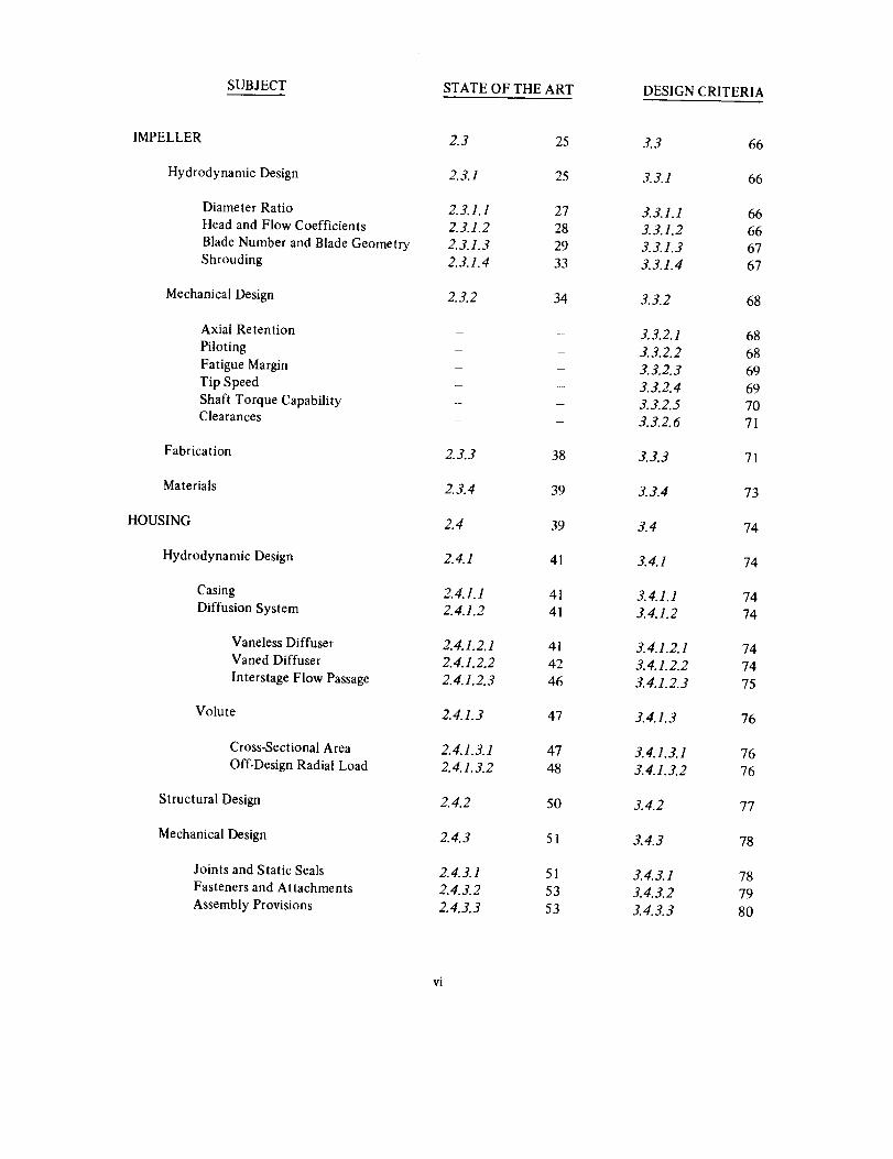
IMPELLER 2.3 25 3.3 66
Hydrodynamic Design 2.3.1 25 3.3.1 66
Diameter Ratio 2. 3.1.1 27 3. 3.1.1 66
Head and Flow Coefficients 2.3.1.2 28 3.3.1.2 66
Blade Number and Blade Geometry 2.3.1.3 29 3.3.1.3 67
Shrouding 2.3.1.4 33 3.3.1.4 67
Mechanical Design 2.3.2 34 3.3.2 68
Axial Retention - 3. 3.2. I 68Piloting - 3.3.2.2 68Fatigue Margin - 3.3.2.3 69Tip Speed - 3.3.2.4 69Shaft Torque Capability - - 3.3.2.5 70Clearances - 3.3.2.6 71
Fabrication 2. 3.3 38 3. 3.3 71
Materials 2.3.4 39 3.3.4 73
HOUSING 2.4 39 3.4 74
Hydrodynamic Design 2.4.1 41 3.4.1 74
Casing 2.4.1.1 41 3. 4.1.1 74
Diffusion System 2.4.1.2 41 3.4.1.2 74
Vaneless Diffuser 2.4.1.2.1 41 3.4.1.2.1 74
Vaned Diffuser 2.4.1.2.2 42 3.4.1.2.2 74
Interstage Flow Passage 2.4.1.2.3 46 3.4.1.2.3 75
Volute 2.4.1.3 47 3.4.1.3 76
Cross-Sectional Area 2.4.1.3.1 47 3.4.1.3.1 76
Off-Design Radial Load 2.4.1.3.2 48 3.4.1.3.2 76
Structural Design 2.4.2 50 3.4.2 77
Mechanical Design 2.4.3 51 3.4.3 78
Joints and Static Seals 2.4.3.1 51 3.4.3.1 78
Fasteners and Attachments 2.4.3.2 53 3.4.3.2 79
Assembly Provisions 2.4.3.3 53 3.4.3.3 80
vi
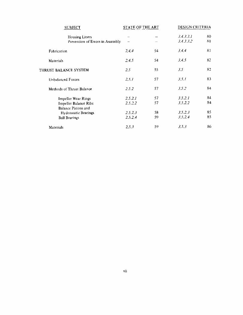
SUBJECT STATE OF THE ART DESIGN CRITERIA
Housing LinersPrevention of Errors in Assembly
Fabrication
Materials
THRUST BALANCE SYSTEM
Unbalanced Forces
Methods of Thrust Balance
Impeller Wear Rings
Impeller Balance RibsBalance Pistons and
Hydrostatic Bearings
Ball Bearings
Materials
- - 3.4.3.3.1 80
- - 3.4.3.3.2 81
2.4.4 54 3.4.4 81
2.4.5 54 3.4.5 82
2.5 55 3.5 82
2.5.1 57 3.5.1 83
2.5.2 57 3.5.2 84
2.5.2.1 57 3.5.2.1 84
2.5.2.2 57 3.5.2.2 84
2.5.2.3 58 3.5.2.3 85
2.5.2.4 59 3.5.2.4 85
2.5.3 59 3.5.3 86
vii
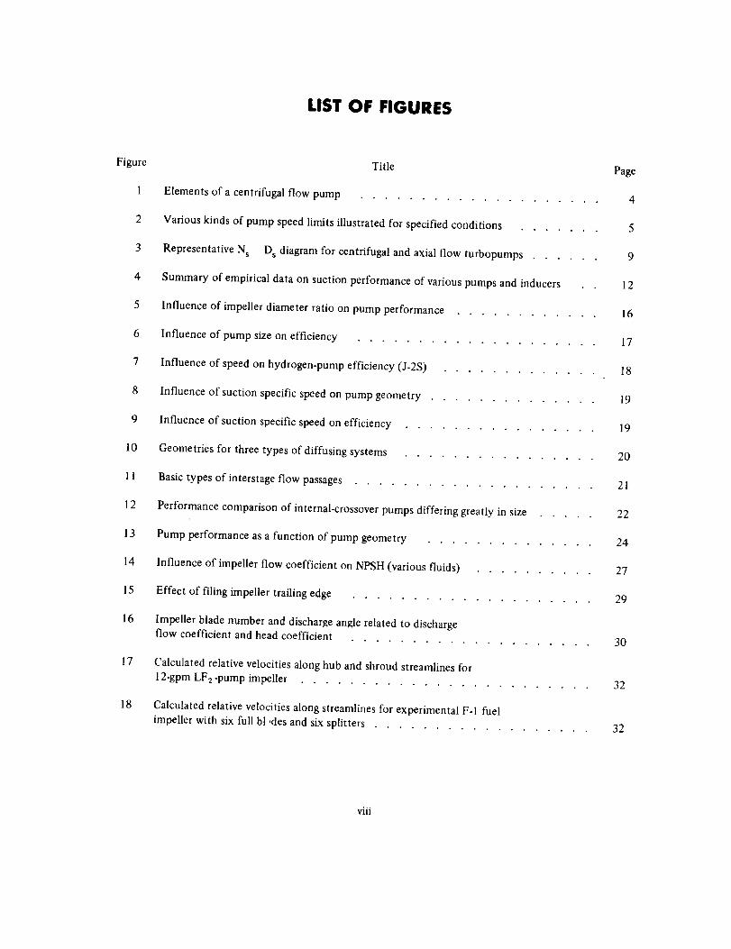
LIST OF FIGURES
Figure
1
2
3
4
5
6
7
8
9
10
11
12
13
14
15
16
17
18
Title Page
Elements of a centrifugal flow pump .................... 4
Various kinds of pump speed limits illustrated for specified conditions ....... 5
Representative Ns - D s diagram for centrifugal and axial flow turbopumps ...... 9
Summary of empirical data on suction performance of various pumps and inducers 12
Influence of impeller diameter ratio on pump performance ............ 16
Influence of pump size on efficiency .................... 17
Influence of speed on hydrogen-pump efficiency (J-2S) ............. 18
Influence of suction specific speed on pump geometry .............. 19
Influence of suction specific speed on efficiency ................ 19
Geometries for three types of diffusing systems ................ 20
Basic types of interstage flow passages .................... 21
Performance comparison of internal-crossover pumps differing greatly in size ..... 22
Pump performance as a function of pump geometry .............. 24
Influence of impeller flow coefficient on NPSH (various fluids) .......... 27
Effect of filing impeller trailing edge .................... 29
Impeller blade number and discharge angle related to dischargeflow coefficient and head coefficient
.................... 30
Calculated relative velocities along hub and shroud streamlines for
12-gpm LF2-pump impeller ........................ 32
Calculated relative velocities along streamlines for experimental F-1 fuel
impeller with six full bt ,des and six splitters .................. 32
viii
Figure
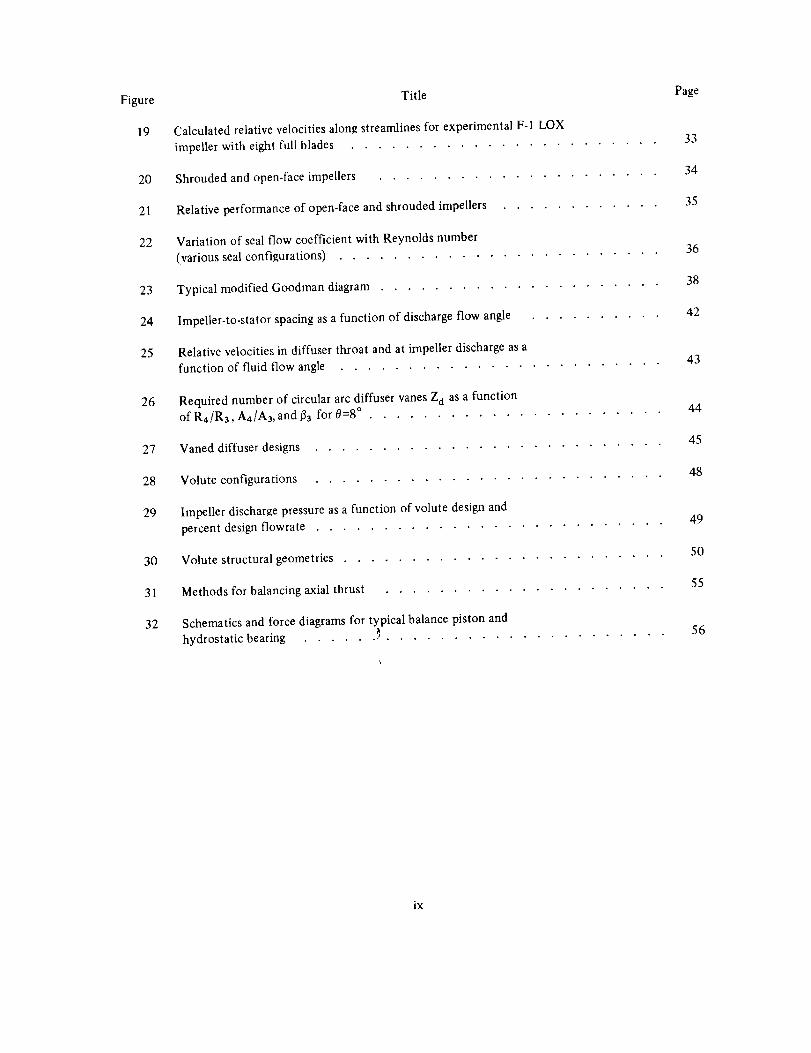
19
PageTitle
Calculatedrelativevelocitiesalon!_streamlinesforexperimentalF-1LOX33
impellerwitheightfullblades .......................
20 Shroudedandopen-faceimpellers ..................... 34
21 Relativeperformanceofopen-faceandshroudedimpellers............ 35
22 VariationofsealflowcoefficientwithReynoldsnumber 36(varioussealconfigurations)........................
3823 TypicalmodifiedGoodmandiagram.....................
4224 Impeller-to-statorspacingasafunctionof dischargeflowangle .........
25 Relativevelocitiesindiffuserthroatandatimpellerdischargeasa 43functionoffluidflowangle ........................
26 RequirednumberofcirculararcdiffuservanesZ o as a function 44of R4/R3, A4/A3, and/33 for 0=8 ° . .....................
4527 Vaned diffuser designs ..........................
4828 Volute configurations ..........................
29 Impeller discharge pressure as a function of volute design and49
percent design flowrate ........................
5O30 Volute structural geometries ........................
31 Methods for balancing axial thrust ..................... 55
32 Schematics and force diagrams for typical balance piston and
hydrostatic bearing ...... _ ..................... 56
ix
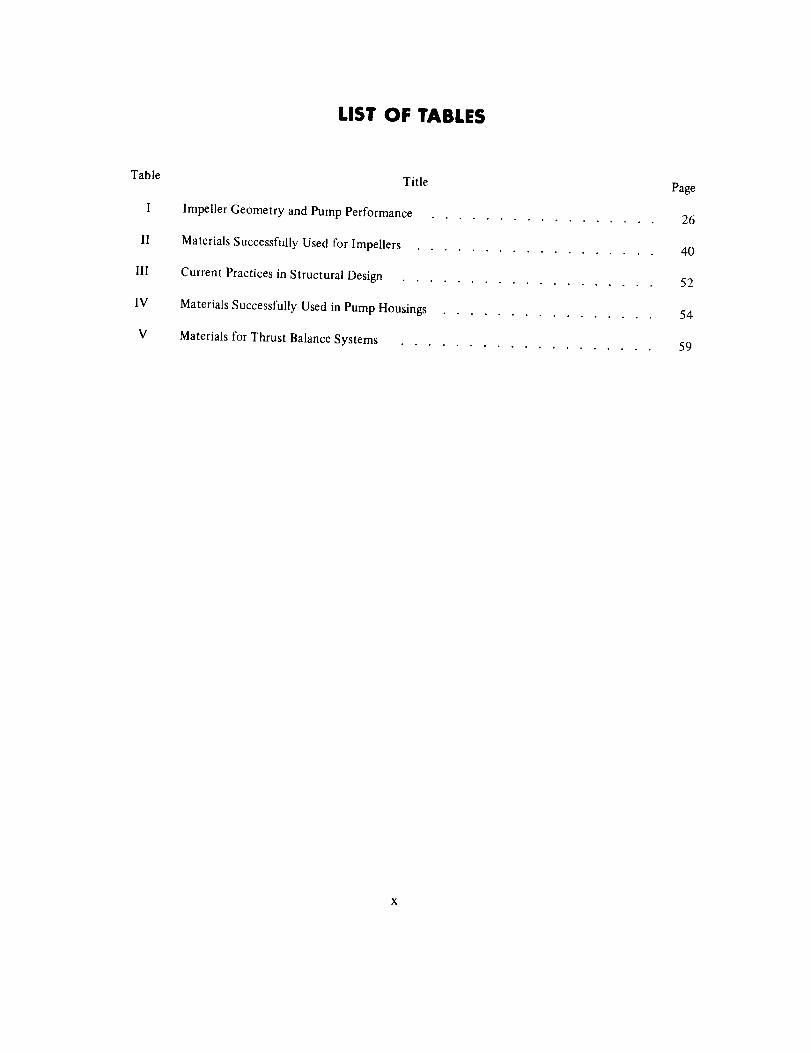
LIST OF TABLES
Table
I
II
Ill
IV
V
Title Page
Impeller Geometry and Pump Performance 26
Materials Successfully Used for Impellers 40
Current Practices in Structural Design ................... 52
Materials Successfully Used in Pump Housings ................ 54
Materials for Thrust Balance Systems ................... 59
LIQUID ROCKET ENGINE
CENTRIFUGAL FLOW TURBOPUMPS
1. INTRODUCTION
The acceptance and highly successful application of centrifugal pumps in chemical as well asnuclear rocket engines result from the simplicity, reliability, light weight, wide operating
range, minimal development time, and relatively low costs of these pumps. Usually, other
types of pumps become competitive with the centrifugal design only when multistaging is
necessary or maximum efficiency of operation is the paramount consideration.
In rocket engine applications, the requirements for light weight and low inlet pressures have
resulted in many pump problems. These problems have included impeller rubbing that
resulted in oxidizer-pump explosions; bearing failures caused by high axial and radial thrust;excessive cavitation damage; inadequate suction performance; undesirable oscillations in
suction and discharge pressure; impeller blade failures; housing ruptures; stress-corrosion
cracking; loss of design fits caused by centrifugal or thermal loads; static-seal leakage; and
inadequate retention of the components. Additionally, problems have been encounteredwherein the structural and dynamic characteristics of the vehicle were involved with those
of the pumping system (i.e., POGO effect upon Titan |I and Saturn t ). The solutions to such
problems become highly complex.
A particular problem with liquid-hydrogen pumps is the small tip width required for the
impeller blade; present designs are rpm-limited and therefore operate normally at loweroverall specific speeds than dense-liquid pumps because of the high head rise required. The
requirement for small tip width results in fabrication difficulties and lower efficiencies.
Improved designs for liquid-hydrogen pumps will require the extension of the currenttechnology for bearings and seals and axial thrust balance systems; increases in critical speed
by the use of bearings outboard of the turbine; increases in turbine speed and flow
capability; the use of low-speed preinducers to satisfy required inlet pressure limits; and
efficient interstage diffusers for multistage pumps.
Some of the pump problems indicated above resulted partially from insufficient backgroundinformation for application to design analyses. The early axial and radial thrust problems
1 Symbols, materials, and pumps, engines, and vehicles are identified in Appendix A.
associated with the turbopumps for the Titan I, Atlas, and Thor are attributable to this
insufficiency. Also, cracking of cast impeller blades resulted from inadequate information
on aluminum casting techniques for production of greatly differing cross-sectionthicknesses; stress corrosion of aluminum impellers and inducers arose from insufficient
background in the influence of heat treatment on different alloys; and limited knowledge ofinducer and impeller radial loads resulted in forces sufficient to cause pump inducer andimpeller rubbing that led to catastrophic explosions. Some problems occurred because of
poor design. For example, the design of cast or drilled bearing-coolant passages that could
not be adequately cleaned or inspected resulted in clogging followed by bearing heating;
overheated bearings operating in an oxidizer caused explosions or resulted in rubbing ofother components that were damaged or that caused explosions.
This monograph presents the useful knowledge derived from these experiences so that
similar problems may be avoided in future designs. The material within the monograph isorganized along the lines of the pump design sequence. The arrangement and treatment of
the subject matter emphasizes that the basic objective of the design effort is to achieve
required pump performance within the constraints imposed by the engine/turbopump
system. The design must provide this performance while maintaining structural integrityunder all operating conditions. Such a design depends on simultaneous solutions of
hydrodynamic and mechanical problems, as developed in the monograph.
2
2. STATE OF THE ART
Centrifugal pumps have generated up to 100 000 feet I of head in a single stage; they havebeen staged to generate even higher heads. Pumps for dense liquids (specific gravity >_1)
have been developed with flowrates ranging from 12 gpm at 75 000 rpm to 30 000 gpm at
5800 rpm; liquid-hydrogen pumps have delivered over the range of 800 gpm to 13 000 gpm
at 46 000 rpm. The centrifugal pump is capable of operating over a wide range of flowratewithout stall or surge. The centrifugal pump with shrouded impellers may operate with
relatively large clearances between rotating and stationary parts; this characteristic is
particularly advantageous when the pumped fluid is a highly reactive oxidizer. Once the
basic pump requirements have been satisfied, the success of the centrifugal flow pump in arocket engine system depends upon the designer's ability to recognize the cause and
suppress the effect of the undesirable, often destructive, dynamic behavior associated with
cavitation, start transients, and engine-feed-system oscillations.
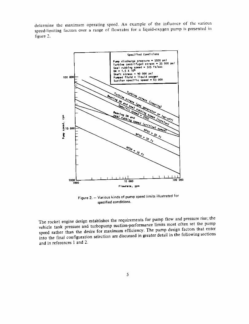
Figure 1 illustrates the elements of a typical centrifugal flow pump and provides a basis for
the discussions of pump design that follow.
2.1 CONFIGURATION SELECTION
The selection of a pump configuration is influenced by operational, hydrodynamic, andmechanical considerations that include inlet pressure, maximum impeller tip speed, limiting
pressure per stage, engine-system compatibility, flow-range requirements, envelope size,pumped fluid, and weight. Many of these factors are interrelated, and some of them are
established by the mission or vehicle requirements.
Past experience supports the need for considering limitations on rotating speed, even though
the rotating speed should be as great as possible in order to minimize turbopump weight.
Maximum pump efficiency, however, may be attained at a speed lower than maximum. Theinfluence of efficiency must then be traded off to minimize equivalent weight (i.e., the
increase in vehicle weight for a given loss in efficiency). Shaft critical speed is often a
speed-limiting design factor. Critical speed is closely related to the location and size of thebearings and seals, and is influenced by the bearing spring rate. Bearing size must be
sufficient to carry required axial and radial loads, and the bearing speed capability decreases
as its capacity and size is increased. A relatively large stiff shaft is required to attain high
critical speeds; however, the size of the shaft is limited by the maximum rubbing velocity ofthe shaft seals. The vehicle design considerations set the minimum pump inlet pressures, andthe attainable suction specific speed(s) capability of the pump often limits the attainable
speed. For high-speed, high-power liquid-hydrogen pumps, the turbine stress limits may
I Factors for converting U.S. customary units to the International System of Units (SI units) are given in Appendix B.

Pump casingVolute passage(to discharge)
Front wear ringwear rlng
(optional for hydraulicbalancing of axialthrust In place ofbalance rlbs)
Balance ribs
Fluidflow
'Drive S_/_
Inlet flangeL.
Inducer
Impellel
t bearings
t seals
Diffuser vanes
Figure 1. - Elements of a centrifugal flow pump.
4
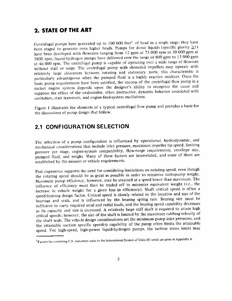
determine the maximum operating speed. An example of the influence of the various
speed-limiting factors over a range of flowrates for a liquid-oxygen pump is presented in
figure 2.
100 000 l
Speclfled Conditions
Pump discharge pressure - 5500 psiTurbine centrifugal stress - 35 000 psi
Seal rubbing speed - 325 ft/sec
Dfl - 1.5 X 10⁶
Shift stress " 40 000 psi
Pumped fluid - llquld oxygenSuction specific speed - 63 000
LL
_0
_10 00_
IOOCI000
10 000
Flowrate, gpm
I00 000
Figure 2. - Various kinds of pump speed limits illustrated for
specified conditions.
The rocket engine design establishes the requirements for pump flow and pressure rise; the
vehicle tank pressure and turbopump suction-performance limits most often set the pump
speed rather than the desire for maximum efficiency. The pump design factors that enterinto the final configuration selection are discussed in greater detail in the following sections
and in references 1 and 2.
2.2 PUMP PERFORMANCE
The pump design is based primarily on the specified engine operating conditions (i.e.,
flowrate, headrise, and inlet pressure) and on other requirements such as throttling, system
stability, turbine power margin, and the allowable pump development time. The best
compromise of all requirements may be achieved at an efficiency point higher or lower than
that at the nominal operating flowrate. The best-efficiency point relative to the operatingpoint is established along with the selection of the shape of the headrise/capacity curve. Inorder to ensure that all information that influences pump performance is considered in
design, a design specification is prepared to consolidate the available data and to point outthe information that must be supplied by future analyses or tests.
The complexity of a pump increases with the number of stages required; therefore, the
maximum pressure rise per stage is a significant design parameter in evaluating
configurations for a given application. The impeller stress limits at high impeller tip speeds
restrict the maximum headrise per stage to approximately 100 000 ft. A two-stage pumpmay generate up to 200 000 ft. of head, which is approximately 7000 psi when the fluid is
liquid hydrogen. Because of its low density, liquid hydrogen is the only propellant requiringvery high headrise and impeller tip speed.
Rocket engine pump efficiencies are lower than those of commercial pumps with
comparable specific speeds (ref. 3), as discussed in section 2.2.2. Efficiency is dependent onsize rather than on flowrate; therefore, the rocket engine pump flow usually is corrected to
a speed corresponding to commercial pump practice before efficiencies at a given specificspeed are compared.
2.2.1 Speed
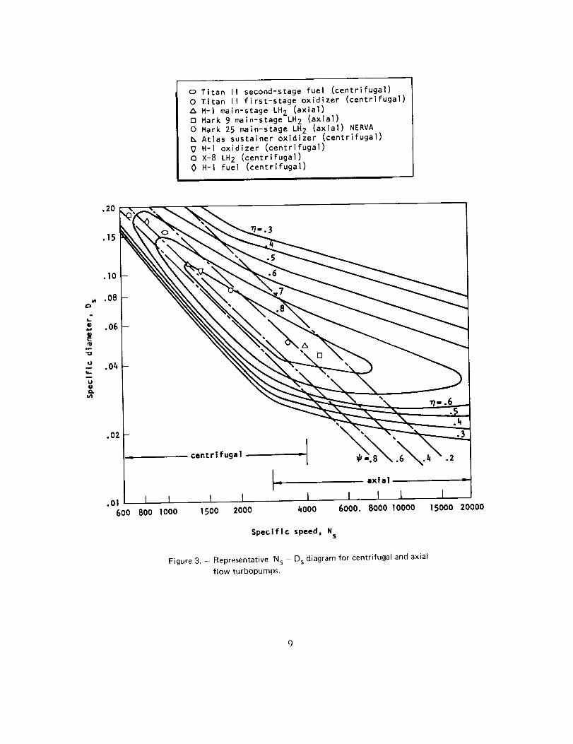
The specific speed NS and specific diameter D s are useful parameters for classifying pumptypes because they indicate the stage characteristics and identify specific areas where the
various pump configurations are best suited for the application. In addition, these
parameters provide preliminary estimates of pump efficiency and pump size (diameter). Thesignificance of N s and Ds in pump design is evident in the expressions for the twoparameters'
NQ v_N_ -
(1)
Dt2H '/.D s -
QI/2 (2)
6
where
N = rotationalspeed
Q = volumetricflowrate
H = headrise
Dt2 = dischargetip diameter
Current flight-provencentrifugalflow pumpsrangefrom 450 to 2100 in specificspeed;somedevelopmentpumps(e.g.,theMark 14for theAtlasvehicle)havereached3000.
Two other parametersof significancein thebasicpumpdesigneffort areefficiency77andheadcoefficient_. The overallefficiency_ is the measureof hydraulicwork relatedtoinputshaftwork:
Ph- --= _h_v r/m (3)- Psh
where
Ph = hydraulic output horsepower
Psh = input shaft horsepower
The hydratilic efficiency rlh is the measure of the actual headrise H compared with the ideal
headrise H i •
H _ actual headrise (4)
r/h -- H i ideal headrise
The volumetric efficiency rg is the measure of the flow losses that occur between the
impeller discharge and the volute output:
Q deliverednv = (5)
Qimpeller discharge
The mechanical efficiency rim is the measure of the mechanical losses in the pump:
where
Pa
T/m
Pa
Psh
_ power available for hydrodynamic work
shaft horsepower
= shaft horsepower minus mechanical losses
(6)
The mechanical losses for pumps with impellers l0 in. in diameter or larger are very small
and may be neglected. For pumps with impellers as small as 1.0 in. in diameter, the
mechanical losses (seal and bearing power) may be as high as 20 percent of the shaft power.
Head coefficient _bis a measure of headrise related to impeller discharge tip speed ut2 •
where
g
Mt2
gH
u_2
= acceleration due to gravity
= impeller discharge tip speed
(7)
Figure 3 is a representative N s - D s diagram relating Ns, Ds, _7, and _Ofor both centrifugaland axial flow turbopumps; additional information of this kind is presented in references 4and 5.
2.2.1.1 CRITICAL SPEED
A basic objective in the design of rotating machinery is to avoid operation at a critical speed,i.e., a shaft rotative speed at which a rotor/stator system natural frequency coincides with a
possible forcing frequency. Three important critical speeds usually are associated with a
turbopump that has a shaft support system with two radial bearings: the shaft bendingcritical speed, and two speeds that are a function of the nonrigid bearing supports (refs. 6through 32).
0 Titan II second-stage fuel (centrifugal)0 Titan II first-stage oxidizer (centrifugal)
M-I main-stage LH2 (axial)0 Hark 9 maln-stage LH 2 (axial)0 Hark 25 main-stage LH 2 (axial) NERVA
Atlas sustainer oxidizer (centrifugal)
U H-I oxidizer (centrifugal)O X-8 LH 2 (centrifugal)0 H-I fuel (centrifugal)
.15
0%
.01600 800 1000
centrifugal
I I I1500 2000 4000
axial
I [ I6000. 8000 10000
I15000 20000
Specific speed, NS
Figure 3.- Representative N s-D s diagram f°r centrifugal and axial
flow turbopumps.
g
There are two distinct design philosophies currently applied in the design of rocket engineturbopumps. In one (ref. 6), the bearing-and-shaft system is designed with all of the
turbopump operating speeds kept below the first rigid-body whirl critical speed. To achieve
this condition, high bearing spring rates are required. Therefore, roller bearings are oftenused at both ends of the shaft along with ball bearings if needed for axial thrust.
The other design philosophy (ref. 30) calls for normal pump operation above the first and
second whirl critical speeds, but below any mode wherein significant shaft bending occurs.This practice requires lower bearing or bearing-support spring rates and a minimal inteJ-nal"
looseness of the bearings. Consequently, only preloaded ball bearings are used. Duplex ballbearings are often used to increase the bearing radial-load capacity.
In both design approaches, a margin of approximately 20 percent is allowed between the
shaft operating speed and the nearest calculated whirl critical speed. The disadvantages ofoperating liquid-hydrogen pumps below the first rigid-body whirl critical speed are the
necessary high bearing spring rates and high bearing DN values; as a consequence, when the
hydrogen-pump shaft transmits torque through the bearing, the bearing stresses and bearing
wear tendencies generally are higher than the acceptable values. The disadvantage of
operating above the first rigid-body whirl critical speed is the possibility thatsubsynchronous whirling instabilities will occur; in addition, machines that operate above
the first or second critical speeds of the shaft can incur excessive bearing dynamic loadsduring partial-speed operation unless sufficient damping is provided (ref. 31 ).
Nearly all dense-fluid turbopumps operate below the first critical speed. Liquid-hydrogen
pumps often operate between two critical speeds, and throttleable pumps may operate at acritical speed for a limited time during start transients or during test. The designer can ease
critical-speed difficulties by employing light hardware that is carefully balanced. Axial
dimensions are kept short, and the flow passages are shaped to yield optimum bearing spans.
Reference 28 presents the important analytical procedures and considerations. For pumpsthat must operate over a wide speed range, it is necessary to determine whether all operation
will be below the first critical speed or between two widely separated critical speeds, orwhether some operation at a critical speed will be necessary. Operation below the first
critical speed requires a lower maximum design speed. The degree of damping and the
energy input, usually set by rotor imbalance, determine the maximum amplitude that will
occur at resonance. For many designs, operation through a resonant speed on startup andshutdown transients is acceptable; however, sustained operation during rocket engine
mainstage at speeds between 80 and 120 percent of a shaft critical speed set by bearingspring rate is avoided. Limited operation during development tests designed to evaluateamplitudes at critical speed is allowable.
10
2.2.1.2 SUCTION SPECI FIC SPEED
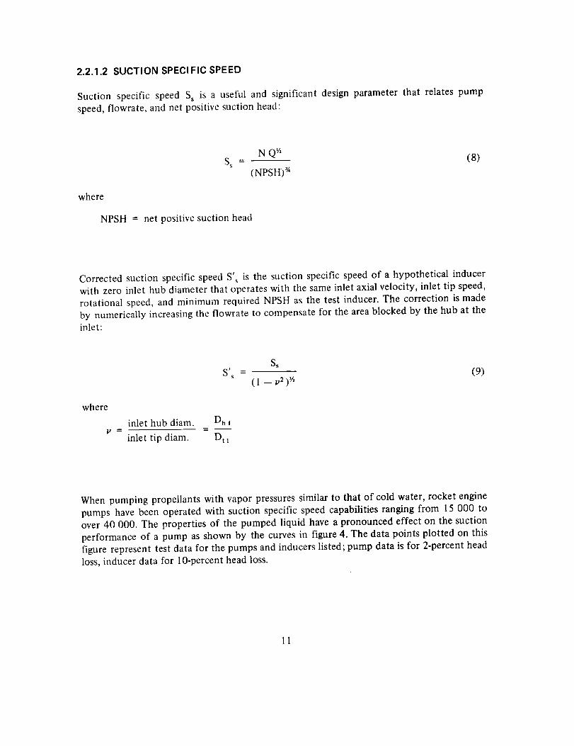
Suction specific speed Ss is a useful and significant design parameter that relates pump
speed, flowrate, and net positive suction head:
N QWS s =
(NPSH) _/"
where
NPSH = net positive suction head
(8)
Corrected suction specific speed S'_ is the suction specific speed of a hypothetical inducerwith zero inlet hub diameter that operates with the same inlet axial velocity, inlet tip speed,
rotational speed, and minimum required NPSH as the test inducer. The correction is made
by numerically increasing the flowrate to compensate for the area blocked by the hub at the
inlet:
Ss
S' s - (9)(1 -- v2) '/2
where
inlet hub diam. Dh =
v inlet tip diam. Dtl
When pumping propellants with vapor pressures similar to that of cold water, rocket engine
pumps have been operated with suction specific speed capabilities ranging from 15 000 toover 40 000. The properties of the pumped liquid have a pronounced effect on the suction
performance of a pump as shown by the curves in figure 4. The data points plotted on this
figure represent test data for the pumps and inducers listed; pump data is for 2-percent head
loss, inducer data for 10-percent head loss.
11

('4
!
C'4
I
v(#1
(/1
u
--_nul
4)
r_ut
U
q..,mU_U(2.ul
CO
4-pU-Iu1
qU4-/U
I.Lo
155
Ik5 --
135 --
125 --
115 --
lOS --
95--
85 --
75 --
6S --
55--
45 --
35 --
25 --
15
\Test fluid TemPeratures
......... wster * 5)5 ÷ I°RLH2 " )7 +" leRLOX - 16)'+ I°R
inlet tip
Pump or Inducer dog.
J-2 Hydr_an pump 7.]5Kark 25 nuclear feed _ 10.92
O hydrogen puap _ 11.10II,300 J-2S hydrogen pump 7.50
0 J'2S hydrogen pump {Improvlddesign) 7._
0 Hydrogen ttm-phase pump (ref. 40) 6.960 Atlas sustelner oxygen p_mp 9.00 F-I oxidizer p_lp O._4J
Scale model of F-I oxFdlzar Inducer 9.18J'2 oxidizer pump 9.85
III J-2S oxidizer pump 9.10• I/edged Inducer (ref, ]3) 7.0
Expt'l hubless Inducer 7.24(3 Shrouded fo_ard-st.ept Inducer (ref. 3)) 5.0O Expt'l Inducer driven by hydraulic turbine 7.5O Breadboard-engine oxygen-puap Inducer (raf. 45) 8.64 Breodbo3rd-engl_ hydrogen-pua p Inducer (ref. 45) £.0
8k° helical hydrogen Inducer (ref. k4_) 6.0
/I I I J I I I
•02 .04 .0& 0.8 .10 . 12 .14
Inlet tip flow coefficient,¢tl
Figure 4. - Summary of empirical data on suction performance of variouspumps and inducers.
Inlet tipdlam.p
In.
7.8e7.867 ;547.258.15
8.1511.334.91
15.756.547.2S7.255.358.06.765
6.31_9.4_._
12
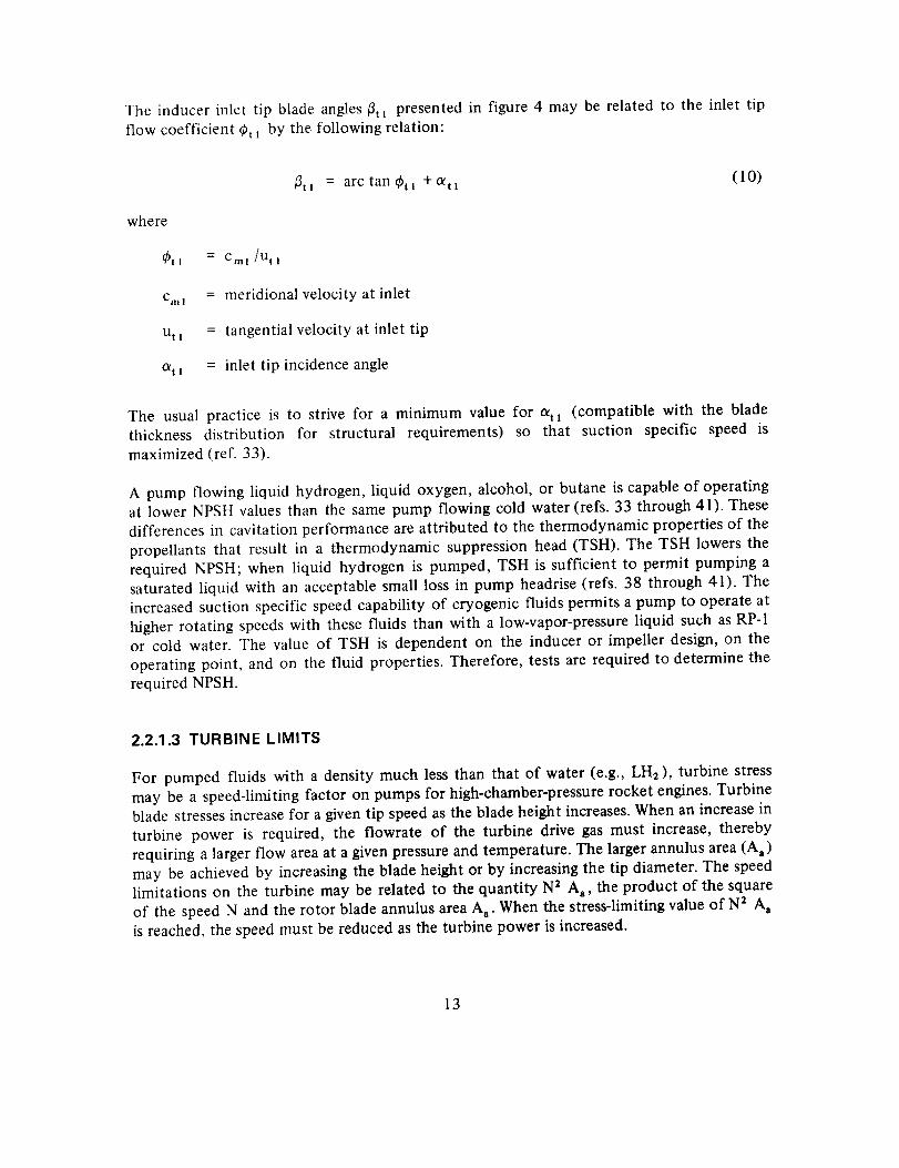
The inducer inlet tip blade angles _3tl presented in figure 4 may be related to the inlet tip
flow coefficient ¢h _ by the following relation:
/_t I = arc tan _t I -t- Ott !(10)
where
_ti = Cml /nil
cm_ = meridional velocity at inlet
u t _ = tangential velocity at inlet tip
at_ = inlet tip incidence angle
The usual practice is to strive for a minimum value for oql (compatible with the bladethickness distribution for structural requirements) so that suction specific speed is
maximized (ref. 33).
A pump flowing liquid hydrogen, liquid oxygen, alcohol, or butane is capable of operatingat lower NPSH values than the same pump flowing cold water (refs. 33 through 41). These
differences in cavitation performance are attributed to the thermodynamic properties of the
propellants that result in a thermodynamic suppression head (TSH). The TSH lowers the
required NPSH; when liquid hydrogen is pumped, TSH is sufficient to permit pumping asaturated liquid with an acceptable small loss in pump headrise (refs. 38 through 41). The
increased suction specific speed capability of cryogenic fluids permits a pump to operate at
higher rotating speeds with these fluids than with a low-vapor-pressure liquid such as RP-1or cold water. The value of TSH is dependent on the inducer or impeller design, on the
operating point, and on the fluid properties. Therefore, tests are required to determine the
required NPSH.
2.2.1.3 TURBINE LIMITS
For pumped fluids with a density much less than that of water (e.g., LH2), turbine stress
may be a speed-limiting factor on pumps for high-chamber-pressure rocket engines. Turbineblade stresses increase for a given tip speed as the blade height increases. When an increase in
turbine power is required, the flowrate of the turbine drive gas must increase, thereby
requiring a larger flow area at a given pressure and temperature. The larger annulus area (A a)
may be achieved by increasing the blade height or by increasing the tip diameter. The speedlimitations on the turbine may be related to the quantity N 2 A a, the product of the square
of the speed N and the rotor blade annulus area A a. When the stress-limiting value of N 2 A a
is reached, the speed must be reduced as the turbine power is increased.
13
Thequantity N2 Aa hasa maximumvaluedepending upon the materials of fabrication and
the operating temperature. The limiting stress relations are explained in greater detail in
reference 42. The turbine stress does not limit the rotating speeds for pumps handling fluidswith a density approximately that of water.
2.2.1.4 BEARING AND SEAL LIMITS
The bearing required to support the radial and axial loads of a rotating assembly has an
upper speed limit that is related to bearing size and to the required operating life. Bearing
speed limits are discussed in detail in reference 43. If rubbing shaft seals are required forminimum leakage, the maximum allowable rubbing speed combined with the shaft size aslimited by its torque capacity may limit the rotating speed. Reference 44 discusses shaft sealtypes and their speed limits.
If conventional nose-rubbing shaft seals wear too rapidly because of high rubbing speeds,
lift-off seals may be used. When the shaft is not rotating, a lift-off seal provides the lowleakage rate typical of the nose-rubbing seal. When the shaft is rotating, the lift-off seal is
actuated by a liquid or gas pressure source to separate the sealing surfaces to prevent
high-speed rubbing. During this mode of operation, the sealing function is provided by
noncontacting seals such as labyrinth seals, floating ring seals, hydrodynamic, or hydrostaticseals. Seal leakage greater than that of rubbing seals must be accepted.
Bearings may be located outboard of the rotating assembly so that the bearing diameter can
be smaller than the shaft diameter required by torque or critical speed. Outboard bearing
installations have been used on a feed-system turbine for a nuclear rocket engine. To date,
outboard bearings have not been used on a complete flight-system turbopump; however,their use is being given serious consideration in advanced designs.
2.2.2 Efficiency
The efficiency of a centrifugal pump is influenced by its operating conditions and by its
design. The operating conditions that most strongly contribute to pump efficiency arespeed, flowrate, and headrise. As shown in equation (I), these parameters are combined intothe pump specific speed Ns.
Specific speed has been used with flowrate Q as a parameter to characterize commercial
pump efficiency. Commercial pumps pumping water at certain values for Q and Ns havetypical sizes established for the most part by the driving electric motors. Rocket enginepumps, in particular hydrogen pumps, operate at speeds much higher than those of
commercial pumps; therefore, for a given flowrate and specific speed, rocket engine pumps
14
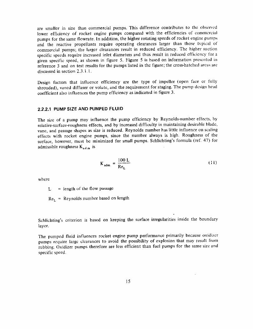
are smallerin size than commercialpumps.This differencecontributesto the observedlower efficiency of rocket enginepumps comparedwith the efficienciesof commercialpumpsfor thesameflowrate.In addition,thehigherrotatingspeedsof rocketenginepumpsand the reactivepropellantsrequire operatingclearanceslarger than those typical ofcommercialpumps;the largerclearancesresult in reducedefficiency.The highersuctionspecificspeedsrequireincreasedinlet diametersandthusresultin reducedefficiencyfor agivenspecificspeed,asshownin figure 5. Figure 5 is basedon informationpresentedinreference3 andon test resultsfor thepumpslistedin thefigure;thecross-hatchedareasarediscussedin section2.3.1.1.
Designfactors that influence efficiency are the type of impeller (open face or fullyshrouded),vaneddiffuseror volute,andtherequirementfor staging.Thepumpdesignheadcoefficientalsoinfluencesthepumpefficiencyasindicatedin figure3.
2.2.2.1 PUMP SIZE AND PUMPED FLUID
The size of a pump may influence the pump efficiency by Reynolds-number effects, by
relative-surface-roughness effects, and by increased difficulty in maintaining desirable blade,
vane, and passage shapes as size is reduced. Reynolds number has little influence on scalingeffects with rocket engine pumps, since the number always is high. Roughness of the
surface, however, must be minimized for small pumps. Schlichting's formula (ref. 47) for
admissible roughness Kad m is
100 LKadm - (1 1)
Re L
where
L
Re L
= length of the flow passage
= Reynolds number based on length
Schlichting's criterion is based on keeping the surface irregularities inside the boundary
layer.
The pumped fluid influences rocket engine pump performance primarily because oxidizer
pumps require large clearances to avoid the possibility of explosion that may result from
rubbing. Oxidizer pumps therefore are less efficient than fuel pumps for the same size and
specific speed.
15
X-8 LH2
Atlas booster RP-IAtlas booster LOXAtlas sustalner RP--I*Atlas sustainer L0XF-1 RPI ]F-I LOXJ-2 LOX
*No Inducer, Ss - 15000
Corrected suction specific speedwith coupled Inducer
(A) 40000(B) 20000(c) lOOOO
TSH - 0
I1.0 0.703 0.66614.25 0.613 0.720!1.0 0.596 0.785
8.60 0.589 0.7007.7 0.560 0.670
23.4 0.563 0.76019.5 0.487 0.74510.2 0.448 0.815
C 2NPSH " 3 "ml
2g
2
NPSH = 2 Cm--_-I2g
r/(values as noted)
0.8
07
_ o.6q
- 0.5
0.4;00
- _ - .65
II000
I I1500 2000
Stage specific speed
I I2500 3000
Figure 5. - Influence of impeller diameter ratio on pump performance.
8O
3500
]6
Pump
(_)Expt'l LF 2
(_Atlas Sustalner LOX
(_)Atlas Sustainer RP-i
(_)Redstone Oxidizer
(_)J-2 LOX
(_)XLR-129 LH 2 Ist Stage
(_Saturn I-B Booster LOX
(_) X-8 LH 2
(_Redstone Fuel
XLR-129 LH 2 2nd Stage
Saturn I-B Booster RP-I
Dr2 , in.
1.20 Volute
7.70 Vaneless Diffuser & Volute
8.60 Volute
9.65 Volute
10,20 Volute
10.62 Vaneless Diffuser & Volute
11.00 Vaned Diffuser & Volute
11.00 Vaned Diffuser & Volute
11.80 Volute
12.60 Vaneless Diffuser _ Volute
13.30 Vaned Diffuser & Volute
Impelle.rDiffuser Geometry Geometry
Shroud
Shroud
Shroud
Shroud
Shroud
Open Face
Shroud
Shroud
Shroud
Open Face
Shroud
_t
>_ 70
& 60
5c
I0 - Dr2
- 8
6
i
500 600 800 1000 1200 1600 2000
Stage specific speed
Figure 6. -- Influence of pump size on efficiency.
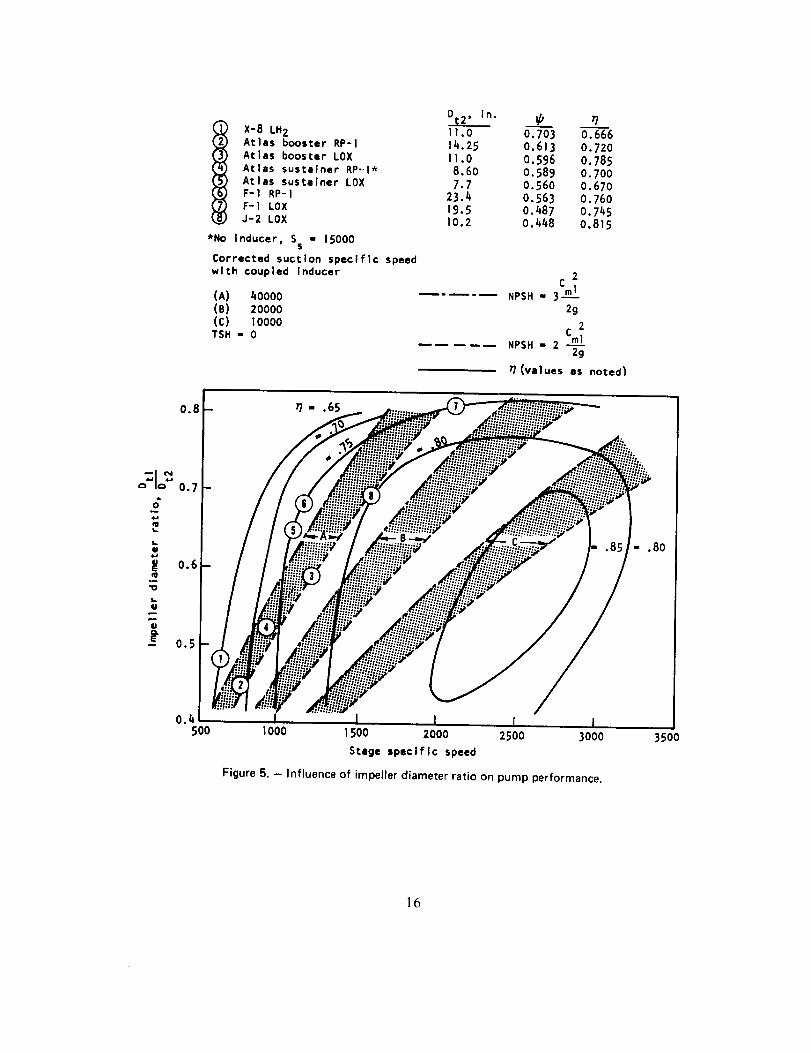
The influences of size and pumped fluid on pump efficiency are presented in figure 6. The
impeller discharge tip diameter Dr2 is used as the characteristic dimension. The curves arebased on material from the literature (ref. 48); test results for the pumps listed are
superimposed on the curves.
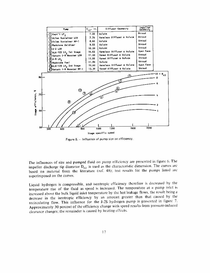
Liquid hydrogen is compressible, and isentropic efficiency therefore is decreased by the
temperature rise of the fluid as speed is increased. The temperature at a pump inlet is
increased above the bulk liquid inlet temperature by the hot leakage flows, the result being a
decrease in the isentropic efficiency by an amount greater than that caused by the
recirculating flow. This influence for the J-2S hydrogen pump is presented in figure 7.
Approximately 30 percent of the efficiency change with speed results from pressure-induced
clearance changes; the remainder is caused by heating effects.
17
8O
O
Ee
m
4.,
m
7O
6O
5O
4O I I I4 6 8 !0 12 x lO 3
Inlet flowrete, gpm
Figure 7. - Influence of speed on hydrogen-pump efficiency (J-2S).
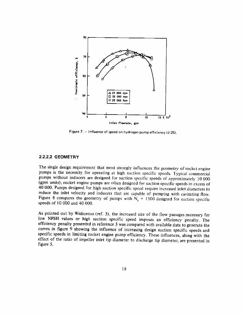
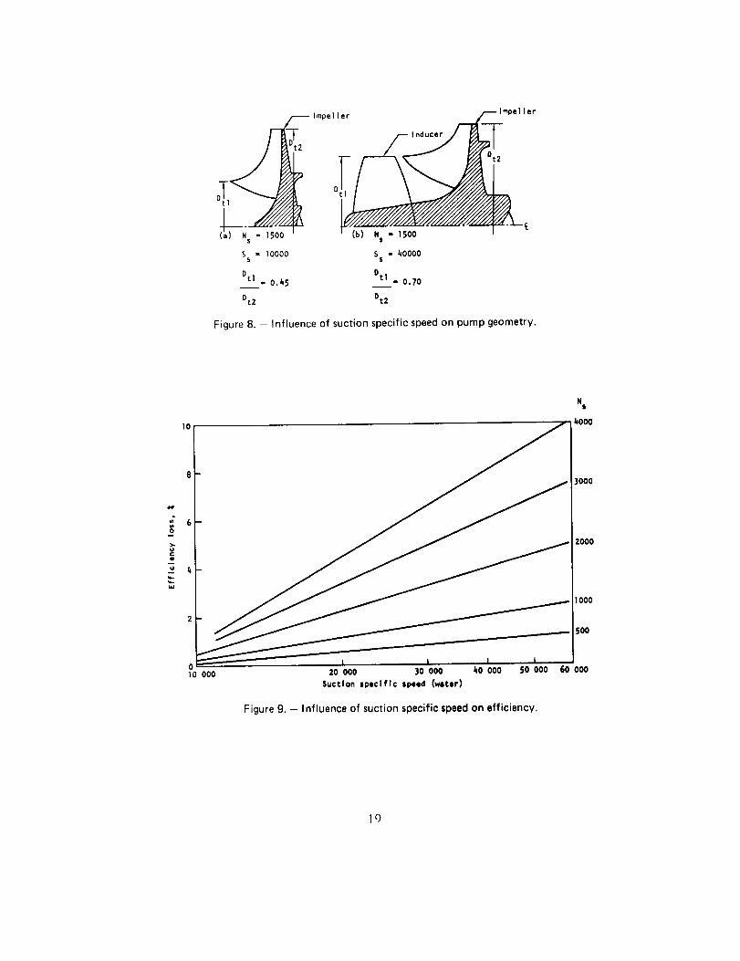
2.2.2.2 GEOMETRY
The single design requirement that most strongly influences the geometry of rocket enginepumps is the necessity for operating at high suction specific speeds. Typical commercial
pumps without inducers are designed for suction specific speeds of approximately 10 000
(gpm units); rocket engine pumps are often designed for suction specific speeds in excess of40 000. Pumps designed for high suction specific speed require increased inlet diameters to
reduce the inlet velocity and inducers that are capable of pumping with cavitating flow.
Figure 8 compares the geometry of pumps with N s = 1500 designed for suction specificspeeds of 10 000 and 40 000.
As pointed out by Wislicenus (ref. 3), the increased size of the flow passages necessary for
low NPSH values or high suction specific speed imposes an efficiency penalty. The
efficiency penalty presented in reference 3 was compared with available data to generate the
curves in figure 9 showing the influence of increasing design suction specific speeds and
specific speeds in limiting rocket engine pump efficiency. These influences, along with the
effect of the ratio of impeller inlet tip diameter to discharge tip diameter, are presented infigure 5.
18
lmpeller _lmpeller
/--,nOo;:/j
0t2D t
Ss 10000 Ss 40000
Dti = 0.45 °t_1_I = 0.70
Dt2 0t2
Figure 8. - Influence of suction specific speed on pump geometry.
Ns
1o kooo
3000
2000
1000
SO0
010 000 20 000 30 000 kO 000 SO 000 60 000
Suction specific speed (water)
Figure 9. - Influence of suction specific speed on efficiency.
Ic)
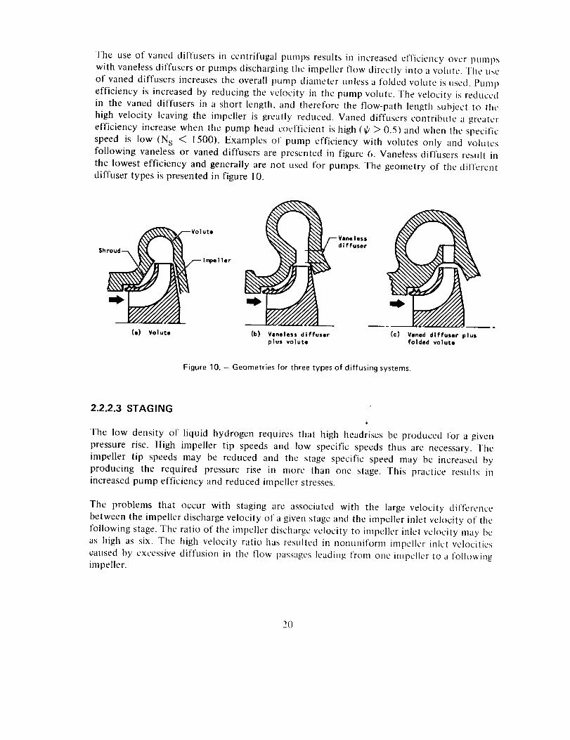
The use of vaned diffusers in centrifugal pumps results ill increased efficiency over i_Uml_S
with vaneless diffusers or pumps discharging tile impeller flow directly into a volute. Tile usc
of vaned diffusers increases the overall pump diameter tmless a folded volute is used. Pump
efficiency is increased by reducing the velocity in the pump volute. Tile velocity is reduced
in the vaned diffusers in a short length, and therefore the flow-path length subject to tile
high velocity leaving the impeller is greatly reduced. Vaned diffusers contribute a greater
efficiency increase when the pump head coefficient is high (_ > 0.5) and when the specific
speed is low (N s < 1500). Examples of pump efficiency with volutes only and volutes
following vaneless or vaned diffusers are presented in figure 6. Vaneless diffusers result in
the lowest efficiency and generally are not used for pumps. The geometry of the differentdiffuser types is presented in figure I0.
Sh roud--_ _Volute
(m) Volute (b) Vaneless diffuser
plus volute
Veneless
diffuser
(c) Vaned diffuser plusfolded volute
Figure 10. - Geometries for three types of diffusing systems.
2.2.2.3 STAGING
The low density of liquid hydrogen requires that high headrises be produced for a given
pressure rise. High impeller tip speeds and low specific speeds thus are necessary. The
impeller tip speeds may be reduced and the stage specific speed may be increased by
producing the required pressure rise in more than one stage. This practice results inincreased pump efficiency and reduced impeller stresses.
The problems that occur with staging are associated with the large velocity difference
between the impeller discharge velocity of a given stage and the impeller inlet velocity of the
following stage. The ratio of the impeller discharge velocity to impeller inlet velocity may be
as high as six. The high velocity ratio has resulted in nonunifoml impeller ink, t velocities
c-aused by excessive diffusion in the flow passages leading from one impeller to a followingimpeller.
2O
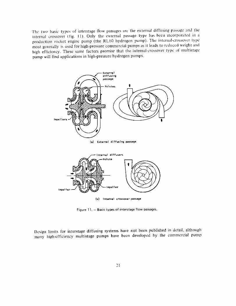
The two basictypesof interstageflow passagesaretheexternaldiffusingpassageand theinternal crossover(fig. 11). Only the external passagetype hasbeenincorporatedin aproductionrocketenginepump (the RLIO hydrogenpump).The internal-crossovertypemostgenerallyis usedfor high-pressurecommercialpumpsasit leadsto reducedweightandhighefficiency.Thesesamefactorspromisethat the internal-crossovertype of multistagepumpwill find applicationsin high-pressurehydrogenpumps.
/4__ Extarnal
diffusing
passage
Impel lers__
(a) External dlffuslng passage
I nternal diffusers
--Volute
1mpel ler
(b) Internal crossover passege
Figure 11. - Basic types of interstage flow passages.
Design limits for interstage diffusing systems have not been published in detail, although
many high-efficiency multistage pumps have been developed by the commercial pump
21
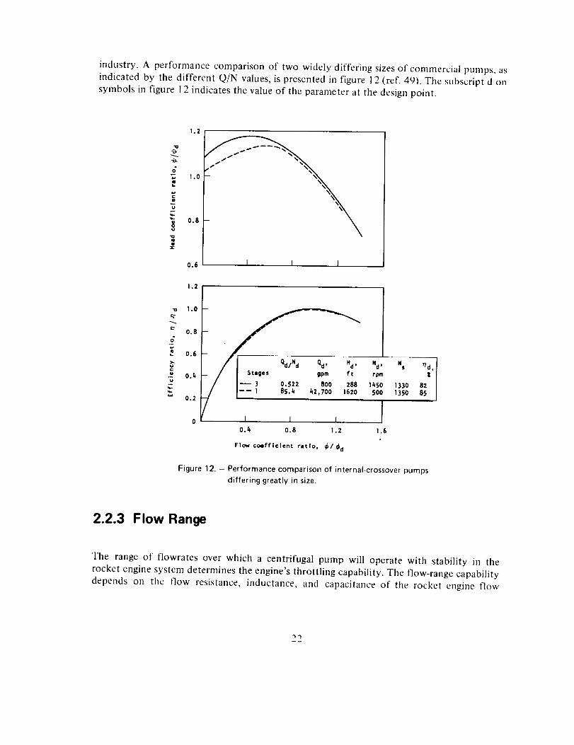
industry.A performancecomparisonof two widelydifferingsizesof commercialpumps,asindicatedby the differentQ/N values,ispresentedin figure12(ref. 49).Thesubscriptd onsymbolsin figure 12indicatesthevalueof theparameterat thedesignpoint.
1.2
_.y
&
1.0
U
_- 0.8
=-
0.6
1.2
g 1.0
0.8o"
0.6
• 0.4m
0.2
\1 i I
t ges gpm ft
0.522 800 28885.4 42,700 1620
Nd , Ns r/d,
rpm t
1450 1330 82500 1350 85
t I I0.4 0.8 1.2
Flow coefficient tit[o, _1 _ld
[1.6
Figure 12. - Performance comparison of internal-crossover pumps
differing greatly in size.
2.2.3 Flow Range
Tile range of flowrates over which a centrifugal pump will operate with stability in the
rocket engine system determines the engine's throttling capability. The flow-range capability
depends on the flow resistance, inductance, and capacitance of the rocket engine flow
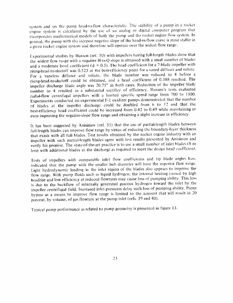
systemand on the pump head-vs-flowcharacteristic.]_laestability of a pumpin a rocketenginesystemis calculatedby the useof an analogor digital computerprogramthatincorporatesmathematicalmodelsof both the pumpandtherocketengineflow system.Ingeneral,thepumpwith thesteepestnegativeslopeof thehead-vs-flowcurveismoststableinagivenrocketenginesystemandthereforewill operateoverthewidestflow range.
Experimentalstudiesby Hansen(ref. 50) with impellershavingfull-lengthbladesshowthatthe widestflow rangewith anegativeH-vs-Qslopeisobtainedwith asmallnumberof bladesand a moderateheadcoefficient(ff = 0.5).Theheadcoefficientfor a 7-bladeimpellerwithrising-head-to-shutoffwas0.523at thebest-efficiencypoint for avaneddiffuserandvolute.For a vanelessdiffuser and volute, the blade number was reducedto 4 before arising-head-to-shutoffcould be obtained,and a head coefficientof 0.388 resulted.Theimpellerdischargebladeanglewas20.75° in both cases.Reductionof the impellerbladenumber to 4 resulted in a substantialsacrificeof efficiency.Hansen'stestsevaluatedradial-flow centrifugalimpellerswith a limited specificspeedrangefrom 700 to 1300.ExperimentsconductedonexperimentalF-I oxidizerpumpsdemonstratedthat thenumberof blades at the impeller dischargecould be doubled from 6 to 12 and that thebest-efficiencyheadcoefficientcouldbe increasedfrom 0.42 to 0.49 whilemaintainingorevenimprovingthenegative-slopeflow rangeandobtainingaslightincreasein efficiency.
It hasbeensuggestedby Anisimov(ref. 51) that the useof partial-lengthbladesbetweenfull-lengthbladescanimproveflow rangebyvirtueof reducingtheboundary-layerthicknessthat existswith all full blades.Test resultsobtainedby the rocketengineindustrywith animpellerwith suchpartial-lengthbladesagreewith test resultspresentedby Anisimovandverify hispremise.The state-of-the-artpracticeis to useasmallnumberof inlet blades(8 orless)with additionalbladesat thedischargeasrequiredto meetthedesignheadcoefficient.
Testsof impellerswith comparableinlet flow coefficients and tip blade angles haw '
indicated that the pump with the smaller hub diameter will have the superior flow range.
Light hydrodynamic loading in the inlet region of the blades also appears to improve the
flow range. With pump fluids such as liquid hydrogen, the internal heating cat_sed by high
headrise and low efficiency at reduced flowrates may cause loss of pumping ability. This loss
is due to the backflow of internally generated gaseous hydrogen toward the inlet by the
impeller centrifugal field. Increased inlet pressures delay such loss of pumping ability. Pump
bypass as a means to improve flow range is limited to the amount that will result in 20
percent, by volume, of gas flowrate at the pump inlet (refs. 39 and 40).
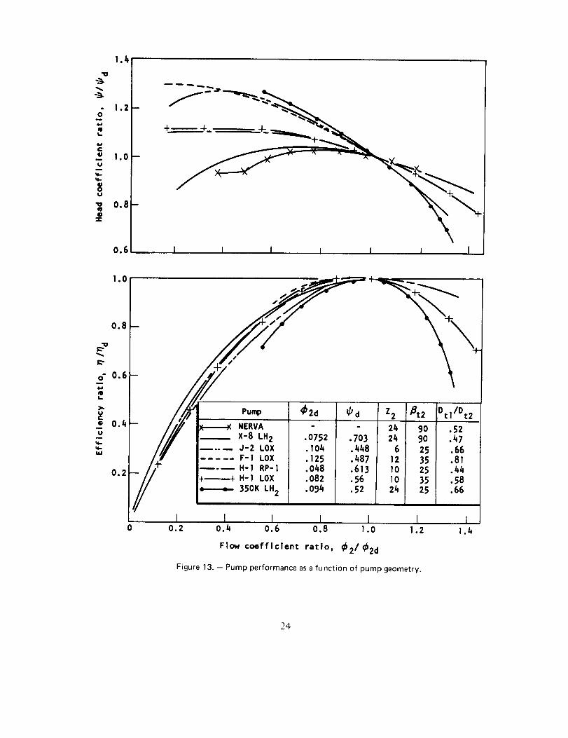
Typical pump performance as related to pump geometry is presented in figure 13.
23
1.4
,; I.z4.1QI,.
¢
3 1.oU
U
-o 0.8QtP
0.6i I I I
eu._ _ 2d _ dNERVAX-8 LH2 .0752J-2 LOX .I04F-I LOX .125H-1RP-1 .048
+÷_ H-I LOX .082
350K LH2 .094
.703.448.487.613.56.52
Z2 _t2 Dtl/Dt2
24 90 .5224 90 .47
6 25 .6612 35 .8110 25 .44I0 35 .5824 25 .66
.1_ l L t I____J0.2 0.4 0.6 0.8 1.0 I .2
Flow coefficient ratio, _2/_2d
Figure13. - Pumpperformanceasafunction of pump geometry.
24
2.3 IMPELLER
The impeller of a centrifugal pump converts the input shaft power into tile static presstire
rise and velocity energy of the pumped lluid. The velocity energy leaving the impeller is
converted, for tile most part, to static presstire in tile pump housing. The impeller nnlst
deliver the design discharge flowrate plus any internal leakage or auxiliary flows and provide
sufficient presstlre rise to overcome the internal pump presstlre losses while achieving tile
design pressure rise. The impeller must operate at the inlet presstire available from the
vehicle, from a direct-coupled inducer, or from a separate low-pressure pump. The materials
from which the impeller is fabricated must be compatible with the pumped fluids, the
torque loads, and the tip speeds required to generate the presstire rise. The impeller axial
and radial clearances during operation must be sufficient to avoid rubbing. The impeller may
incorporate an integral inducer, a separate inducer, or no inducer at all. The impeller may be
fully shrouded, open faced, or completely unshrouded. Completely unshrouded impellers
have had limited use. The considerations involved in successful impeller design are discussed
in detail in the following sections.
2.3.1 Hydrodynamic Design
Once the pump speed has been selected, the impeller design can then be accomplished. The
overall pump head-vs-flow characteristics are largely dependent upon the impeller design
that establishes the pump head coefficient _ (eq. (7)). The pump head coefficient _ is
determined by the impeller discharge flow coefficient _2 • discharge blade angle/32 ; and the
impeller discharge blade number Z2, which itself is a function of shroud stress, tip speed, 32,
and fabrication method; thus
= f(_2,_2, Z2)12 (12)
The impeller suction specific speed S_ is determined by the inlet flow coefficient _b_, the
inlet angle 3_, the inlet-hub-to-inlet-tip diameter ratio v, and the inlet blade thickness tl:
S_ = f(_l,31,v, tl) :1.< (13)
The impeller and overall pump efficiency are influenced by tile surface finish of impeller
flow path, the ratio of inlet tip to discharge tip diameter, and impeller seal and rotor
clearances.
Efficient impeller designs such as those for the pumps in the Atlas and Titan booster engine
systems have been developed by considering one-dimensional flow theory stipplemented
with empirical data. In more recent work, however, quasi-three-dimensional analyses are
25
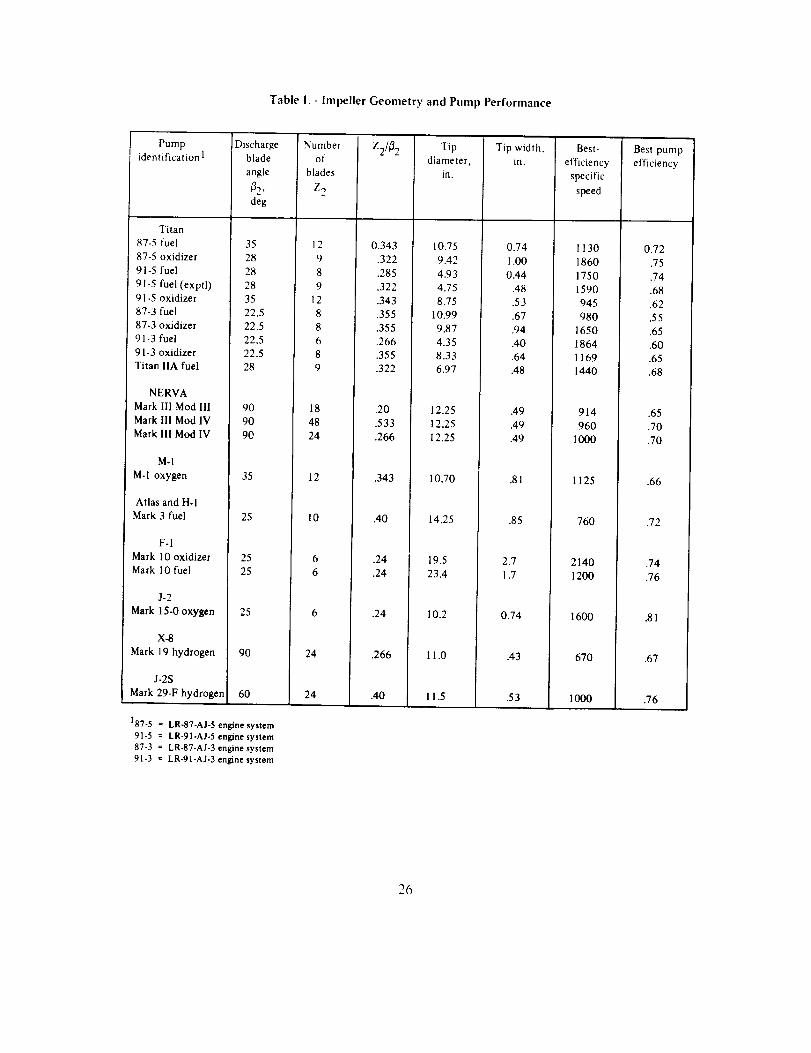
Table I. - Impeller Geometry and Pump Performance
Pump
identification 1
Titan
87-5 fuel
87-5 oxidizer
91-5 fuel
91-5 fuel (exptl)
91-5 oxidizer
87-3 fuel
87.3 oxidizer
91-3 fuel
91-3 oxidizer
Titan IIA fuel
NERVA
Mark llI Mod Ill
Mark Ill Mod IV
Mark Ill Mod IV
M-I
M-1 oxygen
Atlas and H-I
Mark 3 fuel
F-1
Mark I 0 oxidizer
Mark 10 fuel
J-2
Mark 15-0 oxygen
X-8
Mark 19 hydrogen
J-2S
Mark 29.F hydrogen
[Discharge Number
blade of
angle blades
.B2 , Z 2
deg
35 12
28 9
28 8
28 9
35 12
22.5 8
22.5 8
22.5 6
22.5 8
28 9
90 18
90 48
90 24
35 12
25 10
25 6
25 6
25 6
90 24
60 24
187-5 = LR-87-AJ-5 engine system
91-5 = LR-91-AJ-5 engine system87-3 = LR-87-AJ-3 engine system
91-3 = LR-91-AJ-3 engine system
Z2/_ 2
0,343
.322
.285
.322
.343
.355
.355
.266
.355
.322
.20
.533
.266
.343
.40
.24
.24
.24
.266
.40
Tip
diameter,
in.
10.75 0.74
9.42 1.00
4.93 0.44
4.75 .48
8.75 .53
10.99 .67
Tip width, Best-
in. efficiency
specific
speed
1130
1860
1750
1590
945
980
9.87
4.35
8.33
6.97
12.25
12.25
12.25
10.70
14.25
19.5
23.4
10.2
11.0
11.5
.94
.40
.64
.48
.49
.49
.49
.81
.85
2.7
1.7
0.74
.43
.53
1650
1864
1169
1440
914
960
1000
1125
760
2140
1200
1600
670
1000
Best pump
efficiency
0.72
.75
.74
.68
.62
.55
.65
.60
.65
.68
.65
.70
.70
.66
.72
.74
.76
.81
.67
.76
26
used to estimate more accurately the velocity distributions within the impeller. Tile velocity
gradients then are evaluated for the possible occurrence of flow eddies or flow separation.
The impeller blade angle distribution and the blade number are adjusted until desired design
limits are achieved.
Representative ilnpeller geometries and associated pumt_ performance are presented in table
I.
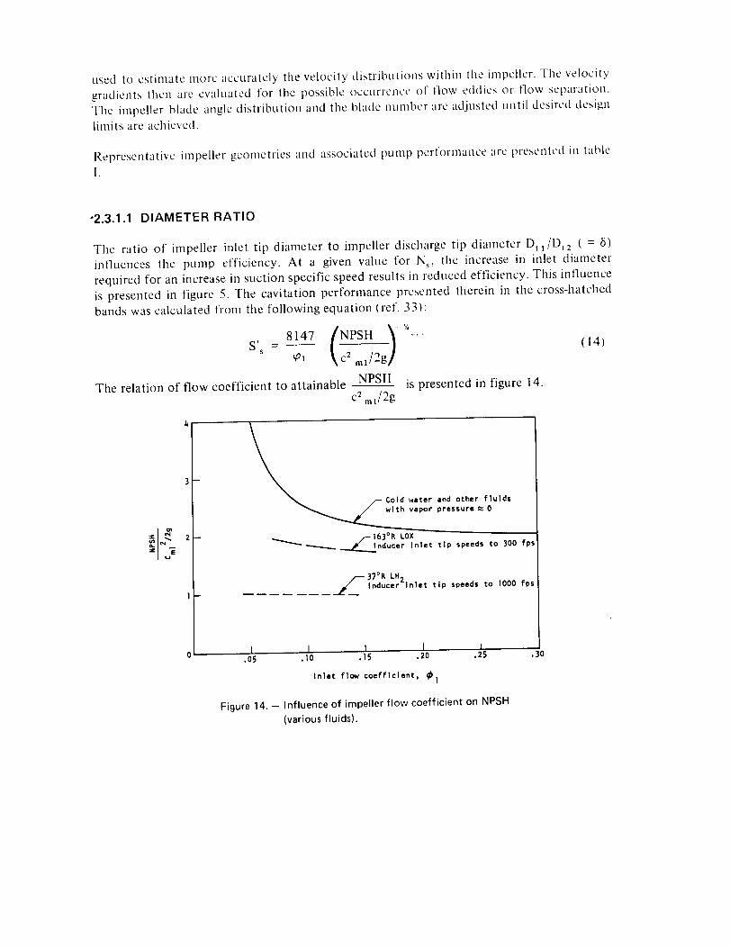
"2.3.1.1 DIAMETER RATIO
The ratio of impeller inlet tip diameter to impeller discharge tip diameter [)tl/Dt2 ( = 6)
influences the pump efficiency. At a given value for N s, the increase in inlet diameter
required for an increase in suction specific speed results in reduced efficiency. This influence
is presented in figure 5. The cavitation performance presented therein in the cross-hatched
bands was calculated from the following equation (ref. 33):
S' - 8147 N__PStt . _,' (14)
s ¢' IkcZ ml/:g}'
The relation of flow coefficient to attainable NPSH is presented in figure 14.c 2 ml/2g
4
3--
2 --
1-
_% ¢S Col d water and other fluids
with vapor pressure _ 0
f-163°R LOX_'-" _ ___.._nducer Inlet tlp speeds to 300 fp_
__ 37°R LH2Inducer tnlet tlp speeds to 1000 fps
t I I I i,05 ,10 ol5 .20 °25
Inlet flow coefficient, _1
Figure 14. - Influence of impeller flow coefficient on NPSH
(various fluids).
.3O
The higher values for 6 result in a higher inlet relative velocity caused by the higher
peripheral velocity. The higher inlet relative velocity increases the impeller diffusion and
results in lower efficiency. Efficiency of most rocket engine pumps is compromised to
permit operation at low inlet pressures. The use of a low-pressure boost punlp permitsoptimization of main pump efficiency.
2.3.1.2 HEAD AND FLOW COEFFICIENTS
The pump head coefficient and tile resulting impeller discharge diameter can have a wide
range of values depending upon the flowrate, required suction perl'ormance, the required
pump efficiency, and the head-vs-flow slope. Centrifugal-pump head coefficients vary from
approximately 0.35 to more than 0.70. The lower head coefficients are obtained with a
small number of blades (3 to 5); the higher head coefficients require many blades (20 to
60). More blades are required at a given head coefficient if the impeller discharge flow
coefficient is decreased; this relation is covered in more detail in section 2.3.1.3. Head
coefficient is not limited by flow coefficient. Higher head coefficients are generally used for
low-specific-speed applications, since efficiency is thereby maximized and the small inlet
diameter permits maximum blade length. With high-specific-speed pumps, low head
coefficients are accepted in order to achieve the blade length along the shroud needed for
good efficiency over a wide flow range.
The longer blade length results from tile increased tip diameter associated with decreased
head coefficient and from the reduced blade angle required to achieve the lower head
coefficient. Both the impeller inlet and discharge flow coefficients may vary from as low as
0.05 to 0.30. Tile impeller inlet flow coefficient _)1 is selected to satisfy tile required suction
performance, whereas the impeller discharge flow coefficient q_2 is determined by the
impeller blade angle as limited by stress and the desired head coefficient. The higher flow
coefficients are possible only for high-specific-speed, high-NPSH pumps.
The NPSH required as a function of inlet flow coefficient is presented in figure 14 for
sharp-leading-edge impellers (coupled inducers). The discharge flow coefficient is established
by the desired head coefficient and a practical blade number based on fabrication limits.
Tile discharge meridional component of velocity c m 2 may vary from 1 to 1.5 times the
impeller inlet velocity. The inlpeller inlet velocity is considered to be the velocity at the exit
of a coupled inducer or at the equivalent exit of an integral inducer.
The off-design performance requirements of the engine system during starts or throttling
often govern the selection of the head coefficient, because this coefficient largely
determines the nature of the pump head-vs-capacity curve. To verify system stability over
the entire operating range, the slope of the head/capacity curve is compared with the engine
system pressure drop characteristics and capacitance. An analog computer is often used for
28
thispurposeasdiscussedin reference1.Thepumphead/capacitycurveisdeterminedlargelyby headcoefficient(fig. 13).For pumpswith agivenheadcoefficient,animpellerwith thelargestbladenttmberwill resultin thesteepestslope.
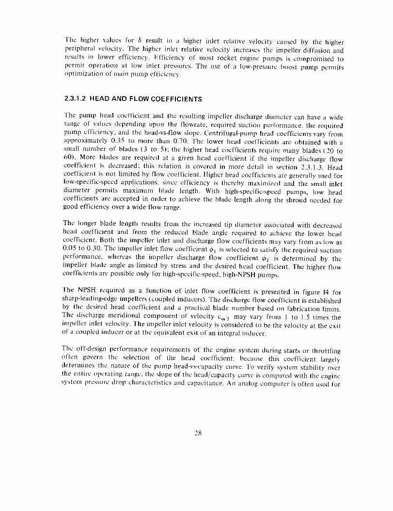
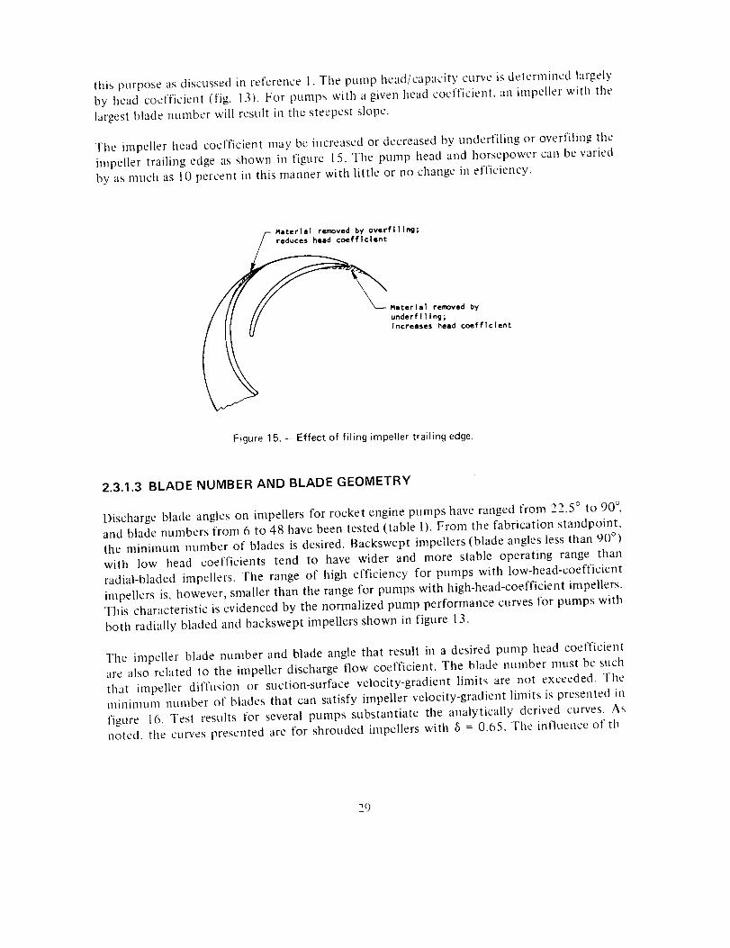
Tile impellerheadcoefficientmaybeincreasedor decreasedby underfilingor overfilingtheimpellertrailingedgeasshownin figure 15.Thepump headand horsepowercanbevariedby asmuchas10percentin thismannerwith little or nochangein efficiency.
Materlal removed by overfillng;/- reduces head coefficient
Material removed by
underflllng;increases head coefficient
Figure 15. - Effect of filing impeller trailing edge.
2.3.1.3 BLADE NUMBER AND BLADE GEOMETRY
Discharge blade angles on impellers for rocket engine pumps have ranged from 22.5 ° to 90 °,
and blade numbers from 6 to 48 have been tested (table I). From the fabrication standpoint,
the minimum number of blades is desired. Backswept impellers (blade angles less than 90 °)
with low head coefficients tend to have wider and more stable operating range than
radial-bladed impellers. The range of high efficiency for pumps with low-head-coefficient
impellers is, however smaller than the range for pumps with high-head-coefficient impellers.
This characteristic is evidenced by the normalized pump performance curves for pumps with
both radially bladed and backswept impellers shown in figure 13.
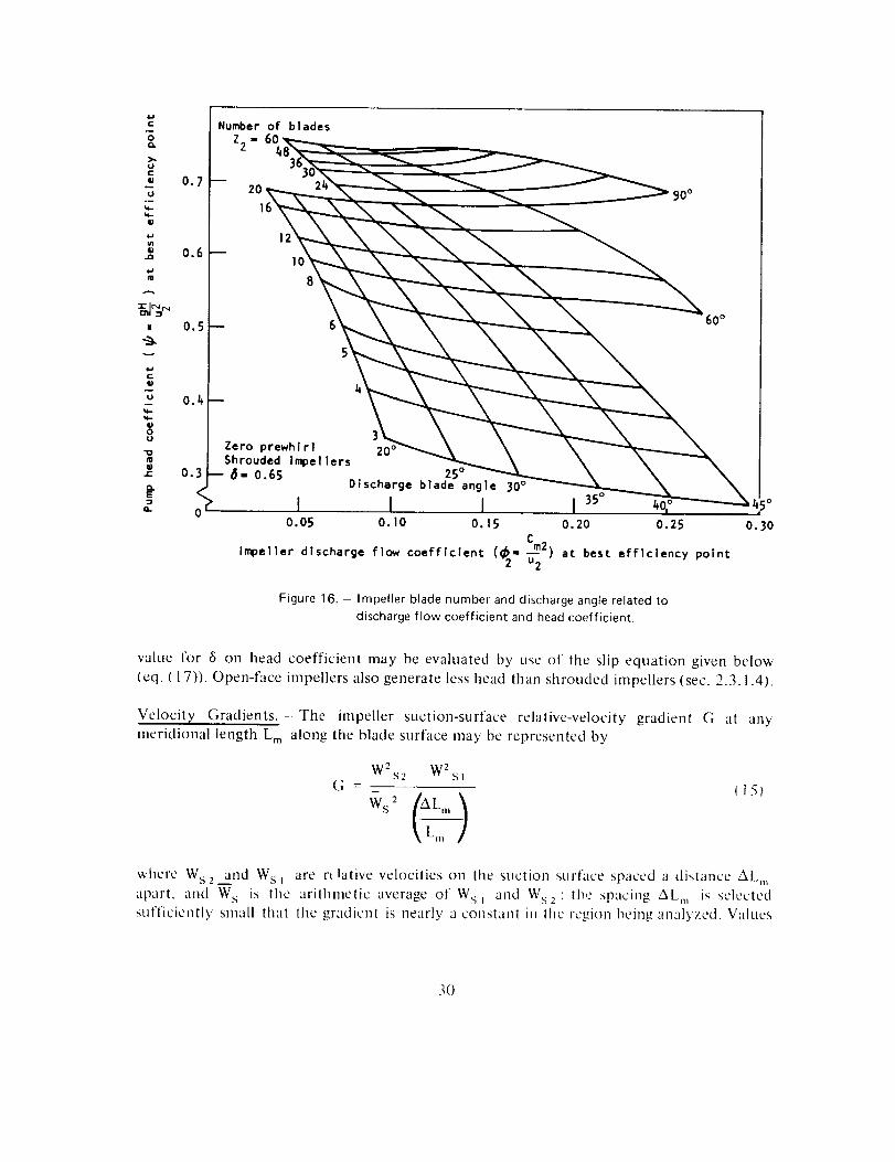
The impeller blade number and blade angle that result in a desired pump head coefficient
are also related to the impeller discharge flow coefficient. The blade number must be such
that impeller diffusion or suction-surface velocity-gradient limits are not exceeded. The
minimum number of blades that can satisfy impeller velocity-gradient limits is presented in
figure 16. Test results for several pumps substantiate the analytically derived curves. Asnoted, the curves presented are for shrouded impellers with 8 = 0.65. The influence of tb
29
Number of blades
Z2 - 6(
12
I0
8
6
S
60 °
Zero prewhlrl 20 °Shrouded Impellers
-- 6- 0.65 25°Discharge blade angle 30 °
I I Io.os o.,o O.lS
Impeller discharge flow coefficient (_2" Cm2)u2
I 3s° 40,° ,4s°o.2o o.2s 0.30
at best efficiency point
Figure 16. - Impeller blade number and discharge angle related to
discharge flow coefficient and head coefficient.
value for 6 on head coefficient may be evaluated by use of the slip equation given below
(eq. ( 17)). Open-face impellers also generate less head than shrouded impellers (sec. 2.3.1.4).
Velocity Gradients. The impeller suction-surface relative-velocity gradient G at anymeridional length Lm along the blade surface may be represented by
G
W2s2 W2sl
ws2\L,,, /
_15_
where Ws2 and Wsi are n lative velocities 011 tile suction surface spaced a distance AL,,,
apart, and W s is the arithmetic average of Ws_ and W s2' the spacing ALm is selected
sufl'iciently small thtit the gradient is nearly a conslant in the ]'egion being an__il$'zed. V,:ll!Jes
3O

forGas high as 3.5 have resulted in acceptable performance when the pressure surface
relative velocity is simultaneously in the direction of flow and greater than zero.
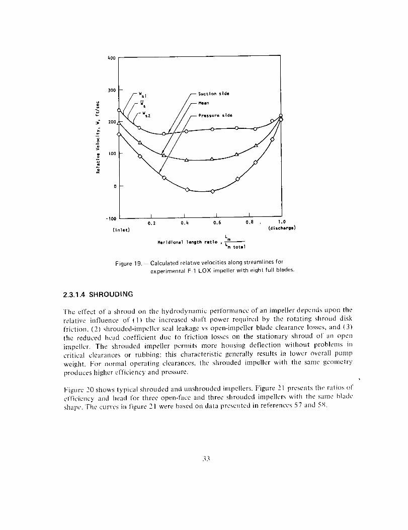
The relative velocities on the impeller blade surface are calculated by procedures presented
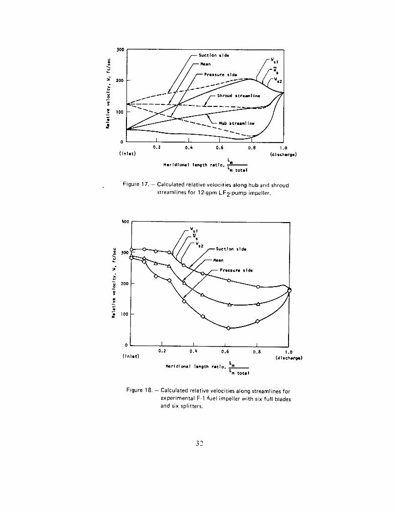
in references 52 through 54. Examples of acceptable gradients are presented in figures 17
(ref. 55) and 18; an unacceptable gradient is presented in figure 19, which shows both a
rapid drop in suction surface velocity near the inlet and a reversed velocity on the pressure
side of the blades.
Slip Coefficient. -- The inability of an impeller with a finite number of blades to impart the
same tangential whirl to the fluid as an impeller with an infinite number of blades is
represented by the slip coefficient M:
Cu2 _ ( 16_M-
cu2
where
%2_ = tangential velocity with infinite number of blades
Cu2 = tangential velocity with a given number of blades
A review of the literature shows that many proposed methods for predicting slip exist (ref.
56): however, no universal equation has been formulated. The methods of Buseman,
Pfliederer, Stanitz, and Stodola are still widely accepted (ref. 4). The empirically derived
expression for M:( 1.37 + 0.23 sin _2 ) (,_2 4- 0.05) 0.6
M = 1+ (i7)0.5Z 2(XL) °6(I+XL/2)(I .0.126)
axial distance from midpoint of impeller inlet to impeller discharge
where XL = impeller discharge diameter
was used along with hydrodynamic loading limits and velocity gradients established by
quasi-three-dimensional flow analyses of several impeller designs to develop the impeller
design influence on head coefficient presented in figure 16.
A small number of blades Z2 reduces the tangential velocity %2 leaving the impeller and
therefore reduces the head coefficient. A low head coefficient obtained by use of a small
,mnlber of blades and a large slip coefficient may not result in a steep head/tlow
characteristic. The steepest head/flow characteristic for a given head coefficient is obtained
with a value for M closely approaching unity, a condition that occurs when the number of
blades is large (Z2 > 20).
31
4.S
J
.s
3OO
200
100
0
{Inlet)
//_/__eSuct Ion side
in WsIPressure side __s
0.2 0.4 0.6 0.8 1,0
(d I scharge)L
Rerldlonal length retlo, ,m% total
Figure 17. - Calculated relative velocities along hub and shroud
streamlines for 12-gpm LF2-pum p impeller.
1_oo
>-
=-
3O0
2O0
I0O
_/s_r--Suctlon side
0 I I I I0.2 0.4 0.6 0.8 1.0
(Inlet) (discharge)L
Merldlonel length ratio, mLm totll
Figure 18. - Calculated relative velocities along streamlines for
experimental F-1 fuel impeller with six full blades
and six splitters.
32
_a
"GO
400
300
200
IO0
- IOO
(Inlet)
LS Wsl f Suction side
/:),, //-E,u,.,,°.
I I I0.2 0.4 0.6 0.8
Lm
Rerldlonal length rltlo p Lm total
I.0
(d I schmrge)
Figure 19. - Calculated relative velocities along streamlines forexperimental F-1 LOX impeller with eight full blades.
2.3.1.4 SHROUDING
The effect of a shroud on the hydrodynamic perfomlance of an impeller depends upon the
relative influence of (1) the increased shaft power required by the rotating shroud disk
friction, (2) shrouded-impeller seal leakage vs open-impeller blade clearance losses, and (3)
the reduced head coefficient due to friction losses on the stationary shroud of an open
impeller. The shrouded impeller permits more housing deflection without problems in
critical clearances or rubbing: this characteristic generally results in lower overall pump
weight. For normal operating clearances, the shrouded impeller with the same geometry
produces higher efficiency and pressure.
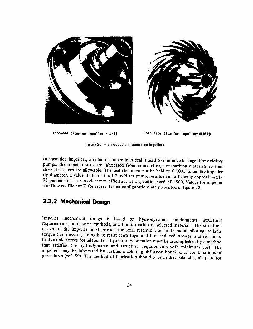
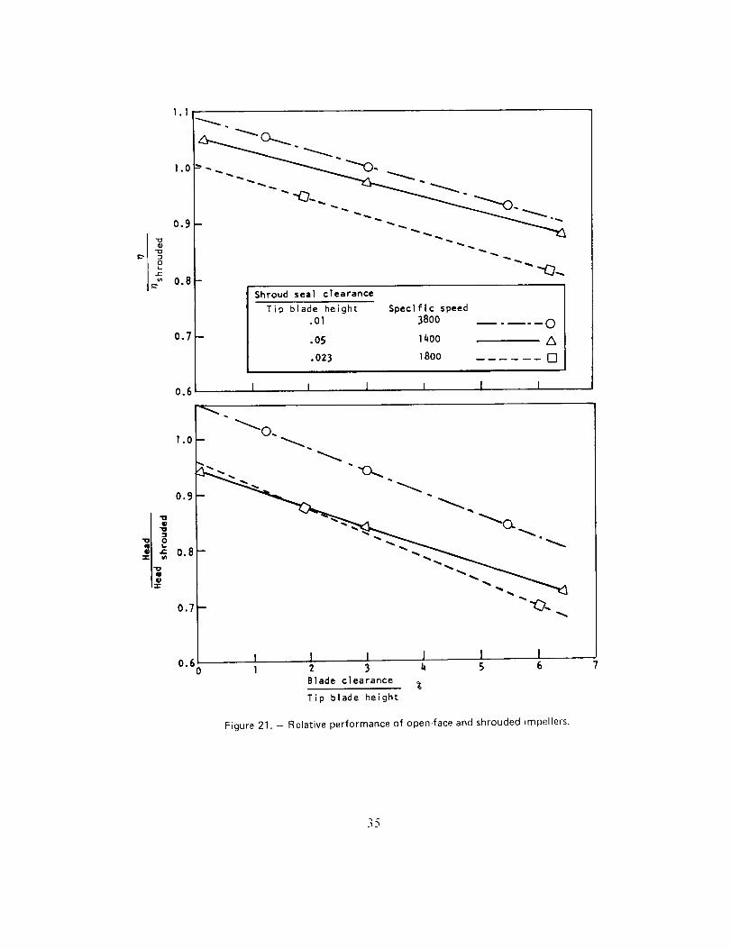
Figure 20 shows typical shrouded and unshrouded impellers. Figure 21 presents the ratios of
efficiency and head for three open-face and three shrouded impellers with the same blade
shape. Tile curves in figure 21 were based on data presented in references 57 and 58.
33
\
Shrouded titanium Impeller - J-2S Open-face titanium Impel|er-XLRI29
Figure 20. - Shrouded and open-face impellers.
In shrouded impellers, a radial clearance inlet seal is used to minimize leakage. For oxidizerpumps, the impeller seals are fabricated from nonreactive, nonsparking materials so that
close clearances are allowable. The seal clearance can be held to 0.0005 times the impeller
tip diameter, a value that, for the J-2 oxidizer pump, results in an efficiency approximately
95 percent of the zero-clearance efficiency at a specific speed of 1500. Values for impellerseal flow coefficient K for several tested configurations are presented in figure 22.
2.3.2 Mechanical Design
Impeller mechanical design is based on hydrodynamic requirements, structural
requirements, fabrication methods, and the properties of selected materials. The structural
design of the impeller must provide for axial retention, accurate radial piloting, reliable
torque transmission, strength to resist centrifugal and fluid-induced stresses, and resistance
to dynamic forces for adequate fatigue life. Fabrication must be accomplished by a methodthat satisfies the hydrodynamic and structural requirements with minimum cost. The
impellers may be fabricated by casting, machining, diffusion bonding, or combinations of
procedures (ref. 59). The method of fabrication should be such that balancing adequate for
34
I;
1.1
!.0
0.9
O.8
0.7
0.6
Shroud seal clearance
Tip blade height Speclflc speed
.ol 3800 ..... O
.05 1400 A
.023 1800 [7
I I J i I I ,,
l.O
0.9
°• _ 0.8T u_
0.7
0.(0
_0.
I I I I I I1 2 3 b, 5 6
Blade clearance %
Tip blade height
Figure 21. - Relative performance of open-face and shrouded impellers.
35
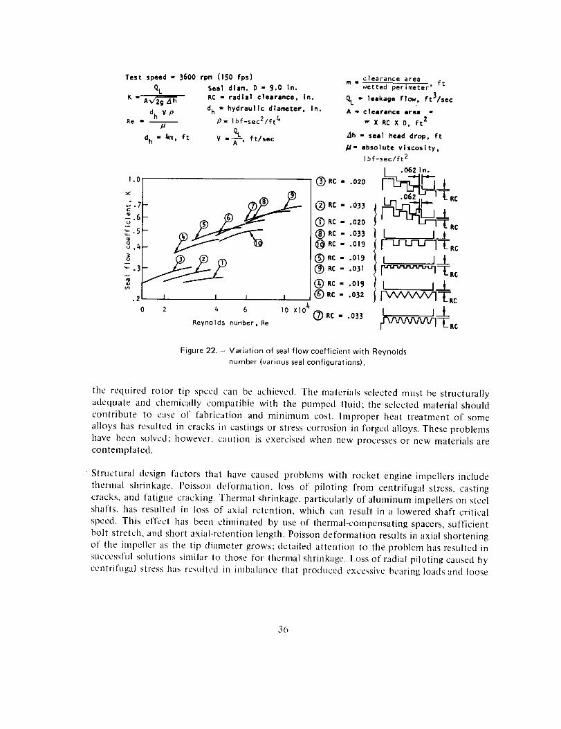
Test speed - 3600 rpm (150 fps)
QL
dh V pRe I I
dh - 4m, ft
Seal diam. D - 9.0 In.RC - radial clearance, In.
dh - hydraulic diameter, In.p- Ibf-sec2/ft 4
V --_-_', ft/sec
1.O
I 1
6 1o XlO 4
Reynolds number, Re
(_RC -
(_)RC -
(_RC -
(_)RC -
(_RC -
(_RC .
(_ RC -
(_)RC -
(_)RC -
(_RC m
clearance aream - wetted perimeter' ft
01. - leakage flow, ft3/sec
A - clearance area -
X RC X D, ft 2
_h - seal heed drop, ft
p- absolute viscosity,lbf-sec/ft 2
I ,0621n.
o2o -'[R¢
.033 L
.020 --[-RC
.os3 I It
.o,s --L-Rc
.ol9 I I_L
.o31 c
.o,9 t t I__L.035 (vvvvvv3-{-.c.033 I I_L
Figure 22. - Variation of seal flow coefficient with Reynolds
number (various seal configurations).
the required rotor tip speed can be achieved. The materials selected must be structurally
adequate and chemically compatible with the pumped fluid; the selected material should
contribute to ease of fabrication and minimum cost. Improper heat treatment of some
alloys has resulted in cracks in castings or stress corrosion in forged alloys. These problems
have been solved; however, caution is exercised when new processes or new materials are
contemplated.
• Structural design filctors that have caused problems with rocket engine impellers include
thermal shrinkage, Poisson deformation, loss of piloting from centrifugal stress, casting
cracks, and fatigue cracking. Thermal shrinkage, particularly of aluminum impellers on steel
shafts, has resulted in loss of axial retention, which can result in a lowered shaft critical
speed. This effect has been eliminated by use of thermal-compensating spacers, sufficient
bolt stretch, and short axial-retention length. Poisson deformation results in axial shortening
of the impeller as the tip diameter grows; detailed attention to the problem has resulted in
successflfl solutions similar to those for thermal shrinkage. Loss of radial piloting caused by
centrifugal stress has resulted in imbalance that produced excessive bearing loads and loose
36
spline fits that resulted in fretting corrosion. Radial piloting has been ensured by use ofinterference fits and by design of impeller hubs to reduce centrifugal growth in pilot and
spline areas. Casting cracks that resulted from residual stresses have been eliminated by
proper casting techniques (e.g., use of chills) and by heat treating. Fatigue failures incastings have been caused by high residual stresses from casting and by high local stresses;both kinds of stresses are relieved by heat treatment or overspeed. Endurance limits have
been increased 40 percent by shot peening to induce surface compressive stress.
The current limit of tip speed for shrouded cast impellers pumping liquid hydrogen is 1400
fps for lnconel 718 and for vacuum-melt, vacuum-cast aluminum. An open-face titanium
impeller (Ti-5AI-2.5Sn) with a smooth central hole has been operated in liquid hydrogen to
a tip speed of 2500 fps (ref. 45). A shrouded diffusion-bonded titanium impeller
(Ti-5AI-2.5Sn) with an impeller discharge blade angle 37 ° from tangential was spun to 2870
fps at room temperature (ref. 60). Care is exercised with high-speed impellers to minimize
superimposing of drive torque loads on the hub regions where the centrifugally induced
stresses are highest.
The present state of the art of impeller structural design permits the prediction of the
minimum required material thicknesses for most of the shroud, blades, and disk. However,
regions where stress concentrations exist are difficult to analyze, and spin tests in air usingstress coat and strain gages are required to determine the magnitude of these local stresses in
high-speed hydrogen-pump impellers. Tests are necessary to detect stress-concentrationregions in low-tip-speed impellers that are highly stressed by hydraulic loads imposed by a
dense liquid. The burst margin of the impeller disk, deflections of the disk and blades
affecting fits and clearances, and the blade stresses are calculated, so that structural
adequacy can be assessed. Disk stresses are determined by the finite-element technique (ref.61). The analysis includes the level and distribution (uniformity) of material tensile strength
and ductility; it also accounts for centrifugal, pressure, and thermal stresses as well as stress
concentrations. The pricipal criterion for evaluating the configuration is burst speed based
on average tangential stress and acceptable deflections.
Blade stresses are calculated on the basis of centrifugal and steady-state pressure loads,
cyclic pressure loads, and the effect of operation at the minimum margin from blade natural
frequencies. Stresses are calculated at maximum speed and maximum pressure loading
(maximum fiowrate), a cyclic pressure loading of +30 percent of the steady-state value being
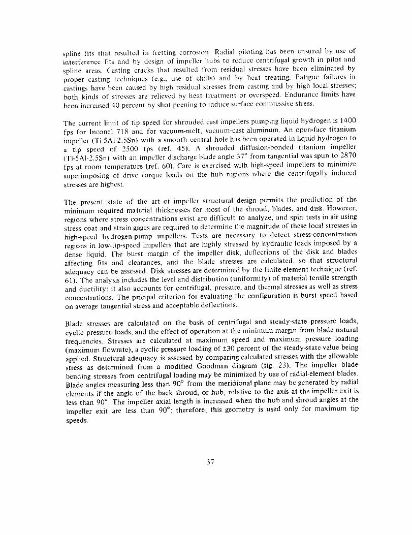
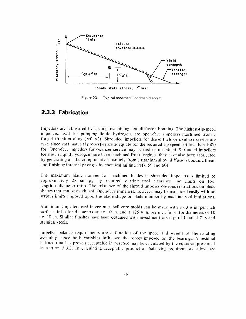
applied. Structural adequacy is assessed by comparing calculated stresses with the allowablestress as determined from a modified Goodman diagram (fig. 23). The impeller blade
bending stresses from centrifugal loading may be minimized by use of radial-element blades.
Blade angles measuring less than 90 ° from the meridional plane may be generated by radial
elements if the angle of the back shroud, or hub, relative to the axis at the impeller exit is
less than 90 ° . The impeller axial length is increased when the hub and shroud angles at the
impeller exit are less than 90°; therefore, this geometry is used only for maximum tip
speeds.
37
b _
,,a
I.
_, ndurance
limit
Fal lure
_'_L,. / strength(_ _ _'/_LI. //--Tensile
Steady-state stress. Gmean
Figure 23. - Typical modified Goodman diagram.
2.3.3 Fabrication
Impellers arc fabricated by casting, machining, and diffusion bonding. The highest-tip-speedimpellers, used for pumping liquid hydrogen, are open-face impellers machined from a
forged titanium alloy (ref. 62). Shrouded impellers for dense fuels or oxidizer service are
cast, since cast material properties are adequate for the required tip speeds of less than 1000
fps. Open-face impellers for oxidizer service may be cast or machined. Shrouded impellers
for use in liquid hydrogen have been machined from forgings; they have also been fabricated
by generating all tile components separately from a titanium alloy, diffusion bonding them,
and finishing internal passages by chemical milling (refs. 59 and 60).
Tile maximum blade number for machined blades in shrouded impellers is limited toapproximately 28 sin _32 by required cutting tool clearance and limits on tool
length-to-diameter ratio. The existence of the shroud imposes obvious restrictions on blade
shapes that can be machined. Open-face impellers, however, may be machined easily with no
serious limits imposed upon the blade shape or blade number by machine-tool limitations.
Aluminum impellers cast in ceramic-shell core molds can be made with a 63 /a in. per inchsurface finish for diameters up to 10 in. and a 125 /a in. per inch finish for diameters of 10
to 20 in. Similar finishes have been obtained with investment castings of Inconel 718 andstainless steels.
Impeller balance requirements are a function of the speed and weight of the rotating
assembly, since both variables influence the forces imposed on the bearings. A residual
balance that has proven acceptable in practice may be calculated by the equation presented
in section 3.3.3. In calculating acceptable production balancing requirements, allowance
38
must be made for manufacturing and assembly errors that result in offset of rotors fronl
true center. Nornmlity control and piloting influence the rotor rotating center after
assembly. Provisions for final balance after assembly can be used to minimize imbalance in
very-high-speed machines.
In the assembly of built-up rotors, the possibility of misassembly exists whenever a part can
be mounted in more than one position. Various practices are used to preclude the possibility
of misassembly. These usually take the form of minor modifications to the hardware that
prevent mating the parts when they are not in the correct position.
All the various components of a rotating assembly obviously must be designed for the same
direction of rotation, it is an established practice to coordinate design efforts and avoid
problems of mismatched direction of rotation by making a preliminary axonometric
projection of the assembly that shows clearly the direction of rotation. Copies are furnished
to all designers on the job.
High-speed impellers are proof tested by prespinning each part during the fabrication
process to provide partial quality assurance. Prespinning each impeller has additional
benefits in that local yielding occurs at areas of high strain concentration such as bolt holes,
splines, and keyways. This yielding produces favorable residual stresses that effectively
prestress the part and prevents the occurrence of yielding during operation.
2.3.4 Materials
Impeller materials that have been used successfully with rocket propellants are shown in
table II. Materials that are not listed as cast were forged. The materials are chemically
compatible with the pumped fluid, have satisfactory strength and ductility at the operating
temperatures, and can be used to fabricate impellers with existing technology.
2.4 HOUSING
The pump housing is the physical structure that forms the containing envelope for the
pump. It consists of the casing (the part of the pump that surrounds the impeller), the
diffusing system and volute for single-stage pumps, and the crossover system for multistage
pumps. The diffusing system may include vaned or vaneless diffusers upstream of the voluteand a conical diffuser or duffusers downstream of the volute. In addition, the housing
contains and mounts the bearings that support the rotating assembly and the seals that
prevent leakage of the pumped fluid. Consideration is given to both the mechanical and
hydraulic factors in selecting a particular housing configuration, because the housing not
39
Table II. - Materials Successfully Used for Impellers
Impellermaterial
Aluminum
A356 (cast)
A357 (cast)2014-T6
6061 -T6
7075-T73
7079
Steel
AM 350
304L (cast)304L
310
347 (cast)
lnconel 718 (cast)
"K" Monel
Ti-5AI-2.5Sn
LH 2, IRFNA,
CH4 N204
X
X
X X
X
XX
X
Pumped fluid
LOX LF2 FLOX RP- 1
X
X
X
X
X
Note:
X
XX
X
X
X X
X
X
X
X X
N 2H4 , UDMH,or 50/50mixture
X
X
X
X
X
X
X indicates that the material was used successfully with the fluid shown; absence of X means either that no
data on the use are available or that the material was incompatible with the fluid. Materials not shown ascast were forged.
i
only represents the major segment of pump weight but has a most significant effect upon
pump efficiency. It is commonly accepted that the housing determines the operating pointwhere the best efficiency occurs (refs. 63 and 64).
Housings have been successfully fabricated using two basic processes: casting in one or more
pieces, or welding together forged, formed, cast, or machined elements. Materials have
included cast aluminum alloys, cast stainless steels, and high-strength wrought aluminum
alloys and steels. Sometimes, separate liners are used to provide an inert material as an
interface with the impeller to achieve configuration flexibility or to simplify fabrication.
40
l)uffuservanescan bc integral or separate. Reinforcing bolts through diffuser or guide vanes
have provided structural aid.
Housing structures must be designed to sustain mounting loads as well as internal pressure
loads. External loads on parts such as the volute may be minimized by incorporating flexible
ducts that minimize bending loads.
2.4.1 Hydrodynamic Design
The hydrodynamic design of the housing components is based on a combination of
theoretical and empirical considerations. A systematic experimental background similar to
that for axial pump and compressor cascades is not available, because the greater geometric
and analytical complexity of the centrifugal pump makes the experimental task more
difficult and because to date there has been less emphasis on this approach.
2.4.1.1 CASING
Major considerations in the design of the casing involve the shape and smoothness of the
interior walls that form the flow path from the inlet to the diffiuser (fig. 1). The shape must
follow closely the exact contour of the impeller, particularly for an open-face impeller
where this wall contour establishes the size and uniformity of the tip clearance. The
roughness of the casing inner wall- due either to surface finish or to fasteners and
attachment points influences the radial pressure gradient and thereby the axial thrust
balance. Furthermore, increasing roughness of the wall increases the impeller disk friction
loss. Current practice is to achieve a surface finish of about 63 # in./in.: necessary fasteners
and attachment points are located as close as possible to the pump center line where the
impeller relative velocity and therefore fluid velocity - is at its lowest.
2.4.1.2 DIFFUSION SYSTEM
The pump diffusion systems of interest for both single and multistage pumps are thevaneless and vaned diffuser upstream of the volute and the conical diffuser downstream of
the volute. For multistage pumps, the diffusing system between stages may consist of a
vaned diffuser followed by an internal crossover passage with no volute, or a volute followed
by external crossover tubes.
2.4.1.2.1 Vaneless Diffuser
The gap between the impeller discharge and the vaned diffuser inlet or the volute tongue
(referred to as a vancless diffuser} acts as a mixing zone for the impeller blade wakes: this
41
mixing can significantly suppress pressure-perturbation effects (ref. 65). Figure 24 shows
this gap expressed as the ratio of diametral clearance to impeller diameter plotted against
impeller discharge flow angle. The available mixing length is approximately the radial
clearance divided by the sine of the impeller discharge flow angle. Current practice is to
maintain a constant ratio of mixing length to impeller diameter by increasing the spacing asthe impeller discharge flow angle increases.
,3
_g
"_-o .1
5 Io 15 20 25
Impeller discharge flow angle, deg
Figure 24. - Impeller-to-stator spacing as a function of
discharge flow angle.
As an example of the influence of this gap size, a gain of 1.8 percent in the efficiency of the
NERVA pump (at a specific speed of 980) was obtained by trimming the impeller and
thereby increasing the ratio of diametral clearance to impeller diameter from 0.03 to 0.06.
It should be noted that any increase in gap size above the minimum values necessary for
suppression of pressure perturbations (fig. 24) reduces efficiency and increases weight. In
addition, pressure losses in the vaneless diffuser increase as pump specific speed decreases;these pressure losses may be calculated by procedures presented in reference 66. The
required radial clearance may be reduced by design of the impeller to produce a minimumthickness of the boundary layer.
2.4.1.2.2 Vaned Diffuser
A vaned diffuser provides volute flow-matching over a wide flow range and also a lower
volute velocity that reduces the pressure differences caused by manufacturing variations.
42
Both the volute flow-matchingand reducedvolute velocity reduceimpellerradial loads.Vaneddiffusersarealsousedto obtain maximumpump efficiency.The reducedvolutevelocity resultsin a 3-percentincreasein pumpefficiencyat a specificspeedof 1200andgreaterimprovementas specificspeedsare decreased(ref. 4). However,vaneddiffusersdesigned for radial-vaned impellers in low-specific-speedpumps have exhibiteddiscontinuitiesin the head/capacitycurve at flow rates of 45 to 50 percent of the
best-efficiency operating point (fig. 13). Operation at or near this region of head
discontinuity (diffuser stall) usually is unstable and is avoided. The design-point efficiency
of pumps with vaned diffusers generally is higher and remains higher with decreasing flow,
but falls more rapidly with increasing flow than that for pumps with a vaneless volute.
Most investigators (refs. 63, 64, 67, and 68) agree that the diffuser throat area is the most
important parameter for determining a match with the impeller discharge flow. Figure 25
_ 1.0
.8
.5
t_
----------____>I I I I I I I I I I
5 6 8 10 15 20 30 40 50 60
Fluid flow Ingle leaving Impeller, deg
Figure 25. - Relative velocities in diffuser throat and at
impeller discharge as a function of fluid flow angle.
presents the ratio of diffuser throat velocity to impeller discharge velocity that may be usedto calculate the diffuser throat area. The diffuser inlet angle and shape also influence the
slope of the characteristic curves; however, systematic design information is not available.
The rate of diffusion described by the effective cone angle of the vaned diffuser strongly
influences the number of diffuser vanes required. Eckert and Schnell (ref. 66) present an
equation that relates the required number of circular arc diffuser vanes to the diffuser
equivalent cone angle 0, radius ratio R4/R3, discharge-to-inlet area ratio A4/A3 of the vaned
diffuser, and vane inlet angle /33. The results of calculations for several area ratios are
presented in figure 26; the equivalent cone angle used in the calculations was 8 °. A smallnumber of diffuser vanes minimizes blockage, and so each diffuser passage is fed by more
than one impeller passage (ref. 69).
43
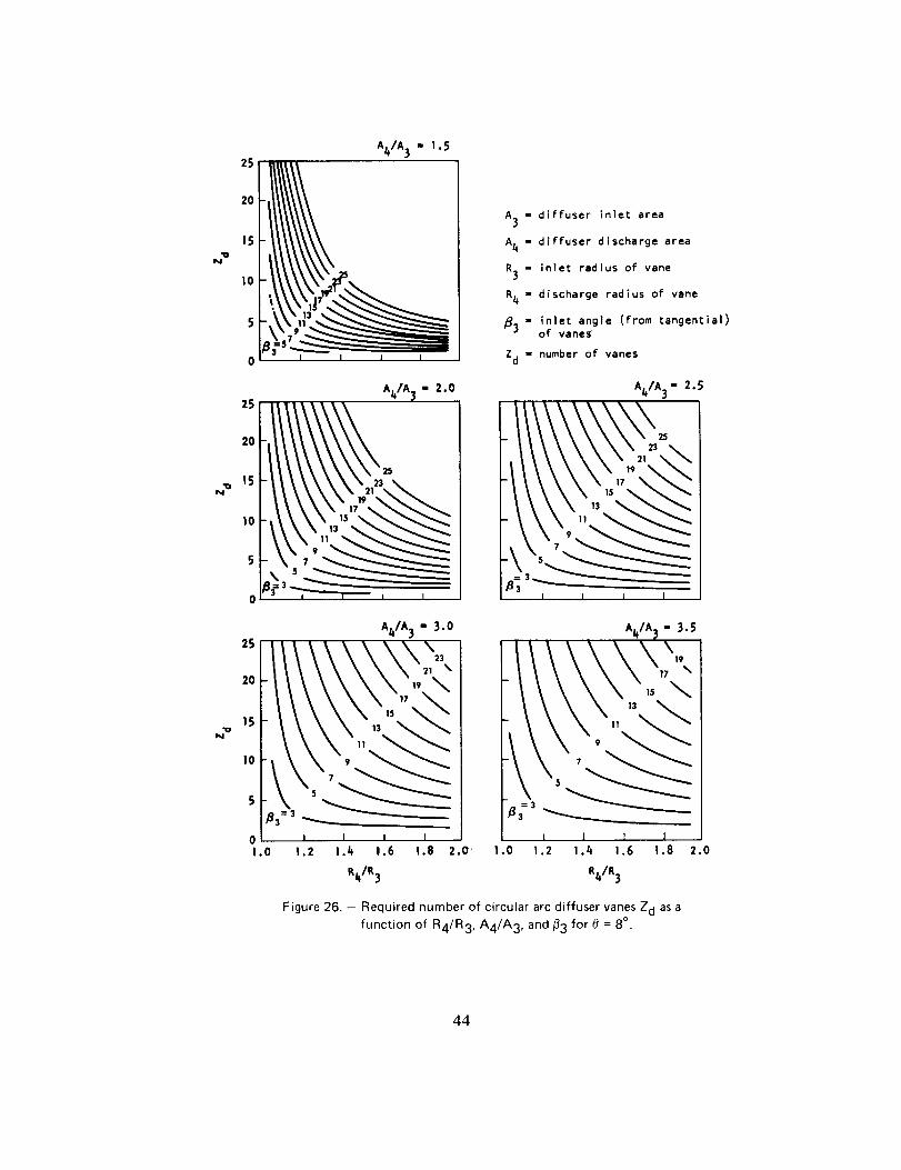
"oN
A4/A 3 - 1.525
2O
15
10
5
0
A3 = diffuser inlet area
A4 - diffuser discharge area
R3 m inlet radius of vane
R4 - discharge radius of vane
_3 " inlet angle (from tangential)of vane;
Zd m number of vanes
A4]A_I- 2.0 A4/A 3 - 2.5
3
, I I I I
"uN
25
2O
15
I0
A_/A 3 " 3.0
+83 = 3 ___
I I I I1.0 1.2 1.4 1.6 1.8 2.O +
Ai_/A _ " 3.5
I I I I.0 1.2 1.4 1.6 i.8 2.0
R41R 3 R41R3
Figure 26. - Required number of circular arc diffuser vanes Z d as a
function of R4/R3, A4/A3, and _3 for 8 = 8 °.
44
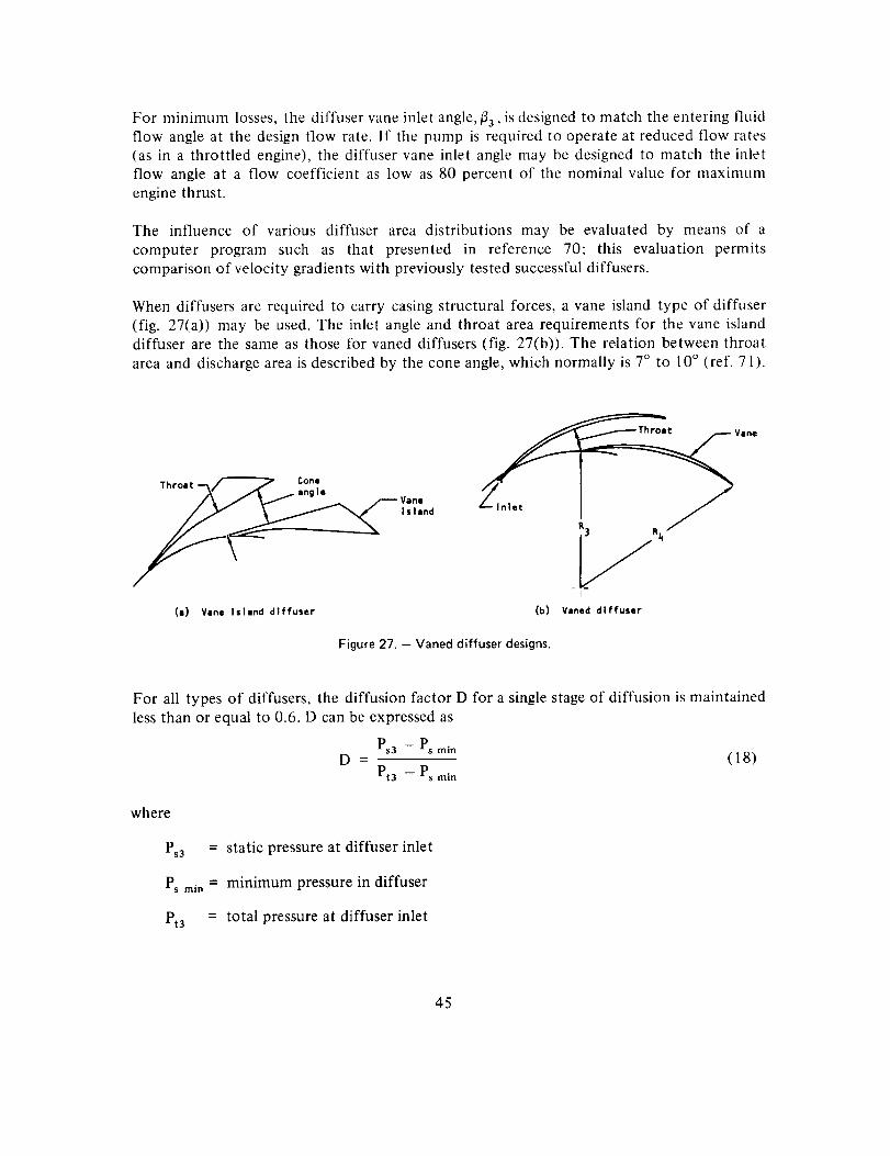
For minimum losses, the diffuser vane inlet angle, _33, is designed to match the entering fluidflow angle at the design flow rate. If the pump is required to operate at reduced flow rates
(as in a throttled engine), the diffuser vane inlet angle may be designed to match the inlet
flow angle at a flow coefficient as low as 80 percent of the nominal value for maxilnunl
engine thrust.
The influence of various diffuser area distributions may be evaluated by means of a
computer program such as that presented in reference 70; this evaluation permits
comparison of velocity gradients with previously tested successful diffusers.
When diffusers are required to carry casing structural forces, a vane island type of diffuser
(fig. 27(a)) may be used. The inlet angle and throat area requirements for the vane island
diffuser are the same as those for vaned diffusers (fig. 27(b)). The relation between throat
area and discharge area is described by the cone angle, which normally is 7° to 10 ° (ref. 71).
Vane
Island
(a} Vane Island diffuser
Vane
lnlet J
_3 Rb,
I
(b) Vaned diffuser
Figure 27. - Vaned diffuser designs.
For all types of diffusers, the diffusion factor D for a single stage of diffusion is maintained
less than or equal to 0.6. D can be expressed as
Ps3 - Ps min
D - (18)Pta - Ps rain
where
Ps3 = static pressure at diffuser inlet
Ps m_. = minimum pressure in diffuser
Pt3 = total pressure at diffuser inlet
45
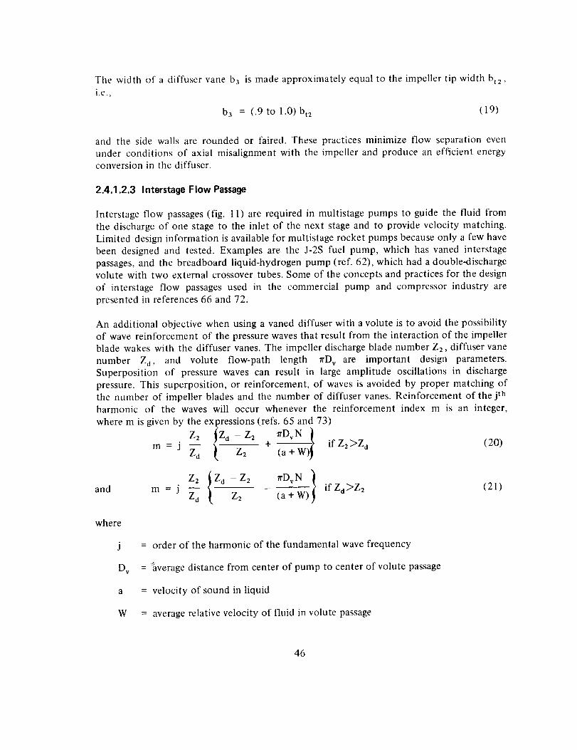
The width of a diffuservane b 3 is made approximately equal to the impeller tip width bt2,
i.e.,
b 3 = (.9 to 1.0) bt2 (1 9)
and the side walls are rounded or faired. These practices minimize flow separation even
under conditions of axial misalignment with the impeller and produce an efficient energyconversion in the diffuser.
2.4.1.2.3 Interstage Flow Passage
Interstage flow passages (fig. l l) are required in multistage pumps to guide the fluid from
the discharge of one stage to the inlet of the next stage and to provide velocity matching.
Limited design information is available for multistage rocket pumps because only a few have
been designed and tested. Examples are the J-2S fuel pump, which has vaned interstage
passages, and the breadboard liquid-hydrogen pump (ref. 62), which had a double-dischargevolute with two external crossover tubes. Some of the concepts and practices for the design
of interstage flow passages used in the commercial pump and compressor industry are
presented in references 66 and 72.
An additional objective when using a vaned diffuser with a volute is to avoid the possibility
of wave reinforcement of the pressure waves that result from the interaction of the impeller
blade wakes with the diffuser vanes. The impeller discharge blade number Z2, diffuser vane
number Z d, and volute flow-path length rrD v are important design parameters.
Superposition of pressure waves can result in large amplitude oscillations in discharge
pressure. This superposition, or reinforcement, of waves is avoided by proper matching ofthe number of impeller blades and the number of diffuser vanes. Reinforcement of the jthharmonic of the waves will occur whenever the reinforcement index m is an integer,
where m is given by the expressions (refs. 65 and 73)
Z2 !Z a - Z2 rrDvN t
m = j _ _, Z_ + (a+W)} ifZ2>Z d(20)
z2 ovNIand m = j _d Z2 (a+W) ifZd]>Z2 (21)
where
j = order of the harmonic of the fundamental wave frequency
Dv = _'hverage distance from center of pump to center of volute passage
a = velocity of sound in liquid
W = average relative velocity of fluid in volute passage
46
2.4.1.3 VOLUTE
The object of volute design is to provide a distribution of cross-sectional area with respect to
wrap angle that will yield a constant impeller discharge static pressure at the design point of
the pump; the radial load on the shaft and the impeller vibrations are thereby minimized.
An asymmetric volute cross section is preferred because it produces a single vortex thut is
stable and that improves the efficiency of the conical diffuser at the exit (refs. 66 and 71).
The conical diffuser at the volute exit will operate efficiently when the included angle for
circular cross sections is between 7° and 9°; for square cross sections, 6°; and for two
parallel walls, 11 °.
The inlet angle of the volute tongue is designed for zero incidence angle at the design flow in
order to reduce the losses associated with the volute, to minimize local pressure difference_,
and to reduce the amplitude of the pressure oscillations in the pump discharge. If a vaned
diffuser precedes the volute, the transition from the vaned diffuser to the volute tongue
must be designed to avoid an interaction that would lead to an unstable (e.g., bi-stable)
pump head-versus-flow characteristic. Stable flow is achieved by fairing one diffuser wine
into the volute tongue or by leaving a large clearance between the vane discharge and the
tongue.
2.4.1.3.1 Cross-Sectional Area
Two methods are in use for sizing the volute cross-sectional area: constant moment of
momentum, and constant mean velocity.
Constant moment of momentum. - The fluid tangential velocity is assumed to be inversely
proportional to the radius. After the volute shape has been established, the volvte
cross-sectional area satisfying the given flow requirement is determined at each
circumferential station. The constant-moment-of-momentum method was applied to the
design of Titan ! and Titan II pump housings; corrected for friction losses (ref. 74), the
method was used in the design of the J-2S Mark 29 fuel pump, which experienced very light
radial bearing loads.
Constant mean velocity.- The velocity is assumed to be constant, and therefore the
cross-sectional area is increased proportionally as the central volute wrap angle increases.
The method was developed as a simplification in volute design.
Although there are only minor differences in pump efficiency between the two methods
(ref. 64), the unsymmetrical pressure (with its associated radial hydraulic forces upon the
impeller) around the volute passage has been found to be higher in designs based on the
constant-mean-velocity method (ref. 63).
47
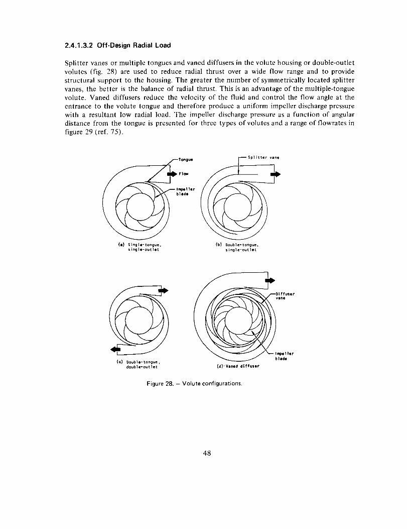
2.4.1.3.2 Off-Design Radial Load
Splitter vanes or multiple tongues and vaned diffusers in the volute housing or double-outlet
volutes (fig. 28) are used to reduce radial thrust over a wide flow range and to provide
structural support to the housing. The greater the number of symmetrically located splitter
vanes, the better is the balance of radial thrust. This is an advantage of the multiple-tonguevolute. Vaned diffusers reduce the velocity of the fluid and control the flow angle at the
entrance to the volute tongue and therefore produce a uniform impeller discharge pressure
with a resultant low radial load. The impeller discharge pressure as a function of angular
distance from the tongue is presented for three types of volutes and a range of flowrates in
figure 29 (ref. 75).
(i) Single-tongue,single-outlet
Splitter vane
((b) Oouble-tongue,
single-outlet
(c) Double-tongue,double-outlet
f
/ __D|ffuser
vane
l_ellerblade
(d)" Vined diffuser
Figure 28. - Volute configurations.
48
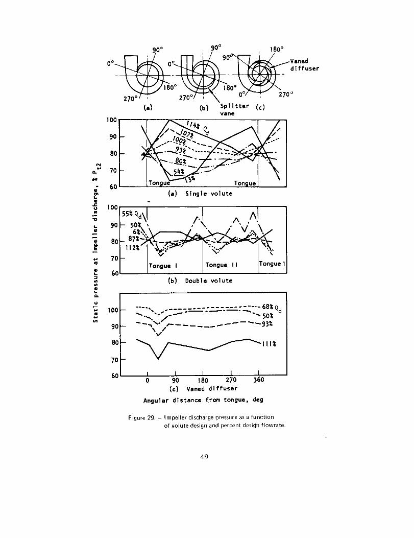
4.ao.
i.
gle-
Uvl
m
L
4.a
!.
U_
La.
gm4J
t4.l
90° 90° ! 80°
_ ___ diffuser
zTo ,-- z70°7-_'\ o°_--_, zToo(a) (b) Splitter (c)
vane
,oo| l '"_Q_F
70
60(a) Single volute
,0/ IT°''°-' I_°_u''' IT°n_u"(b) Double volute
100
90
80
7O
60
.... . . __................ 68_ Qd
_ --,¢'--/_ ...... ---- "--93_\ /
I I I I I0 90 180 270 360
(c) Vaned diffuser
Angular distance from tongue, deg
Figure 29. - impeller discharge pressure as a function
of volute design and percent desi_n flowrate.
49
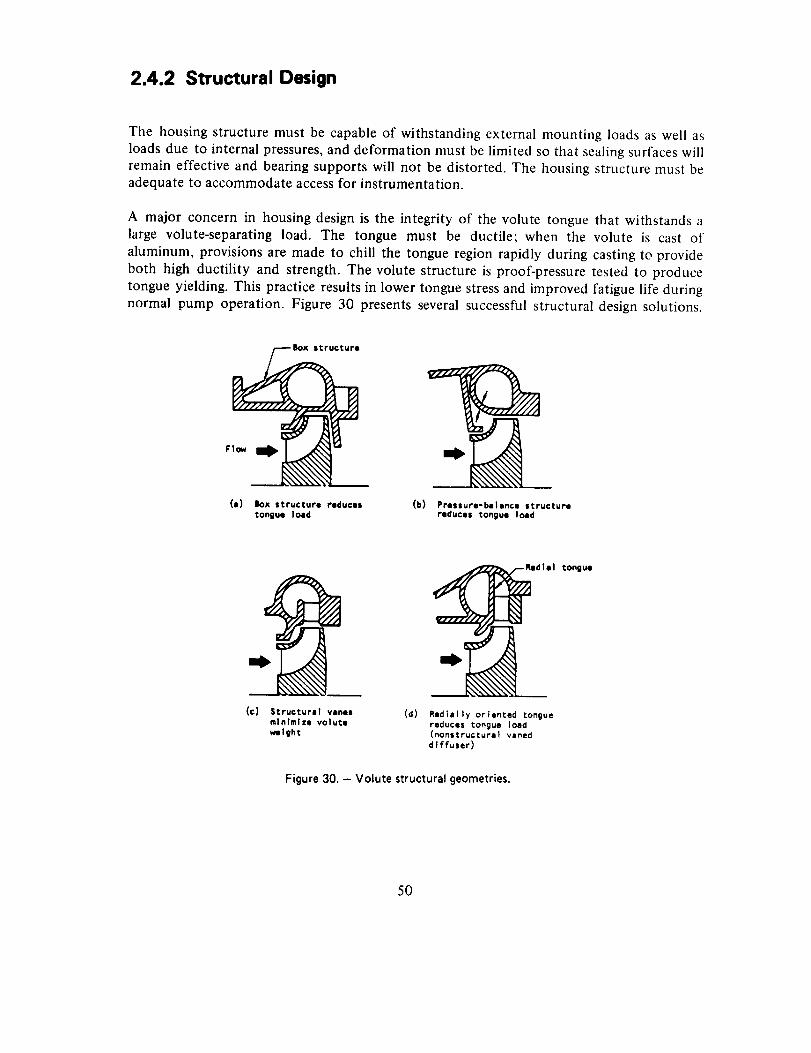
2.4.2 Structural Design
The housing structure must be capable of withstanding external mounting loads as well as
loads due to internal pressures, and deformation must be limited so that sealing surfaces will
remain effective and bearing supports will not be distorted. The housing structure must beadequate to accommodate access for instrumentation.
A major concern in housing design is the integrity of the volute tongue that withstands a
large volute-separating load. The tongue must be ductile; when the volute is cast of
aluminum, provisions are made to chill the tongue region rapidly during casting tc provide
both high ductility and strength. The volute structure is proof-pressure tested to produce
tongue yielding. This practice results in lower tongue stress and improved fatigue life during
normal pump operation. Figure 30 presents several successful structural design solutions.
gox structure
Flo_
(e) Box structure reduces
tongue load
(b) Pressure-balance structure
reduces tongue load
(c) Structural vanes
minimize volute
weight
(d) Radially oriented tongue
reduces tongue load(nonstructurel vaned
diffuser)
Figure30. - Volute structuralgeometries.
tongue
50
Figure 30(a) utilizes a box structure to minimize the volute tongue deformation. The design
in figure 30(b) pressure balances much of the volute to minimize tongue deformation. In
figure 30(c), structural diffuser vanes support volute separating forces and thereby minimizeweight. The design of figure 30(d) utilizes a long radially oriented tongue in conjunction
with nonstructural diffuser vanes in a folded volute; the long radial tongue is loaded in
bending rather than in tension so that the loads are minimized.
in order to minimize external forces upon the pump housing, the inlet and discharge ducting
may be connected to the engine by flexible bellows. Another method for keeping external
loads low is to utilize the discharge duct as part of the mounting structure to the engine in
conjunction with hinged mounting points on the housing. This design requires the use of
only a low-pressure bellows at the pump inlet and so is adaptable to high pump-discharge
pressures. For minimum volute separating forces, a circular cross section is used. Housingstresses and deflection may be calculated by procedures presented in references 61 and 76.
Tile steady state and dynamic stresses calculated for the pump housing are evaluated by
means of a modified Goodman diagram (fig. 23) in order to establish the capability of the
design to meet the required life. Safety factors are applied to compensate for uncertainties
in material properties and analytical techniques. The values of the safety factors vary with
the type of material control, quality control, and structural development program and with
the expected application. Current practices in the use of structural design safety factors aresummarized in table III.
2.4.3 Mechanical Design
The mechanical design of the pump housing must satisfy the hydrodynamic requirements
and in addition provide reliable structure, leak-free joints and static seals, reliable fasteners
and attachments, materials compatible with the propellants, and fabrication feasibility.
Provision for anticipated special instrumentation is made during the design phase to ensure
access and structural reliability.
2.4.3.1 JOINTS AND STATIC SEALS
Joints serve to connect housing components and to carry loads. A joint also may be required
to prevent a leak from a region of high pressure to one of lower pressure internally or to the
environment surrounding the pump.
Bolt and stud-nut and clamp-type flange configurations have been used successfully. For
high-pressure pumps (>1000 psi), bolts or studs with nuts to connect mating flange jointshave been used. Face-to-face contact is preferred in order to control contact loads, minimize
relative motion and so avoid fretting, and provide reliable dimensional control. The joint
51
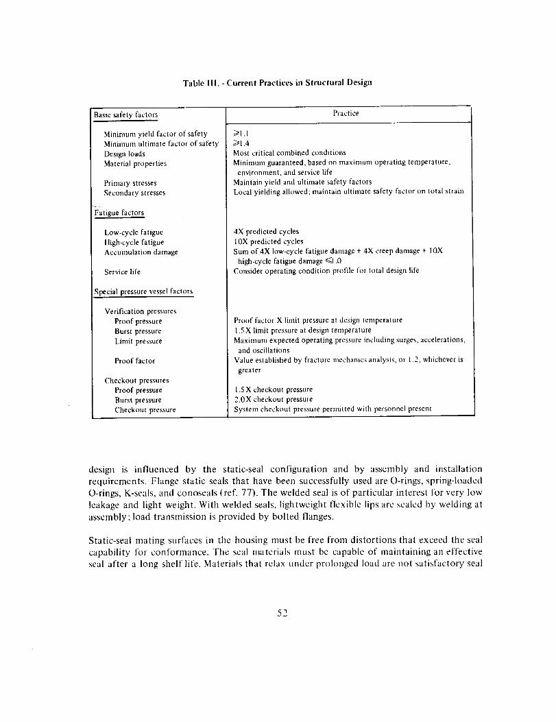
Tablelll. - Current Practices in Structural Design
Basic safety factors
Minimum yield factor of safety
Minimum ultimate factor of safety
Design loads
Material properties
Primary stresses
Secondary stresses
Fatigue factors
Low-cycle fatigue
High-cycle fatigue
Accumulation damage
Service life
Special pressure vessel factors
Verification pressures
Proof pressure
Burst pressure
Limit pressure
Proof factor
Checkout pressures
Proof pressure
Burst pressure
Checkout pressure
Practice
/>1.1
>/1.4
Most critical combined conditions
Minimum guaranteed, based on maximum operating tetnperature,
environment, and service life
Maintain yield and ultimate safety factors
Local yielding allowed; maintain ultimate safety factor on total strain
4X predicted cycles
10X predicted cycles
Sum of 4X low-cycle fatigue damage + 4X creep damage + 10X
high-cycle fatigue damage El .0
Consider operating condition profile for total design life
Proof factor X limit pressure at design temperature
1.5 X limit pressure at design temperature
Maximum expected operating pressure including surges, accelerations,and oscillations
Value established by fracture mechanics analysis, or 1.2, whichever is
greater
1.5 X checkout pressure
2.0X checkout pressure
System checkout pressure permitted with personnel present
design is influenced by the static-seal configuration and by assembly and installation
requirements. Flange static seals that have been successfully used are O-rings, spring-loaded
O-rings, K-seals, and conoseals (ref. 77). The welded seal is of particular interest for very low
leakage and light weight. With welded seals, lightweight flexible lips are sealed by welding at
assembly; load transmission is provided by bolted flanges.
Static-seal mating surfaces in the housing must be free from distortions that exceed the seal
capability for conformance. The seal materials must be capable of maintaining an effective
seal after a long shelf life. Materials that relax under prolonged load are not satisfactory seal
52
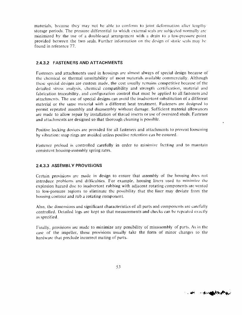
materials, because they may not be able to conform to joint deformation after lengthy
storage periods. The pressure differential to which external seals are subjected normally tire
minimized by tile use of a double-seal arrangenlent with a drain to a low-pressure point
provided between the two seals. Further information on tile design of static seals may be
found in reference 77.
2.4.3.2 FASTENERS AND ATTACHMENTS
Fasteners and attachments used in housings are almost always of special design because of
the chemical or thermal unsuitability of most materials available commercially. Although
these special designs are custom made, the cost usually remains competitive because of the
detailed stress analysis, chemical compatibility and strength certification, material and
fabrication traceability, and configuration control that nmst be applied to all fasteners and
attachments. The use of special designs can avoid the inadvertent substitution of a different
material or the same material with a different heat treatment. Fasteners are designed to
permit repeated assembly and disassembly without damage. Sufficient material allowances
are made to allow repair by installation of thread inserts or use of oversized studs. Fastener
and attachments are designed so that thorough cleaning is possible.
Positive locking devices are provided for all fasteners and attachments to prevent loosening
by vibration;snap rings are avoided unless positive retention can be ensured.
Fastener preload is controlled carefully in order to minimize fretting and to maintain
consistent housing-assembly spring rates.
2.4.3.3 ASSEMBLY PROVISIONS
Certain provisions are made in design to ensure that assembly of the housing does not
introduce problems and difficulties. For example, housing liners tlsed to minilnize the
explosion hazard due to inadvertent rubbing with adjacent rotating components are vented
to low-pressure regions to eliminate the possibility that the liner may deviate from the
housing contour and rub a rotating component.
Also, the dimensions and significant characteristics of all parts and components are carefully
controlled. Detailed logs are kept so that measurements and checks can be repeated exactly
as specified.
Finally, provisions are made to minimize any possibility of misassembly of parts. As in tile
case of tile impeller, these provisions usually take the form of minor changes to tile
hardware that preclude incorrect mating of parts.
53
.
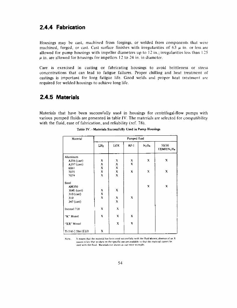
2.4.4 Fabrication
Housings may be cast, machined from forgings, or welded from components that weremachined, forged, or cast. Cast surface finishes with irregularities of 63 /_ in. or less are
allowed for pump housings with impeller diameters up to 12 in.; irregularities less than 125
in. are allowed for housings for impellers 12 to 24 in. in diameter.
Care is exercised in casting or fabricating housings to avoid brittleness or stress
concentrations that can lead to fatigue failures. Proper chilling and heat treatment of
castings is important for long fatigue life. Good welds and proper heat treatment are
required for welded housings to achieve long life.
2.4.5 Materials
Materials that have been successfully used in housings for centrifugal-flow pumps with
various pumped fluids are presented in table IV. The materials are selected for compatibility
with the fluid, ease of fabrication, and reliability (ref. 78).
Table IV. - Materials Successfully Used in Pump Housings
Material Pumped fluid
LH2 LOX RP-I
Aluminum
A356 (cast) X X X
A357 (cast) X X X6061 X X
7075 X X X
7079 X X
Steel
AM350
304L (cast)
310 (cast)
310
347 (cast)
Inconel 718
"K" Monel
"KR" Monel
X X
X
X X X
X
X X
X X X
X X
Ti-SAI-2.5Sn (ELI) X
N204 50/50
UDMH/N2H4
X X
X X
X X
Note: X means that the material has been used successfully with the fluid Ihown; absence of an X
means either that no data on the specific use are available or that the material cannot be
used with the fluid Materials not shown as cast were wrought
54
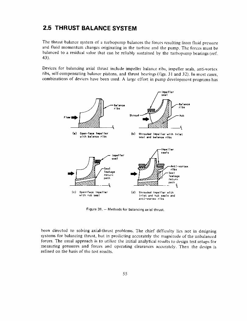
2.5 THRUST BALANCE SYSTEM
The thrust balance system of a turbopump balances the forces resulting from fluid pressure
and fluid momentum changes originating in the turbine and the pump. The forces must be
balanced to a residual value that can be reliably sustained by the turbopump bearings (ref.43).
Devices for balancing axial thrust include impeller balance ribs, impeller seals, anti-vortex
ribs, self-compensating balance pistons, and thrust bearings (figs. 31 and 32). In most cases,
combinations of devices have been used. A large effort in pump development programs has
#,/'_Belance
""
(e) 0pen-face Impellerwith balance ribs
Impel ler
seal/rl;;
(b) Shrouded Impeller with Inlet
sea] and balance ribs
(c) 0penmface impellerwith hub seal
--Impel lar
Inl__ seal_ rAnt I-vortex
_'/ rlbs
_I/--._ea'IW ,e,_,,o_ return
path
(d) Shrouded impeller with
inlet and hub seals andanti-vortex ribs
Figure 31. - Methods for balancing axial thrust.
been directed to solving axial-thrust problems. The chief difficulty lies not in designingsystems for balancing thrust, but in predicting accurately the magnitude of the unbalanced
forces. The usual approach is to utilize the initial analytical results to design test setups for
measuring pressures and forces and operating clearances accurately. Then the design isrefined on the basis of the test results.
55
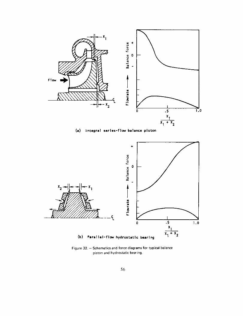
' Xl
-"It"- x2
(a) integral
OJUt-
O
UClID
ttU
lU
÷
0
0 .5 I .0
x1
X 1 +12
series-flow balance piston
÷
qt_
U,.
• I0 .5 I .0
x i
(b) Para|lel-flow hydrostatic bearingX1 + X2
Figure 32. - Schematics and force diagrams for typical balance
piston and hydrostatic bearing.
56
2.5.1 Unbalanced Forces
Turbine forces are balanced by the pump axial-thrust system in state-of-the-art turbopunlps.
Procedures for calculating turbine pressures and axial forces are presented in reference 42.
Model turbine tests are used to measure internal pressures so that thrust balance forces may
be more accurately estimated. Since nozzle spouting velocities are very high, flow steps in
the stream can produce large axial forces on rotors. Rotor/stator alignment and the shape ofthe turbine rotor downstream of the nozzle are controlled to maintain these forces within
the capability of the hardware.
In the pump, pressure gradients occur on the smooth nonpumping impeller hub and shroud
surfaces as well as on the open faces of impellers. The pressure gradients on the nonpumping
surfaces caused by viscous forces may be calculated by the procedures presented in
reference 79. The pressures on the face of an open impeller may be calculated by procedures
presented in references 53, 54, and 80.
2.5.2 Methods of Thrust Balance
2.5.2.1 IMPELLER WEAR RINGS
Impeller wear rings, also called impeller seals, are used on the front shroud and hub of
shrouded impellers for control of axial thrust (figs. 31(b) and (d)). The area at a diametersmaller than the hub wear ring is held at a pressure slightly above the impeller inlet value by
directing the leakage flow from the wear ring to the impeller inlet through holes in the
impeller or through external passages. The relative diameters of the two wear rings are sized
to produce the required balance force. The J-2 oxidizer pump, which is thrust balanced byuse of wear rings, utilizes anti-vortex ribs at a diameter smaller than the hub wear ring to
influence the radial pressure gradient in that area. Control of the pressure gradient in that
region by trimming the ribs permits adjusting the axial thrust of the impeller without
changing the diameters of the impeller wear rings.
The fuel turbopump in the F-I engine had lead-plated impeller wear rings. When the wear
ring rubbed during operation, the relatively soft lead "rolled up" and caused wear on the
back disk of the impeller and shroud. The problem was minimized by improving the bond ofthe lead to the base metal and by enlarging the clearances to reduce the degree of rubbing.
2.5.2.2 IMPELLER BALANCE RIBS
Impeller balance ribs are blades located on the back of the impeller hub (fig. 31(a)). Theyform a low- or zero-flow impeller that provides a large pressure gradient where they are
57
located.The rib pumpingactionreducesthe pressureat thesmallerdiameterto counteractthe low pressureat the impellerinlet. Holesmaybeprovidedthroughtheimpellerinto theinsidediameterregionof the balanceribs to vent that regionstaticallyand to provideapositivecoolant flow into thebalanceribsto preventcavitationcausedby fluid heatingthatresultsfrom the pumpingwork of the balancerib. Balanceribshavebeenusedon manysuccessfulturbopumps:however,usuallymoredevelopmentwork is requiredto obtainaconfigurationthat isaseffectiveaswearrings.
Thegear-drivenTitan pumpsutilizedopen-faceimpellerswith balanceribson theimpellerhub that reducedthe axial force to a valuethat couldbesustainedby asplit-inner-raceballbearing.TheF-1turbopumphadshroudedimpellers;for controlof axial thrust,theoxidizerpump impeller incorporatedan inlet wear ring and balanceribs, while the fuel pumpimpellerincorporatedinlet andhub wearrings.Thepumpforcesbalancedthe direct-driveturbine forcessuchthat tandemsplit-inner-raceball bearingscouldsustainthe unbalancedaxialforce.
2.5.2.3 BALANCE PISTONS AND HYDROSTATIC BEARINGS
When pumps operate at very high speeds, ball bearings are not capable of sustaining the
normal operating unbalanced axial forces. For these applications, balance pistons and
hydrostatic bearings are used. The two types that have been used for rocket engine
centrifugal pumps are the series-flow balance piston integral with the impeller (fig. 32(a))
and the separate parallel-flow hydrostatic bearing (ref. 45 and fig. 32(b)). Both types are
self-compensating bearings that seek an operating clearance such that the bearings that
radially locate the rotor operate with an acceptable axial force. These bearings are designed
to operate with a sufficient effective spring rate to avoid axial resonances of the rotatingassembly. The design of balance pistons and hydrostatic bearings usually is based onprocedures like those presented in reference 81.
The J-2S fuel pump incorporated a series-flow balance piston integral with the hub of the
second-stage impeller; this piston reduced the axial load to values that could be sustained by
ball bearings that were axially located by springs. The ball bearings positioned the rotatingassembly and sustained the spring-limited axial forces until pump pressures increased to
values allowing the balance piston to sustain the axial loads. The first stage, anintegral-inducer mixed-flow impeller, provided the axial force to balance the turbine force.
The balance piston used a rub ring of fiberglas-reinforced Teflon to minimize possible galling
of the orifices. The material delaminated, and the orifices opened up. The problem was
solved by using lead-filled porous bronze for the rub rings. The J-2 axial fuel pump initially
used carbon rub rings; the rings cracked, causing the orifices to open up. The problem alsowas solved by use of lead-filled porous bronze rub rings.
58
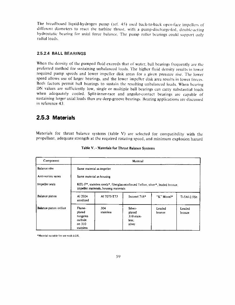
The breadboard liquid-hydrogen pump (ref. 45) used back-to-back open-face impellers of
different diameters to react the turbine thrust, with a pump-discharge-fed, double-acting
hydrostatic bearing for axial force balance. The pump roller bearings could support only
radial loads.
2.5.2.4 BALL BEARINGS
When the density of the pumped fluid exceeds that of water, ball bearings frequently are the
preferred method for sustaining unbalanced loads. The higher fluid density results in lower
required pump speeds and lower impeller disk areas for a given pressure rise. The lower
speed allows use of larger bearings, and the lower impeller disk area results in lower forces.
Both factors permit ball bearings to sustain the resulting unbalanced loads. When bearing
DN values are sufficiently low, single or multiple ball bearings can carry substantial loads
when adequately cooled. Split-inner-race and angular-contact bearings are capable of
sustaining larger axial loads than are deep-groove bearings. Bearing applications are discussed
in reference 43.
2.5.3 Materials
Materials for thrust balance systems (table V) are selected for compatibility with the
propellant, adequate strength at the required rotating speed, and minimum explosion hazard
Table V. - Materials for Thrust Balance Systems
Component Material
Balance ribs
Anti-vortex vanes
Impeller seals
Balance piston
Balance-piston orifice
Same material as impeller
Same material as housing
KEL-F*, stainless steels*, fiberglas-reinforced Teflon, silver*, leaded bronze,
impeller materials, housing materials
AI 2024 AI 7075-T73 lnconel 718" "K" Monel* Ti-5AI-2.5Snanodized
304 Leaded Leaded
stainless bronze bronze
Flame-
plated
tungstencarbide
on 310
stainless
Silver-
plated310 stain.
less;silver
*Material suitable for use with LOX.
59
in the event of an inadvertent rub. Plastic materials such as Kel-F, Teflon, and fluorinated
polyvinyl chloride resist burning if rubbed on the impeller in liquid-oxygen pumps and
therefore are safe stationary sealing materials when the seal pressure differential is not
excessive. The same materials are also satisfactory in liquid-hydrogen pump service.
Materials for the balance-piston orifice are selected to resist galling if rubbed against balance
piston rotor or impeller materials. To date, balance piston experience has been almost solely
limited to hydrogen pumps. Future oxygen-pumps with balance pistons must limit orifice
materials to those that can be LOX-cleaned, resist explosion or ignition upon impact, andare chemically and physically stable in liquid oxygen.
60
3. DESIGN CRITERIA and
Recommended Practices
3.1 CONFIGURATION SELECTION
The pump system shall be based on the itzteractions and tradeofJ_ of equivalent
perjbrmance (efficiency, weight, aim size), ef/brt to achieve required reliability.
apzd operational flexibility.
It is recommended that system tradeoff factors be evaluated as discussed in reference 1.
Tradeoff of performance factors should result in maximum engine specific impulse for the
required vehicle missions.
Select a centrifugal pump when a ratio of maximum-to-minimum stable specific speed N s
greater than 1.2 is required. An N_-vs-D s diagram containing representative data, as
presented in figure 3, should be used for preliminary selection activities.
Evaluate the parameters presented in figure 2 to ensure that mechanical and fluid-mechanicslimitations are observed.
Examine pump configurations critically to ensure that the manufacturing process, the
prescribed precision, and resulting costs are justified. Use tolerances, surface finishes, and
configurations that result in minimum manufacturing costs when the resulting performance
and weight meet the rocket engine requirements.
3.2 PUMP PERFORMANCE
The pump design point shah satisfy the required engine operating range and
provide the desired performance characteristics.
The design point should be selected on the basis of (1) the required stall margin under
starting, throttling, or other excursions, and (2) the desired shape of the headrise and
efficiency curves, including the stall or surge point. The number of stages should be the
minimum that can supply the required pressure and efficiency.
The pump design specification should include the following information (the primary source
of the information is indicated in the parentheses):
• Nominal design point requirements and tolerances imposed by the engine (Mission
Studies)
61
Extreme off-design flowrate, headrise, and net positive suction pressure
requirements including tolerances for component performance predictions andtolerances imposed by the engine (Engine Computer Model)
• Bearing, seals, and balance-piston flow (Preliminary Design Analysis)
• Future upgrading requirements (Mission Studies)
• Flight vehicle and static-test operating environment (Mission and DevelopmentTest Requirements)
• Handling and flight "g" loads (Mission and Development Test Requirements)
• Pump attitudes under static and flight conditions (Mission and Development TestRequirements)
Duty-cycle definitions including nominal, minimum, and maximum operatingduration; start transient, shutdown transient, and restart conditions; and
chilldown requirements (Mission and Development Test Requirements)
• Pump test and calibration requirements (Mission and Development TestRequirements)
• Design safety factors (Mission and Development Test Requirements)
• Instrumentation requirements (Mission and Development Test Requirements)
• Tradeoff parameters (i.e., change in the engine specific impulse per point of
efficiency, per pound of pump weight, and per inch of length) (Mission Studies)
• Reliability and safety requirements (Mission and Development TestRequirements)
It is recommended that the items listed above be surveyed at the outset of the design effort
to ensure that the information is available or will be forthcoming from the primary sourcesindicated. It is recommended also that these items be kept current and consistent with the
engine and turbopump requirements. In addition, the adequacy of the design should becontinuously assessed against these requirements.
3.2.1 Speed
The pump speed shall maximize pump <l'f)ciency within the limits ofItydr(_dy_mmic and structural constraints.
2
Optimize specific speed while observing other limits such as critical speed, suction specific
speed, required presstire rise and flowrate, and other limits previously discussed. Consult
figures 2, 3, 5, and 9, and observe tile guidelines presented below.
3.2.1.1 CRITICAL SPEED
The pump shall not operate continuously at a critical speed.
It is recommended that preliminary critical-speed studies be made to ensure that the
selected pump speed is at least 20 percent removed from any calculated critical speed.Reference 32 should be constilted for more precise information. Observe the analyticalprocedures and practices reported in reference 28.
Critical-speed calculations should consider bearing and bearing-support stifflaess inchiding
nonlinearities; rotor imbalance forcing functions; shear deformation; gyroscopic effects; and
viscous or Coulomb damping as well as bearing dynamic loads and shaft deflection
amplitudes in regions where control of critical clearances is required (refs. 2, 6, and 28).
3.2.1.2 SUCTION SPECIFIC SPEED
The design pump speed shall not reach the level at which head loss due tocavitation occurs.
For a pump with an integral inducer, maximum suction specific speed of 40 000 for the
inducer is recommended. Without an integral inducer, limit the S_ value to 12 000. Use alow-speed turbopump (boost pump) to increase pump inlet pressure when the available inlet
pressure is too low to permit reaching the speed required for efficiency and light weight.
In order to provide for manufacturing variations and for instrumentation errors, the pumpinlet NPSH should not be less than 3C2m i/2g for low-vapor-pressure fluids such as water and
RP-1, 2.3c 2 ,1 i/2g for fluids such as LOX and LF2, and 1.3c z m I/2g for liquid hydrogen.
Observe the limits on suction specific speed prescribed in reference 33 and in figure 4.
3.2.1.3 TURBINE LIMITS
The design pump speed shall not exceed the speed at which turbine stressesbecome excessil,e.
63
Observethe turbinespeed-limitingfactorspresentedin reference42 to ensurethat turbinestresslimits arenot exceededat thedesignpumpspeedandpower.
3.2.1.4 BEARING AND SEAL LIMITS
The pump design speed shall not exceed the speed limits for the bearings andseals.
Observe the bearing speed limits presented in reference 43 for the radial and axial loadsimposed on the bearing by rotor dynamics and fluid forces.
Observe the seal speed and pressure limits presented in reference 44. Noncontacting seals arerecommended when rubbing seals cannot satisfy speed and life requirements.
3.2.2 Efficiency
3.2.2.1 PUMP SIZE AND PUMPED FLUID
The values for pump efficieno, shall account for the effect of pump size andpumped fluid.
It is recommended that figure 6 be used for preliminary estimates of the influence of size onpump efficiency.
When a scaled-model pump or substitude fluids are used to obtain design data, the effects ofdifferences in Reynolds number, relative roughness, and relative clearances should be taken
into account. Observe Schlichting's formula for admissible roughness (eq. (11)).
The influence of increased seal clearances or impeller blade clearances required by oxidizer
pumps should be evaluated when comparing performances of similar pump designs. The
influence of fluid compressibility and internal leakage on efficiency of liquid-hydrogen
pumps should be evaluated with the use of fluid enthalpy and entropy as a function ofpressure and temperature.
3.2.2.2 GEOMETRY
Vahtes for pump efficieno, shall account for the effects of (1) the geometry
required to attain high suction specific speed and (2) the geometry of thediffusing system.
64
The efficiencyvariationdue to differencesin suctionspecificspeedmaybecalculatedfromthedatam figure9, whichpresentstheefficiencychangeasafunctionof thespecific-speedparameter.Figure5 is used for a preliminary calculation of the impeller inlet diameter.
Tile information presented in figure 6 and in reference 4 can be used to estimate the
influence of volutes and conical diffusers, vaned diffusers, and vaneless diffllsers on pump
efficiency.
3.2.2.3 STAGING
Values of pump efficiency shall account for the effects of staging.
Design for the minimum number of stages that (1) can supply the minimum efficiency
compatible with the engine system requirements and (2) will result in a pump that does not
exceed the impeller tip speed limits in any stage.
Vaned diffusers with internal crossover passages (fig. 1 l(b)) should be used for minimum
envelope and maximum efficiency. The external-diffusing-passage type may be used to take
advantage of its simpler geometry when the larger envelope and lower effiency are
acceptable.
3.2.3 Flow Range
3.2.3.1 HEAD-VS-FLOW CHARACTERISTIC
The pump head-vs-flow characteristic shall provide the flow range required by the
engine system.
The head-vs-flow characteristic of the pump should have a negative slope with respect to
head-vs-flow characteristic of the engine liquid flow system at all flowrates. The engine
liquid flow system may be considered as extending from the pump discharge to the
thrust-chamber injector discharge.
To provide rising head to the lowest possible flowrate, when the impeller discharges into avaned diffuser, the pump head coefficient should be equal to or less than 0.5.
3.2.3.2 IMPELLER BLADE NUMBER
The impeller blade mtmber shall produce the required flow range.
65
The impellerinlet bladenumbershouldbesmallenoughthat the impellerinlet freeareaismore than80 percentof the inlet annulararea.Theimpellerdischargebladenumbershouldbesufficient to providethe designheadcoefficientasshownby figure16.Referto section3.3for furtherconsiderationsaffectingbladenumber.
3.3 IMPELLER
3.3.1 Hydrodynamic Design
3.3.1.1 DIAMETER RATIO
The ratio of the impeller inlet tip diameter to discharge tip diameter shallmaximize efficiency consistent with the required suction performance.
The value for 6 should be established from the guides presented in figure 5. The requiredinlet diameter should be calculated by use of the suction performance informationpresented in figure 4 supplemented by the guidelines in reference 33.
3.3.1.2 HEAD AND FLOW COEFFICIENTS
The impeller shall produce the required head-vs-flow characteristic while
operating at the flow coefficient that satisfies suction performance.
The impeller inlet flow coefficient compatible with the available NPSH should be calculated
on the basis of the information presented in figure 14 or on the information in reference 33.
Establish discharge flow coefficient by selecting the discharge meridional velocity to be 1 to
1.5 times that at the inlet. For a given _2, the number of impeller blades Z 2 should be equalto or greater than that shown on figure 16. The head-vs-flow slope of the pump is then
calculated with use of an impeller slip coefficient M and pump hydraulic efficiency r/h basedon experience to cover the flow range of interest.
The blade number, angle, and tip diameter are adjusted until the required head-vs-flow
characteristic is achieved. The pump head/flow characteristic required for engine-systemstability is determined by means of an engine-system analysis as discussed in reference 1.
To match final requirements, adjust the impeller head coefficient after fabrication byunderfiling or overfiling as shown in figure 15.
66
3.3.1.3 BLADE NUMBER AND BLADE GEOMETRY
Blade number attd blade geometo, shall be consistent with the flow coef/i'cient
and the meridional passage shape.
Smooth blade shapes and relative-velocity distributions should be established by means of a
one-dimensional analysis followed by a quasi-tllree-dimensional analysis. For a given ¢_=, the
blade number at the impeller discharge should be greater than the minimum number shown
in figure 16, and the value for suction-surface relative-velocity gradient G [eq. ( 15)] shouldnot exceed 3.5, as noted previously. The impeller blade pressure-surface velocity should be
greater than zero and in the direction of the discharge.
Inlet blade angle and thickness distribution should be designed for minimum suction-surface
velocity for suction performance, wide flow range, and good efficiency. The suction-surfacerelative velocity for the first 20 percent of the impeller meridional length should not exceed
the inlet relative velocity by more than 20 percent at zero-incidence conditions.
To ensure that the pump flowrate is stable over the desired engine operating range
(off-design), it is recommended that the discharge blade angle be selected for a characteristic
of decreasing headrise with increasing flowrate. It also is recommended that the zero-slope
point on the characteristic H-Q curve be at least 10 percent below the lowest requiredflowrate and the stall point be at least 15 percent below the lowest required flowrate. The
relationship of discharge blade angle to number of blades is presented in figure 16.
It is recommended that the slip coefficient approach a value of one by the use of a large
number of impeller blades to produce the steepest head/flow slope for a given impeller tip
speed. A large slip coefficient may result in a flat head/flow slope with a low headcoefficient.
The number of blades at the inlet should be related to the thickness so that the free area is
greater than 80 percent of the annulus area; the number of blades at the exit should be
related to the thickness so that the free area is greater than 85 percent of the annulus area.
Greater inlet or discharge blockage reduces efficiency; greater inlet blockage reduces flow
range and suction performance. Four to eight inlet blades are recommended.
3.3.1.4 SHROUDING
The choice of shrouded or unshrouded impellers shall be based on the relative
capability to produce maximum efficiency, achieve minimum pump weight, avoid
rubbing, satisfy tip speed limits, and satisfy shaft critical speeds.
67
It is recommendedthat shroudedimpellersbeselectedfor maximumefficiency,freedomfrom rubbingproblemsexceptat the seals,andminimumpumpweight.Usesealmaterialsthat cantoleratelight rubbingwithout reactingwith thepropellantorgallingtheimpellerorseal.Open-faceimpellersshouldbe selectedwhen tip speedsin excessof 2200 fps arerequired.
3.3.2 Mechanical Design
3.3.2.1 AXIAL RETENTION
Impeller ax&l retention shall be maintained under all test and operatingconditions.
Poisson shortening due to centrifugal-stress-induced radial growth and thermal shrinkageshould be calculated so that this influence is included in the design of the axial retention
method. Control bolt stretch to maintain a prescribed minimum axial load during operation.
Invar spacers may be used to compensate for differential thermal shrinkage. Shortaxial-length shoulders on the impeller clamped against a shaft shoulder can be used toreduce both thermal and Poisson effects.
3.3.2.2 PI LOTING
Impeller radial piloting shall not result in imbalance or fretting corrosion.
Maintain radial piloting by using sufficient interference fit during static assembly so the
minimum required load is achieved at the maximum pump rotating speed. By appropriate
analysis or test, ensure that any increase in static interference during chilling will not result
in yielding that can reduce the interference fit and result in loss of piloting. The impeller
hub should be designed so that radial pilot diameters are not subject to large centrifugalstresses.
It is recommended that the mechanical arrangement be selected so that stresses and
distortions are minimized, fits and pilots are retained, and attachment stresses kept within
acceptable limits. Particular attention should be given to light-alloy impeller pilots on steelshafts and impeller blade-to-hub joints in rapidly chilled cryogenic pumps. The selection of
pilot fit should allow for the effects of differences in coefficients of thermal expansion(transient and steady-state temperature) and for operating-stress-induced deformation.
68
3.3.2.3 FATIGUE MARGIN
The impeller shall not fail from fatigue.
Avoid impeller fatigue failures due to stress concentration by use of appropriate design and
manufacturing procedures. Eliminate residual stresses in castings or forgings by heat
treating. High-speed impellers should be spun to produce higher deflections than will occur
during normal pump operation so that the material is yielded in areas of local stressconcentration. This yielding results in an initial compressive stress at low speeds and a lower
maximum stress at high speeds. Detect regions of stress concentration by means of brittle
lacquer or ceramic coatings that crack in regions of high deflection when the impeller isloaded by spinning or pumping. Combined steady and dynamic forces should produce
stresses lower than those that will result in long-time failure as shown by a modified
Goodman diagram (fig. 23).
For ductile materials, the endurance limit is reduced by stress-concentration effects on the
alternating stress but is not reduced by their effects on the mean stress. Therefore, thestress-concentration factor for blade-root fillet radius or other discontinuities should be
applied to the blade alternating stress before using the modified Goodman diagram to
determine the blade structural adequacy.
3.3.2.3.1 Fillet Radii and Surface Finish
Blade-fillet radii and surface finish shall minimize stress concert tration.
The fillet radii at the blade-to-hub, blade-to-shroud, and blade-to-backplate junctions should
be equal to 1.5 times the blade thickness. This ratio will reduce the stress-concentration
factor in the area to a value approximating 1. It is recommended that the leading-edge cross
section be a 2: I to 3 : 1 ellipse.
Blade surface finish grossly affects the fatigue life of an impeller. If the impeller is cast, a
125 /a in. rms finish is readily obtainable on all surfaces; hand finishing should be performed
in the high stress and alternating stress areas to improve the surface finish until a 63 _ in.rms finish is attained on all surfaces.
When necessary, shot peen the surface to remove the detrimental residual tensile stress,
machining marks, and surface imperfections and to put the surface into a state of residual
compression stress.
3.3.2.4 TIP SPEED
Maximum tip speeds shall be consistent with
hydrodynamic design, and construction.
impeller material properties,
69
('alculate allowable tip speed limits for the required hydrodynamic design. Impeller disk
stresses and dellections should be calculated by procedures similar to those presented in
references 61, 82, and 83. For preliminary analysis, the blade thickness for an impeller
pumping lquid with a specific gravity near 1 may be approximated as follows:
where
.087 bt2 ut2
t _ sin/3t2 (22)
O"allowable
t = blade thickness
bt 2 --- impeller tip width
Lit2 = impeller tip speed
J3t2 = impeller tip blade angle
°aM_..... .bJ_ = allowable stress
Calculation of blade stresses should include a cyclic pressure loading 30 percent of the
steady-state hydraulic loading calculated by means of hydrodynamic analyses. Other factors
that strongly influence stress such as shroud thickness, blade angle, tip width, and propellant
loads must be included as part of the detailed analysis.
It is recommended that the selection" of a hub-to-tip radius ratio be based on a compromise
between blade tip speed and blade root stress. Large values of hub-to-tip radius ratio result
in larger tip diameters and fluid loads but smaller root stresses; small values of hub-to-tip
radius ratio result in smaller tip diameters and fluid loads but relatively large root stresses.
3.3.2.5 SHAFT TORQUE CAPABILITY
The impeller shaft shall transmit the required torque without failure and without
fretting
The shaft torque capacity should be adequate for off-design operation and should include
allowances for errors in estimating component efficiency and efficiency shift with the
change in flow coefficient that results from increases in speed necessary to meet increased
pressure drops in the engine. Torque should be transmitted into regions of the impellerwhere the combined loads can best be withstood without failure. Contact forces of the
torque-transmitting devices (splines, curvics, pins, or bolts) should be large enough to
prevent fretting, which has caused explosions: hlbricants that are compatible with the
propellant can be used to minimize fretting.
7O
It is recommended that wrench flats or wrench-type surfaces and torque-wrench access orturbine-drive access be provided to facilitate breakaway-torque and drag-torque
measurements. Provide instructions in the assembly procedure with limits based upon
measurement data from new, damaged, and used but undamaged comparison units.
3.3.2.6 CLEARANCES
Impeller-to-housing clearances shah be sufficient to avoid an), possibility of
metal-to-metal rubbing that can cause rotor side loads, generate heat, or generate
metal particles.
It is recommended that shrouded impellers with nonmetallic wear rings be selected
whenever tip speed limits are not high enough to prohibit this design. The use of shrouded
impellers permits large axial and radial clearances except for the wear ring. The larger
housing deflections tolerable with shrouded impellers can result ill minimum pump weight.
For propellants such as LFz, the wear-ring radial clearance must be sufficient to preclude
rubbing. For less reactive propellants, light wear-ring rubbing is allowable if side loads are
small, particles are not generated, and chemical reaction as a result of heat rise cannot occur.Inert wearing materials such as Teflon, Kel-F, and silver are recommended for oxidizer
pumps.
it is recommended that unshrouded impeller tip clearances be minimized within practical
mechanical limits, distortion and thrust excursions being taken into account. The influence
of tip clearance ratio on efficiency is presented in figure 21.
3.3.3 Fabrication
Techniques for fabricating and assembling the impeller shall be consistent with
the required life, performance, and reliability.
The fabrication method depends on the intended tip speed and on the impeller material. Tip
speed limits are discussed in section 2.3.2.1 ; materials that may be selected are presented intable If.
Casting is the preferred method of fabrication for impellers with tip speeds below 1400 fps,because it permits optimization of the hydrodynamic design, is less expensive, and results in
excellent shroud-to-blade strength and cleanliness. High-tip-speed impellers (>1400 fps)
with open faces should be machined from forgings. Shrouded high-tip-speed impellers for tip
speeds to 2200 fps may be machined or, if fabricated from titanium, may be diffusion
71
bonded.Shroudedmachinedimpellersshouldbe limited to stagespecificspeedsover1000andtip diameter-to-widthratioslessthan20.Tile lnaximumimpellerbladenumberthai canbemachinedisapproximately28sinJ2.Thecutterlength-to-diameterratio thai establishe,sthebladespacingshouldnotexceedl0 for alunlinumand8 for titanium parts.
A separateinducershould be selectedfor usewith shroudedimpellersbecauseof the
impeller fabrication complexity. Separate inducers allow more latitude in bladeconfiguration.
The direction of rotation should be clearly specified on design layouts. The detail and
assembly drawings should be checked against this control document. In addition, direction
should be verified at assembly.
It is recommended that, as part of the manufacturing procedure, impellers expected to
operate at tip speeds above 1000 fps be spun to a speed at least 20 percent above the
maximum anticipated operating speed; this procedure will result in local yielding without
failure. The speed should be corrected for temperature influence on material properties if
the overspeed run is conducted at a temperature different from that for normal operation.
Precautions should be observed in machining high-speed impellers to avoid large values of
imbalance. Cutting tools should be changed to produce weight symmetry as cutters wear.
Cutters should be changed every 60 ° , 90 ° , or 180 ° , for example, rather than after a certainamount of cutter wear, so that the dimensional changes resulting from cutter wear will beminimized.
Location, amount, and procedure for removing or adding balance correction material should
be specified. It is recommended that careful attention be given to fixturing and arbor
problems along with consideration of room-temperature fits relative to operating fits oncryogenic pumps.
The following formula is recommended for estimating permissible imbalance of rotatingassemblies and rotating assembly components:
4Xrotor weight in lbResidual imbalance, oz-in.
speed in rpm
It is recommended that the effects of assembly misalignment upon residual imbalance be
minimized for parts that are balanced separately or for parts that are removed and
reassembled after balancing. Misalignment as a result of centrifugal growth or thermal
distortion should be avoided. Special design provisions (e.g., double registers, conicalregisters, and dowel pins) or fixtures could be necessary. In general, it is recommended that
the disassembly of the rotating assembly after balancing be kept to a minimum.
72
3.3.4 Materials
Impeller materials shall be compatible with the prol_ellan ts and shall he calmhh' q["
satisfying the required tip speeds.
Materials compatible with commonly used rocket engine propellants may be selected from
table I1. Materials for high-stress application should be selected for ductility to permit relief
of stress concentrations by local yielding. Materials for high-tip-speed impellers are discussed
in section 2.3.2.1.
The effect of the modulus of elasticity, density (weight), ductility, fatigue strength,
damping characteristics, propellant compatibility, and the coefficient of thermal contraction
should be evaluated prior to final material selection. Strength-to-weight ratio should not be
the dominant criterion.
If ductility is lower than 5 percent, structural analysis and design must consider notch
sensitivity, stress raisers, defect propagation, and other failure characteristics of brittle
material.
Aluminum alloys A357, 2014, 6061, 7075, and 7079; K-monel; and Inconel 718 are
recommended candidates for liquid-oxygen service.
Titanium will produce the highest allowable tip speed impellers. High-purity (ELI)
Ti-5AI-2.5Sn is recommended for cryogenic applications because of its relatively high
ductility at low temperatures. Titanium is not acceptable for liquid-oxygen service.
Casting is the most feasible method of producing a complex impeller, and hence aluminum
A357 is recommended for such applications; this alloy exhibits a good strength-to-weight
ratio and is compatible with most propellants including fluorine.
For extreme cases of cavitation or high hydrodynamic loads, lnconel 718 is recommended:
this material can be cast, and shrouded impellers of complex geometry can be fabricated.
lnconel 718 and the aluminum alloy 7075 are suitable for use with LF2 as well as with
many other propellants. However, when 7075 AI is used, it should be heat-treated and given
special processing to alleviate its susceptibility to stress corrosion and to improve its
strength.
73
3.4 HOUSING
3.4.1 Hydrodynamic Design
3.4.1.1 CASING
The casing interior wall shall not adversely affect pump efficiency or impelleraxial thrust.
The casing interior contour should follow closely the exact contour of the impeller; this
relation is particularly important for open-face impellers, since the casing wall establishesthe tip clearance. The wall surface finish should be about 63 /a in./in, and free from
fasteners, attachment points, and any surface protuberances; necessary fasteners should belocated close to the pump centerline.
If recommended conditions of contour and smoothness cannot be met, tests should be made
to evaluate the influence of surface roughness on the radial pressure gradient and thereby onaxial thrust.
3.4.1.2 DIFFUSION SYSTEM
3.4.1.2.1 Vaneless Diffuser
The length of a vaneless diffuser (the impeller-to-stator spacing) shall result in the
highest efficiency attainable without producing unacceptable discharge-pressureoscillations.
The empirical curve in figure 24 should be used as a guide to achieve high performance with
acceptable oscillations in pump discharge pressure. Reference 65 presents the influence of
impeller diffusion and clearance. Pressure losses in the vaneless diffuser can be calculated bythe procedures given in reference 66.
3.4.1.2.2 Vaned Diffuser
A vaned diffuser shall minimize impeller radial loads over wide flow ranges andmaximize pump efficiency at low specific speed.
For minimum radial loads, the vaned diffuser discharge velocity should match the volute
velocity and the flow angle should match the volute tongue angle.
74
For maximumflow range,designthevaneddiffusersotheefficiencyat maximumflow rateis equivalentto that with the impellerdischargingdirectly into avolute.Designthediffuservanewidth equalto or smallerthan the impellertip width (100 percentto 90percent)andprovidewell-roundedor fairedsidewallsto permitmisalignmentwithout flow separation.Allow for wear-ringleakageflow with shroudedimpellers,becausetheleakagereducesthewidth of theflow sheetenteringthediffuser.
Goodproportionsfor the diffuserchannelshouldbeestablishedby an iterationbetweenaminimumhydraulicradiusfor therequiredareaandthe numberof diffuservanes(usually,theprimenumbernearestto thenumberof impellerblades).Thediffuserthroatdimensionsfor the pump best-efficiencyoperatingpoint should providean areaadequatefor thepassageflowrateandfor thevelocityat the diffuser throat meanradius,calculatedby theconservation-of-momentummethodfrom the velocity at the impellerdischargeradius(fig.25).
If a conical diffuser is used downstream, the vaned diffuser and volute tongue should be
separated by a radius ratio greater than 1.05 or the tongue should virtually touch thediffuser; otherwise, pump discharge pressures may become unstable and degrade engineperformance by introducing fluctuations in thrust.
Use vaned diffusers to reduce the velocity in the volute when the pump overall head
coefficient is greater than 0.5, when N s < 1000, and when maximum efficiency or lowweight is important.
Select the number of diffuser vanes to diffuse efficiently when the requirements for inlet
flow angle, radius ratio, and velocity ratio are satisfied; the number should be compatible
with the number of impeller vanes. The diffuser should not exceed the equivalent-cone-angle
diffusion rates indicated by figure 26; the diffusion factor for a single stage should notexceed 0.6.
Avoid boundary-layer growth, which limits further diffusion. The exit radius of a ring ofdiffuser vanes should not be greater than 1.4 times the inlet radius. If necessary, use more
than one ring to achieve the required velocity ratio.
3.4.1.2.3 Interstage Flow Passage
The inlet of an interstage flow passage shall accept the impeller discharge flow,
and the outlet of the passage shall provide the flow neces._ary for the followingimpeller - all without unacceptable pressure or flow oscillations.
The practices discussed in references 66 and 72 should be observed in designing interstage
flow passages. When a vaned radial diffuser is followed by a volute, equation (20)or(21)
75
should be used to establishthe parametersso that reinforcementof pressurewavesgeneratedby the impellerbladewakesisprecluded.
To avoidexcessivediffusion in any one stage,usestageddiffusion(e.g.,a vaneddiffuserfollowed by a multiple-outletvolute with conicalexit diffusers,or vanedradialdiffusersfollowedby axialdiffusersandcrossoverpassages)betweenstagesof amultiple-stagepump.It is recommendedthat externalhigh-pressureflangejoints beavoided.
3.4.1.3 VOLUTE
The volute shall enhance maximum downstream conical diffuser efficiency and
prevent bi-stable pump head/flow characteristics.
The volute cross section should be asymmetrical so that it produces a single vortex, which
improves conical diffuser performance. Use the asymmetrical volute to provide a stable
pump characteristic. With a vaned diffuser, provide a stable characteristic by fairing onediffuser vane into the volute tongue or by leaving a large clearance between the vane
discharge and the tongue. Both means avoid interaction with the volute-exit conical diffuser.
The divergence angle of volute-exit conical diffusers, expressed as included angle, should beas follows (ref. 71): for circular cross sections, 7° to 9°; for square cross sections, 6°; and
for two parallel walls, 1 I °.
3.4.1.3.1 Cross-Sectional Area
The volute cross-sectional area shah result in minimum impeller radial load at the
design point.
The constant-moment-of-momentum method adjusted for friction loss will produce
minimum design-point impeller radial loads. The procedures presented in reference 74 may
be followed for this analysis.
3.4.1.3.2 Off-Design Radial Load
In variable-flow pumps, the volute shall not impose additional radial loads on the
impeller.
Any of several methods of radial-load control that have proven effective over a wide flow
range of a pump may be used: multiple-tongue volute, vaned diffuser, double-outlet volute,
and combinations of these (figs. 28(b), (c), and (d)).
76

To minimize radial thrust loads, particularly at off:design flow conditions, employdouble-outletvoluteswithout vaneddiffllsers.Whensingleoutletsare required, use vaned
diffusers to minimize the radial loads caused by nonuniform circtunferential static pressures.
It is recommended that the design of the pump discharge housing be similar to an existing
design that produces minimum radial thrust over the flow range desired and thatpotential-flow analysis be used to estimate the radial thrust.
3.4.2 Structural Design
The housing shall withstand all predicted loads and stresses without rupture or
unacceptable amo un ts of deflection.
Housing stresses and deflections may be calculated by procedures presented in references 61
and 76. Stress levels and deflections should be compatible with the selected materials. The
factors of safety used for the housing design should be consistent with the material-control
procedures and the accuracy of the calculated or measured stress levels.
Critical-speed effects, in terms of housing stiffness, should be evaluated as part of the
housing analysis to ensure adequate spring rate of bearing supports.
It is recommended that machined integral-diffuser vanes serve as main structural members of
high-pressure volutes and that the volute assembly reduce the influence of pressure- andline-load-induced deflections on critical clearances. Housing pressure loads should not pass
through the leading edges of a vaned diffuser.
The volute tongue forms a stiff, highly loaded point in a flexible system. For this reason the
tongue leading edge should be smoothly finished and shot peened if required to improvefatigue life. The ratio of volute fillet radius to web thickness should be as large as possible; a
ratio greater than 1.0 will result in a minimum stress concentration.
It is recommended that volutes be sized to maintain safety factors as shown in table III
when material properties are compared with primary effective stresses.
If the calculated elastic peak stress and corresponding peak strain is greater than twice theelastic limit strain, then cyclic plastic strain will occur. The volute must then be checked to
ensure adequate safety factor against low-cycle fatigue failure. The low-cycle fatigue safety
factor should be based on cycles to failure and should be no less than 4, i.e., the number of
cycles to failure should be 4 times the number of predicted operating cycles.
Mounting loads should be minimized by designing the structure to prevent distortions of themount points on the engine from inducing pump loads. Use hinged mounts and flexible duct
77
connectionsasrequired.Providevoluteandhousingstrengthto acceptmountingloads.
Minimizevolute and housingdeflectionsto maintainrunningclearanceandbearingloadswithin allowablelimts. It is recommendedthat shearwebs(box structuretbeemployedtoreducehousingdeflections,andthat thepressure-inducedloadsbebalancedto reducetileforces.It is alsorecommendedthat axial ties,acrossthe volute,be incorporatedto reducethesedeflections.Diffuser vanes,through-bolts,and flow splitterscanbe usedfor thispurpose.
Provideadequatewall thicknessandspacefor instrumentationbosses,probes,line routing,terminals,andbrackets,alongwith a capabilityfor replacingsuchhardwareduringtesting.
3.4.3 Mechanical Design
3.4.3.1 JOINTS AND STATIC SEALS
Joints and static seals shall be free from unacceptable leakage during storage and
operation, including repeated operation.
Minimize the number of external joints. Each joint should be evaluated for effect upon
assembly sequence and reliability, manufacturing ease and cost, material availability, andinspectability.
Joints and static seals should be free from yielding under load and should not relax to a
permanently deformed shape under prolonged storage. A static seal should operate in itselastic range over all conditions. Joint deflections should not exceed the conformance
capability of the mating static seals.
Avoid the use of materials or designs for static seals that lead to loss of ability to seal after
prolonged periods of storage. Use metallic seals or composite seals in which the metal
provides the spring force. Manufacturer's claims of static-seal performance should be
carefully evaluated against the specific application. Tests in the correct environment prior todesign commitment are recommended.
Seal surfaces should be hard, so that they will not be marred by mating surfaces under load;
hard surface coatings or hard materials may be used. Design so that external seal surfaces are
not easily damaged in handling; use protruding rings, studs, or other devices that preventaccidental contact of seal surfaces with tables, floors, or wrenches.
Welded joints and dual seals with inert-buffer-fluid pressurization or leakage bleed-off
should be considered for zero-leakage joints. All high-pressure dual seals should be vented tointernal low-pressure cavities.
78
Fora flangedjoint, verify that underthermal,mechanical,or pressureloads
(1) Flangealignmentismaintainedby piloting.
(2) Theflangedoesnot rotate.
(3) Thejoint isnot distortedor opened.
(4) Thereisnounacceptablechangein radialor axial fit.
It is recommendedthat flangedeflectionor rotation analysesbe basedon maximtmloperatingpressuresand the most severeinterface thermal gradientsestablishedbv _finite-elementheat-transferprogram.Through-holesand nuts or oversizehigh-strc;_gthinsertsare recommendedif stressesin the flangeareexcessive.Theelasticdeformationolthejoint elementsshouldbeincludedin theanalysis.
Thin flangejoints with manysmall,closely-spacedboltsaresuperiorto thicker flangeswithfew largebolts. Bolt-and-nutflangeattachmentsarepreferredover threaded-holeflanges.Provideadequatespacefor wrenchesin the designof flangesand joints to avoid thepossibilityof easystud-boltdamage.
Control of the configurationby aninterfacecontroldrawingwith acheckof matingfacesisrecommended.
3.4.3.2 FASTENERS AND ATTACHMENTS
Fasteners and attachments for centrifugal pump assembly
• Shall maintain critical fits and clearances, with controlled preload.
• Shall withstand repeated use.
• Shall have positive locking devices.
• Shall not contaminate the system or react with the service or test fluid.
Conduct a thermal analysis based upon predicted duty cycles and test conditions. Then_
superimpose these thermal conditions on a stress analysis that includes deflections induced
by operating dynamics. Thus, the adequacy of fits and attachments can be assessed upon thebasis of combined effects. A special configuration, or revised duty cycle, or test procedures
may be required. Good fastener design practice (e.g., control of load and preload, avoidance
of stress raisers, smooth transition, and proper material selection) is recommended.
79
A direct determinationof preloadis recommended.Thisshouldbedoneby measuringtheincreasein depthof a longitudinalholein thebolt andcomparingit with thedesiredpreloadexpressedasstrainor by measuringtheforcerequiredto obtainthepreload.
It is recommendedthat wrenchclearancesprovidespacefor accuratedeterminationoftorque values;therefore,accessibilityand non-awkwardpositioningfor standardwrenchesarenecessary.
Materialsfor fastenersand attachmentsshould be those that resistgalling. Sufficientmaterialshouldbepresentin thehousingto permitrepairby installationof threadinsertsoroversizestuds.
Tab washers,cupwashers,andlock-wirearepreferredlockingdevices;however,lock-wireisnot recommendedfor rotating attachments.Whenlock-wireis used,take specialcaretoavoidfailureof the wireor contaminationby theendscut off duringassembly.Tab-on-tong
or cup-on-slot lockwashers are recommended for critical attachments.
Provide a large safety margin on tab stress so that the tabs retaining the washer to the
stationary part will not be sheared. It is recommended that the face of the bolt or nut be
relieved to prevent axial contact, false torque, or damage of the bolt or nut face by the
sharp-edge washer tabs. Ductile washer material should be used.
If snap rings are mandatory, careful evaluation of groove detail, installation procedure,
material selection, and loading is necessary; positive locking against creepout is required.
Fastener and attachments should be designed to permit thorough cleaning; blind holes
should be avoided wherever possible. Material surfaces should resist fretting, which cancause contamination. Propellant-compatible coatings may be used to eliminate base-material
fretting.
Thread lubricants for liquid-oxygen service should be tested for compatibilitv with the
propellant (ref. 84).
3.4.3.3 ASSEMBLY PROVISIONS
3.4.3.3.1 Housing Liners
Housing liners shall not be damaged by pressure behind the liner.
Pressure relief holes should be used to vent the liner/housing cavity to the main stream to
prevent distortion and damage.
8O
3.4.3.3.2 Prevention of Errors in Assembly
Design provisions shah prevent errors in assembly.
A buildup sheet with required dimensions and method of measurement clearly specified is
recommended to ensure recording of appropriate dimensions, torques, runouts, and serial
numbers. Gross checks, including visual inspection, simple measurements, leak checks, and
breakaway-torque checks, should be specified. Visual checks and direct measurements ratherthan deduced dimensions are recommended.
When only one orientation for a part is permissible, preclude misassembly in one of the
following ways:
(1) Stepped land sizes on studs
(2) Missing tooth (and mating space) on splines
(3) Nonsymmetrical hole patterns for multiple bolt or stud fastening
(4) Fixed dowel pins or keys (used mostly for stationary parts or lightly loaded
rotary parts)
Unique part numbers should be applied to all parts and noninterchangeable configurations
of the same part. Serialization of all parts, particularly for the performance-sensitive or
structurally critical components, is necessary.
It is recommended that dimensioning be based upon identifiable, accessible datum planesand diameters such as the diffuser-wall inner surface and diffuser-vane leading edges or base
circle.
3.4.4 Fabrication
Housing fabrication shall not result in brittleness, stress concentrations, or
degraded material properties.
Use adequate chills in tongue regions of cast volutes to maximize the ductility. Heat treat to
relieve local stresses and thereby produce ductility combined with strength while avoiding
susceptibility to stress corrosion. Preyielding of the housing structure by pressurizing to
levels greater than operating values should be part of the fabrication process; this practicewill reduce stress concentrations. Proof-test fixtures and procedures must be designed to
simulate loading.
81
Strength, ductility, dimensionalaccuracyand finish, porosity, repairability, weight,deformationor deflectioncharacteristics,and quality assurancerequirementsshouldbeassessedbeforeacasthousingisselected.
3.4.5 Materials
Housing materials shall be compatible with the propellant and shall possessproperties that satisfy structural and fabrication requirements.
Materials that have given satisfactory service and are therefore recommended are presentedin table IV.
It is recommended that material for test bars be added to each forging and casting so that
material properties of each lot can be evaluated, particularly for high-strength applications.
If it is not feasible to add this material in a high-stress area, the test data from accessible
positions should be combined with forging and casting control information and with
remote-position test-bar data, so that all of this information can be correlated to guaranteeintegrity.
In accordance with established procedures (refs. 85 and 86), evaluate the environment andconditions leading to stress corrosion.
Titanium should not be used for service with liquid oxygen. Inconel 718 or aluminum alloysA357, 6061, 7075, and 7079 are recommended.
For use with cryogenics, A357, alloy 713C, or Inconel 718 possess good properties and aretherefore recommended.
It is recommended that chills be used in volute-tongue regions of aluminum castings and
other areas requiring maximum strength and ductility. Manufacturing parameters such as
forgeability, machineability, weldability, and heat-treat requirements, as well as cost, shouldbe evaluated. Alternative configurations, strength levels, and fabrication processes should be
evaluated in terms of loss of performance or increase in weight.
3.5 THRUST BALANCE SYSTEM
The thrust balance system shall limit unbalanced forces to values that the bearingscan sustain.
82
The forcesthat thrust bearingscansustainand the bearingcoolant flow ratesrequiredshould be determinedby procedurespresentedin reference 43. The unbalanced forces
should be determined as described below. It is recommended that bearing-coolant and
thrust-balance flow circuits be designed for minimum thermal lag by utilizing short flowpassages and structural designs with minimum cross-sectional areas.
3.5.1 Unbalanced Forces
Evaluation of thrust balance system forces shah include forces imposed by boththe turbine and the pump.
The calculation of the unbalanced forces should allow for
(1) Propellant compressibility effects
(2) Changes in fluid properties as a result of speed
(3) The effect of fluid heating
The affinity relationship, in which thrust varies with speed squared, should be used with
caution over a wide speed range, because changes in pump-fluid density and the
compressibility effects of the turbine gas will alter the familiar pump affinity relationshipsfor an incompressible fluid.
The pressure/area and momentum change forces produced by the turbine may be calculatedby procedures presented in reference 42.
The pressure gradients on smooth impeller shrouds and disks may be calculated by
procedures presented in reference 79. The pressure gradients on the open face of an impellermay be calculated by procedures presented in references 52, 53, and 87. Pressure gradients
induced by balance ribs on the impeller may be calculated by procedures presented in
reference 80. The pressures that result in axial forces and the bearing loads should bemeasured early in the turbopump development program.
On large pumps with toroidal discharge housings or single volutes, average circumferential
pressures at the impeller discharge must be included in calculations of axial thrust. Largepumps with toroidal discharge housings or a single-outlet volute should be provided with
more than one circumferential pressure tap per angular location to obtain a radial
distribution of average pressures. The use of local static pressures that are not representativeof the average circumferential pressure at any radius leads to substantial errors in thecalculation of the axial thrust.
83
3.5.2 Methods of Thrust Balance
3.5.2.1 IMPELLER WEAR RINGS
The balancing capability of an impeller wear ring shah be insensitive to toleranceson operating clearances.
The pressure in the low-pressure region of the impeller should be reduced and made
insensitive to seal-clearance tolerances by using leakage flow areas approximately four timesthe seal-clearance area. Anti-vortex ribs may be used in the same region to control the
pressure gradient. The anti-vortex ribs may be trimmed as necessary to adjust the axial force
without changing the impeller seal diameters. Impeller wear rings are recommended over
balance ribs since wear rings are not subject to force changes caused by cavitation or bychanges in axial clearance.
3.5.2.2 IMPELLER BALANCE RIBS
Balance ribs shah not introduce the possibility of cavitation in the low-pressureregions.
Cavitation due to work-induced heating or trapped gases should be minimized by the use of
holes through the impeller to vent the region prior to start and to provide a positive coolant
flow to reduce heating during operation. Cavitation reduces the fluid density and therebychanges the pressure gradient on the back disk near the rib. An additional control is to size
the inner diameter to adjust the minimum pressure to avoid cavitation. The impeller in the
balance-rib region should be shaped to avoid trapping of gases prior to start.
For oxidizer pumps, cavitation or the presence of vapor in the cavity at the impeller
backface must be avoided under all operating conditions. The pressure in the cavity on the
back face of the impeller can be maintained above vapor pressure by proper sizing of the
back ribs or labyrinth system feeding the back face. Cavitation in the cavity also can be
avoided without affecting the balancing capability of the system or without raising the
cavity pressure by supplying colder fluid (e.g., flow that bypasses the bearings) to the cavity.
When balance ribs are used for balancing axial thrust, it is recommended that the ribs be
sized so that the desired minimum thrust load can be achieved by simple diametral trimmingof the ribs or by modifying wear-ring surfaces.
Balance ribs should provide thrust balance over the required flow range. Evaluate the change
in axial force due to the different pressure-vs-flow characteristics of the impeller and the
balance ribs, and verify that the balance ribs will be effective under the expected flowconditions.
84
3.5.2.3 BALANCE PISTONS AND HYDROSTATIC BEARINGS
When axial thrust loads are beyond the capability of wear rings or balance ribs, a
balance piston or hydrostatic bearing shall maintain the bearing loads withinacceptable limits.
Self-compensating axial-thrust balance pistons are recommended for turbopumps for which
prediction uncertainties and component tolerances result in excessively large variations inbearing loads at design or at off-design conditions. Load prediction should include the effect
of hydraulic loading, rotor dynamics, bearing stiffness, thermal effects, and turbine effectsincluding overspeed conditions.
It is recommended that spring-loaded axial stops be incorporated in the bearing carrieradjacent to the balance-piston assembly to locate the rotor statically and to minimize the
contact force of the orifice and rotor at low speeds when the pump pressure may not be
sufficient for the balance piston to overcome transient forces. Bearing load capability is
greater at low speeds, making bearing load sharing or light orifice rubbing at low speeds safe
for startup transients. The balance-piston position is evaluated after installation by means ofstatic push-pull tests.
Balance pistons should have adequate uprating capability; piston chamber pressures andclearances must be selected so that the load capacity of the balance piston can be adjusted
by modifying clearances or controlling inlet pressure. It is recommended that the excess
load-carrying capacity of the thrust balance device be at least 100 percent of the balance
force required at the design-point neutral position in both directions. For stability of
balance pistons, it is recommended that balance piston pocket volume (volume between
inner and outer orifices) be kept to a minimum (ref. 81).
3.5.2.4 BALL BEARINGS
Ball bearings alone shall sustain unbalanced thrust loads whenever the loads are
within bearing capabilities.
Observe the bearing DN, load, bearing type, size, and bearing cooling recommendations
presented in reference 43.
Avoid designs that result in restricted bearing mount or bearing travel as this restriction can
cause loss of bearing preload and allow ball skidding. Bearing loads can be controlled to the
level required to prevent skidding by the use of preload springs that load one bearing in a
dual set against the other. The bearings are mounted freely in the housing to eliminate thepossibility of sustaining shaft forces.
85
Usematerialsadjacentto bearingouter races and bearing carriers with compatible thermalcontraction rates to allow for shrink differentials.
When loads are produced by springs, insure that changes in dimensions due to chilling and
pressure deflections do not exceed design spring compression.
When bearing loads are produced by fluid pressure forces on pump impellers or turbines,
ensure that the direction of force does not change during operation and that the force is
consistent with the operating speed.
3.5.3 Materials
Materials for thrust balance systems shall be compatible with the propellant and
capable of providing the required life.
Satisfactory materials and their uses are presented in table V. For oxidizer service, the
materials and installation should permit thorough cleaning.
Materials for impeller seals and balance-piston orifices should minimize heat buildup and
galling if lightly rubbed. In particular, the stationary orifices of the thrust balance deviceshould be made of material that will not shatter or gall or produce galling of a mating
rotating surface on contact. As shown in table V, leaded bronze is recommended as the
stationary orifice material for use with a titanium, K-monel, or Inconel 718 rotor.
86
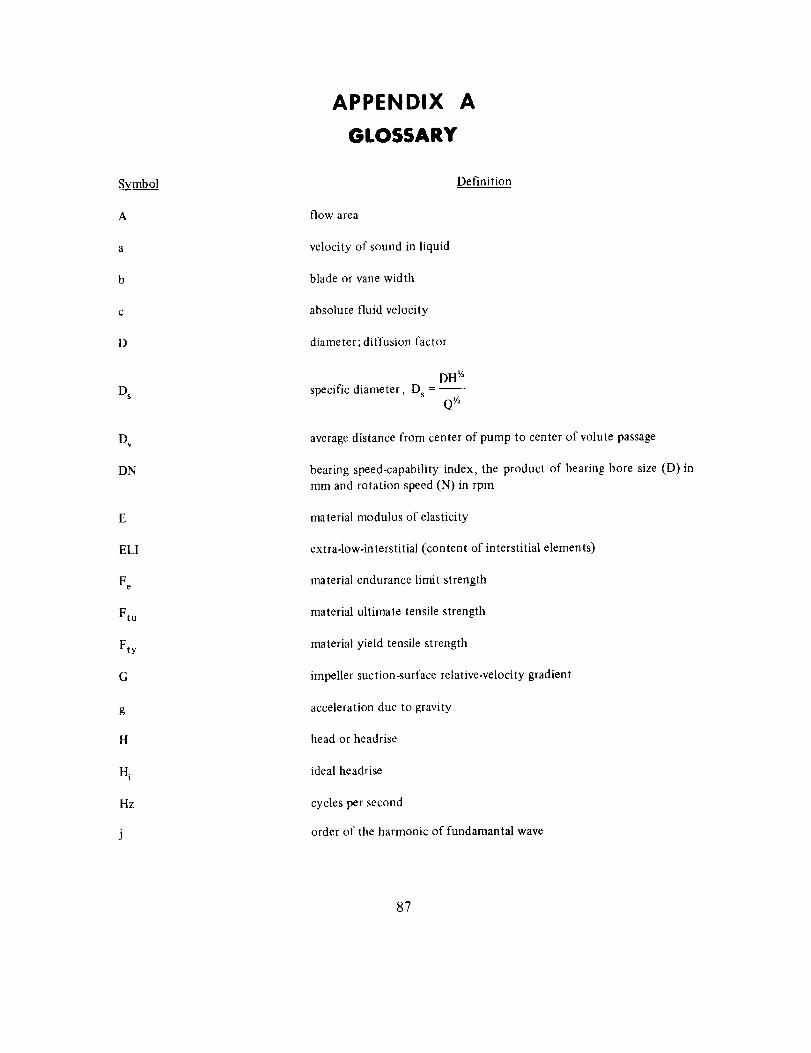
Symbol
A
a
b
C
D
O$
Ov
DN
E
EL1
Fe
Ftu
Fty
G
g
H
Hi
ltz
APPENDIX A
GLOSSARY
Definition
flow area
velocity of sound in liquid
blade or vane width
absolute fluid velocity
diameter; diffusion factor
DH v,specific diameter, Ds = --
QV,
average distance from center of pump to center of volute passage
bearing speed-capability index, the product of bearing bore size (D) in
mm and rotation speed (N) in rpm
material modulus of elasticity
extra-low-interstitial (content of interstitial elements)
material endurance limit strength
material ultimate tensile strength
material yield tensile strength
impeller suction-surface relative-velocity gradient
acceleration due to gravity
head or headrise
ideal headrise
cycles per second
order of the harmonic of fundamantal wave
87
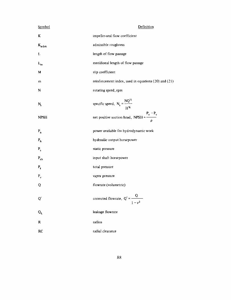
_'mbol
K
Kadm
L
Lm
M
m
N
NPSH
Pa
Ph
Pt
Pv
O
I
QL
R
RC
Definition
impeller-seal flow coefficient
admissible roughness
length of flow passage
meridional length of flow passage
slip coefficient
reinforcement index, used in equations (20) and (21)
rotating speed, rpm
NQ IAspecific speed, N s = --
H _
Pt - Pvnet positive suction head, NPSH = --
P
power available for hydrodynamic work
hydraulic output horsepower
static pressure
input shaft horsepower
total pressure
vapor pressure
flowrate (volumetric)
qcorrected flowrate, Q' = --
1 - v2
leakage flowrate
radius
radial clearance
88
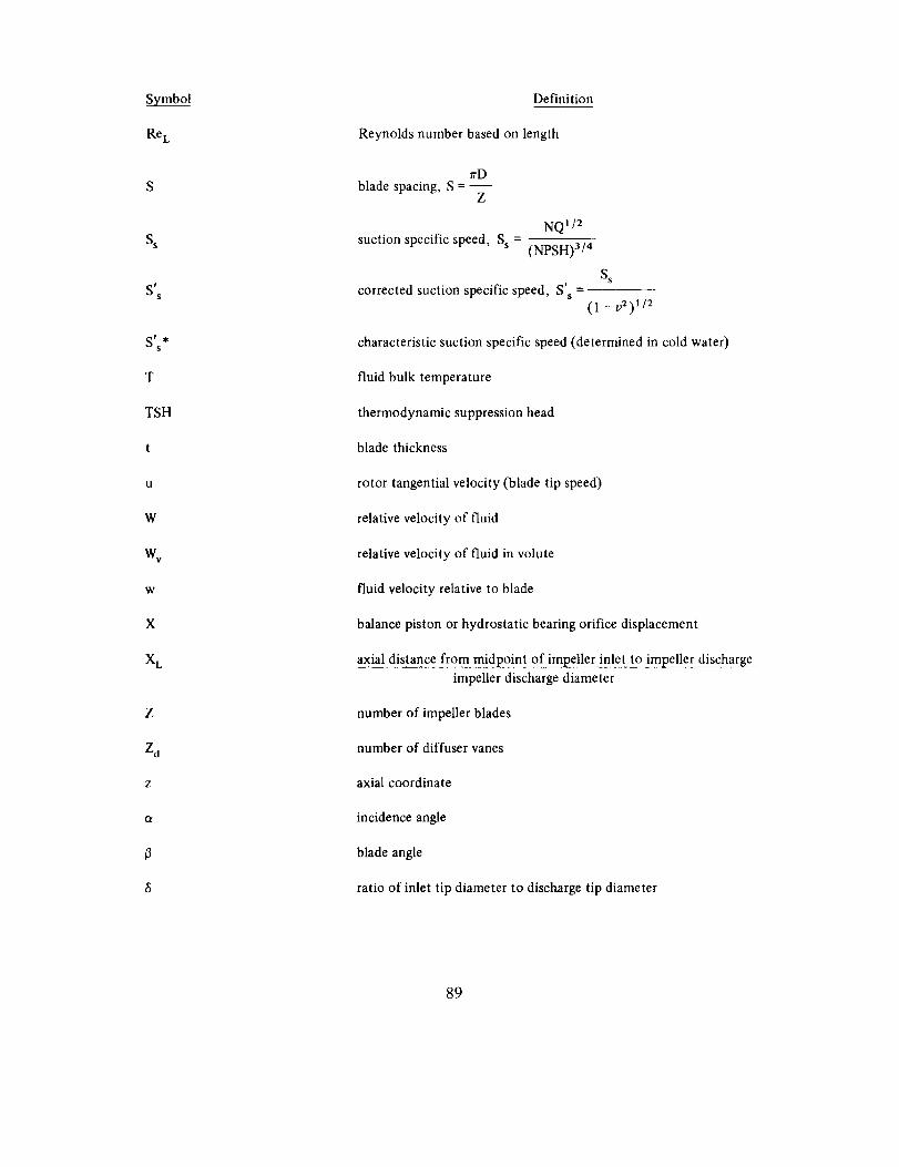
Symbo_l
Re L
S
S s
sSs
S_'s
T
TSH
t
U
W
w,
W
X
XL
Z
Z d
z
ot
Definition
Reynolds number based on length
7rDblade spacing, S = --
Z
suction specific speed, Ss =NQI/2
(NPSH)3/4
S s
corrected suction specific speed, S' s(1 - v2) 1/2
characteristic suction specific speed (determined in cold water)
fluid bulk temperature
thermodynamic suppression head
blade thickness
rotor tangential velocity (blade tip speed)
relative velocity of fluid
relative velocity of fluid in volute
fluid velocity relative to blade
balance piston or hydrostatic bearing orifice displacement
axial distance from midpoint of impeller inlet to impeller discharge
impeller discharge diameter
number of impeller blades
number of diffuser vanes
axial coordinate
incidence angle
blade angle
ratio of inlet tip diameter to discharge tip diameter
89
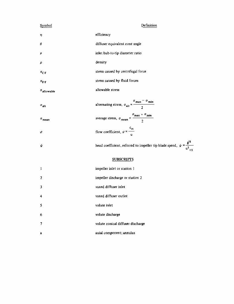
Symbol
P
P
OC F
°FF
(/allowable
OaR
0 ITleall
_o
Definition
efficiency
diffuser equivalent cone angle
inlet hub-to-tip diameter ratio
density
stress caused by centrifugal force
stress caused by fluid forces
allowable stress
alternating stress, O'al t =
O max -- O" rain
2
average stress, amean =Oma x + Omi n
C m
flow coefficient, ¢ = --U
head coefficient, referred to impeller tip blade speed, _k = --
SUBSCRIPTS
impeller inlet or station 1
impeller discharge or station 2
vaned diffuser inlet
vaned diffuser outlet
volute inlet
volute discharge
volute conical diffuser discharge
axial component; annulus
gH
u212
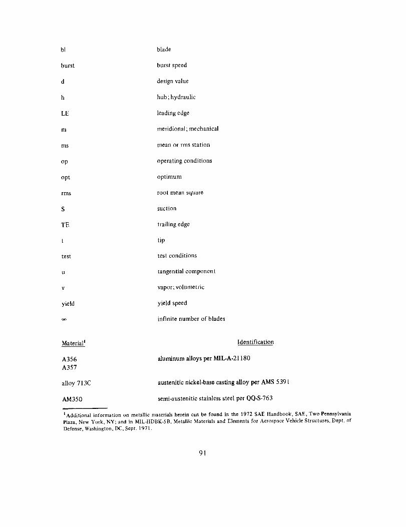
bl
burst
d
h
LE
m
ms
op
opt
rms
S
TE
t
test
u
v
yield
Oo
blade
burst speed
design value
hub ; hydraulic
leading edge
meridional; mechanical
mean or rms station
operating conditions
optimum
root mean square
suction
trailing edge
tip
test conditions
tangential component
vapor; volumetric
yield speed
infinite number of blades
Material _
A356
A357
alloy 713C
AM350
Identification
aluminum alloys per MIL-A-21180
austenitic nickel-base casting alloy per AMS 5391
semi-austenitic stainless steel per QQ-S-763
l Additional information on metallic materials herein can be found in the 1972 SAE Handbook, SAE, Two Pennsylvania
Plaza, New York, NY; and in MIL-HDBK-5B, Metallic Materials and Elements for Aerospace Vehicle Structures, Dept. of
Defense, Washington, DC, Sept. 1971.
91
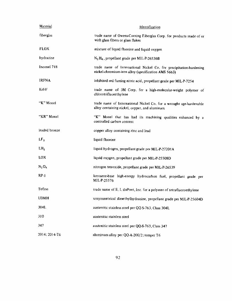
Material
fiberglas
FLOX
hydrazine
Inconel718
IRFNA
Kel-F
"K" Monel
"KR" Monel
leaded bronze
LF2
LH2
LOX
N2 04
RP-1
Teflon
UDMH
304L
310
347
2014; 2014-T6
Identification
trade name of Owens-Coming Fiberglas Corp. for products made of or
with glass fibers or glass flakes
mixture of liquid fluorine and liquid oxygen
N2 H4, propellant grade per MIL-P-26536B
trade name of International Nickel Co. for precipitation-hardening
nickel-chromium-iron alloy (specification AMS 5663)
inhibited red fuming nitric acid, propellant grade per MIL-P-7254
trade name of 3M Corp. for a high-molecular-weight polymer ofchlorotrifluorethylene
trade name of International Nickel Co. for a wrought age-hardenable
alloy containing nickel, copper, and aluminum
"K" Monel that has had its machining qualities enhanced by acontrolled carbon content
copper alloy containing zinc and lead
liquid fluorine
liquid hydrogen, propellant grade per MIL-P-27201A
liquid oxygen, propellant grade per M|L-P-25508D
nitrogen tetroxide, propellant grade per MIL-P-26539
kerosene-base high-energy hydrocarbon fuel, propellant grade perMIL-P-25576
trade name of E. I. duPont, Inc. for a polymer of tetrafluoroethylene
unsymmetrical dimethylhydrazine, propellant grade per MIL-P-25604D
austenitic stainless steel per QQ-S-763, Class 304L
austenitic stainless steel
austenitic stainless steel per QQ-S-763, Class 347
aluminum alloy per QQ-A-200/2 ; temper T6
92
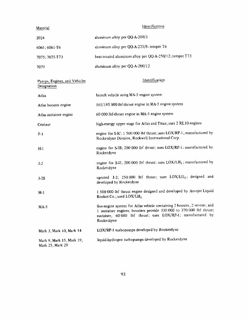
Material
2024
6061;6061-T6
7075;7075-T73
7079
Pumps, Engines, and Vehicles
Designation
Atlas
Atlas booster engine
Atlas sustainer engine
Centaur
F-1
H-I
J-2
J-2S
M-1
MA-5
Mark 3, Mark 10, Mark 14
Mark 9, Mark 15, Mark 19,Mark 25, Mark 29
Identification
aluminum alloy per QQ-A-200/3
aluminum alloy per QQ-A-225/8; temper T6
heat-treated aluminum alloy per QQ-A-250/12; temper T73
aluminum alloy per QQ-A-200/12
Identification
launch vehicle using MA-5 engine system
165/185 000 lbf-thrust engine in MA-5 engine system
60 000 lbf-thrust engine in MA-5 engine system
high-energy upper stage for Atlas and Titan; uses 2 RL10 engines
engine for S-IC; 1 500 000 lbf thrust; uses LOX/RP-1 ; manufactured byRocketdyne Division, Rockwell International Corp.
engine for S-IB; 200 000 lbf thrust; uses LOX/RP-1 ; manufactured by
Rocketdyne
engine for S-II; 200 000 lbf thrust; uses LOX/LH2 ; manufactured by
Rocketdyne
uprated J-2; 250000 lbf thrust; uses LOX/LH2; designed and
developed by Rocketdyne
1 500 000 lbf thrust engine designed and developed by Aerojet Liquid
Rocket Co.; used LOX/LH2
five-engine system for Atlas vehicle containing 2 booster, 2 vernier, and
1 sustainer engines; boosters provide 330000 to 370 000 lbf thrust;
sustainer, 60000 lbf thrust; uses LOX/RP-1; manufactured by
Rocketdyne
LOX/RP-I turbopumps developed by Rocketdyne
liquid-hydrogen turbopumps developed by Rocketdyne
93
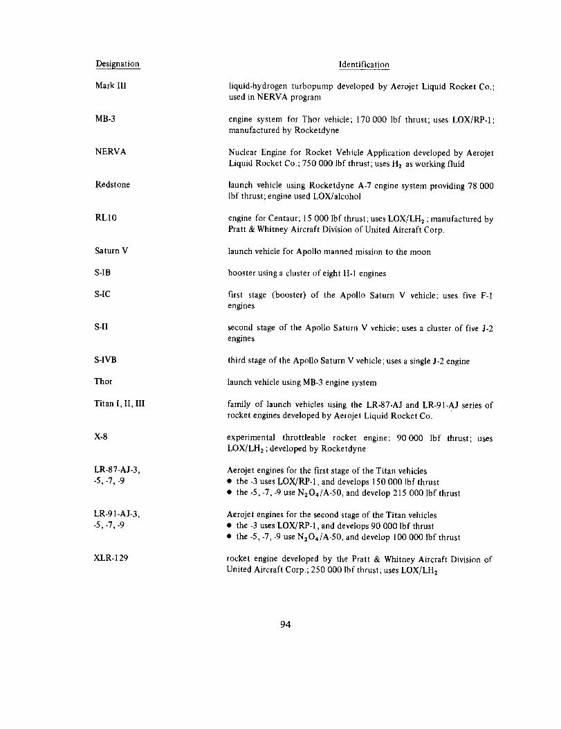
Designation
Mark IIl
MB-3
NERVA
Redstone
RL10
Saturn V
S-IB
S-IC
S-II
S-IVB
Thor
Titan I, II, Ill
X-8
LR-87-AJ-3,-5, -7, -9
XLR- 129
Identification
liquid-hydrogen turbopump developed by Aerojet Liquid Rocket Co.;
used in NERVA program
engine system for Thor vehicle; 170 000 lbf thrust; uses LOX/RP-1;
manufactured by Rocketdyne
Nuclear Engine for Rocket Vehicle Application developed by AerojetLiquid Rocket Co.; 750 000 lbf thrust; uses H2 as working fluid
launch vehicle using Rocketdyne A-7 engine system providing 78 000lbf thrust; engine used LOX/alcohol
engine for Centaur; 15 000 lbf thrust;uses LOX/LH2 ;manufactured by
Pratt & Whitney Aircraft Division of United Aircraft Corp.
launch vehicle for Apollo manned mission to the moon
booster using a cluster of eight H-1 engines
first stage (booster) of the Apollo Saturn V vehicle; uses five F-1
engines
second stage of the Apollo Saturn V vehicle; uses a cluster of five J-2engines
third stage of the Apollo Saturn V vehicle ; uses a single J-2 engine
launch vehicle using MB-3 engine system
family of launch vehicles using the LR-87-AJ and LR-91-AJ series of
rocket engines developed by Aerojet Liquid Rocket Co.
experimental throttleable rocket engine; 90000 lbf thrust; uses
LOX/LH2 ; developed by Rocketdyne
Aerojet engines for the first stage of the Titan vehicles
• the -3 uses LOX/RP-1, and develops 150 000 lbf thrust
• the -5, -7, -9 use N2 O4/A-50, and develop 215 000 lbf thrust
Aerojet engines for the second stage of the Titan vehicles
• the -3 uses LOX/RP-I, and develops 90 000 lbf thrust
• the -5,-7, -9 use N204/A-50 , and develop 100 000 lbf thrust
rocket engine developed by the Pratt & Whitney Aircraft Division of
United Aircraft Corp.; 250 000 lbf thrust; uses LOX/LH2
94
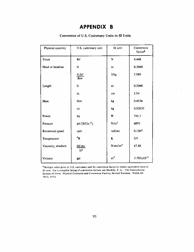
APPENDIX B
Conversion of U.S. Customary Units to SI Units
Physical quantity
Force
Head or headrise
Length
Mass
Power
Pressure
Rotational speed
Temperature
Viscosity, absolute
Volume
U.S. customary unit
lbf
fi
ft-lbf
Ibm
ft
in.
Ibm
oz
hp
psi (Ibf/in. 2)
rpm
oR
lbf-sec
ft 2
gal
SI unit
N
m
J/kg
m
cm
kg
kg
W
N/m 2
rad/sec
K
N-sec/m 2
m 3
Conversion
factor a
4.448
0.3048
2.989
0.3048
2.54
0.4536
0.02835
745.7
6895
0.1047
5/9
47.88
3.785x10 "3
aMultiply value given in U.S. customary unit by conversion factor to obtain equivalent value in
SI unit. For a complete listing of conversion factors, see Mechtly, E. A.: The International
System of Units. Physical Constants and Conversion Factors, Second Revision. NASA SP-
7012, 1973.
95

96
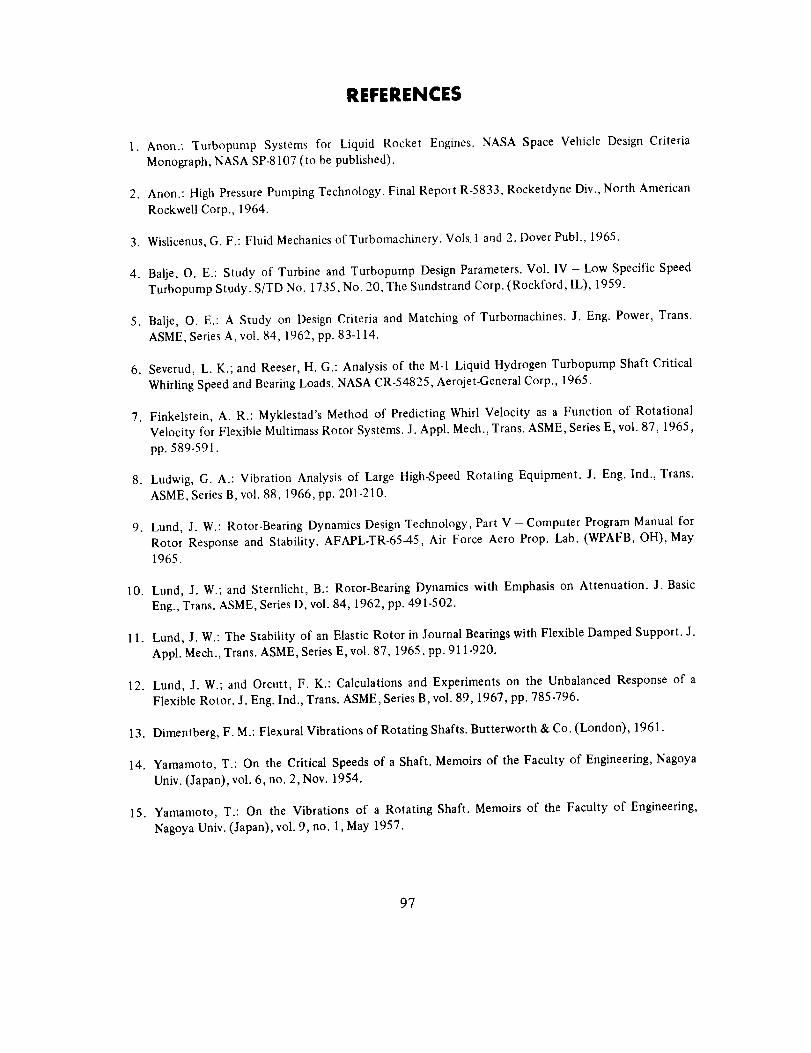
REFERENCES
1. Anon.: Turbopump Systems for Liquid Rocket Engines. NASA Space Vehicle Design Criteria
Monograph, NASA SP-8107 (to be published).
2. Anon.: High Pressure Pumping Technology. Final Report R-5833, Rocketdyne Div., North American
Rockwell Corp., 1964.
3. Wislicenus, G. F.: Fluid Mechanics of Turbomachinery. Vols. 1 and 2. Dover Publ., 1965.
4. Balje, O. E.: Study of Turbine and Turbopump Design Parameters. Vol. IV - Low Specific Speed
Turbopump Study. S/TD No. 1735, No. 20, The Sundstrand Corp. (Rockford, IL), 1959.
5. Balje, O. E.: A Study on Design Criteria and Matching of Turbomachines. J. Eng. Power, Trans.
ASME, Series A, vol. 84, 1962, pp. 83-114.
6. Severud, L. K.; and Reeser, H. G.: Analysis of the M-1 Liquid Hydrogen Turbopump Shaft Critical
Whirling Speed and Bearing Loads. NASA CR-54825, Aerojet-General Corp., 1965.
7. Finkelstein, A. R.: Myklestad's Method of Predicting Whirl Velocity as a Function of Rotational
Velocity for Flexible Multimass Rotor Systems. J. Appl. Mech., Trans. ASME, Series E, vol. 87, 1965,
pp. 589-591.
8. Ludwig, G. A.: Vibration Analysis of Large High-Speed Rotating Equipment. J. Eng. Ind., Trans.
ASME, Series B, vol. 88, 1966, pp. 201-210.
9. Lund, J. W.: Rotor-Bearing Dynamics Design Technology, Part V - Computer Program Manual for
Rotor Response and Stability. AFAPL-TR-65-45, Air Force Aero Prop. Lab. (WPAFB, OH), May
1965.
10. Lund, J. W.; and Sternticht, B.: Rotor-Bearing Dynamics with Emphasis on Attenuation. J. Basic
Eng., Trans. ASME, Series D, vol. 84, 1962, pp. 491-502.
11. Lund, J. W.: The Stability of an Elastic Rotor in Journal Bearings with Flexible Damped Support. J.
Appl. Mech., Trans. ASME, Series E, vol. 87, 1965, pp. 911-920.
12. Lund, J. W.; and Orcutt, F. K.: Calculations and Experiments on the Unbalanced Response of a
Flexible Rotor. J. Eng. Ind., Trans. ASME, Series B, vol. 89, 1967, pp. 785-796.
13. Dimentberg, F. M.: Flexural Vibrations of Rotating Shafts. Butterworth & Co. (London), 1961.
14. Yamamoto, T.: On the Critical Speeds of a Shaft. Memoirs of the Faculty of Engineering, Nagoya
Univ. (Japan), vol. 6, no. 2, Nov. 1954.
15. Yamamoto, T.: On the Vibrations of a Rotating Shaft. Memoirs of the Faculty of Engineering,
Nagoya Univ. (Japan), vol. 9, no. 1, May 1957.
97
16.Yamamoto,T.: OnCriticalSpeedsof aShaftSupportedbyBallBearings.J.Appl.Mech.,Trans.ASME,SeriesE,vol.81,1959,pp.199-204.
17.Wirt,L. A.:AnIntroductionto theWorksofToshioYamamotoWhichTreattheVibrationProblemsEncounteredinHigh-SpeedRotatingMachinery.StrainGageReadings,vol.V,no.1,April-May1962,pp.7-20.
18. Rieger,N. F.: Rotor-BearingDynamicsDesignTechnology.Part l-State of the Art.AFAPL-TR-64-45,AirForceAero.Prop.Lab.(WPAFB,OH),May1965.
19.Poritsky,H.: Rotor-BearingDynamicsDesignTechnology.Part II- RotorStabilityTheory.AFAPL-TR-64-45,AirForceAero.Prop.Lab. (WPAFB, OH),May 1965.
20. Lund, J. W.; et al.: Rotor-Bearing Dynamics Design Technology. Part III- Design Handbook for
Fluid Film Type Bearings. AFAPL-TR-65-45, Air Force Aero. Prop. Lab. (WPAFB, OH), May 1965.
21. Lewis, P.; and Malanoski, S. B.: Rotor-Bearing Dynamics Design Technology. Part IV - Ball BearingDesign Data. AFAPL-TR-65-45, Air Force Aero. Prop. Lab. (WPAFB, OH), May 1965.
22. Hamburg, G.; and Parkinson, J. P.: Gas Turbine Shaft Dynamics. Paper 382B, SAE Summer Meeting(St. Louis, MO), June 5-9, 1961.
23. Alford, J. S.: Protecting Turbomachinery from Self-Excited Whirl. J. Eng. Power, Trans. ASME,Series A, vol. 87, 1965, pp. 333-344.
24. Ehrich, F.: The Influence of Trapped Fluids on High Speed Rotor Vibrations. J. Eng. Ind., Trans.ASME, Series B, vol. 89, 1967, pp. 806-812.
25. Ehrich, F. F.; Subharmonic Vibration of Rotors in Bearing Clearance. ASME paper 66-MD-1, ASME
Design Engineering Conference and Show (Chicago, IL), May 9-12, 1966.
26. Macchia, D.: Acceleration of an Unbalanced Rotor Through the Critical Speed. Paper 63-WA-9,ASME Winter Annual Mtg., Nov. 17-22, 1963.
27. Baker, J. G.: Mathematical-Machine Determination of Vibration of an Accelerated Unbalanced Rotor.
J. Appi. Meck., Trans. ASME, Series E, vol. 61, 1939, pp. A-145 through A-150.
28. McCann, G.D. Jr.; and Bennett, R. R.: Vibration of Multifrequency Systems During Acceleration
through Critical Speeds. J. Appl. Mech., Trans. ASME, Series E, vol. 71, 1949, pp. 375-382.
29. Mironenko, G.: Titan III M-87 High Speed Shaft Critical Speed and Bearing Load Analysis.SA-MOL-TPA-223, Aerojet-General Corp. (Sacramento, CA), July 15, 1966.
30. Howitt, F.: Accelerating a Rotor Through a Critical Speed. The Engineer, vol. 212, no. 5518, Oct. 27,1961, pp. 691-692.
98
31. Linn, F. C.; and Prohl, M. A.: The Effect of Flexibility of Support Upon the Critical Speeds of High
Speed Rotors. Trans. Soc. Naval Arch. and Marine Engrs., vol. 59, 1951.
32. Anon.: Liquid Rocket Engine Turbopump Shafts and Couplings. NASA Space Vehicle Design Criteria
Monograph, NASA SP-8101, Sept. 1972.
33. Anon.: Liquid Rocket Engine Turbopump Inducers. NASA Space Vehicle Design Criteria Monograph,
NASA SP-8052, May 1971.
34. Meng, P. R.; and Connelly, R. E.: Investigation of Effects of Simulated Nuclear Radiation Heating on
Inducer Performance in Liquid Hydrogen. NASA TMX-1359, 1967.
35. Anon.: Evaluation of NPSH Performance of the Model Mark-3 Lox Turbopump Used in the Thor
MB-3 Propulsion System. R-6995, Rocketdyne Div., North American Rockwell Corp., Apr. 21,1967.
36. Saleman, V.: Cavitation and NPSH Requirements of Various Liquids. J. Basic Eng., Trans. ASME,
Series D, vol. 81, 1959, pp. 167-173.
37. James, J. B.: Development of the Liquid Hydrogen Turbopump for the J-2 Rocket Engine (U). Paper
presented at AIAA Propulsion Specialists Conference, Air Force Academy (Colorado Springs, CO),
June 14-18, 1965. (Confidential).
38. Stepanoff, A. J.: Cavitation in Centrifugal Pumps with Liquids Other than Water. J. Eng. Power.,
Trans. ASME, Series A. vol. 83, 1961, pp. 79-90.
39. James, J. B.: J-2X Turbomachinery Report for 1967. Report TSM 8115-2005, Rocketdyne Div.,
North American Rockwell Corp., Feb. 1968.
40. King, J. A.: Design of Inducers for Two-Phase Operation, Final Report. R-8283, Rocketdyne Div.,
North American Rockwell Corp., July 1970.
41. Ruggeri, R. S.; and Moore, R. D.: Method for Prediction of Pump Cavitation Performance for Various
Liquids, Liquid Temperatures, and Rotative Speeds. NASA TN D-5292, 1969.
42. Anon.: Liquid Rocket Engine Turbines. NASA Space Vehicle Design Criteria Monograph, NASA
SP-8110 (to be published).
43. Anon.: Liquid Rocket Engine Turbopump Bearings. NASA Space Vehicle Design Criteria Monograph,
NASA SP-8048, Mar. 1971.
44. Anon.; Liquid Rocket Engine Turbopump Rotating Shaft Seals. NASA Space Vehicle Design Criteria
Monograph (to be published).
45. Williams, F. B.: Design, Fabricate and Test Breadboard Liquid Hydrogen Pump (U). Final Report
July 1,1966 - July 15, 1967, PWA FR-2184, Pratt & Whitney Aircraft, Div. of United Aircraft Corp.
(West Palm Beach, FL), 1967. (Confidential).
99
46. Ball, C. L.; Meng, P. R.; and Reid, L.: Cavitation Performance of 84 ° Helical Pump Inducer Operatedin 37 ° and 42 ° Liquid Hydrogen. NASA TM X-1360, Feb. 1967.
47. Bullock, R. O.: Analysis of Reynolds Number and Scale Effects on Performance of Turbomachinery.J. Eng. Power, Trans. ASME, Series A, vol. 86, 1964, pp. 247-256.
48. Hildebrand, P.; et al.: Centrifugal Pump (High Pressure) for Power Transmissions. Rep. No.AFAPL-TR-66-12 (AD-480108), The Garrett Corporation, 1966.
49. Stepanoff, A. J.: Volute vs Diffuser Casings for Centrifugal Pumps. Proceedings National Conference
on Industrial Hydraulics, Oct. 18-19, 1950, pp. 55-74. Publ. Armour Research Foundation, Chicago,IL, 1951.
*50. Hansen, O.: Untersuchungen Uber den Einfluss des Endlichen Schaufelabstandes in Radialen
Kreiselradern. Verlag Kanrad Triltsh, (Wurzburg, Germany), 1937.
5 I. Anisimov, S. A.; et al.: Study of the Efficiency of Centrifugal Compressor Wheels with a Two-Stage
Vane Cascade. Translation from Russian Periodical, Energomashinostroenie, No. 221, 1962;
AD-400535, Wright Patterson Air Force Base, OH, 1963, pp. 44-68.
52. Vavra, M. H.: Aero-Thermodynamics and Flow in Turbomachines. John Wiley & Sons, Inc., 1960.
53. Katsanis, T.: Use of Arbitrary Quasi-orthogonals for Calculating Flow Distribution in the Meridional
Plane of a Turbomachine. NASA TN D-2546, 1964.
54. Katsanis, T.; and McNally, W. D.: Fortran Program for Calculating Velocities and Streamlines on a
Blade-to-Blade Stream Surface of a Tandem Blade Turbomachine. NASA TN D-5044, 1969.
55. Anon.: Rotating and Positive-Displacement Pumps for Low-Thrust Rocket Engines. Vol.
1-Evaluation and Design; Vol. 2- Fabrication and Testing. NASA CR.72965 and CR-72966,Rocketdyne Div., Rockwell International (to be published).
56. Wiesner, F. J.: A Review of Slip Factors for Centrifugal Impellers. J. Eng. Power, Trans. ASME, SeriesA, vol. 89, 1967, p. 558.
57. Wood, G. M.; Welna, H.; and Lamers, R. P.: Tip Clearance Effects in Centrifugal Pumps. Paper No.64-WA/FE-17, ASME Winter Annual Mtg. (New York, NY), 1964.
58. Hoshide, R. K.; and Nielson, C. E.: Study of Blade Clearance Effects on Centrifugal Pumps. NASA
CR-120815, Rocketdyne Div., North American Rockwell Corp., Nov. 1972.
59. Wolf, J. E.: Fabrication Techniques for Shrouded Titanium Impeller-Final Report. R-8061,Rocketdyne Div., North American Rockwell Corp., 1969.
*Dossier for design criteria monograph "Liquid Rocket Engine Centrifugal Flow Pumps." Unpublished, 1968. Collectedsource material available for inspection at NASA Lewis Research Center, Cleveland, Ohio.
100
60. Wolf, J. E.: Titanium Pump hnpeller Testing Final Report. TMR 0115-3141, Rocketdyne Div.,
North American Rockwell Corp., 1971.
61. Radowski, P. P.; Davis, R. M.; and Bolduc, M. R.: A Numerical Analysis of the Equations of Thin
Shells of Revolution. Paper presented at ARS 15th Annual Mtg. (Washington, DC), Dec. 5-8, 1960.
62. Anon.: Design, Fabricate and Test Breadboard Liquid Hydrogen Pump (U). PWA-FR-1461, NASA
CR-82289, Pratt & Whitney Aircraft, Div. of United Aircraft Corp. (West Palm Beach, FL), July 30,
1965. (Confidential)
63. Kovats, A.: Investigation of Volute- Impeller Interaction in Pumps. ASME Paper No. 66-FE-14,
ASME-EIC Fluids Eng. Conf., Apr. 25-28, 1966.
64. Lazarkiewicz, S.; and Troskolanski, A. T.: Impeller Pumps. Pergamon Press, 1965.
65. Jackson, E. D.: Study of Pump Discharge Pressure Oscillations. Final Report, R-6693-2, Rocketdyne
Div., North American Rockwell Corp., Oct. 1966.
66. Eckert, B.; and Schnell, E.: Axial und Radial Kompressoren. Springer-Verlag (Berlin), 1961.
67. Stepanoff, A. J.: Centrifugal and Axial Flow Pumps. Revised, John Wiley & Sons, Inc., 1960.
68. Pfleiderer, C.: Die Kreiselpumpen fur Flussigkeiten und Gase. Springer-Verlag (Berlin), 1961.
69. Patterson, G. N.: Modern Diffuser Design. Aircraft Eng., vol. 10, no. 115, Sept. 1938, pp. 267-273.
*70. Jakobsen, J. K.: Hydrodynamic Design of the Mark 22 Diffuser and Scroll Section. Internal Report,
TAMR 6115-5, Rocketdyne Div., North American Rockwell Corp., June 1966.
71. McDonald, A. T.; and Fox, R. W.: An Experimental Investigation oflncompressible Flow in Conical
Diffusers. International Journal of Mechanical Sciences, vol. 8, Feb. 1966, pp. 125-139.
72. Rutschi, K.: The Effect of Guide Arrangements on the Output Efficiency of Centrifugal Pumps.
British Hydromechanics Res. Assoc., (Cranfield, Eng.). Trans. into English from Schweizerische
Bauzeitung (Zurich), vol. 79, no. 15, Apr. 1961.
73. Strub, R. A.: Pressure Fluctuations and Fatigue Stresses in Storage Pumps and Pump Turbines. J.
Eng. Power, Trans. ASME, Series A, vol. 86, 1964, pp. 191-194.
74. Brown, W. B.; and Bradshaw, G. R.: Design and Performance of Family of Diffusing Scrolls with
Mixed-Flow Impeller and Vaneless Diffuser. NACA Report 936, 1949.
75. Knapp, R. T.: Centrifugal-Pump Performance as Affected by Design Features. Trans. ASME, vol. 63,
1941, pp. 251-260.
*Dossier for design criteria monograph "Liquid Rocket Engine Centrifugal Flow Pumps." Unpublished, 1968. Collected
source rnaterial available for inspection at NASA Lewis Research Center, Cleveland, Ohio.
101
76.
77.
78.
79.
80.
81.
82.
83.
84.
85.
86.
87.
Becker, E. B.; and Brisbane, J. J.: Application of the Finite-Element Method to Stress Analysis of
Solid Propellant Rocket Grains. Rep. S-76, Rohm & Haas Co., vol. I (AD 474031), Nov. 1965 ; vol II,
part 1 (AD 476515); vol. II, part 2 (AD 476735), Jan. 1966.
Anon.: Liquid Rocket Disconnects, Couplings, Fittings, Joints, and Seals. NASA Space Vehicle
Design Criteria Monograph (to be published).
Anon.: Aerospace Structural Metals Handbook. AFML-TR-68-115, vols. 1, 2, and 3. Air Force
Materials Laboratory (WPAFB, OH), 1969.
Due, H. F. Jr.: An Empirical Method for Calculating Radial Pressure Distribution on Rotating Discs.
J. Eng. Power, Trans. ASME, Series A, vol. 88, 1966, pp 188-196.
Young, W. E.; and Due, H. F.: Investigation of Pressure Prediction Methods for Low-Flow Radial
Impellers, Phase III. PWA FR-1761, Pratt & Whitney Aircraft, Div., United Aircraft Corp. (West Palm
Beach, FL), Jan. 13, 1966.
Watters, W. E.; and Luehr, L.: Development of Steady-State and Dynamic Performance Prediction
Methods for Turbopump Self-Compensating Thrust Balance Systems. NASA CR-72630,
Aerojet-General Corp., (Sacramento, CA), Mar. 1970.
Anon.: Mechanical Design Aspects of Centrifugal Impellers with High Tip Speed Capability (U). Rep.
7446-01F (AD 350716), Aerojet-General Corp., Mar. 1963. (Confidential).
Anon.: Mechanical Design Aspects of Centrifugal Impellers with High Tip Speed Capability: The
Results of Experimental Program (If). Phase II Final Rep. 7446-01F (AD 340146), Aerojet-General
Corporation, Aug. 1963. (Confidential).
Anon.: Testing Compatibility of Materials for Liquid Oxygen Systems. MSFC-Spec-IO6A, Marshall
Space Flight Center (Huntsville, AL), Sept. 1966.
Uhlig, H. H.: Corrosion and Corrosion Control. Second ed., John Wiley & Sons, Inc. (NY), 1971.
Fontana, M. G.; and Greene, N. D.: Corrosion Engineering. McGraw-Hill Book Co. (NY), 1967.
Young, W. E., et al: Investigation of Pressure Prediction Methods for Low Flow Radial Impellers,
Phase II. UAC-PFR-1276, United Aircraft Corporation (E. Hartford, Conn.), Mar. 1965.
102

NASA SPACE VEHICLE DESIGN CRITERIAMONOGRAPHS ISSUED TO DATE
ENVIRONMENT
SP-8005
SP-8010
SP-8011
SP-8013
SP-8017
SP-8020
SP-8021
SP-8023
SP-8037
SP-8038
SP-8049
SP-8067
SP-8069
SP-8084
SP-8085
SP-8091
SP-8092
Solar Electromagnetic Radiation, Revised May 1971
Models of Mars Atmosphere (1967), May 1968
Models of Venus Atmosphere (1972), Revised September 1972
Meteoroid Environment Model-1969 (Near Earth to Lunar Surface),March 1969
Magnetic Fields-Earth and Extraterrestrial, March 1969
Mars Surface Models (1968), May 1969
Models of Earth's Atmosphere (90 to 2500 km),Revised March 1973
Lunar Surface Models, May 1969
Assessment and Control of Spacecraft Magnetic Fields, September 1970
Meteoroid Environment Model- 1970 (Interplanetary and Planetary),October 1970
The Earth's Ionosphere, March 1971
Earth Albedo and Emitted Radiation, July 1971
The Planet Jupiter (1970), December 1971
Surface Atmospheric Extremes (Launch and Transportation Areas),May 1972
The Planet Mercury (1971), March 1972
The Planet Saturn (1970), June 1972
Assessment and Control of Spacecraft Electromagnetic Interference,June 1972
103
SP-8103
SP-8105
STRUCTURES
SP-8001
SP-8002
SP-8003
SP-8004
SP-8006
SP-8007
SP-8008
SP-8009
SP-8012
SP-8014
SP-8019
SP-8022
SP-8029
SP-8030
SP-8031
SP-8032
SP_035
SP-8040
SP-8042
SP-8043
The Planets Uranus, Neptune, and Pluto (1971), November 1972
Spacecraft Thermal Control, May 1973
Buffeting During Atmospheric Ascent, Revised November 1970
Flight-Loads Measurements During Launch and Exit, December 1964
Flutter, Buzz, and Divergence, July 1964
Panel Flutter, Revised June 1972
Local Steady Aerodynamic Loads During Launch and Exit, May 1965
Buckling of Thin-Walled Circular Cylinders, Revised August 1968
Prelaunch Ground Wind Loads, November 1965
Propellant Slosh Loads, August 1968
Natural Vibration Modal Analysis, September 1968
Entry Thermal Protection, August 1968
Buckling of Thin-Walled Truncated Cones, September 1968
Staging Loads, February 1969
Aerodynamic and Rocket-Exhaust Heating During Launch and Ascent
May 1969
Transient Loads From Thrust Excitation, February 1969
Slosh Suppression, May 1969
Buckling of Thin-Walled Doubly Curved Shells, August 1969
Wind Loads During Ascent, June 1970
Fracture Control of Metallic Pressure Vessels, May 1970
Meteoroid Damage Assessment, May 1970
Design-Development Testing, May 1970
104
SP-8044
SP-8045
SP-8046
SP-8050
SP-8053
SP-8054
SP-8055
SP-8056
SP-8057
SP-8060
SP-8061
SP-8062
SP-8063
SP-8066
SP-8068
SP-8072
SP_077
SP-8079
SP-8082
SP-8083
SP-8095
SP-8099
QualificationTesting,May1970
AcceptanceTesting,April1970
LandingImpactAttenuationfor Non-Surface-PlaningLanders,April1970
StructuralVibrationPrediction,June1970
NuclearandSpaceRadiationEffectsonMaterials,June1970
SpaceRadiationProtection,June1970
Preventionof CoupledStructure-PropulsionInstabilitv(Pogo),October1970
FlightSeparationMechanisms,October1970
StructuralDesignCriteriaApplicabletoaSpaceShuttle,RevisedMarch1972
CompartmentVenting,November1970
InteractionwithUmbilicalsandLaunchStand,August1970
EntryGasdynamicHeating,January1971
Lubrication,Friction,andWear,June1971
DeployableAerodynamicDecelerationSystems,June1971
BucklingStrengthofStructuralPlates,June1971
AcousticLoadsGeneratedbythePropulsionSystem,June1971
TransportationandHandlingLoads,September1971
StructuralInteractionwithControlSystems,November1971
Stress-CorrosionCrackinginMetals,August1971
DiscontinuityStressesinMetallicPressureVessels,November1971
PreliminaryCriteriafor the FractureControlof SpaceShuttleStructures,June1971
CombiningAscentLoads,May1972
105
SP-8104
GUIDANCEANDCONTROL
SP-8015
SP-8016
SP-8018
SP-8024
SP-8026
SP-8027
SP-8028
SP-8033
SP-8034
SP-8036
SP-8047
SP-8058
SP-8059
SP_065
SP-8070
SP-8071
SP-8074
SP-8078
SP-8086
StructuralInteractionWithTransportationandHandlingSystems,January1973
GuidanceandNavigationforEntryVehicles,November1968
Effectsof StructuralFlexibilityonSpacecraftControlSystems,April1969
SpacecraftMagneticTorques,March1969
SpacecraftGravitationalTorques,May1969
SpacecraftStarTrackers,July1970
SpacecraftRadiationTorques,October1969
EntryVehicleControl,November1969
SpacecraftEarthHorizonSensors,December1969
SpacecraftMassExpulsionTorques,December1969
Effectsof StructuralFlexibilityonLaunchVehicleControlSystems,February1970
SpacecraftSunSensors,June1970
SpacecraftAerodynamicTorques,January1971
SpacecraftAttitudeControlDuringThrustingManeuvers,February1971
TubularSpacecraftBooms(Extendible,ReelStored),February1971
SpaceborneDigitalComputerSystems,March1971
PassiveGravity-GradientLibrationDampers,February1971
SpacecraftSolarCellArrays,May1971
SpaceborneElectronicImagingSystems,June1971
SpaceVehicleDisplaysDesignCriteria,March1972
106
SP-8096
SP-8098
SP-8102
CHEMICALPROPULSION
SP-8087
SP-8081
SP-8052
SP-8048
SP-8101
SP-8094
SP-8097
SP-8090
SP-8080
SP-8064
SP-8075
SP-8076
SP_073
SP_039
SP-8051
SP-8025
SP-8041
SpaceVehicleGyroscope Sensor Applications, October 1972
Effects of Structural Flexibility on Entry Vehicle Control Systems,June 1972
Space Vehicle Accelerometer Applications, December 1972
Liquid Rocket Engine Fluid-Cooled Combustion Chambers, April 1972
Liquid Propellant Gas Generators, March 1972
Liquid Rocket Engine Turbopump Inducers, May 1971
Liquid Rocket Engine Turbopump Bearings, March 1971
Liquid Rocket Engine Turbopump Shafts and Couplings, September1972
Liquid Rocket Valve Components, August 1973
Liquid Rocket Valve Assemblies, November 1973
Liquid Rocket Actuators and Operators, May 1973
Liquid Rocket Pressure Regulators, Relief Valves, Check Valves, Burst
Disks, and Explosive Valves, March 1973
Solid Propellant Selection and Characterization, June 1971
Solid Propellant Processing Factors in Rocket Motor Design, October1971
Solid Propellant Grain Design and Internal Ballistics, March 1972
Solid PropeUant Grain Structural Integrity Analysis, June 1973
Solid Rocket Motor Performance Analysis and Prediction, May 1971
Solid Rocket Motor Igniters, March 1971
Solid Rocket Motor Metal Cases, April 1970
Captive-Fired Testing of Solid Rocket Motors, March 1971
_._ U.S. GOVERNMENT PRINTING OFFICE: 1974--739-161/13_
107


NATIONAL AERONAUTICS AND SPACE ADMINISTRATION
WASHINGTON, D.C, 20546
OFFICIAL BUSINESS
PENALTY FOR PRIVATE USE 1300 SPECIAL FOURTH-CLASS
BOOKRATE
POSTAG Ir AND PERil PAiD
NATIONAL AERONAUTICa AND
IPACE ADMINISTRATION
41l!
POSTMASTER : If Undeliverable (Section 158
Postal Manual) Do Not Return


