

Marine Inquiry 11-201, Passenger vessel Volendam, lifeboat fatality,
Port of Lyttelton, New Zealand, 8 January 2011
The Transport Accident Investigation Commission is an independent Crown entity established to
determine the circumstances and causes of accidents and incidents with a view to avoiding similar
occurrences in the future. Accordingly it is inappropriate that reports should be used to assign fault or
blame or determine liability, since neither the investigation nor the reporting process has been
undertaken for that purpose.
The Commission may make recommendations to improve transport safety. The cost of implementing
any recommendation must always be balanced against its benefits. Such analysis is a matter for the
regulator and the industry.
These reports may be reprinted in whole or in part without charge, providing acknowledgement is made
to the Transport Accident Investigation Commission.

Final Report
Marine Inquiry 11-201, Passenger vessel Volendam, lifeboat
fatality,
Port of Lyttelton, New Zealand, 8 January 2011
Approved for publication: October 2011


Transport Accident Investigation Commission
About the Transport Accident Investigation Commission and this report
The Transport Accident Investigation Commission (Commission) is an independent Crown entity
responsible for inquiring into maritime, aviation and rail accidents and incidents for New Zealand, and
co-ordinating and co-operating with other accident investigation organisations overseas. The principal
purpose of its inquiries is to determine the circumstances and causes of the occurrence with a view to
avoiding similar occurrences in the future. Its purpose is not to ascribe blame to any person or agency
or to pursue (or to assist an agency to pursue) criminal, civil or regulatory action against a person or
agency. The Commission carries out its purpose by informing members of the transport sector, both
domestically and internationally, of the lessons that can be learnt from transport accidents and
incidents.
Commissioners
Chief Commissioner John Marshall, QC
Deputy Chief Commissioner Helen Cull, QC
Commissioner Captain Bryan Wyness
Assessor Keith Ingram
Key Commission personnel
Chief Executive Lois Hutchinson
Chief Investigator of Accidents Captain Tim Burfoot
Investigator in Charge Captain Iain Hill
General Counsel Rama Rewi
Email: [email protected]
Web: www.taic.org.nz
Telephone: + 64 4 473 3112 (24 hrs) or 0800 188 926
Fax: + 64 4 499 1510
Address: Level 16, AXA Centre, 80 The Terrace, PO Box 10 323, Wellington 6143, New Zealand

Important notes
Nature of the final report
This final report has not been prepared for the purpose of supporting any criminal, civil or regulatory
action against any person or agency. The Transport Accident Investigation Commission Act 1990 makes
this final report inadmissible as evidence in any proceedings with the exception of a Coroner‟s inquest.
Ownership of report
This report remains the intellectual property of the Transport Accident Investigation Commission.
This report may be reprinted in whole or in part without charge, provided that acknowledgement is made
to the Transport Accident Investigation Commission.
Citations and referencing
Information derived from interviews during the Commission‟s inquiry into the occurrence is not cited in
this final report. Documents that would normally be accessible to industry participants only and not
discoverable under the Official Information Act 1980 have been referenced as footnotes only. Other
documents referred to during the Commission‟s inquiry that are publicly available are cited.
Photographs, diagrams, pictures
Unless otherwise specified, photographs, diagrams and pictures included in this final report are
provided by, and owned by, the Commission.
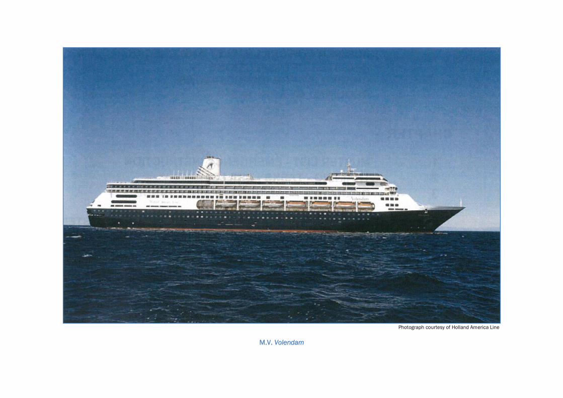
Photograph courtesy of Holland America Line
M.V. Volendam

Legend
Lyttelton
Source: mapsof.net
Location of accident
Contents
1. Executive summary ...................................................................................................................................1
Summary ....................................................................................................................................................1
Key lessons ................................................................................................................................................1
2. Conduct of the inquiry ...............................................................................................................................2
3. Factual information ...................................................................................................................................3
3.1. Narrative .......................................................................................................................................3
3.2. Vessel information ........................................................................................................................4
3.3. Lifeboat and its launching arrangement .....................................................................................4
Davits ............................................................................................................................................4
Lifeboats ....................................................................................................................................................4
Wire falls ....................................................................................................................................................6
3.4. Inspection and testing ..................................................................................................................8
Davit 8
Wire fall ......................................................................................................................................................8
3.5. Personnel information ............................................................................................................... 11
3.6. On board working practices ...................................................................................................... 12
3.7. Maintenance regime ................................................................................................................. 12
3.8. Survival aspects ......................................................................................................................... 13
4. Analysis ................................................................................................................................................... 15
4.1. Introduction ................................................................................................................................ 15
4.2. Why the lifeboat fall failed ........................................................................................................ 15
4.3. Why the crew members fell into the sea .................................................................................. 16
4.4. The importance of wearing lifejackets when working over water ........................................... 17
4.5. Violation of good company procedures .................................................................................... 18
4.6. Design and maintenance of the lifeboat launching davit ....................................................... 20
5. Findings................................................................................................................................................... 22
6. Safety actions ......................................................................................................................................... 23
Safety actions addressing safety issues identified during an inquiry ................................................. 23
7. Recommendations ................................................................................................................................. 25
General ................................................................................................................................................... 25
Recommendations ................................................................................................................................. 25
Recommendation 1................................................................................................................................ 25
Recommendation 2................................................................................................................................ 25
Recommendation 3................................................................................................................................ 25
8. Key lessons ............................................................................................................................................. 27
9. Citations .................................................................................................................................................. 28
Appendix 1 Navalimpianti Technimpianti Service Bulletin ........................................................................ 29
Appendix 2 Navalimpianti Technimpianti ................................................................................................... 31
Appendix 3 Job hazard analysis sheet 0001 .............................................................................................. 32
Appendix 4 Job hazard analysis sheet 0009 .............................................................................................. 33

Appendix 5 Working aloft permit ................................................................................................................. 34
Appendix 6 Toolbox discussion for .............................................................................................................. 35


Figures
Figure 1 Number 7 lifeboat in vertical position after failure of wire fall ................................................ 3
Figure 2 Diagram of the telescopic davit system as fitted to the Volendam ......................................... 5
Figure 3 Wire fall reeving diagram ............................................................................................................ 6
Figure 4 Diagram of davit construction .................................................................................................... 7
Figure 5 Number 7 forward davit showing moveable trolley beam and wire break point .................... 7
Figure 6 Head of number 7 forward fixed davit arm ............................................................................... 9
Figure 7 Vertical bracket from number 5 trolley beam ........................................................................... 9
Figure 8 Number 5 davit beam (fixed part) showing deflection ........................................................... 10
Figure 9 Photograph of the failure point of number 7 lifeboat forward wire fall ................................. 10
Figure 10 Enlarged photograph of failure point of number 7 lifeboat wire fall...................................... 11
Figure 11 Starboard side of the Volendam looking aft from the navigating bridge showing
position of davit ends and stowage positions ......................................................................... 15
Figure 12 Diagrammatic representation of aft fall hook failure ............................................................. 17

Abbreviations
°C degree(s) Celcius
HAL Holland America Line
ISM code International management code for the safe operation of ships and for pollution
prevention
JHA job hazard analysis
kW kilowatt(s)
LMC Lloyds machinery certificate
m metre(s)
mm millimetre(s)
PPE personal protective equipment
SOLAS International Convention for the Safety of Life at Sea 1974
t tonne(s)
UMS unmanned machinery space certification
UTC co-ordinated universal time
Glossary
new vessels constructed under a classifications society‟s special survey
100 A1 ship considered to be suitable for sea-going service, accepted into class as
complying with the society‟s rules and regulations and carrying on board an
anchor or mooring equipment complying with the society‟s rules.
davit a fitting that can project over a vessel‟s side for attaching tackle for hoisting or
lowering a boat
elastic deformation deformation to an object that is reversible. Once the forces are no longer
applied, the object returns to its original shape
fall wire wire rope by which a lifeboat is hoisted or lowered.
kilo the prefix kilo- denotes a multiple of 1000 in the International System of units
(SI Units)
Newton the absolute unit of force in the International System of units (SI Units). It is
defined as that force necessary to provide a mass of one kilogram with an
acceleration of one metre (m) per second per second.
plastic deformation deformation to an object that is irreversible. However, an object in the plastic
deformation range will first have undergone elastic deformation, which is
reversible, so the object will return part way to its original shape
traveller wires wires attached to a telescopic davit arm, enabling a section of the arm to
extend farther out than the end of the moveable trolley
Data summary
Vessel particulars
Name: Volendam
Type: passenger vessel
Class: SOLAS
Limits: unlimited
Classification: Lloyds Register
LR 100 A1, Passenger Ship, Ice Class 1D
LMC, UMS
Length: 237.90 metres (m)
Breadth: 32.45 m
Gross tonnage: 61 214
Built: Fincantieri Shipyard, Maghera, Italy
Propulsion: Five 8640 kilowatt (kW) diesel generators providing electrical power
for two 13 000 kW electric motors driving two, 4-bladed variable-
pitch propellers
Service speed: 22.5 knots (kts)
Owner:
Operator: HAL Antillen N.V.
HAL Westours Incorporated.
Port of registry: Rotterdam
Minimum crew:
Minimum working
crew
57
620
Date and time
Saturday 8 January 2011, at about 13571
Location
Lyttelton, South Island, New Zealand
Injuries
one fatality
one minor
Damage
one lifeboat constructively lost
one tender/lifeboat repairable damage to hull
1 Times in this report are in New Zealand Daylight Time (UTC + 13 hours) and are expressed in the 24-hour
mode.
Report 11-201 | Page 1
1. Executive summary
Summary
1.1. On the afternoon of 8 January 2011, the passenger vessel Volendam was alongside in
Lyttelton. Some of the crew were carrying out routine maintenance on one of the starboard
lifeboats when at about 1400 the forward lifeboat fall wire parted and 2 crew members fell
into the water; the lifeboat remained suspended by the aft lifeboat fall wire.
1.2. The alarm was raised and a rescue boat and crew were launched shortly afterwards. One of
the crew members who had fallen into the water was recovered by the rescue boat. However,
the other crew member could not be found despite a search being carried out by the vessel‟s
rescue boat, the port authority, the coastguard and emergency services.
1.3. The body was eventually found and retrieved from the sea bed some 4 hours later by port
authority divers. The lifeboat was irreparably damaged and the tender launch aft of the
lifeboat was also damaged, requiring repairs to the hull before the Volendam could sail.
1.4. Both crew members who fell into the water were wearing safety harnesses that were attached
to a line strung between the lifeboat‟s lifting hooks. When the fall wire failed this line also
failed. Neither of the crew members was wearing any form of buoyancy aid or lifejacket.
1.5. A subsequent investigation into the failure mechanism of the forward fall wire showed that the
wire in the failure zone was heavily corroded which caused a loss of structural strength in the
immediate vicinity of the failure. The final failure was due to a tensile fracture of the remaining
cross section of the wire.
1.6. Because of the design of the lifeboat davits, the wire in the vicinity of the failure, was difficult
to access to apply a protective coating of grease to the wire, and it was difficult to ensure that
the coating was applied around the whole circumference of the wire in this area.
1.7. On inspection of the remaining davit systems on board the vessel, 10 fall wires were found to
be sufficiently corroded in an area at or near the fixed point termination to require remedial
action.
1.8. Three urgent safety recommendations were made to the manufacturer of the davit systems, to:
alert all owners of vessels fitted with the SPTDL-150P model of davit fitted to the
Volendam to the circumstances of this accident and issue instructions on what
immediate inspections should be carried out
make a technical assessment of other lifeboat davit models it had produced to identify
similar safety issues existing with these models, and if so alert owners of these models
review the design of the davit system SPTDL-150P with a view to remedying the
tendency in this case for the fixed arm davit to flex inwards under load and contact
moving parts of the structure.
Key lessons
A wire rope is only as good as its weakest part. Unless an inspection covers the entire
length of the wire, a thorough inspection has not been made.
Wire ropes in a marine environment require frequent and thorough lubrication to
prevent corrosion; otherwise other measures will need to be taken to prevent
premature failure of the wire ropes.
When selecting a securing point for a safety harness, consideration should be given to
its vulnerability in the event of other catastrophic failures.
A personal buoyancy device should always be worn when working outside a ship‟s rail.
Robust job hazard analysis (JHA) can prevent injuries and save lives, but only if the
procedures that result are then followed by the crew.

Page 2 | Report 11-201
2. Conduct of the inquiry
2.1. On 8 January 2011 at about 1524, the Transport Accident Investigation Commission
(Commission) learnt from Maritime New Zealand that an accident had occurred earlier that
afternoon on board the passenger ship Volendam while berthed at Lyttelton.
2.2. The accident fell into the category of a “very serious accident” as defined in the International
Maritime Organization‟s casualty investigation code, which requires states to conduct
investigations under the code. The Commission opened an inquiry into the occurrence.
2.3. During the night of 8 January 2011 the Commission was contacted by the Dutch Safety Board
and an agreement was reached that the Commission would investigate the accident in its own
right and also on behalf of the Dutch Safety Board. An agreement was made that New
Zealand would also be the reporting State for the accident to the International Maritime
Organization.
2.4. On 9 January 2011, 2 investigators from the Commission boarded the vessel when it arrived
in Wellington and met with the senior officers on board. After a briefing with the master and
senior officers, the scene of the accident was inspected and members of the crew involved in
the accident and subsequent search and rescue were interviewed. Access to the failed wire
was limited as the vessel was berthed port side to the quay.
2.5. The Volendam sailed from Wellington the same evening and during its subsequent port stays
in Napier, Tauranga and Auckland the failed wire fall was removed and retained by the
Commission. All the remaining wire falls, their attachment arrangements and the davit heads
were inspected by a Lloyds Register Asia surveyor. The Commission received a copy of the
surveyor‟s report.
2.6. The Commission engaged the New Zealand Defence Technology Agency to establish the
nature of the wire failure.
2.7. On 23 February 2011, the Commission approved an interim factual report for publication. The
report included urgent safety recommendations issued to the manufacturer of the davit
system to address safety issues identified.
2.8. On 26 August 2011 the Commission approved a draft final report to be circulated to
interested persons for comment.
2.9. The draft final report was sent to 14 interested persons with a request that submissions be
forwarded to the Commission no later than 30 September 2011. A written submission was
received from Holland America Line on its own behalf and that of its employees. One verbal
submission was received from Maritime New Zealand indicating that it would not be making a
written submission on the report.
2.10. On 26 October 2011 the Commission approved the publication of the final report

Report 11-201 | Page 3
3. Factual information
3.1. Narrative
3.1.1. On Saturday 8 January 2011, the Dutch-registered passenger vessel Volendam berthed in the
port of Lyttelton.
3.1.2. At about 0800, 4 crew members were tasked with the routine maintenance job of greasing the
lifeboat fall and traveller wires on number 7 lifeboat on the starboard side. A “working aloft”
permit was issued for the task, because it required the crew members to be working at height
outboard of the vessel‟s rail. A “Toolbox Discussion” form was signed by all 4 crew members
before starting the task. The crew members started this job at about 0830.
3.1.3. Two of the crew members were standing on the access platform, one greasing the wire falls on
the winch drum and one operating the controls to boom the telescopic davit in and out and
lower and raise the lifeboat as required to facilitate the greasing of the wires.
3.1.4. Two crew members were standing on the top of the lifeboat greasing the wire falls and davit
traveller wires. They were attached by safety harnesses, clipped to a safety line that had been
strung tight between the forward and aft lifeboat lifting hook arrangements, but neither was
wearing a personal flotation device.
3.1.5. At about 1355, the job was nearing completion. The 2 crew members on top of the lifeboat
requested the crew member at the controls to lower the lifeboat a short distance from the
lifeboat‟s extreme height against the davit trolley arm. At this time the davit arm was fully
extended.
3.1.6. As the winch operator was lowering the lifeboat the forward lifeboat wire fall parted and the
lifeboat fell bow down, suspended by the aft lifeboat fall (see Figure 1).
Figure 1 Number 7 lifeboat in vertical position after failure of wire fall
3.1.7. The aft lifting hook bent backwards under the strain, tearing a path through the fibreglass hull
as it did so. As a consequence the safety line rigged between the lifting hooks parted.
Because it was this line to which the crew members had attached their safety harnesses, the
2 crew members on the lifeboat fell about 16 m into the water.
Photograph courtesy of Holland America Line
Page 4 | Report 11-201
3.1.8. The crew on board the Volendam raised the alarm and one of the vessel‟s rescue boats was
launched shortly afterwards. One crew member managed to grab a floating bucket of grease
and use this to help stay afloat. He was rescued. The crew member who had been at the
front of the lifeboat was seen briefly above water in what appeared to others to be a dazed
state, but he soon disappeared. Searches by the vessel‟s crew and emergency services failed
to find him. Later that evening divers recovered his body from the seabed near where he had
fallen into the sea.
3.2. Vessel information
3.2.1. The Volendam was built by Fincantieri Shipyard in Maghera, Italy in 1998. The vessel was
owned by HAL Antillen N.V. of Curacao Dutch Antilles, and operated by HAL Westours
Incorporated of Seattle, Washington, United States of America. The vessel was registered in
Rotterdam, Netherlands and had valid certificates issued by the Dutch Government and by the
Lloyds Register classification society.
3.2.2. The Volendam was a steel-hulled passenger vessel with an overall length of 237.90 m and a
breadth of 34.45 m. The vessel had an international gross tonnage of 61 214. It was
powered by five 8640 kW diesel electric generators powering two 13 000 kW electric motors
driving two 4-bladed variable-pitch propellers, giving a service speed of up to 22.5 knots.
3.2.3. The Volendam was certified to carry 620 crew and 1805 passengers. The vessel was fitted
with 14 motor lifeboats accommodating 1920 persons, 16 davit-launched life rafts
accommodating 560 persons and 18 life rafts accommodating 630 persons.
3.3. Lifeboat and its launching arrangement
Davits
3.3.1. The davits on board the Volendam were designed, manufactured and supplied by
Navalimpianti Tecnimpianti Group to the Fincantieri Shipyard. The davits for the lifeboats
were of SPTDL-150P design and differed from the davits for the cruise tenders and the rescue
boats.
3.3.2. The SPTDL-150P davits were hydraulic telescopic davits that used hydraulic rams to move the
telescopic trolley arms outboard from the stowed position and recover them when necessary.
The system was designed to ensure that both davit trolley arms always moved together2.
Power was provided by 2 centralised hydraulic power packs on the port and starboard sides of
the vessel.
3.3.3. The telescopic trolley arms of the davits were designed to support a safe working load of 86
kilonewtons. The telescopic trolley arms were located on guides on the inner faces of the
fixed arms (see Figure 2). To operate the davits and lower the lifeboats, the lifeboat lashings
were released and the telescopic trolley arm of the davit was hydraulically pushed out to the
fully extended position. The lifeboat was then lowered to the embarkation deck and the davit
arm brought back in to bring the lifeboat against the ship‟s side ready for boarding.
Lifeboats
3.3.4. The lifeboats supplied to the Volendam were designed and manufactured by Schat Harding
and were of the MPC 36 SV partially enclosed lifeboat design. The lifeboats were constructed
from marine-quality laminated glass fibre reinforced plastic; they had an overall length of
10.8 m and a beam of 4.45 m. The lifeboats weighed 5.45 tonnes (t) including loose gear,
and had a capacity of 150 persons. The lifeboat release hooks were of the Tor T12 design
and were 9.40 m apart in the stowed position.
2 Holland America Line, M.V. Volendam, Lifeboat maintenance manual, provided by Fincantieri.

Report 11-201 | Page 5
Figure 2
Diagram of the telescopic davit system as fitted to the Volendam

Page 6 | Report 11-201
Wire falls
3.3.5. The lifeboat wire falls were of 22 millimetre (mm) 6x36 wire strand construction with an
internal wire rope core. The wire falls had a minimum certified breaking strain of
390 kilonewtons. The forward fall was 90 m in length and the after fall was 81 m in length;
they had been manufactured by Vornbäumen Stahlseile of Bad Iburg, Germany. They had
been supplied to the Volendam in late 2005/early 2006 and fitted to number 7 davits on
28 November 2006.
3.3.6. The requirement under the International Convention for the Safety of Life at Sea 1974
(SOLAS) chapter III regulation 20 – operational readiness, maintenance and inspections
paragraph 4 stated that:
Falls used in launching shall be inspected periodically with special regard for areas passing through sheaves, and renewed when necessary due to
deterioration of the falls or at intervals of not more than 5 years, whichever is the
earlier
Holland America Line had designated a renewal period for lifeboat falls of 4 years with routine
inspections at regular intervals. The number 7 ifeboat forward fall had been fitted to the davit
for more than 4 years. The vessel‟s management had noted that the wire fall was due for
replacement, and on 24 November 2010, asked the vessel‟s fleet manager whether to
proceed or defer until the vessel dry docked in March/April 2011 when other work was to be
carried out on the davits. Fleet management agreed to defer the changing of the fall provided
that “a visual inspection of the wires was done and if the wires appeared to be in good shape
the replacement could be deferred until dry dock”. On 29 November a visual inspection of the
wires was recorded as having been undertaken.
Figure 3
Wire fall reeving diagram
Since being fitted to number 7 davit, the fall had been greased on average every 6 weeks by
ship staff using the recommended grease.
3.3.7. The wire falls were wound onto 2 hydraulically-driven winch drums and reeved through a
series of sheaves located on the ship, on the telescopic trolley arms and on the fixed arms.
Both wire falls terminated after passing around fixed guides located on the outboard end of
the fixed arm of the davit (see Figure 3).
Diagram courtesy of Navalimpianti Group
Position of wire failure
Report 11-201 | Page 7
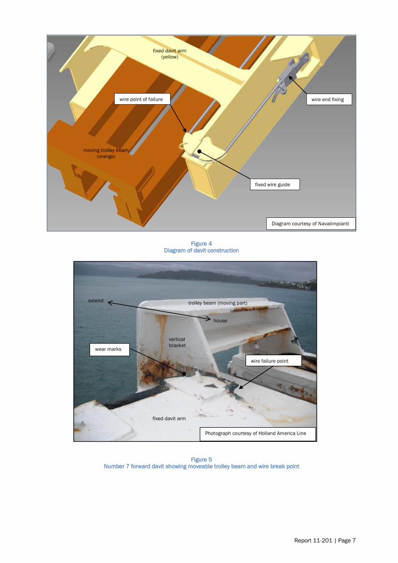
Figure 4 Diagram of davit construction
Figure 5 Number 7 forward davit showing moveable trolley beam and wire break point
Diagram courtesy of Navalimpianti
wire end fixing
moving trolley beam
(orange)
fixed davit arm
(yellow)
wire point of failure
fixed wire guide
Photograph courtesy of Holland America Line
trolley beam (moving part)
fixed davit arm
wire failure point
vertical
bracket wear marks
extend
house
Page 8 | Report 11-201
3.4. Inspection and testing
Davit
3.4.1. After the accident, number 7 telescopic davit was re-housed in its stowed position with the
fixed end of the forward wire fall still in place. This allowed the investigators to view the wire
fall in place before it was removed.
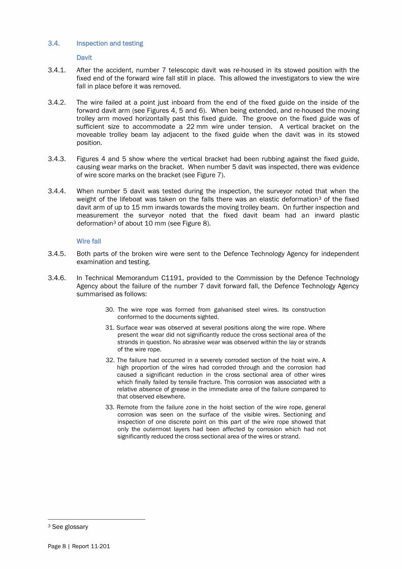
3.4.2. The wire failed at a point just inboard from the end of the fixed guide on the inside of the
forward davit arm (see Figures 4, 5 and 6). When being extended, and re-housed the moving
trolley arm moved horizontally past this fixed guide. The groove on the fixed guide was of
sufficient size to accommodate a 22 mm wire under tension. A vertical bracket on the
moveable trolley beam lay adjacent to the fixed guide when the davit was in its stowed
position.
3.4.3. Figures 4 and 5 show where the vertical bracket had been rubbing against the fixed guide,
causing wear marks on the bracket. When number 5 davit was inspected, there was evidence
of wire score marks on the bracket (see Figure 7).
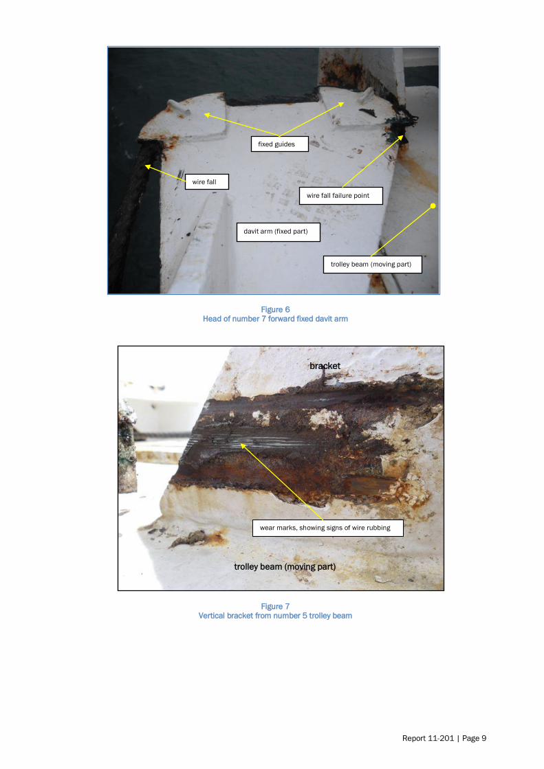
3.4.4. When number 5 davit was tested during the inspection, the surveyor noted that when the
weight of the lifeboat was taken on the falls there was an elastic deformation3 of the fixed
davit arm of up to 15 mm inwards towards the moving trolley beam. On further inspection and
measurement the surveyor noted that the fixed davit beam had an inward plastic
deformation3 of about 10 mm (see Figure 8).
Wire fall
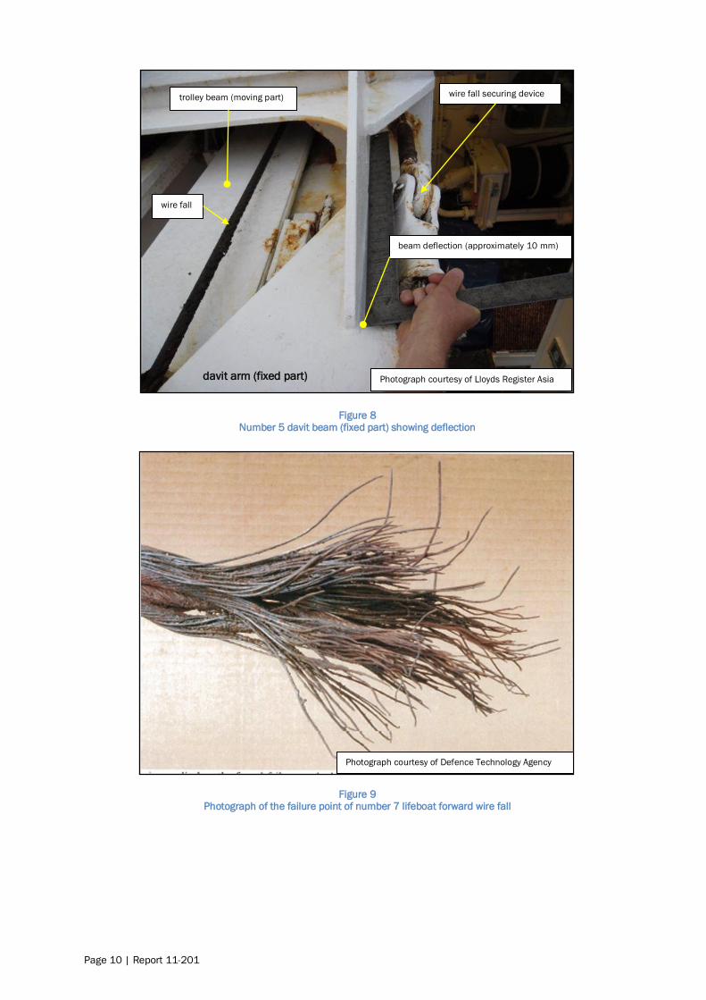
3.4.5. Both parts of the broken wire were sent to the Defence Technology Agency for independent
examination and testing.
3.4.6. In Technical Memorandum C1191, provided to the Commission by the Defence Technology
Agency about the failure of the number 7 davit forward fall, the Defence Technology Agency
summarised as follows:
30. The wire rope was formed from galvanised steel wires. Its construction
conformed to the documents sighted.
31. Surface wear was observed at several positions along the wire rope. Where present the wear did not significantly reduce the cross sectional area of the
strands in question. No abrasive wear was observed within the lay or strands
of the wire rope.
32. The failure had occurred in a severely corroded section of the hoist wire. A
high proportion of the wires had corroded through and the corrosion had
caused a significant reduction in the cross sectional area of other wires
which finally failed by tensile fracture. This corrosion was associated with a relative absence of grease in the immediate area of the failure compared to
that observed elsewhere.
33. Remote from the failure zone in the hoist section of the wire rope, general
corrosion was seen on the surface of the visible wires. Sectioning and
inspection of one discrete point on this part of the wire rope showed that
only the outermost layers had been affected by corrosion which had not
significantly reduced the cross sectional area of the wires or strand.
3 See glossary
Report 11-201 | Page 9
Figure 6 Head of number 7 forward fixed davit arm
Figure 7 Vertical bracket from number 5 trolley beam
wire fall failure point
fixed guides
trolley beam (moving part)
davit arm (fixed part)
wire fall
bracket
wear marks, showing signs of wire rubbing
trolley beam (moving part)
Page 10 | Report 11-201
Figure 8
Number 5 davit beam (fixed part) showing deflection
Figure 9 Photograph of the failure point of number 7 lifeboat forward wire fall
davit arm (fixed part)
trolley beam (moving part)
wire fall
wire fall securing device
Photograph courtesy of Lloyds Register Asia
beam deflection (approximately 10 mm)
Photograph courtesy of Defence Technology Agency

Report 11-201 | Page 11
Figure 10 Enlarged photograph of failure point of number 7 lifeboat wire fall
3.5. Personnel information
3.5.1. One of the third officers on the Volendam had been designated as officer in charge of life
saving appliances under the general supervision of the chief officer. This third officer had
been employed by HAL since 2004 except for a short period in 2010. He had served on many
of HAL‟s vessels and was currently on his second voyage on board the Volendam.
3.5.2. The “lifesaving” third officer was about to start some repairs on one of the starboard side
lifeboats and was nearby when the alarm was raised. He immediately began readying the
rescue boat for launching. He had kept the 0030 to 0430 watch on the morning of the
accident and had not given the work orders to the crew, or conducted the “toolbox discussion”
that day because he was still off duty and resting at the time they commenced work at 0800.
3.5.3. Lifesaving attendant one, had worked for HAL for about 18 months and was on his second
contract. He had been appointed to the role of lifesaving attendant on board the Volendam.
His duties included assisting with the maintenance and cleaning of all the lifeboats.
3.5.4. At the time of the accident lifesaving attendant one was working on the aft part of the lifeboat.
He could swim and was the one who managed to keep afloat by holding onto a floating bucket
of grease until he was rescued. After rescue he was taken to Christchurch Hospital where he
was treated for minor bruising and mild hypothermia. He returned to the Volendam that
evening before the vessel sailed for its next port.
3.5.5. Lifesaving attendant 2, was on his fourth contract with HAL and his second appointment on
the Volendam. He had worked for HAL since June 2009 and had joined the Volendam on this
occasion on the 1 September 2010. This appointment was his third appointment as lifesaving
attendant in the HAL fleet and his second on board the Volendam. His duties included
assisting with the maintenance and cleaning of all the lifeboats.
3.5.6. At the time of the accident he was working on the forward part of the lifeboat. It was reported
that he could not swim.
Photograph courtesy of Defence Technology Agency

Page 12 | Report 11-201
3.5.7. Lifesaving attendant 3 had joined the Volendam on 5 June 2010. At the time of the accident
he was stationed on the lifeboat operating platform by the hydraulic controls for the winch and
telescopic arm.
3.5.8. Lifesaving attendant 4 had been helping the other lifesaving attendants with the wire
greasing, but at the time of the accident had gone to lower number 9 tender lifeboat to the
embarkation deck so that the lifesaving third officer could carry out some maintenance on it.
3.6. On board working practices
3.6.1. The Volendam had a documented working scheme and a workspace safety manual; Marine
Regulation 600 (MR600). MR600 formed part of the safety management system and was a
policy and procedures document applying to all marine operations of Holland America Line.
3.6.2. Chapter 3 of MR600 dealt with accidents and stated in the introduction:
Job hazard analysis (JHA) is a basic tool used for safe job planning. It is a simple process used to develop safe job procedures and train employees. The JHA
technique allows the work crew to think through the steps of the job, discuss the
potential hazards of each step and to identify precautions to eliminate or
minimize the hazard. It requires input from everyone who participates in the job.
A JHA can be either in a written form or conducted verbally.
In developing a JHA, use the guidance provided elsewhere in this Marine
Regulation. For example, if one of the identified hazards is the possibility of the crew member falling, refer to the Fall Protection Program in Section 8 of this MR
to determine the best means to address the hazard.
3.6.3. Two JHA sheets were applicable to the work being undertaken by the lifeboat attendants at
the time of the accident. They were JHA-0001 working aloft and outboard (see Appendix 3)
and JHA-0009 wire greasing (see Appendix 4). JHA-0001 noted that a working aloft permit
(see Appendix 5) needed to be completed.
3.6.4. Before any work task was undertaken by the ship‟s crew a “toolbox discussion” was required
to be held between those carrying out the work and the supervisor. The purpose of this
discussion was to talk about the job that was to be done, so that all participants had a clear
understanding of the potential hazards in carrying out the job, what permits were required,
whether JHA sheets were available and what personal protective equipment (PPE) was to be
used. A form noting that this “discussion” had taken place was required to be filled out and
signed by all participants (see Appendix 6).
3.6.5. On this occasion the “Toolbox Discussion form” had been completed and signed by the 4
lifesaving attendants, but not by a supervisor. Of the 3 surviving lifesaving attendants, one
thought the discussion had been led by the third mate (who was off duty and resting), one
thought the chief officer had led the discussion and the other was not questioned. The form
did not have the lifejacket and safety harness icons ticked as being applicable to the job, and
it erroneously referred to working on the port side lifeboats instead of the starboard side
where the work was occurring. Whether a proper toolbox discussion took place is discussed in
the analysis section of this report.
3.7. Maintenance regime
3.7.1. The maintenance regime on board the Volendam was controlled through a comprehensive
third party computer-based maintenance management system. The software allowed users to
plan and schedule work assignments for planned and condition-based maintenance. The
system was recognised by all major classification societies and when used properly complied
with the requirements of the International Management Code for the Safe Operation of Ships
and for Pollution Prevention (ISM code).
3.7.2. The ISM code was incorporated into SOLAS as chapter XI of the convention in 1993 and
became mandatory in 1998. The ISM code established safety management objectives and
required a safety management system to be established by the company operating the vessel.
The company was then required to establish and implement a policy for achieving these

Report 11-201 | Page 13
objectives, including the necessary resources and shore based support for vessels the
company operated.
3.7.3. The maintenance database showed that the number 7 davit wires and other components had
been greased at regular intervals of about 6 weeks. The database also showed that between
8 August and 18 August 2010, the vessel had undergone an annual thorough examination of
lifeboat davits and winches and hydraulic winch brake tests in compliance with SOLAS chapter
III. This examination was carried out by the davit manufacturer‟s representatives.
3.7.4. The manufacturer‟s representatives completed a checklist on the condition of the davits and
equipment. This checklist noted that for number 7 davits the travelling wire ropes needed
adjustment and greasing, and that the hoisting wires were in good condition but needed
greasing. The travelling wire ropes were adjusted by the manufacturer‟s representatives at
the time.
3.7.5. The travelling and hoisting wire ropes had, according to the database records, been greased
on 2 September 2010, and since then had undergone 9 inspections and checks but had not
received any maintenance or greasing since that date.
3.7.6. A set of bottle-screw devices (referred to as „manutensioning‟ devices) was supplied by the
manufacturer that could be used to hang the lifeboat from the fixed arms of the davit. The
moveable trolley could still be telescoped out but the lifeboat remained inboard. In this way
the tension on the wire falls would be released, allowing components such as sheaves, guides
and the like to be serviced. Hanging the boat off in this fashion would allow the wires to be
prised out of the guides on the end of the fixed arms so that they could be inspected and
greased, but this was difficult to achieve without the lifeboat underneath to provide the work
platform.
3.7.7. A „panama‟ link was also provided whereby the boat could be hung from the moveable trolley.
This link was supplied to enable the lifeboats to be moved further inboard than normal to
allow the ship to transit the Panama Canal. The hanging off link was not designed to be used
as a maintenance device and was not used during routine maintenance and greasing on
board the Volendam; instead the inspection and greasing of the wire were always undertaken
with the wire under tension from the weight of the lifeboat. With the wire under tension it was
not possible to inspect visually the inside of the wire where it passed around the guides on the
end of the fixed arm before terminating at the wedge socket connection.
3.8. Survival aspects
3.8.1. Each member of the crew involved in the work of greasing the wires was clothed in their
normal working attire of a cotton windproof jacket, overalls, T-shirt, undergarments, socks and
boots.
3.8.2. The weather conditions at the time were an air temperature of about 15 degrees Celsius (°C)
and a wind coming from a south-westerly direction at a speed of about 12 knots [6.17 metres
per second] The average sea temperature for February, the warmest month, was 16°C in the
Lyttelton area (United Kingdom Hydrographic Office, 2007), which was about what the sea
temperature was at the time of the accident.
3.8.3. Each member of the crew working outboard of the vessel‟s rail on the top of the lifeboat was
wearing an appropriately fitted and adjusted safety harness with a 1.83 m impact strop
attached at the back. The other end of the impact strop was attached to a polypropylene rope
strung taut between the 2 lifeboat fall wire blocks.
3.8.4. The position where the lifesaving attendants one and 2 were working on the top of the lifeboat
cabin was calculated to be about 16 m above the water level.

Page 14 | Report 11-201
3.8.5. When anyone falls into water that is cold they can suffer from a phenomenon called cold water
immersion. Wilderness Medicine (Steinman A, 2001) states that the definition of cold water is
variable; however, for practical purposes a significant risk for immersion hypothermia usually
begins in water colder than 25° C, so it uses 25° C as the definition of cold water. The book
goes on to say:
… The body's responses to cold-water immersion can be divided into three
phases:
1) initial immersion and the cold-shock response;
2) short-term immersion and loss of performance; and 3) long-term immersion and the onset of hypothermia. Each phase is
accompanied by specific survival hazards for the immersion victim from a variety
of pathophysiologic mechanisms.
Deaths have occurred in all three phases of the immersion response …
… Phase 1: Initial Immersion and the Cold Shock Response:
The cold shock response occurs within the first 1-4 minutes of cold water immersion and is dependent on the extent and rate of skin cooling. The
responses are generally those affecting the respiratory system and those
affecting the heart and the body's metabolism. Rapid skin cooling initiates an
immediate gasp response, the inability to breath-hold, and hyperventilation. The
gasp response may cause drowning if the head is submersed during the initial
entry into cold water. Subsequent inability to breath-hold may further potentiate
drowning in high seas. Finally, hyperventilation causes arterial hypocapnia,
which leads to decreased brain blood flow and oxygen supply. This may lead to disorientation, loss of consciousness and drowning.
Skin cooling also initiates peripheral vasoconstriction as well as increased
cardiac output, heart rate and arterial blood pressure. The increased workload on
the heart may lead to myocardial ischemia and arrhythmias, including ventricular
fibrillation. Thus, sudden death can occur either immediately or within a matter of
minutes after immersion (i.e., due to syncope or convulsions leading to drowning,
vagal arrest of the heart, and ventricular fibrillation) in susceptible individuals.
3.8.6. As mentioned previously, the deceased was not wearing a lifejacket. The post-mortem
examination showed that he had suffered moderate bruising to the head and 2 fractured ribs.
The pathologist listed the cause of death as drowning complicating moderate injury.
Report 11-201 | Page 15
4. Analysis
4.1. Introduction
4.1.1. Steel wire ropes are used on numerous devices on board ships; cranes and other lifting
devices, and launching devices for the variety of live saving apparatus to name a few. The salt
water marine environment is harsh on steel wire, and wire failure owing to internal corrosion is
not a new event.
4.1.2. As well as the question of why the wire fall failed, this report looks at 5 other issues that
contributed to the accident in some way. These issues are discussed in the following order:
why the lifeboat fall failed
why the crew fell into the sea
the importance of wearing life jackets when working over water
the issue of crew violating good company procedures
incorporating maintenance into davit design.
4.2. Why the lifeboat fall failed
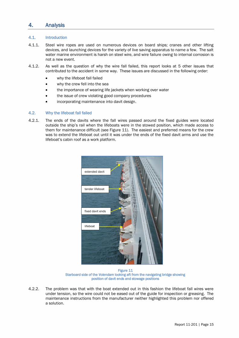
4.2.1. The ends of the davits where the fall wires passed around the fixed guides were located
outside the ship‟s rail when the lifeboats were in the stowed position, which made access to
them for maintenance difficult (see Figure 11). The easiest and preferred means for the crew
was to extend the lifeboat out until it was under the ends of the fixed davit arms and use the
lifeboat‟s cabin roof as a work platform.
Figure 11
Starboard side of the Volendam looking aft from the navigating bridge showing position of davit ends and stowage positions
4.2.2. The problem was that with the boat extended out in this fashion the lifeboat fall wires were
under tension, so the wire could not be eased out of the guide for inspection or greasing. The
maintenance instructions from the manufacturer neither highlighted this problem nor offered
a solution.
fixed davit ends
tender lifeboat
lifeboat
extended davit

Page 16 | Report 11-201
4.2.3. Judging by the condition of the wire where it failed, and the condition of the wire falls at the
same location on the other lifeboats, these sections of the lifeboat wires where they passed
around the fixed guides had not been inspected or lubricated, with the exception of the grease
that was applied to the outside of the wire where it was visible within the guides, for over 4
years in this case. .
4.2.4. Salt-laden water was then easily able to penetrate the core of the wire from the inside of the
guide, and in the absence of lubricant the corrosion process accelerated. The fall wire failed
when the corrosion weakened it to a point where it could no longer support the weight of the
lifeboat. The wire failed in tension overload.
4.2.5. The state of the failed wire and other wires on the remaining boats would have been evident
had a thorough inspection been made. The Commission is surprised that successive
“thorough” inspections by the ship‟s crew and by the manufacturer‟s representatives only 5
months before the accident, had not recognised the potential danger in not inspecting the
complete wire. A wire is only as good as its weakest part, which is why seamen are trained to
inspect all parts of a wire thoroughly during maintenance and annual “thorough inspections”.
4.2.6. Most lifeboat installations have standing parts that can be difficult to inspect or to which it is
difficult to apply grease. Apart from releasing the wire tension to enable proper inspection,
there are other methods of mitigating the risk. It used to be a requirement to end-for-end
lifeboat falls so that at-risk parts of the wire were located elsewhere in the rigging. This is still
a voluntary option but is more difficult to achieve. Some operators opt to start with longer
wires and progressively shorten them during the 4 to 5 year lifespan of the wires. This
achieves the same result for less effort, moving the prone sections of wire to another location
where they can be inspected and lubricated. The design of the lifeboat davit and associated
equipment facilitated a thorough inspection and greasing of the complete wire, but the routine
operation for inspecting and greasing the lifeboat falls on the Volendam did not make best use
of the equipment provided by the manufacturer which would have allowed the weight of the
lifeboat to be taken off of the wire.
4.3. Why the crew members fell into the sea
4.3.1. The failure of the wire and the sudden dropping of the lifeboat bow left little opportunity for the
crew to hold on, so they were totally reliant on their safety harnesses. Both crew members
who fell into the water were wearing the correct safety harnesses and lanyards. They had
strung what should under normal circumstances have been an adequate safety line between
the lifeboat forward and aft suspension hooks. These hooks were of sturdy construction and
were arguably the strongest points on the lifeboat.
4.3.2. The safety line was sufficient in strength and length, having been tied taut between the
suspension hooks. The safety line would have been adequate to take the load should one or
both of the crew members have slipped and fallen.
Findings
The wire rope lifeboat fall failed owing to corrosion of the internal wire strands, brought about
by a lack of lubrication of the standing part of the wire where it passed around the guide near
the terminus of the fall.
The section of wire that failed had not been thoroughly inspected or adequately lubricated
during the 4 years it had been in service.
The design of the lifeboat davit and associated equipment facilitated a thorough inspection
and greasing of the complete wire, but the routine operation for inspecting and greasing the
lifeboat falls on the Volendam had not made best use of the equipment provided by the
manufacturer, which would have allowed the weight of the lifeboat to be taken off the wire.
Report 11-201 | Page 17
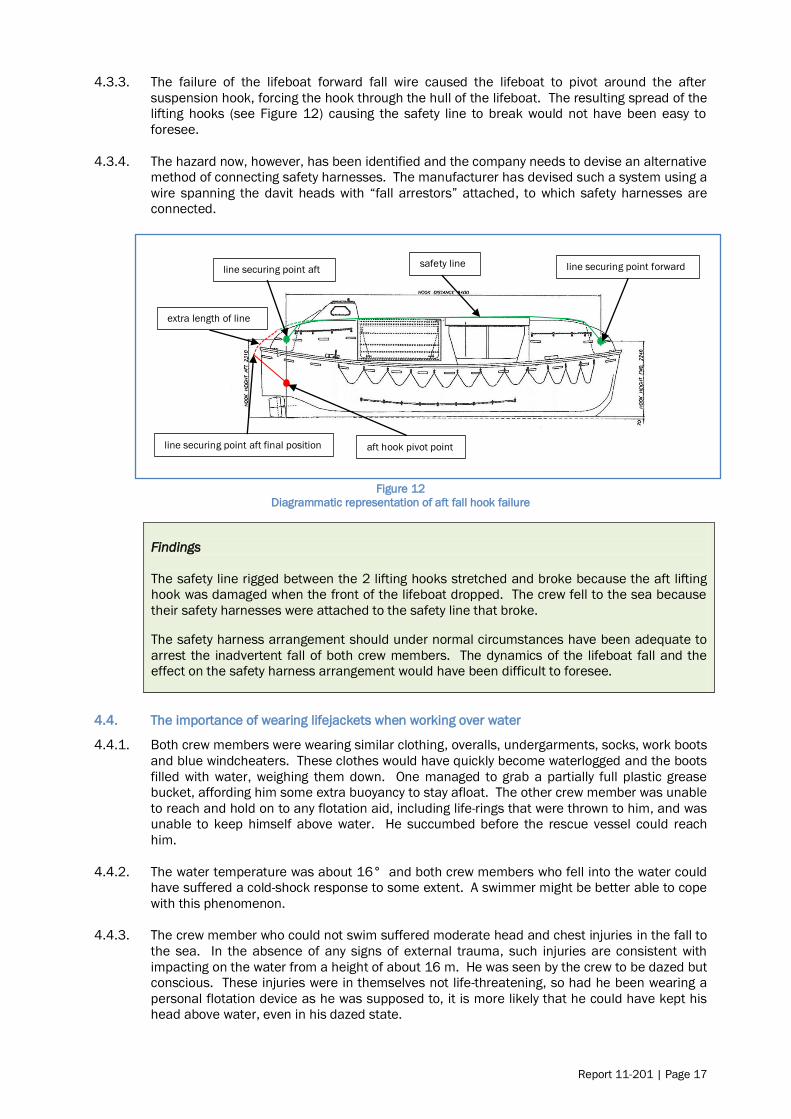
4.3.3. The failure of the lifeboat forward fall wire caused the lifeboat to pivot around the after
suspension hook, forcing the hook through the hull of the lifeboat. The resulting spread of the
lifting hooks (see Figure 12) causing the safety line to break would not have been easy to
foresee.
4.3.4. The hazard now, however, has been identified and the company needs to devise an alternative
method of connecting safety harnesses. The manufacturer has devised such a system using a
wire spanning the davit heads with “fall arrestors” attached, to which safety harnesses are
connected.
Figure 12
Diagrammatic representation of aft fall hook failure
Findings
The safety line rigged between the 2 lifting hooks stretched and broke because the aft lifting
hook was damaged when the front of the lifeboat dropped. The crew fell to the sea because
their safety harnesses were attached to the safety line that broke.
The safety harness arrangement should under normal circumstances have been adequate to
arrest the inadvertent fall of both crew members. The dynamics of the lifeboat fall and the
effect on the safety harness arrangement would have been difficult to foresee.
4.4. The importance of wearing lifejackets when working over water
4.4.1. Both crew members were wearing similar clothing, overalls, undergarments, socks, work boots
and blue windcheaters. These clothes would have quickly become waterlogged and the boots
filled with water, weighing them down. One managed to grab a partially full plastic grease
bucket, affording him some extra buoyancy to stay afloat. The other crew member was unable
to reach and hold on to any flotation aid, including life-rings that were thrown to him, and was
unable to keep himself above water. He succumbed before the rescue vessel could reach
him.
4.4.2. The water temperature was about 16° and both crew members who fell into the water could
have suffered a cold-shock response to some extent. A swimmer might be better able to cope
with this phenomenon.
4.4.3. The crew member who could not swim suffered moderate head and chest injuries in the fall to
the sea. In the absence of any signs of external trauma, such injuries are consistent with
impacting on the water from a height of about 16 m. He was seen by the crew to be dazed but
conscious. These injuries were in themselves not life-threatening, so had he been wearing a
personal flotation device as he was supposed to, it is more likely that he could have kept his
head above water, even in his dazed state.
line securing point aft line securing point forward
line securing point aft final position aft hook pivot point
safety line
extra length of line

Page 18 | Report 11-201
4.4.4. It is a matter of speculation whether all of the factors mentioned above contributed to the
crew member drowning. One thing that can be said with certainty is that if the deceased had
been wearing a personal buoyancy aid his chances of survival would have markedly increased.
Findings
Neither of the crew members who fell into the water was wearing any form of personal
flotation device. A personal flotation device would have increased the chance of the second
crew member surviving.
The second crew member‟s ability to stay afloat was compromised by his inability to swim, the
possibility of cold shock and his dazed state brought on by the injuries he received during the
fall, none of which should have been life-threatening had he been wearing a personal flotation
device.
4.5. Violation of good company procedures
4.5.1. The safety management system of HAL included a policy and procedures document that
applied to all marine operations of HAL. MR600 formed part of this system. Although the
system as a whole was robust and comprised checks and balances throughout to mitigate
chances of error, the crew did not follow it on this occasion.
4.5.2. The crew not following MR600 is considered a violation, which has been described as “a
deliberate deviation from an organisation‟s safety procedures that have been drawn up for the
safe or efficient operation and maintenance of plant or equipment” (Health and Safety
Executive UK, 1995). “Even though violations are deliberate breaches, many of them are
conducted with good intentions to assist the organisation to meet its objectives for example
…” (Mason, 1997). Violations typically reflect a social/motivational phenomenon rather than
an information processing problem.
4.5.3. In this case the non-wearing of personal flotation devices appeared to be an exceptional
violation. “Exceptional violations appear as isolated departures from authority, not necessarily
indicative of individuals‟ typical behaviour pattern nor condoned by management” (Reason,
1990). They are not considered exceptional because of their extreme nature; rather they are
considered exceptional because they are neither typical of the individuals nor condoned by
authority. What makes exceptional violations particularly difficult for an organisation to deal
with is that they are not indicative of individuals‟ behavioural repertoire and, as such, are
particularly difficult to predict. Usually when individuals are confronted with evidence of their
behaviour and asked to explain it, they are left with little explanation (Shappell & Wiegmann,
2000). This was not dissimilar to the surviving crew member on the Volendam when
interviewed after the event; he was aware that they should have been wearing lifejackets but
was at a loss to explain why they were not.
4.5.4. MR600 complied with the documentation for the requirements for workplace safety under De
Arbeidsomstandighedenwet 1996 (Dutch law), Bahamian law, ISM and company policy. It
included sections on accident prevention, occupational workplace safety training, JHA and
work procedures and systems. The JHA section included the responsibilities for crew
members, supervisors and overall programme monitoring. The sections on the fall protection
programme and the use of personal flotation devices included 4 references to working over
the side of the ship and at heights and the need for personal flotation devices and working
aloft permits.
4.5.5. Although MR600 included references to the use of life jackets or personal flotation devices,
the JHA sheets were not clear on the requirement. The JHA sheet for working aloft and
outboard contained a reference to a work vest (see Appendix 3). This work vest was one of
the 5 types of personal flotation devices mentioned in MR600; however, the ambiguity in the
wording between the documents could cause confusion especially to a crew member not
fluent in English. This is an improvement that could be made to the JHA sheets.

Report 11-201 | Page 19
Notwithstanding this point, the crew were familiar with the task and knew that they were
supposed to wear work vests (personal flotation devices).
4.5.6. JHA sheets 0001 and 0009 clearly identified the correct personal protective equipment to be
used and the permits required (see appendices 3 and 4). A correct working aloft permit was
completed as required for the correct day, time and area of operation (see appendix 5). The
JHA‟s also direct personnel to consult both MR 600 and the relevant chapter in the Code of
Safe Working Practices consolidated edition 2007 as published by the United Kingdom
Stationery Office. There was therefore more than sufficient reference to the need to wear
personal flotation devices when working outboard, regardless of whether safety harnesses
were being worn or not.
4.5.7. The safety system included a verbal JHA or “toolbox discussion” before work commenced.
MR600 covered this in section 3.6:
Verbal JHAs are also referred to as pre-job or “tool box” discussions. They are
intended to get crew members focused on the job that they are about to perform.
The greatest benefit comes from the crew member identifying the steps of the
job, recognizing the potential hazards, and planning to eliminate or reduce those
hazards. It is important that supervisors ensure and encourage active
participation from the crew and resist the temptation to merely inform them
about the tasks that they are about to perform. Of course, if a potential hazard is overlooked by the crew members it should be pointed out by the supervisor.
The toolbox discussion that was said to have taken place on 8 January before the wire
greasing took place, if it took place at all, was ineffective at least. Certain features about the
completion of the Toolbox Discussion form (see Appendix 6) that was given to the Commission
after the accident were noted in that:
the date had been manually amended to the correct date of 8 January 2011; this may
have been a typographical error or an omission to change the date from the previous
day, before printing the form
the job description noted that the job was to continue greasing the PS [port side]
lifeboat travelling wires not the starboard side. This could be a similar omission as
noted above
the form did note that a permit was available and that JHA‟s were available and a
potential hazard was falling in the water
the form did note that gloves, signs and barriers, and heavy lift precautions should be
utilised; however
the form did not note that hard hats, boots, harnesses and personal flotation devices
should be used
although the form was initialled by the crew members it was not initialled or signed by
the supervisor to indicate that the “discussion” had taken place, or that the PPE usage
had been verified.
The Commission considers it unlikely that a proper tool box discussion took place. If the
discussion did not take place, the supervisor would probably not have checked the usage of
the PPE. This possibility is further supported by the crew members‟ different recollection of
who the supervisor was; one believing it was the third officer, who was off duty and resting at
the time.
4.5.8. Had the supervisor checked the usage of the PPE the lack of personal flotation devices should
have been apparent. Nevertheless, the purpose of the toolbox discussion was for the crew
members to recognise the potential hazards, and plan to eliminate or reduce those hazards.
The crew members had carried out this task before. They should have had this toolbox
discussion on each occasion and been able to identify for themselves the correct PPE, and the
need for personal flotation devices.

Page 20 | Report 11-201
Findings
The safety management system on board the Volendam and the subsidiary JHA made for the
task of greasing the lifeboat wires were robust and if followed by the crew on the day would
have helped to prevent the death of the crew member when the lifeboat fall failed.
A proper toolbox discussion prior to starting the task for the day probably did not take place,
which was a lost opportunity to ensure that crew conducting the task wore buoyancy aids.
The crew members conducting the task were aware that they were supposed to wear
buoyancy aids when working outside the rail, and regardless of whether a toolbox discussion
took place or not, must bear some responsibility for not complying with the instruction.
4.6. Design and maintenance of the lifeboat launching davit
4.6.1. The design of an installation is more than just the mechanics that make it work. The systems
and procedures for maintaining it in good order form part of the design as well.
4.6.2. The design of a lifeboat davit is often a compromise between efficient functioning and ease of
maintenance. The lifeboat davit manufacturer designs a davit that must receive several
different lifeboat designs, as well as fit many different ship designs. Passenger ships are
usually slab-sided with the lifeboats housed in purpose-built recesses, just like on the
Volendam.
4.6.3. Inevitably there will be parts of a lifeboat davit exposed to the elements, even one that is
housed within a recess. The ends of the fixed arms of the Volendam‟s davits, where the fall
wires passed around the fixed guides were an example of that. The davit ends protruded
outside the rail of the ship, were high up and were therefore difficult to access.
4.6.4. The manufacturer provided equipment to enable most parts of the davit to be inspected and
serviced, but none of these arrangements enabled a thorough inspection of the wire where it
passed around the fixed guides. The crew could access the area by standing on the roof of
the lifeboat with it telescoped out, but could not release the tension on the wire to allow it to
be prised out of the guides for inspection and lubrication. A method was provided for
releasing the tension on the wires, but not when the lifeboat was telescoped out to provide a
work platform.
4.6.5. Ironically, the manufacturer had provided a device that could have achieved both access and
release of wire tension, but this device was designed for a different purpose: to retract the
boats further inboard so that the ship could transit the Panama Canal. Consequently the
process was not documented as one to be used for maintenance, and was not used as such
on board the Volendam.
4.6.6. The maximum lifetime of the wire falls was 5 years, reduced to 4 years by the operator. Four
years was too long for part of a wire to go without lubrication and without inspection. This
should have been obvious to those maintaining and inspecting the wire, including the
manufacturer‟s technicians who conducted the annual “thorough” inspection. The crew
diligently applied grease to the visible part of the wire where it went around the fixed guides,
which would have given the appearance of a well maintained wire, masking the corrosion that
was happening within.
4.6.7. There were options to address the problem. A system of hanging the lifeboat off the trolley in
a similar manner to the Panama Canal link would have been one option, and this is now
offered and recommended by the manufacturer in response to this accident.
4.6.8. Other options would have been to shorten the wire periodically by pulling it through so that a
different section of wire was enclosed in the fixed guides, to use stainless steel wire, and to
install grease nipples within the fixed guides. There are no doubt other solutions to the

Report 11-201 | Page 21
problem, such as accessing the davit ends from the wharf with the aid of a shore based boom
lift or “cherry picker”, as was done during the post-accident inspection of the remaining davits.
4.6.9. The inspection of the davit systems after the accident showed that the design of the davits for
the lifeboats was different from that of the davits for the rescue boats and tender lifeboats.
When the weight of the lifeboat was taken by these davits, an inward elastic deformation of
the fixed arm towards the trolley beam was noted. Over time this inward elastic deformation
when under load had caused a plastic deformation of between 5 mm and 15 mm towards the
trolley beam.
4.6.10. The trolley beam had a vertical face plate at the outer end fixed by 2 triangular metal
brackets; the plastic deformation in the fixed arm could cause the triangular metal brackets to
rub against the fall wire guides on the fixed arm. If for whatever reason the wire rather than
the guide made contact with the triangular brackets, the applied protective coating could be
worn away, allowing the ingress of water or in extreme cases wearing the fall wire itself.
4.6.11. The trolley beam ran in and out on rollers fitted into guides on the fixed arm. The trolley beam
top bar also ran on horizontal and vertical grease-impregnated nylon bearing pads fitted to the
fixed arms. Wear in the vertical pads would allow the trolley beam to move within the fixed
arms and increase the chances of the triangular metal brackets contacting the fall wire guide
and fall wire.
4.6.12. The deformation of the fixed davit arms under load may or may not have contributed to this
wire failure. If the resulting contact between the vertical bracket and the wire had not
damaged the wire, it could at least have scraped the protecting grease from the wire, thus
accelerating the ingress of water and internal corrosion. This was observed to be the case
with number 5 davit.
4.6.13. The manufacturer has alerted ship owners to the potential problem and offered a modification
to address it (see response to safety recommendations).
Findings
The design of the lifeboat davit did not allow easy maintenance of the wire fall where it passed
around the guides on the end of the fixed davit arm, and this problem had gone unnoticed or
ignored during the 10-year life of the vessel.
The fixed arm of the lifeboat davits bending in and contacting the movable trolley had the
potential to contribute, and may have contributed to the wire failure.

Page 22 | Report 11-201
5. Findings
5.1. The wire rope lifeboat fall failed owing to corrosion of the internal wire strands, brought about
by a lack of lubrication of the standing part of the wire where it passed around the guide near
the terminus of the fall.
5.2. The section of wire that failed had not been thoroughly inspected or adequately lubricated
during the 4 years it had been in service.
5.3. The design of the lifeboat davit and associated equipment facilitated a thorough inspection
and greasing of the complete wire, but the routine operation for inspecting and greasing the
lifeboat falls on the Volendam had not made best use of the equipment provided by the
manufacturer, which would have allowed the weight of the lifeboat to be taken off of the wire.
5.4. The safety line rigged between the 2 lifting hooks stretched and broke because the aft lifting
hook was damaged when the front of the lifeboat dropped. The crew fell to the sea because
their safety harnesses were attached to the safety line that broke
5.5. The safety harness arrangement should under normal circumstances have been adequate to
arrest the inadvertent fall of both crew members. The dynamics of the lifeboat fall and the
effect on the safety harness arrangement would have been difficult to foresee.
5.6. Neither of the crew members who fell into the water was wearing any form of personal flotation
device. A personal flotation device would have increased the chance of the second crew
member surviving.
5.7. The second crew member‟s ability to stay afloat was compromised by his inability to swim, the
possibility of cold shock and his dazed state brought on by the injuries he received during the
fall, none of which should have been life-threatening had he been wearing a personal flotation
device.
5.8. The safety management system on board the Volendam and the subsidiary JHA made for the
task of greasing the lifeboat wires were robust and if followed by the crew on the day would
have helped to prevent the death of the crew member when the lifeboat fall failed.
5.9. A proper toolbox discussion prior to starting the task for the day probably did not take place,
which was a lost opportunity to ensure that crew conducting the task wore buoyancy aids.
5.10. The crew members conducting the task were aware that they were supposed to wear buoyancy
aids when working outside the rail, and regardless of whether a toolbox discussion took place
or not, must bear some responsibility for not complying with the instruction.
5.11. The design of the lifeboat davit did not allow easy maintenance of the wire fall where it passed
around the guides on the end of the fixed davit arm, and this problem had gone unnoticed or
ignored during the 10-year life of the vessel.
5.12. The fixed arm of the lifeboat davits bending in and contacting the movable trolley had the
potential to contribute, and may have contributed to the wire failure.
Report 11-201 | Page 23
6. Safety actions
6.1. The Commission classifies safety actions by 2 types:
(a) safety actions taken by the regulator or an operator to address safety issues
identified by the Commission during an inquiry that would otherwise result in the
Commission issuing a recommendation; and
(b) safety actions taken by the regulator or an operator to address other safety
issues that would not normally result in the Commission issuing a
recommendation.
Safety actions addressing safety issues identified during an inquiry
6.2. On 11 January 2011, Holland America Line‟s Fleet Operations issued a Fleet Alert: FA 002-
11 on the subject of lifeboat davit systems – one time inspection, the purpose of which
was to:
conduct a one-time inspection of all lifeboat davit systems, verify that hoisting
wire falls are in proper condition, reiterate fall protection procedures and the use
of personal protective equipment
6.3. On 18 January 2011, Carnival Corporation & PLC (the parent company of Holland America
Line) issued an advisory notice No. 02/2011 which recommended to each of its subsidiary
cruise lines that they:
1. Inspect all lifeboat, tender and rescue boat wire falls for any
abnormalities (fish hooks, corrosion, cuts, abrasion etc) with particular
attention to areas where the wires may be subject to friction against
fixed or moving structural components of the hoisting systems.
2. Examine all sheaves, guides, links, hooks, thimbles and wire securing
points of the hoisting system for any abnormalities such as corrosion
and excessive wear and to ensure proper functionality. During such
inspections the hoisting system should be moved in various positions
as designed.
3. Review its policies and procedures covering working aloft to assess
their adequacy, with particular emphasis to the use and maintenance
of fall prevention devices and the related training provided to
shipboard personnel.
4. Assess the adequacy of its requirements for the use of personal
flotation devices applicable to personnel working over the ship side
and reiterate the importance of using such devices to line workers
and their supervisors.
6.4. On 17 March 2011 the Chief Executive of Navalimpianti Tecnimpianti Group advised the
Commission that:
(a) presently our company is offering to the owners of vessels fitted with our davit
systems the following safety equipment.
1) A safety stainless steel span wire on which the personnel involved in the
inspections or maintenance operations can hook the specific individual safety
device.
2) Two additional eyes, one for each of trolley beams, to which the boat can be
fastened by means of a short lifting fiber lines during the inspection and
maintenance operations. These pad eyes already exist on all tender davits for the
pendant recovery strops. Using these existing devices as a safety means for
inspections and maintenance operations, it is only necessary to hang the boat to
these lifting eyes by two shorter strops, in way to reduce the free falling height to
some centimeters only.

Page 24 | Report 11-201
3) We have also received information of another wire rope failure in an older davit
type due to corrosion on a running wire rope section. The relevant investigation
pointed out that the wire rope was greased after the corrosion began and
consequently the routine visual inspections of the rope did not notice this
corrosion.
After the failure, the wire rope was cleaned, discovering the true status of the
corrosion. For this reason we recommend, that to improve the reliability of the
inspection and maintenance operations a check of the wire rope lengths that
remain for long periods inside the davit arms and pulley boxes with magnetic
instrumentation.
This check may be scheduled with a frequency of 6 or 12 months and, for
example, for a complex telescopic davit may require approximately half day. Our
Company can perform these checks which in conjunction with the existing
computerized instrumentation can show all broken wires and also the reduction of
the rope section due to the corrosion status.
6.5. On 28 September 2011 Holland America Line, in response to the draft final report noted
that the following actions were being taken in response to the accident.
the davit end supporting brackets on the Volendam and Zaandam were being upgraded to mitigate the risk of deflection in service
lifeboat davit wire falls older than 24 months were being replaced with follow up replacements within 36 months
re-emphasis of Holland America Line‟s fall protection programme for
shipboard personnel
re-assessment of Holland America Line‟s work-at-height risks and the putting
in place of a programme of further training of shipboard personnel involved
in working at heights
the issuing of all sailors with appropriate work vests (buoyancy aids)
development of wire and davit maintenance greasing plans for the various types of davits to include diagrams of the davits and hoisting wire and
travelling wire layouts on the davits to ensure 100% of the wire lengths and
davit greasing points are greased
a review to ensure that all wire specifications listed in Holland America Line‟s
database reflect the specifications provided by Navalimpianti and to ensure
that no wires can be ordered from any other vendors and a system is in
place to monitor wire age, and
a swimming lesson programme has been started at Holland America Line‟s
training school in Indonesia

Report 11-201 | Page 25
7. Recommendations
General
7.1. The Commission may issue, or give notice of recommendations to any person or organisation
that it considers the most appropriate to address the identified safety issues, depending on
whether these safety issues are applicable to a single operator only or to the wider transport
sector. In this case, recommendations have been issued to the Navalimpianti Tecnimpianti
Group, with notice of these recommendations given to the Dutch Safety Board, the
International Association of Classification Societies, the Cruise Lines International Association,
and Maritime New Zealand.
7.2. In the interests of transport safety it is important that these recommendations are
implemented without delay to help prevent similar accidents or incidents occurring in the
future.
Recommendations
7.3. On 23 February 2011 in the interim factual report, the Commission made the following
recommendations to the Vice President of the Navalimpianti Tecnimpianti Group.
7.4. The Commission believes it is a safety issue that the design of the SPTDL-150P lifeboat davit
does not facilitate a thorough examination or effective lubrication of the standing part of the
wire falls where they pass around the fixed guides before terminating. Lack of effective
lubrication in this area will promote rapid corrosion and possible premature failure of the wire
rope fall. Difficulty in conducting a thorough examination of the wire rope in this area could
result in the risk of possible premature failure of the wire rope going undetected.
7.5. The Commission believes it is a further safety issue that the design of the SPTDL-150P davit
allows the outer ends of the fixed arm to flex towards the adjacent moving trolley beam when
the load is taken by the wire falls. There is evidence that this flexing can cause the trolley
beam structure to contact the wire guides, and possibly the wire falls, which could lead to
excessive wear and premature failure of the wire rope.
Recommendation 1
It is recommended that as a matter of urgency, the Navalimpianti Tecnimpianti Group alert all
owners of vessels fitted with the SPTDL-150P stored-power telescopic lifeboat davits of the
circumstances of this accident and issue instructions on what immediate inspections and
maintenance should be carried out to prevent a failure of wire rope falls for the same or
similar reasons. (009/11)
Recommendation 2
It is recommended that as a matter of urgency, the Navalimpianti Tecnimpianti Group make a
technical assessment of other lifeboat davit models it has produced to identify if similar safety
issues exist with those models, and if so, alert owners of those davits and issue them with
instructions on what immediate inspections and maintenance should be carried out to prevent
a failure of wire rope falls for the same or similar reasons. (010/11)
Recommendation 3
It is recommended that as a matter of urgency, the Navalimpianti Tecnimpianti Group review
the design of the SPTDL-150P lifeboat davit system with a view to remedying the tendency in
this case for the fixed davit arm to flex inwards under load and contact moving parts of the
structure, which could lead to premature failure of components within the system. (011/11)

Page 26 | Report 11-201
7.6. On 17 March 2011 the Chief Executive of Navalimpianti Tecnimpianti Group replied to the
safety recommendations, a summary of which is included here:
Recommendation 1
We have issued a service bulletin to all owners highlighting critical aspects
for the maintenance of the wire ropes. [see Appendix 1]
Recommendation 2
We are in the process of assessing all our other davit models to identify if
similar safety issues exist with those models and if so we will issue them with instructions on what is required.
Recommendation 3
Regarding the deflection of the fixed davit arm, we have proposed the
addition of a strong steel connection illustrated on the enclosed drawing
[see Appendix 2]. This solution has the advantage that it can be installed on board without dismantling the inner telescopic beams of the davit arm.
Before finalising this modification to the existing davits it will first need to
be approved by the relevant Classification Societies.

Report 11-201 | Page 27
8. Key lessons
8.1. A wire rope is only as good as its weakest part. Unless an inspection covers the entire length
of the wire, a thorough inspection has not been made.
8.2. Wire ropes in a marine environment require frequent and thorough lubrication to prevent
corrosion; otherwise other measures will need to be taken to prevent premature failure of the
wire ropes.
8.3. When selecting a securing point for a safety harness, consideration should be given to its
vulnerability in the event of other catastrophic failures.
8.4. A personal buoyancy device should always be worn when working outside of a ship‟s rail.
8.5. Robust job hazard analysis can prevent injuries and save lives, but only if the procedures that
result are then followed by the crew.

Page 28 | Report 11-201
9. Citations
Health and Safety Executive UK. (1995). Improving compliance with safety procedures. London: HSE
Books.
Mason, S. (1997). Human factors in safety-critical systems. Oxford: Butterworth.
Reason, J. (1990). Human error. New York: Cambridge University Press.
Shappell, S. A., & Wiegmann, D. A. (2000). The human factors analysis and classification system -
HFACS. Washington D.C.: Office of aviation medicine.
Steinman A, G. G. (2001). Cold water immersion. In G. G. Steinman A, & A. P. (Ed.), Wilderness Medicine
4th edition. St. Louis: C.V. Mosby.
United Kingdom Hydrographic Office. (2007). Admiralty Sailing Directions, New Zealand Pilot, NP51.
Taunton, United Kingdom: United Kingdom Hydrographic
Office.
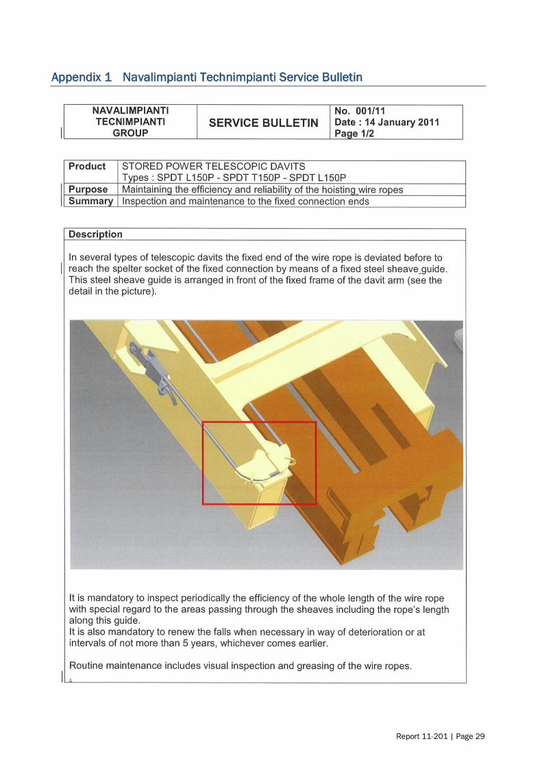
Report 11-201 | Page 29
Appendix 1 Navalimpianti Technimpianti Service Bulletin

Page 30 | Report 11-201

Report 11-201 | Page 31
Appendix 2 Navalimpianti Technimpianti
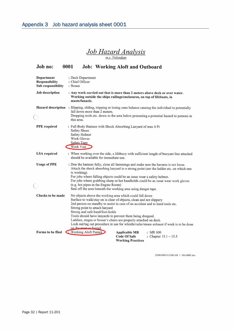
Page 32 | Report 11-201
Appendix 3 Job hazard analysis sheet 0001

Report 11-201 | Page 33
Appendix 4 Job hazard analysis sheet 0009

Page 34 | Report 11-201
Appendix 5 Working aloft permit

Report 11-201 | Page 35
Appendix 6 Toolbox discussion for


Recent Marine Occurrence Reports published by
the Transport Accident Investigation Commission
(most recent at top of list)
11-201, Passenger vessel Volendam, lifeboat fatality,Port of Lyttelton, New Zealand,
8 January 2011
10-203 Marsol Pride, uncontrolled release of fire-extinguishing gas into engine room,
Tui oil and gas field, 27 May 2010
09-204
and 09-207
Coastguard rescue vessel Dive! Tutukaka Rescue collision with rocks,
Taiharuru River entrance Northland, 4 March 2009; Coastguard rescue vessel Trusts
Rescue, heavy weather encounter,Manukau Bar, 31 May 2009
10-201 Bulk carrier TPC Wellington, double fatality resulting from enclosed space entry,
Port Marsden, Northland, 3 May 2010
09-201 Collision: private jet-boat/private watercraft, Kawarau River, Queenstown, 5 January 2009
08-209 Loss of the rigid inflatable boat Mugwop, off the entrance to Lyttelton Harbour, 28
October 2008
11-201 Interim Factual report - Passenger vessel Volendam, lifeboat fatality, port of Lyttelton, New Zealand, 8 January 2011
08-205 Fishing vessel, San Cuvier, dragged anchor and grounded, Tarakeha Point, Bay of
Plenty, 27 July 2008
08-206 Passenger ferry Monte Stello, collisions with wharfs, Picton and Wellington, 8 and 9
August 2008
09-205 Stern trawler Pantas No.1, fatality while working cargo, No.5 berth, Island Harbour, Bluff, 22 April 2009
09-203 Jet boat, DRJS-11 grounding and subsequent rollover Dart River, near Glenorchy, 20
February 2009
08-203 Passenger Ferry Monte Stello, Loss of Power, Tory Channel, 2 May 2008
08-207 Commercial Jet Boat Kawarau Jet No. 6, Roll-Over, confulence of the Kawarau and
Shotover Rivers, 25 September 2008
08-204 6-metre workboat Shikari, collision with moored vessel, Waikawa Bay, Queen
Charlotte Sound, 20 June 2008

Price $38.00 ISSN 1173-5597 (Print)
ISSN 1179-9072 (Online)


