

Minnesota Department of Transportation MEMO Office of Materials Mailstop 645 1400 Gervais Avenue Maplewood, MN 55109 Date: July 31, 2008
To: Robert Evbayekha, Final Design
Waters Edge From: Jeff Narr, Graduate Engineer 1
Geotechnical Engineering Section
Concur: Gary Person, Foundations Engineer Geotechnical Engineering Section
Concur: Rich Lamb, Foundations Project Engineer
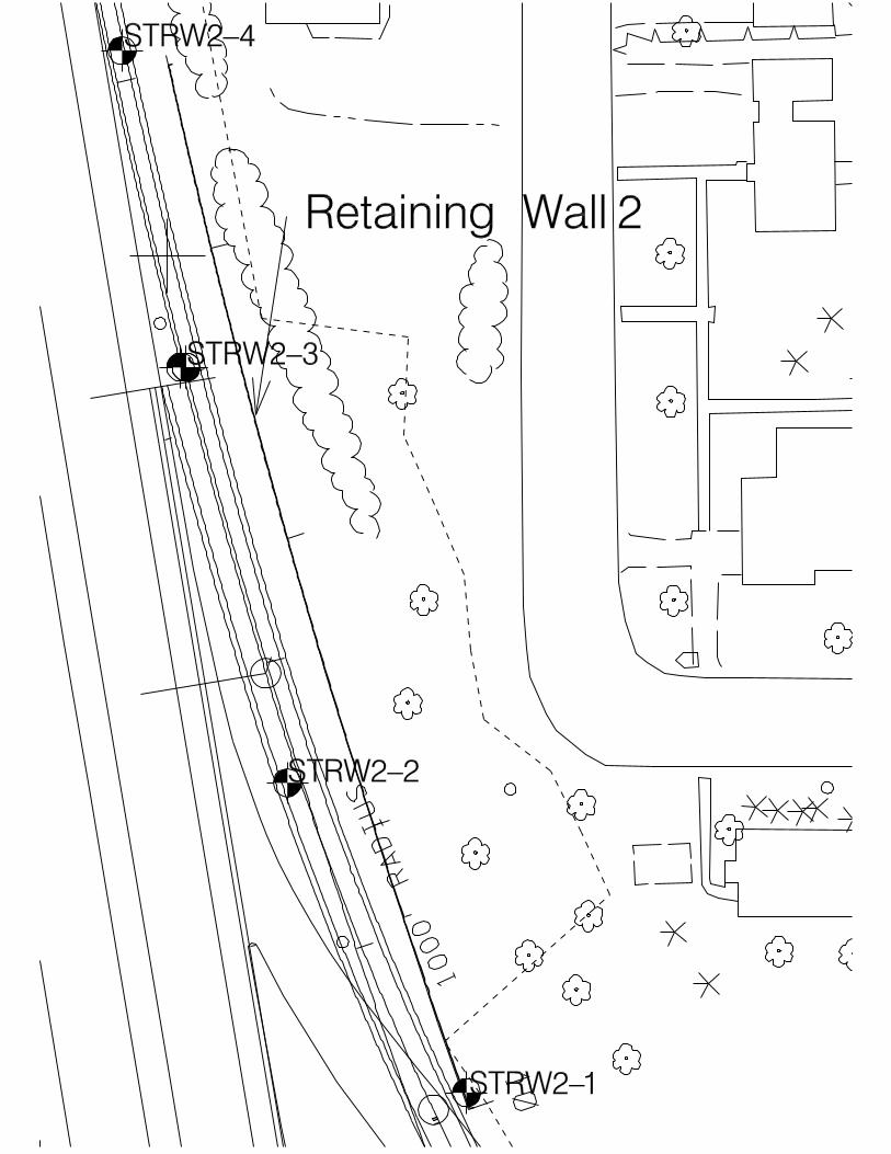
Geotechnical Engineering Section Subject: S.P. 6241-51 TH 280 Retaining Wall 2
Located between Larpenteur Avenue and Broadway Street Foundations Investigation & Recommendations
Project Description This letter provides for a foundation analysis and recommendations for constructing Retaining Wall 2 as part of the Larpenteur Avenue bridge construction in St. Paul. The new wall will be constructed to retain soils on the east side of TH 280 NB. Field Investigation and Foundation Conditions Four foundation borings were taken at this site in May 2008 by Braun Intertec. The foundation soils at the proposed wall location consist of sand and gravel. Please see the attached boring logs for a more detailed description of the foundation soils. Foundation Analysis Existing ground lines, bottom of footing, and top of wall elevations were determined from preliminary plan and profile sheets (see attached wall profile). Spread Footing Bearing Capacity Bearing capacities were calculated for the foundation soils and compared with the required base pressures listed in the Bridge Design Manual for the equivalent retaining wall heights. For this analysis we assumed a 2 ft. live load surcharge loading case. Based on our analysis, the foundation soils from Wall Station 10+00 to 13+60 were determined to have adequate bearing capacities to support the wall. Settlement Wall settlements were calculated based on the bearing pressures listed in Mn/DOT’s Bridge Standard Plans Manual using the retaining wall heights. In addition, our analysis was based on a triangular strip loading stress distribution with the load varying from the maximum toe pressure to zero. The wall will settle a

S.P. 6241-51 TH 280 Ret. Wall 1 Foundations Investigation & Recommendations 7/31/2008
2
maximum of 1 in. at the toe during construction and backfilling operations. In addition, differential settlement from one wall panel to the next should be limited to ½ in. or less. Recommendations Based on the existing conditions along with an analysis of the project soils, we recommend that:
1. Topsoil and other organic material should be removed from areas where fill is to be placed.
2. The wall should be subcut and backfilled according to the attached
Diagram F-1 (Structural Backfill, Footing Subcut & Drainage System Treatment).
3. Footings should be buried a minimum of 4.5 ft. below the final ground
line for frost protection.
4. If the foundation soils found in the field during construction differ from those described in this report, please contact our office for revised foundation recommendations.
Attachments: Boring Logs STRW2-1, STRW2-2, STRW2-3, STRW2-4 (Unique Numbers: 70695 -70698) Boring Plan, Wall Profile, Diagram No. F-1, Boring Index Sheet cc: G. Engstrom D. VanDeusen E. Embacher File
10
10
1000’
RA
DIU
S
STRW2-2
STRW2-1
STRW2-3
STRW2-4
Retaining Wall 2

B1 B2
B3B4
B5B6
1
2
3
4
5
6 7
TOP OF RETAINING WALL
TOP OF FOOTING
BOTTOM OF FOOTING
RETAINING WALL RW2
Coh SPTpl SANDY LOAM, dk
brown, moist, fill
SAND & GRAVEL, w/
moist to dry, dense
moist, meddense
SAND & GRAVEL, brn,
moist, meddense to
dense
moist, meddense to
dense
Bottom of Hole - 31’
No water encountered
or measured during
drilling
Borehole backfilled
48
44
35
36
28
43
27
21
27
19
40
52
STRW2-1 - #70695 - 932.6
890
SAND, w/ a little G, brn,
SAND, w/ a little G, brn,
thin layers of Clay, brn,
Coh SPT 9" of BIT over 9" of
AGG
pl SANDY LOAM, w/G,
dk brn and brn, moist
SAND & GRAVEL, w/
some Bldr, brn, moist,
dense to meddense
SAND, w/G, brn, moist,
dense
Bottom of Hole - 26’
Borehole then
backfilled
37
79
30
16
20
34
34
37
34
33
STRW2-2 - #70696 - 933.1
950
940
930
920
910
900
10+0011+00
12+00
950
940
930
920
910
900

B7
B8
B9 B10
B11
8
9
1011
12
Coh SPT12" of BIT over 8" of
AGG
pl SANDY LOAM, w/G,
dk brn, moist
SAND, w/G and some
Bldr, lt brn, moist,
meddense
SAND & GRAVEL, w/
some Bldr, brn, moist,
meddense
SAND & GRAVEL, w/
some Bldr, brn, moist,
loose to meddense
Auger and sampler
refusal at 27’
Borehole then
backfilled
21
15
28
19
10
15
22
15
25
23
50/.05
STRW2-3 - #70697 - 936.1
INPLACE GROUND
Coh SPT 11" of BIT over 8" of
AGG
F SAND, w/G, w/3" of
Clay Loam, lt brn,
moist, loose, fill
nonpl SANDY LOAM,
w/G, dk brn, moist,
meddense, fill
F SAND, lt brn, moist,
meddense
SAND & GRAVEL w/
some Bldrs, brn, moist,
dense to meddense
Bottom of Hole - 16’
Borehole then
backfilled.
9
20
44
18
54
30
STRW2-4 - #70698 - 937.9
950
940
930
920
910
900
12+00 13+00 14+00

STATE OF MINNESOTA DEPARTMENT OF TRANSPORTATION
STRUCTURAL BACKFILL, FOOTING SUBCUT & DRAINAGE SYSTEM TREATMENT
(STANDARD CANTILEVER RETAINING WALL DESIGN)�PU�PU
PREPARED BY THE FOUNDATIONS UNIT
DIAGRAM NO.
VARIABLE BACKSLOPE
NOT TO SCALE
MINNESOTA
DE
PA
RT
ME
NT OF TRANS
PO
RT
ATIO
N
1A
1B
OR
OR
Weep Hole
2
1.5’
Version
2:1
2:1
All slope dimensions shown as V:H
2:1
F-1
For STANDARD CANTILEVER RETAINING WALLS with water tables at or below the
footing (or pile cap) elevation, the DRAINAGE SYSTEM should consist of one
of the following:
1. A 4" I.D. Non-steel Perforated Pipe (Mn/DOT Spec. 3245) wrapped
A) the top of the footing (or pile cap) and directly
behind the stem of the wall, or
B) the bottom elevation of the footing (or pile cap)
and directly behind the footing (or pile cap)...
completely surrounding the pipe. At all times, the slope of the pipe
should be checked to ensure positive drainage. Frequent ties (spaced
approximately 200 feet apart) should be made from the pipe to the
inplace or proposed drainage system ( subdrain or storm sewer) in the
area. OR
with any modifications as per the attached memorandum.
THE DRAINAGE SYSTEM
with a Type 1 geotextile fabric (Mn/DOT Spec. 3733 ) running the
with structural backfill material (as specified for behind the wall)
entire length of the wall and laid a minimum of 2 in. above...
2. Provide WEEP HOLES as specified in the Bridge Standard Plans Manual,
Standard Sheet No. 5-395.200 to 5-395.205 Wall Reinforcement dated March 14, 1996
2:1 2:
1
1.5’
November 2005
GEOTECHNICAL ENGINEERING SECTION - OFFICE OF MATERIALS
NOTE: THE RECOMMENDATIONS MAY
BE MODIFIED AS PER THE ATTACHED
MEMORANDUM.
IF SUBCUT IS REQUIRED, BACKFILL WITH
GRANULAR BORROW, Mn/DOT SPEC. 3149.2B1
COMPACT BACKFILL TO 100% OF
STANDARD PROCTOR (T-99)
Mn/DOT SPEC. 3149.2B2
MODIFIEDTO 10% PASSING
THE NO. 200 SIEVE COMPACT
BACKFILL TO SPECIFIED
DENSITY METHOD Mn/DOT
SPEC. 2105.3F1
MINIMUM LIMITS OF
WEDGE OF SPECIFIED
BACKFILL MATERIAL
PAY LIMITS FOR STRUCTURAL EXCAVATION
WHEN A SUBCUT IS REQUIRED. ACTUAL
EXCAVATION SLOPE IS DETERMINED BY
OSHA REGULATIONS AND IN-SITU SOILS.
4.5’
FINAL SLOPE TO BE
DETERMINED BY ROAD DESIGN
ANY SUITABLE
BACKFILL MATERIAL
ANY SUITABLE
BACKFILL MATERIAL
Vane Shear Test Washed Sample (Collected during plug drilling)
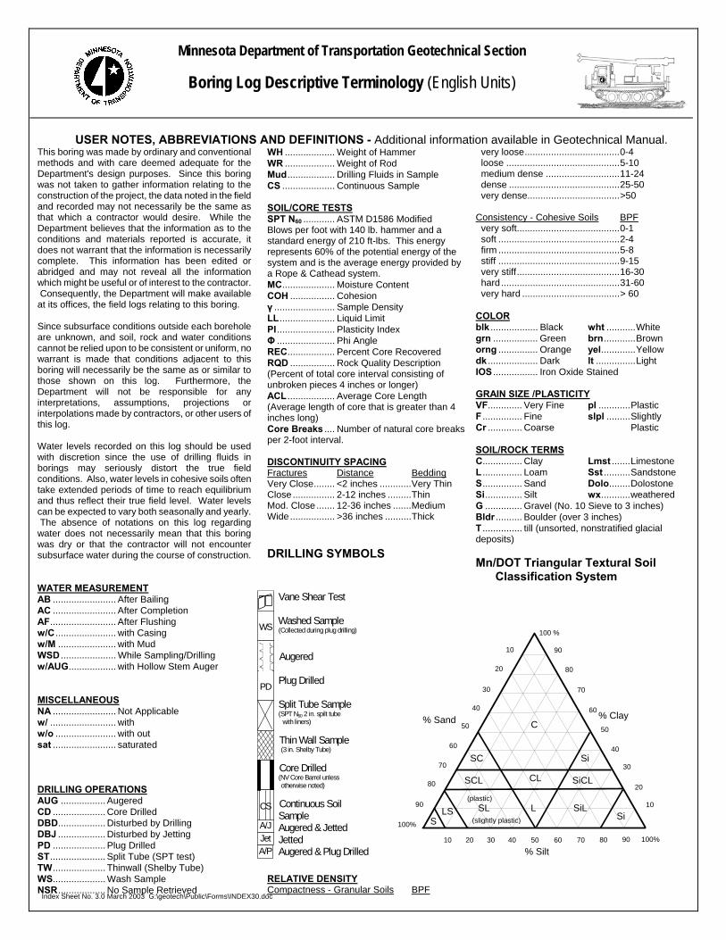
Minnesota Department of Transportation Geotechnical Section
Boring Log Descriptive Terminology (English Units)
USER NOTES, ABBREVIATIONS AND DEFINITIONS - Additional information available in Geotechnical Manual. This boring was made by ordinary and conventional methods and with care deemed adequate for the Department's design purposes. Since this boring was not taken to gather information relating to the construction of the project, the data noted in the field and recorded may not necessarily be the same as that which a contractor would desire. While the Department believes that the information as to the conditions and materials reported is accurate, it does not warrant that the information is necessarily complete. This information has been edited or abridged and may not reveal all the information which might be useful or of interest to the contractor. Consequently, the Department will make available at its offices, the field logs relating to this boring. Since subsurface conditions outside each borehole are unknown, and soil, rock and water conditions cannot be relied upon to be consistent or uniform, no warrant is made that conditions adjacent to this boring will necessarily be the same as or similar to those shown on this log. Furthermore, the Department will not be responsible for any interpretations, assumptions, projections or interpolations made by contractors, or other users of this log. Water levels recorded on this log should be used with discretion since the use of drilling fluids in borings may seriously distort the true field conditions. Also, water levels in cohesive soils often take extended periods of time to reach equilibrium and thus reflect their true field level. Water levels can be expected to vary both seasonally and yearly. The absence of notations on this log regarding water does not necessarily mean that this boring was dry or that the contractor will not encounter subsurface water during the course of construction. WATER MEASUREMENT
Augered Plug Drilled Split Tube Sample (SPT N60 2 in. spilt tube with liners) Thin Wall Sample (3 in. Shelby Tube) Core Drilled (NV Core Barrel unless otherwise noted) Continuous Soil Sample Augered & Jetted Jetted Augered & Plug Drilled
WS
PD
CS
A/J Jet A/P
AB ........................ After Bailing AC ........................ After Completion AF......................... After Flushing w/C ....................... with Casing
Index Sheet No. 3.0 March 2003 G:\geotech\Public\Forms\INDEX30.doc
w/M ...................... with Mud WSD ..................... While Sampling/Drilling w/AUG.................. with Hollow Stem Auger MISCELLANEOUS NA ........................ Not Applicable w/ ......................... with w/o ....................... with out sat ........................ saturated DRILLING OPERATIONS AUG ................. Augered CD .................... Core Drilled DBD.................. Disturbed by Drilling DBJ .................. Disturbed by Jetting PD .................... Plug Drilled ST..................... Split Tube (SPT test) TW.................... Thinwall (Shelby Tube) WS.................... Wash Sample NSR.................. No Sample Retrieved
WH ................... Weight of Hammer WR ................... Weight of Rod Mud.................. Drilling Fluids in Sample CS .................... Continuous Sample SOIL/CORE TESTS SPT N60 ............ ASTM D1586 Modified Blows per foot with 140 lb. hammer and a standard energy of 210 ft-lbs. This energy represents 60% of the potential energy of the system and is the average energy provided by a Rope & Cathead system. MC.................... Moisture Content COH ................. Cohesion γ ....................... Sample Density LL..................... Liquid Limit PI...................... Plasticity Index Φ ...................... Phi Angle REC.................. Percent Core Recovered RQD ................. Rock Quality Description (Percent of total core interval consisting of unbroken pieces 4 inches or longer) ACL .................. Average Core Length (Average length of core that is greater than 4 inches long) Core Breaks .... Number of natural core breaks per 2-foot interval. DISCONTINUITY SPACING Fractures Distance Bedding Very Close........ <2 inches ............Very Thin Close ................ 2-12 inches .........Thin Mod. Close ....... 12-36 inches .......Medium Wide................. >36 inches ..........Thick DRILLING SYMBOLS
RELATIVE DENSITY Compactness - Granular Soils BPF
very loose....................................0-4 loose ...........................................5-10 medium dense ............................11-24 dense ..........................................25-50 very dense...................................>50
Consistency - Cohesive Soils BPF
very soft.......................................0-1 soft ..............................................2-4 firm ..............................................5-8 stiff ..............................................9-15 very stiff.......................................16-30 hard.............................................31-60 very hard .....................................> 60
COLOR blk .................. Black wht ...........White grn ................. Green brn............Brown orng ............... Orange yel.............Yellow dk ................... Dark lt ...............Light IOS ................. Iron Oxide Stained GRAIN SIZE /PLASTICITY VF............. Very Fine pl ............Plastic F ............... Fine slpl .........Slightly Cr ............. Coarse Plastic SOIL/ROCK TERMS C............... Clay Lmst .......Limestone L ............... Loam Sst ..........Sandstone S............... Sand Dolo........Dolostone Si.............. Silt wx...........weathered G .............. Gravel (No. 10 Sieve to 3 inches) Bldr .......... Boulder (over 3 inches) T ............... till (unsorted, nonstratified glacial deposits) Mn/DOT Triangular Textural Soil Classification System
100%
100%
C
90807060 50 40 302010
90
80
70
60
50
40
30
20
10
(plastic)
(slightly plastic)
SC
SCL CL
L SL SiL
Si
SiCL
LSS Si
90
80
70
60
50
40
30
20
10
100 %
% Sand % Clay
% Silt
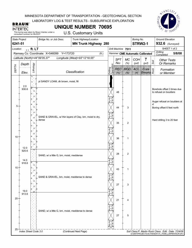
pl SANDY LOAM, dk brown, moist, fill
SAND & GRAVEL, w/ thin layers of Clay, brn, moist to dry,dense
SAND, w/ a little G, brn, moist, meddense
SAND & GRAVEL, brn, moist, meddense to dense
SAND, w/ a little G, brn, moist, meddense to dense
3
2
1
2
1
3
4
5
2.0930.6
12.0920.6
14.0918.6
19.0913.6
48
44
35
36
28
43
27
21
27
, , ft. LT(ft.)
LocationDrilling
SHEET 1 of 2
Ramsey Co. Coordinate: X=546099 Y=1737207511
Longitude (West)=93°12'18.55"CME Automatic Calibrated 5/8/08Completed
Latitude (North)=44°59'35.37"
Drill Machine
Hammer
Ground Elevation
(Surveyed)MN Trunk Highway 280Trunk Highway/Location Boring No.
6241-51State Project Bridge No. or Job Desc.
STRW2-1 932.6
(%)
U.S. Customary Units
5
10
15
20
25
(%) (ft)
(pcf)N60
FormationREC ACL
Soi
l
Dril
ling
Ope
ratio
n
Lith
olog
y
RQD Core
Index Sheet Code 3.0G:\GINT\PROJECTS-ACTIVE\6241-51_TH280_LARPENTEUR.GPJ
Roc
k
DE
PTH
(psf)MC(%)
Classification
Other Tests
This boring was taken by Braun Intertec under aconsultant contract for Mn/DOT
or Member
UNIQUE NUMBER 70695
(Continued Next Page)
DepthCOH
Soil Class:P. Martin Rock Class: Edit: Date: 7/24/08
Breaks
Or Remarks
Elev.
SPT
MINNESOTA DEPARTMENT OF TRANSPORTATION - GEOTECHNICAL SECTIONLABORATORY LOG & TEST RESULTS - SUBSURFACE EXPLORATION
Borehole offset 3 times dueto refusal on boulders
Auger refusal on boulders at4'Boring offset 6 feet north
Hard drilling 3 to 20 feet
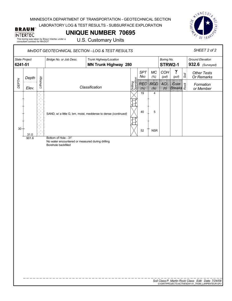
SAND, w/ a little G, brn, moist, meddense to dense (continued)
Bottom of Hole - 31'No water encountered or measured during drillingBorehole backfilled
NSR
4
5
31.0901.6
19
40
52
Ground Elevation
(Surveyed)MN Trunk Highway 280Trunk Highway/Location Boring No.
6241-51State Project Bridge No. or Job Desc.
STRW2-1 932.6
Mn/DOT GEOTECHNICAL SECTION - LOG & TEST RESULTS SHEET 2 of 2
(%)
U.S. Customary Units
30
(%) (ft)
(pcf)N60
FormationREC ACL
Soi
l
Dril
ling
Ope
ratio
n
Lith
olog
y
RQD Core
G:\GINT\PROJECTS-ACTIVE\6241-51_TH280_LARPENTEUR.GPJ
Roc
k
DE
PTH
(psf)MC(%)
Classification
Other Tests
This boring was taken by Braun Intertec under aconsultant contract for Mn/DOT
or Member
UNIQUE NUMBER 70695
DepthCOH
Soil Class:P. Martin Rock Class: Edit: Date: 7/24/08
Breaks
Or Remarks
Elev.
SPT
MINNESOTA DEPARTMENT OF TRANSPORTATION - GEOTECHNICAL SECTIONLABORATORY LOG & TEST RESULTS - SUBSURFACE EXPLORATION

9" of BIT over 9" of AGG
pl SANDY LOAM, w/G, dk brn and brn, moist
SAND & GRAVEL, w/ some Bldr, brn, moist, dense tomeddense
SAND, w/G, brn, moist, dense
1.5931.62.0
931.1
14.0919.1
37
79
30
16
20
34
34
37
34
, , ft. LT(ft.)
LocationDrilling
SHEET 1 of 2
Ramsey Co. Coordinate: X=546040 Y=1738257511
Longitude (West)=93°12'19.38"CME Automatic Calibrated 5/19/08Completed
Latitude (North)=44°59'36.40"
Drill Machine
Hammer
Ground Elevation
(Surveyed)MN Trunk Highway 280Trunk Highway/Location Boring No.
6241-51State Project Bridge No. or Job Desc.
STRW2-2 933.1
(%)
U.S. Customary Units
5
10
15
20
25
(%) (ft)
(pcf)N60
FormationREC ACL
Soi
l
Dril
ling
Ope
ratio
n
Lith
olog
y
RQD Core
Index Sheet Code 3.0G:\GINT\PROJECTS-ACTIVE\6241-51_TH280_LARPENTEUR.GPJ
Roc
k
DE
PTH
(psf)MC(%)
Classification
Other Tests
This boring was taken by Braun Intertec under aconsultant contract for Mn/DOT
or Member
UNIQUE NUMBER 70696
(Continued Next Page)
DepthCOH
Soil Class:P. Martin Rock Class: Edit: Date: 7/24/08
Breaks
Or Remarks
Elev.
SPT
MINNESOTA DEPARTMENT OF TRANSPORTATION - GEOTECHNICAL SECTIONLABORATORY LOG & TEST RESULTS - SUBSURFACE EXPLORATION
Hard drilling surface to 10'depth

SAND, w/G, brn, moist, dense (continued)
Bottom of Hole - 26'Borehole then backfilled
26.0907.1
33
Ground Elevation
(Surveyed)MN Trunk Highway 280Trunk Highway/Location Boring No.
6241-51State Project Bridge No. or Job Desc.
STRW2-2 933.1
Mn/DOT GEOTECHNICAL SECTION - LOG & TEST RESULTS SHEET 2 of 2
(%)
U.S. Customary Units
(%) (ft)
(pcf)N60
FormationREC ACL
Soi
l
Dril
ling
Ope
ratio
n
Lith
olog
y
RQD Core
G:\GINT\PROJECTS-ACTIVE\6241-51_TH280_LARPENTEUR.GPJ
Roc
k
DE
PTH
(psf)MC(%)
Classification
Other Tests
This boring was taken by Braun Intertec under aconsultant contract for Mn/DOT
or Member
UNIQUE NUMBER 70696
DepthCOH
Soil Class:P. Martin Rock Class: Edit: Date: 7/24/08
Breaks
Or Remarks
Elev.
SPT
MINNESOTA DEPARTMENT OF TRANSPORTATION - GEOTECHNICAL SECTIONLABORATORY LOG & TEST RESULTS - SUBSURFACE EXPLORATION
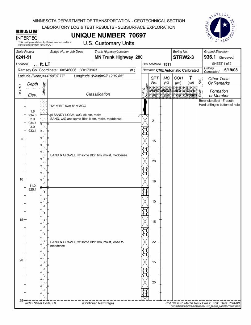
12" of BIT over 8" of AGG
pl SANDY LOAM, w/G, dk brn, moistSAND, w/G and some Bldr, lt brn, moist, meddense
SAND & GRAVEL, w/ some Bldr, brn, moist, meddense
SAND & GRAVEL, w/ some Bldr, brn, moist, loose tomeddense
1.8934.32.0
934.13.0
933.1
11.0925.1
21
15
28
19
10
15
22
15
25
, , ft. LT(ft.)
LocationDrilling
SHEET 1 of 2
Ramsey Co. Coordinate: X=546006 Y=1739637511
Longitude (West)=93°12'19.85"CME Automatic Calibrated 5/19/08Completed
Latitude (North)=44°59'37.77"
Drill Machine
Hammer
Ground Elevation
(Surveyed)MN Trunk Highway 280Trunk Highway/Location Boring No.
6241-51State Project Bridge No. or Job Desc.
STRW2-3 936.1
(%)
U.S. Customary Units
5
10
15
20
25
(%) (ft)
(pcf)N60
FormationREC ACL
Soi
l
Dril
ling
Ope
ratio
n
Lith
olog
y
RQD Core
Index Sheet Code 3.0G:\GINT\PROJECTS-ACTIVE\6241-51_TH280_LARPENTEUR.GPJ
Roc
k
DE
PTH
(psf)MC(%)
Classification
Other Tests
This boring was taken by Braun Intertec under aconsultant contract for Mn/DOT
or Member
UNIQUE NUMBER 70697
(Continued Next Page)
DepthCOH
Soil Class:P. Martin Rock Class: Edit: Date: 7/24/08
Breaks
Or Remarks
Elev.
SPT
MINNESOTA DEPARTMENT OF TRANSPORTATION - GEOTECHNICAL SECTIONLABORATORY LOG & TEST RESULTS - SUBSURFACE EXPLORATION
Borehole offset 15' southHard drilling to bottom of hole

SAND & GRAVEL, w/ some Bldr, brn, moist, loose tomeddense (continued)
Auger and sampler refusal at 27'Borehole then backfilled
27.0909.1
23
50/.05
Ground Elevation
(Surveyed)MN Trunk Highway 280Trunk Highway/Location Boring No.
6241-51State Project Bridge No. or Job Desc.
STRW2-3 936.1
Mn/DOT GEOTECHNICAL SECTION - LOG & TEST RESULTS SHEET 2 of 2
(%)
U.S. Customary Units
(%) (ft)
(pcf)N60
FormationREC ACL
Soi
l
Dril
ling
Ope
ratio
n
Lith
olog
y
RQD Core
G:\GINT\PROJECTS-ACTIVE\6241-51_TH280_LARPENTEUR.GPJ
Roc
k
DE
PTH
(psf)MC(%)
Classification
Other Tests
This boring was taken by Braun Intertec under aconsultant contract for Mn/DOT
or Member
UNIQUE NUMBER 70697
DepthCOH
Soil Class:P. Martin Rock Class: Edit: Date: 7/24/08
Breaks
Or Remarks
Elev.
SPT
MINNESOTA DEPARTMENT OF TRANSPORTATION - GEOTECHNICAL SECTIONLABORATORY LOG & TEST RESULTS - SUBSURFACE EXPLORATION
Auger and sampler refusal at27' . Lead auger broke off,unable to continue.

11" of BIT over 8" of AGG
F SAND, w/G, w/3" of Clay Loam, lt brn, moist, loose, fill
nonpl SANDY LOAM, w/G, dk brn, moist, meddense, fill
F SAND, lt brn, moist, meddense
SAND & GRAVEL w/ some Bldrs, brn, moist, dense tomeddense
Bottom of Hole - 16'Borehole then backfilled.
1.6936.3
4.0933.9
5.5932.46.5
931.4
16.0921.9
9
20
44
18
54
30
, , ft. LT(ft.)
LocationDrilling
SHEET 1 of 1
Ramsey Co. Coordinate: X=545984 Y=1740687511
Longitude (West)=93°12'20.14"CME Automatic Calibrated 5/19/08Completed
Latitude (North)=44°59'38.81"
Drill Machine
Hammer
Ground Elevation
(Surveyed)MN Trunk Highway 280Trunk Highway/Location Boring No.
6241-51State Project Bridge No. or Job Desc.
STRW2-4 937.9
(%)
U.S. Customary Units
5
10
15
(%) (ft)
(pcf)N60
FormationREC ACL
Soi
l
Dril
ling
Ope
ratio
n
Lith
olog
y
RQD Core
Index Sheet Code 3.0G:\GINT\PROJECTS-ACTIVE\6241-51_TH280_LARPENTEUR.GPJ
Roc
k
DE
PTH
(psf)MC(%)
Classification
Other Tests
This boring was taken by Braun Intertec under aconsultant contract for Mn/DOT
or Member
UNIQUE NUMBER 70698
DepthCOH
Soil Class:P. Martin Rock Class: Edit: Date: 7/24/08
Breaks
Or Remarks
Elev.
SPT
MINNESOTA DEPARTMENT OF TRANSPORTATION - GEOTECHNICAL SECTIONLABORATORY LOG & TEST RESULTS - SUBSURFACE EXPLORATION
Hard drilling to bottom of hole
Auger broke off about 5'below surface. Sample rodcut off about 6" belowsurface.


