

ORI GIN AL PA PER
Monitoring systems for warning impending failuresin slopes and open pit mines
Ashkan Vaziri • Larry Moore • Hosam Ali
Received: 21 August 2009 / Accepted: 13 April 2010 / Published online: 1 May 2010� Springer Science+Business Media B.V. 2010
Abstract Slope stability is a critical safety and production issue for mining. Major wall
failure can occur seemingly without any visual warning, causing loss of lives, damage to
equipment, and disruption to the mining process. Monitoring systems, ranging from simple
piezometers and extensometers to highly sophisticated radars and global navigation
satellite systems, are employed to predict impending instabilities and failure. Here, we
provide a review of the available monitoring systems used in slope management and
highlight their major advantages and shortcomings. We propose a simple method for
evaluating the effectiveness and reliability of monitoring systems to warn of pending slope
failures. The method is based on constructing monitoring reliability maps for the slope by
evaluating two slope parameters: Expected deformation to failure and critical reading
frequency, which depend on the slope characteristics (e.g., geology and design), service
condition (e.g., rainfall, blast), and the economic impact of the failure. The reliability of a
deformation monitoring system can be subsequently assessed by identifying three
parameters of the system: Coverage area (large or discrete), Deformation monitoring
precision, and Measurement frequency. The application of the method to most commonly
used deformation monitoring systems is demonstrated. The advantages and implications of
the proposed method are highlighted.
Keywords Mining � Slope stability � Deformation monitoring systems � Safety
1 Introduction
Small precursor movements of slopes can occur for an extended period ranging from weeks
to months prior to instability (Hoek and Bray 1981). Monitoring systems have been used
A. Vaziri � L. Moore � H. AliFM Global, 1151 Boston-Providence Turnpike, Norwood, MA 02062, USA
A. Vaziri (&)Department of Mechanical and Industrial Engineering, Northeastern University,Boston, MA 02115, USAe-mail: [email protected]
123
Nat Hazards (2010) 55:501–512DOI 10.1007/s11069-010-9542-5
Author's personal copy
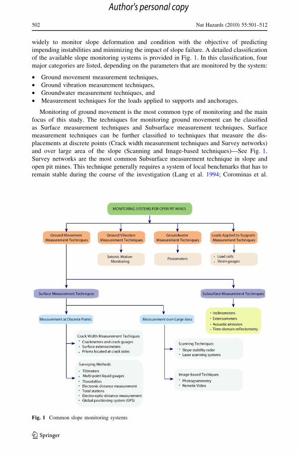
widely to monitor slope deformation and condition with the objective of predicting
impending instabilities and minimizing the impact of slope failure. A detailed classification
of the available slope monitoring systems is provided in Fig. 1. In this classification, four
major categories are listed, depending on the parameters that are monitored by the system:
• Ground movement measurement techniques,
• Ground vibration measurement techniques,
• Groundwater measurement techniques, and
• Measurement techniques for the loads applied to supports and anchorages.
Monitoring of ground movement is the most common type of monitoring and the main
focus of this study. The techniques for monitoring ground movement can be classified
as Surface measurement techniques and Subsurface measurement techniques. Surface
measurement techniques can be further classified to techniques that measure the dis-
placements at discrete points (Crack width measurement techniques and Survey networks)
and over large area of the slope (Scanning and Image-based techniques)—See Fig. 1.
Survey networks are the most common Subsurface measurement technique in slope and
open pit mines. This technique generally requires a system of local benchmarks that has to
remain stable during the course of the investigation (Lang et al. 1994; Corominas et al.
Fig. 1 Common slope monitoring systems
502 Nat Hazards (2010) 55:501–512
123
Author's personal copy

2000). In principle, survey techniques are limited by two main drawbacks. First, they all
require access to the monitoring surface for installation and maintenance of instruments.
Second, these techniques sample a few discrete points on a monitoring surface, thus, fail
to provide spatial information required to assess the behavior of the whole mine wall
(Lichti et al. 2000). Recent advancements in development of precise displacement
measurement techniques have yielded robust and sophisticated devices for slope moni-
toring and mine management. An example is radar systems that progressively scan along
the slope or pit wall taking measurements with a beam at each point. In these systems,
data resolution is a function of the radar operation frequency and the radar distance from
the target. The closer the radar is to the wall, the smaller the beam size (or pixel size) of
the area being measured. In general, these systems are capable of continuous monitoring
movement with high accuracy (0.1–0.2 mm) over medium to large areas in real time
without the need for mounted reflectors or equipment on the slope. Furthermore, the
measurement is minimally affected by rain, dust, or smoke (Reeves et al. 2001; McHugh
et al. 2006; Hutchison and Widelski 2007). The most common devices and methods of
Subsurface displacement measurement are inclinometers, extensometers, acoustic emis-
sion, and time-domain reflectometry. It is noteworthy that some of the techniques
mentioned above, such as time-domain reflectometry, can be used for both surface and
subsurface deformation measurements and are listed in Fig. 1 in view of their most
common application.
Measurement of groundwater pressure, anchorage stresses, and seismic motion can
provide valuable information for detecting impending failures and should be utilized when
appropriate. Piezometers are often used for groundwater pressure monitoring. The most
common types of piezometers are standpipe piezometers, vibrating wire piezometers,
pneumatic piezometers, and multi-point piezometers. In mines located in seismically active
areas, microseismic monitoring is used to detect zones of seismic activity, which can cause
rockbursts and earthquakes, therefore triggering slope failure.
According to Call and Savely (Call and Savely 1990), the most important purpose of a
slope monitoring program is to:
1. Maintain safe operational practices,
2. Provide advance notice of instability, so action can be taken to minimize the impact of
slope displacement, and
3. Provide additional geotechnical information regarding slope behavior.
The selection of a monitoring system should be carried out in view of its reliability and
capabilities, as well as the importance of the slope and its failure impact. This requires
thorough understanding of displacement patterns that result from generally occurring
mechanisms of failure (Lang et al. 1993; Pothitos and Li 2007; Pothitos et al. 2006;
Wilkins et al. 2003). Environmental conditions (e.g., local onshore wind, high temperature
variation, rainfall, insolation and tidal conditions, storm frequency and seismic regions)
should be also rigorously considered when selecting systems for slope monitoring to ensure
their reliability for warning of impending failures.
In this work, we will develop an objective method for evaluating the reliability of the
deformation monitoring systems used in mines and slope management. Section 2 provides
a brief review of the slope displacement patterns and common failure mechanisms. The
key parameters that determine the accuracy and reliability of slope displacement moni-
toring systems are discussed in Sect. 3. In Sect. 4, a reliability map for slope monitoring
systems is proposed in view of the key factors discussed in Sect. 3. Section 5 provides a
conclusive summary of the findings of this study.
Nat Hazards (2010) 55:501–512 503
123
Author's personal copy

2 Slope displacement patterns and failure
The movements that occur prior to collapse can result from multiple phenomena including
elasto-plastic deformation, softening and failure of the rock mass (Sullivan 2007). Zavodni
and Broadbent (1978) showed that almost all large-scale failures occur gradually, with the
exception of slides initiated by earthquake. Serious slope instabilities are usually accom-
panied by the gradual development of tension cracks behind the slope crest and measurable
displacements. Figure 2 shows typical slope displacement histories resulting from creep as
proposed by Fell et al. (2000). The creep response of the slope is differentiated into
Primary (with decreasing strain rate), Secondary (with constant strain rate), and Tertiary
(with increasing strain rate). Tertiary creep is generally followed by failure and collapse of
the slope. During primary creep, the strain rate usually decreases as a power law of the
time. The strain rate during secondary creep is nearly constant and strongly depends on the
applied stress (Amitrano and Helmstetter 2006). Varnes (1982) showed that the secondary
creep generally occurs for a short period, as in this stage both primary and tertiary creep
mechanisms may occur concurrently. In fact, in some cases, a crossover between decaying
primary creep and accelerating tertiary creep is observed with no clear secondary creep
regime (Hamiel et al. 2004). Field measurements indicate that the final phase of failure in
slopes is characterized by a hyperbolic function in the velocity–time space. Petley (2004)
suggested that this behavior mirrors the nonlinear final stage of creep experienced in brittle
failure. If the rate of movement decreases, the slope may have temporarily stabilized as
shown in Fig. 2 by the red curve.
The three most common slope failure modes are circular failure, toppling and planar and
wedge failures (Lang et al. 1993; Forward 2002; Hoek 1973; Sjoberg 1999, 2001; Turner
and Schuster 1996; Dunnicliff 1995; Angeli et al. 2000; Mercer 2006). Each of the failure
modes has certain features, which include the direction in which considerable movements
occur. Circular failure generally occurs in soil, weathered and soft rock, highly fractured
rock and waste dumps. The initial step of instability is usually the opening of tension
cracks along the crest of the slope, followed by slumping of the crest and lateral movement
of the toe. The final failure generally happens rapidly. The failed section size can range
from a few meters in height to several kilometers across. Initial large vertical displace-
ments and small horizontal displacements, which increase with progression of the failure,
are the common features of circular failures. Toppling is common in rocks with
well-defined bedding planes or joints that are extended into the slope. The horizontal
Fig. 2 Creep behavior ofmoving slopes (Fell et al. 2000)
504 Nat Hazards (2010) 55:501–512
123
Author's personal copy

movement associated with this failure mode opens up tension cracks along the crest, while
the movement at the slope toe is generally negligible. Small initial vertical displacements
and large horizontal displacements are the general characteristics of toppling failure.
Turner and Schuster (1996) suggested that this failure mode can be further categorized into
flexural toppling, block toppling, and block flexural toppling. Planar and Wedge failures
are common in hard rock slopes with continuous bedding or joint planes dipping out of the
slope. Since failure generally takes place on a distinct plane, the failed block will move
parallel to this plane and failure is often sudden with little warning. The pattern of failure
may comprise of a single discontinuity plane, two planes that intersect each other (wedge
failure) or a combination of multiple discontinuities that are linked together to form more
complex patterns such as slab failure and step path failure (Sjoberg 1999).
In addition to the common failure modes discussed above, undercutting or raveling of
steep rock faces may also occur in slopes due to toe erosion, particularly if the slope is
made of low-durability rock (Dunnicliff 1995). Combined failure modes can also occur in
weathered materials where the shear strength of the material may be sufficiently low to
allow preferential failure through the material, rather than only along discontinuities (Lang
et al. 1993). Combination of toppling failure at the toe of the failure zone, with circular or
planar sliding failure in the upper part of the failure, has also been recorded. More detailed
descriptions of the slope failure modes and mechanisms, their dependence on the rock
characteristics and also common stages of each failure mode are provided by Sjoberg
(2001).
Most of the displacement monitoring sensors can be hooked to a warning device. In
such cases, the warning is activated when a prescribed amount of displacement,
displacement rate, or acceleration occurs. The difficulty in this procedure is determining
the thresholds, since the critical value corresponding to onset of the failure varies widely
from one mine to another (Angeli et al. 2000; Mercer 2006). This means that an alarm
criterion used at one mine may not be applicable for other mines. In most practical cases,
the threshold velocities used for the warning device represent rates that Mine Engineering
and Operations are comfortable with based on past experience. The current mining con-
ditions and the impact and importance of a particular wall to continue mine production are
also considered when deciding critical movement rates and monitoring plans. For example,
security of haul road access is a prime operating safety and production requirement for
many mines, and thus, the thresholds for walls associated with a haul road should be
chosen with extra caution.
3 Key parameters for reliability of displacement monitoring systems
Three key parameters of displacement monitoring systems are identified which should be
considered in assessments of the reliability of monitoring systems to warn of pending slope
failures. These parameters are:
• Monitoring area (over large area or discrete points),
• Frequency of reading, and
• Device precision.
Each parameter is briefly described below.
Monitoring area: The systems that monitor the deformation over a large area yield more
useful information compared to systems designed for monitoring only at selected points,
since these systems provide valuable data about the deformation pattern of the slope.
Nat Hazards (2010) 55:501–512 505
123
Author's personal copy

Moreover, since the deformation is monitored over a large area of the slope rather than
discrete points, selected based on predefined deformation patterns and failure modes, the
output of the monitoring process is less sensitive to the design uncertainties compared to
discrete point measurement techniques. Monitoring the slope at discrete points is specif-
ically problematic if new areas of instability develop that were not previously identified
and, therefore, are not being surveyed. As shown in Fig. 1, Surface measurement tech-
niques can be employed for monitoring the displacement at discrete points or over large
areas of slopes. The available Subsurface measurement techniques generally monitor
discrete and limited points of the slope.
Frequency of reading: Systems that monitor the deformation at periods in the order of
few minutes or shorter (quasi-continuously for this application) can provide a much better
assessment of the slope behavior and are recommended for slope deformation monitoring.
When monitoring is not continuous, it is suggested here that the maximum duration
between each reading should not exceed 24 h (1 day), except for cases where the engi-
neering analysis indicates that a longer reading period is adequate. In general, the moni-
toring should be performed at shorter periods when unexpected deformation patterns or
high deformation rates are detected.
Device precision: Remedial treatment is usually effective only if carried out in the
earliest stages of instability. Thus, the monitoring instruments must be sufficiently sensitive
to detect movements of considerably smaller magnitude than those associated with com-
plete collapse. Slopes have considerable variations in geology, geometry, life spans,
geotechnical challenges, and service conditions. Therefore, it is difficult to be prescriptive
about the required level of precision for monitoring without development of a thorough
understanding of the mechanics of slope deformation and slope failure modes. Figure 3a
shows the typical correlation between the velocity and the expected deformation mecha-
nism (e.g., low creep) and failure. The figure also shows the relationship between the
velocity of slope movement and sensitivity of the slope behavior to environmental factors.
Figure 3b shows the critical velocity, which correspond to a wide range of slope behavior
(Ryan and Call 1992; Zavodni 2001; Zavodni and Broadbent 1980; Martin 1993; Salt
1988; Call 2001; Savely 1993; Sullivan 1993; Wylie and Munn 1978)—from the onset of
initial tertiary creep to the critical velocity prior to collapse. For slopes with a predictable
regressive failure displacement history, safe mining might be continued up to a velocity of
300 mm/day. However, a displacement rate of 50 mm/day in slopes is generally an indi-
cation of impending failure that could occur anytime within 48 h (Zavodni 2001).
For the selection of deformation monitoring equipment, Lang et al. (1993) suggested a
precision of 0.1–0.5 mm and 1–2 mm when the expected range of wall movement prior to
failure is 10–100 mm and 100–500 mm, respectively. Here, we suggest that the precision
of the monitoring device should be at least 1/50 of the predicted deformation up to failure,
D. However, a deformation monitoring precision less than D/200 can provide a more
precise estimate of the deformation response of the slope and is desirable. The deformation
response of the slope is a function of the rock mass, the structural geology, and the slope
geometry, as well as the environmental and service conditions. For the current purpose, Dshould be provided by the slope design and mine engineers. The typical precision of
common slope displacement monitoring system is provided by Gili et al. (2000) and
Krauter (1988) and is summarized and expanded here in Fig. 4. It should be emphasized
that these limits (i.e., D/50 and D/200) are based on the authors’ opinion and cannot be
confirmed scientifically except by comparison with limited number of studies. Note that in
Lang et al. (1993), the minimum required device precision for monitoring system is D/20
and D/50 for the expected range of wall movement of 10–100 and 100–500 mm,
506 Nat Hazards (2010) 55:501–512
123
Author's personal copy

respectively. For example, the suggested precision is 1–2 mm for the expected range of
wall movement of 100–500 mm. The minimum required precision is 2 mm when the
expected range of wall movement is 100 mm, which is equivalent to having the device
precision of D/50. It is conceivable that a device precision of D/20 is inadequate, specif-
ically for devices that monitor discrete points on the surface or have long reading period
(e.g., several hours). Thus, we suggest a minimum monitoring device precision of D/50.
Fig. 3 a Correlation between velocity of slope movement and movement classification and sensitivity toenvironmental factors. The figure is generated based on the data from (Sullivan 2007). b Critical velocityindicative of imminent collapse (This set of data does not distinguish between slope geologicalcharacteristics and slope design specifications)
Fig. 4 Typical precision of various Surface measurement techniques
Nat Hazards (2010) 55:501–512 507
123
Author's personal copy

The D/200 limit can be found by considering the upper bound of the suggested limits. The
suggested precision is 1–2 mm for the expected range of wall movement of 100–500 mm.
Considering the upper bound of these limits gives device precision of 2/500 or equivalently
D/250. On the other hand, the suggested precision is 0.1–0.5 mm for the wall movement
of 10–100 mm, and considering the upper bound of these limits yields device precision of
D/200. These two device precision limits are very close and can be considered identical for
practical applications due to the uncertainties associated with estimating D.
In addition to the parameters discussed above, the ideal monitoring system should be
free of operator bias, independent of weather conditions, and operable at night. Automated
equipment is generally more accurate than manual equipment since ‘human error’ factors
are eliminated. Automated systems also provide added flexibility in the sampling rate and,
therefore, can monitor more frequently than manual readings. For manual equipment,
geotechnical specialists can interpret the pattern and history of movement to improve
prediction of the failure process and to advise appropriate and timely stabilization or safety
management actions. Using manual equipment is generally labor-intensive, particularly if a
large area is surveyed with large numbers of prisms (Newcomen et al. 2003). In addition,
using a manual system may require substantial time to process the data, resulting in delays
of up to a few days before slope movement trends can be determined, leading to substantial
degradation in the reliability of the system. Another distinct advantage of automated
systems is their ability to trigger alarms if certain threshold limits are reached. However,
these systems are generally more expensive than manual systems.
It should be noted that, in this work, we did not consider the aspects associated with the
reliability of the instrument itself (e.g., failure of the system during operation).
4 Reliability map of displacement monitoring systems
Based on the three parameters discussed in Sect. 3, the reliability maps for slope defor-
mation monitoring systems shown in Fig. 5 are proposed. If the system monitors the
Fig. 5 Reliability map of deformation monitoring systems. Plot a corresponds to systems that monitor thedeformation at predefined discrete points. Plot b corresponds to Surface deformation measurementtechniques that monitor the deformation over a large area—See Fig. 1
508 Nat Hazards (2010) 55:501–512
123
Author's personal copy

deformation at selected points of the slope surface, plot (A) should be used for evaluation
of the system reliability. For systems that monitor the deformation over a large area, plot
(B) should be used. The terms used for demonstrating the system reliability (e.g., NotReliable, Highly Reliable) denote the qualitative capability of the monitoring system for
predicting impending failures. Here, monitoring systems with a reading period longer than
1 day or precision less than 1/50 of the predicted deformation to failure are considered NotReliable and should be excluded when selecting the monitoring system.
The reading frequency denoted by hr(s) in Fig. 5 is critical for evaluating the reliability
and selection of monitoring systems for slopes. The value of this critical reading frequencyshould be estimated for each slope and wall of the mine by considering the timescale
associated with failure and considering the geology, design, environmental conditions, and
the economic impact of the failure. In general, monitoring should be performed at higher
frequencies (i.e., shorter periods) if there are design uncertainties, existence of frequent
rainfalls, snowfalls, high-speed winds, and harsh service condition (e.g., frequent blasting),
as well as for walls with higher economic impact and importance to continue mine pro-
duction. In such cases, the critical value of the reading frequency should be shifted
upwards in Fig. 5. Existence of complementary measurement devices (e.g., ground water
pressure monitoring) justifies having lower reading frequencies and shifting this value
downwards.
Figure 6 shows the typical reliability of various common monitoring systems evaluated
based on the proposed reliability maps for slopes with a wide range of predicted defor-
mation to failure, D. In the development of this figure, the typical precision of each device
(from Fig. 4) was used. As an example, Slope stability radar systems (e.g., Ground Probe
series) are mainly used to monitor surface displacements of slopes and walls over large
areas. In most cases, the scanning speed is high and the slope monitoring can be considered
quasi-continuous. The typical precision of these devices is in the range of 0.1–0.4 mm,
which is much smaller than the predicted failure deformation for most slopes. Therefore,
these systems are ‘Highly Reliable’ for most mine walls and slopes. Exceptions are cases
where the predicted deformation failure is very small (\55 mm), which is not common.
Fig. 6 Reliability of various monitoring systems. The reliability of monitoring systems in the regionsdenoted by ‘Reliable/Low Reliability’ and ‘Low Reliability/Not Reliable’ depends on the system frequencyof reading and the critical reading frequency denoted by hr(s) in Fig. 5. If the measurement frequency islower than the critical value, then the lower level of reliability should be selected (e.g., in the case of‘Reliable/Low Reliability’, ‘Low Reliability’ should be selected.)
Nat Hazards (2010) 55:501–512 509
123
Author's personal copy

5 Conclusions
A relatively simple method for evaluating the reliability of slope monitoring systems is
proposed, which can help in selecting effective systems for slope and mine management.
The method is based on constructing monitoring system reliability maps for the slope and
entails evaluating two key parameters of the slope:
• Expected displacement to failure, and
• Critical reading frequency.
These parameters depend on the geology, design, environmental and service conditions
of the slope, as well as the economic impact of the slope failure. The developed map for a
slope can be used to evaluate the reliability and selection of slope monitoring systems by
considering:
• Coverage area of the monitoring system (discrete points or large area),
• Monitoring system reading (measurement) frequency, and
• Deformation monitoring system precision.
In general, systems that monitor the surface deformation over a large area of the slope at
high frequency and are able to detect displacements much smaller than the expected
displacement to failure are considered to be Highly Reliable. This statement assumes that
the intrinsic reliability of the system to perform its intended function is verified through
other means.
Once a monitoring program is adopted based on the analysis of slope and reliability
consideration, the monitored displacement patterns should be continuously compared to
the design displacement field. Variations between the design and actual displacement field
are indication of unexpected behavior or incorrect modeling assumptions. This is partic-
ularly important for mine walls with very long service time, since significant changes in the
geological and service condition of the slope could occur during the service life. For
example, a weathered low-strength rock mass would be expected to behave in a more
plastic or ductile manner than a fresh high-strength rock mass. Such geological change that
may occur in mine walls during their service life and the associated changes in the
deformation pattern manifest themselves in the measured information obtained from the
monitoring system.
In general, a considerable margin of uncertainty exists in estimating the strength of the
rock mass and its variation by time and environmental condition, hidden geological and
hydrological details and seismic and operational loading (e.g., blast). Therefore, it is
recommended to exploit several different monitoring methods together to facilitate the
interpretation of instrument records and enhance the accuracy of the monitoring system
(Girard and McHugh 2000). It is also recommended to incorporate some level of redun-
dancy in the monitoring system by using multiple systems to cross-check instrument
performance and eliminate errors. Redundant or overlapping measurements will also
provide a backup in the case of instrument failure.
It is noteworthy that implantation of monitoring systems in conditions which limit the
possibilities for contingency action or where contingency action cannot be implemented
sufficiently fast does not provide any advantage for loss prevention. Thus, when designing
the monitoring system, equal attention should be devoted to the development of such
contingency actions.
510 Nat Hazards (2010) 55:501–512
123
Author's personal copy

Acknowledgments The authors wish to thank Kumar Bhimavarapu, Bill Doerr, Louis Gritzo, FrancoTamanini, and Wilson Wong from FM Global for providing valuable comments and suggestions.
References
Amitrano D, Helmstetter A (2006) Brittle creep, damage, and time to failure in rocks. J Geophys Res111:B11201
Angeli MG, Pasuto A, Silvano S (2000) A critical review of landslide monitoring experiences. Eng Geol55:133–147
Call RD (2001) Nicholas, Monitoring and slope management, unpublishedCall RD, Savely JP (1990) Open pit rock mechanics, surface mining, 2nd edn. Society for Mining,
Metallurgy and Exploration, Inc, pp 860–882Corominas J, Moya J, Lloret A, Gili JA, Angeli MG, Pasuto A, Silvano S (2000) Measurement of landslide
displacements using a wire extensometer. Eng Geol 55:149–166Dunnicliff J (1995) Monitoring and instrumentation of landslides. In: Bell DH (eds) Proceedings of the sixth
international symposium on landslides, Christchurch. Balkema, Rotterdam, pp 1881–1896Fell R, Hunger O, Leroueil S, Reimer W (2000) Geotechnical engineering of the stability of natural slopes,
and cuts and fills in soil. In: Proceedings of conference geological engineering, Melbourne, AustraliaForward TA (2002) Quasi-continuous GPS steep slope monitoring: a multi-antenna array approach. PhD
Thesis, Western Australian School of Mines, Department of Spatial SciencesGili JA, Corominas J, Rius J (2000) Using global positioning system techniques in landslide monitoring.
Eng Geol 55:167–192Girard JM, McHugh E (2000) Detecting problems with mine slope stability. In: 31st Annual Institute on
Mining Health, Safety, and Research, Roanoke, VA, Also NIOSHTIC Report-No. 10006193Hamiel Y, Liu Y, Lyakhovsky V, Ben-Zion Y, Lockner D (2004) A viscoelastic damage model with
applications to stable and unstable fracturing. Geophysical J Int 159:1155–1165Hoek E (1973) Method for the rapid assessment of the stability of three-dimensional rock slopes. Quart J
Eng Geol 6:243–255Hoek E, Bray JW (1981) Rock slope engineering. The Institute of Mining and Metallurgy, LondonHutchison BJ, Widelski M (2007) Rockfall management at the Savage River Mine. In: Slope Stability,
Proceedings of 2007 international symposium on rock slope stability in open pit mining and civilengineering, Perth, Australia, pp 379–392
Krauter E (1988) Applicability and usefulness of field measurements on unstable slopes. In: Proceedings ofthe 5th international symposium on landslides, Lausanne, pp 367–373
Lang AM, Swindells CF, Higham GJ (1993) Survey based open pit wall monitoring—Experience basedrealitie. Geotechnical instrumentation and monitoring in open pit and underground mining, pp 303–309
Lang AM, Swindells CF, Higham GJ (1994) The realities of survey based open pit wall monitoring. AustMining 86:24–25
Lichti DD, Stewart M, Tsakiri M (2000) High density spatial data collection for monitoring of steep wallmovements. In: Proceedings of the ninth international symposium on mine planning and equipmentselection, pp 327–331
Martin DC (1993) Time dependant deformation of rock slopes. PhD Thesis, University of LondonMcHugh EL, Long DG, Sabine C (2006) Applications of ground-based radar to mine slope monitoring,
NIOSH Publication, No. 2006-116Mercer KG (2006) Investigation into the time dependent deformation behaviour and failure mechanisms of
unsupported rock slopes based on the interpretation of observed deformation behaviour. Doctoralthesis, University of Witwatersrand, Johannesburg
Newcomen HW, Murray C, Shwydiuk L (2003) Monitoring pit wall deformations in real time at HighlandValley Copper, pp 1–15 (available online)
Petley DN (2004) The evolution of slope failures: mechanisms of rupture propagation. Nat Hazards EarthSyst Sci 4:147–152
Pothitos F, Li T (2007) Slope design criteria for large open pits—case study. In: Slope stability 2007,Proceedings of 2007 international symposium on rock slope stability in open pit mining and civilengineering, Perth, Australia, pp 341–352
Pothitos F, Webster S, Meagher L, Li T (2006) Cadia extended pit instability monitoring and management.In: Proceedings of 2nd international seminar on strategic versus tactical approaches in mining, Perth,Australia
Nat Hazards (2010) 55:501–512 511
123
Author's personal copy
Reeves B, Noon DA, Stickley GF, Longstaff D (2001) Slope stability radar for monitoring mine walls. In:Proceedings of SPIE, pp 57–67
Ryan TM, Call RD (1992) Application of rock mass monitoring for stability assessment of pit slope failure.In: Proceedings of 33rd US rock mechanics symposium, pp 221–229
Salt G (1988) Landslide mobility and remedial measures. In: Bonnard (ed) Proceedings of fifth internationalsymposium on landslides, vol 1, Balkema, Rotterdam, pp 757–762
Savely JP (1993) Slope management strategies for successful mining. In: Innovative mine design for the21st Century, pp 25–34
Sjoberg J (1999) Analyses of large scale rock slope. PhD thesis, Division of Rock Mechanics, LuleaUniversity of Technology, Sweden
Sjoberg J (2001) Failure mechanisms for high slopes in hard rock. Slope stability in surface mining. In: SMEProceedings, Chap. 7, pp 71–80
Sullivan TD (2007) Hydromechanical coupling and pit slope movements. In: Slope Stability 2007, Pro-ceedings of 2007 international symposium on rock slope stability in open pit mining and civil engi-neering, September, Perth, Australia, pp 3–43
Sullivan TD (1993) Understanding pit slope movements, geotechnical instrumentation and monitoring inopen pit and underground mining. In: Szwedzick (ed) Proceedings of the conference on geotechnicalinstrumentation and monitoring in open pit and underground mining. Balkema, pp 435–445
Turner AK, Schuster RL (1996) Landslides—investigation and mitigation, transportation research board.National research council, special report, vol 247. National Academy Press, Washington, DC, p 673
Varnes DJ (1982) Time-deformation relations in creep to failure of earth materials. In: Proceedings of theseventh Southeast Asian geotechnical conference, Hong Kong, pp 107–130
Wilkins R, Bastin G, Chrzanowski A (2003) ALERT: a fully automated system for monitoring pit walldisplacements. In: Proceedings, 11th FIG symposium on deformation measurements, Santorini, Greece
Wylie DC, Munn FJ (1978) The use of movement monitoring to minimize production losses due to put slopefailures. In: Proceedings of the first international symposium on stability of coal mining, Vancouver,Miller Freeman, pp 75–94
Zavodni ZM (2001) Time-dependant movements of open-pit slopes. Slope stability in surface mining. In:SME Proceedings, Chap. 8, pp 81–87
Zavodni ZM, Broadbent CD (1978) Slope failure kinematics. In: Proceedings of 19th US symposium onrock mechanics, vol 2, pp 86–94
Zavodni ZM, Broadbent CD (1980) Slope failure kinematics. CIM Bull 99:69–74
512 Nat Hazards (2010) 55:501–512
123
Author's personal copy


![DO DISSOCIATING GAS HYDRATES PLAY A ROLE … · SUBMARINE SLOPE FAILURES? A CASE STUDY FROM THE ... several submarine landslides on the seaward slopes of the deformation ... [14]);](https://static.documents.pub/doc/80x56/5b77f3607f8b9aee298e13dc/do-dissociating-gas-hydrates-play-a-role-submarine-slope-failures-a-case-study.jpg)


