
SERVICE MANUAL
CONTENTS
1. TECHNICAL CHANGES ····································22. PART NAMES AND FUNCTIONS······················53. SPECIFICATION·················································54. NOISE CRITERIA CURVES·······························75. OUTLINES AND DIMENSIONS ·························86. WIRING DIAGRAM ············································97. REFRIGERANT SYSTEM DIAGRAM ··············118. PERFORMANCE CURVES······························129. ACTUATOR CONTROL····································21
10. SERVICE FUNCTIONS·····································2211. TROUBLESHOOTING······································2212. DISASSEMBLY INSTRUCTIONS·····················3413. PARTS LIST······················································38
Wireless typeModels
No. OB328REVISED EDITION-A
SPLIT-TYPE, HEAT PUMP AIR CONDITIONERS
MUZ-A09YV -MUZ-A12YV -MUZ-A09YVH -MUZ-A12YVH - E1
E1
E1
E1
MUZ-A09YV -MUZ-A12YV -MUZ-A09YVH -MUZ-A12YVH - E1
E1
E1
E1
Indication ofmodel name
NOTE:This service manual describes technical data of the outdoor units.•As for indoor units MSZ-A09YV- and MSZ-A12YV- , refer to the service manual OB327.•As for indoor unit MCFZ-A12WV- , refer to the service manual OB344.E1
E1E1
HFCutilized
R410A
Revision A:● MUZ-A12YV- and MUZ-A12YVH-
can be connected to MCFZ-A12WV- .● Some mistakes were corrected.
E1
E1E1
Please void OB328.
OB328 A--1qxp 04.4.26 4:49 PM Page 1
2
1 TECHNICAL CHANGES
Refri
gera
ting
oil
Ref
riger
ant
New refrigerant
R410A
HFC-32: HFC-125 (50%:50%)
Pseudo-azeotropic refrigerant
Not included
A1/A1
72.6
-51.4
1.557
64
Non combustible
0
1730
From liquid phase in cylinder
Possible
Incompatible oil
Non
Non
Previous refrigerant
R22
R22 (100%)
Single refrigerant
Included
A1
86.5
-40.8
0.94
44.4
Non combustible
0.055
1700
Gas phase
Possible
Compatible oil
Light yellow
Non
Refrigerant
Composition (Ratio)
Refrigerant handling
Chlorine
Safety group (ASHRAE)
Molecular weight
Boiling point (:)
Steam pressure [25:](Mpa)
Saturated steam density [25:](Kg/K)
Combustibility
ODP w1
GWP w2
Refrigerant charge method
Additional charge on leakage
Kind
Color
Smell
w1 :Ozone Destruction Parameter : based on CFC-11w2 :Global Warmth Parameter : based on CO2
INFORMATION FOR THE AIR CONDITIONER WITH R410A REFRIGERANT• This room air conditioner adopts an HFC refrigerant (R410A) which never destroys the ozone layer.• Pay particular attention to the following points, though the basic installation procedure is same as that for R22 air
conditioners.1As R410A has working pressure approximate 1.6 times as high as that of R22, some special tools and piping parts/
materials are required. Refer to the table below.2Take sufficient care not to allow water and other contaminations to enter the R410A refrigerant during storage and
installation, since it is more susceptible to contaminations than R22.3For refrigerant piping, use clean, pressure-proof parts/materials specifically designed for R410A. (Refer to 2. Refrigerant
piping.)4Composition change may occur in R410A since it is a mixed refrigerant. When charging, charge liquid refrigerant to prevent
composition change.
NOTE : The unit of pressure has been changed to MPa on the international system of units(SI unit system).The conversion factor is: 1(MPa [Gauge]) =10.2(kgf/ ff [Gauge])
New Specification Current Specification
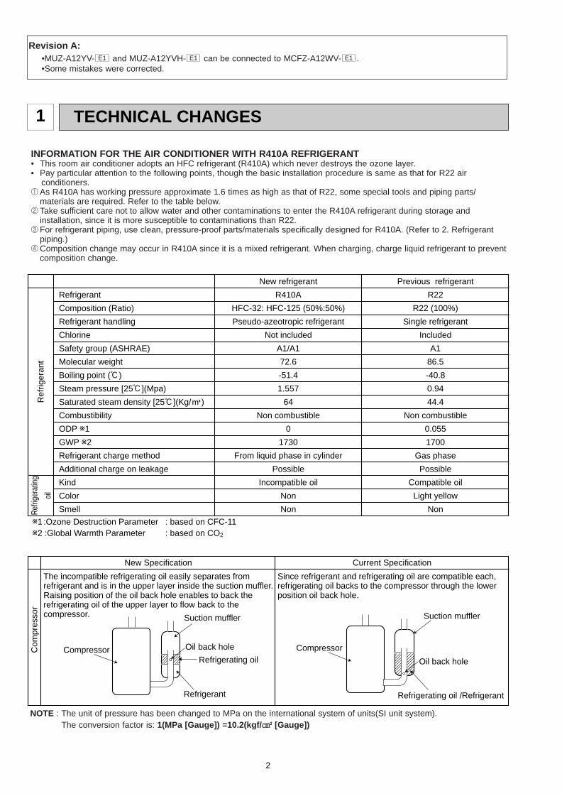
The incompatible refrigerating oil easily separates from refrigerant and is in the upper layer inside the suction muffler.Raising position of the oil back hole enables to back the refrigerating oil of the upper layer to flow back to the compressor.
Since refrigerant and refrigerating oil are compatible each, refrigerating oil backs to the compressor through the lower position oil back hole.
Compressor
Suction muffler
Oil back hole
Refrigerating oil
Refrigerant
Compressor
Suction muffler
Oil back hole
Refrigerating oil /Refrigerant
Com
pres
sor
Revision A:•MUZ-A12YV- and MUZ-A12YVH- can be connected to MCFZ-A12WV- .•Some mistakes were corrected.
E1E1E1
OB328 A--1qxp 04.4.26 4:49 PM Page 2
3
-30 -20 -10 0 10 20 30 40 50 60-0.5
0.0
0.5
1.0
1.5
2.0
2.5
3.0
3.5
4.0(MPa [Gauge])
R410A
R22
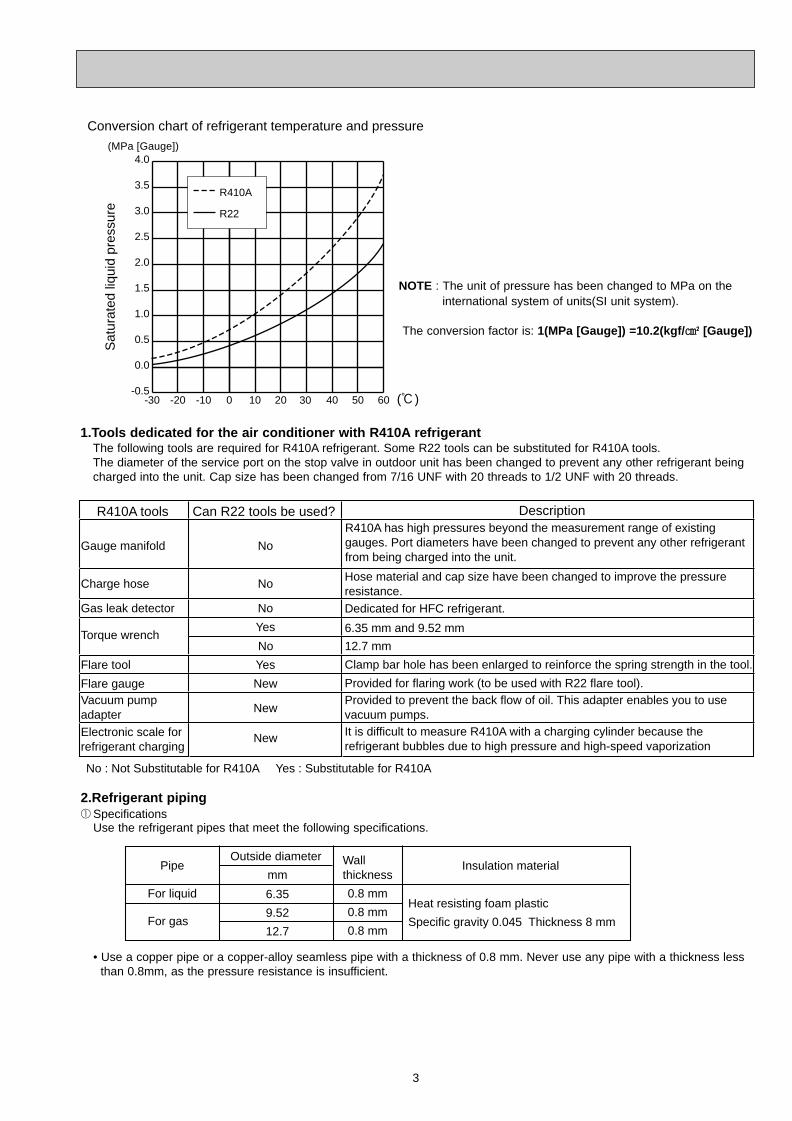
Conversion chart of refrigerant temperature and pressureS
atur
ated
liqu
id p
ress
ure
(:)
NOTE : The unit of pressure has been changed to MPa on the international system of units(SI unit system).
The conversion factor is: 1(MPa [Gauge]) =10.2(kgf/ ff [Gauge])
R410A tools Can R22 tools be used?
Gas leak detector
R410A has high pressures beyond the measurement range of existing gauges. Port diameters have been changed to prevent any other refrigerant from being charged into the unit.
Hose material and cap size have been changed to improve the pressure resistance.Dedicated for HFC refrigerant.
6.35 mm and 9.52 mm
Description
Clamp bar hole has been enlarged to reinforce the spring strength in the tool.
Provided for flaring work (to be used with R22 flare tool).Provided to prevent the back flow of oil. This adapter enables you to use vacuum pumps.It is difficult to measure R410A with a charging cylinder because the refrigerant bubbles due to high pressure and high-speed vaporization
No
No
No
Yes
Yes
New
New
New
Gauge manifold
Charge hose
Torque wrench
Flare tool
Flare gaugeVacuum pumpadapter
Electronic scale forrefrigerant charging
No : Not Substitutable for R410A Yes : Substitutable for R410A
No 12.7 mm
1.Tools dedicated for the air conditioner with R410A refrigerantThe following tools are required for R410A refrigerant. Some R22 tools can be substituted for R410A tools.The diameter of the service port on the stop valve in outdoor unit has been changed to prevent any other refrigerant being charged into the unit. Cap size has been changed from 7/16 UNF with 20 threads to 1/2 UNF with 20 threads.
2.Refrigerant piping1Specifications
Use the refrigerant pipes that meet the following specifications.
• Use a copper pipe or a copper-alloy seamless pipe with a thickness of 0.8 mm. Never use any pipe with a thickness less than 0.8mm, as the pressure resistance is insufficient.
Wallthickness
Outside diameterPipe
mm
For liquid
For gas
6.35
9.52
12.7
0.8 mm
0.8 mm
0.8 mm
Heat resisting foam plastic
Specific gravity 0.045 Thickness 8 mm
Insulation material
OB328 A--1qxp 04.4.26 4:49 PM Page 3
4
Electronic scale for refrigerant charging
Outdoor unit
Refrigerant gas cylinderoperating valve
Refrigerant gas cylinderfor R410A with siphon
Refrigerant (liquid)
Service port
Gauge manifold valve (for R410A)
Union
Liquid pipe
Gas pipe
Stop valve
Indoor unit
Charge hose (for R410A)
R410A
Pipe diameter
mm
6.35
9.52
12.7
17
22
26
Dimension of flare nut
R22
17
22
24
2Flaring work and flare nutFlaring work for R410A pipe differs from that for R22 pipe.For details of flaring work, refer to Installation manual “FLARING WORK”.
3.Refrigerant oilApply the special refrigeration oil (accessories: packed with indoor unit) to the flare and the union seat surfaces.
4.Air purge• Do not discharge the refrigerant into the atmosphere.
Take care not to discharge refrigerant into the atmosphere during installation, reinstallation, or repairs to the refrigerant circuit.
• Use the vacuum pump for air purging for the purpose of environmental protection.
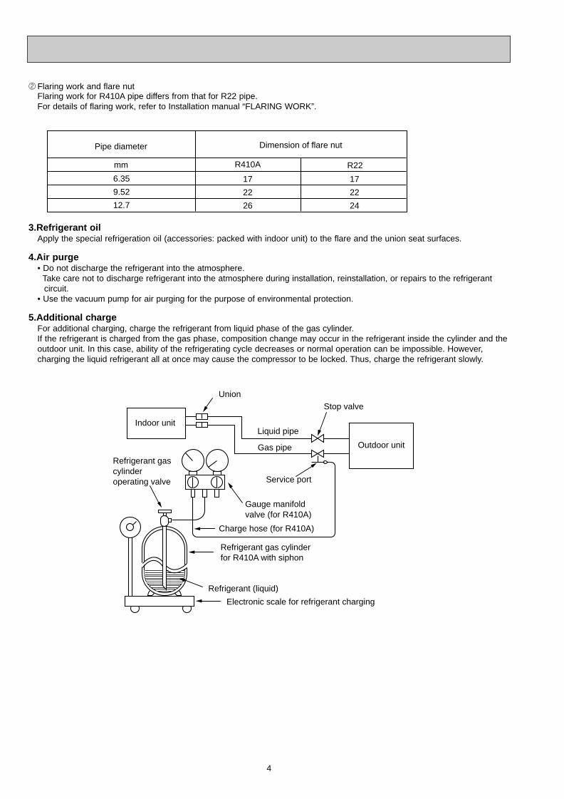
5.Additional chargeFor additional charging, charge the refrigerant from liquid phase of the gas cylinder. If the refrigerant is charged from the gas phase, composition change may occur in the refrigerant inside the cylinder and theoutdoor unit. In this case, ability of the refrigerating cycle decreases or normal operation can be impossible. However, charging the liquid refrigerant all at once may cause the compressor to be locked. Thus, charge the refrigerant slowly.
OB328 A--1qxp 04.4.26 4:49 PM Page 4
5
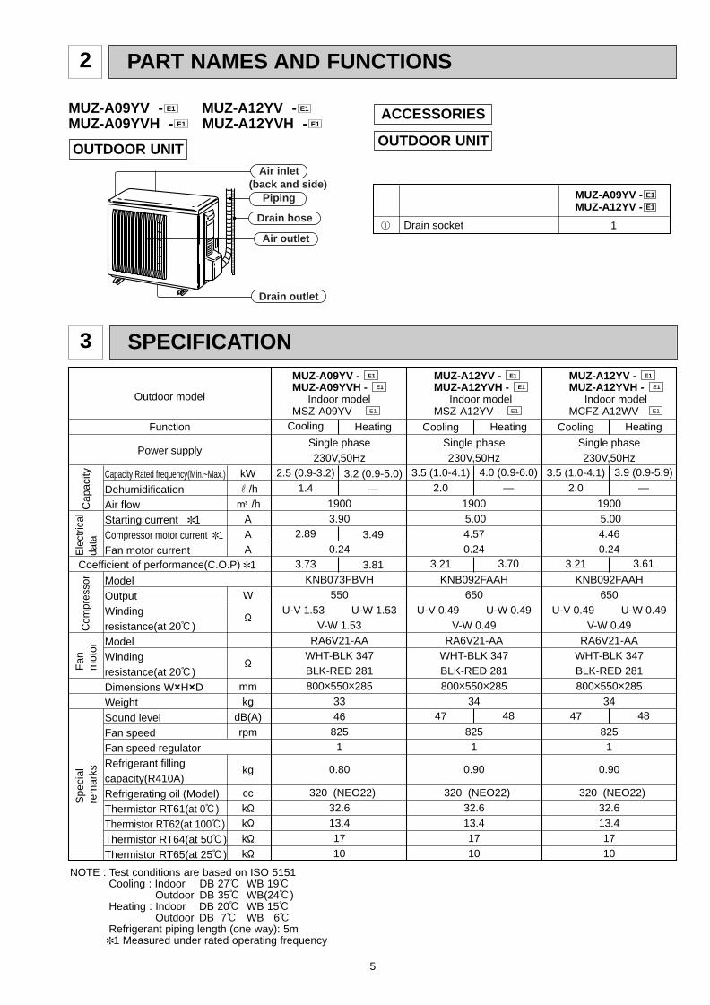
PART NAMES AND FUNCTIONS2
OUTDOOR UNITAir inlet
Air outlet
Drain outlet
Piping
Drain hose
(back and side)
ACCESSORIES
1 Drain socket 1
MUZ-A09YV - E1
MUZ-A12YV - E1
OUTDOOR UNIT
Single phase230V,50Hz
19003.90
0.24
KNB073FBVH550
U-V 1.53 U-W 1.53 V-W 1.53
RA6V21-AAWHT-BLK 347 BLK-RED 281800o550o285
3346
8251
0.80
320 (NEO22)32.613.41710
Cooling
2.5 (0.9-3.2)1.4
2.89
3.73
Heating
3.2 (0.9-5.0)—
3.49
3.81
MUZ-A09YV - E1
E1 MUZ-A09YVH -
E1 MSZ-A09YV -Indoor model
E1 MSZ-A12YV -Indoor model
Single phase230V,50Hz
1900 5.004.570.24
KNB092FAAH650
U-V 0.49 U-W 0.49 V-W 0.49
RA6V21-AAWHT-BLK 347 BLK-RED 281800o550o285
34
8251
0.90
320 (NEO22)32.613.41710
Cooling
3.5 (1.0-4.1)2.0
3.21
47
Heating
4.0 (0.9-6.0)—
3.70
48
Outdoor model
Function
Power supply
Capacity Rated frequency(Min.~Max.)DehumidificationAir flowStarting current ✽1Compressor motor current ✽1Fan motor current
ModelOutputWindingresistance(at 20:)ModelWindingresistance(at 20:)Dimensions WOHODWeightSound levelFan speedFan speed regulatorRefrigerant fillingcapacity(R410A)Refrigerating oil (Model)Thermistor RT61(at 0:)Thermistor RT62(at 100:)Thermistor RT64(at 50:)Thermistor RT65(at 25:)
kWr/hK /h
AAA
✽1
W
"
"
mmkg
dB(A)rpm
kg
cck"k"k"k"
Com
pres
sor
Fan
m
otor
Spe
cial
rem
arks
Coefficient of performance(C.O.P)
Cap
acity
Ele
ctric
alda
ta
MUZ-A12YV - E1
E1 MUZ-A12YVH -
E1 MCFZ-A12WV -Indoor model
Single phase230V,50Hz
1900 5.004.460.24
KNB092FAAH650
U-V 0.49 U-W 0.49 V-W 0.49
RA6V21-AAWHT-BLK 347 BLK-RED 281800o550o285
34
8251
0.90
320 (NEO22)32.613.41710
Cooling
3.5 (1.0-4.1)2.0
3.21
47
Heating
3.9 (0.9-5.9)—
3.61
48
MUZ-A12YV - E1
E1 MUZ-A12YVH -
NOTE : Test conditions are based on ISO 5151Cooling : Indoor DB 27: WB 19:
Outdoor DB 35: WB(24:)Heating : Indoor DB 20: WB 15:
Outdoor DB 7: WB 6:Refrigerant piping length (one way): 5m✽1 Measured under rated operating frequency
3 SPECIFICATION
MUZ-A09YV - MUZ-A12YV -MUZ-A09YVH - MUZ-A12YVH - E1E1
E1E1
OB328 A--1qxp 04.4.26 4:49 PM Page 5
6
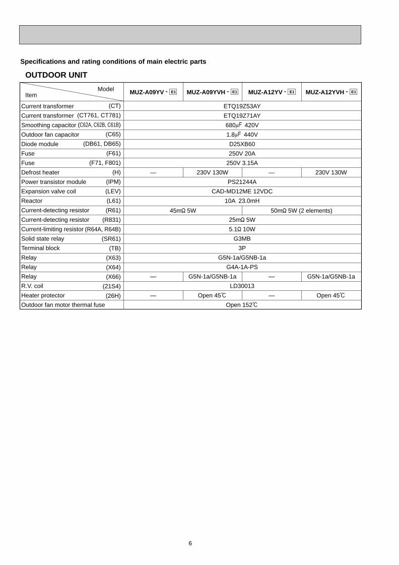
OUTDOOR UNIT
ModelItem
Current transformer
Current transformer
Smoothing capacitor
Outdoor fan capacitor
Diode module
Fuse
Fuse
Defrost heater
Power transistor module
Expansion valve coil
Reactor
Current-detecting resistor
Current-detecting resistor
Current-limiting resistor
Solid state relay
Terminal block
Relay
Relay
Relay
R.V. coil
Heater protector
Outdoor fan motor thermal fuse
MUZ-A09YV - E1
(CT)
(CT761, CT781)
(C62A, C62B, C61B)
(C65)
(DB61, DB65)
(F61)
(F71, F801)
(H)
(IPM)
(LEV)
(L61)
(R61)
(R831)
(R64A, R64B)
(SR61)
(TB)
(X63)
(X64)
(X66)
(21S4)
(26H)
MUZ-A09YVH - E1 MUZ-A12YV - E1 MUZ-A12YVH - E1
ETQ19Z53AY
ETQ19Z71AY
680+ 420V
1.8+ 440V
D25XB60
250V 20A
250V 3.15A
PS21244A
CAD-MD12ME 12VDC
10A 23.0mH
25m" 5W
5.1" 10W
G3MB
3P
G5N-1a/G5NB-1a
G4A-1A-PS
LD30013
Open 152:
—
—
—
230V 130W
G5N-1a/G5NB-1a
Open 45:
—
—
—
230V 130W
G5N-1a/G5NB-1a
Open 45:
45m" 5W 50m" 5W (2 elements)
Specifications and rating conditions of main electric parts
OB328 A--1qxp 04.4.26 4:49 PM Page 6
7
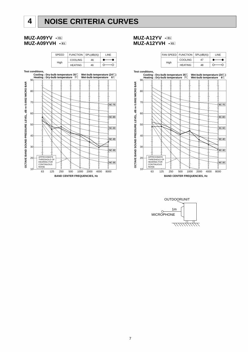
NOISE CRITERIA CURVES4
90
80
70
60
50
40
30
20
1063 125 250 500 1000 2000 4000 8000
NC-60
NC-50
NC-40
NC-30
NC-20
NC-70
OC
TAV
E B
AN
D S
OU
ND
PR
ES
SU
RE
LE
VE
L, d
B r
e 0.
0002
MIC
RO
BA
R
BAND CENTER FREQUENCIES, Hz
Test conditions, Cooling : Dry-bulb temperature 35: Wet-bulb temperature (24:)
APPROXIMATETHRESHOLD OF HEARING FORCONTINUOUSNOISE
COOLING
FUNCTION SPL(dB(A)) LINE
High
SPEED
HEATING
46
46
Heating : Dry-bulb temperature 7: Wet-bulb temperature 6:
MUZ-A09YV -MUZ-A09YVH - E1
E1
90
80
70
60
50
40
30
20
1063 125 250 500 1000 2000 4000 8000
NC-60
NC-50
NC-40
NC-30
NC-20
NC-70
OC
TAV
E B
AN
D S
OU
ND
PR
ES
SU
RE
LE
VE
L, d
B r
e 0.
0002
MIC
RO
BA
R
BAND CENTER FREQUENCIES, Hz
APPROXIMATETHRESHOLD OF HEARING FORCONTINUOUSNOISE
COOLING
FUNCTION SPL(dB(A)) LINE
High
FAN SPEED
HEATING
47
48
Test conditions, Cooling : Dry-bulb temperature 35: Wet-bulb temperature (24:) Heating : Dry-bulb temperature 7: Wet-bulb temperature 6:
OUTDOORUNIT
MICROPHONE
1m
MUZ-A12YV -MUZ-A12YVH - E1
E1
OB328 A--1qxp 04.4.26 4:49 PM Page 7
8
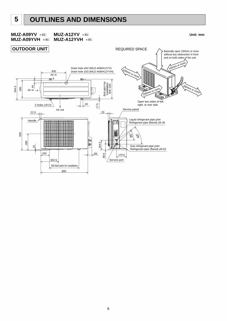
5 OUTLINES AND DIMENSIONS
10
69
800
302.5
500 Bolt pitch for installation
150
22.3
Handle
550
280
164.
5
99.5 170.5
23Service panel
Service port
285
344.
5 44
400Air in
Air out
Air in
17.5
Bol
t pitc
h fo
rin
stal
latio
n30
4~32
5
40
Liquid refrigerant pipe jointRefrigerant pipe (flared) [6.35
Gas refrigerant pipe jointRefrigerant pipe (flared) [9.52
43-
35-
2 holes 10o21
Drain hole [33 (MUZ-A09/A12YVH)Drain hole [42 (MUZ-A09/A12YV)
REQUIRED SPACEBasically open 100mm or more without any obstruction in front and on both sides of the unit.
350mm or more200mm or more
100mm or more
100mm or more
Open two sides of left, right, or rear side.
Unit: mm
OUTDOOR UNIT
MUZ-A09YV - MUZ-A12YV -MUZ-A09YVH - MUZ-A12YVH - E1E1
E1E1
OB328 A--1qxp 04.4.26 4:49 PM Page 8
9
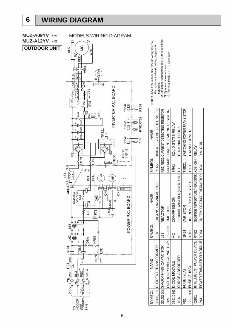
WIRING DIAGRAM6
OUTDOOR UNIT
WH
TR6
4AW
HT
BLU
BLU
RE
D
NT
OIN
DO
OR
UN
ITC
ON
NE
C-
TIN
G
230V
~
12V
2 3
GRN
/YLW
TB
R64B
R83
13
CN
771
CN
800
CN
642
42
1
INV
ER
TE
R P
.C. B
OA
RD
CN
641
21
3CN
601
3C
N64
32
11
2
7
PO
WE
R P
.C. B
OA
RD
RT
61R
T62
RT
64R
T65
GR
NF
71
CT
LDE
NR
61
TR
821
DB
65
6LE
VC N 7 2 4
IC80
1
SR
61C
65121
CN
721
X63
21S4
MF
2
1 2 3
BLK
TAB6
2
3
X64
L62
TAB6
1F
61
DS
A
L63
T80
1
BLK B
LU
C62
AC
62B
BLU
LD70
DB
61
LD69
4
TA
B63
BLK
L61
P
WVU
N
R61
2C
T76
1
CT
781
IPM
CN
61
UW
MC
WH
T
BLK
V
RE
DR
ED
BLK
WH
T1 3
LD-U
LD-W
LD-V
C61
BF
801
C N 7 2 6
C N 7 2 5
++
+
SY
MB
OL
CT,CT
761,C
T781
C62A
,C62B
,C61B
C65
DB61
,DB6
5
DS
A
F61
F71
,F80
1
IC80
1
IPM
SY
MB
OL
LEV
L61
L62,
L63
MC
MF
NR
61
RT
61
RT
62
RT
64
SY
MB
OL
RT
65
R61
,R83
1
R64A
,R64
B
SR
61
TB
TR
821
T80
1
X63
,X64
21S
4
N
AM
E
CU
RR
EN
T T
RA
NS
FO
RM
ER
SM
OO
TH
ING
CA
PA
CIT
OR
OU
TD
OO
R F
AN
CA
PA
CIT
OR
DIO
DE
MO
DU
LE
SU
RG
E A
BS
OR
BE
R
FU
SE
(20
A)
FU
SE
(3.
15A
)
INTE
LLIG
EN
T P
OW
ER
DE
VIC
E
PO
WE
R T
RA
NS
ISTO
R M
OD
ULE
N
AM
E
EX
PA
NS
ION
VA
LVE
CO
IL
RE
AC
TO
R
CM
C C
OIL
CO
MP
RE
SS
OR
OUT
DOO
R FA
N M
OTO
R (IN
NER
FUSE
)
VA
RIS
TO
R
DE
FR
OS
T T
HE
RM
IST
OR
DISC
HARG
E TE
MPER
ATUR
E TH
ERMI
STOR
FIN
TEM
PER
ATU
RE
THER
MIS
TOR
NA
ME
AMBI
ENT
TEM
PERA
TURE
THE
RMIS
TOR
CU
RR
ENT-
DET
ECTI
NG
RES
ISTO
R
CU
RR
EN
T-LI
MIT
ING
RE
SIS
TOR
SO
LID
STA
TE
RE
LAY
TE
RM
INA
L B
LOC
K
SWIT
CH
ING
PO
WER
TR
ANSI
STO
R
TR
AN
SF
OR
ME
R
RE
LAY
R.V
. CO
IL
NO
TE
:1. A
bout
the
indo
or s
ide
elec
tric
wiri
ng r
efer
to
the
indo
or u
nit
elec
tric
wiri
ng d
iagr
am f
or
serv
icin
g.2.
Use
cop
per
cond
ucto
rs o
nly.
(F
or f
ield
wiri
ng)
3. S
ymbo
ls b
elow
indi
cate
./
: Ter
min
al b
lock
,
: C
onne
ctor
MODELS WIRING DIAGRAMMUZ-A09YV -MUZ-A12YV - E1
E1
OB328 A--1qxp 04.4.26 4:49 PM Page 9
10
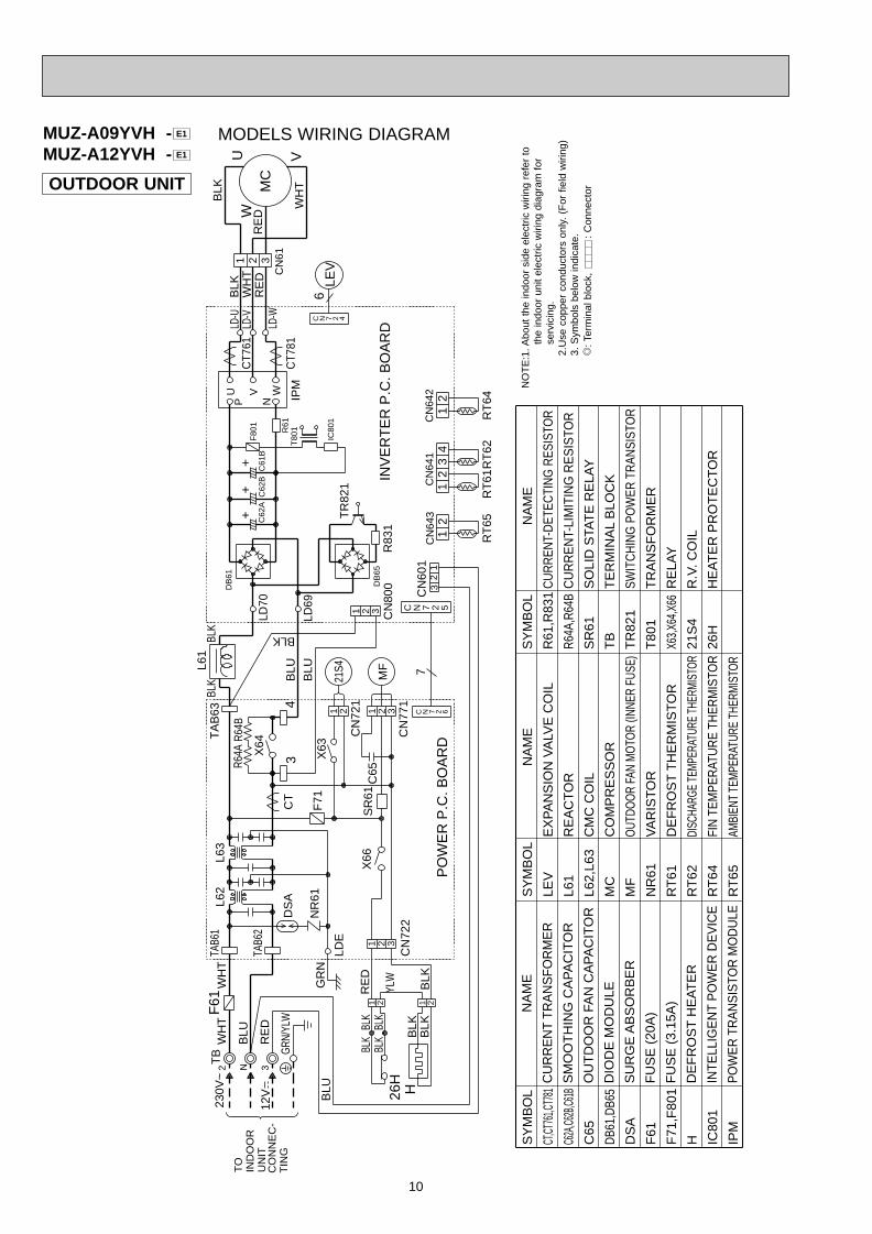
OUTDOOR UNIT
MUZ-A09YVH -MUZ-A12YVH - E1
E1
WH
TR6
4AW
HT
BLU
BLU
RE
D
N
230V
~
12V
2 3
GRN
/YLW
TB
R64B
26H
H
RE
D
BLK
21B
LKB
LK
BLK
BLK
BLK
BLK
YLW
21
BLU
BLU
BLK
GR
N
TAB6
2
F71CT
3
X64
L62
TAB6
1
LDE
F61
DS
A
NR
61
L63
T80
1
BLK
C62
AC
62B
TR
821
LD70
DB
61
DB
65
LD69
4
TA
B63
R83
1
BLK
L61
P
WVU
N
R61
6LE
V2C
T761
CT7
81IP
MC
N61
U
MC
W
WH
T
BLK
V
RE
DR
ED
BLK
WH
T1 3
LD-U
LD-W
LD-V
C61
BF
801
IC80
1
CN
722
321X
66S
R61
C65
121
CN
721
X63
21S4
MF
2 3C
N77
1C
N80
0
1 2 3
CN
642
42
1
INV
ER
TE
R P
.C. B
OA
RD
CN
641
21
3C
N60
1
3C
N64
32
1 RT
65R
T61
RT
62R
T64
12
7
SY
MB
OL
CT,CT
761,C
T781
C62A
,C62B
,C61B
C65
DB61
,DB6
5
DS
A
F61
F71
,F80
1
H IC80
1
IPM
SY
MB
OL
LEV
L61
L62,
L63
MC
MF
NR
61
RT
61
RT
62
RT
64
RT
65
SY
MB
OL
R61
,R83
1
R64A
,R64
B
SR
61
TB
TR
821
T80
1
X63,
X64,
X66
21S
4
26H
N
AM
E
CU
RR
EN
T T
RA
NS
FO
RM
ER
SM
OO
TH
ING
CA
PA
CIT
OR
OU
TD
OO
R F
AN
CA
PA
CIT
OR
DIO
DE
MO
DU
LE
SU
RG
E A
BS
OR
BE
R
FU
SE
(20
A)
FU
SE
(3.
15A
)
DE
FR
OS
T H
EA
TE
R
INTE
LLIG
EN
T P
OW
ER
DE
VIC
E
PO
WE
R T
RA
NS
ISTO
R M
OD
ULE
N
AM
E
EX
PA
NS
ION
VA
LVE
CO
IL
RE
AC
TO
R
CM
C C
OIL
CO
MP
RE
SS
OR
OUT
DOO
R FA
N M
OTO
R (IN
NER
FUSE
)
VA
RIS
TO
R
DE
FR
OS
T T
HE
RM
IST
OR
DISC
HARG
E TE
MPER
ATUR
E TH
ERMI
STOR
FIN
TEM
PER
ATU
RE
THER
MIS
TOR
AMBI
ENT
TEM
PERA
TURE
THE
RMIS
TOR
NA
ME
CU
RR
ENT-
DET
ECTI
NG
RES
ISTO
R
CU
RR
EN
T-LI
MIT
ING
RE
SIS
TOR
SO
LID
STA
TE
RE
LAY
TE
RM
INA
L B
LOC
K
SWIT
CH
ING
PO
WER
TR
ANSI
STO
R
TR
AN
SF
OR
ME
R
RE
LAY
R.V
. CO
IL
HE
AT
ER
PR
OT
EC
TO
R
PO
WE
R P
.C. B
OA
RD
C N 7 2 4
++
+
C N 7 2 5
C N 7 2 6
TO
IND
OO
RU
NIT
CO
NN
EC
-T
ING
NO
TE
:1. A
bout
the
indo
or s
ide
elec
tric
wiri
ng r
efer
to
the
indo
or u
nit
elec
tric
wiri
ng d
iagr
am f
or
serv
icin
g.2.
Use
cop
per
cond
ucto
rs o
nly.
(F
or f
ield
wiri
ng)
3. S
ymbo
ls b
elow
indi
cate
./
: Ter
min
al b
lock
,
: C
onne
ctor
MODELS WIRING DIAGRAM
OB328 A--1qxp 04.4.26 4:49 PM Page 10
11
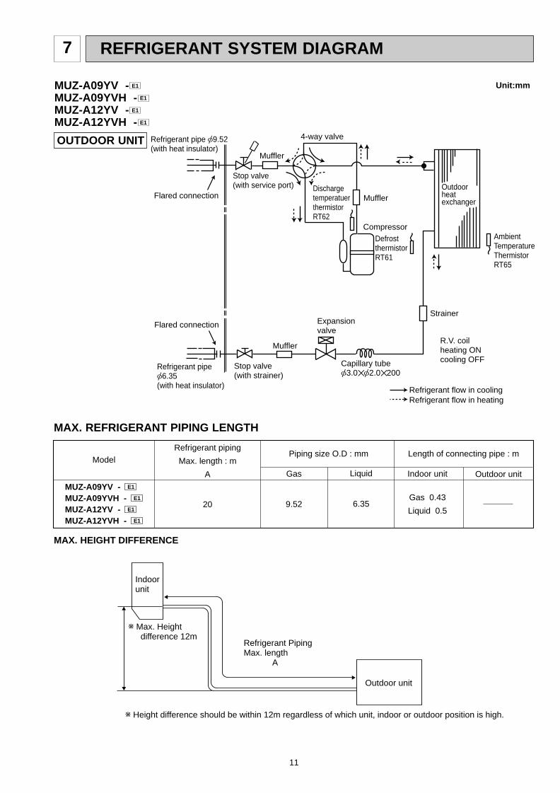
REFRIGERANT SYSTEM DIAGRAM7
OUTDOOR UNIT
Unit:mm
Outdoorheatexchanger
Flared connection
DefrostthermistorRT61
AmbientTemperatureThermistorRT65
DischargetemperatuerthermistorRT62
Flared connection
Stop valve(with strainer)
Stop valve(with service port)
Refrigerant flow in cooling
Compressor
Muffler
4-way valve
Refrigerant flow in heating
Refrigerant pipe [9.52(with heat insulator)
Refrigerant pipe [6.35(with heat insulator)
R.V. coilheating ONcooling OFF
Strainer
Capillary tube[3.0✕[2.0✕200
Expansionvalve
Muffler
Muffler
MUZ-A09YV -MUZ-A09YVH -MUZ-A12YV -MUZ-A12YVH - E1
E1
E1
E1
Refrigerant PipingMax. length A
w Height difference should be within 12m regardless of which unit, indoor or outdoor position is high.
w Max. Heightdifference 12m
Indoorunit
Outdoor unit
MAX. HEIGHT DIFFERENCE
MAX. REFRIGERANT PIPING LENGTH
Refrigerant piping
Max. length : m
A
20
Indoor unit
Gas 0.43
Liquid 0.5
Gas
9.52
Liquid
6.35
Outdoor unit
Piping size O.D : mm Length of connecting pipe : mModel
MUZ-A09YV - E1
MUZ-A09YVH - E1
MUZ-A12YV - E1
MUZ-A12YVH - E1
OB328 A--1qxp 04.4.26 4:49 PM Page 11
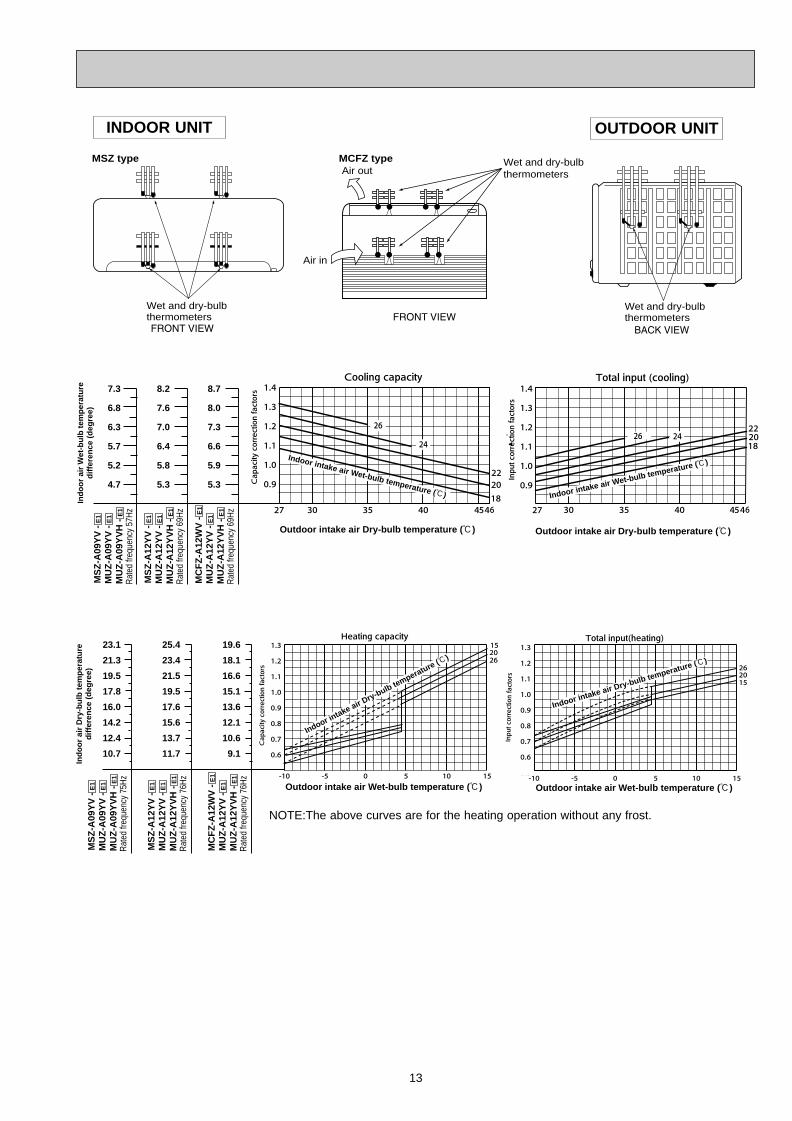
PERFORMANCE CURVES8
12
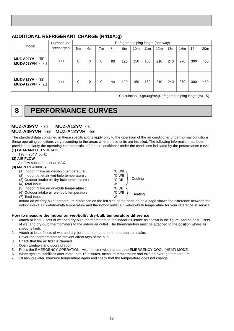
The standard data contained in these specifications apply only to the operation of the air conditioner under normal conditions.Since operating conditions vary according to the areas where these units are installed. The following information has beenprovided to clarify the operating characteristics of the air conditioner under the conditions indicated by the performance curve.(1) GUARANTEED VOLTAGE
198 ~ 264V, 50Hz(2) AIR FLOW
Air flow should be set at MAX.(3) MAIN READINGS
(1) Indoor intake air wet-bulb temperature : °C WB(2) Indoor outlet air wet-bulb temperature : °C WB(3) Outdoor intake air dry-bulb temperature : °C DB(4) Total input: W(5) Indoor intake air dry-bulb temperature : °C DB(6) Outdoor intake air wet-bulb temperature : °C WB(7) Total input : WIndoor air wet/dry-bulb temperature difference on the left side of the chart on next page shows the difference between theindoor intake air wet/dry-bulb temperature and the indoor outlet air wet/dry-bulb temperature for your reference at service.
}}
Cooling
Heating
How to measure the indoor air wet-bulb / dry-bulb temperature difference1. Attach at least 2 sets of wet and dry-bulb thermometers to the indoor air intake as shown in the figure, and at least 2 sets
of wet and dry-bulb thermometers to the indoor air outlet. The thermometers must be attached to the position where airspeed is high.
2. Attach at least 2 sets of wet and dry-bulb thermometers to the outdoor air intake.Cover the thermometers to prevent direct rays of the sun.
3. Check that the air filter is cleaned.4. Open windows and doors of room.5. Press the EMERGENCY OPERATION switch once (twice) to start the EMERGENCY COOL (HEAT) MODE.6. When system stabilizes after more than 15 minutes, measure temperature and take an average temperature.7. 10 minutes later, measure temperature again and check that the temperature does not change.
MUZ-A09YV - MUZ-A12YV -MUZ-A09YVH - MUZ-A12YVH - E1E1
E1E1
ADDITIONAL REFRIGERANT CHARGE (R410A:g)Outdoor unit precharged
800
900
14m
270
270
7m
0
0
6m
0
0
5m
0
0
11m
180
180
Model Refrigerant piping length (one way)
Calculation : Xg=30g/mo(Refrigerant piping length(m) - 5)
8m
90
90
9m
120
120
10m
150
150
12m
210
210
13m
240
240
15m
300
300
20m
450
450
MUZ-A09YV - E1
MUZ-A09YVH - E1
MUZ-A12YV - E1 MUZ-A12YVH - E1
OB328 A--1qxp 04.4.26 4:49 PM Page 12
13
INDOOR UNIT OUTDOOR UNIT
Wet and dry-bulbthermometers
Wet and dry-bulbthermometers
MSZ type MCFZ type
Air in
Air outWet and dry-bulbthermometers
Ind
oo
r ai
r W
et-b
ulb
tem
per
atu
red
iffe
ren
ce (
deg
ree)
Indoor intake air Wet-bulb temperature (:)
Outdoor intake air Dry-bulb temperature (:)
Indoor intake air Wet-bulb temperature (:)
Outdoor intake air Dry-bulb temperature (:)
MS
Z-A
09Y
V -
E1
MU
Z-A
09Y
V -
E1
MU
Z-A
09Y
VH
- E
1
7.3
6.8
6.3
5.7
5.2
4.7
8.2
7.6
7.0
6.4
5.8
5.3
Rat
ed fr
eque
ncy
57H
z
MS
Z-A
12Y
V -
E1
MU
Z-A
12Y
V -
E1
MU
Z-A
12Y
VH
- E
1R
ated
freq
uenc
y 69
Hz
8.7
8.0
7.3
6.6
5.9
5.3
MC
FZ
-A12
WV
- E
1
MU
Z-A
12Y
V -
E1
MU
Z-A
12Y
VH
- E
1R
ated
freq
uenc
y 69
Hz
23.1
21.3
19.5
17.8
16.0
14.2
12.4
10.7
25.4
23.4
21.5
19.5
17.6
15.6
13.7
11.7
Ind
oo
r ai
r D
ry-b
ulb
tem
per
atu
red
iffe
ren
ce (
deg
ree)
Indoor intake air D
ry-bulb temperature (:)
Outdoor intake air Wet-bulb temperature (:) Outdoor intake air Wet-bulb temperature (:)
Indoor intake air Dry-bulb temperature (:)
MS
Z-A
09Y
V -
E1
MU
Z-A
09Y
V -
E1
MU
Z-A
09Y
VH
- E
1R
ated
freq
uenc
y 75
Hz
MS
Z-A
12Y
V -
E1
MU
Z-A
12Y
V -
E1
MU
Z-A
12Y
VH
- E
1R
ated
freq
uenc
y 76
Hz
19.6
18.1
16.6
15.1
13.6
12.1
10.6
9.1
MC
FZ
-A12
WV
- E
1
MU
Z-A
12Y
V -
E1
MU
Z-A
12Y
VH
- E
1R
ated
freq
uenc
y 76
Hz
NOTE:The above curves are for the heating operation without any frost.
OB328 A--1qxp 04.4.26 4:49 PM Page 13
14
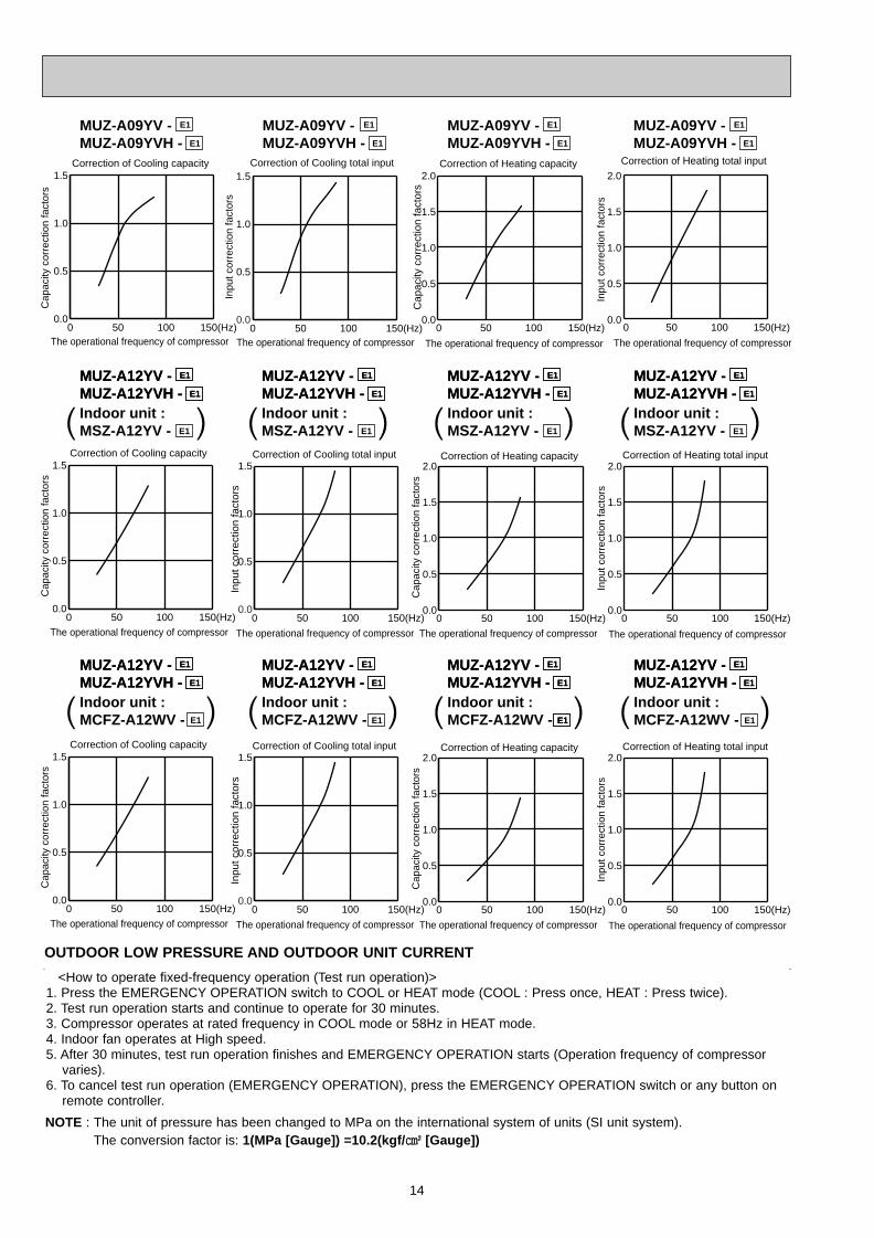
<How to operate fixed-frequency operation (Test run operation)> 1. Press the EMERGENCY OPERATION switch to COOL or HEAT mode (COOL : Press once, HEAT : Press twice).2. Test run operation starts and continue to operate for 30 minutes.3. Compressor operates at rated frequency in COOL mode or 58Hz in HEAT mode.4. Indoor fan operates at High speed.5. After 30 minutes, test run operation finishes and EMERGENCY OPERATION starts (Operation frequency of compressor
varies).6. To cancel test run operation (EMERGENCY OPERATION), press the EMERGENCY OPERATION switch or any button on
remote controller.
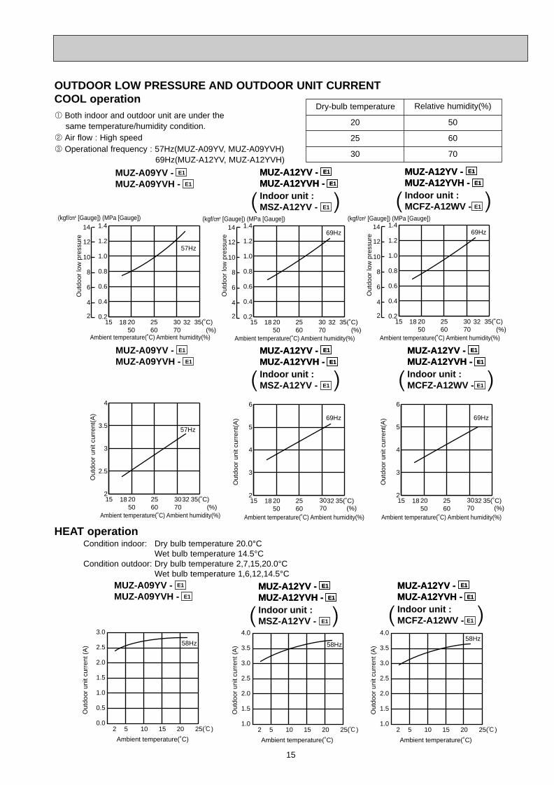
OUTDOOR LOW PRESSURE AND OUTDOOR UNIT CURRENT
NOTE : The unit of pressure has been changed to MPa on the international system of units (SI unit system).The conversion factor is: 1(MPa [Gauge]) =10.2(kgf/ ff [Gauge])
Correction of Cooling total input
Inpu
t cor
rect
ion
fact
ors
The operational frequency of compressor0 50 100 150(Hz)
0.0
0.5
1.0
1.5
0 50 100 150(Hz)0.0
0.5
1.0
1.5Correction of Cooling capacity
Cap
acity
cor
rect
ion
fact
ors
The operational frequency of compressor
0 50 100 150(Hz)0.0
0.5
1.0
1.5Correction of Cooling capacity
Cap
acity
cor
rect
ion
fact
ors
The operational frequency of compressor
Correction of Cooling total input
Inpu
t cor
rect
ion
fact
ors
The operational frequency of compressor
0 50 100 150(Hz)0.0
0.5
1.0
1.5
Correction of Heating total input
The operational frequency of compressor
0 50 100 150(Hz)
2.0
1.5
1.0
0.5
0.0
2.0
1.5
1.0
0.5
0.0
2.0
1.5
1.0
0.5
0.0
2.0
1.5
1.0
0.5
0.00 50 100 150(Hz)
Correction of Heating capacity
Cap
acity
cor
rect
ion
fact
ors
The operational frequency of compressor
Correction of Heating total input
Inpu
t cor
rect
ion
fact
ors
The operational frequency of compressor
0 50 100 150(Hz)0 50 100 150(Hz)
Correction of Heating capacity
Cap
acity
cor
rect
ion
fact
ors
The operational frequency of compressor
Inpu
t cor
rect
ion
fact
ors
MUZ-A09YV -MUZ-A09YVH -
E1
E1
MUZ-A09YV -MUZ-A09YVH -
E1
E1
MUZ-A09YV -MUZ-A09YVH -
E1
E1
MUZ-A09YV -MUZ-A09YVH -
E1
E1
0 50 100 150(Hz)0.0
0.5
1.0
1.5Correction of Cooling capacity
Cap
acity
cor
rect
ion
fact
ors
The operational frequency of compressor
Correction of Cooling total input
Inpu
t cor
rect
ion
fact
ors
The operational frequency of compressor
0 50 100 150(Hz)0.0
0.5
1.0
1.5 2.0
1.5
1.0
0.5
0.0
2.0
1.5
1.0
0.5
0.0
Correction of Heating total input
Inpu
t cor
rect
ion
fact
ors
The operational frequency of compressor
0 50 100 150(Hz)0 50 100 150(Hz)
Correction of Heating capacity
Cap
acity
cor
rect
ion
fact
ors
The operational frequency of compressor
MUZ-A12YV -MUZ-A12YVH -
E1
E1
Indoor unit :MSZ-A12YV - E1
MUZ-A12YV -MUZ-A12YVH -
E1
E1
( )MUZ-A12YV -MUZ-A12YVH -
E1
E1
Indoor unit :MSZ-A12YV - E1
MUZ-A12YV -MUZ-A12YVH -
E1
E1
( )MUZ-A12YV -MUZ-A12YVH -
E1
E1
Indoor unit :MSZ-A12YV - E1
MUZ-A12YV -MUZ-A12YVH -
E1
E1
( )MUZ-A12YV -MUZ-A12YVH -
E1
E1
Indoor unit :MSZ-A12YV - E1
MUZ-A12YV -MUZ-A12YVH -
E1
E1
( )
MUZ-A12YV -MUZ-A12YVH -
E1
E1
Indoor unit :MCFZ-A12WV - E1
MUZ-A12YV -MUZ-A12YVH -
E1
E1
( )MUZ-A12YV -MUZ-A12YVH -
E1
E1
Indoor unit :MCFZ-A12WV -
MUZ-A12YV -MUZ-A12YVH -
E1
E1
E1( )MUZ-A12YV -MUZ-A12YVH -
E1
E1
Indoor unit :MCFZ-A12WV -
MUZ-A12YV -MUZ-A12YVH -
E1
E1
E1E1( )MUZ-A12YV -MUZ-A12YVH -
E1
E1
Indoor unit :MCFZ-A12WV -
MUZ-A12YV -MUZ-A12YVH -
E1
E1
E1( )
OB328 A--1qxp 04.4.26 4:49 PM Page 14
15
2 Air flow : High speed3 Operational frequency : 57Hz(MUZ-A09YV, MUZ-A09YVH)
69Hz(MUZ-A12YV, MUZ-A12YVH)
(kgf/F [Gauge]) (MPa [Gauge])
18 3215 2050
2560
3070 (%)
35(˚C)0.2
0.4
0.6
0.8
1.0
1.257Hz
2
4
6
8
10
12
14 1.4
Ambient temperature(˚C) Ambient humidity(%)
Out
door
low
pre
ssur
e
MUZ-A09YV -MUZ-A09YVH -
E1
E1
15 2050
2560
3070 (%)
35(˚C)2
2.5
3
3.5
4
57Hz
3218
Out
door
uni
t cur
rent
(A)
Ambient temperature(˚C) Ambient humidity(%)
(kgf/F [Gauge]) (MPa [Gauge])
Ambient temperature(˚C) Ambient humidity(%)
Ambient temperature(˚C) Ambient humidity(%)
(kgf/F [Gauge]) (MPa [Gauge])
Ambient temperature(˚C) Ambient humidity(%)
Ambient temperature(˚C) Ambient humidity(%)
18 3215 2050
2560
3070 (%)
35(˚C)0.2
0.4
0.6
0.8
1.0
1.269Hz
1.4
15 2050
2560
3070 (%)
35(˚C)2
3
4
5
6
69Hz
3218
Out
door
low
pre
ssur
e
Out
door
uni
t cur
rent
(A)
MUZ-A09YV -MUZ-A09YVH -
E1
E1
2
4
6
8
10
12
14
MUZ-A12YV -MUZ-A12YVH -
E1
E1
Indoor unit :MSZ-A12YV - E1
MUZ-A12YV -MUZ-A12YVH -
E1
E1
( )
MUZ-A12YV -MUZ-A12YVH -
E1
E1
Indoor unit :MSZ-A12YV - E1
MUZ-A12YV -MUZ-A12YVH -
E1
E1
( )
18 3215 2050
2560
3070 (%)
35(˚C)0.2
0.4
0.6
0.8
1.0
1.269Hz
1.4
15 2050
2560
3070 (%)
35(˚C)2
3
4
5
6
69Hz
3218
Out
door
low
pre
ssur
e
Out
door
uni
t cur
rent
(A)
2
4
6
8
10
12
14
MUZ-A12YV -MUZ-A12YVH -
E1
E1
Indoor unit :MCFZ-A12WV - E1
MUZ-A12YV -MUZ-A12YVH -
E1
E1
( )
MUZ-A12YV -MUZ-A12YVH -
E1
E1
Indoor unit :MCFZ-A12WV - E1
MUZ-A12YV -MUZ-A12YVH -
E1
E1
( )
OUTDOOR LOW PRESSURE AND OUTDOOR UNIT CURRENTCOOL operation1 Both indoor and outdoor unit are under the
same temperature/humidity condition.
Dry-bulb temperature Relative humidity(%)
20 50
25 60
30 70
HEAT operationCondition indoor: Dry bulb temperature 20.0°C
Wet bulb temperature 14.5°CCondition outdoor: Dry bulb temperature 2,7,15,20.0°C
Wet bulb temperature 1,6,12,14.5°C
Out
door
uni
t cur
rent
(A
)
Out
door
uni
t cur
rent
(A
)
Ambient temperature(˚C) Ambient temperature(˚C)
MUZ-A09YV -MUZ-A09YVH -
E1
E1
Out
door
uni
t cur
rent
(A
)
Ambient temperature(˚C)
MUZ-A12YV -MUZ-A12YVH -
E1
E1
Indoor unit :MSZ-A12YV - E1
MUZ-A12YV -MUZ-A12YVH -
E1
E1
( )
MUZ-A12YV -MUZ-A12YVH -
E1
E1
Indoor unit :MCFZ-A12WV - E1
MUZ-A12YV -MUZ-A12YVH -
E1
E1
( )3.0
2.5
2.0
1.5
1.0
0.5
0.02 5 10 15 20 25(:)
58Hz
4.0
3.5
3.0
2.5
2.0
1.5
1.02 5 10 15 20 25(:)
58Hz
4.0
3.5
3.0
2.5
2.0
1.5
1.02 5 10 15 20 25(:)
58Hz
OB328 A--1qxp 04.4.26 4:49 PM Page 15
16
MSZ-A09YV - : MUZ-A09YV - MUZ-A09YVH - E1E1E1
21 1821 2022 1822 2022 2223 1823 2023 2224 1824 2024 2224 24
25 2025 2225 2426 1826 2026 2226 2426 2627 1827 2027 2227 2427 2628 1828 2028 2228 2428 2629 1829 2029 2229 2429 2630 1830 2030 2230 2430 2631 1831 2031 2231 2431 2632 1832 2032 2232 2432 26
INDOOR INDOOR
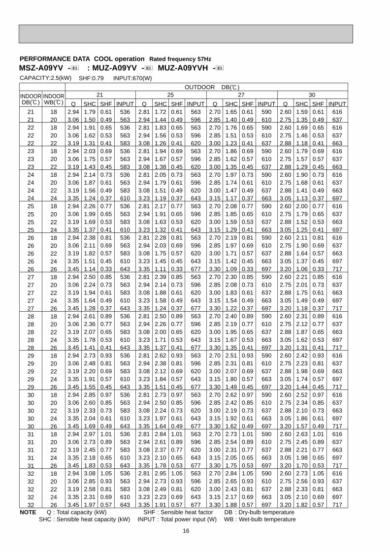
CAPACITY:2.5(kW) INPUT:670(W)SHF:0.79
21OUTDOOR DB(:)
25 27 30DB(:) WB(:) Q SHC SHF Q SHC SHF Q SHC SHF Q SHC SHFINPUT INPUT INPUT INPUT
2.94 1.79 0.61 536 2.81 1.72 0.61 563 2.70 1.65 0.61 590 2.60 1.59 0.61 6163.06 1.50 0.49 563 2.94 1.44 0.49 596 2.85 1.40 0.49 610 2.75 1.35 0.49 6372.94 1.91 0.65 536 2.81 1.83 0.65 563 2.70 1.76 0.65 590 2.60 1.69 0.65 6163.06 1.62 0.53 563 2.94 1.56 0.53 596 2.85 1.51 0.53 610 2.75 1.46 0.53 6373.19 1.31 0.41 583 3.08 1.26 0.41 620 3.00 1.23 0.41 637 2.88 1.18 0.41 6632.94 2.03 0.69 536 2.81 1.94 0.69 563 2.70 1.86 0.69 590 2.60 1.79 0.69 6163.06 1.75 0.57 563 2.94 1.67 0.57 596 2.85 1.62 0.57 610 2.75 1.57 0.57 6373.19 1.43 0.45 583 3.08 1.38 0.45 620 3.00 1.35 0.45 637 2.88 1.29 0.45 6632.94 2.14 0.73 536 2.81 2.05 0.73 563 2.70 1.97 0.73 590 2.60 1.90 0.73 6163.06 1.87 0.61 563 2.94 1.79 0.61 596 2.85 1.74 0.61 610 2.75 1.68 0.61 6373.19 1.56 0.49 583 3.08 1.51 0.49 620 3.00 1.47 0.49 637 2.88 1.41 0.49 6633.35 1.24 0.37 610 3.23 1.19 0.37 643 3.15 1.17 0.37 663 3.05 1.13 0.37 697
25 18 2.94 2.26 0.77 536 2.81 2.17 0.77 563 2.70 2.08 0.77 590 2.60 2.00 0.77 6163.06 1.99 0.65 563 2.94 1.91 0.65 596 2.85 1.85 0.65 610 2.75 1.79 0.65 6373.19 1.69 0.53 583 3.08 1.63 0.53 620 3.00 1.59 0.53 637 2.88 1.52 0.53 6633.35 1.37 0.41 610 3.23 1.32 0.41 643 3.15 1.29 0.41 663 3.05 1.25 0.41 6972.94 2.38 0.81 536 2.81 2.28 0.81 563 2.70 2.19 0.81 590 2.60 2.11 0.81 6163.06 2.11 0.69 563 2.94 2.03 0.69 596 2.85 1.97 0.69 610 2.75 1.90 0.69 6373.19 1.82 0.57 583 3.08 1.75 0.57 620 3.00 1.71 0.57 637 2.88 1.64 0.57 6633.35 1.51 0.45 610 3.23 1.45 0.45 643 3.15 1.42 0.45 663 3.05 1.37 0.45 6973.45 1.14 0.33 643 3.35 1.11 0.33 677 3.30 1.09 0.33 697 3.20 1.06 0.33 7172.94 2.50 0.85 536 2.81 2.39 0.85 563 2.70 2.30 0.85 590 2.60 2.21 0.85 6163.06 2.24 0.73 563 2.94 2.14 0.73 596 2.85 2.08 0.73 610 2.75 2.01 0.73 6373.19 1.94 0.61 583 3.08 1.88 0.61 620 3.00 1.83 0.61 637 2.88 1.75 0.61 6633.35 1.64 0.49 610 3.23 1.58 0.49 643 3.15 1.54 0.49 663 3.05 1.49 0.49 6973.45 1.28 0.37 643 3.35 1.24 0.37 677 3.30 1.22 0.37 697 3.20 1.18 0.37 7172.94 2.61 0.89 536 2.81 2.50 0.89 563 2.70 2.40 0.89 590 2.60 2.31 0.89 6163.06 2.36 0.77 563 2.94 2.26 0.77 596 2.85 2.19 0.77 610 2.75 2.12 0.77 6373.19 2.07 0.65 583 3.08 2.00 0.65 620 3.00 1.95 0.65 637 2.88 1.87 0.65 6633.35 1.78 0.53 610 3.23 1.71 0.53 643 3.15 1.67 0.53 663 3.05 1.62 0.53 6973.45 1.41 0.41 643 3.35 1.37 0.41 677 3.30 1.35 0.41 697 3.20 1.31 0.41 7172.94 2.73 0.93 536 2.81 2.62 0.93 563 2.70 2.51 0.93 590 2.60 2.42 0.93 6163.06 2.48 0.81 563 2.94 2.38 0.81 596 2.85 2.31 0.81 610 2.75 2.23 0.81 6373.19 2.20 0.69 583 3.08 2.12 0.69 620 3.00 2.07 0.69 637 2.88 1.98 0.69 6633.35 1.91 0.57 610 3.23 1.84 0.57 643 3.15 1.80 0.57 663 3.05 1.74 0.57 6973.45 1.55 0.45 643 3.35 1.51 0.45 677 3.30 1.49 0.45 697 3.20 1.44 0.45 7172.94 2.85 0.97 536 2.81 2.73 0.97 563 2.70 2.62 0.97 590 2.60 2.52 0.97 6163.06 2.60 0.85 563 2.94 2.50 0.85 596 2.85 2.42 0.85 610 2.75 2.34 0.85 6373.19 2.33 0.73 583 3.08 2.24 0.73 620 3.00 2.19 0.73 637 2.88 2.10 0.73 6633.35 2.04 0.61 610 3.23 1.97 0.61 643 3.15 1.92 0.61 663 3.05 1.86 0.61 6973.45 1.69 0.49 643 3.35 1.64 0.49 677 3.30 1.62 0.49 697 3.20 1.57 0.49 7172.94 2.97 1.01 536 2.81 2.84 1.01 563 2.70 2.73 1.01 590 2.60 2.63 1.01 6163.06 2.73 0.89 563 2.94 2.61 0.89 596 2.85 2.54 0.89 610 2.75 2.45 0.89 6373.19 2.45 0.77 583 3.08 2.37 0.77 620 3.00 2.31 0.77 637 2.88 2.21 0.77 6633.35 2.18 0.65 610 3.23 2.10 0.65 643 3.15 2.05 0.65 663 3.05 1.98 0.65 6973.45 1.83 0.53 643 3.35 1.78 0.53 677 3.30 1.75 0.53 697 3.20 1.70 0.53 7172.94 3.08 1.05 536 2.81 2.95 1.05 563 2.70 2.84 1.05 590 2.60 2.73 1.05 6163.06 2.85 0.93 563 2.94 2.73 0.93 596 2.85 2.65 0.93 610 2.75 2.56 0.93 6373.19 2.58 0.81 583 3.08 2.49 0.81 620 3.00 2.43 0.81 637 2.88 2.33 0.81 6633.35 2.31 0.69 610 3.23 2.23 0.69 643 3.15 2.17 0.69 663 3.05 2.10 0.69 6973.45 1.97 0.57 643 3.35 1.91 0.57 677 3.30 1.88 0.57 697 3.20 1.82 0.57 717
PERFORMANCE DATA COOL operation Rated frequency 57Hz
NOTE Q : Total capacity (kW) SHF : Sensible heat factor DB : Dry-bulb temperatureSHC : Sensible heat capacity (kW) INPUT : Total power input (W) WB : Wet-bulb temperature
OB328 A--1qxp 04.4.26 4:49 PM Page 16
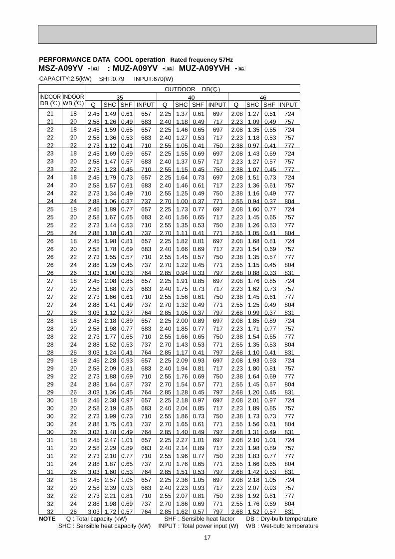
17
35 40 46
21 18
CAPACITY:2.5(kW) INPUT:670(W)SHF:0.79
OUTDOOR DB(:)
21 2022 1822 2022 2223 1823 2023 2224 1824 2024 2224 24
2525
2018
25 2225 2426 1826 2026 2226 2426 2627 1827 2027 2227 2427 2628 1828 2028 2228 2428 2629 1829 2029 2229 2429 2630 1830 2030 2230 2430 2631 1831 2031 2231 2431 2632 1832 2032 2232 2432 26
INDOOR INDOORDB (:) WB (:) Q SHC SHF INPUT Q SHC SHF INPUT Q SHC SHF INPUT
2.45 1.49 0.61 657 2.25 1.37 0.61 697 2.08 1.27 0.61 7242.58 1.26 0.49 683 2.40 1.18 0.49 717 2.23 1.09 0.49 7572.45 1.59 0.65 657 2.25 1.46 0.65 697 2.08 1.35 0.65 7242.58 1.36 0.53 683 2.40 1.27 0.53 717 2.23 1.18 0.53 7572.73 1.12 0.41 710 2.55 1.05 0.41 750 2.38 0.97 0.41 7772.45 1.69 0.69 657 2.25 1.55 0.69 697 2.08 1.43 0.69 7242.58 1.47 0.57 683 2.40 1.37 0.57 717 2.23 1.27 0.57 7572.73 1.23 0.45 710 2.55 1.15 0.45 750 2.38 1.07 0.45 7772.45 1.79 0.73 657 2.25 1.64 0.73 697 2.08 1.51 0.73 7242.58 1.57 0.61 683 2.40 1.46 0.61 717 2.23 1.36 0.61 7572.73 1.34 0.49 710 2.55 1.25 0.49 750 2.38 1.16 0.49 7772.88 1.06 0.37 737 2.70 1.00 0.37 771 2.55 0.94 0.37 8042.45 1.89 0.77 657 2.25 1.73 0.77 697 2.08 1.60 0.77 7242.58 1.67 0.65 683 2.40 1.56 0.65 717 2.23 1.45 0.65 7572.73 1.44 0.53 710 2.55 1.35 0.53 750 2.38 1.26 0.53 7772.88 1.18 0.41 737 2.70 1.11 0.41 771 2.55 1.05 0.41 8042.45 1.98 0.81 657 2.25 1.82 0.81 697 2.08 1.68 0.81 7242.58 1.78 0.69 683 2.40 1.66 0.69 717 2.23 1.54 0.69 7572.73 1.55 0.57 710 2.55 1.45 0.57 750 2.38 1.35 0.57 7772.88 1.29 0.45 737 2.70 1.22 0.45 771 2.55 1.15 0.45 8043.03 1.00 0.33 764 2.85 0.94 0.33 797 2.68 0.88 0.33 8312.45 2.08 0.85 657 2.25 1.91 0.85 697 2.08 1.76 0.85 7242.58 1.88 0.73 683 2.40 1.75 0.73 717 2.23 1.62 0.73 7572.73 1.66 0.61 710 2.55 1.56 0.61 750 2.38 1.45 0.61 7772.88 1.41 0.49 737 2.70 1.32 0.49 771 2.55 1.25 0.49 8043.03 1.12 0.37 764 2.85 1.05 0.37 797 2.68 0.99 0.37 8312.45 2.18 0.89 657 2.25 2.00 0.89 697 2.08 1.85 0.89 7242.58 1.98 0.77 683 2.40 1.85 0.77 717 2.23 1.71 0.77 7572.73 1.77 0.65 710 2.55 1.66 0.65 750 2.38 1.54 0.65 7772.88 1.52 0.53 737 2.70 1.43 0.53 771 2.55 1.35 0.53 8043.03 1.24 0.41 764 2.85 1.17 0.41 797 2.68 1.10 0.41 8312.45 2.28 0.93 657 2.25 2.09 0.93 697 2.08 1.93 0.93 7242.58 2.09 0.81 683 2.40 1.94 0.81 717 2.23 1.80 0.81 7572.73 1.88 0.69 710 2.55 1.76 0.69 750 2.38 1.64 0.69 7772.88 1.64 0.57 737 2.70 1.54 0.57 771 2.55 1.45 0.57 8043.03 1.36 0.45 764 2.85 1.28 0.45 797 2.68 1.20 0.45 8312.45 2.38 0.97 657 2.25 2.18 0.97 697 2.08 2.01 0.97 7242.58 2.19 0.85 683 2.40 2.04 0.85 717 2.23 1.89 0.85 7572.73 1.99 0.73 710 2.55 1.86 0.73 750 2.38 1.73 0.73 7772.88 1.75 0.61 737 2.70 1.65 0.61 771 2.55 1.56 0.61 8043.03 1.48 0.49 764 2.85 1.40 0.49 797 2.68 1.31 0.49 8312.45 2.47 1.01 657 2.25 2.27 1.01 697 2.08 2.10 1.01 7242.58 2.29 0.89 683 2.40 2.14 0.89 717 2.23 1.98 0.89 7572.73 2.10 0.77 710 2.55 1.96 0.77 750 2.38 1.83 0.77 7772.88 1.87 0.65 737 2.70 1.76 0.65 771 2.55 1.66 0.65 8043.03 1.60 0.53 764 2.85 1.51 0.53 797 2.68 1.42 0.53 8312.45 2.57 1.05 657 2.25 2.36 1.05 697 2.08 2.18 1.05 7242.58 2.39 0.93 683 2.40 2.23 0.93 717 2.23 2.07 0.93 7572.73 2.21 0.81 710 2.55 2.07 0.81 750 2.38 1.92 0.81 7772.88 1.98 0.69 737 2.70 1.86 0.69 771 2.55 1.76 0.69 8043.03 1.72 0.57 764 2.85 1.62 0.57 797 2.68 1.52 0.57 831
PERFORMANCE DATA COOL operation Rated frequency 57Hz
NOTE Q : Total capacity (kW) SHF : Sensible heat factor DB : Dry-bulb temperatureSHC : Sensible heat capacity (kW) INPUT : Total power input (W) WB : Wet-bulb temperature
MSZ-A09YV - : MUZ-A09YV - MUZ-A09YVH - E1E1E1
OB328 A--1qxp 04.4.26 4:49 PM Page 17

18
CAPACITY:3.5(kW) INPUT:1090(W)SHF:0.76
21 1821 2022 1822 2022 2223 1823 2023 2224 1824 2024 2224 24
25 2025 2225 2426 1826 2026 2226 2426 2627 1827 2027 2227 2427 2628 1828 2028 2228 2428 2629 1829 2029 2229 2429 2630 1830 2030 2230 2430 2631 1831 2031 2231 2431 2632 1832 2032 2232 2432 26
INDOOR INDOOR 21OUTDOOR DB(:)
25 27 30DB(:) WB(:) Q SHC SHF Q SHC SHF Q SHC SHF Q SHC SHFINPUT INPUT INPUT INPUT
4.11 2.39 0.58 872 3.94 2.28 0.58 916 3.78 2.19 0.58 959 3.64 2.11 0.58 10034.29 1.97 0.46 916 4.11 1.89 0.46 970 3.99 1.84 0.46 992 3.85 1.77 0.46 10364.11 2.55 0.62 872 3.94 2.44 0.62 916 3.78 2.34 0.62 959 3.64 2.26 0.62 10034.29 2.14 0.50 916 4.11 2.06 0.50 970 3.99 2.00 0.50 992 3.85 1.93 0.50 10364.46 1.70 0.38 948 4.31 1.64 0.38 1008 4.20 1.60 0.38 1036 4.03 1.53 0.38 10794.11 2.71 0.66 872 3.94 2.60 0.66 916 3.78 2.49 0.66 959 3.64 2.40 0.66 10034.29 2.32 0.54 916 4.11 2.22 0.54 970 3.99 2.15 0.54 992 3.85 2.08 0.54 10364.46 1.87 0.42 948 4.31 1.81 0.42 1008 4.20 1.76 0.42 1036 4.03 1.69 0.42 10794.11 2.88 0.70 872 3.94 2.76 0.70 916 3.78 2.65 0.70 959 3.64 2.55 0.70 10034.29 2.49 0.58 916 4.11 2.39 0.58 970 3.99 2.31 0.58 992 3.85 2.23 0.58 10364.46 2.05 0.46 948 4.31 1.98 0.46 1008 4.20 1.93 0.46 1036 4.03 1.85 0.46 10794.69 1.59 0.34 992 4.52 1.54 0.34 1046 4.41 1.50 0.34 1079 4.27 1.45 0.34 1134
25 18 4.11 3.04 0.74 872 3.94 2.91 0.74 916 3.78 2.80 0.74 959 3.64 2.69 0.74 10034.29 2.66 0.62 916 4.11 2.55 0.62 970 3.99 2.47 0.62 992 3.85 2.39 0.62 10364.46 2.23 0.50 948 4.31 2.15 0.50 1008 4.20 2.10 0.50 1036 4.03 2.01 0.50 10794.69 1.78 0.38 992 4.52 1.72 0.38 1046 4.41 1.68 0.38 1079 4.27 1.62 0.38 11344.11 3.21 0.78 872 3.94 3.07 0.78 916 3.78 2.95 0.78 959 3.64 2.84 0.78 10034.29 2.83 0.66 916 4.11 2.71 0.66 970 3.99 2.63 0.66 992 3.85 2.54 0.66 10364.46 2.41 0.54 948 4.31 2.32 0.54 1008 4.20 2.27 0.54 1036 4.03 2.17 0.54 10794.69 1.97 0.42 992 4.52 1.90 0.42 1046 4.41 1.85 0.42 1079 4.27 1.79 0.42 11344.83 1.45 0.30 1046 4.69 1.41 0.30 1101 4.62 1.39 0.30 1134 4.48 1.34 0.30 11664.11 3.37 0.82 872 3.94 3.23 0.82 916 3.78 3.10 0.82 959 3.64 2.98 0.82 10034.29 3.00 0.70 916 4.11 2.88 0.70 970 3.99 2.79 0.70 992 3.85 2.70 0.70 10364.46 2.59 0.58 948 4.31 2.50 0.58 1008 4.20 2.44 0.58 1036 4.03 2.33 0.58 10794.69 2.16 0.46 992 4.52 2.08 0.46 1046 4.41 2.03 0.46 1079 4.27 1.96 0.46 11344.83 1.64 0.34 1046 4.69 1.59 0.34 1101 4.62 1.57 0.34 1134 4.48 1.52 0.34 11664.11 3.54 0.86 872 3.94 3.39 0.86 916 3.78 3.25 0.86 959 3.64 3.13 0.86 10034.29 3.17 0.74 916 4.11 3.04 0.74 970 3.99 2.95 0.74 992 3.85 2.85 0.74 10364.46 2.77 0.62 948 4.31 2.67 0.62 1008 4.20 2.60 0.62 1036 4.03 2.50 0.62 10794.69 2.35 0.50 992 4.52 2.26 0.50 1046 4.41 2.21 0.50 1079 4.27 2.14 0.50 11344.83 1.84 0.38 1046 4.69 1.78 0.38 1101 4.62 1.76 0.38 1134 4.48 1.70 0.38 11664.11 3.70 0.90 872 3.94 3.54 0.90 916 3.78 3.40 0.90 959 3.64 3.28 0.90 10034.29 3.34 0.78 916 4.11 3.21 0.78 970 3.99 3.11 0.78 992 3.85 3.00 0.78 10364.46 2.95 0.66 948 4.31 2.84 0.66 1008 4.20 2.77 0.66 1036 4.03 2.66 0.66 10794.69 2.53 0.54 992 4.52 2.44 0.54 1046 4.41 2.38 0.54 1079 4.27 2.31 0.54 11344.83 2.03 0.42 1046 4.69 1.97 0.42 1101 4.62 1.94 0.42 1134 4.48 1.88 0.42 11664.11 3.87 0.94 872 3.94 3.70 0.94 916 3.78 3.55 0.94 959 3.64 3.42 0.94 10034.29 3.52 0.82 916 4.11 3.37 0.82 970 3.99 3.27 0.82 992 3.85 3.16 0.82 10364.46 3.12 0.70 948 4.31 3.01 0.70 1008 4.20 2.94 0.70 1036 4.03 2.82 0.70 10794.69 2.72 0.58 992 4.52 2.62 0.58 1046 4.41 2.56 0.58 1079 4.27 2.48 0.58 11344.83 2.22 0.46 1046 4.69 2.16 0.46 1101 4.62 2.13 0.46 1134 4.48 2.06 0.46 11664.11 4.03 0.98 872 3.94 3.86 0.98 916 3.78 3.70 0.98 959 3.64 3.57 0.98 10034.29 3.69 0.86 916 4.11 3.54 0.86 970 3.99 3.43 0.86 992 3.85 3.31 0.86 10364.46 3.30 0.74 948 4.31 3.19 0.74 1008 4.20 3.11 0.74 1036 4.03 2.98 0.74 10794.69 2.91 0.62 992 4.52 2.80 0.62 1046 4.41 2.73 0.62 1079 4.27 2.65 0.62 11344.83 2.42 0.50 1046 4.69 2.35 0.50 1101 4.62 2.31 0.50 1134 4.48 2.24 0.50 11664.11 4.19 1.02 872 3.94 4.02 1.02 916 3.78 3.86 1.02 959 3.64 3.71 1.02 10034.29 3.86 0.90 916 4.11 3.70 0.90 970 3.99 3.59 0.90 992 3.85 3.47 0.90 10364.46 3.48 0.78 948 4.31 3.36 0.78 1008 4.20 3.28 0.78 1036 4.03 3.14 0.78 10794.69 3.10 0.66 992 4.52 2.98 0.66 1046 4.41 2.91 0.66 1079 4.27 2.82 0.66 11344.83 2.61 0.54 1046 4.69 2.53 0.54 1101 4.62 2.49 0.54 1134 4.48 2.42 0.54 1166
PERFORMANCE DATA COOL operation Rated frequency 69Hz
NOTE Q : Total capacity (kW) SHF : Sensible heat factor DB : Dry-bulb temperatureSHC : Sensible heat capacity (kW) INPUT : Total power input (W) WB : Wet-bulb temperature
MSZ-A12YV - MCFZ-A12WV - : MUZ-A12YV - MUZ-A12YVH - E1E1E1E1
OB328 A--1qxp 04.4.26 4:49 PM Page 18
19
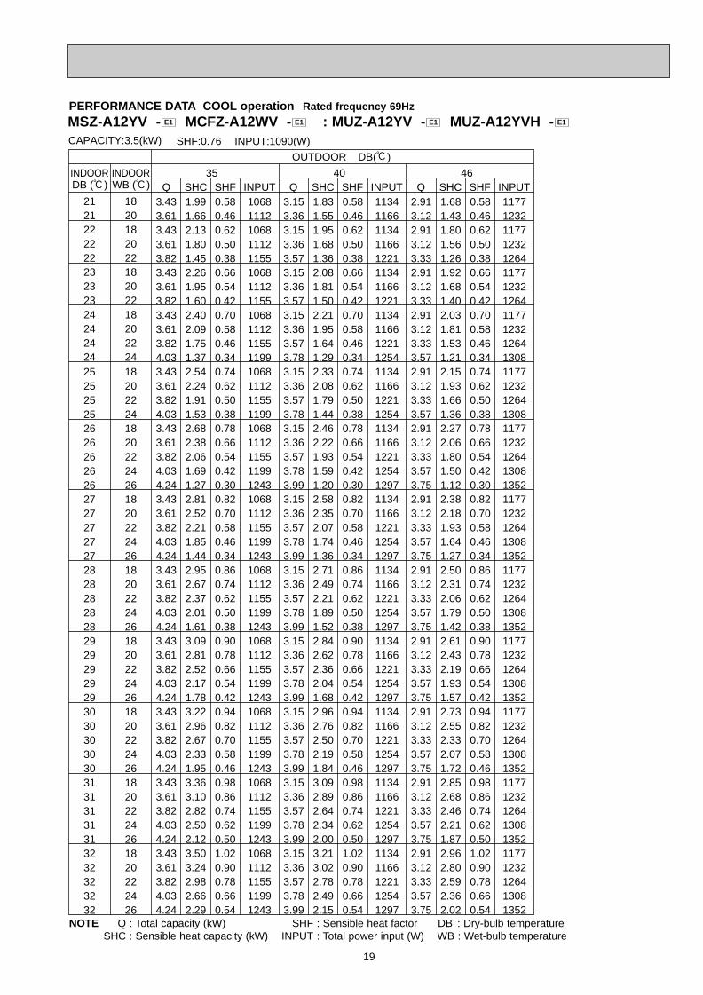
INDOOR INDOOR 35 40 46DB (:)
OUTDOOR DB(:)
CAPACITY:3.5(kW) INPUT:1090(W)SHF:0.76
WB (:)
21 1821 2022 1822 2022 2223 1823 2023 2224 1824 2024 2224 24
25 2025 2225 2426 1826 2026 2226 2426 2627 1827 2027 2227 2427 2628 1828 2028 2228 2428 2629 1829 2029 2229 2429 2630 1830 2030 2230 2430 2631 1831 2031 2231 2431 2632 1832 2032 2232 2432 26
Q SHC SHF INPUT Q SHC SHF INPUT Q SHC SHF INPUT3.43 1.99 0.58 1068 3.15 1.83 0.58 1134 2.91 1.68 0.58 11773.61 1.66 0.46 1112 3.36 1.55 0.46 1166 3.12 1.43 0.46 12323.43 2.13 0.62 1068 3.15 1.95 0.62 1134 2.91 1.80 0.62 11773.61 1.80 0.50 1112 3.36 1.68 0.50 1166 3.12 1.56 0.50 12323.82 1.45 0.38 1155 3.57 1.36 0.38 1221 3.33 1.26 0.38 12643.43 2.26 0.66 1068 3.15 2.08 0.66 1134 2.91 1.92 0.66 11773.61 1.95 0.54 1112 3.36 1.81 0.54 1166 3.12 1.68 0.54 12323.82 1.60 0.42 1155 3.57 1.50 0.42 1221 3.33 1.40 0.42 12643.43 2.40 0.70 1068 3.15 2.21 0.70 1134 2.91 2.03 0.70 11773.61 2.09 0.58 1112 3.36 1.95 0.58 1166 3.12 1.81 0.58 12323.82 1.75 0.46 1155 3.57 1.64 0.46 1221 3.33 1.53 0.46 12644.03 1.37 0.34 1199 3.78 1.29 0.34 1254 3.57 1.21 0.34 1308
25 18 3.43 2.54 0.74 1068 3.15 2.33 0.74 1134 2.91 2.15 0.74 11773.61 2.24 0.62 1112 3.36 2.08 0.62 1166 3.12 1.93 0.62 12323.82 1.91 0.50 1155 3.57 1.79 0.50 1221 3.33 1.66 0.50 12644.03 1.53 0.38 1199 3.78 1.44 0.38 1254 3.57 1.36 0.38 13083.43 2.68 0.78 1068 3.15 2.46 0.78 1134 2.91 2.27 0.78 11773.61 2.38 0.66 1112 3.36 2.22 0.66 1166 3.12 2.06 0.66 12323.82 2.06 0.54 1155 3.57 1.93 0.54 1221 3.33 1.80 0.54 12644.03 1.69 0.42 1199 3.78 1.59 0.42 1254 3.57 1.50 0.42 13084.24 1.27 0.30 1243 3.99 1.20 0.30 1297 3.75 1.12 0.30 13523.43 2.81 0.82 1068 3.15 2.58 0.82 1134 2.91 2.38 0.82 11773.61 2.52 0.70 1112 3.36 2.35 0.70 1166 3.12 2.18 0.70 12323.82 2.21 0.58 1155 3.57 2.07 0.58 1221 3.33 1.93 0.58 12644.03 1.85 0.46 1199 3.78 1.74 0.46 1254 3.57 1.64 0.46 13084.24 1.44 0.34 1243 3.99 1.36 0.34 1297 3.75 1.27 0.34 13523.43 2.95 0.86 1068 3.15 2.71 0.86 1134 2.91 2.50 0.86 11773.61 2.67 0.74 1112 3.36 2.49 0.74 1166 3.12 2.31 0.74 12323.82 2.37 0.62 1155 3.57 2.21 0.62 1221 3.33 2.06 0.62 12644.03 2.01 0.50 1199 3.78 1.89 0.50 1254 3.57 1.79 0.50 13084.24 1.61 0.38 1243 3.99 1.52 0.38 1297 3.75 1.42 0.38 13523.43 3.09 0.90 1068 3.15 2.84 0.90 1134 2.91 2.61 0.90 11773.61 2.81 0.78 1112 3.36 2.62 0.78 1166 3.12 2.43 0.78 12323.82 2.52 0.66 1155 3.57 2.36 0.66 1221 3.33 2.19 0.66 12644.03 2.17 0.54 1199 3.78 2.04 0.54 1254 3.57 1.93 0.54 13084.24 1.78 0.42 1243 3.99 1.68 0.42 1297 3.75 1.57 0.42 13523.43 3.22 0.94 1068 3.15 2.96 0.94 1134 2.91 2.73 0.94 11773.61 2.96 0.82 1112 3.36 2.76 0.82 1166 3.12 2.55 0.82 12323.82 2.67 0.70 1155 3.57 2.50 0.70 1221 3.33 2.33 0.70 12644.03 2.33 0.58 1199 3.78 2.19 0.58 1254 3.57 2.07 0.58 13084.24 1.95 0.46 1243 3.99 1.84 0.46 1297 3.75 1.72 0.46 13523.43 3.36 0.98 1068 3.15 3.09 0.98 1134 2.91 2.85 0.98 11773.61 3.10 0.86 1112 3.36 2.89 0.86 1166 3.12 2.68 0.86 12323.82 2.82 0.74 1155 3.57 2.64 0.74 1221 3.33 2.46 0.74 12644.03 2.50 0.62 1199 3.78 2.34 0.62 1254 3.57 2.21 0.62 13084.24 2.12 0.50 1243 3.99 2.00 0.50 1297 3.75 1.87 0.50 13523.43 3.50 1.02 1068 3.15 3.21 1.02 1134 2.91 2.96 1.02 11773.61 3.24 0.90 1112 3.36 3.02 0.90 1166 3.12 2.80 0.90 12323.82 2.98 0.78 1155 3.57 2.78 0.78 1221 3.33 2.59 0.78 12644.03 2.66 0.66 1199 3.78 2.49 0.66 1254 3.57 2.36 0.66 13084.24 2.29 0.54 1243 3.99 2.15 0.54 1297 3.75 2.02 0.54 1352
PERFORMANCE DATA COOL operation Rated frequency 69Hz
NOTE Q : Total capacity (kW) SHF : Sensible heat factor DB : Dry-bulb temperatureSHC : Sensible heat capacity (kW) INPUT : Total power input (W) WB : Wet-bulb temperature
MSZ-A12YV - MCFZ-A12WV - : MUZ-A12YV - MUZ-A12YVH - E1E1E1E1
OB328 A--1qxp 04.4.26 4:49 PM Page 19
20
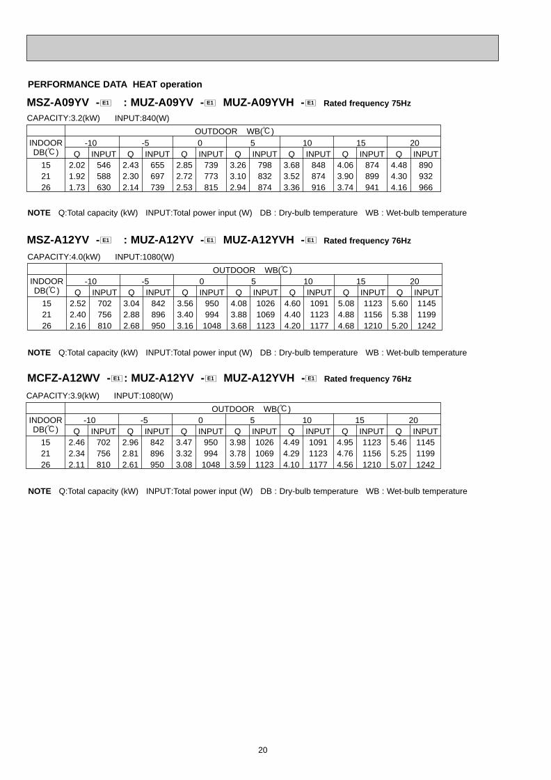
PERFORMANCE DATA HEAT operation
CAPACITY:3.2(kW) INPUT:840(W)
OUTDOOR WB(:)INDOOR -10 -5 0 5 10 15 20DB(:) Q INPUT Q INPUT Q INPUT Q INPUT Q INPUT Q INPUT Q INPUT
15 2.02 546 2.43 655 2.85 739 3.26 798 3.68 848 4.06 874 4.48 89021 1.92 588 2.30 697 2.72 773 3.10 832 3.52 874 3.90 899 4.30 93226 1.73 630 2.14 739 2.53 815 2.94 874 3.36 916 3.74 941 4.16 966
CAPACITY:4.0(kW) INPUT:1080(W)
OUTDOOR WB(:)INDOOR -10 -5 0 5 10 15 20DB(:) Q INPUT Q INPUT Q INPUT Q INPUT Q INPUT Q INPUT Q INPUT
15 2.52 702 3.04 842 3.56 950 4.08 1026 4.60 1091 5.08 1123 5.60 114521 2.40 756 2.88 896 3.40 994 3.88 1069 4.40 1123 4.88 1156 5.38 119926 2.16 810 2.68 950 3.16 1048 3.68 1123 4.20 1177 4.68 1210 5.20 1242
MSZ-A09YV - : MUZ-A09YV - MUZ-A09YVH - Rated frequency 75HzE1E1E1
MSZ-A12YV - : MUZ-A12YV - MUZ-A12YVH - Rated frequency 76HzE1E1E1
NOTE Q:Total capacity (kW) INPUT:Total power input (W) DB : Dry-bulb temperature WB : Wet-bulb temperature
CAPACITY:3.9(kW) INPUT:1080(W)
OUTDOOR WB(:)INDOOR -10 -5 0 5 10 15 20DB(:) Q INPUT Q INPUT Q INPUT Q INPUT Q INPUT Q INPUT Q INPUT
15 2.46 702 2.96 842 3.47 950 3.98 1026 4.49 1091 4.95 1123 5.46 114521 2.34 756 2.81 896 3.32 994 3.78 1069 4.29 1123 4.76 1156 5.25 119926 2.11 810 2.61 950 3.08 1048 3.59 1123 4.10 1177 4.56 1210 5.07 1242
MCFZ-A12WV - : MUZ-A12YV - MUZ-A12YVH - Rated frequency 76HzE1E1E1
NOTE Q:Total capacity (kW) INPUT:Total power input (W) DB : Dry-bulb temperature WB : Wet-bulb temperature
NOTE Q:Total capacity (kW) INPUT:Total power input (W) DB : Dry-bulb temperature WB : Wet-bulb temperature
OB328 A--1qxp 04.4.26 4:49 PM Page 20
21
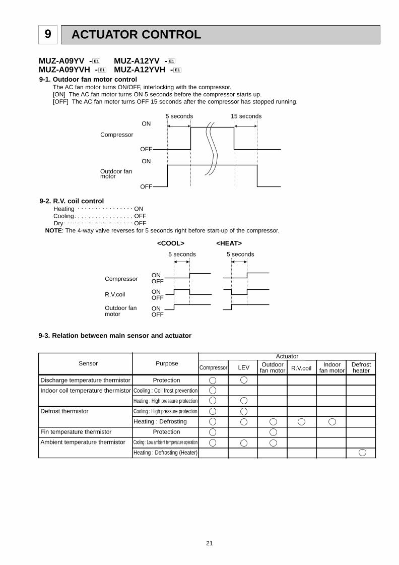
ACTUATOR CONTROL9
MUZ-A09YV - MUZ-A12YV -MUZ-A09YVH - MUZ-A12YVH - E1E1
E1E1
Discharge temperature thermistor
Indoor coil temperature thermistor
Defrost thermistor
Fin temperature thermistor
Ambient temperature thermistor
Purpose
Protection
Cooling : Coil frost prevention
Heating : High pressure protection
Cooling : High pressure protection
Heating : Defrosting
Protection
Cooling : Low ambient temperature operation
Heating : Defrosting (Heater)
Compressor LEV Outdoor fan motor
Indoor fan motor
DefrostheaterR.V.coil
SensorActuator
9-3. Relation between main sensor and actuator
9-2. R.V. coil controlHeating . . . . . . . . . . . . . . . . ONCooling. . . . . . . . . . . . . . . . . OFFDry. . . . . . . . . . . . . . . . . . . . OFF
NOTE: The 4-way valve reverses for 5 seconds right before start-up of the compressor.
ON
OFF
ON
OFF
Outdoor fanmotor
Compressor
5 seconds 15 seconds
ONOFFCompressor
Outdoor fanmotor
R.V.coil ONOFF
ONOFF
<COOL>
5 seconds
<HEAT>
5 seconds
9-1. Outdoor fan motor controlThe AC fan motor turns ON/OFF, interlocking with the compressor.[ON] The AC fan motor turns ON 5 seconds before the compressor starts up.[OFF] The AC fan motor turns OFF 15 seconds after the compressor has stopped running.
OB328 A--1qxp 04.4.26 4:49 PM Page 21
22
10 SERVICE FUNCTIONS
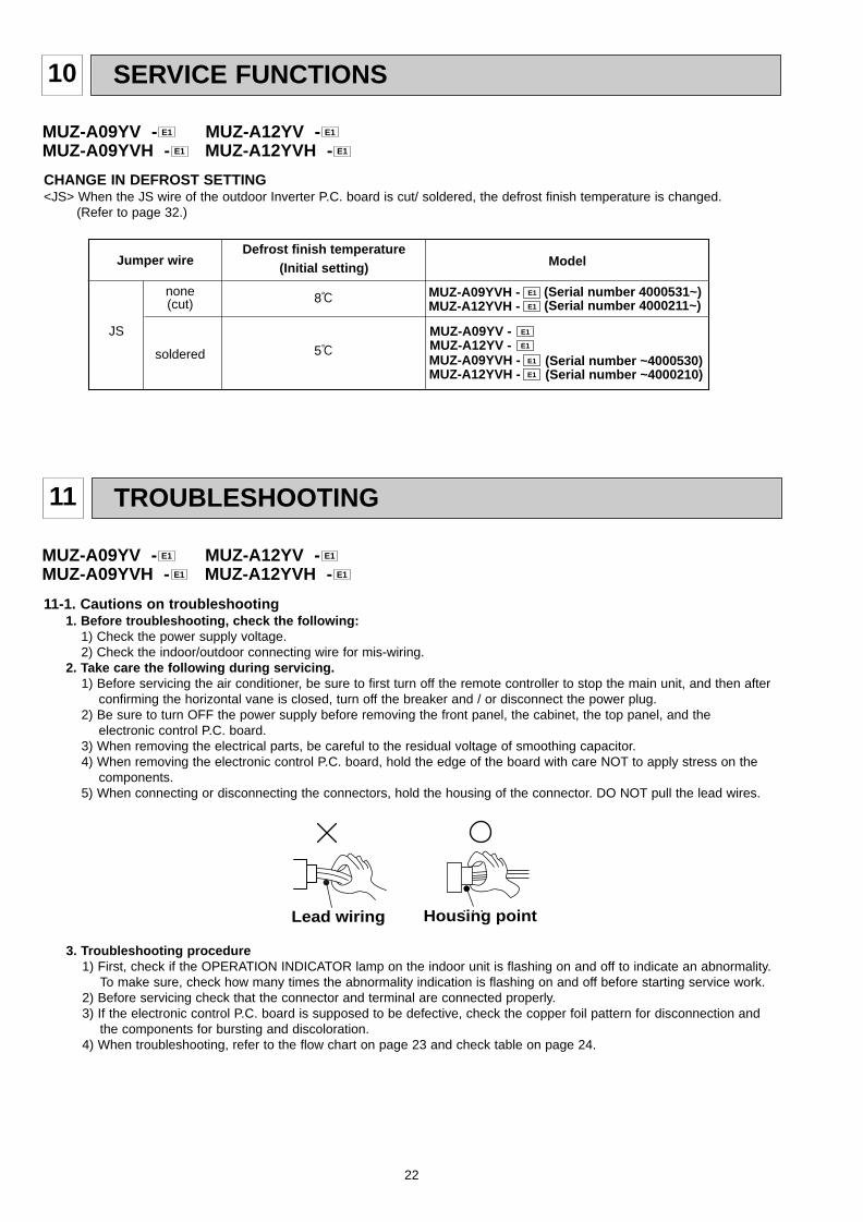
CHANGE IN DEFROST SETTING<JS> When the JS wire of the outdoor Inverter P.C. board is cut/ soldered, the defrost finish temperature is changed.
(Refer to page 32.)
Jumper wireDefrost finish temperature
(Initial setting)
JS
none(cut)
Model
soldered
MUZ-A09YVH - E1
E1 MUZ-A12YVH -(Serial number 4000531~) (Serial number 4000211~)
MUZ-A09YV - E1
E1 MUZ-A12YV -MUZ-A09YVH - E1
E1 MUZ-A12YVH -(Serial number ~4000530) (Serial number ~4000210)
8:
5:
MUZ-A09YV - MUZ-A12YV -MUZ-A09YVH - MUZ-A12YVH - E1E1
E1E1
11 TROUBLESHOOTING
3. Troubleshooting procedure1) First, check if the OPERATION INDICATOR lamp on the indoor unit is flashing on and off to indicate an abnormality.
To make sure, check how many times the abnormality indication is flashing on and off before starting service work.2) Before servicing check that the connector and terminal are connected properly.3) If the electronic control P.C. board is supposed to be defective, check the copper foil pattern for disconnection and
the components for bursting and discoloration.4) When troubleshooting, refer to the flow chart on page 23 and check table on page 24.
11-1. Cautions on troubleshooting1. Before troubleshooting, check the following:
1) Check the power supply voltage.2) Check the indoor/outdoor connecting wire for mis-wiring.
2. Take care the following during servicing.1) Before servicing the air conditioner, be sure to first turn off the remote controller to stop the main unit, and then after
confirming the horizontal vane is closed, turn off the breaker and / or disconnect the power plug.2) Be sure to turn OFF the power supply before removing the front panel, the cabinet, the top panel, and the
electronic control P.C. board.3) When removing the electrical parts, be careful to the residual voltage of smoothing capacitor. 4) When removing the electronic control P.C. board, hold the edge of the board with care NOT to apply stress on the
components.5) When connecting or disconnecting the connectors, hold the housing of the connector. DO NOT pull the lead wires.
Housing pointLead wiring
MUZ-A09YV - MUZ-A12YV -MUZ-A09YVH - MUZ-A12YVH - E1E1
E1E1
OB328 A--1qxp 04.4.26 4:49 PM Page 22
23
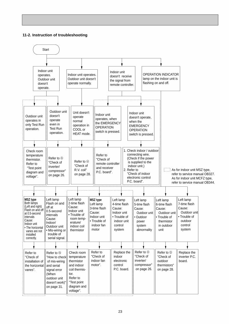
Start
Indoor unit operates.Outdoor unit doesn't operate.
Indoor unit doesn't receive the signal from remote controller.
OPERATION INDICATORlamp on the indoor unit is flashing on and off.
Outdoor unit operates in only Test Run operation.
Outdoor unit doesn't operate even in Test Run operation.
Indoor unit operates, when the EMERGENCY OPERATION switch is pressed.
Indoor unit doesn't operate, when the EMERGENCY OPERATION switch is pressed.
Check room temperature thermistor.Refer to "Test point diagram and voltage".
Refer to A"Check of inverter/compressor" on page 26.
Refer to "Check of remote controller and receiver P.C. board".
1. Check indoor / outdoor connecting wire. (Check if the power is supplied to the indoor unit.)2. Refer to "Check of indoor electronic control P.C. board".
Unit doesn't operate normaloperation in COOL or HEAT mode.
Refer to H "Check of R.V. coil"on page 28.
Left lampFlash on and off at 0.5-secondintervalsCause: Indoor/Outdoor unit• Mis-wiring or trouble of serial signal.
Left lamp2-time flash Cause:Indoor unit• Trouble of room temp- erature/ indoor coil thermistor
MSZ typeLeft lamp3-time flash Cause:Indoor unit• Trouble of indoor fan motor
Left lamp5-time flash Cause: Outdoor unit• Outdoor power system abnormality
Left lamp6-time flash Cause: Outdoor unit• Trouble of thermistor in outdoor unit
Left lamp7-time flash Cause: Outdoor unit• Trouble of outdoor control system
Refer to N
"How to check of mis-wiringand serial signal error (When outdoor unit doesn't work)"on page 31.
MSZ typeBoth lamps (Left and right)Flash on and off at 0.5-second intervals Cause:Indoor unit• The horizontal vanes are not installed correctly.
Refer to"Check of installation of the horizontalvanes".
Check room temperature thermistor and indoor coil thermis-tor.Refer to "Test point diagram and voltage".
Refer to "Check of indoor fan motor".
Refer to A "Check of inverter/ compressor" on page 26.
Refer to G "Check of outdoor thermistors"on page 28.
Replace the inverter P.C. board.
Left lamp4-time flash Cause:Indoor unit• Trouble of indoor unit control system
Replace the indoor electronic control P.C. board.
As for indoor unit MSZ type,refer to service manual OB327.As for indoor unit MCFZ type,refer to service manual OB344.
Indoor unit operates.Outdoor unit doesn'toperate normally.
11-2. Instruction of troubleshooting
OB328 A--1qxp 04.4.26 4:49 PM Page 23
24
ON
OFF2.5-second OFF 2.5-second OFF
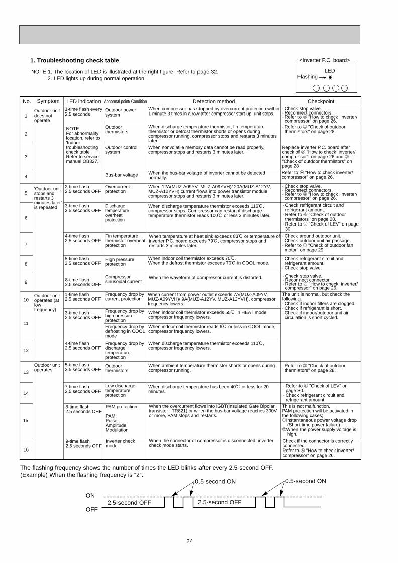
NOTE 1. The location of LED is illustrated at the right figure. Refer to page 32.2. LED lights up during normal operation.
The flashing frequency shows the number of times the LED blinks after every 2.5-second OFF.(Example) When the flashing frequency is “2”.
Abnormal point/ ConditionWhen compressor has stopped by overcurrent protection within 1 minute 3 times in a row after compressor start-up, unit stops.
When discharge temperature thermistor, fin temperature thermistor or defrost thermistor shorts or opens during compressor running, compressor stops and restarts 3 minutes later.When nonvolatile memory data cannot be read properly, compressor stops and restarts 3 minutes later.
When 12A(MUZ-A09YV, MUZ-A09YVH)/ 20A(MUZ-A12YV, MUZ-A12YVH) current flows into power transistor module, compressor stops and restarts 3 minutes later.
When discharge temperature thermistor exceeds 116:, compressor stops. Compressor can restart if discharge temperature thermistor reads 100: or less 3 minutes later.
When temperature at heat sink exceeds 83: or temperature of inverter P.C. board exceeds 79:, compressor stops and restarts 3 minutes later.
When indoor coil thermistor exceeds 70:. When the defrost thermistor exceeds 70: in COOL mode.
When current from power outlet exceeds 7A(MUZ-A09YV, MUZ-A09YVH)/ 9A(MUZ-A12YV, MUZ-A12YVH), compressor frequency lowers.
When indoor coil thermistor exceeds 55: in HEAT mode, compressor frequency lowers.
When indoor coil thermistor reads 6: or less in COOL mode, compressor frequency lowers.
When discharge temperature thermistor exceeds 110:,compressor frequency lowers.
When discharge temperature has been 40: or less for 20 minutes.
No.
1
2
3
5
6
7
8
10
11
12
14
15
Symptom LED indication Detection method Checkpoint
Outdoor unit does not operate
'Outdoor unit stops and restarts 3 minutes later' is repeated
Outdoor unit operates (at low frequency)
Outdoor unit operates
1-time flash every 2.5 seconds
NOTE: For abnormality location, refer to 'Indoor troubleshooting check table'. Refer to service manual OB327.
2-time flash 2.5 seconds OFF
3-time flash2.5 seconds OFF
4-time flash2.5 seconds OFF
5-time flash2.5 seconds OFF
1-time flash2.5 seconds OFF
3-time flash 2.5 seconds OFF
4-time flash2.5 seconds OFF
7-time flash2.5 seconds OFF
Outdoor power system
Outdoor thermistors
Outdoor control system
Overcurrent protection
Discharge temperature overheatprotection
Fin temperature thermistor overheat protection
High pressure protection
Frequency drop by current protection
Frequency drop by high pressure protection Frequency drop by defrosting in COOL mode
Frequency drop by discharge temperature protection
Low discharge temperature protection
· Check stop valve.· Reconnect connectors.· Refer to A "How to check inverter/
compressor" on page 26.· Refer to G "Check of outdoor
thermistors" on page 28.
· Check stop valve.· Reconnect connectors.· Refer to A "How to check inverter/ compressor" on page 26.
Replace inverter P.C. board after check of A "How to check inverter/compressor" on page 26 and G "Check of outdoor thermistors" on page 28.
· Check refrigerant circuit and refrigerant amount.
· Refer to G "Check of outdoor thermistors" on page 28.
· Refer to L "Check of LEV" on page 30.
· Check around outdoor unit.· Check outdoor unit air passage.· Refer to I "Check of outdoor fan
motor" on page 29.
· Check refrigerant circuit and refrigerant amount.
· Check stop valve.
The unit is normal, but check the following.· Check if indoor filters are clogged. · Check if refrigerant is short.· Check if indoor/outdoor unit air
circulation is short cycled.
· Refer to L "Check of LEV" on page 30.
· Check refrigerant circuit and refrigerant amount.
<Inverter P.C. board>
LEDFlashing
Refer to A "How to check inverter/ compressor" on page 26.
When the bus-bar voltage of inverter cannot be detected normally.Bus-bar voltage
8-time flash2.5 seconds OFF
Compressor sinusoidal current
When the waveform of compressor current is distorted. · Check stop valve.· Reconnect connector.· Refer to A "How to check inverter/ compressor" on page 26.
8-time flash2.5 seconds OFF
PAM protection
PAM:Pulse Amplitude Modulation
When the overcurrent flows into IGBT(Insulated Gate Bipolar transistor : TR821) or when the bus-bar voltage reaches 300V or more, PAM stops and restarts.
This is not malfunction.PAM protection will be activated inthe following cases;1Instantaneous power voltage drop (Short time power failure)2When the power supply voltage is high.
9-time flash2.5 seconds OFF
Inverter check mode
When the connector of compressor is disconnected, inverter check mode starts.
Check if the connector is correctly connected.Refer to A "How to check inverter/ compressor" on page 26.
4
9
16
13
When ambient temperature thermistor shorts or opens during compressor running.
5-time flash2.5 seconds OFF
Outdoor thermistors
· Refer to G "Check of outdoor thermistors" on page 28.
0.5-second ON 0.5-second ON
1. Troubleshooting check table
OB328 A--1qxp 04.4.26 4:49 PM Page 24
25
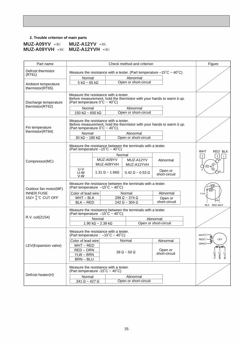
2. Trouble criterion of main parts
Part name FigureCheck method and criterion
Outdoor fan motor(MF)INNER FUSE152i : CUT OFF0
5
R.V. coil(21S4)
LEV(Expansion valve)
Measure the resistance between the terminals with a tester.(Part temperature –15˚C ~ 40˚C)
WHT – BLKBLK – RED
AbnormalOpen or
short-circuit
Normal
Measure the resistance between the terminals with a tester.(Part temperature –15˚C ~ 40˚C)
Normal1.90 k" ~ 2.39 k"
AbnormalOpen or short-circuit
WHT – REDRED – ORNYLW – BRNBRN – BLU
Abnormal
Open orshort-circuit
Normal
39 " ~ 50 "
Measure the resistance with a tester.(Part temperature : –15˚C ~ 40˚C)
Measure the resistance with a tester. (Part temperature –15˚C ~ 40˚C)
Color of lead wire
Color of lead wire
Discharge temperaturethermistor(RT62)
Measure the resistance with a tester. Before measurement, hold the thermistor with your hands to warm it up.(Part temperature 0˚C ~ 40˚C)
Normal150 k" ~ 600 k"
30 k" ~ 180 k"
AbnormalOpen or short-circuit
Normal5 k" ~ 65 k"
AbnormalOpen or short-circuit
Defrost thermistor(RT61)
Fin temperaturethermistor(RT64)
Measure the resistance with a tester. Before measurement, hold the thermistor with your hands to warm it up.(Part temperature 0˚C ~ 40˚C)
Normal AbnormalOpen or short-circuit
Ambient temperaturethermistor(RT65)
WHTREDBLK
299 " ~ 374 "242 " ~ 304 "
Measure the resistance between the terminals with a tester. (Part temperature –15˚C ~ 40˚C)
Compressor(MC)
Defrost heater(H)
Measure the resistance with a tester. (Part temperature -15˚C ~ 40˚C)
Normal341 " ~ 427 "
AbnormalOpen or short-circuit
U-VU-WV-W
Abnormal
Open orshort-circuit
NormalMUZ-A12YV
MUZ-A12YVH
0.42 " ~ 0.53 "
MUZ-A09YVMUZ-A09YVH
1.31 " ~ 1.66"
2 3
W
UV
1
WHT RED BLK
FUSE
LEV
WHT6
RED1
ORN4
YLW
5
BR
N2
BLU
3
MUZ-A09YV - MUZ-A12YV -MUZ-A09YVH - MUZ-A12YVH - E1E1
E1E1
OB328 A--1qxp 04.4.26 4:49 PM Page 25
26
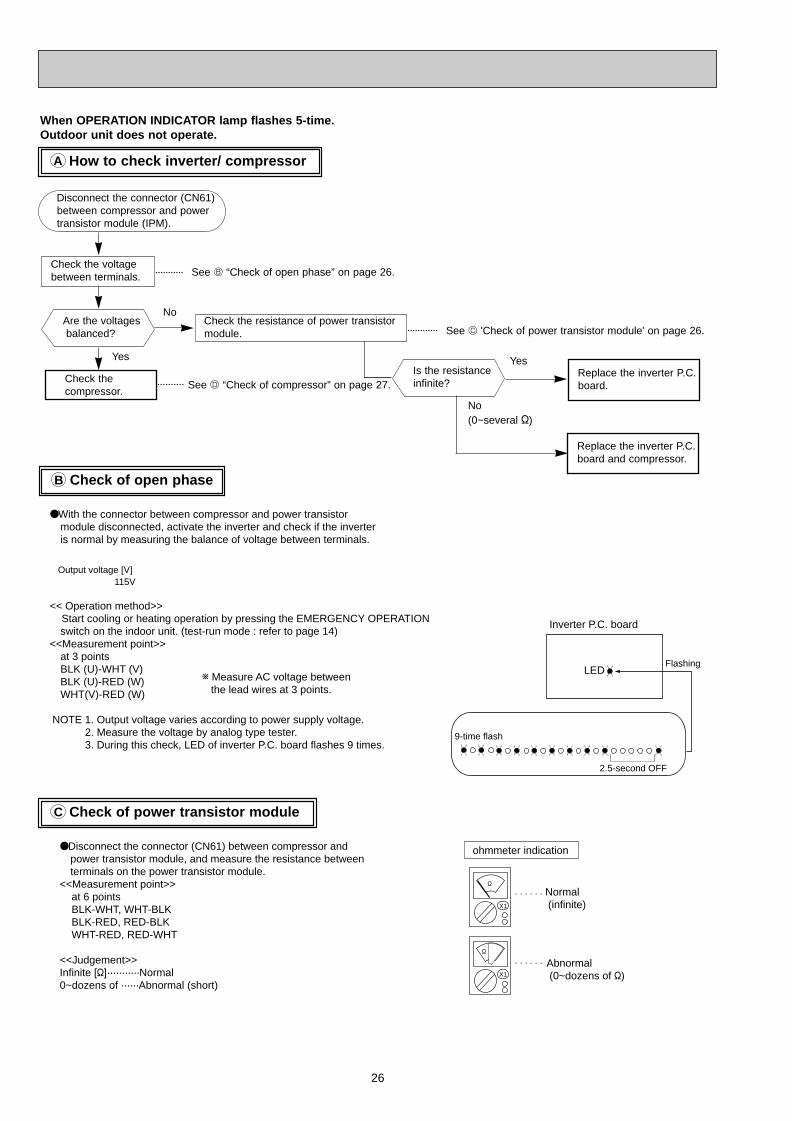
Check of open phaseB
Check of power transistor moduleC
How to check inverter/ compressorA
When OPERATION INDICATOR lamp flashes 5-time.Outdoor unit does not operate.
Check the voltagebetween terminals.
Check thecompressor.
Disconnect the connector (CN61)between compressor and powertransistor module (IPM).
Check the resistance of power transistormodule.
See D “Check of compressor” on page 27.
No
See B “Check of open phase” on page 26.
See C 'Check of power transistor module' on page 26.
Is the resistanceinfinite?
YesReplace the inverter P.C.board.
No (0~several ")
Yes
Are the voltagesbalanced?
Replace the inverter P.C.board and compressor.
●With the connector between compressor and power transistor module disconnected, activate the inverter and check if the inverter is normal by measuring the balance of voltage between terminals.
<< Operation method>> Start cooling or heating operation by pressing the EMERGENCY OPERATION
switch on the indoor unit. (test-run mode : refer to page 14)<<Measurement point>>
at 3 pointsBLK (U)-WHT (V)BLK (U)-RED (W) WHT(V)-RED (W)
NOTE 1. Output voltage varies according to power supply voltage. 2. Measure the voltage by analog type tester. 3. During this check, LED of inverter P.C. board flashes 9 times.
●Disconnect the connector (CN61) between compressor and power transistor module, and measure the resistance between terminals on the power transistor module.
<<Measurement point>> at 6 points BLK-WHT, WHT-BLK BLK-RED, RED-BLK WHT-RED, RED-WHT <<Judgement>>Infinite ["]···········Normal 0~dozens of ······Abnormal (short)
Output voltage [V] 115V
w Measure AC voltage between the lead wires at 3 points.
ohmmeter indication
Normal (infinite)
Abnormal (0~dozens of ")X1
"
X1
"
LED
Inverter P.C. board
9-time flash
2.5-second OFF
Flashing
OB328 A--1qxp 04.4.26 4:49 PM Page 26
27
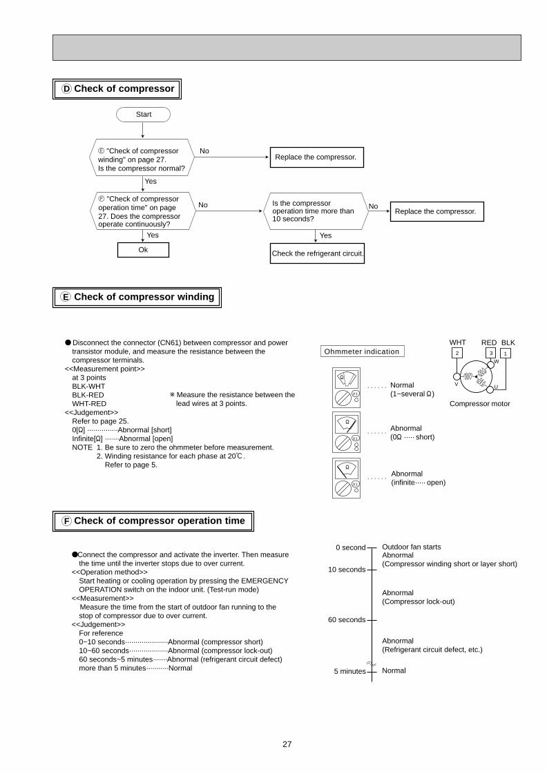
Check of compressorD
Check of compressor windingE
Check of compressor operation timeF
● Disconnect the connector (CN61) between compressor and power transistor module, and measure the resistance between the compressor terminals.
<<Measurement point>>at 3 points BLK-WHTBLK-REDWHT-RED
<<Judgement>>Refer to page 25.0["] ···············Abnormal [short]Infinite["] ·······Abnormal [open]NOTE 1. Be sure to zero the ohmmeter before measurement. 2. Winding resistance for each phase at 20:. Refer to page 5.
●Connect the compressor and activate the inverter. Then measure the time until the inverter stops due to over current.
<<Operation method>>Start heating or cooling operation by pressing the EMERGENCY OPERATION switch on the indoor unit. (Test-run mode)
<<Measurement>> Measure the time from the start of outdoor fan running to the
stop of compressor due to over current.<<Judgement>>
For reference0~10 seconds·····················Abnormal (compressor short)10~60 seconds···················Abnormal (compressor lock-out)60 seconds~5 minutes·······Abnormal (refrigerant circuit defect)more than 5 minutes···········Normal
w Measure the resistance between the lead wires at 3 points.
Outdoor fan startsAbnormal (Compressor winding short or layer short)
Abnormal(Compressor lock-out)
Abnormal(Refrigerant circuit defect, etc.)
Normal
0 second
10 seconds
60 seconds
5 minutes
Normal(1~several " )
Abnormal(0" ····· short)
Abnormal(infinite····· open)
Ohmmeter indication
Start
Ok
Replace the compressor.E "Check of compressor winding" on page 27.Is the compressor normal?
No
Replace the compressor.No
Yes
X1
"
X1
"
X1
"
2 3
W
UV
1
WHT
Compressor motor
RED BLK
Yes
F "Check of compressor operation time" on page 27. Does the compressor operate continuously?
Is the compressor operation time more than 10 seconds?
No
Check the refrigerant circuit.
Yes
OB328 A--1qxp 04.4.26 4:49 PM Page 27
28
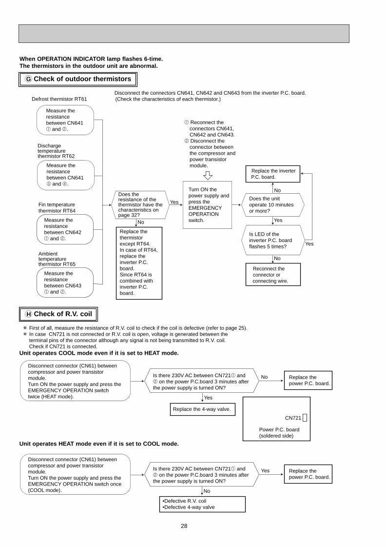
Check of outdoor thermistorsG
When OPERATION INDICATOR lamp flashes 6-time.The thermistors in the outdoor unit are abnormal.
Measure the resistance between CN641 1 and 2.
Measure the resistance between CN642 1 and 2.
No
Yes
Replace the thermistor except RT64.In case of RT64, replace the inverter P.C. board.Since RT64 is combined with inverter P.C. board.
Replace the inverter P.C. board.
Disconnect the connectors CN641, CN642 and CN643 from the inverter P.C. board.(Check the characteristics of each thermistor.)
1 Reconnect the connectors CN641, CN642 and CN643.
2 Disconnect the connector between the compressor and power transistor module.
Defrost thermistor RT61
Measure the resistance between CN641 3 and 4.
Turn ON the power supply and press the EMERGENCY OPERATION switch.
Discharge temperature thermistor RT62
Fin temperature thermistor RT64
Does the resistance of the thermistor have the characteristics on page 32?
No
Yes
Does the unit operate 10 minutes or more?
Is LED of the inverter P.C. board flashes 5 times?
Reconnect the connector or
connecting wire.
Yes
No
Measure the resistance between CN643 1 and 2.
Ambient temperature thermistor RT65
Check of R.V. coilH
Disconnect connector (CN61) between compressor and power transistor module.Turn ON the power supply and press the EMERGENCY OPERATION switch twice (HEAT mode).
Is there 230V AC between CN7211 and 2 on the power P.C.board 3 minutes after the power supply is turned ON?
Yes
No Replace the power P.C. board.
Replace the 4-way valve.
Disconnect connector (CN61) between compressor and power transistor module.Turn ON the power supply and press the EMERGENCY OPERATION switch once (COOL mode).
Is there 230V AC between CN7211 and 2 on the power P.C.board 3 minutes after the power supply is turned ON?
No
Yes Replace the power P.C. board.
•Defective R.V. coil•Defective 4-way valve
w First of all, measure the resistance of R.V. coil to check if the coil is defective (refer to page 25).w In case CN721 is not connected or R.V. coil is open, voltage is generated between the terminal pins of the connector although any signal is not being transmitted to R.V. coil. Check if CN721 is connected.
CN721
Power P.C. board(soldered side)
Unit operates COOL mode even if it is set to HEAT mode.
Unit operates HEAT mode even if it is set to COOL mode.
OB328 A--1qxp 04.4.26 4:49 PM Page 28
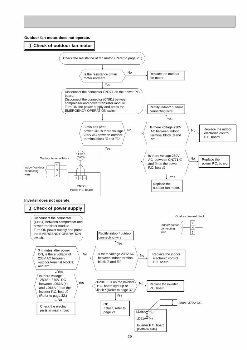
29
Check of power supplyJ
Inverter does not operate.
Check of outdoor fan motorI
Outdoor fan motor does not operate.
Is there voltage 230V AC between indoor terminal block 2 and N?
Replace the outdoor fan motor.
3 minutes after power ON, is there voltage 230V AC between outdoor terminal block 2 and N?
Is the resistance of fan motor normal?
Is there voltage 230V AC between CN771 2 and 3 on the power P.C. board?
Disconnect the connector CN771 on the power P.C. board.Disconnect the connector (CN61) between compressor and power transistor module.Turn ON the power supply and press the EMERGENCY OPERATION switch.
Yes
Yes
Yes
No
No
CN771Power P.C. board
1 2 3
FanmotorOutdoor terminal block
3
N
2
Check the resistance of fan motor. (Refer to page 25.)
Replace the power P.C. board.
Rectify indoor/ outdoor connecting wire.
No
Replace the indoor electronic control P.C. board.
Replace the outdoorfan motor.
No
Yes
Indoor/ outdoorconnectingwire
Disconnect the connector(CN61) between compressor and power transistor module.Turn ON power supply and press the EMERGENCY OPERATION switch.
Check the electric parts in main circuit.
Ok.If flash, refer to page 24.
3 minutes after power ON, is there voltage of 230V AC between outdoor terminal block 2
and N?
Is there voltage 280V ~ 370V DC between LD61A (+) and LD66A (–) on the inverter P.C. board?(Refer to page 32.)
Dose LED on the inverter P.C. board light up or flash? (Refer to page 32.)
Outdoor terminal block
3
N
2
Yes
Yes
Yes
No
No
Replace the indoor electronic control P.C. board.
No
Yes
No
Indoor/ outdoorconnectingwire
Replace the inverter P.C. board.
LD66A
LD61A
(–)
(+)
280V~370V DC
Inverter P.C. board(Pattern side)
Is there voltage 230V AC between indoor terminal block 2 and N?
Rectify indoor/ outdoor connecting wire.
OB328 A--1qxp 04.4.26 4:49 PM Page 29
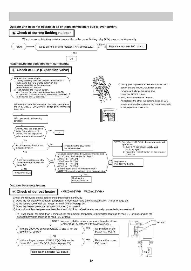
30
Check of LEV (Expansion valve)
Check of current-limiting resistorK
Outdoor unit does not operate at all or stops immediately due to over current.
Replace the power P.C. board.
When the current-limiting resistor is open, the rush current limiting relay (X64) may not work properly.
Does current-limiting resistor (R64) detect 10"?No ∞
Yes
Ok
Start
L
Heating/Cooling does not work sufficiently.
Replace the LEV.
With remote controller set toward the indoor unit, press the OPERATE/ STOP(ON/ OFF) button and confirm one beep tone.
LEV operates in full-opening direction.
Is LEV properly fixed to the expansion valve?
Ok
Do you hear the expansion valve "click, click·······"?Do you feel the expansion valve vibrate on touching it ?
Does the resistance of LEV have the characteristics on page 25?
Measure each voltage between connector pins of CN724 on the inverter P.C. board.1.Pin3(-) Pin1(+)2.Pin4(-) Pin1(+)3.Pin5(-) Pin1(+)4.Pin6(-) Pin1(+)Is there about 3~5V AC between each?NOTE: Measure the voltage by an analog tester.
No
Yes
Yes
Yes
No
Replace the expansion valve.
Yes
No
NoProperly fix the LEV to the expansion valve.
Replace the inverter P.C. board.
NOTE : After check of LEV, do the undermentioned operations.
1. Turn OFF the power supply and turn ON again.
2. Press the RESET button on the remote controller.
Turn ON the power supply.1 During pressing both the OPERATION SELECT button and the TOO COOL button on the
remote controller at the same time, press the RESET button.2 First, release the RESET button. And release the other two buttons since all LCD in operation display section of the remote controller is displayed after 3 seconds.
1 During pressing both the OPERATION SELECT
button and the TOO COOL button on the
remote controller at the same time,
press the RESET button.
2 First, release the RESET button.
And release the other two buttons since all LCD
in operation display section of the remote controller
is displayed after 3 seconds.
AMPMCLOCK
:
AMPM
Check of defrost heaterM
Replace the inverter P.C. board.
Is there 230V AC between CN722 1 and 3 on the power P.C. board?
Yes
No
No problem of the power P.C. board.
Is the voltage between CN726 6(+)-3(-) on the power P.C. board 0V DC? (Refer to page 33.)
Yes
No
Replace the power P.C. board.
NOTE: In case both thermistors are more than the above temperature, cool them with cold water etc...
In HEAT mode, for more than 5 minutes, let the ambient temperature thermistor continue to read 5: or less, and let the defrost thermistor continue to read -1: or less.
321
230V AC
Check the following points before checking electric continuity.1) Does the resistance of ambient temperature thermistor have the characteristics? (Refer to page 32.)2) Is the resistance of defrost heater normal? (Refer to page 25.)3) Does the heater protector remain conducted (not open)?4) Are both ambient temperature thermistor and circuit of defrost heater securely connected to connectors?
26H
CN726
CN722
H
2121
3 6
Outdoor base gets frozen.
<MUZ-A09YVH MUZ-A12YVH>
OB328 A--1qxp 04.4.26 4:49 PM Page 30
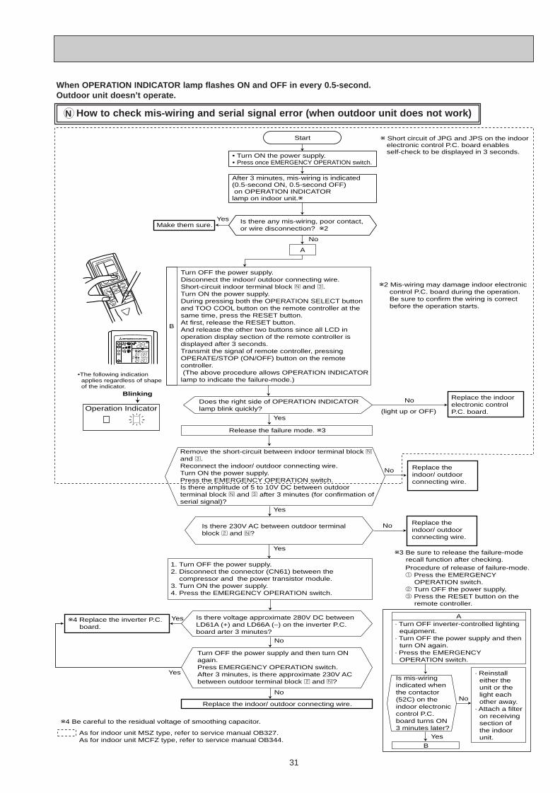
31
When OPERATION INDICATOR lamp flashes ON and OFF in every 0.5-second.Outdoor unit doesn’t operate.
No Replace the indoor/ outdoor connecting wire.
Is there voltage approximate 280V DC between LD61A (+) and LD66A (–) on the inverter P.C. board arter 3 minutes?
Turn OFF the power supply and then turn ON again.Press EMERGENCY OPERATION switch.After 3 minutes, is there approximate 230V AC between outdoor terminal block 2 and N?
w4 Replace the inverter P.C. board.
Does the right side of OPERATION INDICATOR lamp blink quickly?
w2 Mis-wiring may damage indoor electronic control P.C. board during the operation. Be sure to confirm the wiring is correct before the operation starts.
Replace the indoor electronic control P.C. board.
No
Replace the indoor/ outdoor connecting wire.
Release the failure mode. w3
Yes
Yes
A
B
Turn OFF the power supply.Disconnect the indoor/ outdoor connecting wire.Short-circuit indoor terminal block N and 3.Turn ON the power supply.During pressing both the OPERATION SELECT button and TOO COOL button on the remote controller at the same time, press the RESET button.At first, release the RESET button.And release the other two buttons since all LCD in operation display section of the remote controller is displayed after 3 seconds.Transmit the signal of remote controller, pressing OPERATE/STOP (ON/OFF) button on the remote controller. (The above procedure allows OPERATION INDICATOR lamp to indicate the failure-mode.)
Remove the short-circuit between indoor terminal block N and 3.Reconnect the indoor/ outdoor connecting wire.Turn ON the power supply.Press the EMERGENCY OPERATION switch.Is there amplitude of 5 to 10V DC between outdoor terminal block N and 3 after 3 minutes (for confirmation of serial signal)?
1. Turn OFF the power supply.2. Disconnect the connector (CN61) between the
compressor and the power transistor module.3. Turn ON the power supply.4. Press the EMERGENCY OPERATION switch.
No
Yes
No
Yes
(light up or OFF)
Is mis-wiring indicated when the contactor(52C) on the indoor electronic control P.C. board turns ON 3 minutes later?
Yes
No
· Turn OFF inverter-controlled lighting equipment.
· Turn OFF the power supply and then turn ON again.
· Press the EMERGENCY OPERATION switch.
B
· Reinstall either the unit or the light each other away.
· Attach a filter on receiving section of the indoor unit.
w3 Be sure to release the failure-mode recall function after checking.
w4 Be careful to the residual voltage of smoothing capacitor.
Procedure of release of failure-mode.1 Press the EMERGENCY
OPERATION switch.2 Turn OFF the power supply.3 Press the RESET button on the
remote controller.
Start
No
• Turn ON the power supply.• Press once EMERGENCY OPERATION switch.
Is there any mis-wiring, poor contact, or wire disconnection? w2
Make them sure.Yes
After 3 minutes, mis-wiring is indicated(0.5-second ON, 0.5-second OFF) on OPERATION INDICATORlamp on indoor unit.w
w Short circuit of JPG and JPS on the indoor electronic control P.C. board enables self-check to be displayed in 3 seconds.
Yes
Is there 230V AC between outdoor terminal block 2 and N?
No Replace the indoor/ outdoor connecting wire.
A
•The following indication applies regardless of shape of the indicator.
Blinking
Operation Indicator
As for indoor unit MSZ type, refer to service manual OB327.As for indoor unit MCFZ type, refer to service manual OB344.
AMPMCLOCK
:
AMPM
How to check mis-wiring and serial signal error (when outdoor unit does not work)N
OB328A --2qxp 04.4.26 4:50 PM Page 31
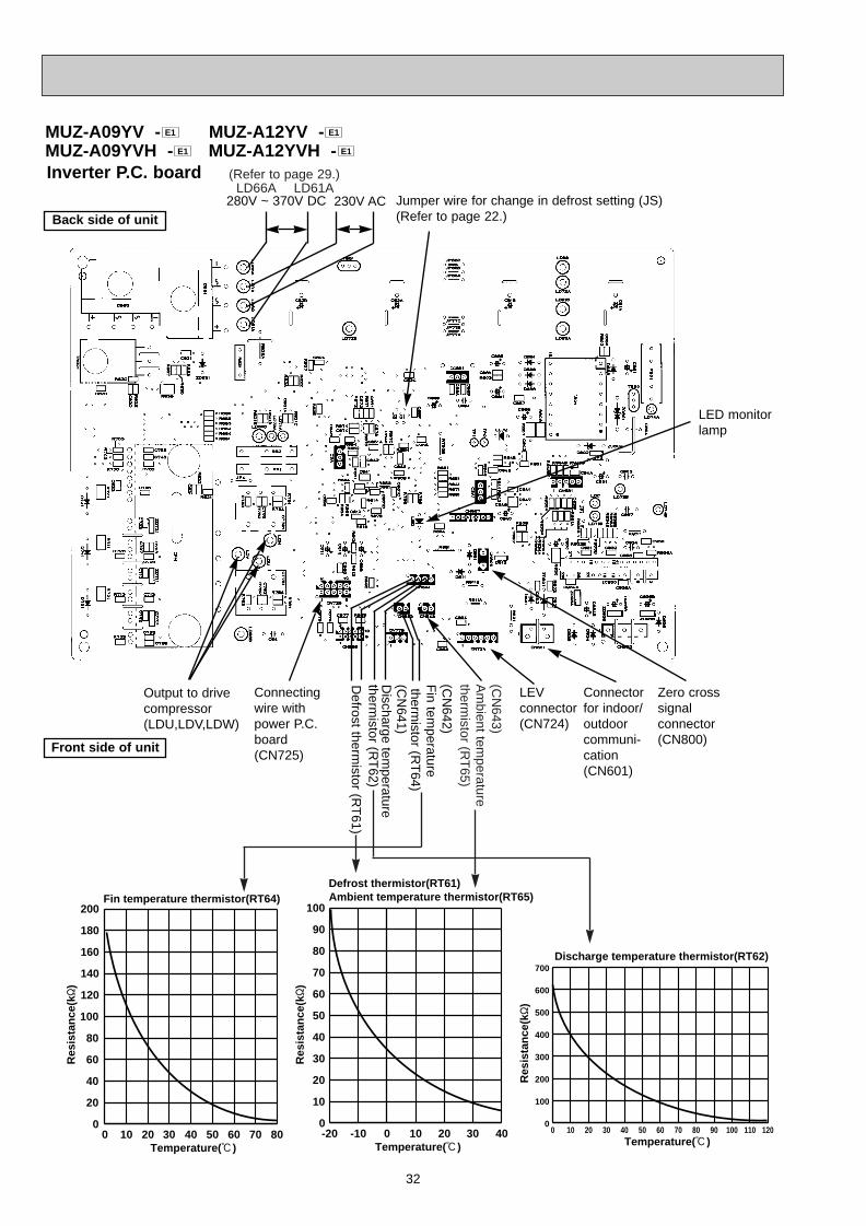
32
Inverter P.C. board
MUZ-A09YV - MUZ-A12YV -MUZ-A09YVH - MUZ-A12YVH - E1E1
E1E1
LED monitorlamp
Jumper wire for change in defrost setting (JS)(Refer to page 22.)
Zero crosssignal connector(CN800)
Connectorfor indoor/outdoorcommuni-cation(CN601)
LEVconnector(CN724)
Output to drivecompressor(LDU,LDV,LDW)
Connectingwire withpower P.C.board(CN725)
Defrost therm
istor (RT
61)
Discharge tem
peraturetherm
istor (RT
62)
(CN
641)
Fin tem
peraturetherm
istor (RT
64)
(CN
642)
Back side of unit
Front side of unit
280V ~ 370V DC 230V AC
-20 -10 0 10 20 30 400
10
20
30
40
50
60
70
80
90
100
Temperature(:)
Ambient temperature thermistor(RT65)Defrost thermistor(RT61)
Temperature(:)
Discharge temperature thermistor(RT62)
0 10 20 30 40 50 60 70 80 90 100 110 1200
100
200
300
400
500
600
700
0 10 20 30 40 50 60 70 800
20
40
60
80
100
120
140
160
180
200
Temperature(:)
Fin temperature thermistor(RT64)
Res
ista
nce
(k"
)
Res
ista
nce
(k"
)
Res
ista
nce
(k"
)
(CN
643)A
mbient tem
perature therm
istor (RT
65)
LD66A LD61A(Refer to page 29.)
OB328A --2qxp 04.4.26 4:50 PM Page 32
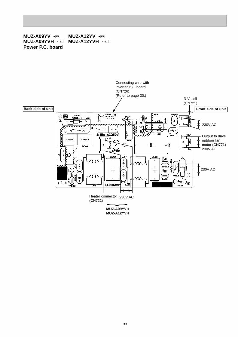
33
Power P.C. board
Connecting wire withinverter P.C. board(CN726)(Refer to page 30.)
230V AC
R.V. coil (CN721)
Output to driveoutdoor fan motor (CN771)230V AC
Heater connector(CN722)
230V AC
230V AC
Back side of unit
MUZ-A09YVHMUZ-A12YVH
}
MUZ-A09YV - MUZ-A12YV -MUZ-A09YVH - MUZ-A12YVH - E1E1
E1E1
Front side of unit
OB328A --2qxp 04.4.26 4:50 PM Page 33
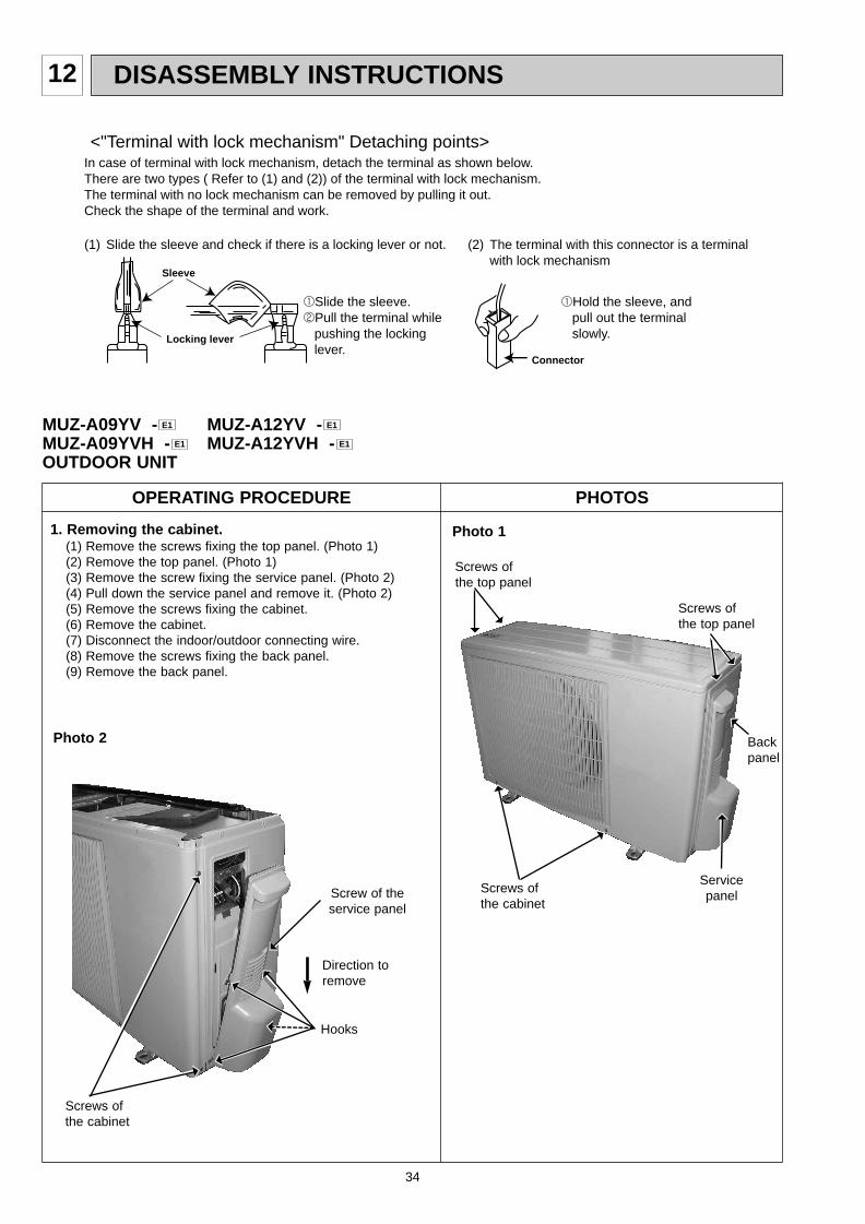
34
12 DISASSEMBLY INSTRUCTIONS
OPERATING PROCEDURE PHOTOS
Photo 11. Removing the cabinet.(1) Remove the screws fixing the top panel. (Photo 1)(2) Remove the top panel. (Photo 1)(3) Remove the screw fixing the service panel. (Photo 2)(4) Pull down the service panel and remove it. (Photo 2)(5) Remove the screws fixing the cabinet.(6) Remove the cabinet.(7) Disconnect the indoor/outdoor connecting wire.(8) Remove the screws fixing the back panel.(9) Remove the back panel.
Screws of the cabinet
(1) Slide the sleeve and check if there is a locking lever or not. (2) The terminal with this connector is a terminal with lock mechanism
1Slide the sleeve.2Pull the terminal while pushing the locking lever.
1Hold the sleeve, and pull out the terminal slowly.
In case of terminal with lock mechanism, detach the terminal as shown below.There are two types ( Refer to (1) and (2)) of the terminal with lock mechanism.The terminal with no lock mechanism can be removed by pulling it out.Check the shape of the terminal and work.
<"Terminal with lock mechanism" Detaching points>
Connector
Sleeve
Locking lever
Photo 2
Screw of theservice panel
Direction toremove
Hooks
Screws ofthe top panel
Back panel
Servicepanel
MUZ-A09YV - MUZ-A12YV -MUZ-A09YVH - MUZ-A12YVH -OUTDOOR UNIT
E1E1
E1E1
Screws ofthe top panel
Screws of the cabinet
OB328A --2qxp 04.4.26 4:50 PM Page 34
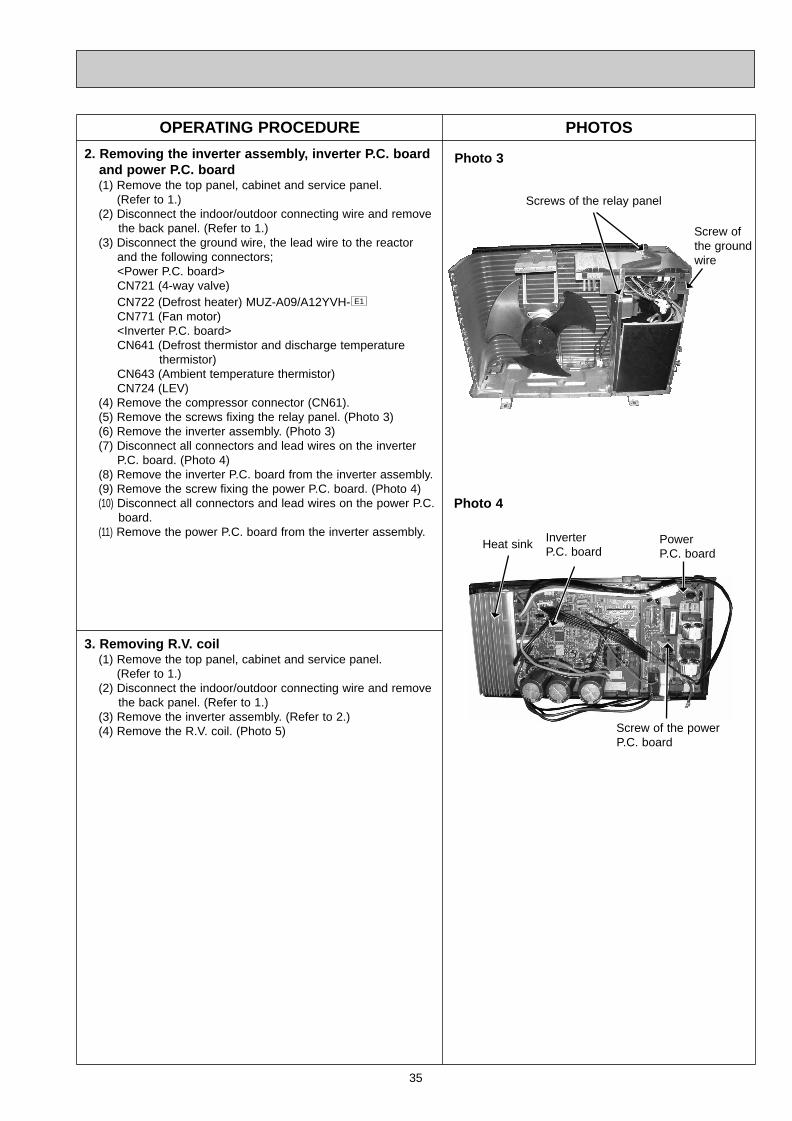
35
OPERATING PROCEDURE PHOTOS
2. Removing the inverter assembly, inverter P.C. boardand power P.C. board (1) Remove the top panel, cabinet and service panel.
(Refer to 1.)(2) Disconnect the indoor/outdoor connecting wire and remove
the back panel. (Refer to 1.)(3) Disconnect the ground wire, the lead wire to the reactor
and the following connectors;<Power P.C. board>CN721 (4-way valve)CN722 (Defrost heater) MUZ-A09/A12YVH-CN771 (Fan motor)<Inverter P.C. board>CN641 (Defrost thermistor and discharge temperature
thermistor)CN643 (Ambient temperature thermistor) CN724 (LEV)
(4) Remove the compressor connector (CN61).(5) Remove the screws fixing the relay panel. (Photo 3)(6) Remove the inverter assembly. (Photo 3)(7) Disconnect all connectors and lead wires on the inverter
P.C. board. (Photo 4)(8) Remove the inverter P.C. board from the inverter assembly.(9) Remove the screw fixing the power P.C. board. (Photo 4)(10) Disconnect all connectors and lead wires on the power P.C.
board.(11) Remove the power P.C. board from the inverter assembly.
E1
Photo 3
Photo 4
Screw of the powerP.C. board
Heat sink
3. Removing R.V. coil (1) Remove the top panel, cabinet and service panel.
(Refer to 1.)(2) Disconnect the indoor/outdoor connecting wire and remove
the back panel. (Refer to 1.)(3) Remove the inverter assembly. (Refer to 2.)(4) Remove the R.V. coil. (Photo 5)
Screws of the relay panel
InverterP.C. board
PowerP.C. board
Screw ofthe groundwire
OB328A --2qxp 04.4.26 4:50 PM Page 35
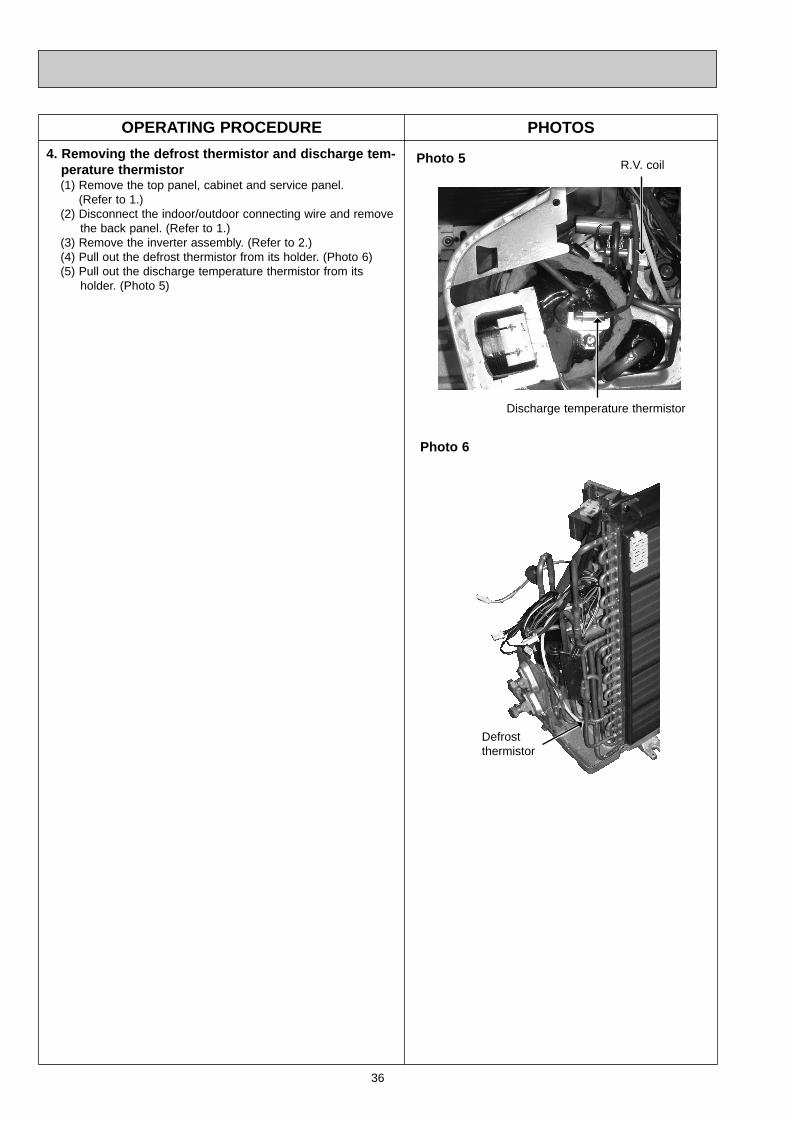
36
OPERATING PROCEDURE PHOTOS
4. Removing the defrost thermistor and discharge tem-perature thermistor(1) Remove the top panel, cabinet and service panel.
(Refer to 1.)(2) Disconnect the indoor/outdoor connecting wire and remove
the back panel. (Refer to 1.)(3) Remove the inverter assembly. (Refer to 2.)(4) Pull out the defrost thermistor from its holder. (Photo 6)(5) Pull out the discharge temperature thermistor from its
holder. (Photo 5)
Photo 5
Photo 6
Defrostthermistor
Discharge temperature thermistor
R.V. coil
OB328A --2qxp 04.4.26 4:50 PM Page 36
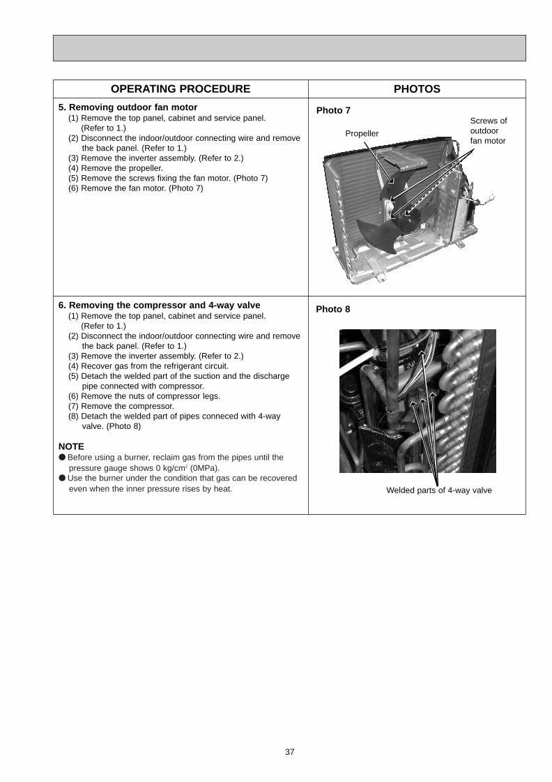
37
OPERATING PROCEDURE PHOTOS
5. Removing outdoor fan motor(1) Remove the top panel, cabinet and service panel.
(Refer to 1.)(2) Disconnect the indoor/outdoor connecting wire and remove
the back panel. (Refer to 1.)(3) Remove the inverter assembly. (Refer to 2.)(4) Remove the propeller.(5) Remove the screws fixing the fan motor. (Photo 7)(6) Remove the fan motor. (Photo 7)
Photo 7
Photo 8
Welded parts of 4-way valve
Propeller
Screws of outdoor fan motor
6. Removing the compressor and 4-way valve(1) Remove the top panel, cabinet and service panel.
(Refer to 1.)(2) Disconnect the indoor/outdoor connecting wire and remove
the back panel. (Refer to 1.)(3) Remove the inverter assembly. (Refer to 2.)(4) Recover gas from the refrigerant circuit.(5) Detach the welded part of the suction and the discharge
pipe connected with compressor.(6) Remove the nuts of compressor legs.(7) Remove the compressor.(8) Detach the welded part of pipes conneced with 4-way
valve. (Photo 8)
NOTE● Before using a burner, reclaim gas from the pipes until the
pressure gauge shows 0 kg/cm2 (0MPa).● Use the burner under the condition that gas can be recovered
even when the inner pressure rises by heat.
OB328A --2qxp 04.4.26 4:50 PM Page 37
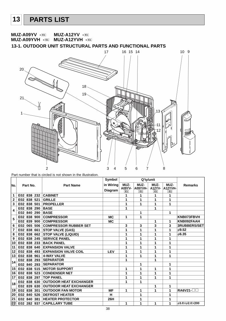
38
13 PARTS LIST
13-1. OUTDOOR UNIT STRUCTURAL PARTS AND FUNCTIONAL PARTS
1
11
12
2
1417
13
10 9
CABINETGRILLEPROPELLERBASEBASECOMPRESSORCOMPRESSORCOMPRESSOR RUBBER SETSTOP VALVE (GAS)STOP VALVE (LIQUID)SERVICE PANELBACK PANELEXPANSION VALVEEXPANSION VALVE COIL4-WAY VALVESEPARATORSEPARATORMOTOR SUPPORTCONDENSER NETTOP PANELOUTDOOR HEAT EXCHANGEROUTDOOR HEAT EXCHANGEROUTDOOR FAN MOTORDEFROST HEATERHEATER PROTECTORCAPILLARY TUBE
E02 838 232E02 838 521E02 838 501E02 838 290E02 840 290E02 838 900E02 839 900E02 065 506E02 838 661E02 838 662E02 838 245E02 838 233E02 838 640E02 838 493E02 838 961E02 838 293E02 840 293E02 838 515E02 838 523E02 838 297E02 838 630E02 839 630E02 838 301E02 840 526E02 840 381E02 282 937
123
4
5
678910111213
14
151617
18
19202122
KNB073FBVHKNB092FAAH3RUBBERS/SET{9.52{6.35
RA6V21-
{3.0✕{2.0✕200
MCMC
LEV
MFH
26H
1111
1
311111111
1111
1
1
111
11
31111111
11111
1111
1111
1311111111
111
11
1
111
1
131111111
1111
11111
Symbol
in Wiring
Diagram
Q'ty/unit
RemarksPart No.No. Part Name MUZ-A09YV-
E1
MUZ-A12YV-
E1
MUZ-A09YVH-
E1
MUZ-A12YVH-
E1
MUZ-A09YV - MUZ-A12YV -MUZ-A09YVH - MUZ-A12YVH - E1E1
E1E1
3 4 5 6 7 8
1516
20
18
19
Part number that is circled is not shown in the illustration.
21
OB328A --2qxp 04.4.26 4:50 PM Page 38
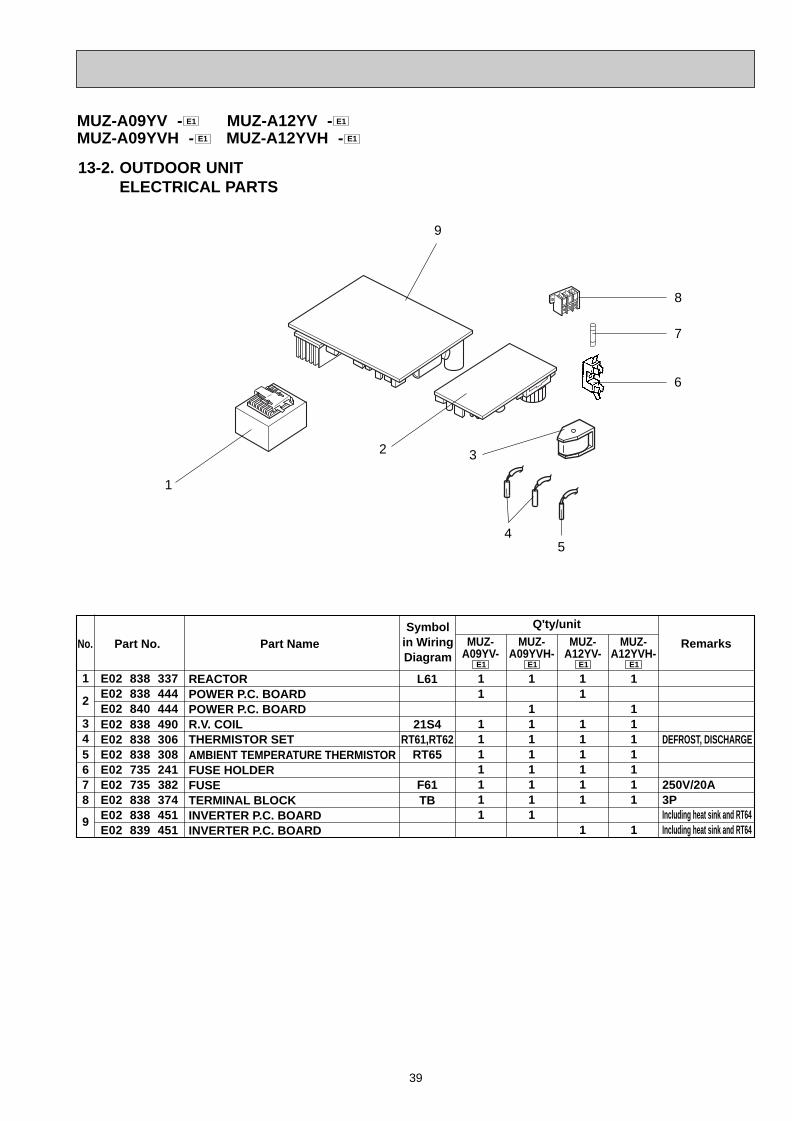
39
13-2. OUTDOOR UNIT ELECTRICAL PARTS
9
6
1
4
REACTORPOWER P.C. BOARDPOWER P.C. BOARDR.V. COILTHERMISTOR SETAMBIENT TEMPERATURE THERMISTORFUSE HOLDERFUSETERMINAL BLOCKINVERTER P.C. BOARDINVERTER P.C. BOARD
E02 838 337E02 838 444E02 840 444E02 838 490E02 838 306E02 838 308E02 735 241E02 735 382E02 838 374E02 838 451E02 839 451
1
2
345678
9
Symbolin WiringDiagram
Q'ty/unit
DEFROST, DISCHARGE
250V/20A3PIncluding heat sink and RT64Including heat sink and RT64
RemarksPart No.No. Part Name
L61
21S4RT61,RT62
RT65
F61TB
11
1111111
1
11111111
11
111111
1
1
1111111
1
MUZ-A09YV-
E1
MUZ-A09YVH-
E1
MUZ-A12YV-
E1
MUZ-A12YVH-
E1
MUZ-A09YV - MUZ-A12YV -MUZ-A09YVH - MUZ-A12YVH - E1E1
E1E1
2 3
5
7
8
OB328A --2qxp 04.4.26 4:50 PM Page 39
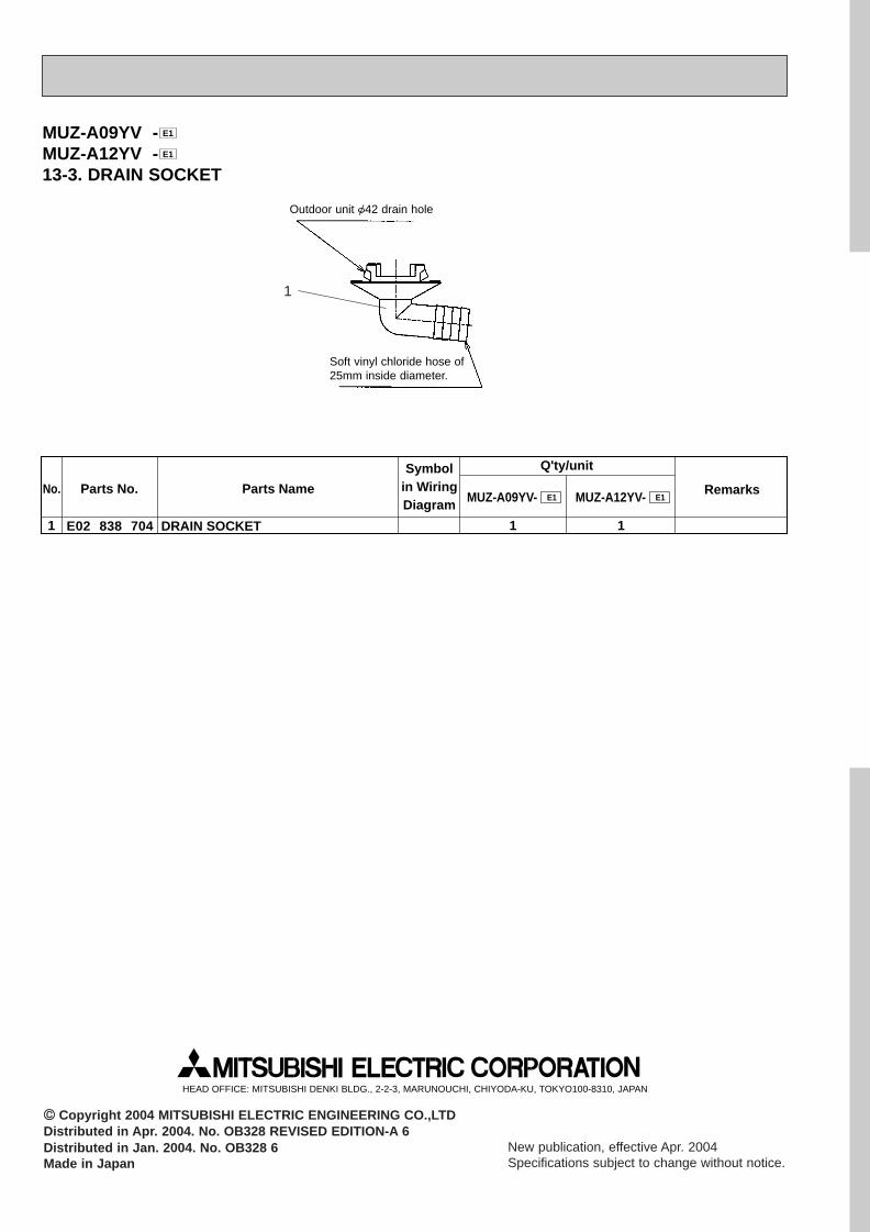
Outdoor unit {42 drain hole
Soft vinyl chloride hose of25mm inside diameter.
MUZ-A09YV -MUZ-A12YV -13-3. DRAIN SOCKET
E1
E1
Symbolin WiringDiagram
Q'ty/unit
MUZ-A09YV- RemarksParts No. Parts NameE1 MUZ-A12YV- E1
E02 838 7041 DRAIN SOCKET
No.
1 1
HEAD OFFICE: MITSUBISHI DENKI BLDG., 2-2-3, MARUNOUCHI, CHIYODA-KU, TOKYO100-8310, JAPAN
CC Copyright 2004 MITSUBISHI ELECTRIC ENGINEERING CO.,LTDDistributed in Apr. 2004. No. OB328 REVISED EDITION-A 6Distributed in Jan. 2004. No. OB328 6Made in Japan
New publication, effective Apr. 2004Specifications subject to change without notice.
1
OB328A --2qxp 04.4.26 4:50 PM Page 40


