
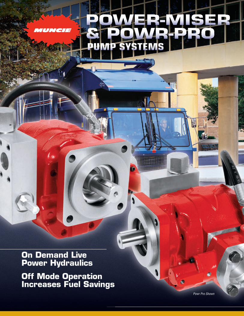
Powr Pro Shown
On Demand LivePower Hydraulics
Off Mode OperationIncreases Fuel Savings
pump systems

MP09-05 Printed in the U.S.A.© Muncie Power Products, Inc. 2009
Muncie Power Products, Inc. Member of the Interpump Hydraulics GroupGeneral Offices and Distribution Center • P.O. Box 548 • Muncie, IN 47308-0548
(765) 284-7721 • FAX (765) 284-6991 • E-mail [email protected] Web site http://www.munciepower.com
Drive Products, Exclusive Agents for Canada, ISO Certified by an Accredited Registrar
POwer-MISer & POwr-PrOmodel number construction
NOTES: Maximum oil temperature is 200°F (93°C). Never use Teflon Tape on pipe ports. 10 Micron Filtration Recommended.
PuMP Model PL14 (not available w/PPV) PL19 PL23 PL25 PM27 PM31 PM35 PM40
Shaft 01—1.0” Rd. (25.4 mm) (L Only) 05—1.25” 14T (31.8 mm) (M Only) 07—1.25” Rd. (31.8 mm) (L23 & M Only)
MountIng flange C—SAE “C” 4-BOLT L—SAE “C” 2-BOLT (M only)
Port tyPe F—SAE 4-BOLT
Port locatIon S—SIDE
bleed valve** A — No Bleed Valve B — 2 GPM (8 LPM) flow control valve* 00 — No Option VP-10 (Fixed) 28 — 28 GPM (106 LPM) 33 — 33 GPM (125 LPM) 36 — 36 GPM (136 LPM) 40 — 40 GPM (151 LPM) 52 — 52 GPM (197 LPM) 55 — 55 GPM (208 LPM) 63 — 63 GPM (238 LPM) VP-15 (Adjustable) 15 — 5 GPM (19 LPM) to 50 GPM (180 LPM)hoSe KIt A — No Hose Kit H — For PPV OnlyPowr-Pro(P) / Power-MISer(M) valve P — PPV-2402 — PM27, PM31, PL19, PL23, PL25 P — PPV-3202 — PM35, PM40 M — PMV-20 — PL14 M — PMV-24 — PM27, PM31, PL19, PL23, PL25 M — PMV-32 — PM35, PM40rotatIon L — Left Hand (CCW) R — Right Hand (CW)
pm40 – 07 c f s l – m – A – 63 – b
* OPTIONAL. Bypass flow should not exceed output flow by more than 50%. Contact Muncie Sales for the correct selection for your application.**POWER-MISER ONLy: A bleed valve must always be installed to prevent premature pump failure. Part Number FFC-3-2 (not used on PPV). NOTE: Vehicle must be equipped with an air system. POWR-PRO valve must be shifted with a 2-position, 4-way valve.
l series pump specificAtions
PL]14 3.18 (52) 3000 800 3000 (207) 20 (1.4) 1-1/2* 1 5In.Hg.(.17BAR)PL]19 4.46 (73) 3000 800 3000 (207) 20 (1.4) 1-1/2 1-1/4 5In.Hg.(.17BAR)PL]23 5.20 (85) 3000 800 2500 (172) 20 (1.4) 1-1/2 1-1/4 5In.Hg.(.17BAR)PL]25 5.73 (93) 2500 800 2500 (172) 20 (1.4) 1-1/2 1-1/4 5In.Hg.(.17BAR)
* Power-Miser Only: Pump Inlet Port is 1-1/4, but the Power-Miser Valve Block Inlet Port is 1-1/2.
Modelno.
dISPl.cu. In. (cc)
Max.rPM
MIn.rPM
Max.PSI (bar)
Max. offPSI (bar)
Inlet Port Sae 4-bolt
outlet Port Sae 4-bolt
Max InletvacuuM
*
**
m series pump specificAtions
PM]27 6.10 (100) 3000 800 3000 (207) 20 (1.4) 1-1/2 1-1/4 5In.Hg.(.17BAR)PM]31 7.11 (117) 3000 800 3000 (207) 20 (1.4) 1-1/2 1-1/4 5In.Hg.(.17BAR)PM]35 8.20 (134) 3000 800 2500 (172) 20 (1.4) 2 1-1/4 5In.Hg.(.17BAR)PM]40 9.27 (152) 2500 800 2500 (172) 20 (1.4) 2 1-1/4 5In.Hg.(.17BAR)
* Off-Mode RPM. 2500 RPM for On-Mode, except PL]25 and PM]40 which is 2300 RPM.
Modelno.
dISPl.cu. In. (cc)
Max.rPM
MIn.rPM
Max.PSI (bar)
Max. offPSI (bar)
Inlet Port Sae 4-bolt
outlet Port Sae 4-bolt
Max InletvacuuM
*
*
For Replacement Pump Only Pump Prefix is: PML1-]]] or PMM1-]]] (Delete model coding after Rotation)


