

Pedestrian Protection
Definitionof the Measuring Point
Assessment of 2D vs. 3D
Impactor Positioning Methods
12.05.2014
255th GRSP, 19 – 23 May 2014, Geneva
Preamble:
2D method refers to measuring point and center of gravity (CoG) of the impactor being in one vertical, longitudinal plane.3D method refers to the positioning of the headform based on a first contact with the bonnet top without any reference to the CoG.
Pedestrian ProtectionHead Impact – 2D / 3D Method
355th GRSP, 19 – 23 May 2014, Geneva
Introduction
Conditions to be discussed
Vehicle outer surfaces with ambiguities
Summary
Pedestrian ProtectionHead Impact – 2D / 3D Method

455th GRSP, 19 – 23 May 2014, Geneva
• Positioning of pedestrian protection impactors is currently under discussion
• The 2D head impact positioning method is the agreed procedure for type
approvals since pedestrian protection legislation became effective in Japan and
the EU in 2005
• A Regulation shall provide accountable framework of rules
• Room for interpretation shall be avoided
• Gtr No 9 language unintentionally provides room for (geometrical) interpretation
• Data has been requested to highlight potential issues with new interpretation of
impactor positioning method
• Information shown in following slides is not related to safety performance
Pedestrian ProtectionHead Impact – 2D / 3D Method
555th GRSP, 19 – 23 May 2014, Geneva
Introduction
Conditions to be discussed
Vehicle outer surfaces with ambiguities
Summary
Pedestrian ProtectionHead Impact – 2D / 3D Method

655th GRSP, 19 – 23 May 2014, Geneva
• Impactor main direction of action is along its center of gravity
• Using 3D first contact, vehicle surface variation affects the
impactor overall positioning; tolerances get higher influence
in the whole test procedure
• Concave surfaces (radius ≤ impactor radius) lead to multiple points
of contact where HIC cannot be assigned to one single point
• Areas where a test cannot be assigned
to one single point are considered
to be not testable
Pedestrian ProtectionHead Impact – 2D / 3D Method
For details please refer to document GRSP-49-31
755th GRSP, 19 – 23 May 2014, Geneva
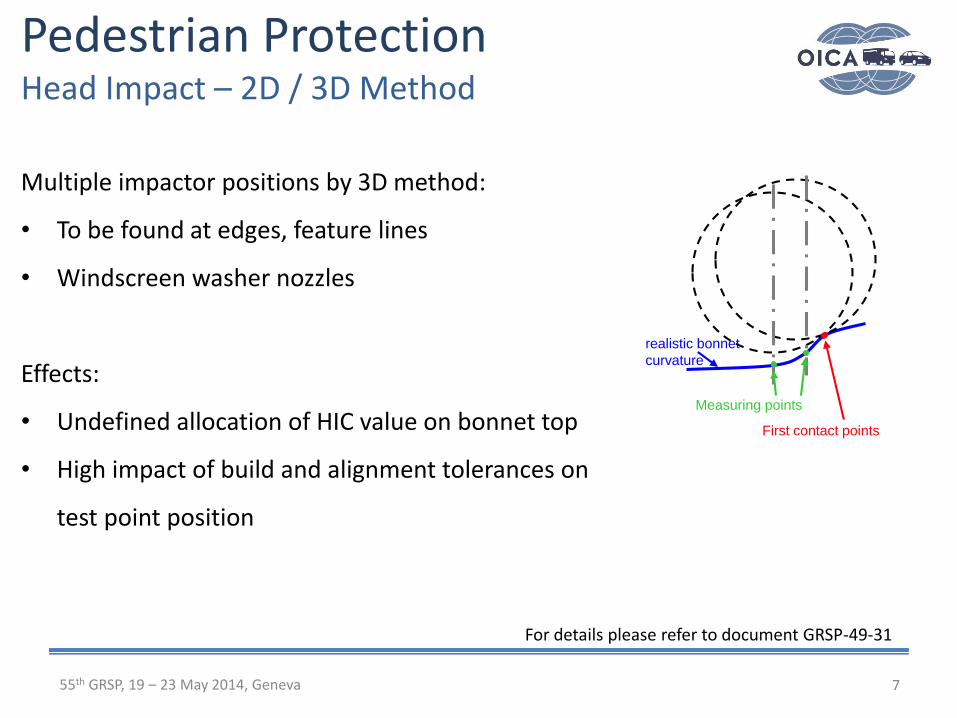
Multiple impactor positions by 3D method:
• To be found at edges, feature lines
• Windscreen washer nozzles
Effects:
• Undefined allocation of HIC value on bonnet top
• High impact of build and alignment tolerances on
test point position
Pedestrian ProtectionHead Impact – 2D / 3D Method
realistic bonnet
curvature
First contact points
Measuring points
For details please refer to document GRSP-49-31
55th GRSP, 19 – 23 May 2014, Geneva
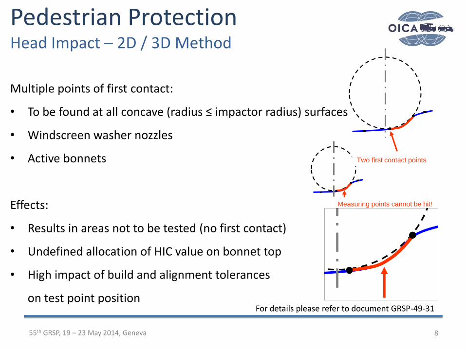
Multiple points of first contact:
• To be found at all concave (radius ≤ impactor radius) surfaces
• Windscreen washer nozzles
• Active bonnets
Effects:
• Results in areas not to be tested (no first contact)
• Undefined allocation of HIC value on bonnet top
• High impact of build and alignment tolerances
on test point position
Pedestrian ProtectionHead Impact – 2D / 3D Method
Measuring points cannot be hit!
Two first contact points
8
For details please refer to document GRSP-49-31

955th GRSP, 19 – 23 May 2014, Geneva
Introduction
Conditions to be discussed
Vehicle outer surfaces with ambiguities
Summary
Pedestrian ProtectionHead Impact – 2D / 3D Method
1055th GRSP, 19 – 23 May 2014, Geneva
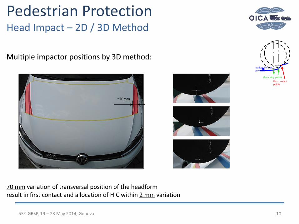
Multiple impactor positions by 3D method:
70 mm variation of transversal position of the headformresult in first contact and allocation of HIC within 2 mm variation
Pedestrian ProtectionHead Impact – 2D / 3D Method
realistic bonnet
curvature
First contact
points
Measuring points
~70mm
1155th GRSP, 19 – 23 May 2014, Geneva
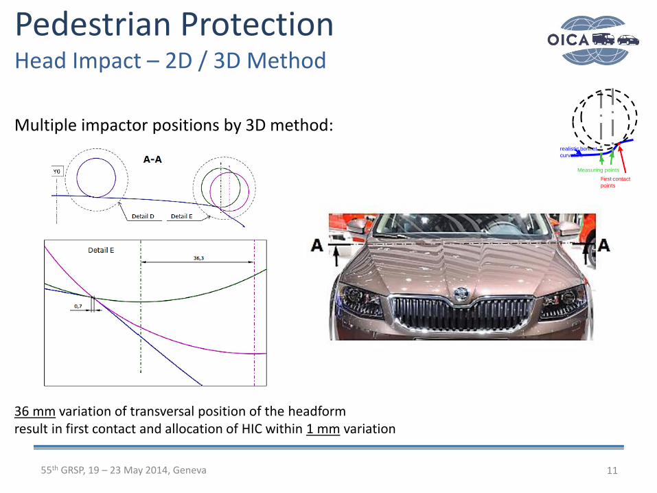
Multiple impactor positions by 3D method:
36 mm variation of transversal position of the headformresult in first contact and allocation of HIC within 1 mm variation
Pedestrian ProtectionHead Impact – 2D / 3D Method
realistic bonnet
curvature
First contact
points
Measuring points
1255th GRSP, 19 – 23 May 2014, Geneva
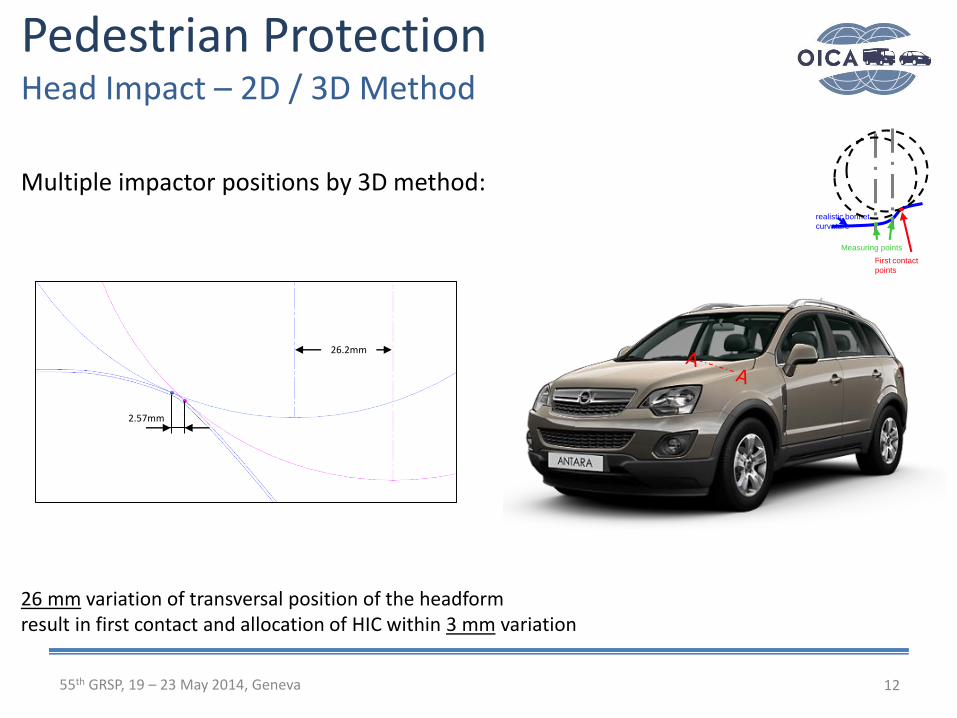
Multiple impactor positions by 3D method:
26 mm variation of transversal position of the headformresult in first contact and allocation of HIC within 3 mm variation
Pedestrian ProtectionHead Impact – 2D / 3D Method
2.57mm
26.2mm
realistic bonnet
curvature
First contact
points
Measuring points
1355th GRSP, 19 – 23 May 2014, Geneva
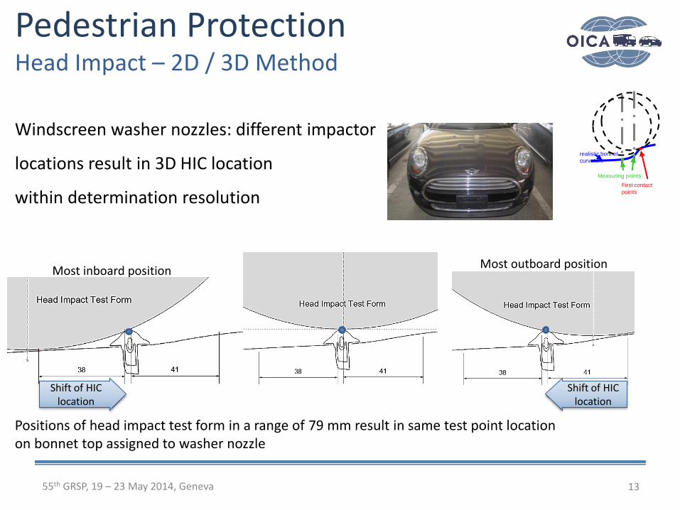
Windscreen washer nozzles: different impactor
locations result in 3D HIC location
within determination resolution
Positions of head impact test form in a range of 79 mm result in same test point location on bonnet top assigned to washer nozzle
Pedestrian ProtectionHead Impact – 2D / 3D Method
realistic bonnet
curvature
First contact
points
Measuring points
Most outboard positionMost inboard position
Shift of HIC location
Shift of HIC location

31mm 36 mm
1455th GRSP, 19 – 23 May 2014, Geneva
Windscreen washer nozzles: different impactor locations
result in 3D HIC location within determination resolution
85 mm variation of transversal position of the headformresult in first contact and allocation of HIC on the washer nozzle (8 mm variation)
Pedestrian ProtectionHead Impact – 2D / 3D Method
realistic bonnet
curvature
First contact
points
Measuring points
1555th GRSP, 19 – 23 May 2014, Geneva
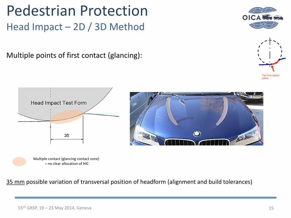
Multiple points of first contact (glancing):
35 mm possible variation of transversal position of headform (alignment and build tolerances)
Pedestrian ProtectionHead Impact – 2D / 3D Method
Two first contact
points
Multiple contact (glancing contact zone)– no clear allocation of HIC
1655th GRSP, 19 – 23 May 2014, Geneva
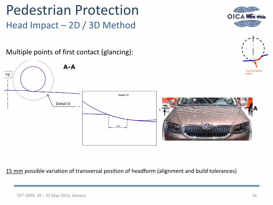
Pedestrian ProtectionHead Impact – 2D / 3D Method
Two first contact
points
Multiple points of first contact (glancing):
15 mm possible variation of transversal position of headform (alignment and build tolerances)
1755th GRSP, 19 – 23 May 2014, Geneva
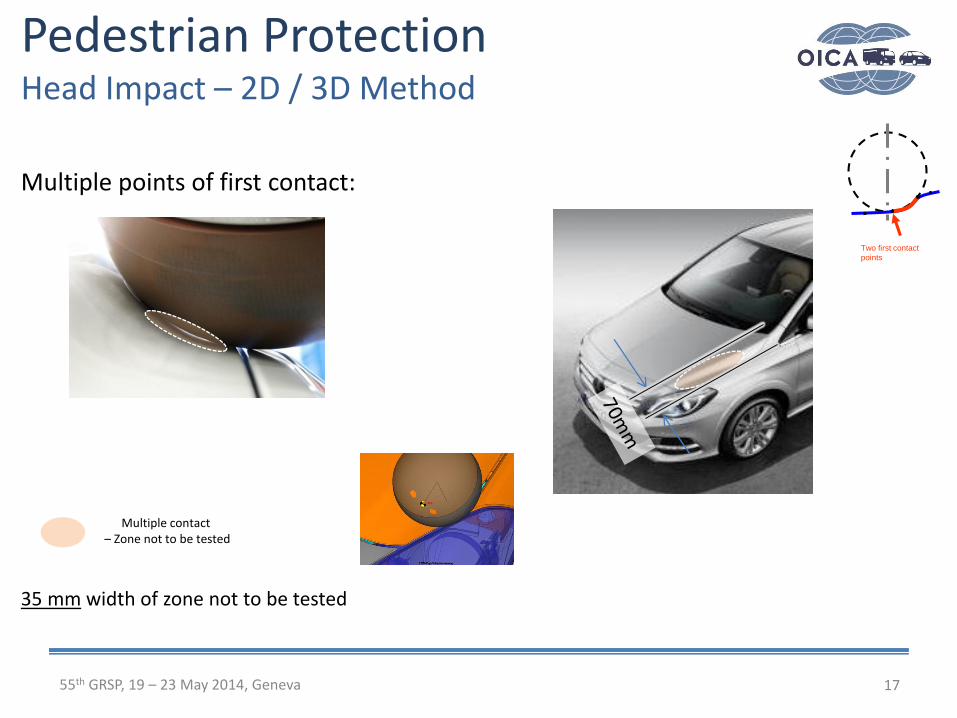
Multiple points of first contact:
35 mm width of zone not to be tested
Pedestrian ProtectionHead Impact – 2D / 3D Method
Two first contact
points
Multiple contact – Zone not to be tested

1855th GRSP, 19 – 23 May 2014, Geneva
Multiple points of first contact:
30 mm width of zone not to be tested
Pedestrian ProtectionHead Impact – 2D / 3D Method
Two first contact
points
Multiple contact – Zone not to be tested

1955th GRSP, 19 – 23 May 2014, Geneva
Multiple points of first contact:
45 mm width of zone not to be tested
Pedestrian ProtectionHead Impact – 2D / 3D Method
Two first contact
points
2055th GRSP, 19 – 23 May 2014, Geneva
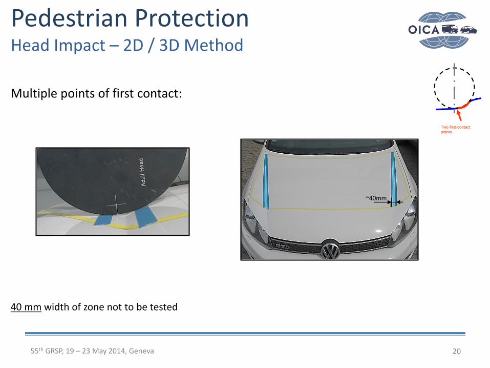
Multiple points of first contact:
40 mm width of zone not to be tested
Pedestrian ProtectionHead Impact – 2D / 3D Method
Two first contact
points
~40mm

2155th GRSP, 19 – 23 May 2014, Geneva
Multiple points of first contact:
35 mm width of zone not to be tested
Pedestrian ProtectionHead Impact – 2D / 3D Method
Two first contact
points
35mm
Not to be tested between white lines
2255th GRSP, 19 – 23 May 2014, Geneva
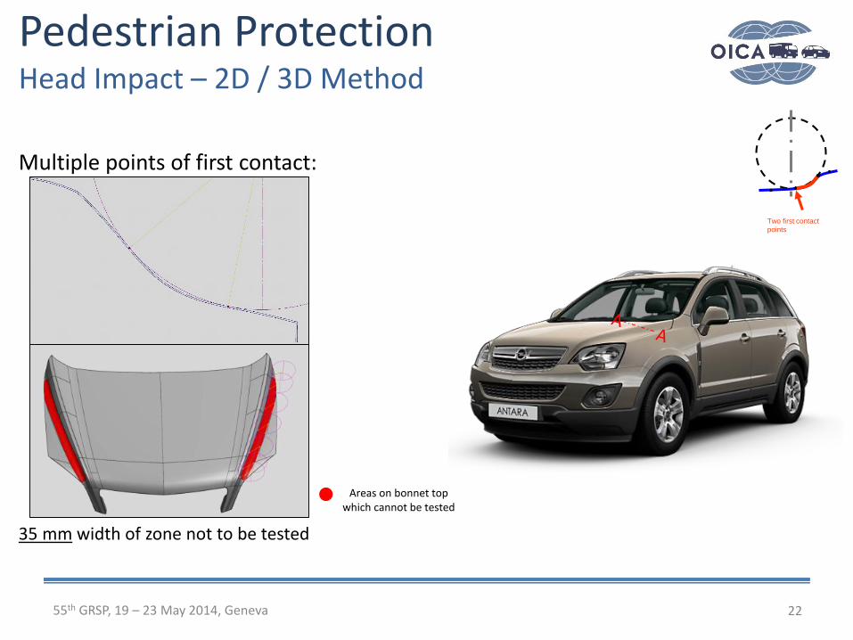
Multiple points of first contact:
35 mm width of zone not to be tested
Pedestrian ProtectionHead Impact – 2D / 3D Method
Two first contact
points
Areas on bonnet top which cannot be tested
2355th GRSP, 19 – 23 May 2014, Geneva
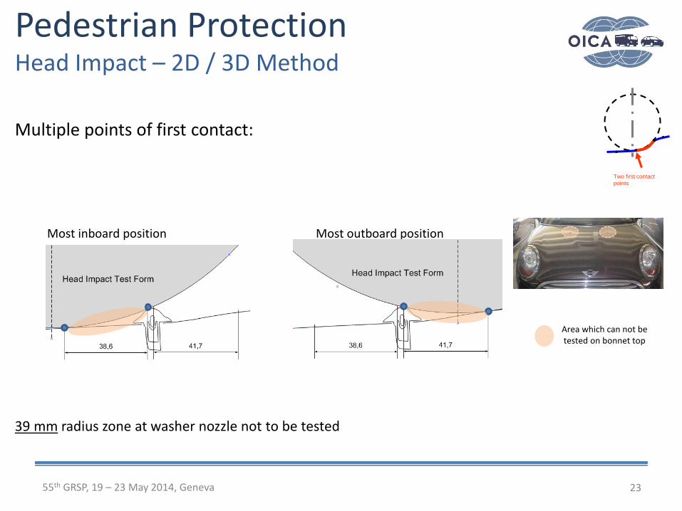
Multiple points of first contact:
39 mm radius zone at washer nozzle not to be tested
Pedestrian ProtectionHead Impact – 2D / 3D Method
Two first contact
points
Most outboard positionMost inboard position
Area which can not be tested on bonnet top

2455th GRSP, 19 – 23 May 2014, Geneva
Multiple points of first contact:
Pedestrian ProtectionHead Impact – 2D / 3D Method
Two first contact
points
2555th GRSP, 19 – 23 May 2014, Geneva
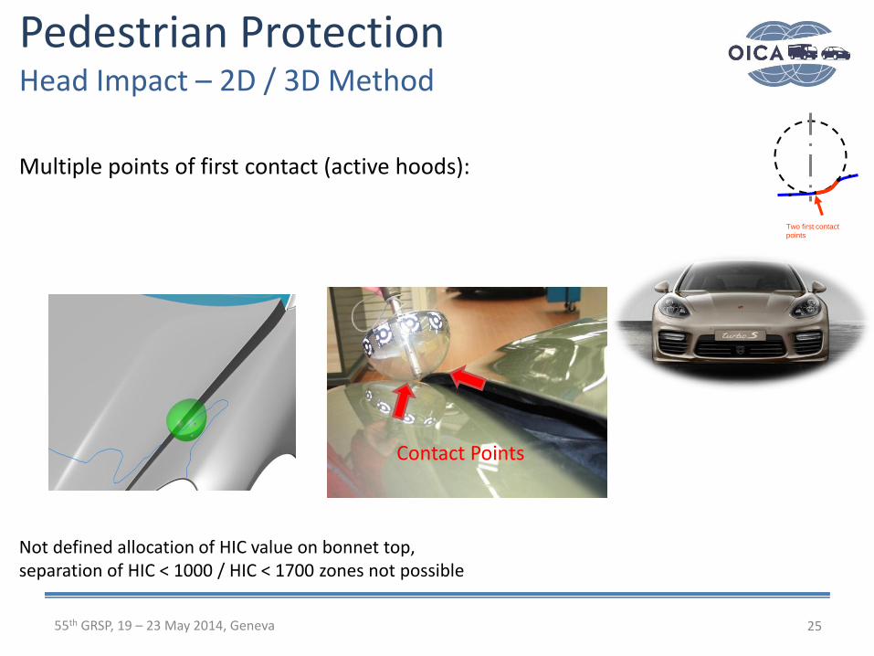
Multiple points of first contact (active hoods):
Not defined allocation of HIC value on bonnet top,separation of HIC < 1000 / HIC < 1700 zones not possible
Pedestrian ProtectionHead Impact – 2D / 3D Method
Two first contact
points
Contact Points

2655th GRSP, 19 – 23 May 2014, Geneva
Pedestrian ProtectionHead Impact – 2D / 3D Method
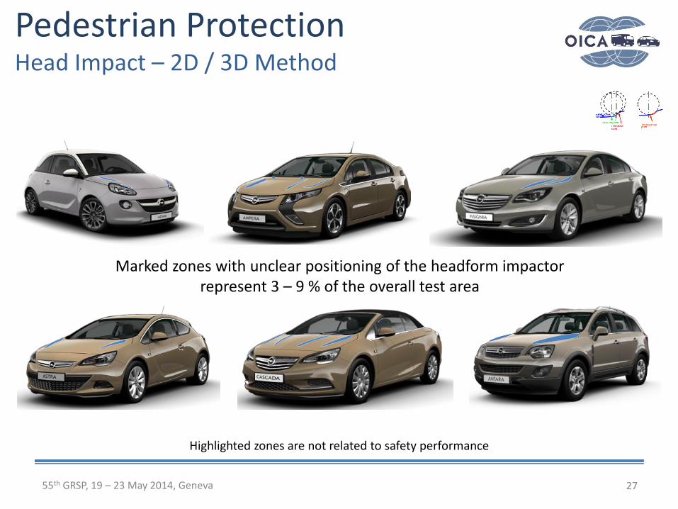
Highlighted zones are not related to safety performance
Marked zones with unclear positioning of the headform impactorrepresent 3 – 9 % of the overall test area
2755th GRSP, 19 – 23 May 2014, Geneva
Pedestrian ProtectionHead Impact – 2D / 3D Method
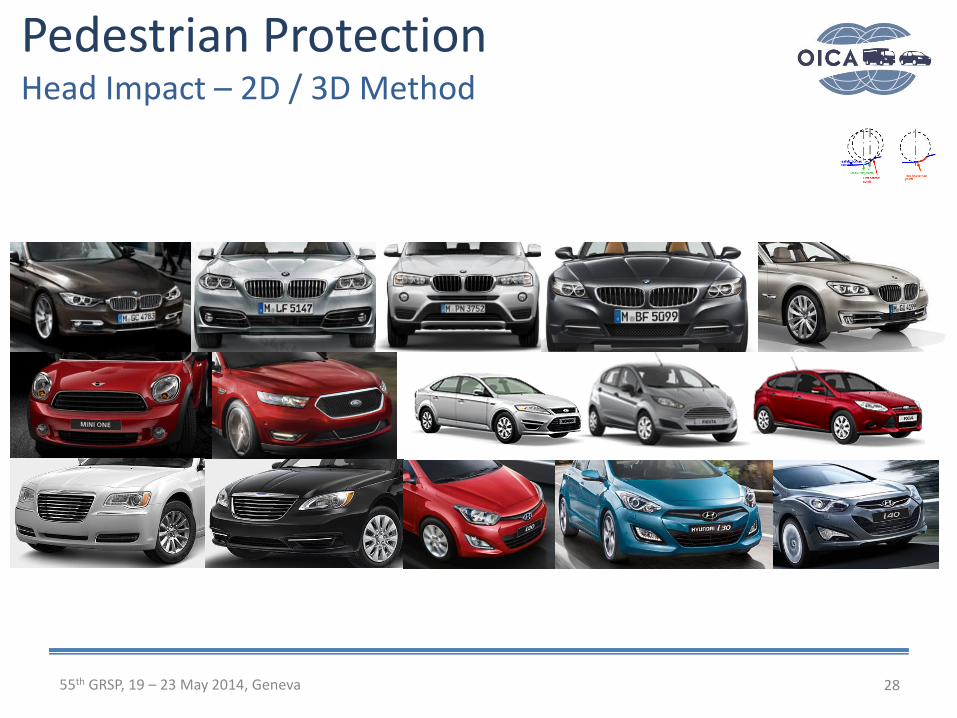
Highlighted zones are not related to safety performance
Marked zones with unclear positioning of the headform impactorrepresent 3 – 9 % of the overall test area
2855th GRSP, 19 – 23 May 2014, Geneva
Pedestrian ProtectionHead Impact – 2D / 3D Method

55th GRSP, May 2014, Geneva 29
Pedestrian ProtectionHead Impact – 2D / 3D Method
Some of the photographs are taken from the internet; none of the photographs is related to safety performance!

3055th GRSP, 19 – 23 May 2014, Geneva
Introduction
Conditions to be discussed
Vehicle outer surfaces with ambiguities
Summary
Pedestrian ProtectionHead Impact – 2D / 3D Method

Pedestrian ProtectionHead Impact – 2D / 3D Method
3155th GRSP, 19 – 23 May 2014, Geneva
• 2D head impact positioning method is the agreed procedure for type approval
since 2005 when pedestrian protection legislation became effective in Japan
and the EU
• Numerous vehicles exist where the 3D method interpretation of gtr No. 9
creates issues for the determination of the test zone or the test execution
• Resulting from the 3D method, 3 – 9 % of headform test areas cannot to be
tested
• Possible side effects described in this presentation and creating issues for
testing do not exist when the 2D method as agreed for UNECE R127* is used
• As pointed out, each point within the test area described in gtr No. 9 CAN be
tested and a single HIC value CAN be assigned
• The same logic applies to proposed amendments to the legform test
* see document: ECE/TRANS/WP.29/2014/37

Ph
oto
gra
ph
: B
GS
Bo
eh
me &
Ge
hrin
g
Measuring
pointHard structure etc.
to be assessed
Pedestrian ProtectionProposed Amendment
3255th GRSP, 19 – 23 May 2014, Geneva
Extract from GRSP-54-07-Rev.1

33
Thank You!
On behalf of OICA provided by:
Franz Roth, AudiWinfried Schmitt, BMWKlaus Rathje, DaimlerBenjamin Buenger, OpelThomas Kinsky, OpelJörg Kusche, PorscheOlaf Insel, Volkswagen
55th GRSP, 19 – 23 May 2014, Geneva
Pedestrian ProtectionHead Impact – 2D / 3D method


