
IDX-OM-J034 Initial issue: Mar, 2006
Rev.G: Feb, 2017
PRODUCT NAME
Refrigerated Air Dryer
MODEL / Series
IDF22E-20(-A,C,K,L,M,R,T) IDF22E-30(-A,C,K,L,M,R,T) IDF37E-20(-A,C,K,L,M,R,T) IDF37E-30(-A,C,K,L,M,R,T)
IDF55E-30(-A,C,L,M,R,T) IDF75E-30(-A,C,L,M,R,T)
Please read this manual prior of using the air dryer. Keep the manual readily available for
reference.
© 2017 SMC CORPORATION All Rights Reserved.

To Customers
Thanks for purchasing SMC Refrigerated Air Dryer.
This opertion manual must be read and understood throughoutly before handling. It provides all essential
information for maximizing product operating efficiency, as well as, for safe and longer life span operation.
For safety operation of SMC Refrigerated Air Dryer, read thoroughly and follow stated safety instructions, as well
as regulation stated within ISO 4414*1
& JIS B 8370*2
.
*1) ISO 4414: Pneumatic fluid power – Recommendations for the application of equipment to transmission
and control systems.
*2) JIS B 8370: Pneumatic fluid power – General rules relating to systems
This manual explains about installation and operation of the product. Only those who have thorough
understanding of the fundamental operating procedure or have basic knowledge and skills of handling industrial
product for the installation and operation of the product are qualified to perform installation and operation.
The contents of the operation manual and the other documents attached to the product cannot become a part of
the contract clause or cannot change and modify existing agreements, promises, and relationship.
Any statements contained in the operation manual cannot be newly guaranteed and modify existing guarantee
certificate.
You are not allowed to copy any part of this operation manual for usage of third person without informing it to us
beforehand.
Caution: Please understand that the contents of this operation manual are subject to
changed without previous notice.

Air Dryer Table of Contents
Table of Contents - 1
Chapter i Safety Instructions
i - 1 Warning: Before Using Air Dryer ............................................................................ i - 1
i - 1 - 1 Meanings of signs: Caution, Warning, Danger ............................................................ i - 1
i - 2 Danger Classifications / Position of Danger warning label ............................. i - 3
i - 2 - 1 Danger Classifications ................................................................................................ i - 3
i - 2 - 2 Danger of Electricity .................................................................................................... i - 4
i - 2 - 3 Danger of High Heat ................................................................................................... i - 4
i - 2 - 4 Danger of Rotor .......................................................................................................... i - 4
i - 2 - 5 Danger of Compressed Air Circuit ............................................................................. i - 4
i - 2 - 6 Positions of Danger Warning Label ............................................................................ i - 5
i - 2 - 7 Danger of Refrigerant ................................................................................................. i - 6
i - 2 - 8 Cautions about Usage ................................................................................................ i - 7
i - 2 - 9 Other Label ................................................................................................................. i - 7
i - 3 Disposal......................................................................................................................... i - 8
i - 4 Limited warranty and Disclaimer / Compliance Requirements ....................... i - 9
Chapter 1 Parts Name and Functions
1 - 1 Parts Names and Functions .................................................................................... 1 - 1
Chapter 2 Transportation / Installation
2 - 1 Transportation ............................................................................................................ 2 - 1
2 - 2 Installation ................................................................................................................... 2 - 2
2 - 2 - 1 Location ..................................................................................................................... 2 - 2
2 - 2 - 2 Anchorage ................................................................................................................. 2 - 2
2 - 2 - 3 Air piping .................................................................................................................... 2 - 3
2 - 2 - 4 Drain Tube ................................................................................................................. 2 - 3
2 - 2 - 5 Electric wiring ............................................................................................................ 2 - 4
2 - 3 Cautions about Reinstallation ................................................................................ 2 - 5
Chapter 3 Operation / Shutdown
3 - 1 Check points before operation ............................................................................... 3 - 1
3 - 2 Operation ..................................................................................................................... 3 - 1
3 - 3 Shutdown ..................................................................................................................... 3 - 2
3 - 4 Cautions about restart .............................................................................................. 3 - 2
3 - 5 Check points before restart ..................................................................................... 3 - 2
3 - 6 Precautions for long-term non-operation ...................................................... 3 - 2
Chapter 4 Maintenance
4 - 1 Daily inspection .......................................................................................................... 4 - 1
4 - 2 Periodical Maintenance ............................................................................................ 4 - 1
4 - 2 - 1 Cleaning of ventilation grille (suction grille) ....................................................................... 4 - 1
4 - 2 - 2 Service parts ..................................................................................................................... 4 - 1
4 - 2 - 3 Cleaning of the case assembly ......................................................................................... 4 - 1
Chapter 5 Troubleshooting ............................................................................................................... 5 - 1
5 - 1 Cause and countermeasure of errors .................................................................. 5 - 1
5 - 2 How to reset the thermal relay and high pressure switch .............................. 5 - 3
Table of Contents

Air Dryer Table of Contents
Table of Contents - 2
Chapter 6 References
6 - 1 Specifications ............................................................................................................. 6 - 1
6 - 2 Refrigerant with GWP reference ............................................................................ 6 - 1
6 - 3 Dimensions.................................................................................................................. 6 - 2
6 - 4 Electrical Circuit ......................................................................................................... 6 - 3
6 - 5 Compressed Air and Refrigerant Circuit / Operation Principles ................... 6 - 4
Chapter 7 Specification for Option A
7 - 1 Safety instructions ........................................................................................... 7 - 1
7 - 2 Specifications ................................................................................................... 7 - 1
7 - 3 Air piping ........................................................................................................... 7 - 1
7 - 4 Air flow capacity ............................................................................................... 7 - 1
7 - 5 Compressed Air and Refrigerant Circuit / Operation Principles ................. 7 - 2
Chapter 8 Specification for Option C
8 - 1 Safety instructions ........................................................................................... 8 - 1
8 - 2 Specifications ................................................................................................... 8 - 1
8 - 3 Precautions for the installation and handling of the product ...................... 8 - 1
Chapter 9 Specification for Option K
9 - 1 Safety instructions ........................................................................................... 9 - 1
9 - 2 Specifications ................................................................................................... 9 - 1
Chapter 10 Specification for Option L
10 - 1 Safety instructions ......................................................................................... 10 - 1
10 - 2 Specification ................................................................................................... 10 - 1
10 - 3 Maintenance .................................................................................................... 10 - 2
Chapter 11 Specification for Option M
11 - 1 Safety instructions ..........................................................................................11 - 1
11 - 2 Specifications ..................................................................................................11 - 2
11 - 3 Cautions for handling the motor type auto drain .........................................11 - 2
11 - 4 Electric circuit ..................................................................................................11 - 2
Chapter 12 Specification for Option R
12 - 1 Safety instructions ......................................................................................... 12 - 1
12 - 2 Specifications ................................................................................................. 12 - 1
12 - 3 Power supply connection procedure ........................................................... 12 - 2
12 - 4 Cautions for handling the GFCI .................................................................... 12 - 3
12 - 5 Electric circuit ................................................................................................. 12 - 3
Chapter 13 Specification for Option T
13 - 1 Safety instructions ......................................................................................... 13 - 1
13 - 2 Specifications ................................................................................................. 13 - 1
13 - 3 Remote operation ........................................................................................... 13 - 1
13 - 4 How to connect the power supply and signal cable ................................... 13 - 2
13 - 5 How to re-start the operation ........................................................................ 13 - 2
13 - 6 Electric circuit ................................................................................................. 13 - 3
Chapter 14 Service Record
14 - 1 Service Record ............................................................................................... 14 - 1
IDX-OM-J034 Air Dryer i Safety Instructions
i-1 Warning: Before Using Air Dryer i - 1
IDF Series
Safety Instructions
Before use, read and comprehend important cautionary
notification well on this operattion manual.
i-1 Warning: Before Using Air Dryer
In this chapter, the stated contents are especially about safety way to use the product. for customer.
An Air Dryer is installed on the downstream of the air compressor to remove moisture. We, manufacturer,
cannot take any responsibility if you use it for any other purpose.
An Air Dryer works with high voltage and has some parts that gets hot or rotates during operation. Ask vendor
if you need component replacement and servicing.
Not only people handle the air dryer but every people who perform maintenance on or do works related to it
should read safety instructions on this operation manual before ha ndling.
This operation manual is not a general safety manual which is practiced by safety training representatives.
People who handle this product or work around it need to take training to comprehand inherent risks of it and
master measures for safety.
It is usually responsible for super visor to follow the safety instructions, but each operator or maintemance
representative should do daily operations on their own head.
Operators and maintemance representatives should take the safety of working place and work environment
into account.
It is necessary to think of the safety of working place and work environment for each task
Take enough safety training before the operation training. It is very dangerous to do operation training without
any safety training. Operation training must be paid attention to its safety.
Reset the protective circuit referring to “5-2 How to reset the thermal relay and high pressure switch”.
i – 1 – 1 Meaning of Signs: Caution, Warning, Danger
These safety instructions are intended to prevent hazardous situation and/or product damage.
These instructions indicate the level of potential hazard by signs “Caution”, “Warning” or
“Danger”. Contents with these signs state about important instructions concerning safety.
Confirm where those signs are, and read and comprehend notices and cautionary notices well
before handling.
“Caution”, “Warning” or “Danger” is the order of importance (Danger>Warning>Caution).
Followings are the meanings of those signs.
Danger
Statements with the “Danger” sign explain about conditions in which there is a
possible result of serious injury or loss of life if someone handles wrongly during
operation or maintenance and did not follow the procedure to avoid danger.
i
IDX-OM-J034 Air Dryer i Safety Instructions
i-1 Warning: Before Using Air Dryer i - 2
IDF Series
Warning
Statements with the “Danger” sign explain about possibilities that can result in
serious injury or loss of life if someone handle wrongly during operation or
maintenance and did not follow the procedure to avoid danger.
Caution
Statements with the “Danger” sign explain about possibilities that can result in injury
or product damage if someone handles wrongly during operation or maintenance and
did not follow the procedure to avoid danger.

IDX-OM-J034 Air Dryer i Safety Instructions
i-2 Danger Classifications / Position of Danger Warning Label i - 3
IDF Series
i-2 Danger Classifications / Position of Danger Warning Label
To protect operator’s sefety, we group danger into some types uniquely and attached labels indicating those types.
Comfirm the contents of the danger types and positions of the labels before operation.
Warning
No one but professionals should operate an air dryer.
Transportation, installation, and maintenance involve risks. These should be done by
someone who have enough knowledge and experience about this product and incidental
devices.
No one but our service personnel or qualified person should open the cover panel of this
product.
Warning
Should any problem occur, address it according to statements on this manual.
Identify problems according to “Chapter 5 Troubleshooting.”
Ask repair and maintenance.
Warning
The product should not be operated in the event of any problems.
When the product gets out of order, shutdown it immediatery, and contact our service
person or qualified person.
i – 2 – 1 Danger Classifications
Specific danger classification of this product is as follows.
Danger of Electricity
Since this product runs at hign voltage, there is the danger of electric shock. So, we display
a symbol with indications, “Caution”, “Warning” or “Danger,” on the product and this
manual.
Danger of Heat
Since this product becomes hot while driving, there is the danger of burn injury. So, we
display a symbol with indications, “Caution”, “Warning” or “Danger,” on the product
and this manual.
Danger of Rotor
Since this product has parts that rotate while driving, there is the danger of catching your
fingers in or injury. So, we display a symbol with indications, “Caution”, “Warning” or
“Danger,” on the product and this manual.

IDX-OM-J034 Air Dryer i Safety Instructions
i-2 Danger Classifications / Position of Danger Warning Label i - 4
IDF Series
i – 2 – 2 Danger of Electricity Inside of this product, there is power-supplying section with high voltage separated by the
cover panel. Do not operate the product without the cover panel.
No one but trained qualified person should operate or inspect in the power transmission
sections.
Warning
Read with caution and pay attention to the notations on danger warning labels.
Do not remove or rub danger warning labels.
Confirm the positions of danger warning labels.
i – 2 – 3 Danger of High Heat
Warning
Since this product has parts that become hot during operation, there is the danger of burn
injury resulting from contact with them. What is more, there is also the danger of burn injury due to
remaining heat after the power supply is cut. Therefore, wait until the temperature of hot parts become
50oC and below.
i – 2 – 4 Danger of Rotor
Warning
Since this product has parts that rotate during operation, there is the danger of burn injury
resulting from contact with them. Though sometimes those parts can temporarily stop the rotation,
they will rotate again, and so do not work with them while driving.
i – 2 – 5 Danger of Compressed Air Circuit
Warning
Before replacing or cleaning parts, be sure to bleed compressed air remain inside of the
product untill the gauge indicates “0”. If you do not do this air-bleeding, there would be the
great danger of unexpected accident, such as shooting out of parts when they are being unscrewed.
IDX-OM-J034 Air Dryer i Safety Instructions
i-2 Danger Classifications / Position of Danger Warning Label i - 5
IDF Series
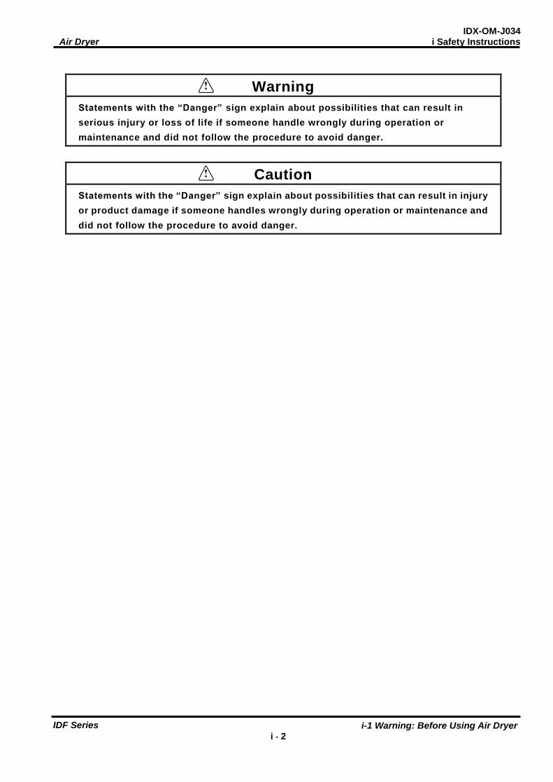
i – 2 – 6 Positions of Danger Warning Label
Warning
Read with caution and pay attention to the notations of danger warning labels.
Do not remove or rub danger warning labels.
Confirm the positions of danger warning labels.
Front
WARNING 警告!
1 Remove panels for maintenance only.
2 Never insert anything into product to ensure
safety.
3 Cut power prior to maintenance to prevent
electric shock.
4 Settle product to room temp.before main-
tenance toprevent burn or frostbite.
5 Ensure zero air pressure before replacing parts.
1 点検以外はパネルを取り外さないこと。
2 回転物があるので指、棒状の物を差し
込まないこと。
3 感電の恐れがあるので、点検の前には電源を
切ること。
4 火傷の恐れがあるので、点検の前には装置を
常温にすること。
5 部品交換の前には必ず、空気圧力を"0"に
すること。
!
IDX-OM-J034 Air Dryer i Safety Instructions
i-2 Danger Classifications / Position of Danger Warning Label i - 6
IDF Series
Front
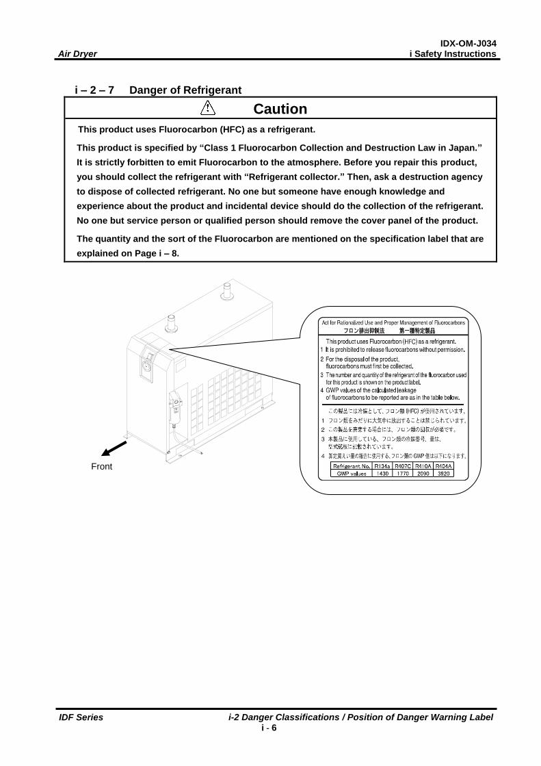
i – 2 – 7 Danger of Refrigerant
Caution
This product uses Fluorocarbon (HFC) as a refrigerant.
This product is specified by “Class 1 Fluorocarbon Collection and Destruction Law in Japan.”
It is strictly forbitten to emit Fluorocarbon to the atmosphere. Before you repair this product,
you should collect the refrigerant with “Refrigerant collector.” Then, ask a destruction agency
to dispose of collected refrigerant. No one but someone have enough knowledge and
experience about the product and incidental device should do the collection of the refrigerant.
No one but service person or qualified person should remove the cover panel of the product.
The quantity and the sort of the Fluorocarbon are mentioned on the specification label that are
explained on Page i – 8.
IDX-OM-J034 Air Dryer i Safety Instructions
i-2 Danger Classifications / Position of Danger Warning Label i - 7
IDF Series
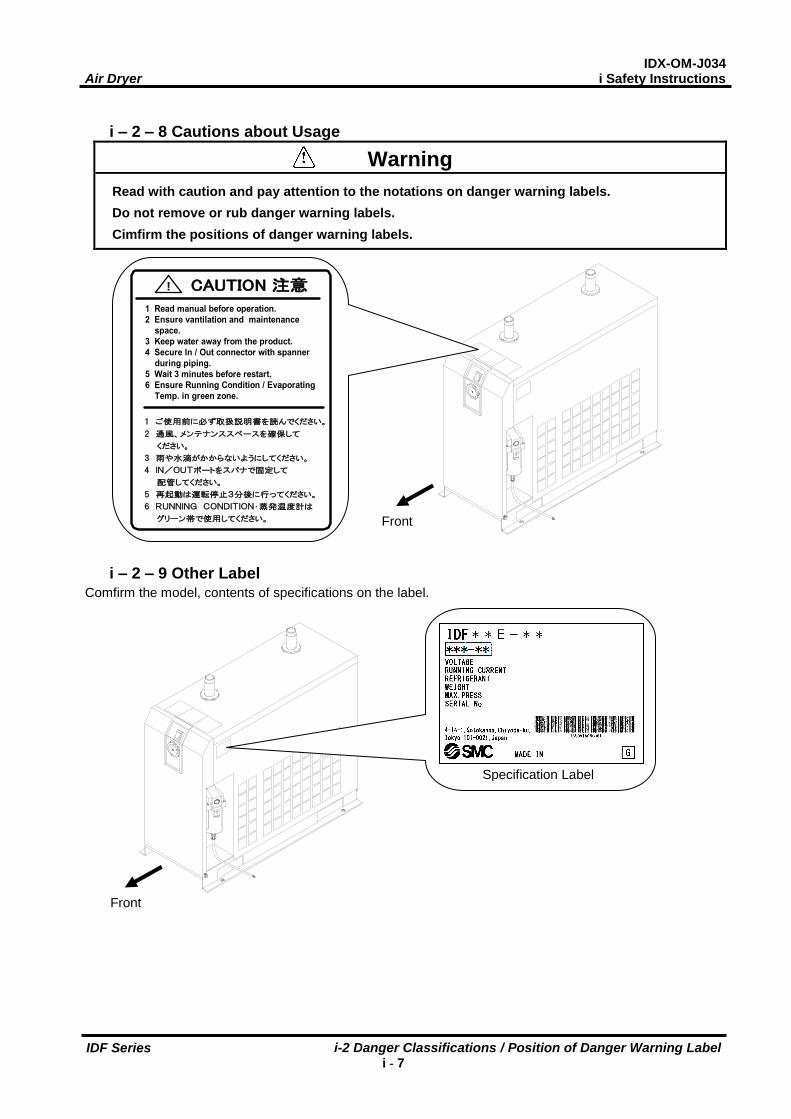
i – 2 – 8 Cautions about Usage
Warning
Read with caution and pay attention to the notations on danger warning labels.
Do not remove or rub danger warning labels.
Cimfirm the positions of danger warning labels.
i – 2 – 9 Other Label Comfirm the model, contents of specifications on the label.
Front
Specification Label
Front
CAUTION 注意!
1 Read manual before operation.
2 Ensure vantilation and maintenance
space.
3 Keep water away from the product.
4 Secure In / Out connector with spanner
during piping.
5 Wait 3 minutes before restart.
6 Ensure Running Condition / Evaporating
Temp. in green zone.
1 ご使用前に必ず取扱説明書を読んでください。
2 通風、メンテナンススペースを確保して
ください。
3 雨や水滴がかからないようにしてください。
4 IN/OUTポートをスパナで固定して
配管してください。
5 再起動は運転停止3分後に行ってください。
6 RUNNING CONDITION・蒸発温度計は
グリーン帯で使用してください。

IDX-OM-J034 Air Dryer i Safety Instructions
i-3 Disposal i – 8
IDF Series
i-3 Disposal
When you dispose of the product, you shoud collect the refrigerant and the refrigerat oil enclosed in the
refrigerant circuit.
Caurion
A sort of Fluorocarbon (HFC) is used for this product as refrigerant.
This product is specified by “Class1 Fluorocarbon Collection Destruction Law in Japan.”
It is strictly forbitten by the law to emit the refrigerant to the atmosphere. Before you repair
this product, you should collect the refrigirant with “Refrigerant collector.” Then, ask a
destruction agency to dispose of collected refrigerant.
No one but someone have ebough knowledge and experience about the product and
incidental devices should do the collection of the refrigerant.
No one but service person or qualified person shoud remove the cover panel of the product.
The quantity and the sort of the Fluorocarbon are printed on the specification label.
Caution
Dispose of the refrigerant and refrigerant oil according to the bylaw or regulation of local
government.
Do not dispose of refrigerant oil together with domestic garbage. And do not burn it in
unauthorized incinerators.
No one but someone have enough knowledge and experience about the product and
incidental devices should do the collection of the refrigerant oil.
No one but service person or qualified person shoud remove the cover panel of the product.
If there are something not clear, please contact our service office.
IDX-OM-J034 Air Dryer i Safety Instructions
i-4 Limited warranty and Disclaimer / Compliance Requirements i – 9
IDF Series
i-4 Limited warranty and Disclaimer / Compliance Requirements
The product used subject to the following “Limited warranty and Disclaimer“ and “Compliance Requirements.
Read and accept them before using the product.
Limited warranty and Disclaimer
1. The warranty period of the product is 1 year in service or 1.5 years after the product is delivered.
Also, the product may have specified durability, running distance or replacement parts. Please consult
your nearest sales branch.
2. For any failure or damage reported within the warranty period which is clearly our responsibility, a
replacement product or necessary parts will be provided.
This limited warranty applies only to our product independently, and not to any other damage incurred
due to the failure of the product.
3. Prior to using SMC products, please read and understand the warranty terms and disclaimers noted in
the specified catalog for the particular products.
Compliance Requirements
1. The use of SMC products with production equipment for the manufacture of weapons of mass
destruction (WMD) or other weapon is strictly prohibited.
2. The exports of SMC products or technology from one country to another are govemed by the relevant
security laws and regulation of the countries involved in the transaction. Prior to the shipment of a SMC
product of a SMC product to another country, assure that all local rules goveming that export are known
and followed.
Caution
The Product is provided use in manufacturing industries.
The product herein described is basically provided for peaceful use in manufacturing industries.
If considering using the product in other industries, consult SMC beforehand and exchange
specifications or a contact if necessary.
If anything is unclear, contact your nearest sales branch.
IDX-OM-J034 Air Dryer 1 Name and Functions Parts
1-1 Parts Name and Functions 1 - 1
IDF Series
Front
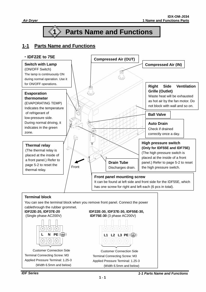
Terminal block
You can see the terminal block when you remove front panel. Connect the power
cablethrough the rubber grommet.
IDF22E-20, IDF37E-20 IDF22E-30, IDF37E-30, IDF55E-30,
(Single phase AC200V) IDF75E-30 (3 phase AC200V)
1
Parts Name and Functions
1-1 Parts Name and Functions
・IDF22E to 75E
Auto Drain
Check if drained
correctly once a day.
Compressed Air (OUT)
Compressed Air (IN)
Ball Valve
L N PE ( )
Customer Connection Side
Terminal Connecting Screw: M3
Applied Pressure Terminal: 1.25-3
(Width 6.5mm and below)
Thermal relay
(The thermal relay is
placed at the inside of
a front panel.) Refer to
page 5-2 to reset the
thermal relay.
L1 L2 L3 PE ( )
High pressure switch
(Only for IDF55E and IDF75E)
(The high pressure switch is
placed at the inside of a front
panel.) Refer to page 5-2 to reset
the high pressure switch.
Switch with Lamp
(ON/OFF Switch)
The lamp is continuously ON
during normal operation. Use it
for ON/OFF operations.
Evaporation
thermometer
(EVAPORATING TEMP)
Indicates the temperature
of refrigerant of
low-pressure side.
During normal driving, it
indicates in the green
zone.
Drain Tube
Discharges drain.
Right Side Ventilation
Grille (Outlet)
Waste heat will be exhausted
as hot air by the fan motor. Do
not block with wall and so on.
Front panel mounting screw
It can be found at left side and front side for the IDF55E, which
has one screw for right and left each (6 pcs in total).
Customer Connection Side
Terminal Connecting Screw: M3
Applied Pressure Terminal: 1.25-3
(Width 6.5mm and below)

IDX-OM-J034 Air Dryer 1 Name and Functions Parts
1-1 Parts Name and Functions 1 - 2
IDF Series
Front
Fixing Screw for Front Panel
Another one is on the right side.
Left Side Ventilation Grille (Inlet)
Breathe in cooling air from this grill.
Do not bung up with wall and so on.
Rubber Grommet
Power cord outlet
IDX-OM-J034 Air Dryer 2 Transportation / Installation
2-1 Transportation 2 - 1
IDF Series
2 Transportation / Installation
Warning Use the product in the right way. During Installation, operation, maintenance, and check,
you should be careful in keeping the safety of human body.
Caution Transportation, installation, and maintenance including dangerous work must be done by
a personnel who has enough knowledge and experience about the product and the
sysytem.
2-1 Transportation When you transport the product, you should follow these instructions below.
You should uplift the product from the base surface with careful attention to prevent falling sideways and
drop.
Do not bring the product lying sideways. If you lay it sideways, it will be broken.
Do not hang up the product.
Do not transport the product with any part such as an air filter mounted on the fittings at the air inlet or
outlet port of the product. If it is unavoidable to transport the product with such a part mounted, support
the part with a bracket to prevent the product from being affected by vibration during transportation.
Warning Those instructions above must be followed because the product is so heavy that it carries
a great risk to transport.
IDF22E to 75E are 54 to 116kg or more. They must be transported by more than 4 person, a
forklift and so on of IDF22E and IDF37E. They must be transported by forklift of IDF55E
and IDF75E.
IDX-OM-J034 Air Dryer 2 Transportation / Installation
2-2 Installation 2 - 2
IDF Series
2-2 Installation
2 - 2 - 1 Location The product should not be used or stored in the circumstances as follows.
Those circumstances will cause not only malfunction but also failures.
Environment where the product is
exposed to rainwater, moisture vapor,
salty water, oil and so on.
Locations where dust or particles are.
Locations where inflammable or
explosive gas are.
Locations where corrosive gas, solvent,
combustible gas are.
Locations that receive direct sunlight or
where radiant heat is generated.
Locations where ambient temperature
is beyond following range:
On-stream: 2 to 40oC
Storage: 0 to 50oC (when there is no
drain water inside of the piping)
Locations where temperature changes
rapidly.
Locations where strong
electromagnetic noise is generated
(locations where electromagnetic field,
strong magnetic field, surge is
generated)
Circumstances where static electricity
is produced or discharged through the
body of the product.
Locations where strong high frequency
wave is generated.
Locations where danger of thunder is
apparent.
Locations by loading on vehicles,
marine vessels, and so on.
Locations whose altitude is higher than
2,000 meters.
Circumstances where strong vibration
or impact are transmitted.
Circumstances where too much force
and weight are put on the body of the
product that causes it to deform.
Circumstances where enough spaces
cannot be taken to do maintenance (in
the plant where the product is
operated).
Spaces needed for maintenance
Front : 600 mm
Rear : 600 mm
Top : 600 mm
Right : 600 mm
Left : 600 mm
Locations the ventilation grille of the
product can be blocked.
Place where rejection style air of air
compressor or other driers (hot wind) is
inhaled.
Condition which has sudden
pressure/flow rate changes.
Warning Do not use and store in environment having compressed air or ambinet atmosphere which
includes the following substances. It could result in failure of the product and damage of
components, which leads to injury.
- Corrosive gas, Organic solvent, Chemicals
2 - 2 - 2 Anchorage
The air dryer should be installed on a vibration-free, stable, horizontal flat surface.
Refer to “Chapter6 6-3 Dimensions” for the dimensions.
Fix by bolts to prevent falling down. The bolts can be prepared separately as an accessory.
Model No. Name Quantity Applicable Model
IDF-AB500 Anchor bolt set 1(4pcs/1set) IDF22E,IDF37E,IDF55E,IDF75E
IDX-OM-J034 Air Dryer 2 Transportation / Installation
2-2 Installation 2 - 3
IDF Series
2 - 2 - 3 Air piping
Connection to the inlet and outlet of compressed air should be made removable by using union and so
on.
Pressing the hexagonal fitting with screw wrench and so on, connect the air piping fittings to the body.
When mounting any part such as an air filter on the fitting at the compressed air inlet or outlet port,
support the part to prevent excessive force from being applied to the product
Be careful not to let the vibration of the air compressor transmit.
If the temperature of compressed air on the inlet side is higher than 50oC, place an aftercooler after the
air compressor. Or, make the temperature of the place where the air compressor is installed lower than
50oC.
If the air supply makes high pressure fluctuation (pulsation), take any countermeasures such as
installing air tank.
Flash the piping sufficiently in order to avoid any foreign substances such as dust, sealing tape, liquid
gasket, etc. when piping before piping connection.Foreign substances in the piping can cause cooling
failure or drainage failure.
Use pipes and fittings that have enough endurance against the operating pressure and temperature.
And connect it firmly to prevent air leakage.
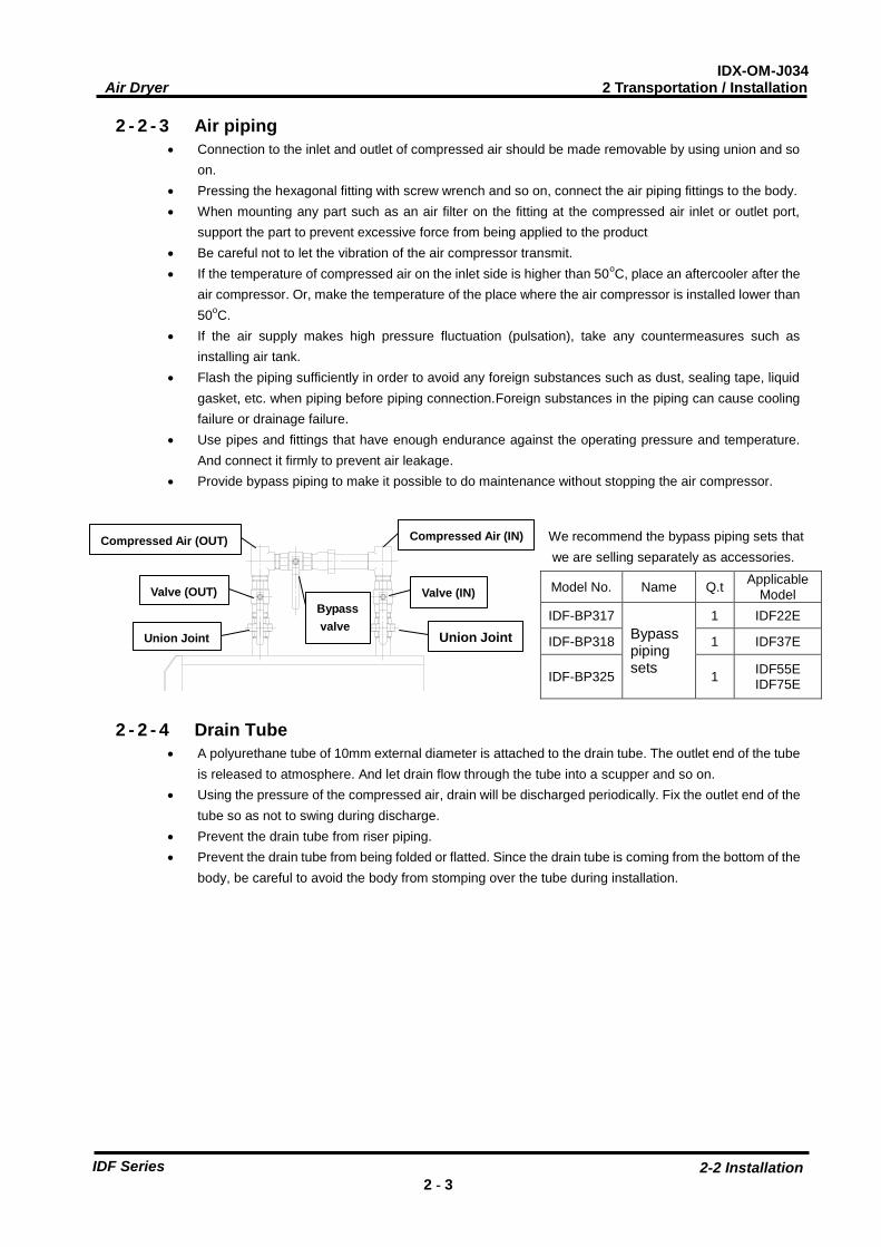
Provide bypass piping to make it possible to do maintenance without stopping the air compressor.
2 - 2 - 4 Drain Tube
A polyurethane tube of 10mm external diameter is attached to the drain tube. The outlet end of the tube
is released to atmosphere. And let drain flow through the tube into a scupper and so on.
Using the pressure of the compressed air, drain will be discharged periodically. Fix the outlet end of the
tube so as not to swing during discharge.
Prevent the drain tube from riser piping.
Prevent the drain tube from being folded or flatted. Since the drain tube is coming from the bottom of the
body, be careful to avoid the body from stomping over the tube during installation.
We recommend the bypass piping sets that
we are selling separately as accessories.
Model No. Name Q.t Applicable
Model
IDF-BP317
Bypass piping sets
1 IDF22E
IDF-BP318 1 IDF37E
IDF-BP325 1 IDF55E IDF75E
Compressed Air (OUT)
Compressed Air (IN)
Valve (IN) Valve (OUT)
Union Joint Union Joint
Bypass
valve

IDX-OM-J034 Air Dryer 2 Transportation / Installation
2-2 Installation 2 - 4
IDF Series
2 - 2 - 5 Electric Wiring
Warning No one but qualified person should do the wiring work.
・Before wiring, you must cut the power off for safety. Do not work under any energized
conditions.
・Supply power from a stable place, which is free from the effect of surge.
・Ensure that a Ground Fault Circuit Interrupter(GFCI) with appropriate capacity for earth
leakage and load is used in the power supply of the product to prevent electrical shock
and burnout of the compressor motor. See “6-1 List of specifications” for details.
・Supply power for the product should meet the specifications.
・The product should be grounded for safety.
・Do not connect the earth to a water pipe, a gas pipe, or a lightening rod.
・Do not plug too many leads into a single socket. That causes exothermic heat or fire.
・Do not convert the wiring to use.
・In European countries, a circuit breaker that meets the IEC standard should be used for
the supply power.
How to connect wiring
・Take off the front panel in front of the product and connect the power supply (AC200V) to the terminal base.
・Install a Ground Fault Circuit Interrupter(GFCI) to the power supply (Prepare by yourself)
[Sensed current: 30mA and below, Rated current 10A (Rated current 15A for IDF75E)]
Specification of power cable
Prepare following power cable.
Power cable: 1.25mm2(16AWG), External diameter: about 8 to 12mm
IDF22E-20, IDF37E-20(single phase power supply) …3 cores (including grounding)
IDF22E-30, IDF37E-30, IDF55E-30, IDF75E-30(3 phase power supply) …4 cores (including grounding)
Additional length of about 0.2m is needed to wire inside of the product.
Length of the power cable
The length of the power cable should extend less than 30m from the product.
Connecting to the power supply
Connect the power cable and the earth to the terminal block. M3 screw is used for the connection part. Make sure
to use round crimped terminal.
Applicable crimped terminal: 1.25-3 (Width: 6.5mm and below)
Wiring procedure
・Remove the front panel.
・Insert the cord through the rubber grommet and connect it to the terminal block (refer to the label on the terminal
block).
M3 screw tightening torque: 0.6 to 1Nm
During wiring work, do not touch other sections except terminal block.
・Attach the front panel as it were.

IDX-OM-J034 Air Dryer 2 Transportation / Installation
2-3 Cautions about Reinstallation 2 - 5
IDF Series
2-3 Cautions about Reinstallation
Caution
No one but someone who has enough knowledge about the product and incidental
devices should reinstall in another place. And following instructions must be executed.
If you move the product and reinstall it into another place after some operations (including trial running), instructions
that are not only following ones but also all of those in the chapter 2 should be followed.
Disassembly of the power cable
Cut off the power source when you disassemble the power cable.
Warning No one but qualified personnel should do the electric wiring.
Cut off the power supply for safety before the wiring. Do not work under energized
condition.
Disassembly of the air piping
Warning No one but qualified personnel should do the air piping.
Separate the compressor from the product for safety before removing the iping. Do not
remove any piping when there is remaining compressed air pressure inside of it. Remove the seal tape completely after detaching the piping. Remained tape will cause imperfect cooling
and failure by entering into the body of the product.
Residual compressed air pressure release procedure
Even while the dryer is removed, only when compressed air is needed, open the bypass piping valve.
Close the compressed air inlet and outlet valve.
Make sure the ball valve located next to the auto drain opened.
Open the auto drain residual pressure release valve to release air pressure inside the product. Refer to the
figure at right.
Case Assembly
The remainder depressure cock.
It opens when turning in the direction of the
arrow of figure.

IDX-OM-J034 Air Dryer 3 Operation / Shutdown
3-1 Check points before operation 3 - 1
IDF Series
3 Operation / Shutdown
Caution
No one but someone who has enough knowledge and experience about the product and
incidental devices should operate or shut down the product.
3-1 Check points before operation Before a trial running, check following points.
Installed Condition
By visual inspection check that the product is installed horizontally.
Make sure the product is fixed enough with anchor bolts.
Do not place heavy obstacles on the product and add unreasonable loading by piping and so on.
Wiring Connections
Power cord, and the earth should be connected firmly.
Drain Tube
Drain tube should be connected correctly.
Air Piping
Make sure the piping for compressed air is connected correctly. Those valves of IN / Out side and bypass piping
of the product and of the bypass piping should be completely fasten.
Ball valve
Make sure the ball valve located next to the auto drain opened.
3-2 Operation Start operation according to the procedure below.
Turn on the breaker of the main power supply. Then, turn on the illuminated switch.
The lamp will light up. Few minutes later, the cooling fan will rotate and hot air will be exhausted from the
ventilation grille.
Place of the ventilation grille: Right Side Ventilation Grille
Open the IN / Out side valve slowly. Make sure the bypass valve is completely closed. Make sure the bypass
valve is completely closed. Confirm there is no air leakage.
Depending on the condition of compressed air or ambient temperature, the cooling fan sometimes alternates
between rotation and stop at the beginning. Then, the refrigerator will go into continuous run and the pointer of
the evaporation thermometer will indicate in the green zone. If the pointer of the evaporation thermometer
indicates higher than the green zone, refer to “Chapter5 Troubleshooting.”
After a while from the start of flowing the compressed air, drain will be discharged from the drain tube
automatically.
Keep the condition of continuous run to use.

IDX-OM-J034 Air Dryer 3 Operation / Shutdown
3-3 Shutdown 3 - 2
IDF Series
Caution
・Avoid frequent On/Off operation, which can cause troubles.
・The auto drain used for the product has a structre that closes the valve with air pressure higher
than 0.15MPa. Therefore, until the pressure increase, air will be emitted form the drain outlet at
the begining of opening the IN side valve. Keep in mind that sometime the pressure cannot
increase enough with air compressor that has low dischage flow rate.
・Avoid using this product under the condition which has sudden pressure/flow rate changes.
Otherwise, drain (condensed water) may flow out to the secondary piping.
3-3 Shutdown Turn off the illuminated switch.
The lamp will go out and then, the operation will be stopped. Depending on the condition of operation, hot air
continues to be emitted from the ventilation grille by the cooling fan for a while after turning off the switch,
which is not an abnormality but a process for safety shutdown.
3-4 Cautions about restart One must wait for at least 3 minutes before restarting air dryer after it has been shut down. Failure to do this
may cause safety devices to trip due to over load.
If it is not possible to restart, refer to “Chapter 5 Troubleshooting.”
3-5 Check points before restart Check following points before you start operation. If any abnormalities occur, immediately stop the operation. Turn off the
illuminated switch of the product and then the breaker to the power supply.
There is no leakage of compressed air.
Compressed air pressure, temperature, flow rate, and ambient temperature meet the specifications.
Drain is being discharged from the drain tube.
The pointer of evaporation thermometer is indicating in the green zone.
Drainage should not be exhausted from the outlet of the air dryer.
There are no abnormal sound, vibration, or smelling.
3-6 Precautions for long-term non-operation If the product will not be operated for more than 24 hours, for example at the weekend, turn off the ILS (Switch
with lamp) or power supply, for energy saving and safety. It is also recommended to release the pressure and
residual drainage inside the compressed air piping and this air dryer.
The residual drainage in the air dryer may splash over the outlet when the operation is re-started, so it is
recommended to install a filter on the outlet of the air dryer.
IDX-OM-J034 Air Dryer 4 Maintenance
4-1 Daily Inspection 4 - 1
IDF Series
4 Maintenance
4-1 Daily Inspection Check following points during usual operations. If you find some problems, immediately stop the operation and refer to
“Chapter 5 Troubleshooting” as soon as possible.
There is no air leakage
The running lamp is lighting during operation
Drain is being discharged from drain tube
The pointer of the evaporation thermometer indicates in the green zone when it is running with pressurized air
supply.
The pointer of the evaporated thermometer indicates about 3 to 10oC lower than that of ambient temperature
when the product is suspended with no pressurized air supply.
There is no abnormal sound or vibration coming up from the product.
There are no abnormal smell or smoke coming up from the product.
4-2 Periodical Maintenance
4-2-1 Cleaning of ventilation grille (suction grille) Clean dust and other foreign particles from the ventilation area with vacuum cleaner or air blow nozzle once a
month.
Caution During air blowing, put on protective glass and mask to prevent dusts from coming into throat or eyes.
4-2-2 Service parts It is recommended to replace the following parts regularly. The interval values shown in this operation
manual depend on the operating conditions (ambient temperature, installation environment, etc.), so that
they are for reference.
Table 1. List of parts to be replaced regularly
Description Tecommended replacement interval
Pressure switch One Million times
Fan motor 20,000 hours
Magnetic Contactor , Magnetic Switch (Note) One Million times
*Note)If it is mounted by option ”T” (With terminal block for power supply , run , alarm signal and remote operation) or special order.
4-2-3 Cleaning of the case assembly
Remove the dust deposited in the auto drain case assembly every month. Use neutral detergent for cleaning. If the
degree of dirt is heavy and operating failure still continues even after cleaning, replace the product. Also, shorten
cleaning interval from the next time.
Part No. of case assembly
Part No. Name Quantity Applicable Model
AD48 Case Assembly 1 IDF22E, IDF37E IDF55E, IDF75E

IDX-OM-J034 Air Dryer 4 Maintenance
4-2 Periodical Maintenance 4 - 2
IDF Series
How to clean and replace the case assembly.
When carrying out maintenance work on the auto drain and auto drain strainer, please
follow the steps below.
・ Turn off the illuminated ON/OFF switch.
・ Disconnect the earth leakage breaker at the power supply or unplug the power plug from the socket.
・ Fully close the IN/OUT valves. Only open the bypass when compressed air is required during work.
・ Only the point that is necessary for work please remove a decoration panel.
・ Maintenance of the air dryer should only be carried out by someone with sufficient knowledge and
experience of air dryers and related equipment.
・ Before carrying out maintenance, the important warnings in this manual must be thoroughly read and
understood.
・ When replacing or cleaning parts of the air dryer, be sure to remove the compressed air pressure inside
the air dryer to “0”. Never remove the case assembly when the air dryer is operated or air pressure
remains inside. It is extremely dangerous if compressed air pressure remains inside the air dryer, as
parts may come flying off at speed when loosened, or other unexpected accidents.
・ This product has parts that become hot during operation and a power supply with high voltage applied.
There is a risk of burns due to heat or electrification by high voltage. Even when operation is shut down
after switching off the air dryer’s illuminated light, there are also charging lines. When working on the
charged sections, be sure to switch off the earth leakage breaker installed before starting work.
・ As some parts of the air dryer will remain hot, there is a risk of burns due to residual heat after the
power is switched off. So do not carry out replacement work until the temperature of these parts has
fallen to 50℃ or less. Wait for about 10 to 15 minutes as a guide.
・ When carrying out maintenance work on the auto drain strainer and auto drain, there is a risk of
touching the drain fluid during work. Please follow the safety procedure for operators specified by
customer.(Example: carry out work wearing safety glasses, apron and gloves to prevent discharged
fluid from touching the human body.)
・ Use neutral detergent solution to clean parts such as the auto drain strainer and auto drain. Never
use solvent such as thinner.
・ When removing the outer casing panel or case assembly of the auto drain, wear gloves to prevent
injuries.
Warning
Danger

IDX-OM-J034 Air Dryer 4 Maintenance
4-2 Periodical Maintenance 4 - 3
IDF Series
・ Close the ball valve.
・ Open the bleed valve by turning it anticlockwise to release
air left in the product.
・ Remove the drain tube from the case assembly.
・ Hold the case assembly lightly and pull down the lock button with
thumb. Then, turn the case assembly to the left (or right) to 45°to
align the marks,
Release your thumb from the lock button and slowly pull down the
case assembly (vertically) to remove it.
・ Pour solution of neutral detergent into the case assembly and
shake it well to clean.
・ Check the case O-ring for damage such as scratches, twisting or
foreign particles attached to it. Then, apply grease thinly and fit it
in the groove in the case assembly.
・ Fit the case assembly to the auto drain body. Turn it untill the lock
button clicks.
・ Try to turn the case assembly lightly and check that it does not
turn. If it turns, start with fitting the case assembly to the body
again.
・ Close the bleed valve by turning it clockwise and fit the
drain tube as it was.
・ Open the ball valve.
・ If the case assembly is damaged or very dirty, replace it
with a new one.
Pull down the case
assembly slowly
SO
Drain tube
release bush
Lock button
Drrain tube
Ball valve
Bleed valve
Ball valve
Float assembly
Turn to 45°
(right or left)
Auto drain strainer
Bleed valve
IDX-OM-J034 Air Dryer 5 Troubleshooting
5-1 Cause and countermeasure of errors 5 - 1
IDF Series
5 Troubleshooting
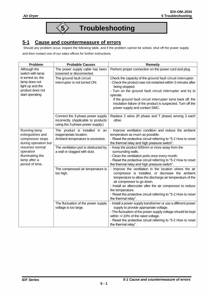
5-1 Cause and countermeasure of errors Should any problem occur, inspect the following table, and if the problem cannot be solved, shut off the power supply
and then contact one of our sales offices for further instructions.
Problem Probable Causes Remedy
Although the
switch with lamp
is turned on, the
lamp does not
light up and the
product does not
start operating.
The power supply cable has been
loosened or disconnected.
Perform proper connection on the power cord and plug.
The ground fault circuit
interrupter is not turned ON.
Check the capacity of the ground fault circuit interrupter.
- Check the product was not restarted within 3 minutes after
being stopped.
- Turn on the ground fault circuit interrupter and try to
operate.
If the ground fault circuit interrupter turns back off, the
insulation failure of the product is suspected. Turn off the
power supply and contact SMC.
Connect the 3-phase power supply
incorrectly. (Applicable to products
using the 3-phase power supply.)
Replace 2 wires (R phase and T phase) among 3 each
other.
Running lamp
extinguishes and
compressor stops
during operation but
resumes normal
operation
illuminating the
lamp after a
period of time.
The product is installed in an
inappropriate location.
Ambient temperature is excessive.
- Improve ventilation condition and reduce the ambient
temperature as much as possible.
- Reset the protective circuit referring to “5-2 How to reset
the thermal relay and high pressure switch”.
The ventilation port is obstructed by
a wall or clogged with dust.
- Keep the product 600mm or more away from the
surrounding walls.
- Clean the ventilation ports once every month.
- Reset the protective circuit referring to “5-2 How to reset
the thermal relay and high pressure switch”.
The compressed air temperature is
too high.
- Improve the ventilation in the location where the air
compressor is installed, or decrease the ambient
temperature to allow the discharge air temperature of the
air compressor to go down.
- Install an aftercooler after the air compressor to reduce
the temperature.
- Reset the protective circuit referring to “5-2 How to reset
the thermal relay”.
The fluctuation of the power supply
voltage is too large.
- Install a power supply transformer or use a different power
supply to provide appropriate voltage.
- The fluctuation of the power supply voltage should be kept
within +/-10% of the rated voltage.
- Reset the protective circuit referring to “5-2 How to reset
the thermal relay”.
IDX-OM-J034 Air Dryer 5 Troubleshooting
5-1 Cause and countermeasure of errors 5 - 2
IDF Series
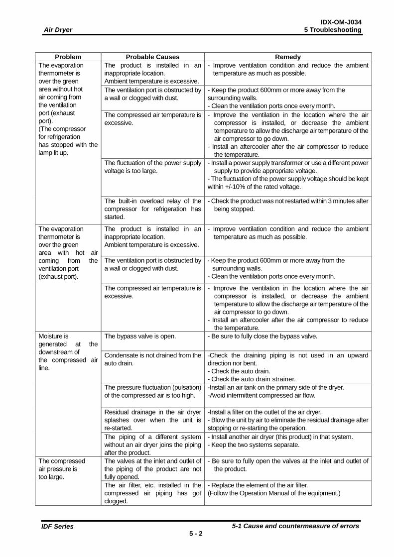
Problem Probable Causes Remedy
The evaporation
thermometer is
over the green
area without hot
air coming from
the ventilation
port (exhaust
port).
(The compressor
for refrigeration
has stopped with the
lamp lit up.
The product is installed in an
inappropriate location.
Ambient temperature is excessive.
- Improve ventilation condition and reduce the ambient
temperature as much as possible.
The ventilation port is obstructed by
a wall or clogged with dust.
- Keep the product 600mm or more away from the
surrounding walls.
- Clean the ventilation ports once every month.
The compressed air temperature is
excessive.
- Improve the ventilation in the location where the air
compressor is installed, or decrease the ambient
temperature to allow the discharge air temperature of the
air compressor to go down.
- Install an aftercooler after the air compressor to reduce
the temperature.
The fluctuation of the power supply
voltage is too large.
- Install a power supply transformer or use a different power
supply to provide appropriate voltage.
- The fluctuation of the power supply voltage should be kept
within +/-10% of the rated voltage.
The built-in overload relay of the
compressor for refrigeration has
started.
- Check the product was not restarted within 3 minutes after
being stopped.
The evaporation
thermometer is
over the green
area with hot air
coming from the
ventilation port
(exhaust port).
The product is installed in an
inappropriate location.
Ambient temperature is excessive.
- Improve ventilation condition and reduce the ambient
temperature as much as possible.
The ventilation port is obstructed by
a wall or clogged with dust.
- Keep the product 600mm or more away from the
surrounding walls.
- Clean the ventilation ports once every month.
The compressed air temperature is
excessive.
- Improve the ventilation in the location where the air
compressor is installed, or decrease the ambient
temperature to allow the discharge air temperature of the
air compressor to go down.
- Install an aftercooler after the air compressor to reduce
the temperature.
Moisture is
generated at the
downstream of
the compressed air
line.
The bypass valve is open. - Be sure to fully close the bypass valve.
Condensate is not drained from the
auto drain.
-Check the draining piping is not used in an upward
direction nor bent.
- Check the auto drain.
- Check the auto drain strainer.
The pressure fluctuation (pulsation)
of the compressed air is too high.
-Install an air tank on the primary side of the dryer.
-Avoid intermittent compressed air flow.
Residual drainage in the air dryer
splashes over when the unit is
re-started.
-Install a filter on the outlet of the air dryer.
- Blow the unit by air to eliminate the residual drainage after
stopping or re-starting the operation.
The piping of a different system
without an air dryer joins the piping
after the product.
- Install another air dryer (this product) in that system.
- Keep the two systems separate.
The compressed
air pressure is
too large.
The valves at the inlet and outlet of
the piping of the product are not
fully opened.
- Be sure to fully open the valves at the inlet and outlet of
the product.
The air filter, etc. installed in the
compressed air piping has got
clogged.
- Replace the element of the air filter.
(Follow the Operation Manual of the equipment.)

IDX-OM-J034 Air Dryer 5 Troubleshooting
5-2 How to reset the thermal relay and high pressure switch 5 - 3
IDF Series
++
+
+
5-2 How to reset the thermal relay and high pressure switch If light goes off during operation and refrigerating compressor stops, the thermal relay or high pressure switch
(for only the IDF55E and IDF75E) to protect the refrigerating compressor starts operating and needs to be
reset manually. For the position of the thermal relay and high pressure switch, refer to page 1-1.
Remove causes to start the thermal relay or high pressure switch referring to “5-1 Cause and countermeasure
for errors”.
Danger
Be sure to turn off the switch with light of the body.
How to reset a thermal relay
1. Turn off the switch with lamp of the body.
2. Take off the front panel. The thermal relay as shown on
right figure can be found on the power supply terminal base.
3. Confirm that a green indication does not appear at an
indication window of thermal relay.
If the green indication appears, there are other possible causes
and contact SMC with remaining the power supply on.
4. Press the blue reset button and confirm that the green
indication comes to appear at the indication window.
5. Put back the front panel.
6. When the switch with lamp is turned on, the product will restart
operation.
How to reset a high pressure switch
1. Turn off the switch with lamp of the body.
2. Take off the front panel. The high pressure switch can
be found at upper right part of power supply terminal base.
3. Press the red rest button.
4. Put back the front panel.
5. When the switch with lamp is turned on, the product will
restart operation.
Thermal relay
High pressure switch
High pressure
switch bracket Rest button
(Red)
Indication
window
Reset
button (Blue)
【IDF75E】
Reset
button (Blue)
【IDF22E~55E】
IDX-OM-J034 Air Dryer 6 References
6-1 Specifications 6 - 1
IDF Series
6
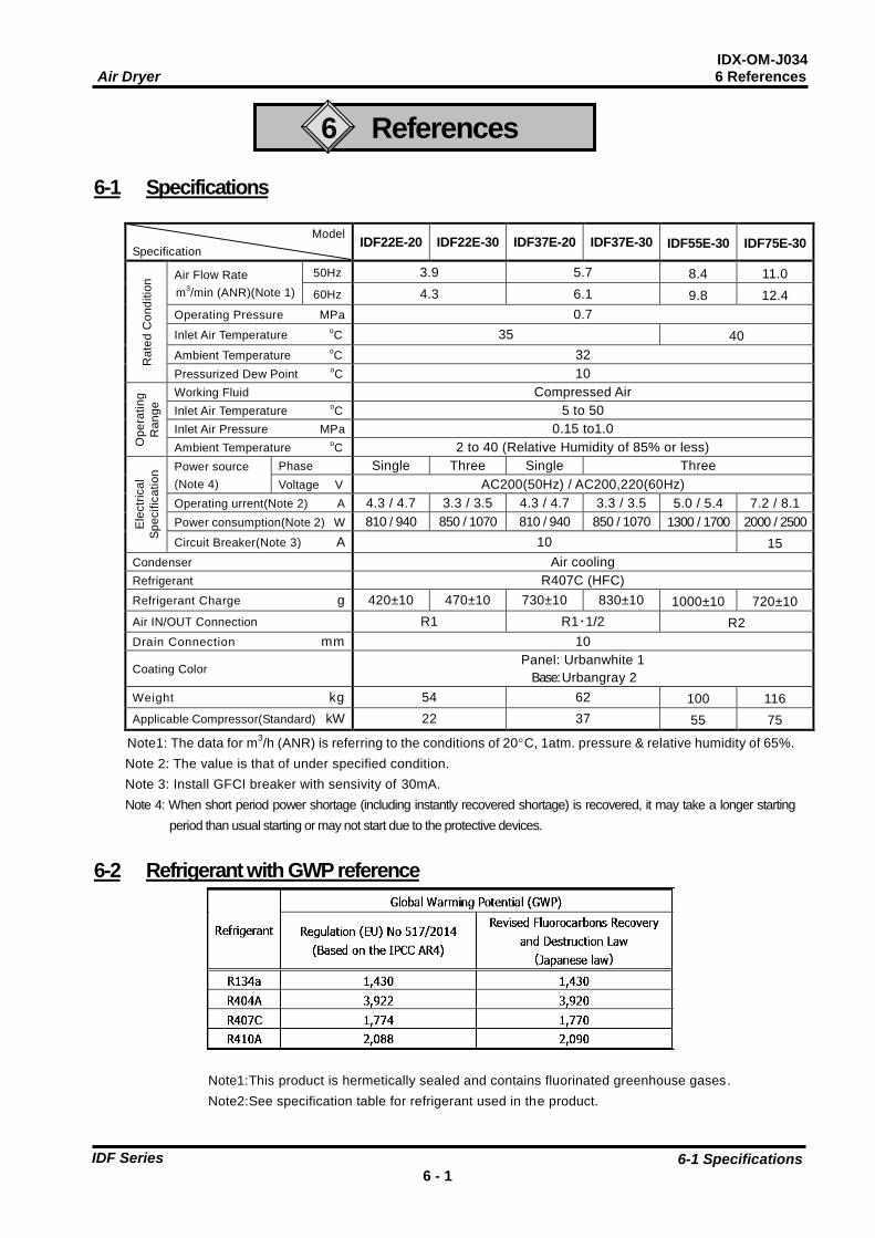
References 6-1 Specifications
Model
Specification IDF22E-20 IDF22E-30 IDF37E-20 IDF37E-30 IDF55E-30 IDF75E-30
Ra
ted
Co
nd
itio
n Air Flow Rate
m3/min (ANR)(Note 1)
50Hz 3.9 5.7 8.4 11.0
60Hz 4.3 6.1 9.8 12.4
Operating Pressure MPa 0.7
Inlet Air Temperature oC 35 40
Ambient Temperature oC 32
Pressurized Dew Point oC 10
Op
era
tin
g
Ra
ng
e Working Fluid Compressed Air
Inlet Air Temperature oC 5 to 50
Inlet Air Pressure MPa 0.15 to1.0
Ambient Temperature oC 2 to 40 (Relative Humidity of 85% or less)
Ele
ctr
ica
l
Sp
ecific
atio
n Power source
(Note 4)
Phase Single Three Single Three
Voltage V AC200(50Hz) / AC200,220(60Hz)
Operating urrent(Note 2) A 4.3 / 4.7 3.3 / 3.5 4.3 / 4.7 3.3 / 3.5 5.0 / 5.4 7.2 / 8.1
Power consumption(Note 2) W 810 / 940 850 / 1070 810 / 940 850 / 1070 1300 / 1700 2000 / 2500
Circuit Breaker(Note 3) A 10 15
Condenser Air cooling
Refrigerant R407C (HFC)
Refrigerant Charge g 420±10 470±10 730±10 830±10 1000±10 720±10
Air IN/OUT Connection R1 R1・1/2 R2
Drain Connection mm 10
Coating Color Panel: Urbanwhite 1
Base: Urbangray 2
Weight kg 54 62 100 116
Applicable Compressor(Standard) kW 22 37 55 75
Note1: The data for m3/h (ANR) is referring to the conditions of 20C, 1atm. pressure & relative humidity of 65%.
Note 2: The value is that of under specified condition.
Note 3: Install GFCI breaker with sensivity of 30mA.
Note 4: When short period power shortage (including instantly recovered shortage) is recovered, it may take a longer starting
period than usual starting or may not start due to the protective devices.
6-2 Refrigerant with GWP reference
Note1:This product is hermetically sealed and contains fluorinated greenhouse gases.
Note2:See specification table for refrigerant used in the product.
IDX-OM-J034 Air Dryer 6 References
6-3 Dimentions 6 - 2
IDF Series
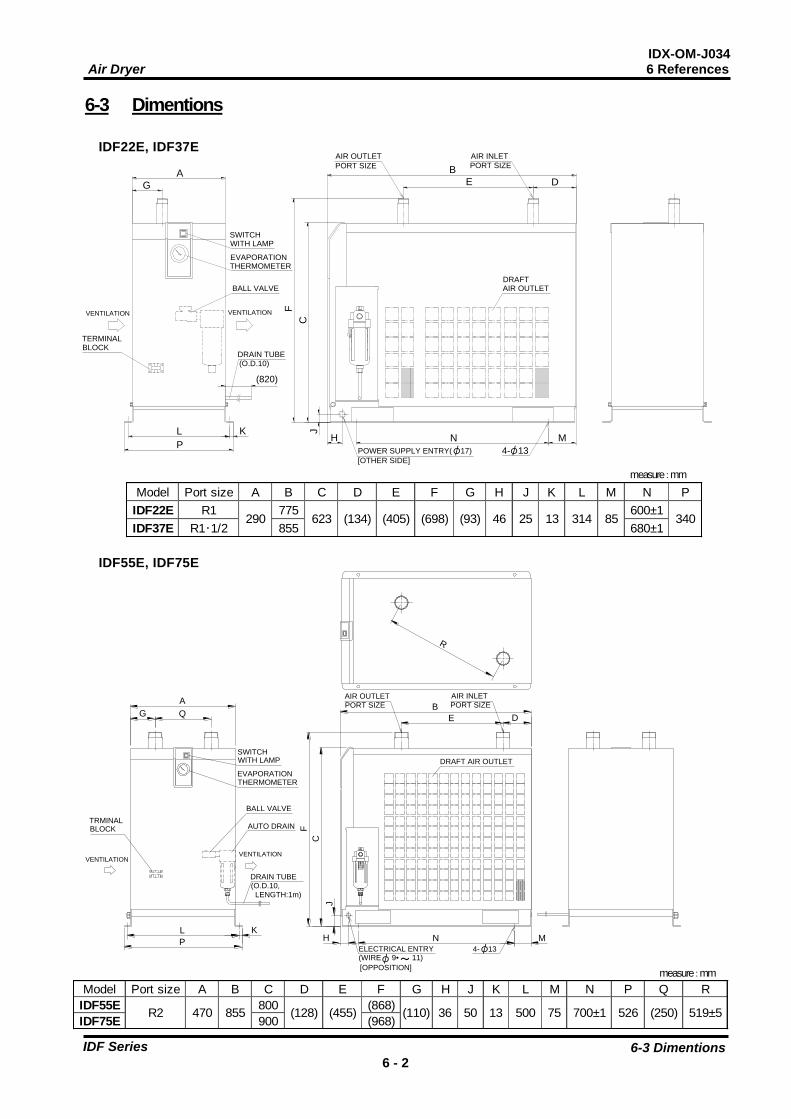
6-3 Dimentions
IDF22E, IDF37E
IDF55E, IDF75E
measure:mm
measure:mm
(820)
4- 13POWER SUPPLY ENTRY( 17)
[OTHER SIDE]
AIR OUTLET
PORT SIZE
AIR INLET
PORT SIZE
AIR OUTLET
WITH LAMP
THERMOMETER
BLOCK
VENTILATION
DRAIN TUBE(O.D.10)
BALL VALVE
VENTILATION
SWITCH
EVAPORATION
TERMINAL
DRAFT
A
G
L
P
K J
H N M
B
E D
F
C
φ φ
Model Port size A B C D E F G H J K L M N P
IDF22E R1 775 600±1
IDF37E R1・1/2 855 680±1290 623 (134) (405) (698) (93) 46 25 13 314 85 340
Model Port size A B C D E F G H J K L M N P Q R
IDF55E 800 (868)
IDF75E 900 (968)R2 470 855 (128) (455) (110) 36 50 526 (250) 519±513 500 75 700±1
Q
L
P
K
VENTILATIONVENTILATION
R
B
E D
F
C
J
H N M
G
A
BLOCKTRMINAL
WITH LAMPSWITCH
THERMOMETEREVAPORATION
BALL VALVE
AUTO DRAIN
DRAIN TUBE(O.D.10,
LENGTH:1m)
AIR OUTLET
PORT SIZE PORT SIZE
AIR INLET
ELECTRICAL ENTRY
[OPPOSITION]
(WIRE 9• ̀ 11)4- 13
DRAFT AIR OUTLET
φ φ ~

IDX-OM-J034 Air Dryer 6 References
6-4 Electrical Circuit 6 - 3
IDF Series
6-4 Electrical Circuit
SYMBOL DESCRIPTION SYMBOL DESCRIPTION SYMBOL DESCRIPTION
CM Refrigerating Compressor PRR Phase Revarsal Relay OLR Over Load Relay
FM Fan Motor For Condenser PRS Pressure Switch THP Thermal Protector For FM
MC Magnetic Contactor PRS1 Pressure Switch TB Terminal Block
MC1 Magnetic Contactor PRS2 High Pressure Switch GFCI Ground Fault Circuit Interrupter
MC2 Magnetic Contactor ILS Switch with Lamp MOV Motor Operated Valve
C01 Capacitor For CM THR Thermal Relay
C11 Capacitor For FM THS Thermostat
IDF22E-20, IDF37E-20 IDF22E-30, IDF37E-30
IDF55E-30 IDF75E-30
For Option R
GFCI
ILS
CM
FM
LTB
N PE
MC
C01
C11
PRS
P
THR
THR
OLR
オプションMの場合 For Option M
MC1
P
PRS1
THR
FM
MC2
THS
PRR
THPθ
CM
TB
θ
P
PRS2THRPRR
MC2
GFCIGFCI
For Option R
For Option M
MC1
P
PRS1
THR
FM
MC2
PRR
THP
CM
TB
θ
P
PRS2THRPRR
MC2
GFCIGFCI
For Option R
For Option M
P
TBL1 L3L2 PE
PRR
ILS
MC
OLP1
OLP2
MC
MC PRR
CM
MOV
FMC11
PRS
GFCI For Option R
For Option M

IDX-OM-J034 Air Dryer 6 References
6-5 Compressed Air and Refrigerant Circuit / Operation Principles 6 - 4
IDF Series
6-5 Compressed Air and Refrigerant Circuit / Operation Principles
Compressed Air Circuit
Hot and humid air which has come in an air dryer firstly enters reheating part, exchanges its heat with dehumidified cold
air and becomes cooler. Then, it enters cooling part and gives its heat to cold fleon, which cools and dehumidifies
further, and separates its moisture. Finally, it exchanges its heat with hot and humid air which comes in the air dryer and
goes out from the air dryer as warm and dry air.
Refrigerant Circuit
The Fluorocarbon charged in the refrigerant circuit is compressed by the compressor and cooled by the condenser to
become liquid. Then, going through the capillary tube, it is decreased the pressure to reach a low temperature. Passing
through the cooler part, it draws heat from compressed air and intensely boils. Finally it is inhaled into the compressor
again. The capacity control valve opens to prevent dew drops from freezing when compressed air is cooled enough.
Drain
IDX-OM-J034
Air Dryer 7 Specification for Option A
7-1 Safety instructions
7- 1
IDF Series
7
Specification for Option A
7-1 Safety instructions
When handling the product, take care to the following precautions.
Warning
Shut off the power supply when removing the panel for maintenance work, etc. The product
has a fan(s) and could cause serious danger to operators.
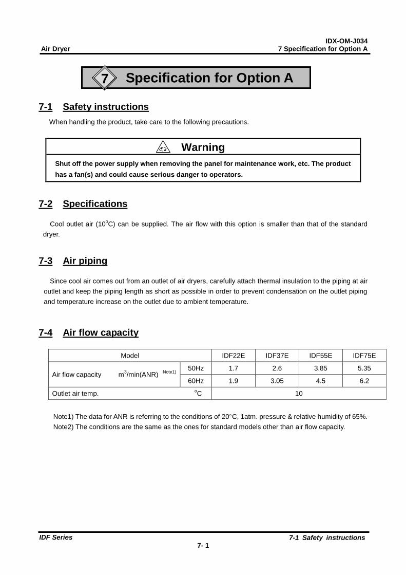
7-2 Specifications
Cool outlet air (10oC) can be supplied. The air flow with this option is smaller than that of the standard
dryer.
7-3 Air piping
Since cool air comes out from an outlet of air dryers, carefully attach thermal insulation to the piping at air
outlet and keep the piping length as short as possible in order to prevent condensation on the outlet piping
and temperature increase on the outlet due to ambient temperature.
7-4 Air flow capacity
Note1) The data for ANR is referring to the conditions of 20C, 1atm. pressure & relative humidity of 65%.
Note2) The conditions are the same as the ones for standard models other than air flow capacity.
Model IDF22E IDF37E IDF55E IDF75E
Air flow capacity m3/min(ANR)
Note1)
50Hz 1.7 2.6 3.85 5.35
60Hz 1.9 3.05 4.5 6.2
Outlet air temp. oC 10

IDX-OM-J034
Air Dryer 7 Specification for Option A
7-5 Compressed Air and Refrigerant Circuit / Operation Principles
7- 2
IDF Series
7-5 Compressed Air and Refrigerant Circuit / Operation Principles
Capillary Tube
Condenser
Cooler
Drain Outlet
Compressed Air Inlet
Auto Drain
Thermoreter
Accmulator
Compressor
Fan Motor
Ball Valve
High Pressure Switch
Capacity Control Valve
Compressed Air Outlet
Pressure Switch
Compressed Air Circuit
The heat of humid hot air entering to the air drier enters to the cooler and is cooled and
dehumidified by cold fleon, separating the moisture.
The cold air is released from the air dryer.
Refrigerant Circuit
The Fluorocarbon charged in the refrigerant circuit is compressed by the compressor and
cooled by the condenser to become liquid. Then, going through the capillary tube, it is
decreased the pressure to reach a low temperature. Passing through the cooler part, it
draws heat from compressed air and intensely boils. Finally it is inhaled into the
compressor again. The capacity control valve opens to prevent dew drops from freezing
when compressed air is cooled enough.
Except IDF75E

IDX-OM-J034 Air Dryer 7 Specification for Option C
8-1 Safety instructions
8- 1
IDF Series
8
Specification for Option C
8-1 Safety instructions
When handling the product, take care to the following precautions.
Warning
Shut off the power supply when removing the panel for maintenance work, etc. The product
has a fan(s) and could cause serious danger to operators.
8-2 Specifications
The surface of copper tube is painted with a special epoxy resin for the rust proofing. The parts covered
with aluminum fins and insulations are not painted.
8-3 Precautions for the installation and handling of the product
1) The surface of cooper tube is painted with a special epoxy to improve the rust proof effect from
corrosive gas, but it is not perfect rust proof. Therefore, avoid installing the product in the place
exposed to corrosive gas as much as possible.
2) If any of the painted surfaces of copper tube is damaged, such as when the panels are removed for
maintenance, the effect of its rust proofing painting is lost. Do not give damage any painted surfaces of
copper tube.
IDX-OM-J034 Air Dryer 8 Specification for Option K
9-1 Safety instructions
9- 1
IDF Series
9
Specification for Option K
For IDE22E/37E
9-1 Safety instructions
When handling the product, take care to the following precautions.
Warning - Do not remove the auto drain with the air pressure remaining internally. If the compressed
air is left in the product, when some part is loosened, it may cause sudden lurching or other unexpected accidents.
- When removing the panel, wear protective gloves to prevent injuries.
- There is a risk of touching drained waste liquid during replacement.
When draining, follow the user’s own procedure to keep operators safe. (E.g. Wear
protective goggles, apron and gloves to prevent contact with the drained condensate.)
- When oils can enter the drained condensate, waste water treatment is necessary. Follow the
bylaws or rules of the local municipality for disposal.
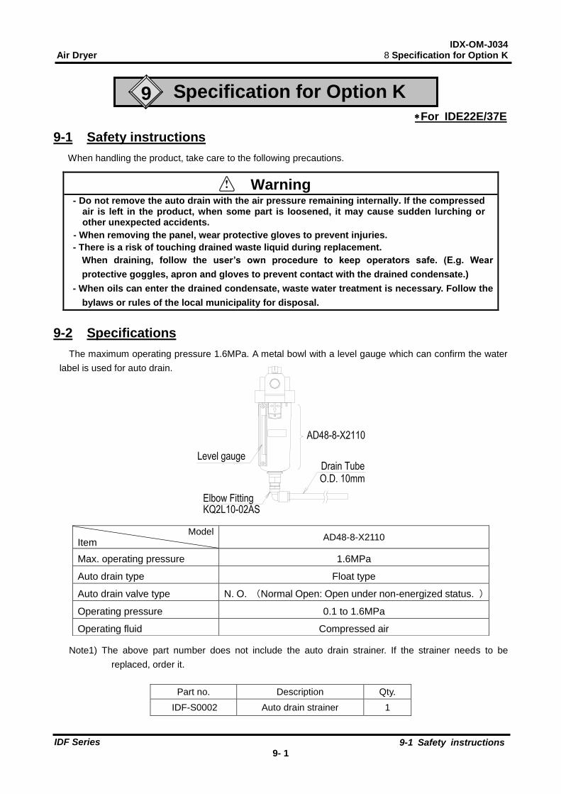
9-2 Specifications
The maximum operating pressure 1.6MPa. A metal bowl with a level gauge which can confirm the water
label is used for auto drain.
Note1) The above part number does not include the auto drain strainer. If the strainer needs to be
replaced, order it.
Model
Item AD48-8-X2110
Max. operating pressure 1.6MPa
Auto drain type Float type
Auto drain valve type N. O. (Normal Open: Open under non-energized status. )
Operating pressure 0.1 to 1.6MPa
Operating fluid Compressed air
Part no. Description Qty.
IDF-S0002 Auto drain strainer 1

IDX-OM-J034 Air Dryer 10 Specification for Option L
10-1 Safety instructions 10- 1
IDF Series
10 Specification for Option L
10-1 Safety instructions
When handling the product, take care to the following precautions.
Warning - Do not remove the auto drain with the air pressure remaining internally. If the compressed
air is left in the product, when some part is loosened, it may cause sudden lurching or
other unexpected accidents.
- When removing the panel, wear protective gloves to prevent injuries.
- There is a risk of touching drained waste liquid during replacement.
When draining, follow the user’s own procedure to keep operators safe. (E.g. Wear
protective goggles, apron and gloves to prevent contact with the drained condensate.)
- When oils can enter the drained condensate, waste water treatment is necessary. Follow the
bylaws or rules of the local municipality for disposal.
10-2 Specifications
The maximum operating pressure 1.6MPa. The float type auto drain used in the standard air dryer is
replaced with a heavy duty auto drain (ADH4000-04).
Heavy duty auto drain assembly
Model Item
IDF22E--L IDF37E--L IDF55E--L IDF75E--L
Auto drain type Floating type
Auto drain valve type N.O.(normally opened: Released without pressurization)
Working pressure range 0.05 to 1.6MPa
Max. drain discharge 400cc/min(Pressure 0.7MPa, the case of water)
Note) Use for air compressor with flow more than 50L/min (ANR).
Heavy duty auto drain
(ADH4000-04)Ball valve
Drain tube
O.D. 10mm

IDX-OM-J034 Air Dryer 10 Specification for Option L
10-3 Maintenance 10- 2
IDF Series
10-3 Maintenance
1) As a preventive maintenance, press the flush button of the heavy-duty auto drain regularly to clean the
discharge valve (for flushing).
2) The pilot exhaust of the heavy-duty auto drain is at the position shown in the figure. Do not close the
exhaust port. Also, clean the exhaust port to prevent it from getting blocked by dust.
3) Close the ball valve before removing the heavy duty auto drain and open the bleed valve or push the
flushing button and confirm air pressure is released.
Flush button
Body
Bleed valve
Pilot exhaust port
open close
IDX-OM-J034 Air Dryer 11 Specification for Option M
11-1 Safety instructions 11- 1
IDF Series
11 Specification for Option M
11-1 Safety instructions
When handling the product, take care to the following precautions.
Warning - Do not remove the auto drain with the air pressure remaining internally. If the compressed
air is left in the product, when some part is loosened, it may cause sudden lurching or
other unexpected accidents.
- When removing the panel, wear protective gloves to prevent injuries.
- There is a risk of touching drained waste liquid during replacement.
When draining, follow the user’s own procedure to keep operators safe. (E.g. Wear
protective goggles, apron and gloves to prevent contact with the drained condensate.)
- When oils can enter the drained condensate, waste water treatment is necessary. Follow the
bylaws or rules of the local municipality for disposal.
Warning Only qualified persons are allowed to wire the product.
- Use a power supply suitable for the specifications of the product.
- Be sure to connect the ground connection.
- Grounding should never be connected to a water line, gas line or lightning rod.
- Multiple wiring is dangerous because it may lead to heat generation and cause a fire.
- Do not modify the electrical wiring of the power supply.

IDX-OM-J034 Air Dryer 11 Specification for Option M
11-2 Specifications 11- 2
IDF Series
auto drainMotor type
Drain tube
Ball valve
(O.D.10,LENGTH:0.95m)
11-2 Specifications
The float type auto drain used in the standard air dryer is replaced with a motor type auto drain (ADM200).
The customer is required to mount the auto drain to the air dryer.
11-3 Cautions for handling the motor type auto drain
Check drain condition periodically (more than once a day).
Then push manual button to open exhaust valve.
11-4 Electric circuit
For electric circuit, refer to ’’6-4 Electric circuit’’.
Please refer to ’’13-6 Electric circuit’’ when option T is included.
Model
Items IDF22E--M IDF37E--M IDF55E--M IDF75E--M
Parts number IDF-S0090
Max. operating pressure 1.0MPa
Operating fluid Compressed air
Operating cycle Once every minute
Operating time 2 seconds/cycle
Power supply voltage of dryer AC200V(50/60Hz)
Power consumption 4W

IDX-OM-J034 Air Dryer 12 Specification for Option R
12-1 Safety instructions
12- 1
IDF Series
12 Specification for Option R
12-1 Safety instructions
When handling the product, take care to the following precautions.
Warning Only qualified persons are allowed to wire the product.
- Before wiring, be sure to shut off the power supply. Never perform wiring work while the
product is energized.
- Ensure a stable power supply with no voltage surges.
- Use a power supply suitable for the specifications of the product.
- Be sure to connect the ground connection.
- Grounding should never be connected to a water line, gas line or lightning rod.
- Multiple wiring is dangerous because it may lead to heat generation and cause a fire.
- Do not modify the electrical wiring of the power supply.
12-2 Specifications
Customer should connect power cords at primary side of ground fault circuit interrupter, which is different
from standard such as plug-in type (AC100V) or terminal block type (AC200V). The ground fault circuit
interrupter is located at the rear side (air inlet and outlet side).
Model Item
IDF22E--R IDF37E--R IDF55E--R IDF75E--R
Current rating (A) 10 15
Sensitivity current (mA) 30
IDX-OM-J034 Air Dryer 12 Specification for Option R
12-3 Power supply connection procedure
12- 2
IDF Series
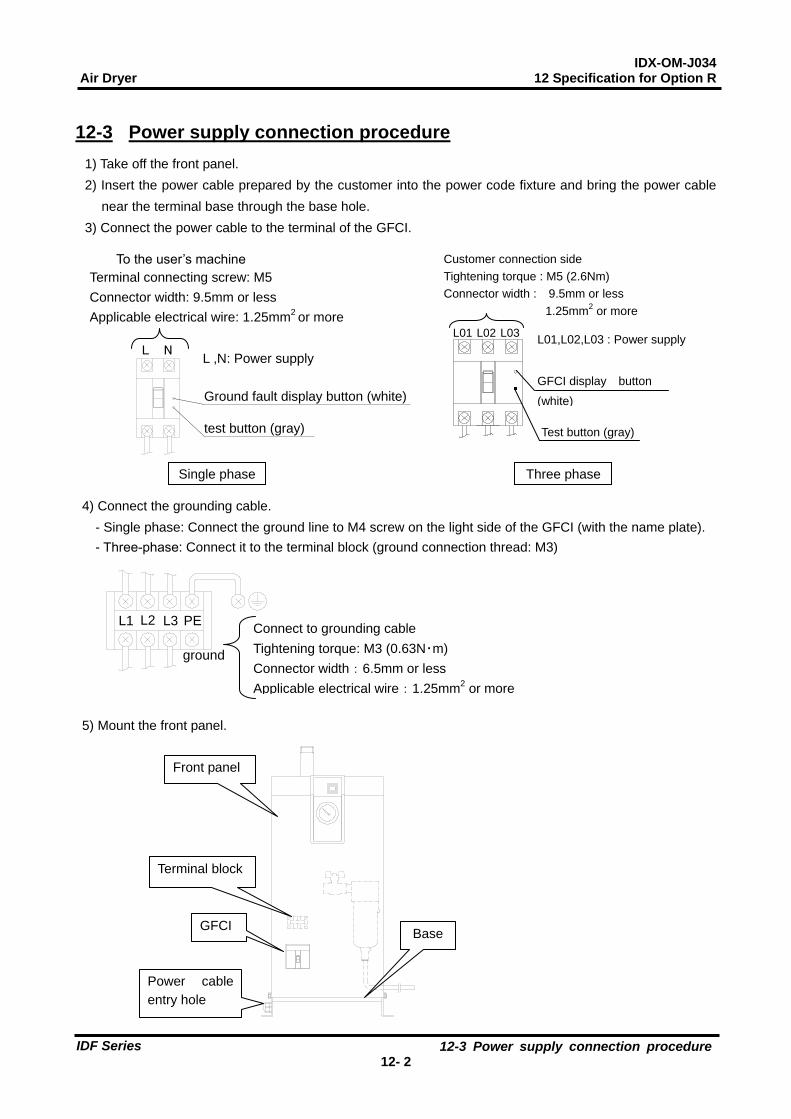
12-3 Power supply connection procedure
1) Take off the front panel.
2) Insert the power cable prepared by the customer into the power code fixture and bring the power cable
near the terminal base through the base hole.
3) Connect the power cable to the terminal of the GFCI.
4) Connect the grounding cable.
- Single phase: Connect the ground line to M4 screw on the light side of the GFCI (with the name plate).
- Three-phase: Connect it to the terminal block (ground connection thread: M3)
5) Mount the front panel.
Customer connection side
Tightening torque : M5 (2.6Nm)
Connector width : 9.5mm or less
1.25mm2 or more
Test button (gray)
GFCI display button
(white)
L01,L02,L03 : Power supply L03L02L01
Three phase
Front panel
GFCI
Power cable
entry hole
Terminal block
Base
PEL3L2L1
ground
Connect to grounding cable
Tightening torque: M3 (0.63N・m)
Connector width:6.5mm or less
Applicable electrical wire:1.25mm2 or more
To the user’s machine
Terminal connecting screw: M5
Connector width: 9.5mm or less
Applicable electrical wire: 1.25mm2 or more
L ,N: Power supply NL
Ground fault display button (white)
test button (gray)
Single phase
IDX-OM-J034 Air Dryer 12 Specification for Option R
12-4 Cautions for handling the GFCI
12- 3
IDF Series
12-4 Cautions for handling the GFCI
1) When the breaker is tripped, cut off the power supply and contact the nearest sales distributor or SMC sales.
- With the Ground fault display button (white) released → Current leakage
- With the Ground fault display button (white) pressed → Over current
2) Check the operation once a month by pressing the test button (gray) with the breaker on and Switch with Lamp off.
12-5 Electric circuit
For electric circuit, refer to ’’6-4 Electric circuit’’.
Please refer to ’’13-6 Electric circuit’’ when option T is included.
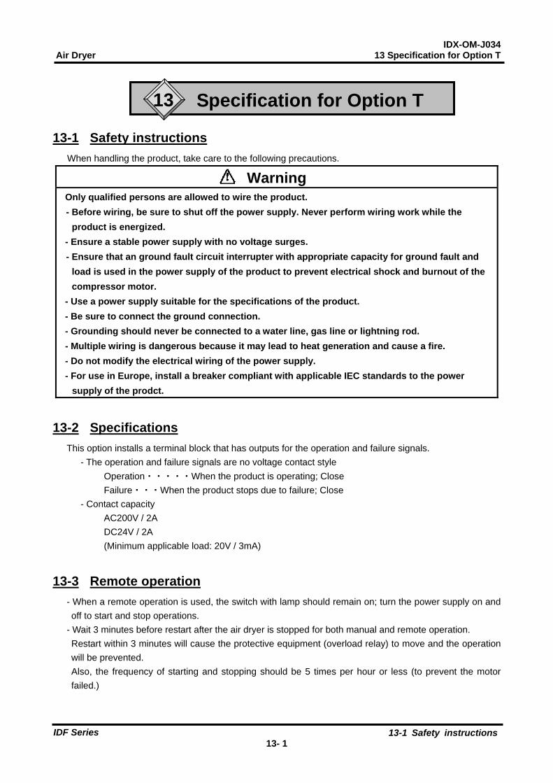
IDX-OM-J034 Air Dryer 13 Specification for Option T
13-1 Safety instructions
13- 1
IDF Series
13 Specification for Option T
13-1 Safety instructions
When handling the product, take care to the following precautions.
Warning Only qualified persons are allowed to wire the product.
- Before wiring, be sure to shut off the power supply. Never perform wiring work while the
product is energized.
- Ensure a stable power supply with no voltage surges.
- Ensure that an ground fault circuit interrupter with appropriate capacity for ground fault and
load is used in the power supply of the product to prevent electrical shock and burnout of the
compressor motor.
- Use a power supply suitable for the specifications of the product.
- Be sure to connect the ground connection.
- Grounding should never be connected to a water line, gas line or lightning rod.
- Multiple wiring is dangerous because it may lead to heat generation and cause a fire.
- Do not modify the electrical wiring of the power supply.
- For use in Europe, install a breaker compliant with applicable IEC standards to the power
supply of the prodct.
13-2 Specifications
This option installs a terminal block that has outputs for the operation and failure signals.
- The operation and failure signals are no voltage contact style
Operation・・・・・When the product is operating; Close
Failure・・・When the product stops due to failure; Close
- Contact capacity
AC200V / 2A
DC24V / 2A
(Minimum applicable load: 20V / 3mA)
13-3 Remote operation
- When a remote operation is used, the switch with lamp should remain on; turn the power supply on and
off to start and stop operations.
- Wait 3 minutes before restart after the air dryer is stopped for both manual and remote operation.
Restart within 3 minutes will cause the protective equipment (overload relay) to move and the operation
will be prevented.
Also, the frequency of starting and stopping should be 5 times per hour or less (to prevent the motor
failed.)

IDX-OM-J034 Air Dryer 13 Specification for Option T
13-4 How to connect the power and signal cable
13- 2
IDF Series
13-4 How to connect the power and signal cable
Connect the power cable and signal cable in the following procedures.
1) Take off the front panel.
2) Insert the power cable prepared by the customer into the power cord inlet (with rubber grommet)
and bring the power cable near the terminal block through the base hole.
3) Connect the power cable to the terminal.
4) Insert the signal cable prepared by the customer into the signal cord inlet (with rubber grommet)
and bring the signal cable near the terminal block.
5) Connect the signal cable to the each terminal.
6) Put back the front panel.
13-5 How to re-start the operation
The output of the abnormal signal can be stopped by turning off the switch with light. Remove the cause of abnormal operation and leave it for 3 minutes or longer after the stopping the operation, and turn on the switch with light to re-start. The thermal relay
is still in operation if the output of the abnormal signal is not stopped even after the
switch with light is turned off. Refer to “5-2. How to reset the thermal relay and high pressure switch” in the operation manual, and reset it. Note ) The high pressure switch can also be in operation for IDF55E-30 and IDF75E-30.
Connections for customer
NL
Failure
PE:Ground Operation
1 2 3
L,N:Power supply
PE
Terminal screw : M3
(Tighten torque 0.6 Nm to 1.0Nm)
Connecter width: 6.5mm or less
Suitable wire
Power cable: 1.25mm2 to 2mm
2
Signal cable: 0.5 mm2 to 2mm
2
Single phase
L1 L2 PE 1 2 3
Power Supply Failure
GroundOperation
L3
Connections for customer
Rubber grommet
Power supply cable entry
Rubber grommet
Signal cable outlet
Three phase
Front panel
You can see the terminal block when you remove this cover.

IDX-OM-J034 Air Dryer 13 Specification for Option T
13-6 Electric circuit
13- 3
IDF Series
13-6 Electric circuit
IDF22/37E-20-T IDF22/37E-30-T
IDF55E-30-T IDF75E-30-T
SYMBOL DESCRIPTION SYMBOL DESCRIPTION SYMBOL DESCRIPTION
CM Refrigerating Compressor PRR Phase Revarsal Relay OLR Over Load Relay
FM Fan Motor For Condenser PRS Pressure Switch THP Thermal Protector For FM
MC Magnetic Contactor PRS1 Pressure Switch TB Terminal Block
MC1 Magnetic Contactor PRS2 High Pressure Switch GFCI Ground Fault Circuit Interrupter
MC2 Magnetic Contactor ILS Switch with Lamp MOV Motor Operated Valve
C01 Capacitor For CM THR Thermal Relay TDR Time Delay Relay
C11 Capacitor For FM THS Thermostat
PRS
P
TB
ILS
GFCI
PRR
MC TDR
L1 2 31L2 L3 PE
MCMC PRR
OLP1OLP2
MC
MOV
CM
FMC11
MCTDR
For Option R Operation Failure
For Option M
ILS
CM
FM
LTB
N PE
MCC01
C11
PRS
P
THR
THR
TB1 2 3
異常信号
OLR
MOV
GFCI
For Option R
For Option M
Operation Failure
TB
P
PRS1
MC1THR
FM
MC2
THS
1 2 3
MC1 TDR
TDR
PRR
THPθ
CM
MC1
THRPRR
P
PRS2
MC2
MC1
運転信号 異常信号
θ
GFCI
オプションMの場合
Operation Failure
GFCI
For Option R
For Option M
TB
P
PRS1
MC1THR
FM
MC2
1 2 3
MC1 TDR
TDR
PRR
THP
CM
MC1
THRPRR
P
PRS2
MC2
MC1
運転信号 異常信号
θ
OLR
GFCI
Operation Failure
For Option M
GFCI
For Option R
THR
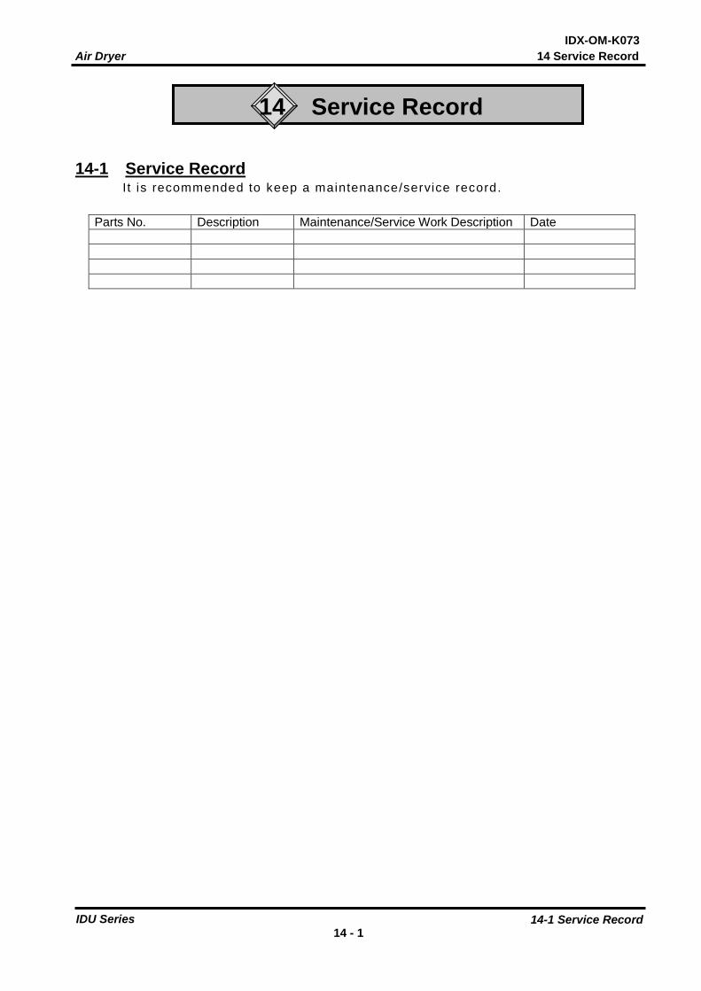
Air Dryer 14 Service Record
14-1 Service Record 14 - 1
IDU Series
IDX-OM-K073
14 Service Record
14-1 Service Record I t is recommended to keep a maintenance/service record.
Parts No. Description Maintenance/Service Work Description Date

Akihabara UDX 15F,
4-14-1, Sotokanda, Chiyoda-ku, Tokyo 101-0021, JAPAN
Tel: +81 3 5207 8249 Fax: +81 3 5298 5362
URL: http://www.smcworld.com
Specifications are subject to change without prior notice and any obligation the part of the manufacturer.
2017 SMC Corporation All Rights Reserved


