
100 CATALOG | Photoelectric Sensors
(*)
S9NC ATA L O G S E C T I O N
S300 PAThrough beam 0…50 m
Retroreflective (on R2 reflector) 0,1…15 m
Polarized retroreflective 0,1…10 m
Diffuse proximity 0,05...2 m
Background suppression 0,2...2 m
Power supplyVdc 12…30 VVacVac/dc 24…240 Vac/24…60 Vdc
Output
PNPNPNNPN/PNP •relay •other
Connectioncableconnector •pig-tail
Approximate dimensions (mm) 25x100x70
Housing material PBT
Mechanical protection IP67
(*)DC models: ATEX II 3DG
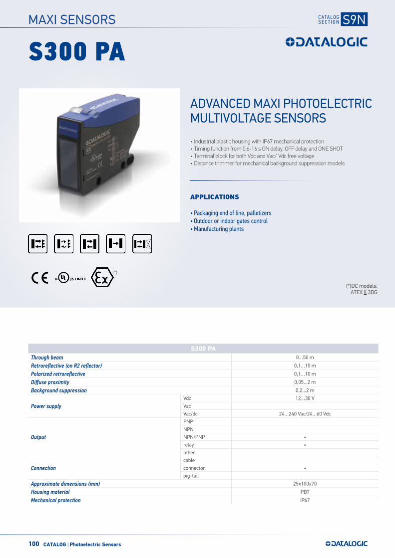
S300 PA
• Industrial plastic housing with IP67 mechanical protection• Timing function from 0.6-16 s ON delay, OFF delay and ONE SHOT• Terminal block for both Vdc and Vac/ Vdc free voltage• Distance trimmer for mechanical background suppression models
APPLICATIONS
• Packaging end of line, palletizers• Outdoor or indoor gates control• Manufacturing plants
ADVANCED MAXI PHOTOELECTRIC MULTIVOLTAGE SENSORS
MAXI SENSORS
101CATALOG | Photoelectric Sensors
S300-PA SERIES INSTRUCTION MANUAL
CONTROLS
OUTPUT LED (yellow) The yellow LED ON indicates the output status. STABILITY LED (green) The green LED ON indicates that the sensor has working with a enough safety margin. POWER ON LED (green) (S300…G) The green LED indicates that the sensor is operating. SENSITIVITY TRIMMER (S300…A/B/C/F) A mono-turn trimmer adjusts the sensitivity and the sensor operating distance. The operating distance increases, rotating the screws in a clockwise direction. Do not apple more than 0.3Nm tightening torque on the trimmer screw. DISTANCE ADJUSTMENT TRIMMER (S300…M) The multi-turn trimmer has mechanical stop in clockwise turn and clutch control in anti-clockwise turn, adjusts the suppression distance through the mechanical variation of the optic triangulation angle. Please refer to “SETTINGS” paragraph for procedure indications. TIMING TRIMMER (S300…x06 exclude S300…G) Mono-turn trimmers to setting output activation and disactivation delay time. Please refer to “TIMING FUNCTIONS” paragraph for for procedure indications. Do not apple more than 0.3Nm tightening torque on the trimmer screw. DARK/LIGHT DIP-SWITCH & TIMING (S300…x06 exclude S300…G) A mono-turn trimmer to select dark/light mode (for all models) and timing (only timing versions).
WARNING: the maximum mechanical rotation range of the trimmer is 240°. Do not force over of the maximum and minimum positions.
INSTALLATION The sensor can be positioned by means of the two housing holes using two screws (M4x35 or longer, 1.2Nm maximum tightening torque). Various orientable fixing brackets to ease the sensor positioning are available (please refer to the accessories listed in the general catalogue). The operating distance is measured from the front surface of the sensor optics. For a correct use, the sensor must be installed orthogonal respect the direction of the object to detect like show in the figure. Tighten all screws surely to maintain the water-proof characteristics for IP67 (IEC/EN60529). Excessive tightening causes damage. Tighten the screws within the tightening torque range shown in the table.
TIGHTENING TORQUE (Nm)Terminal screws 0.5 max
Covers screws 0.5…0.8
CABLE CONNECTION
Use a cable of 8 … 10 mm in diameter to ensure water- and dust-proof characteristics. Two gland packings are supplied; for cables of 8 … 9 mm and 9 … 10 mm in diameter. Use a proper gland packing and a gland washer, and tighten the gland firmly (torque 10 at 15 Kgf-cm). Keep the cable insulation within 5 mm from the gland packing as shown above. Make sure the gland washer is placed in the gland packing correctly. The wires section must be in the range of 16 up to 26AWG. The stripped length must be 6mm. Make sure that the sensor is not supplied when making connections. Make correct connection to avoid product damage. When connection are made tighten the cable lock nut. Close the cover using the screw lock.
TECHNICAL DATA
S300…1-x01 / S300…1-x06 S300…2-x01 / S300…2-x06 Power supply: 24…240 VAC / 24…60 VDC 12…30 VDC Class 2 (UL508) Ripple: 10% max. 10% max. Current consumption (output current excluded): < 3VA < 35 mA
Outputs: Electromechanical SPDT 250 Vca / 30 Vcc PNP / NPN open collector
Output current: 3 A max. (resistive load) 100 mA (resistive load) Output saturation voltage: - < 2.4 V max Diagnostic function: - TEST+ input (S300…G) Response time: 25 ms 1 ms (S300…A/B/C/M); 2 ms (S300…F/G)
Switching frequency: 20Hz max 500 Hz (S300…A/B/C/M) 250 Hz (S300…F/G)
Weight: 130 g. 120 G.
Emission type: RED (660nm) S300…B ; INFRARED (940nm) S300…C INFRARED (880 nm) S300…A/G/M
Operating distance (typical values): S300…A: 0.1...15 m on R5 reflector (EG 2) / S300...B: 0.1 …10 m on R5 reflector (EG 2)
S300...C: 5 … 200 cm on 90% White target (EG 2) / S300...M: 20 … 200 cm on 90% White target S300…F/G: 0 … 50 m (EG 2)
Indicators OUTPUT LED (YELLOW) / STABILITY LED (GREEN) POWER ON LED (GREEN) S300…G
Adjustment:
Sensitivity trimmer (S300…A/B/C/F), DARK/LIGHT dip-switch (S300…A/B/C/F/M) 7-turns distance adjustment trimmer (S300…M)
Dip-switch mode ON delay / OFF delay / ON-OFF delay / Single pulse (ONE-SHOT) (S300…x06) Timig Trimmer (S300…x06 esclude S300...G)
Time Delay Range (timing vers.): 0.6…16 s (adjustment by Trimmer) Operating temperature: -25 … 55 °C Storage temperature: -25 … 70 °C Dielectric strength: : 1500 VAC, 1 min between electronics and housing Insulating resistance: > 20 M, 500 VDC between electronics and housing Ambient light rejection: according to EN 60947-5-2 Vibrations: 0.5 mm amplitude, 10 … 55 Hz frequency, for every axis (EN60068-2-6) Shock resistance: 11 ms (30 G) 6 shock for every axis (EN60068-2-27) Housing material: PBT 30% Glass fiber-reiforced Lens material: frontal window and lens in PC Mechanical protection: IP67 (IEC / EN60529)
UL requirements:
TYPE 1 ENCLOSURE. Use 60 or 75°C copper (CU) conductor and wire size No. 24-20 AWG, stranded or solid. Output Terminal tightening torque of 0.5 Nm.
VDC models: they are intended to be connected to a Class 2 transformer or class 2 power supply. VAC models: these devices shall be connected to a power-supply or system,including filters or air-gaps, of overvoltage category II
(“load level – secondary circuit of a protected utility transformer”), suitable to control over-voltages at the maximum “rated impulse withstand voltage peak of 1.2KV and with a short-circuit power limit at max 500VA.
Connections: see the “CONNECTIONS” paragraph
TIMING FUNCTIONS / TIMING DIAGRAM (S300…x06) DIP-SWITCH POSITION
LIGHT INPUT
a
OUTPUTS
OPERATIVE MODE
1 2 3 4
Normal ON OFF OFF OFF onoff
ON delay ON ON OFF OFF onoff TT
Single pulse (one-shot) ON OFF ON OFF on
offT T T
OFF delay ON OFF OFF ON onoff TT
LIGHT
TIME
ON/OFF delay ON ON OFF ON onoff
T T T
Normal OFF OFF OFF OFF onoff
ON delay OFF ON OFF OFF onoff TT
Single pulse (one-shot) OFF OFF ON OFF on
off T TT
OFF delay OFF OFF OFF ON onoff T T
DARK
TIME
ON/OFF delay OFF ON OFF ON onoff
T T T
NOTE: The timing functions are selected by dip-switches. The sensors without timing functions have only the LIGHT/DARK dip-switch and normal operative mode. The yellow LED in lighted with output ON and dark with output OFF. The delay variation is not linear with trimmer rotation in order to be more sensitive with shorter delay time. The variation is more sensitive up to half rotation (short delay), from half rotation up to end rotation the variation is faster.
CONNECTIONS S300…1-
A/B/C/F/M 01 S300…1-G S300…2-
A/B/C/F/M 01 S300…2-G
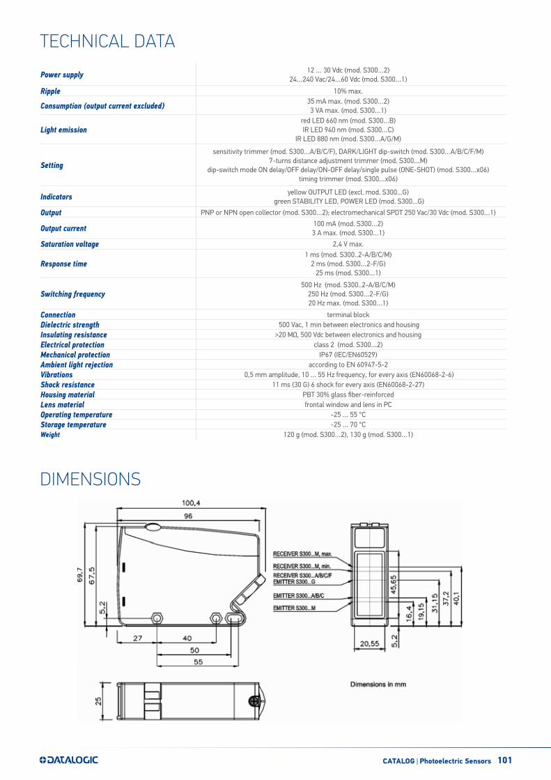
DIMENSIONS
SETTINGSS300…A and S300…B setting Position the sensor and reflector on opposite sides. Turn the sensitivity trimmer to maximum. Find the points where the yellow LED (OUT) in both vertical and horizontal positions and fix the sensor in the centre between these points. Optimum operation is obtained when both LEDs switch ON. If necessary, reduce sensitivity using the trimmer, in order to detect very small targets. In order to improve alignment, repeat the procedure detailed above whilst progressively reducing the sensitivity. S300...C setting Position the sensor and turn the sensitivity trimmer at minimum: the yellow LED is OFF (litgh mode). Place the target opposite the sensor. Turn the sensitivity trimmer clockwise until the yellow LED turns ON (Target detected state, pos.A). Remove the target, the yellow LED turns OFF. Turn the trimmer clockwise until the yellow LED turns ON (Background detected state, pos.B). The trimmer reaches maximum if the background is not detected. Turn the trimmer in intermediate position C, between the two positions A and B. The green LED must be ON. S300…F/G setting Position the sensors on opposite sides. Turn the sensitivity trimmer to maximum. Find the points where the yellow LED (OUT) is switched ON and OFF in both vertical and horizontal positions, and fix the sensor in the centre between these points. Optimum operation is obtained when both LEDs switch ON. If necessary, reduce sensitivity using the trimmer, in order to detect very small targets. In order to improve alignment, repeat the procedure detailed above whilst progressively reducing the sensitivity. S300…M setting Suppression distance setting a) Position object to detect in front of the sensor at the distance required. Turn distance adjustment
screw (ADJ) to minimum: yellow LED OFF. Rotate trimmer in a clockwise direction until the yellow LED turns ON. Object detection condition (pos.A).
b) Remove object and ensure that the background is in front of the sensor: yellow LED OFF. Rotate screw in a clockwise direction until the yellow LED turns ON: background detection condition (pos.B).
c) Rotate screw in an anti-clockwise direction until the trimmer reaches an intermediate point between position A and C. The sensor is now ready to function correctly in stable conditions.
DIAGNOSTIC FUNCTIONS
TEST+ input (only S300-PA-2-G)The TEST+ input can be used to inhibit the emitter and verify that the system is correctly operating. The TEST function is activated if the TEST+ input is connected to a voltage between 10…30V, whereas if the TEST+ input is connected to GND or it is not connected the function is disactivated. Activating the TEST the output switches from ON to OFF (in light mode), testing the total operation. The sensors are NOT safety devices, and so MUST NOT be used in the safety control of
the machines where installed.
DECLARATION OF CONFORMITY We Datalogic Automation declare under our sole responsibility that these products are conform to the 2004/108/CE and successive amendments.
WARRANTY Datalogic Automation warrants its products to be free from defects. Datalogic Automation will repair or replace, free of charge, any product found to be defective during the warranty period of 36 months from the manufacturing date. This warranty does not cover damage or liability deriving from the improper application of Datalogic Automation products.
DATALOGIC AUTOMATION Via Lavino 265 - 40050 Monte S.Pietro - Bologna – Italy Tel: +39 051 6765611 - Fax: +39 051 6759324 www.automation.datalogic.com e-mail:[email protected]
DATALOGIC AUTOMATION per l'ambiente: 100% carta riciclata. DATALOGIC AUTOMATION si riserva il diritto di apportare modifiche e/o miglioramenti senza preavviso.
© 2012–2013 Datalogic Automation - ALL RIGHTS RESERVED - Protected to the fullest extent under U.S. and international laws. • Copying, or altering of this document is prohibited without express written consent from Datalogic Automation. Datalogic and the Datalogic logo are registered trademarks of Datalogic S.p.A. in many countries, including the U.S.A. and the E.U.
826000351 Rev.C
ReceivedNot received
S300-PA SERIES INSTRUCTION MANUAL
CONTROLS
OUTPUT LED (yellow) The yellow LED ON indicates the output status. STABILITY LED (green) The green LED ON indicates that the sensor has working with a enough safety margin. POWER ON LED (green) (S300…G) The green LED indicates that the sensor is operating. SENSITIVITY TRIMMER (S300…A/B/C/F) A mono-turn trimmer adjusts the sensitivity and the sensor operating distance. The operating distance increases, rotating the screws in a clockwise direction. Do not apple more than 0.3Nm tightening torque on the trimmer screw. DISTANCE ADJUSTMENT TRIMMER (S300…M) The multi-turn trimmer has mechanical stop in clockwise turn and clutch control in anti-clockwise turn, adjusts the suppression distance through the mechanical variation of the optic triangulation angle. Please refer to “SETTINGS” paragraph for procedure indications. TIMING TRIMMER (S300…x06 exclude S300…G) Mono-turn trimmers to setting output activation and disactivation delay time. Please refer to “TIMING FUNCTIONS” paragraph for for procedure indications. Do not apple more than 0.3Nm tightening torque on the trimmer screw. DARK/LIGHT DIP-SWITCH & TIMING (S300…x06 exclude S300…G) A mono-turn trimmer to select dark/light mode (for all models) and timing (only timing versions).
WARNING: the maximum mechanical rotation range of the trimmer is 240°. Do not force over of the maximum and minimum positions.
INSTALLATION The sensor can be positioned by means of the two housing holes using two screws (M4x35 or longer, 1.2Nm maximum tightening torque). Various orientable fixing brackets to ease the sensor positioning are available (please refer to the accessories listed in the general catalogue). The operating distance is measured from the front surface of the sensor optics. For a correct use, the sensor must be installed orthogonal respect the direction of the object to detect like show in the figure. Tighten all screws surely to maintain the water-proof characteristics for IP67 (IEC/EN60529). Excessive tightening causes damage. Tighten the screws within the tightening torque range shown in the table.
TIGHTENING TORQUE (Nm)Terminal screws 0.5 max
Covers screws 0.5…0.8
CABLE CONNECTION
Use a cable of 8 … 10 mm in diameter to ensure water- and dust-proof characteristics. Two gland packings are supplied; for cables of 8 … 9 mm and 9 … 10 mm in diameter. Use a proper gland packing and a gland washer, and tighten the gland firmly (torque 10 at 15 Kgf-cm). Keep the cable insulation within 5 mm from the gland packing as shown above. Make sure the gland washer is placed in the gland packing correctly. The wires section must be in the range of 16 up to 26AWG. The stripped length must be 6mm. Make sure that the sensor is not supplied when making connections. Make correct connection to avoid product damage. When connection are made tighten the cable lock nut. Close the cover using the screw lock.
TECHNICAL DATA
S300…1-x01 / S300…1-x06 S300…2-x01 / S300…2-x06 Power supply: 24…240 VAC / 24…60 VDC 12…30 VDC Class 2 (UL508) Ripple: 10% max. 10% max. Current consumption (output current excluded): < 3VA < 35 mA
Outputs: Electromechanical SPDT 250 Vca / 30 Vcc PNP / NPN open collector
Output current: 3 A max. (resistive load) 100 mA (resistive load) Output saturation voltage: - < 2.4 V max Diagnostic function: - TEST+ input (S300…G) Response time: 25 ms 1 ms (S300…A/B/C/M); 2 ms (S300…F/G)
Switching frequency: 20Hz max 500 Hz (S300…A/B/C/M) 250 Hz (S300…F/G)
Weight: 130 g. 120 G.
Emission type: RED (660nm) S300…B ; INFRARED (940nm) S300…C INFRARED (880 nm) S300…A/G/M
Operating distance (typical values): S300…A: 0.1...15 m on R5 reflector (EG 2) / S300...B: 0.1 …10 m on R5 reflector (EG 2)
S300...C: 5 … 200 cm on 90% White target (EG 2) / S300...M: 20 … 200 cm on 90% White target S300…F/G: 0 … 50 m (EG 2)
Indicators OUTPUT LED (YELLOW) / STABILITY LED (GREEN) POWER ON LED (GREEN) S300…G
Adjustment:
Sensitivity trimmer (S300…A/B/C/F), DARK/LIGHT dip-switch (S300…A/B/C/F/M) 7-turns distance adjustment trimmer (S300…M)
Dip-switch mode ON delay / OFF delay / ON-OFF delay / Single pulse (ONE-SHOT) (S300…x06) Timig Trimmer (S300…x06 esclude S300...G)
Time Delay Range (timing vers.): 0.6…16 s (adjustment by Trimmer) Operating temperature: -25 … 55 °C Storage temperature: -25 … 70 °C Dielectric strength: : 1500 VAC, 1 min between electronics and housing Insulating resistance: > 20 M, 500 VDC between electronics and housing Ambient light rejection: according to EN 60947-5-2 Vibrations: 0.5 mm amplitude, 10 … 55 Hz frequency, for every axis (EN60068-2-6) Shock resistance: 11 ms (30 G) 6 shock for every axis (EN60068-2-27) Housing material: PBT 30% Glass fiber-reiforced Lens material: frontal window and lens in PC Mechanical protection: IP67 (IEC / EN60529)
UL requirements:
TYPE 1 ENCLOSURE. Use 60 or 75°C copper (CU) conductor and wire size No. 24-20 AWG, stranded or solid. Output Terminal tightening torque of 0.5 Nm.
VDC models: they are intended to be connected to a Class 2 transformer or class 2 power supply. VAC models: these devices shall be connected to a power-supply or system,including filters or air-gaps, of overvoltage category II
(“load level – secondary circuit of a protected utility transformer”), suitable to control over-voltages at the maximum “rated impulse withstand voltage peak of 1.2KV and with a short-circuit power limit at max 500VA.
Connections: see the “CONNECTIONS” paragraph
TIMING FUNCTIONS / TIMING DIAGRAM (S300…x06) DIP-SWITCH POSITION
LIGHT INPUT
a
OUTPUTS
OPERATIVE MODE
1 2 3 4
Normal ON OFF OFF OFF onoff
ON delay ON ON OFF OFF onoff TT
Single pulse (one-shot) ON OFF ON OFF on
offT T T
OFF delay ON OFF OFF ON onoff TT
LIGHT
TIME
ON/OFF delay ON ON OFF ON onoff
T T T
Normal OFF OFF OFF OFF onoff
ON delay OFF ON OFF OFF onoff TT
Single pulse (one-shot) OFF OFF ON OFF on
off T TT
OFF delay OFF OFF OFF ON onoff T T
DARK
TIME
ON/OFF delay OFF ON OFF ON onoff
T T T
NOTE: The timing functions are selected by dip-switches. The sensors without timing functions have only the LIGHT/DARK dip-switch and normal operative mode. The yellow LED in lighted with output ON and dark with output OFF. The delay variation is not linear with trimmer rotation in order to be more sensitive with shorter delay time. The variation is more sensitive up to half rotation (short delay), from half rotation up to end rotation the variation is faster.
CONNECTIONS S300…1-
A/B/C/F/M 01 S300…1-G S300…2-
A/B/C/F/M 01 S300…2-G
DIMENSIONS
SETTINGSS300…A and S300…B setting Position the sensor and reflector on opposite sides. Turn the sensitivity trimmer to maximum. Find the points where the yellow LED (OUT) in both vertical and horizontal positions and fix the sensor in the centre between these points. Optimum operation is obtained when both LEDs switch ON. If necessary, reduce sensitivity using the trimmer, in order to detect very small targets. In order to improve alignment, repeat the procedure detailed above whilst progressively reducing the sensitivity. S300...C setting Position the sensor and turn the sensitivity trimmer at minimum: the yellow LED is OFF (litgh mode). Place the target opposite the sensor. Turn the sensitivity trimmer clockwise until the yellow LED turns ON (Target detected state, pos.A). Remove the target, the yellow LED turns OFF. Turn the trimmer clockwise until the yellow LED turns ON (Background detected state, pos.B). The trimmer reaches maximum if the background is not detected. Turn the trimmer in intermediate position C, between the two positions A and B. The green LED must be ON. S300…F/G setting Position the sensors on opposite sides. Turn the sensitivity trimmer to maximum. Find the points where the yellow LED (OUT) is switched ON and OFF in both vertical and horizontal positions, and fix the sensor in the centre between these points. Optimum operation is obtained when both LEDs switch ON. If necessary, reduce sensitivity using the trimmer, in order to detect very small targets. In order to improve alignment, repeat the procedure detailed above whilst progressively reducing the sensitivity. S300…M setting Suppression distance setting a) Position object to detect in front of the sensor at the distance required. Turn distance adjustment
screw (ADJ) to minimum: yellow LED OFF. Rotate trimmer in a clockwise direction until the yellow LED turns ON. Object detection condition (pos.A).
b) Remove object and ensure that the background is in front of the sensor: yellow LED OFF. Rotate screw in a clockwise direction until the yellow LED turns ON: background detection condition (pos.B).
c) Rotate screw in an anti-clockwise direction until the trimmer reaches an intermediate point between position A and C. The sensor is now ready to function correctly in stable conditions.
DIAGNOSTIC FUNCTIONS
TEST+ input (only S300-PA-2-G)The TEST+ input can be used to inhibit the emitter and verify that the system is correctly operating. The TEST function is activated if the TEST+ input is connected to a voltage between 10…30V, whereas if the TEST+ input is connected to GND or it is not connected the function is disactivated. Activating the TEST the output switches from ON to OFF (in light mode), testing the total operation. The sensors are NOT safety devices, and so MUST NOT be used in the safety control of
the machines where installed.
DECLARATION OF CONFORMITY We Datalogic Automation declare under our sole responsibility that these products are conform to the 2004/108/CE and successive amendments.
WARRANTY Datalogic Automation warrants its products to be free from defects. Datalogic Automation will repair or replace, free of charge, any product found to be defective during the warranty period of 36 months from the manufacturing date. This warranty does not cover damage or liability deriving from the improper application of Datalogic Automation products.
DATALOGIC AUTOMATION Via Lavino 265 - 40050 Monte S.Pietro - Bologna – Italy Tel: +39 051 6765611 - Fax: +39 051 6759324 www.automation.datalogic.com e-mail:[email protected]
DATALOGIC AUTOMATION per l'ambiente: 100% carta riciclata. DATALOGIC AUTOMATION si riserva il diritto di apportare modifiche e/o miglioramenti senza preavviso.
© 2012–2013 Datalogic Automation - ALL RIGHTS RESERVED - Protected to the fullest extent under U.S. and international laws. • Copying, or altering of this document is prohibited without express written consent from Datalogic Automation. Datalogic and the Datalogic logo are registered trademarks of Datalogic S.p.A. in many countries, including the U.S.A. and the E.U.
826000351 Rev.C
ReceivedNot received
Power supply 12 … 30 Vdc (mod. S300…2) 24…240 Vac/24…60 Vdc (mod. S300…1)
Ripple 10% max.
Consumption (output current excluded) 35 mA max. (mod. S300…2)3 VA max. (mod. S300…1)
Light emissionred LED 660 nm (mod. S300…B)IR LED 940 nm (mod. S300…C)
IR LED 880 nm (mod. S300…A/G/M)
Setting
sensitivity trimmer (mod. S300…A/B/C/F), DARK/LIGHT dip-switch (mod. S300…A/B/C/F/M)7-turns distance adjustment trimmer (mod. S300…M)
dip-switch mode ON delay/OFF delay/ON-OFF delay/single pulse (ONE-SHOT) (mod. S300…x06)timing trimmer (mod. S300…x06)
Indicators yellow OUTPUT LED (excl. mod. S300...G) green STABILITY LED, POWER LED (mod. S300...G)
Output PNP or NPN open collector (mod. S300…2); electromechanical SPDT 250 Vac/30 Vdc (mod. S300…1)
Output current 100 mA (mod. S300…2)3 A max. (mod. S300…1)
Saturation voltage 2,4 V max.
Response time 1 ms (mod. S300..2-A/B/C/M)
2 ms (mod. S300…2-F/G)25 ms (mod. S300…1)
Switching frequency500 Hz (mod. S300..2-A/B/C/M)
250 Hz (mod. S300…2-F/G)20 Hz max. (mod. S300…1)
Connection terminal blockDielectric strength 500 Vac, 1 min between electronics and housingInsulating resistance >20 MΩ, 500 Vdc between electronics and housingElectrical protection class 2 (mod. S300…2) Mechanical protection IP67 (IEC/EN60529)Ambient light rejection according to EN 60947-5-2Vibrations 0,5 mm amplitude, 10 … 55 Hz frequency, for every axis (EN60068-2-6)Shock resistance 11 ms (30 G) 6 shock for every axis (EN60068-2-27)Housing material PBT 30% glass fiber-reinforcedLens material frontal window and lens in PCOperating temperature -25 … 55 °CStorage temperature -25 … 70 °CWeight 120 g (mod. S300…2), 130 g (mod. S300…1)
TECHNICAL DATA
DIMENSIONS

102 CATALOG | Photoelectric Sensors
S300-PA SERIES INSTRUCTION MANUAL
CONTROLS
OUTPUT LED (yellow) The yellow LED ON indicates the output status. STABILITY LED (green) The green LED ON indicates that the sensor has working with a enough safety margin. POWER ON LED (green) (S300…G) The green LED indicates that the sensor is operating. SENSITIVITY TRIMMER (S300…A/B/C/F) A mono-turn trimmer adjusts the sensitivity and the sensor operating distance. The operating distance increases, rotating the screws in a clockwise direction. Do not apple more than 0.3Nm tightening torque on the trimmer screw. DISTANCE ADJUSTMENT TRIMMER (S300…M) The multi-turn trimmer has mechanical stop in clockwise turn and clutch control in anti-clockwise turn, adjusts the suppression distance through the mechanical variation of the optic triangulation angle. Please refer to “SETTINGS” paragraph for procedure indications. TIMING TRIMMER (S300…x06 exclude S300…G) Mono-turn trimmers to setting output activation and disactivation delay time. Please refer to “TIMING FUNCTIONS” paragraph for for procedure indications. Do not apple more than 0.3Nm tightening torque on the trimmer screw. DARK/LIGHT DIP-SWITCH & TIMING (S300…x06 exclude S300…G) A mono-turn trimmer to select dark/light mode (for all models) and timing (only timing versions).
WARNING: the maximum mechanical rotation range of the trimmer is 240°. Do not force over of the maximum and minimum positions.
INSTALLATION The sensor can be positioned by means of the two housing holes using two screws (M4x35 or longer, 1.2Nm maximum tightening torque). Various orientable fixing brackets to ease the sensor positioning are available (please refer to the accessories listed in the general catalogue). The operating distance is measured from the front surface of the sensor optics. For a correct use, the sensor must be installed orthogonal respect the direction of the object to detect like show in the figure. Tighten all screws surely to maintain the water-proof characteristics for IP67 (IEC/EN60529). Excessive tightening causes damage. Tighten the screws within the tightening torque range shown in the table.
TIGHTENING TORQUE (Nm)Terminal screws 0.5 max
Covers screws 0.5…0.8
CABLE CONNECTION
Use a cable of 8 … 10 mm in diameter to ensure water- and dust-proof characteristics. Two gland packings are supplied; for cables of 8 … 9 mm and 9 … 10 mm in diameter. Use a proper gland packing and a gland washer, and tighten the gland firmly (torque 10 at 15 Kgf-cm). Keep the cable insulation within 5 mm from the gland packing as shown above. Make sure the gland washer is placed in the gland packing correctly. The wires section must be in the range of 16 up to 26AWG. The stripped length must be 6mm. Make sure that the sensor is not supplied when making connections. Make correct connection to avoid product damage. When connection are made tighten the cable lock nut. Close the cover using the screw lock.
TECHNICAL DATA
S300…1-x01 / S300…1-x06 S300…2-x01 / S300…2-x06 Power supply: 24…240 VAC / 24…60 VDC 12…30 VDC Class 2 (UL508) Ripple: 10% max. 10% max. Current consumption (output current excluded): < 3VA < 35 mA
Outputs: Electromechanical SPDT 250 Vca / 30 Vcc PNP / NPN open collector
Output current: 3 A max. (resistive load) 100 mA (resistive load) Output saturation voltage: - < 2.4 V max Diagnostic function: - TEST+ input (S300…G) Response time: 25 ms 1 ms (S300…A/B/C/M); 2 ms (S300…F/G)
Switching frequency: 20Hz max 500 Hz (S300…A/B/C/M) 250 Hz (S300…F/G)
Weight: 130 g. 120 G.
Emission type: RED (660nm) S300…B ; INFRARED (940nm) S300…C INFRARED (880 nm) S300…A/G/M
Operating distance (typical values): S300…A: 0.1...15 m on R5 reflector (EG 2) / S300...B: 0.1 …10 m on R5 reflector (EG 2)
S300...C: 5 … 200 cm on 90% White target (EG 2) / S300...M: 20 … 200 cm on 90% White target S300…F/G: 0 … 50 m (EG 2)
Indicators OUTPUT LED (YELLOW) / STABILITY LED (GREEN) POWER ON LED (GREEN) S300…G
Adjustment:
Sensitivity trimmer (S300…A/B/C/F), DARK/LIGHT dip-switch (S300…A/B/C/F/M) 7-turns distance adjustment trimmer (S300…M)
Dip-switch mode ON delay / OFF delay / ON-OFF delay / Single pulse (ONE-SHOT) (S300…x06) Timig Trimmer (S300…x06 esclude S300...G)
Time Delay Range (timing vers.): 0.6…16 s (adjustment by Trimmer) Operating temperature: -25 … 55 °C Storage temperature: -25 … 70 °C Dielectric strength: : 1500 VAC, 1 min between electronics and housing Insulating resistance: > 20 M, 500 VDC between electronics and housing Ambient light rejection: according to EN 60947-5-2 Vibrations: 0.5 mm amplitude, 10 … 55 Hz frequency, for every axis (EN60068-2-6) Shock resistance: 11 ms (30 G) 6 shock for every axis (EN60068-2-27) Housing material: PBT 30% Glass fiber-reiforced Lens material: frontal window and lens in PC Mechanical protection: IP67 (IEC / EN60529)
UL requirements:
TYPE 1 ENCLOSURE. Use 60 or 75°C copper (CU) conductor and wire size No. 24-20 AWG, stranded or solid. Output Terminal tightening torque of 0.5 Nm.
VDC models: they are intended to be connected to a Class 2 transformer or class 2 power supply. VAC models: these devices shall be connected to a power-supply or system,including filters or air-gaps, of overvoltage category II
(“load level – secondary circuit of a protected utility transformer”), suitable to control over-voltages at the maximum “rated impulse withstand voltage peak of 1.2KV and with a short-circuit power limit at max 500VA.
Connections: see the “CONNECTIONS” paragraph
TIMING FUNCTIONS / TIMING DIAGRAM (S300…x06) DIP-SWITCH POSITION
LIGHT INPUT
a
OUTPUTS
OPERATIVE MODE
1 2 3 4
Normal ON OFF OFF OFF onoff
ON delay ON ON OFF OFF onoff TT
Single pulse (one-shot) ON OFF ON OFF on
offT T T
OFF delay ON OFF OFF ON onoff TT
LIGHT
TIME
ON/OFF delay ON ON OFF ON onoff
T T T
Normal OFF OFF OFF OFF onoff
ON delay OFF ON OFF OFF onoff TT
Single pulse (one-shot) OFF OFF ON OFF on
off T TT
OFF delay OFF OFF OFF ON onoff T T
DARK
TIME
ON/OFF delay OFF ON OFF ON onoff
T T T
NOTE: The timing functions are selected by dip-switches. The sensors without timing functions have only the LIGHT/DARK dip-switch and normal operative mode. The yellow LED in lighted with output ON and dark with output OFF. The delay variation is not linear with trimmer rotation in order to be more sensitive with shorter delay time. The variation is more sensitive up to half rotation (short delay), from half rotation up to end rotation the variation is faster.
CONNECTIONS S300…1-
A/B/C/F/M 01 S300…1-G S300…2-
A/B/C/F/M 01 S300…2-G
DIMENSIONS
SETTINGSS300…A and S300…B setting Position the sensor and reflector on opposite sides. Turn the sensitivity trimmer to maximum. Find the points where the yellow LED (OUT) in both vertical and horizontal positions and fix the sensor in the centre between these points. Optimum operation is obtained when both LEDs switch ON. If necessary, reduce sensitivity using the trimmer, in order to detect very small targets. In order to improve alignment, repeat the procedure detailed above whilst progressively reducing the sensitivity. S300...C setting Position the sensor and turn the sensitivity trimmer at minimum: the yellow LED is OFF (litgh mode). Place the target opposite the sensor. Turn the sensitivity trimmer clockwise until the yellow LED turns ON (Target detected state, pos.A). Remove the target, the yellow LED turns OFF. Turn the trimmer clockwise until the yellow LED turns ON (Background detected state, pos.B). The trimmer reaches maximum if the background is not detected. Turn the trimmer in intermediate position C, between the two positions A and B. The green LED must be ON. S300…F/G setting Position the sensors on opposite sides. Turn the sensitivity trimmer to maximum. Find the points where the yellow LED (OUT) is switched ON and OFF in both vertical and horizontal positions, and fix the sensor in the centre between these points. Optimum operation is obtained when both LEDs switch ON. If necessary, reduce sensitivity using the trimmer, in order to detect very small targets. In order to improve alignment, repeat the procedure detailed above whilst progressively reducing the sensitivity. S300…M setting Suppression distance setting a) Position object to detect in front of the sensor at the distance required. Turn distance adjustment
screw (ADJ) to minimum: yellow LED OFF. Rotate trimmer in a clockwise direction until the yellow LED turns ON. Object detection condition (pos.A).
b) Remove object and ensure that the background is in front of the sensor: yellow LED OFF. Rotate screw in a clockwise direction until the yellow LED turns ON: background detection condition (pos.B).
c) Rotate screw in an anti-clockwise direction until the trimmer reaches an intermediate point between position A and C. The sensor is now ready to function correctly in stable conditions.
DIAGNOSTIC FUNCTIONS
TEST+ input (only S300-PA-2-G)The TEST+ input can be used to inhibit the emitter and verify that the system is correctly operating. The TEST function is activated if the TEST+ input is connected to a voltage between 10…30V, whereas if the TEST+ input is connected to GND or it is not connected the function is disactivated. Activating the TEST the output switches from ON to OFF (in light mode), testing the total operation. The sensors are NOT safety devices, and so MUST NOT be used in the safety control of
the machines where installed.
DECLARATION OF CONFORMITY We Datalogic Automation declare under our sole responsibility that these products are conform to the 2004/108/CE and successive amendments.
WARRANTY Datalogic Automation warrants its products to be free from defects. Datalogic Automation will repair or replace, free of charge, any product found to be defective during the warranty period of 36 months from the manufacturing date. This warranty does not cover damage or liability deriving from the improper application of Datalogic Automation products.
DATALOGIC AUTOMATION Via Lavino 265 - 40050 Monte S.Pietro - Bologna – Italy Tel: +39 051 6765611 - Fax: +39 051 6759324 www.automation.datalogic.com e-mail:[email protected]
DATALOGIC AUTOMATION per l'ambiente: 100% carta riciclata. DATALOGIC AUTOMATION si riserva il diritto di apportare modifiche e/o miglioramenti senza preavviso.
© 2012–2013 Datalogic Automation - ALL RIGHTS RESERVED - Protected to the fullest extent under U.S. and international laws. • Copying, or altering of this document is prohibited without express written consent from Datalogic Automation. Datalogic and the Datalogic logo are registered trademarks of Datalogic S.p.A. in many countries, including the U.S.A. and the E.U.
826000351 Rev.C
ReceivedNot received
CONNECTIONS
INDICATORS AND SETTINGS
Through beam emitter Through beam emitter
VAC MODELS VDC MODELS
Settings
The M model presents a multiturn adjustment screw for the adjustment of the background suppression distance using a mechanical variation of the optic triangulation angle. The other models have a mono-turn electronic trimmer that adjusts the sensitivity and the sensor operating distance. The operating distance can be increased by rotating the screws clockwise.Trimmers can be used to adjust the output activation and deactivation delay time whilst functioning mode selection is performed through DIP SWITCHES.
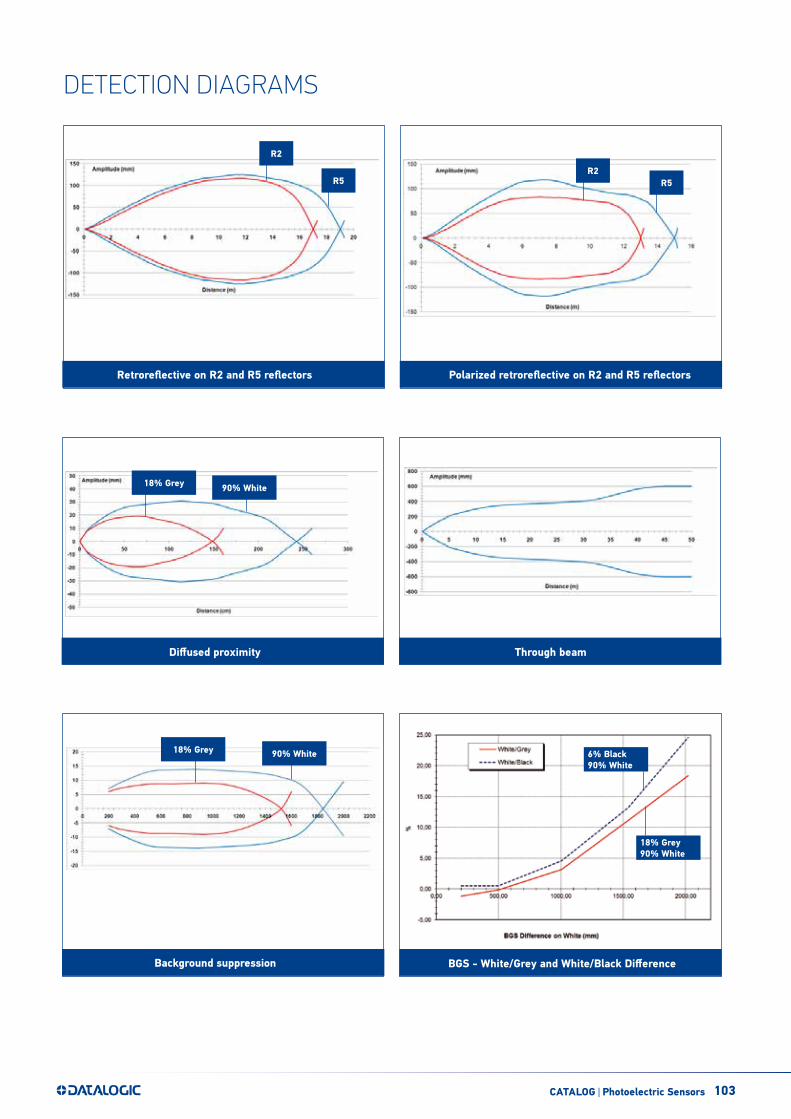
103CATALOG | Photoelectric Sensors
Retroreflective on R2 and R5 reflectors Polarized retroreflective on R2 and R5 reflectors
R5
R2
R5R2
6% Black90% White
Diffused proximity Through beam
Background suppression
18% Grey 90% White
BGS - White/Grey and White/Black Difference
18% Grey 90% White
18% Grey90% White
DETECTION DIAGRAMS

104 CATALOG | Photoelectric Sensors
MODEL SELECTION AND ORDER INFORMATION
OPTIC FUNCTION POWER SUPPLY OUTPUT SETTING MODEL ORDER No.
Retroreflective (IR LED 880 nm)
12…30 Vdc NPN/PNP
Sensitivity trimmer and D/L dip-switch S300-PA-2-A01-OC 951451500
Timing and sensitivity trimmers, D/L dip-switch S300-PA-2-A06-OC 951451510
24...240 Vac/24…60 Vdc RelaySensitivity trimmer and D/L dip-switch S300-PA-1-A01-RX 951451480
Timing and sensitivity trimmers, D/L dip-switch S300-PA-1-A06-RX 951451490
Polarized retroreflective
(red LED 660 nm)
12…30 Vdc NPN/PNP
Sensitivity trimmer and D/L dip-switch S300-PA-2-B01-OC 951451540
Timing and sensitivity trimmers, D/L dip-switch S300-PA-2-B06-OC 951451550
24...240 Vac/24…60 Vdc RelaySensitivity trimmer and D/L dip-switch S300-PA-1-B01-RX 951451520
Timing and sensitivity trimmers, D/L dip-switch S300-PA-1-B06-RX 951451530
Diffused proximity(IR LED 940 nm)
12…30 Vdc NPN/PNP
Sensitivity trimmer D/L dip-switch S300-PA-2-C01-OC 951451420
Timing and sensitivity trimmers, D/L dip-switch S300-PA-2-C06-OC 951451430
24...240 Vac/24…60 Vdc RelaySensitivity trimmer and D/L dip-switch S300-PA-1-C01-RX 951451400
Timing and sensitivity trimmers, D/L dip-switch S300-PA-1-C06-RX 951451410
Through beam receiver
12…30 Vdc NPN/PNP
Sensitivity trimmer and D/L dip-switch S300-PA-2-F01-OC 951451600
Timing and sensitivity trimmers, D/L dip-switch S300-PA-2-F06-OC 951451610
24...240 Vac/24…60 Vdc RelaySensitivity trimmer and D/L dip-switch S300-PA-1-F01-RX 951451580
Timing and sensitivity trimmers, D/L dip-switch S300-PA-1-F06-RX 951451590
Through beam emitter
(IR LED 880 nm)
12…30 Vdc-
- S300-PA-2-G00-EX 951451570
24...240 Vac/24…60 Vdc S300-PA-1-G00-EX 951451560
Background suppression
(IR LED 880 nm)
12…30 Vdc NPN/PNP
7-turns distance adjustment trimmer and /L dip-switch S300-PA-2-M01-OC 951451460
Timing and 7-turns distance adj. trimmers, D/L dip-switch S300-PA-2-M06-OC 951451470
24...240 Vac/24…60 Vdc Relay7-turns distance adjustment trimmer and D/L dip-switch S300-PA-1-M01-RX 951451440
Timing and 7-turns distance adj. trimmers, D/L dip-switch S300-PA-1-M06-RX 951451450

105
ST-511
ST-S300-PA
ACCESSORIES
MODEL DESCRIPTION ORDER No.
ST-511 mounting bracket 95ACC2810
ST-S300-PA mounting bracket 95ACC7870
DATALOGIC PRODUCT OFFERING
Stationary Industrial Scanners
Safety Light Curtains
Safety Laser Scanner
Laser Marking Systems
Mobile Computers Vision Systems
Sensors Hand Held scanners
The company endeavours to continuously improve and renew its products; for this reason the technical data and contents of this catalogue may undergo variations without prior notice. For correct installation and use, the company can guarantee only the data indicated in the instruction manual supplied with the products. Product and Company names and logos referenced may be either trademarks or registered trademarks of their respective companies. We reserve the right to make modifications and improvements.
Rev. 03, 04/2019


