

7252019 Square Hole Drilling Machine
httpslidepdfcomreaderfullsquare-hole-drilling-machine 14
Indian JSciRes1(2) 583-586 2014
1Corresponding author
SQUARE HOLE CREATED BY
SHAHRAMHOSSEINI CHALE
Producing square holes in the industry is very
complexity of manufactureUsing a drill ith
production A mathematical model for drill mech
cam is designed y using the mathematical mode
where it is not fixed and moves in a non-circular
made by drill to cam and bit Examples of non-co
was to examine the universal couplings
KEYWORDS Reuleaux Polygon Square Hole Uni
Square holes are used widely in industry Exa
applications are used in some of the couplisquare shape of the hole and shaft will
involvement of couplings accordingly prevent f
There are a variety of methods for creating squ
of these methods is making a square hole by
Using CNC machine despite the high accur
much In this method the hole plan on workpiec
CAD softwares and then after becoming t
transferred to CNC machine (Alan Overby 1
method is to use an Electrical Discharge Ma
EDM is a process that uses electrical disch
electrode to erode an electrically conductive
Fleming 2005) regardless of the mechanical p
as strength and hardness In this machiningelectrode is constructed to the shape of desire
creating electrical discharge between tool
workpiece the spark is generated and the shap
on workpiece caused (KY Song et al 2013)
noticed that no physical contact between the too
workpiece is created in the EDM method
Broaching machining method is another meth
used to create square holes on workpieces
commonly used for machining of internal or ext
profiles that are difficult to generate by ot
processes such as milling and turning Origin
was developed for non-circular internal pro
square hole and keyways (U Kokturk and ESquare hole drilling mechanism including a tri
that can have rotational motion within a squ
investigate the mathematical model for the ca
called Curves of Constant Width is propos
constant width provide a great example of ve
also allow us to gain access to a large amount
In particular Reuleaux polygons a special se
constant width give unexpected results to pract
such as drilling a square hole (Peter Fumich et
existence of non-circular curves of constant
standard Euclidean plane has been known s
ofEuler eg the Reuleaux triangle was presente
983113983123983123983118983098983090983090983093983088983085983088983089983091983096983080983119983150983148
RILLING DOWN BY USING UNIVERSA
COUPLINGS
SHTORI1a
EHSAN ZAMANIb AND AHMADR
aUniversity of Kashan bShahrekordUniversityc
Shahrekord University
ABSTRACT
common and useful and at the same time along with pr
on-coaxial couplings in addition to easier manufacturi
anism has been proposed in the first part of this paper T
l The main limitation of the square hole drilling mechan
ath There is thus a need to non-coaxial couplings in order
axial couplings are Richard Schmidt Oldham and Univers
ersal Couplings Edm Machining Curves Of Constant Width
ples of these
gs Since thelead to full
eewheeling
are holes One
NC machine
cy costs too
e designed by
o G-Code it
986) Another
chine (EDM)
rges from an
material (Ben
roperties such
method thed hole and by
electrode and
e of electrode
It should be
electrode and
d that can be
Broaching is
ernal complex
er machining
lly broaching
files such as
Budak 2004)ngle-like cam
are frame To
a discussion
d Curves of
tor space and
f information
of curves of
ical questions
al 1987) The
width in the
ince the time
d by Reuleaux
to Hornblower the inventor of
(Horst Martini and ZokhrabMustmathematical properties of the
some very important applicatio
width can be freely rotated in
contact to all four sides of the sq
be used for drilling holes
squaresReuleaux polygons are fo
non-uniform circular arcs to ea
Martini H 2000)Some Reuleau
The curves of constant width
constant width in all directionsT
vertical distance between the t
curve
Figure 1 Curves of
The square frame which the cam
body of the drillAs long as the c
whole inner surface of square
rotation inside the square fram
designed on the cam it could b
surface and do milling in a squa
transmit torque between two o
Richard Schmidt coupling (fig 2
and Universal coupling or Hook
The inventor of the coupling
Alabama said that a similar link
to some German engineers for ye
discouraged from applying
erroneously assumed that the cen
its own bearing Actually Schmi
is free to assume its own center
983148983145983150983141983081
983113983123983123983118 983098 983088983097983095983094983085983090983096983095983094 983080983120983154983145983150983156983081
NON-COAXIAL
ZA ASHRAFIc
blems such as high cost and
g also reduces the costs o
e mechanism of the drill and
ism is cam center of rotation
to transmit rotational motion
al couplings which this paper
the compound steam-engine
afaev 2008) Inrecent yearseuleaux triangle have led to
s Since a curveof constan
square always maintaining
uare a Reuleauxtriangle can
of maximum area into
rmed by connections through
ch other (Kupitz YS and
x curves are shown in fig 1
ave a plane shape with a
e proposed term width is a
o parallel lines tangent to
constant width
otates inside it is fixed to the
m is rotated 360 degrees the
frame is covered by cam
e Accordingly if a bit is
able to cover entire square
re shape Off-axis couplings
f-axis shafts For instances
) Oldham coupling (fig 3)
coupling (fig 4) are noted
ichard Schmidt of madison
rrangement had been known
rs But those engineers were
he theory because they
er disk had to be retained by
dt found that the center disk
of rotation In operation al
7252019 Square Hole Drilling Machine
httpslidepdfcomreaderfullsquare-hole-drilling-machine 24
Indian JSciRes1(2) 583-586 2014 584
three disks rotate with equal velocity (Neil Sclater and
Nicholas P Chironis 2007)
In Oldham coupling it should be noticed that it can be proved
all three disks rotate with equal rotational velocity and thus
the rotational velocity of driver shaft and driven shaft will be
equal (Yutaka Nishiyama 2009)
Figure 2 Richard Schmidt coupling
Figure 3 Oldham coupling
Figure 4 Universal coupling
A mathematical model used for cam mechanism is provided in
the first part of this paper In the second part the universal
coupling used for transmitting torque from drill to cam has
been studied
MATHEMATICAL MODEL FOR THE CAM
Equations have been derived based on the simplest curves of
constant width the circle According to fig 5 width of curve
calculated by the equation
)1(k t ht h =++ )()( π
Where h shows perpendicular line to drawn tangent to the
curve t is the angle between h line and horizontal axis and k is
a constant Family of tangents is obtained from equation
2()(sincos)( t ht yt xt y x F minus+=
Figure 5circle simplest curve of constant width
To find envelope of this family we use the equation (Andrew
David Irving 2006)
(30=part
part=
t
F F
x and y are measured in terms of the parameter t using
equations 2 and 3
(4t t ht t ht y
t t ht t ht x
cos)(sin)()(
sin)(cos)()(
prime+=
primeminus=
By choosing h(t) to different forms variety curves of constan
width equations are obtained It should be noted that h(t)
should satisfy equation 1 For example by choosing h(t)=1
equation of the simplest curves of constant width the circle is
obtainedBy choosing bt
at h += )2
3(cos)( 2
curve width
would be equal toa+2b(Andrew David Irving 2006) (Stanley
Rabinowitz 1997) If a=2 and b=8 then
(5t t t t t y
t t t t t x
cos3sin3sin)93(cos)(
sin3sin3cos)93(cos)(
minus+=
++=
The diagram of equation 5 is plotted in fig 6 using the
software maple which has shown the profile of cam curve
7252019 Square Hole Drilling Machine
httpslidepdfcomreaderfullsquare-hole-drilling-machine 34
Indian JSciRes1(2) 583-586 2014 585
Figure 6diagram of cam curve
1Universal couplings for torque transmission
In square hole drilling mechanism the cam cen
is not fixed and is displayed in a non-circular pa
a non-coaxial coupling should be used for torqu
The universal coupling is one of the most widel
coaxial couplings which has the ability to t
between parallel and non-parallel shafts and is
two universal joints The joint was used
mechanism for the first time at 1352 AD Figu
universal joint which is designed in the 16 th
maintained in Deutsches museum in munich (
Thoss et al 2006)
Figure7Initial figure of universal joint in th
According to fig 8 the relation between the r
of the driver shaft ( 1ϕ ) and the rotational angl
shafts ( 2ϕ ) obtained as equation 6
β
φ φ
cos
tantan 1
2 =
From equation 6 the velocity ratio between t
and driven shaft is calculated into equation 7
ratio diagram has also been plotted in parameter
2
11
2
)sin(sin1
cos
φ β
β
ω
ω
minus=
ter of rotation
h Due to this
transmission
y used of non-
ansmit torque
composed of
on the clock
e 7 shows the
century and is
Chr Seherr-
16th
century
tational angle
of the driven
6
e driver shaft
The velocity
1 in fig 9
7
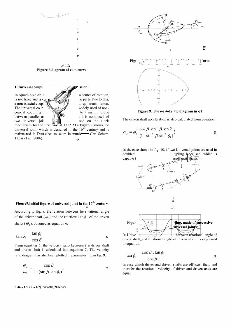
Figure 8 Universal joint a
Figure 9 The ω2 fraslω1r
The driven shaft acceleration is al
1
22
2
2
12)sinsin1(
2sinsincos
φ β
β β ω α
minus=
In the case shown in fig 10 if tw
doubled mode the Universal c
capable to transmit torque betwee
Figure 10 The universal cou
connection of two
In Universal coupling the relatio
driver shaftand rotational angle
in equation
2
11
3cos
tancostan
β
φ β φ =
In case which driver and driven
therefor the rotational velocity o
equal
gles in schematic form
tio diagram in φ1
so calculated from equation
82
1
o Universal joints are used in
upling is caused which is
n off-axis shafts
ling made of successive
niversal joints
between rotational angle of
of driven shaft is expressed
9
shafts are off-axis then and
f driver and driven axes are
7252019 Square Hole Drilling Machine
httpslidepdfcomreaderfullsquare-hole-drilling-machine 44
Indian JSciRes1(2) 583-586 2014 586
CONCLUSION
Parametric equations of cam curve are obt
follows
t t t t t y
t t t t t x
cos3sin3sin)93(cos)(
sin3sin3cos)93(cos)(
minus+=
++=
Triangular cam profile is obtained from equatcan be rotated within a square frame So if the
on the cam it can make a square hole (fiq 11)
Figure 11 The cam and the bit mount
Because the cam center of rotation is not fi
couplings are used to transmit torqueUnlike
joints which rotation velocity of driver and dri
not equal in universal couplings the drive
velocities are equal And therefor these kinds o
more appropriate to transmit torque from drill to
REFERENCES
[1]
Alan Overby 1986 Cnc machini
McGraw-Hill
[2]
Ben Fleming 2005 The EDM How To
publications
[3]
KY Song DK Chung MS Park C
ldquoDevelopment of strip EDMrdquo Procedia CIRP 6
[4]
U Kokturk E Budak 2004 ldquoOp
broaching tool designrdquo intelligent Co
Manufacturing Engineering ndash 4 Faculty of E
Natural Sciences Sabanci University Orhanli
Istanbul Turkey[5]
Peter Fumich Candice Qui
FreelanPaulSharaba Josh Orzel 1987 ldquoCurv
Width and Reuleaux Polygonsrdquo Mathemati
60(3) Jun 131-140
[6]
Horst Martini ZokhrabMustafaev 2
construction of curves of constant widthrdquo Co
Geometric Design 25(2008) 25(9) December
[7] Kupitz YS Martini H 2000 ldquoOn th
inequalities for Reuleaux polygonsrdquo J Geom
[8] Neil Sclater Nicholas P Chironis 200
and Mechanical Devices Sourcebook McGraw-
ined in t as
10
ion 10 which bit is mounted
d on it
xed universal
the universal
ven shafts are
r and driven
couplings are
cam
g handbook
ook Fleming
Chu2013
53-57
timization of
putation in
gineering and
Tuzla 34956
nn David
es of Constant
cs magazine
008 ldquoA new
mputer Aided
51-755
isoperimetric
8 171-191
Mechanisms
ill
[9]
Yutaka Nishiyama 2009
Air Conditionersrdquo Osaka Keida
77-84
[10]
Andrew David Irving 2006
amp Centre Symmetry Setsrdquo MSc
45
[11] Stanley Rabinowitz1997
Constant Widthrdquo MathPro Press
[12]
HChr Seherr-Thoss F S
Universal joints and driveshaf
Heidelberg
ldquoFrom Oldhams Coupling to
iRonshu September 60(3)
ldquoCurves of Constant Width
mini-dissertation Jun pp 1
ldquoA Polynomial Curve o
pp 23 ndash 27
hmelz E Aucktor 2006
s Springer Verlag Berlin

7252019 Square Hole Drilling Machine
httpslidepdfcomreaderfullsquare-hole-drilling-machine 24
Indian JSciRes1(2) 583-586 2014 584
three disks rotate with equal velocity (Neil Sclater and
Nicholas P Chironis 2007)
In Oldham coupling it should be noticed that it can be proved
all three disks rotate with equal rotational velocity and thus
the rotational velocity of driver shaft and driven shaft will be
equal (Yutaka Nishiyama 2009)
Figure 2 Richard Schmidt coupling
Figure 3 Oldham coupling
Figure 4 Universal coupling
A mathematical model used for cam mechanism is provided in
the first part of this paper In the second part the universal
coupling used for transmitting torque from drill to cam has
been studied
MATHEMATICAL MODEL FOR THE CAM
Equations have been derived based on the simplest curves of
constant width the circle According to fig 5 width of curve
calculated by the equation
)1(k t ht h =++ )()( π
Where h shows perpendicular line to drawn tangent to the
curve t is the angle between h line and horizontal axis and k is
a constant Family of tangents is obtained from equation
2()(sincos)( t ht yt xt y x F minus+=
Figure 5circle simplest curve of constant width
To find envelope of this family we use the equation (Andrew
David Irving 2006)
(30=part
part=
t
F F
x and y are measured in terms of the parameter t using
equations 2 and 3
(4t t ht t ht y
t t ht t ht x
cos)(sin)()(
sin)(cos)()(
prime+=
primeminus=
By choosing h(t) to different forms variety curves of constan
width equations are obtained It should be noted that h(t)
should satisfy equation 1 For example by choosing h(t)=1
equation of the simplest curves of constant width the circle is
obtainedBy choosing bt
at h += )2
3(cos)( 2
curve width
would be equal toa+2b(Andrew David Irving 2006) (Stanley
Rabinowitz 1997) If a=2 and b=8 then
(5t t t t t y
t t t t t x
cos3sin3sin)93(cos)(
sin3sin3cos)93(cos)(
minus+=
++=
The diagram of equation 5 is plotted in fig 6 using the
software maple which has shown the profile of cam curve
7252019 Square Hole Drilling Machine
httpslidepdfcomreaderfullsquare-hole-drilling-machine 34
Indian JSciRes1(2) 583-586 2014 585
Figure 6diagram of cam curve
1Universal couplings for torque transmission
In square hole drilling mechanism the cam cen
is not fixed and is displayed in a non-circular pa
a non-coaxial coupling should be used for torqu
The universal coupling is one of the most widel
coaxial couplings which has the ability to t
between parallel and non-parallel shafts and is
two universal joints The joint was used
mechanism for the first time at 1352 AD Figu
universal joint which is designed in the 16 th
maintained in Deutsches museum in munich (
Thoss et al 2006)
Figure7Initial figure of universal joint in th
According to fig 8 the relation between the r
of the driver shaft ( 1ϕ ) and the rotational angl
shafts ( 2ϕ ) obtained as equation 6
β
φ φ
cos
tantan 1
2 =
From equation 6 the velocity ratio between t
and driven shaft is calculated into equation 7
ratio diagram has also been plotted in parameter
2
11
2
)sin(sin1
cos
φ β
β
ω
ω
minus=
ter of rotation
h Due to this
transmission
y used of non-
ansmit torque
composed of
on the clock
e 7 shows the
century and is
Chr Seherr-
16th
century
tational angle
of the driven
6
e driver shaft
The velocity
1 in fig 9
7
Figure 8 Universal joint a
Figure 9 The ω2 fraslω1r
The driven shaft acceleration is al
1
22
2
2
12)sinsin1(
2sinsincos
φ β
β β ω α
minus=
In the case shown in fig 10 if tw
doubled mode the Universal c
capable to transmit torque betwee
Figure 10 The universal cou
connection of two
In Universal coupling the relatio
driver shaftand rotational angle
in equation
2
11
3cos
tancostan
β
φ β φ =
In case which driver and driven
therefor the rotational velocity o
equal
gles in schematic form
tio diagram in φ1
so calculated from equation
82
1
o Universal joints are used in
upling is caused which is
n off-axis shafts
ling made of successive
niversal joints
between rotational angle of
of driven shaft is expressed
9
shafts are off-axis then and
f driver and driven axes are
7252019 Square Hole Drilling Machine
httpslidepdfcomreaderfullsquare-hole-drilling-machine 44
Indian JSciRes1(2) 583-586 2014 586
CONCLUSION
Parametric equations of cam curve are obt
follows
t t t t t y
t t t t t x
cos3sin3sin)93(cos)(
sin3sin3cos)93(cos)(
minus+=
++=
Triangular cam profile is obtained from equatcan be rotated within a square frame So if the
on the cam it can make a square hole (fiq 11)
Figure 11 The cam and the bit mount
Because the cam center of rotation is not fi
couplings are used to transmit torqueUnlike
joints which rotation velocity of driver and dri
not equal in universal couplings the drive
velocities are equal And therefor these kinds o
more appropriate to transmit torque from drill to
REFERENCES
[1]
Alan Overby 1986 Cnc machini
McGraw-Hill
[2]
Ben Fleming 2005 The EDM How To
publications
[3]
KY Song DK Chung MS Park C
ldquoDevelopment of strip EDMrdquo Procedia CIRP 6
[4]
U Kokturk E Budak 2004 ldquoOp
broaching tool designrdquo intelligent Co
Manufacturing Engineering ndash 4 Faculty of E
Natural Sciences Sabanci University Orhanli
Istanbul Turkey[5]
Peter Fumich Candice Qui
FreelanPaulSharaba Josh Orzel 1987 ldquoCurv
Width and Reuleaux Polygonsrdquo Mathemati
60(3) Jun 131-140
[6]
Horst Martini ZokhrabMustafaev 2
construction of curves of constant widthrdquo Co
Geometric Design 25(2008) 25(9) December
[7] Kupitz YS Martini H 2000 ldquoOn th
inequalities for Reuleaux polygonsrdquo J Geom
[8] Neil Sclater Nicholas P Chironis 200
and Mechanical Devices Sourcebook McGraw-
ined in t as
10
ion 10 which bit is mounted
d on it
xed universal
the universal
ven shafts are
r and driven
couplings are
cam
g handbook
ook Fleming
Chu2013
53-57
timization of
putation in
gineering and
Tuzla 34956
nn David
es of Constant
cs magazine
008 ldquoA new
mputer Aided
51-755
isoperimetric
8 171-191
Mechanisms
ill
[9]
Yutaka Nishiyama 2009
Air Conditionersrdquo Osaka Keida
77-84
[10]
Andrew David Irving 2006
amp Centre Symmetry Setsrdquo MSc
45
[11] Stanley Rabinowitz1997
Constant Widthrdquo MathPro Press
[12]
HChr Seherr-Thoss F S
Universal joints and driveshaf
Heidelberg
ldquoFrom Oldhams Coupling to
iRonshu September 60(3)
ldquoCurves of Constant Width
mini-dissertation Jun pp 1
ldquoA Polynomial Curve o
pp 23 ndash 27
hmelz E Aucktor 2006
s Springer Verlag Berlin
7252019 Square Hole Drilling Machine
httpslidepdfcomreaderfullsquare-hole-drilling-machine 34
Indian JSciRes1(2) 583-586 2014 585
Figure 6diagram of cam curve
1Universal couplings for torque transmission
In square hole drilling mechanism the cam cen
is not fixed and is displayed in a non-circular pa
a non-coaxial coupling should be used for torqu
The universal coupling is one of the most widel
coaxial couplings which has the ability to t
between parallel and non-parallel shafts and is
two universal joints The joint was used
mechanism for the first time at 1352 AD Figu
universal joint which is designed in the 16 th
maintained in Deutsches museum in munich (
Thoss et al 2006)
Figure7Initial figure of universal joint in th
According to fig 8 the relation between the r
of the driver shaft ( 1ϕ ) and the rotational angl
shafts ( 2ϕ ) obtained as equation 6
β
φ φ
cos
tantan 1
2 =
From equation 6 the velocity ratio between t
and driven shaft is calculated into equation 7
ratio diagram has also been plotted in parameter
2
11
2
)sin(sin1
cos
φ β
β
ω
ω
minus=
ter of rotation
h Due to this
transmission
y used of non-
ansmit torque
composed of
on the clock
e 7 shows the
century and is
Chr Seherr-
16th
century
tational angle
of the driven
6
e driver shaft
The velocity
1 in fig 9
7
Figure 8 Universal joint a
Figure 9 The ω2 fraslω1r
The driven shaft acceleration is al
1
22
2
2
12)sinsin1(
2sinsincos
φ β
β β ω α
minus=
In the case shown in fig 10 if tw
doubled mode the Universal c
capable to transmit torque betwee
Figure 10 The universal cou
connection of two
In Universal coupling the relatio
driver shaftand rotational angle
in equation
2
11
3cos
tancostan
β
φ β φ =
In case which driver and driven
therefor the rotational velocity o
equal
gles in schematic form
tio diagram in φ1
so calculated from equation
82
1
o Universal joints are used in
upling is caused which is
n off-axis shafts
ling made of successive
niversal joints
between rotational angle of
of driven shaft is expressed
9
shafts are off-axis then and
f driver and driven axes are
7252019 Square Hole Drilling Machine
httpslidepdfcomreaderfullsquare-hole-drilling-machine 44
Indian JSciRes1(2) 583-586 2014 586
CONCLUSION
Parametric equations of cam curve are obt
follows
t t t t t y
t t t t t x
cos3sin3sin)93(cos)(
sin3sin3cos)93(cos)(
minus+=
++=
Triangular cam profile is obtained from equatcan be rotated within a square frame So if the
on the cam it can make a square hole (fiq 11)
Figure 11 The cam and the bit mount
Because the cam center of rotation is not fi
couplings are used to transmit torqueUnlike
joints which rotation velocity of driver and dri
not equal in universal couplings the drive
velocities are equal And therefor these kinds o
more appropriate to transmit torque from drill to
REFERENCES
[1]
Alan Overby 1986 Cnc machini
McGraw-Hill
[2]
Ben Fleming 2005 The EDM How To
publications
[3]
KY Song DK Chung MS Park C
ldquoDevelopment of strip EDMrdquo Procedia CIRP 6
[4]
U Kokturk E Budak 2004 ldquoOp
broaching tool designrdquo intelligent Co
Manufacturing Engineering ndash 4 Faculty of E
Natural Sciences Sabanci University Orhanli
Istanbul Turkey[5]
Peter Fumich Candice Qui
FreelanPaulSharaba Josh Orzel 1987 ldquoCurv
Width and Reuleaux Polygonsrdquo Mathemati
60(3) Jun 131-140
[6]
Horst Martini ZokhrabMustafaev 2
construction of curves of constant widthrdquo Co
Geometric Design 25(2008) 25(9) December
[7] Kupitz YS Martini H 2000 ldquoOn th
inequalities for Reuleaux polygonsrdquo J Geom
[8] Neil Sclater Nicholas P Chironis 200
and Mechanical Devices Sourcebook McGraw-
ined in t as
10
ion 10 which bit is mounted
d on it
xed universal
the universal
ven shafts are
r and driven
couplings are
cam
g handbook
ook Fleming
Chu2013
53-57
timization of
putation in
gineering and
Tuzla 34956
nn David
es of Constant
cs magazine
008 ldquoA new
mputer Aided
51-755
isoperimetric
8 171-191
Mechanisms
ill
[9]
Yutaka Nishiyama 2009
Air Conditionersrdquo Osaka Keida
77-84
[10]
Andrew David Irving 2006
amp Centre Symmetry Setsrdquo MSc
45
[11] Stanley Rabinowitz1997
Constant Widthrdquo MathPro Press
[12]
HChr Seherr-Thoss F S
Universal joints and driveshaf
Heidelberg
ldquoFrom Oldhams Coupling to
iRonshu September 60(3)
ldquoCurves of Constant Width
mini-dissertation Jun pp 1
ldquoA Polynomial Curve o
pp 23 ndash 27
hmelz E Aucktor 2006
s Springer Verlag Berlin


