

This project has received funding from the European Union’s Horizon 2020 research
and innovation programme under grant agreement No 731667 (MULTIDRONE)
Contributor: Prof. Ioannis Pitas
Presenter: Prof. Ioannis Pitas
Aristotle University of Thessaloniki [email protected] www.multidrone.eu
Presentation version 1.2
Stereo and Multiview imaging

This project has received funding from the European Union’s Horizon 2020 research
and innovation programme under grant agreement No 731667 (MULTIDRONE)
Introduction to Stereopsis
• The horizontal separation of the eyes
leads to a difference, stereo parallax, in
image location and appearance of an
object between the two eyes, called
stereo disparity.
• Stereo parallax is utilized by the brain in
order to extract depth information.

This project has received funding from the European Union’s Horizon 2020 research
and innovation programme under grant agreement No 731667 (MULTIDRONE)
Introduction to Stereopsis
• The two monocular views are automatically combined into a
single a single subjective view, called cyclopean view.
• With stereo vision, the viewer can see where objects are in
relation to him/herself, especially when these objects are
moving towards or away from him/her in the depth dimension
(binocular visual field).

This project has received funding from the European Union’s Horizon 2020 research
and innovation programme under grant agreement No 731667 (MULTIDRONE)
Introduction to Stereopsis
• Large binocular disparities, large depth motion and/or
frequent changes of the motion direction in depth, induce
visual discomfort.
• Binocular rivalry occurs when discrepant monocular images
are presented to the two eyes and rival for perceptual
dominance, such that only one monocular image is
perceived at a time, while the other is suppressed from
awareness.
• Binocular rivalry effects are very disturbing, when the
dominant image alternates from one eye to the other.
This project has received funding from the European Union’s Horizon 2020 research
and innovation programme under grant agreement No 731667 (MULTIDRONE)
Introduction to Stereopsis
• Binocular rivalry can be caused by differences in:
• size,
• display scene representation complexity and
• brightness.
• Due to binocular rivalry, we perceive high stereo image
quality, even if only one of the stereo images (typically the
right one) is of high quality, while the other one is of low
quality,
• This property is extensively used in asymmetric stereo video
coding.
This project has received funding from the European Union’s Horizon 2020 research
and innovation programme under grant agreement No 731667 (MULTIDRONE)
Introduction to Stereopsis
• Oculomotor depth cues:
• Accommodation: has to do with the change in ocular focus and can
be either a reflex or a consciously controlled action. The ability of
accommodation declines with age.
• Vergence: the change in ocular alignment caused by the
simultaneous movement of both eyes in opposite direction, in order
to maintain single binocular vision.
• Myosis: the eye pupil constriction to less than or equal to two
millimeters It is a normal response to an increase in illumination.

This project has received funding from the European Union’s Horizon 2020 research
and innovation programme under grant agreement No 731667 (MULTIDRONE)
Introduction to Stereopsis
• Eye convergence: the rotation of the eyes towards each
other when we try to look closer at an object (natural
movement).
• Eye divergence: the opposite phenomenon (rather unnatural
movement).

This project has received funding from the European Union’s Horizon 2020 research
and innovation programme under grant agreement No 731667 (MULTIDRONE)
Introduction to Stereopsis
• Accommodation and vergence are combined when we try to
focus on an object at a distance, offering oculomotor depth
cues.
• Accommodation and vergence conflict. When using stereo
displays, our eyes focus on the display screen, while object
disparity dictates them to converge before/after the screen.

This project has received funding from the European Union’s Horizon 2020 research
and innovation programme under grant agreement No 731667 (MULTIDRONE)
Basics of Stereopsis
• Scene depth can by inferred by simultaneous acquisition of
two scene views, from slightly different world positions.
• Use of disparity maps for depth estimation.
• Stereo camera rig:
• Parallel (two cameras with parallel optical axes).
• Converging (two cameras with converging optical axes).

This project has received funding from the European Union’s Horizon 2020 research
and innovation programme under grant agreement No 731667 (MULTIDRONE)
Basics of Stereopsis
Parallel Stereo vision
Geometry
𝑇: baseline
𝑓: focal length

This project has received funding from the European Union’s Horizon 2020 research
and innovation programme under grant agreement No 731667 (MULTIDRONE)
Basics of Stereopsis
• In a parallel stereo rig, vertical disparity/parallax is zero.
• Horizontal disparity: 𝑑 = 𝑥𝑟 – 𝑥𝑙 ≤ 0.
• 𝑑 is inversely proportional to scene depth 𝑍𝑤 (by triangle
similarity):
• Thus, 𝑑 decreases as the imaged object distance from the
camera increases.
• 𝑑 is zero for visible scene points at infinity.

This project has received funding from the European Union’s Horizon 2020 research
and innovation programme under grant agreement No 731667 (MULTIDRONE)
Basics of Stereopsis
• A dense disparity map can be estimated from detecting pixel correspondences.

This project has received funding from the European Union’s Horizon 2020 research
and innovation programme under grant agreement No 731667 (MULTIDRONE)
Epipolar Geometry
• Epipolar geometry is two-view
geometry, i.e., the geometry of
stereoscopic 3D vision.
• Property: Different 3D scene points
projecting to the same left-view 2D
point, may project to different right-
view 2D points (parallax effect).

This project has received funding from the European Union’s Horizon 2020 research
and innovation programme under grant agreement No 731667 (MULTIDRONE)
• Epipoles 𝐞𝑙, 𝐞𝑟: intersection points between camera centers
projections and image planes.
• Epipolar plane 𝜋: 3D plane containing line 𝐓 and point 𝐏.
• Epipolar lines 𝐿𝑙, 𝐿𝑟: intersection between 𝜋 and each image plane.
Epipolar Geometry

This project has received funding from the European Union’s Horizon 2020 research
and innovation programme under grant agreement No 731667 (MULTIDRONE)
• For a known 3D scene point, its left and right camera-
system 3D coordinates 𝐏𝑙 , 𝐏𝑟 are related by: 𝐏𝑟 =
𝐑 𝐏𝑙 − 𝐓 .
• By applying perspective projection:
𝐩𝑙 =𝑓𝑙𝑍𝑙𝐏𝑙 , 𝐩𝑟 =
𝑓𝑟𝑍𝑟
𝐏𝑟
• Epipolar Constraint: The image of line 𝐎𝑙𝐏 on the left-view
is the point 𝐩𝑙, but on the right-view it is the right epipolar
line L𝑟 (and vice-versa).
• Therefore, the match 𝐩𝑟 of 𝐩𝑙 must lie on L𝑟.
Epipolar Geometry

This project has received funding from the European Union’s Horizon 2020 research
and innovation programme under grant agreement No 731667 (MULTIDRONE)
• The Essential Matrix 𝐄 compactly encodes the epipolar constraint:
• 𝐄 is a 3 × 3 rank-deficient matrix. It is is completely determined by the
rotation and translation between the two cameras/views.
• If the WCS coincides with the coordinate system of the left or right camera, 𝐄
encodes extrinsic camera parameters (incl. baseline 𝐓).
The Essential Matrix 𝐄

This project has received funding from the European Union’s Horizon 2020 research
and innovation programme under grant agreement No 731667 (MULTIDRONE)
• Normalized image plane counterpart:
𝐩𝑟𝑇𝐄𝐩𝑙 = 0
• 𝐄 geometrically relates the two views.
• Using 𝐄, we can:
a. map points to their epipolar line and
b. recover extrinsic camera parameters.
The Essential Matrix 𝐄

This project has received funding from the European Union’s Horizon 2020 research
and innovation programme under grant agreement No 731667 (MULTIDRONE)
• The Fundamental Matrix 𝐅 also encodes the epipolar
constraint:
• 𝐅 is a 3 × 3 rank-deficient matrix.
• It is defined in pixel coordinates, while 𝐄 was defined in
camera plane or normalized virtual image plane coordinates.
The Fundamental Matrix 𝐅
This project has received funding from the European Union’s Horizon 2020 research
and innovation programme under grant agreement No 731667 (MULTIDRONE)
• Thus, 𝐄 only encodes extrinsic camera parameters, while 𝐅
encodes both intrinsic and extrinsic ones.
• If we estimate 𝐅 from known pixel correspondences between
views, we can obtain 𝐄 :
The Fundamental Matrix 𝐅

This project has received funding from the European Union’s Horizon 2020 research
and innovation programme under grant agreement No 731667 (MULTIDRONE)
• 𝐅 can be inferred solely by estimating pixel correspondences
(uncalibrated cameras).
• Thus, 𝐅 is useful in self-calibration (e.g., for uncalibrated 3D
scene reconstruction), i.e., in determining intrinsic camera
parameters purely from the visual content.
• Kruppa equations are related to 𝐅.
The Fundamental Matrix 𝐅

This project has received funding from the European Union’s Horizon 2020 research
and innovation programme under grant agreement No 731667 (MULTIDRONE)
• 𝐅 can be estimated by employing K > 7 left-right pixel
correspondences and the fundamental matrix constraint:
• We formulate a homogeneous system 𝐗𝐮 = 0, where 𝐗 is as
K × 9 matrix and 𝐮 contains the 9 entries of matrix 𝐅.
Eight-point Algorithm

This project has received funding from the European Union’s Horizon 2020 research
and innovation programme under grant agreement No 731667 (MULTIDRONE)
• The 𝑖 − 𝑡ℎ row of 𝐗 has the following form:
• The system can be solved using SVD decomposition:
𝐗 = 𝐔𝚺𝐕𝑇
• 𝚺 is a diagonal matrix containing the singular values. The
solution 𝐮 is the column of matrix 𝑽 corresponding to the
zero singular value of 𝚺.
• Further steps alleviate the effect of noise.
Eight-point Algorithm
This project has received funding from the European Union’s Horizon 2020 research
and innovation programme under grant agreement No 731667 (MULTIDRONE)
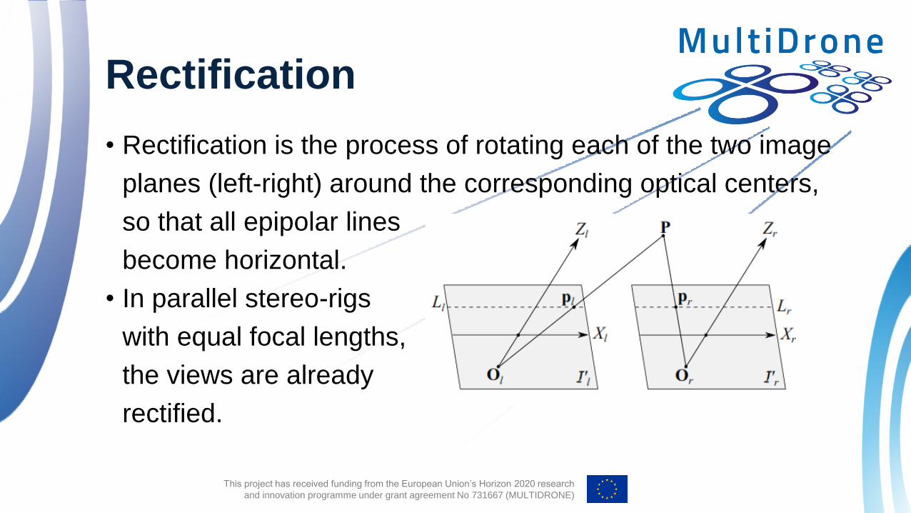
• Rectification is the process of rotating each of the two image
planes (left-right) around the corresponding optical centers,
so that all epipolar lines
become horizontal.
• In parallel stereo-rigs
with equal focal lengths,
the views are already
rectified.
Rectification
This project has received funding from the European Union’s Horizon 2020 research
and innovation programme under grant agreement No 731667 (MULTIDRONE)
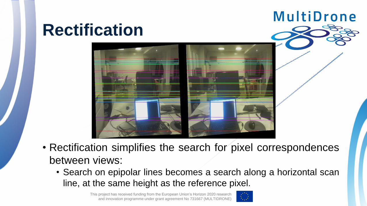
• Rectification simplifies the search for pixel correspondences
between views: • Search on epipolar lines becomes a search along a horizontal scan
line, at the same height as the reference pixel.
Rectification

This project has received funding from the European Union’s Horizon 2020 research
and innovation programme under grant agreement No 731667 (MULTIDRONE)
• Most rectification methods require a number of known point
correspondences between views, or the camera parameters.
• They define two virtual cameras with external parameters
derived from rotating the actual cameras, so that the virtual
image planes become co-planar.
• Epipolar lines become horizontal:
Rectification

This project has received funding from the European Union’s Horizon 2020 research
and innovation programme under grant agreement No 731667 (MULTIDRONE)
• 𝐑 gives the virtual camera orientation. It is an orthogonal
change-of-basis matrix.
• It can be determined row-by-row.
Rectification

This project has received funding from the European Union’s Horizon 2020 research
and innovation programme under grant agreement No 731667 (MULTIDRONE)
• The 𝑋 axis must be parallel to the baseline:
𝐑1 =𝐎𝑟 − 𝐎𝑙
𝐎𝑟 − 𝐎𝑙
• The 𝑌 axis must be orthogonal to 𝑋 and the optical axis 𝐤 of
one of the initial cameras:
𝐑2 = 𝐤 × 𝐑1
• The 𝑍 axis is orthogonal to both 𝑋 and 𝑌:
𝐑3 = 𝐑1 × 𝐑2
Rectification

This project has received funding from the European Union’s Horizon 2020 research
and innovation programme under grant agreement No 731667 (MULTIDRONE)
• The parallel, side-by-side stereo rig design tries to imitate the
way eyes are positioned on the human face
• The cameras can:
• perform horizontal shifts, thus
changing their inter-axial (baseline)
distance 𝑇,
• converge and diverge,
• change zoom and focus.
Stereo Camera Technologies
This project has received funding from the European Union’s Horizon 2020 research
and innovation programme under grant agreement No 731667 (MULTIDRONE)
• They perform well as:
• main cameras in soccer;
• other large-field sports;
• back position shots.
• When producing 3D video content, even if the two cameras
are of exactly the same model, slight differences in their
parameters will lead to discrepancies between the captured
images.
• The baseline distance cannot become arbitrarily small.
Stereo Camera Technologies

This project has received funding from the European Union’s Horizon 2020 research
and innovation programme under grant agreement No 731667 (MULTIDRONE)
• For close-up shots, the beamsplitter rig is the best choice:
• the two cameras are perpendicular
to each other,
• an appropriately positioned half sur-
face mirror splits light between them,
• the one camera shoots through the
mirror,
• the other captures the reflected light.
Stereo Camera Technologies

This project has received funding from the European Union’s Horizon 2020 research
and innovation programme under grant agreement No 731667 (MULTIDRONE)
• Main drawbacks arise from the mirror:
• even a slight mirror movement may cause serious problems;
• the rig is very fragile;
• sensitive to rapid movements and dust;
• the light sent to the vertical camera through the mirror is polarized,
due to its reflection;
• vertical camera recordings need to be flipped before synthesis with
the horizontal ones.
Stereo Camera Technologies

This project has received funding from the European Union’s Horizon 2020 research
and innovation programme under grant agreement No 731667 (MULTIDRONE)
• A different beamsplitter system, also employs mirrors, but
consists of only one mono camera with a prism attached in
front of the lens, able to split a light beam in two.
• Two, side-by-side images
of the scene are produced
on the same image frame.
Stereo Camera Technologies
This project has received funding from the European Union’s Horizon 2020 research
and innovation programme under grant agreement No 731667 (MULTIDRONE)
• Main drawbacks:
• As the two images pass through two different sides of the lens, they
undergo different distortions.
• Light scattering caused by the mirrors may result in ghosting.
• Reduced spatial image resolution.
Stereo Camera Technologies
This project has received funding from the European Union’s Horizon 2020 research
and innovation programme under grant agreement No 731667 (MULTIDRONE)
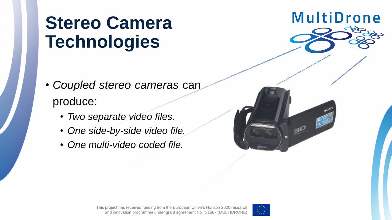
• Coupled stereo cameras can
produce:
• Two separate video files.
• One side-by-side video file.
• One multi-video coded file.
Stereo Camera Technologies

This project has received funding from the European Union’s Horizon 2020 research
and innovation programme under grant agreement No 731667 (MULTIDRONE)
• Monoscopic cameras with special mounted
stereoscopic lenses can also be used for
left and right image capturing:
• mainly used for shots with a fixed interaxial
distance,
• produce flawlessly synchronized and aligned left
and right images.
• Main drawback: The image resolution is reduced, as
smaller portion of the image sensor is used for each
stereo image channel.
Stereo Camera Technologies

This project has received funding from the European Union’s Horizon 2020 research
and innovation programme under grant agreement No 731667 (MULTIDRONE)
• The 3D geometry of a scene can be recovered, given
multiple 2D scene views.
• The multiple views may come from different view points /
cameras:
• stereoscopic / binocular view, trinocular view, Multiview
imaging
• The may come from a moving camera: Structure-from-
Motion (SfM).
• In SfM, the scene has to be static.
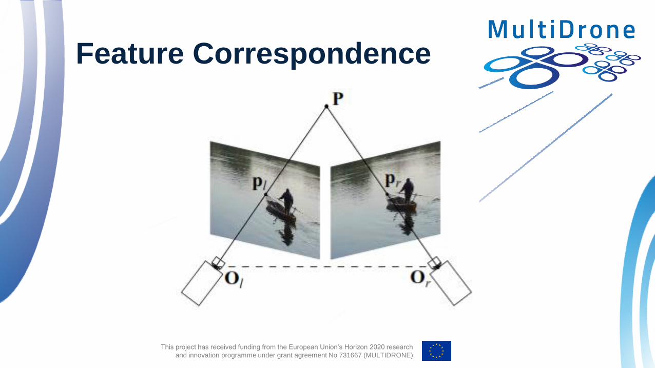
Feature Correspondence
This project has received funding from the European Union’s Horizon 2020 research
and innovation programme under grant agreement No 731667 (MULTIDRONE)
Feature Correspondence

This project has received funding from the European Union’s Horizon 2020 research
and innovation programme under grant agreement No 731667 (MULTIDRONE)
• Point correspondences have to be estimated between all
views.
• Then, if all camera parameters are known, the 3D world
location of each corresponded point can be found by
triangulation.
Feature Correspondence

This project has received funding from the European Union’s Horizon 2020 research
and innovation programme under grant agreement No 731667 (MULTIDRONE)
Feature Correspondence

This project has received funding from the European Union’s Horizon 2020 research
and innovation programme under grant agreement No 731667 (MULTIDRONE)
Feature Correspondence
This project has received funding from the European Union’s Horizon 2020 research
and innovation programme under grant agreement No 731667 (MULTIDRONE)
• 2D point correspondence
• Pixel correspondence
• Feature correspondence.
• Local feature: a small image region having interesting spatial
characteristics (e.g., corner).
• It can be described by a 𝑁-dimensional vector.
• Typically (not always), a feature detector/descriptor tries to
produce description vectors invariant to several image
transformations.
Feature Extraction

This project has received funding from the European Union’s Horizon 2020 research
and innovation programme under grant agreement No 731667 (MULTIDRONE)
• Feature detectors:
• SIFT, AGAST, SURF, Hessian Affine, CeNSuRe, BRISK, ORB,
AKAZE, or simply dense sampling.
• Feature descriptors:
• SIFT, SURF, DAISY, HOG, LIOP, LUCID, BRIEF, BRISK, FREAK,
ORB, AKAZE, LATCH, CENTRIST, BinBoost, LMoD.
Feature Extraction
This project has received funding from the European Union’s Horizon 2020 research
and innovation programme under grant agreement No 731667 (MULTIDRONE)
• Homologous image features: projections of the same natural
3D point on each camera view, after feature matching.
• Commonly used constraints for reduction of the search
space for feature correspondences:
• Epipolar constraint: when the projection geometry is known, search
for a corresponding feature point can be restricted to the epipolar
line on the other image of the stereo pair.
Feature Matching Algorithms
This project has received funding from the European Union’s Horizon 2020 research
and innovation programme under grant agreement No 731667 (MULTIDRONE)
• Uniqueness constraint: a point in one view has at most one
corresponding match in the other view.
• Continuity constraint: adjacent feature points in one view should
correspond to adjacent features in the other view.
• Topological constraint: the relative position of 3D points remains
unaltered in their projections to all views.
Feature Matching Algorithms

This project has received funding from the European Union’s Horizon 2020 research
and innovation programme under grant agreement No 731667 (MULTIDRONE)
• Area-based matching algorithms are the oldest matching
methods, used mainly for low-level feature matching.
• Matching of two feature points is based on the minimization
of some distance measure of the respective local image
windows.
Feature Matching Algorithms

This project has received funding from the European Union’s Horizon 2020 research
and innovation programme under grant agreement No 731667 (MULTIDRONE)
• Assuming feature points 𝐩𝑙 = 𝑥𝑙 , 𝑦𝑙𝑇 and 𝐩𝑟 = 𝑥𝑟 , 𝑦𝑟
𝑇 to
be matched, the grayscale intensity images 𝑓𝑙 𝑥, 𝑦 and
𝑓𝑟 𝑥, 𝑦 in a 𝐿 = 2𝑁 + 1 × 2𝑀 + 1 local neighborhood
window centered around these points are going to be
compared.
Feature Matching Algorithms

This project has received funding from the European Union’s Horizon 2020 research
and innovation programme under grant agreement No 731667 (MULTIDRONE)
• Distance-based matching measures which can be used:
• The sum of absolute differences (SAD) or 𝐿1 norm:
• The sum of squared differences (SSD) or 𝐿2 norm:
Feature Matching Algorithms

This project has received funding from the European Union’s Horizon 2020 research
and innovation programme under grant agreement No 731667 (MULTIDRONE)
• Correlation-based similarity measures which can be used:
• The normalized cross-correlation (NCC):
where:
Feature Matching Algorithms

This project has received funding from the European Union’s Horizon 2020 research
and innovation programme under grant agreement No 731667 (MULTIDRONE)
• The somewhat more stable than NCC is the modified normalized
cross-correlation (MNCC):
Feature Matching Algorithms

This project has received funding from the European Union’s Horizon 2020 research
and innovation programme under grant agreement No 731667 (MULTIDRONE)
• Other image feature characteristics which can be used for
feature matching:
• Edge attributes (e.g., edge orientation, location, intensity difference
between the two sides of the edges).
• They may suffer from occlusion problems.
• Corner attributes (e.g., coordinates):
• Harris detector.
• Orientation of line segments and coordinates of the end or/and mid
points.
• Detection methods not robust against noise.
Feature Matching Algorithms

This project has received funding from the European Union’s Horizon 2020 research
and innovation programme under grant agreement No 731667 (MULTIDRONE)
• Curve segments.
• Not frequently used because of high computational complexity and matching
ambiguities.
• Curve attributes (e.g., turning points).
• Circles.
• Ellipses.
• Polygonal regions.
Feature Matching Algorithms

This project has received funding from the European Union’s Horizon 2020 research
and innovation programme under grant agreement No 731667 (MULTIDRONE)
• Most of the feature-based stereo or multiview matching
systems use a combination of features and compare the
descriptor token vectors containing the attributes of each
feature point.
• Edges, curves, surface and region patches.
Feature Matching Algorithms

This project has received funding from the European Union’s Horizon 2020 research
and innovation programme under grant agreement No 731667 (MULTIDRONE)
• General matching approach based on a similarity metric
between a token vector pair – nearest neighbor search:
• If 𝐱, 𝐲 feature descriptor vectors and 𝐰 the weight vector of the
feature token type, then the similarity is given by:
𝑆 =1
𝐰𝑇 𝐱 − 𝐲
• ∙ can be the Euclidean distance metric and 𝐰 can be omitted if
every feature characteristic is equally important.
• We search for a pair of feature descriptors maximizing the
similarity.
Feature Matching Algorithms

This project has received funding from the European Union’s Horizon 2020 research
and innovation programme under grant agreement No 731667 (MULTIDRONE)
• Naïve nearest neighbor search: a brute force approach. • Calculate the similarity of each feature point on one image with
every other feature point on the other image and match the pair with
maximum similarity.
• Best-bin-first search: a faster but approximate method -
modification of kd-tree search.
Feature Matching Algorithms

This project has received funding from the European Union’s Horizon 2020 research
and innovation programme under grant agreement No 731667 (MULTIDRONE)
• Three general cases of 3D point cloud reconstruction:
• Calibrated cameras: known intrinsic and extrinsic parameters –
reconstruction is a simple matter of triangulation.
• Uncalibrated cameras: some or all camera parameters are
unknown – calibration needs to take place.
• Known intrinsic parameters only: estimation of the extrinsic parameters and
the 3D geometry up to an unknown scaling factor can solve the problem.
• No parameters known: 3D reconstruction only possible up to an
unknown projective transformation.
3D Reconstruction Techniques in Stereo Vision

This project has received funding from the European Union’s Horizon 2020 research
and innovation programme under grant agreement No 731667 (MULTIDRONE)
• 𝐎𝑙 , 𝐎𝑟: the centers of projection of the left/right camera –
origins of the coordinate systems 𝑋𝑙 , 𝑌𝑙 , 𝑍𝑙 , 𝑋𝑟 , 𝑌𝑟 , 𝑍𝑟 .
• , : the virtual image planes of the left/right camera.
• 𝑇𝑐: the camera baseline - distance between the two centers
of projection.
• 𝑓: the camera focal length - distance between the center of
projection of a camera and its image plane.
• 𝐎𝑐: the center of the world coordinate system 𝑋𝑤 , 𝑌𝑤 , 𝑍𝑤 -
baseline midpoint.
Parallel and Converging Camera Setups

This project has received funding from the European Union’s Horizon 2020 research
and innovation programme under grant agreement No 731667 (MULTIDRONE)
• Transformation from left/right
camera coordinates to world
coordinates in parallel stereo-
rig setup by translation by
𝑇𝑐 2 .
Parallel and Converging Camera Setups
This project has received funding from the European Union’s Horizon 2020 research
and innovation programme under grant agreement No 731667 (MULTIDRONE)
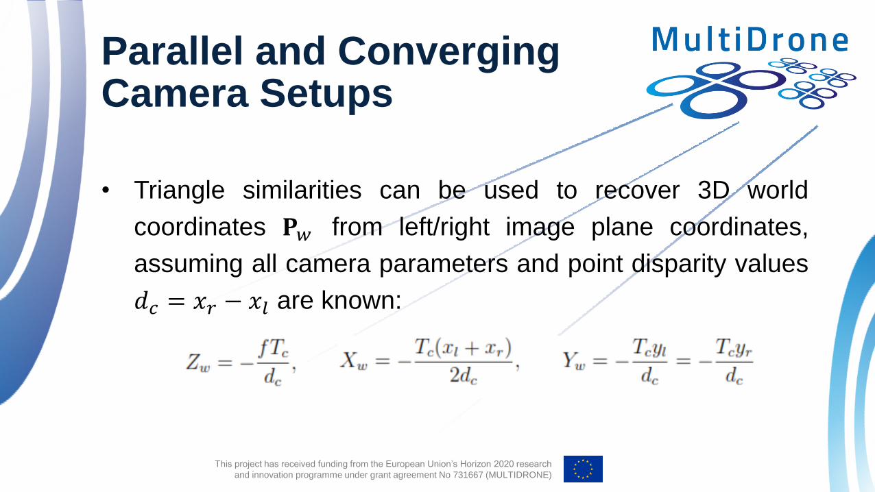
• Triangle similarities can be used to recover 3D world
coordinates 𝐏𝑤 from left/right image plane coordinates,
assuming all camera parameters and point disparity values
𝑑𝑐 = 𝑥𝑟 − 𝑥𝑙 are known:
Parallel and Converging Camera Setups

This project has received funding from the European Union’s Horizon 2020 research
and innovation programme under grant agreement No 731667 (MULTIDRONE)
• Such a camera setup produces non-positive disparity
values.
• Thus, during display, all points appear in front of the
screen.
• Points at infinity 𝑍𝑙 = 𝑍𝑟 = 𝑍𝑤 = ∞ produce zero camera
disparity and are displayed on the screen.
• The closer the 3D point is to the camera during filming, the
larger its camera disparity is (in absolute value).
Parallel and Converging Camera Setups

This project has received funding from the European Union’s Horizon 2020 research
and innovation programme under grant agreement No 731667 (MULTIDRONE)
• In the converging camera setup:
• the left/right camera optical axes form an angle 𝜃 with the
coordinate axis 𝑍𝑤 and
• converge on 𝑍𝑤 at distance 𝑍𝑐 =𝑇𝑐
2
1
tan 𝜃=
𝑇𝑐
2tan
𝜋
2− 𝜃 from the
camera centers.
• Typically, 𝜃 is small, so that sin 𝜃 ≈ 0, tan 𝜃 ≈ 0, cos 𝜃 ≈ 1.
Parallel and Converging Camera Setups

This project has received funding from the European Union’s Horizon 2020 research
and innovation programme under grant agreement No 731667 (MULTIDRONE)
• A point in world space projected on the left and right image
planes, can be transformed into the left/right camera
systems by translating first by 𝑇𝑐 2 and then rotating by an
angle −𝜃 about the 𝑌𝑤 axis:
Parallel and Converging Camera Setups

This project has received funding from the European Union’s Horizon 2020 research
and innovation programme under grant agreement No 731667 (MULTIDRONE)
• A point in left/right
image plane
coordinates can
be reverted to
world space
coordinates by:
Parallel and Converging Camera Setups
This project has received funding from the European Union’s Horizon 2020 research
and innovation programme under grant agreement No 731667 (MULTIDRONE)
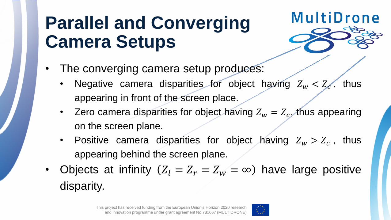
• The converging camera setup produces:
• Negative camera disparities for object having 𝑍𝑤 < 𝑍𝑐 , thus
appearing in front of the screen place.
• Zero camera disparities for object having 𝑍𝑤 = 𝑍𝑐, thus appearing
on the screen plane.
• Positive camera disparities for object having 𝑍𝑤 > 𝑍𝑐 , thus
appearing behind the screen plane.
• Objects at infinity 𝑍𝑙 = 𝑍𝑟 = 𝑍𝑤 = ∞ have large positive
disparity.
Parallel and Converging Camera Setups

This project has received funding from the European Union’s Horizon 2020 research
and innovation programme under grant agreement No 731667 (MULTIDRONE)
• Due to noise in camera
calibration, triangulation
refinement may be
needed, so that the rays
emanating from the optical
centers of the cameras
and passing through its
left and right projections
intersect on (or close to)
𝐏.
General 3D reconstruction in a calibrated stereo camera system

This project has received funding from the European Union’s Horizon 2020 research
and innovation programme under grant agreement No 731667 (MULTIDRONE)
3D reconstruction from known intrinsic camera parameters only
• 3D reconstruction is possible even without knowledge of
extrinsic camera parameters, up to an unknown scaling
factor.
• The essential matrix 𝐄 can be estimated up to an unknown scaling
factor using the eight-point algorithm, but has to be normalized.
• Then, the extrinsic parameters 𝐑,𝐓 can be recovered from 𝐄,
since 𝐄 = 𝐑𝐓×.
This project has received funding from the European Union’s Horizon 2020 research
and innovation programme under grant agreement No 731667 (MULTIDRONE)
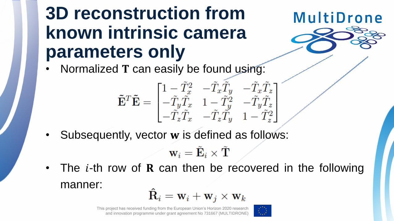
3D reconstruction from known intrinsic camera parameters only • Normalized 𝐓 can easily be found using:
• Subsequently, vector 𝐰 is defined as follows:
• The 𝑖-th row of 𝐑 can then be recovered in the following
manner:

This project has received funding from the European Union’s Horizon 2020 research
and innovation programme under grant agreement No 731667 (MULTIDRONE)
Three-Views and the Point Transfer
• Trifocal geometry: the geometry we deal with in the case of
three views.
• Trifocal tensor:
• It puts all the geometric relations between three views in a nutshell.
• It can be used to map corresponding points in two views to their
correspondences in the third view.
• It can be applied to straight lines, since the image of a line in one view can
be computed from its corresponding images in the two other views.
• It depends only on the geometric transformation parameters
between views and the intrinsic camera parameters.

This project has received funding from the European Union’s Horizon 2020 research
and innovation programme under grant agreement No 731667 (MULTIDRONE)
Three-Views and the Point Transfer
• It is uniquely defined by the camera projection matrices.
• It can be computed from image point correspondences, without
any prior information about the camera calibration parameters.
• Assuming a thee camera system:
• The trifocal plane can be defined by the three distinct optical
centers of the cameras 𝐎1, 𝐎2, 𝐎3 (general viewpoint assumption).
• 𝐅12, 𝐅13, 𝐅23 the fundamental matrices of the three possible view
pairs.
• 𝐞𝑖𝑗 , i, j = 1,2,3 the trifocal system epipoles.

This project has received funding from the European Union’s Horizon 2020 research
and innovation programme under grant agreement No 731667 (MULTIDRONE)
Three-Views and the Point Transfer
• Given two image points 𝐩1, 𝐩2 on the first and second image plane,
respectively, the exact position of the corresponding point 𝐩3 on the
third image plane can be completely specified in terms of 𝐩1, 𝐩2.

This project has received funding from the European Union’s Horizon 2020 research
and innovation programme under grant agreement No 731667 (MULTIDRONE)
Three-Views and the Point Transfer
• Point transfer or prediction of point position in the third
image plane by:
𝐩3 = 𝐅13𝐩1 × 𝐅23𝐩2.
• Considering that the three camera centers are not collinear,
the epipolar line 𝐅23𝐞31 of the epipole 𝐞31 on the second
image, is the line connecting 𝐞21 and 𝐞23:
• The epipolar line 𝐥2 = 𝐞21 × 𝐞23 will be identical to the epipolar line
𝐅23𝐞31.
• This still applies after permuting the indices 1,2,3.
This project has received funding from the European Union’s Horizon 2020 research
and innovation programme under grant agreement No 731667 (MULTIDRONE)
Three-Views and the Point Transfer
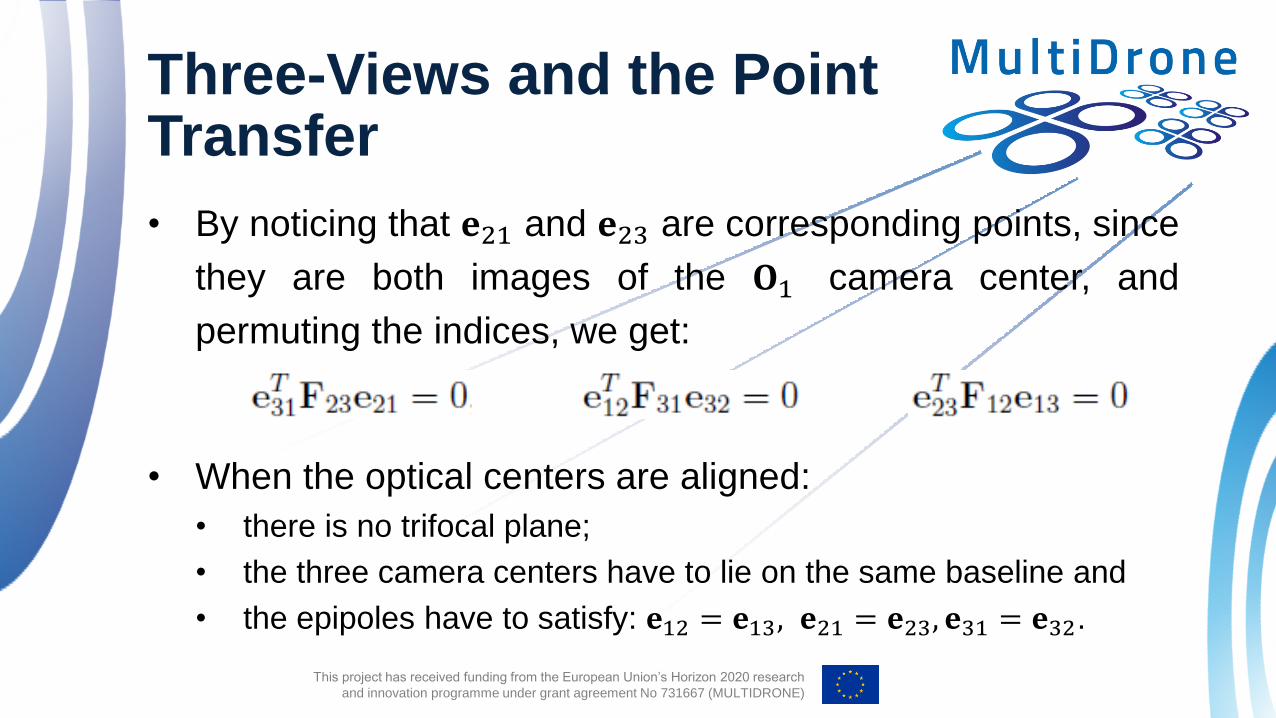
• By noticing that 𝐞21 and 𝐞23 are corresponding points, since
they are both images of the 𝐎1 camera center, and
permuting the indices, we get:
• When the optical centers are aligned:
• there is no trifocal plane;
• the three camera centers have to lie on the same baseline and
• the epipoles have to satisfy: 𝐞12 = 𝐞13, 𝐞21 = 𝐞23, 𝐞31 = 𝐞32.

This project has received funding from the European Union’s Horizon 2020 research
and innovation programme under grant agreement No 731667 (MULTIDRONE)
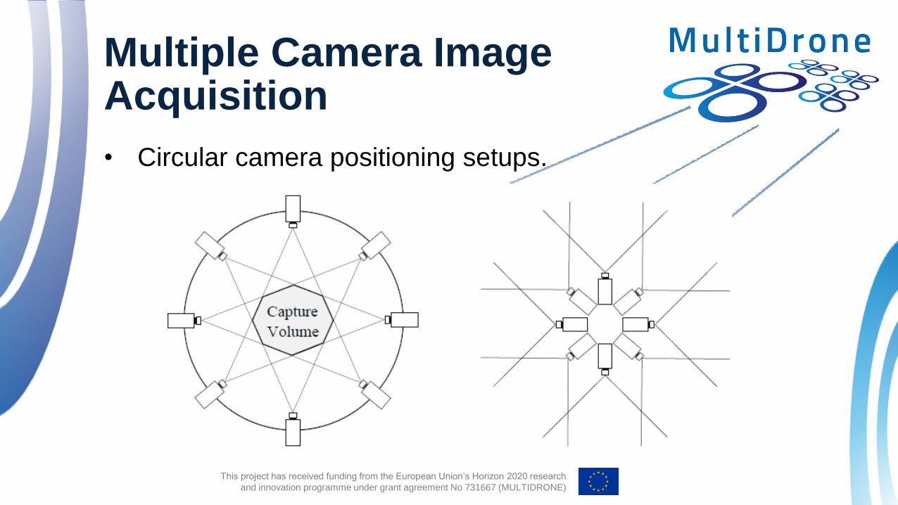
Multiple Camera Image Acquisition
• A multiple witness camera setup is usually employed,
alongside the primary production cameras, when
acquisition of complimentary 3D is desired in professional
movie shooting.
• Such systems can also be used for:
• motion capturing,
• 2D tracking, when the tracked object
is partially occluded.
This project has received funding from the European Union’s Horizon 2020 research
and innovation programme under grant agreement No 731667 (MULTIDRONE)
Multiple Camera Image Acquisition
• Circular camera positioning setups.

This project has received funding from the European Union’s Horizon 2020 research
and innovation programme under grant agreement No 731667 (MULTIDRONE)
Multiple Camera Image Acquisition
• A two-way information exchange network is established
between the cameras and the processing unit, via a parallel
connection.
• For performance reasons, the optimal assignment of the
camera units to the interconnection network nodes
requires:
• preservation of the spatial geometry of the units,
• minimization of the mutual communication/access time between
the processing unit and any camera.
This project has received funding from the European Union’s Horizon 2020 research
and innovation programme under grant agreement No 731667 (MULTIDRONE)
Coverage
• Voronoi diagrams can be used for calculating the
positioning and coverage of each camera, especially when
units are placed over a dome.
• For output image production, each pixel is reconstructed
taking into account the contribution of each camera.
• Gaussian blending is applied when merging the images
acquired by each camera, taking into account:
• the camera position and
• the pixel positions on the respective image plane.

This project has received funding from the European Union’s Horizon 2020 research
and innovation programme under grant agreement No 731667 (MULTIDRONE)
Multiple camera calibration with regard to a reference view • Other cameras are calibrated vs a reference camera.
• Most methods based on a moving planar surface with a
printed checkerboard pattern:
• Pros: not requiring a 3D calibration object.
• Cons: leading to partially calibrated cameras, since the moving
calibration grid is not visible from all views.
• Dominant plane: extrinsic camera parameters are
estimated from moving object trajectories on the basis of a
common coordinate system.
This project has received funding from the European Union’s Horizon 2020 research
and innovation programme under grant agreement No 731667 (MULTIDRONE)
Multiple camera calibration with regard to a reference view • Planar pattern: known line parallelism and information
extracted from the pattern texture are used to derive
constraints and initialize the projection matrices.
• Bright spot: a bright spot is moved throughout the 3D scene
volume, its projections in each camera are detected and a
common matrix accumulating their homogeneous image
coordinates is formed. Projective structures are refined to
Euclidean and camera projection matrices are recovered.

This project has received funding from the European Union’s Horizon 2020 research
and innovation programme under grant agreement No 731667 (MULTIDRONE)
Self-calibration
• Self-calibration or autocalibration: a family of camera
calibration methods using solely image information.
• Pros: flexibility, simplicity.
• Cons: lacking robustness, may fail in degenerate cases.
• Relies on epipolar and projective geometry concepts.
• Multiple views of a 3D scene are needed.

This project has received funding from the European Union’s Horizon 2020 research
and innovation programme under grant agreement No 731667 (MULTIDRONE)
Self-calibration
• Recent self-calibration approach: stochastic optimization of
a metric that depends on the intrinsic parameters 𝐏𝐼𝑙 , 𝐏𝐼𝑟.
• Optimization algorithms employed to this end:
• particle swarm optimization,
• genetic optimization.
• Commonly used metric for minimization:
• a reformulation of the simplified Kruppa equation.
This project has received funding from the European Union’s Horizon 2020 research
and innovation programme under grant agreement No 731667 (MULTIDRONE)
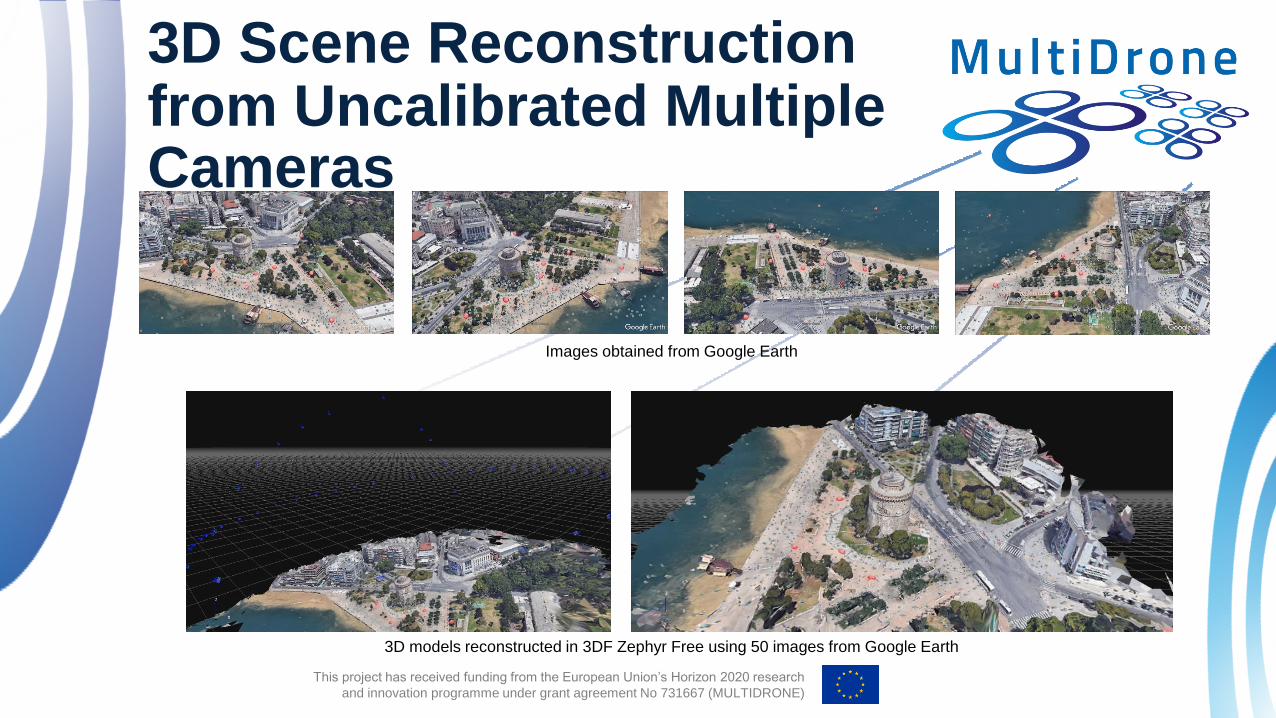
3D Scene Reconstruction from Uncalibrated Multiple Cameras
Images obtained from Google Earth
3D models reconstructed in 3DF Zephyr Free using 50 images from Google Earth

This project has received funding from the European Union’s Horizon 2020 research
and innovation programme under grant agreement No 731667 (MULTIDRONE)
Q & A
Thank you very much for your attention!
Contact: Prof. I. Pitas
www.multidrone.eu


