

Technical Report Documentation Page 1. Report No. FHWA/TX-13/0-6707-1
2. Government Accession No.
3. Recipient's Catalog No.
4. Title and Subtitle WORKER SAFETY DURING OPERATIONS WITH MOBILE ATTENUATORS
5. Report Date Published: May 2013 6. Performing Organization Code
7. Author(s) LuAnn Theiss and Roger P. Bligh
8. Performing Organization Report No. Report 0-6707-1
9. Performing Organization Name and Address Texas A&M Transportation Institute College Station, Texas 77843-3135
10. Work Unit No. (TRAIS) 11. Contract or Grant No. Project 0-6707
12. Sponsoring Agency Name and Address Texas Department of Transportation Research and Technology Implementation Office 125 E. 11th Street Austin, Texas 78701-2483
13. Type of Report and Period Covered Technical Report: September 2011–August 2012 14. Sponsoring Agency Code
15. Supplementary Notes Project performed in cooperation with the Texas Department of Transportation and the Federal Highway Administration. Project Title: Compare Trailer-Mounted Attenuators vs Truck-Mounted Attenuators Protection for Workers URL: http://tti.tamu.edu/documents/0-6707-1.pdf 16. Abstract While most transportation agencies are very familiar with truck-mounted attenuators, trailer-mounted attenuators are increasing in popularity. There is a concern for the level of protection that attenuators provide for workers when they are mounted on trailers compared to trucks. This research evaluated and compared the level of protection provided to workers by truck-mounted and trailer-mounted attenuators. No crash testing was conducted; instead, the researchers used existing crash test report data for the comparison. The researchers found that the use of heavier support vehicles for these mobile attenuators provided better protection for workers and recommend that TxDOT maintains the current policy of requiring 20,000 lb support vehicles, regardless of attenuator type. In addition, the researchers found that the concern of trailer-mounted attenuators swinging around may not be justified, given that post-impact trajectories of the impacting vehicles are similar to those reported during truck-mounted attenuator impact testing. 17. Key Words Truck-Mounted Attenuator, Trailer-Mounted Attenuator, TMA, Mobile Attenuator, Worker Safety, Work Zone
18. Distribution Statement No restrictions. This document is available to the public through NTIS: National Technical Information Service Alexandria, Virginia http://www.ntis.gov
19. Security Classif. (of this report) Unclassified
20. Security Classif. (of this page) Unclassified
21. No. of Pages 70
22. Price
Form DOT F 1700.7 (8-72) Reproduction of completed page authorized


WORKER SAFETY DURING OPERATIONS WITH MOBILE ATTENUATORS
by
LuAnn Theiss, P.E. Associate Research Engineer
Texas A&M Transportation Institute
and
Roger Bligh, P.E. Research Engineer
Texas A&M Transportation Institute
Report 0-6707-1 Project 0-6707
Project Title: Compare Trailer-Mounted Attenuators vs Truck-Mounted Attenuators Protection for Workers
Performed in cooperation with the Texas Department of Transportation
and the Federal Highway Administration
Published: May 2013
TEXAS A&M TRANSPORTATION INSTITUTE College Station, Texas 77843-3135


v
DISCLAIMER
This research was performed in cooperation with the Texas Department of Transportation
(TxDOT) and the Federal Highway Administration (FHWA). The contents of this report reflect
the views of the authors, who are responsible for the facts and the accuracy of the data presented
herein. The contents do not necessarily reflect the official view or policies of the FHWA or
TxDOT. This report does not constitute a standard, specification, or regulation.
This report is not intended for construction, bidding, or permit purposes. The engineer in
charge of the project was LuAnn Theiss, Texas P.E. #95917.
The United States Government and the State of Texas do not endorse products or
manufacturers. Trade or manufacturers’ names appear herein solely because they are considered
essential to the object of this report.

vi
ACKNOWLEDGMENTS
This project was conducted in cooperation with TxDOT and FHWA. The authors thank
Project Director Ismael Soto, Project Advisors Chris Mountain, Gary Tarter, Johnie Muller,
Randy Clawson, and Rick Swinson for their support of this research project.
vii
TABLE OF CONTENTS
Page List of Figures ............................................................................................................................. viii List of Tables ................................................................................................................................ ix Introduction ................................................................................................................................... 1
Statement of the Problem ............................................................................................................ 1 Background ................................................................................................................................. 1
History of Mobile Attenuators ................................................................................................ 1 Utility of Mobile Attenuators ..................................................................................................... 17
Physical Characteristics ............................................................................................................ 17 Maneuverability ........................................................................................................................ 19 Summary ................................................................................................................................... 20
Crashworthiness .......................................................................................................................... 21 MASH Testing .......................................................................................................................... 22 NCHRP 350 Testing ................................................................................................................. 25
Mobile Attenuator Test Parameters ...................................................................................... 25 Evaluation/Passing Criteria ................................................................................................... 29
TxDOT Testing Criteria and Evaluation................................................................................... 31 Worker Safety Assessment ......................................................................................................... 35
Collision Dynamics ................................................................................................................... 35 Comparison of Mobile Attenuator Types ................................................................................. 39 Worker Protection ..................................................................................................................... 40
Support Vehicle Occupant Ridedown Acceleration ............................................................. 41 Support Vehicle Roll-Ahead ................................................................................................. 41 Post-Impact Vehicle Trajectory ............................................................................................ 46 Flying Debris ........................................................................................................................ 49 Summary ............................................................................................................................... 50
Conclusions .................................................................................................................................. 53 Recommendations ..................................................................................................................... 53
References .................................................................................................................................... 55

viii
LIST OF FIGURES
Page Figure 1. TTI’s Texas Crash Cushion Trailer (1). ......................................................................... 2 Figure 2. Trinity Industry’s MPS 350 Truck-Mounted Attenuator (15). ....................................... 4 Figure 3. Energy Absorption’s Safe-Stop Truck-Mounted Attenuator. ........................................ 5 Figure 4. Barrier Systems’ U-MAD Truck-Mounted Attenuator (26). ......................................... 6 Figure 5. TrafFix Devices’ Scorpion Truck-Mounted Attenuator. ................................................ 7 Figure 6. Renco’s Ram 100K Truck-Mounted Attenuator (30). ................................................... 7 Figure 7. Safe-Stop Truck-Mounted Attenuator Tailgate Mount and Hydraulic Controls. ........... 9 Figure 8. TrafFix Devices’ Scorpion Trailer-Mounted Attenuator. ............................................ 10 Figure 9. Energy Absorption’s Safe-Stop Trailer-Mounted Attenuator (36). ............................. 11 Figure 10. Gregory Industries’ TTMA-100 Trailer-Mounted Attenuator. .................................. 12 Figure 11. Barrier Systems’ U-MAD Trailer-Mounted Attenuator (42). .................................... 12 Figure 12. Energy Absorption’s Vorteq Trailer-Mounted Attenuator (45). ................................ 13 Figure 13. Safe-Stop 90 in Upright Position for Transport. ........................................................ 19 Figure 14. MASH Impact Tests for Mobile Attenuators (49). .................................................... 24 Figure 15. GMC C7500 T/A Dump Truck (52). .......................................................................... 26 Figure 16. NCHRP Report 350 Impact Tests for Mobile Attenuators (50). ................................ 28 Figure 17. Sign Conventions for Measuring Roll, Pitch and Yaw (50). ...................................... 31 Figure 18. VT as a Function of MA. ............................................................................................... 38 Figure 19. VT for Various Values of MI and MS. .......................................................................... 39 Figure 20. Impacting Vehicle Occupant Safety Indicators. ......................................................... 40 Figure 21. Herbicide Truck in Corpus Christi District Fleet. ...................................................... 46 Figure 22. Post-Impact Reported Yaw Value of 97 Degrees during Test 3-52 (34). .................. 47 Figure 23. Post-Impact View of Arrow Panel on a Safe-Stop Truck-Mounted Attenuator. ....... 49 Figure 24. Post-Impact View of Arrow Panel on the TTMA-100 Trailer-Mounted
Attenuator. ............................................................................................................................ 50

ix
LIST OF TABLES
Page Table 1. Proprietary Technologies for Truck-Mounted Attenuators. ............................................ 8 Table 2. Proprietary Technologies for Trailer-Mounted Attenuators. ......................................... 14 Table 3. TxDOT-Approved Mobile Attenuators. ........................................................................ 14 Table 4. Dimensions and Masses of Mobile Attenuators. ........................................................... 17 Table 5. FHWA Acceptance Letters for Mobile Attenuators (48). ............................................. 22 Table 6. MASH Test Level 3 Impact Tests for Mobile Attenuators (49). ................................... 23 Table 7. NCHRP Report 350 Test Level 3 Impact Tests for Mobile Attenuators. ...................... 27 Table 8. TxDOT TL-3 Impact Testing Requirements per Specification 550-42-09 (53). ........... 32 Table 9. TxDOT Passing Criteria for Impact Testing.................................................................. 32 Table 10. Post Impact Speeds Calculated from 3-50 Test Data. ................................................. 36 Table 11. Post Impact Speeds Calculated from 3-51 Test Data. ................................................. 36 Table 12. Roll-Ahead Distances for Stationary Operations (55). ................................................ 42 Table 13. Roll-Ahead Distances for Mobile Operations (55). ..................................................... 42 Table 14. Calculated Values for Effective Drag Factor Based on 3-51 Test Data. ..................... 44 Table 15. Calculated Values for Roll-Ahead Based on 3-51 Test Data and Drag
Factor=0.3. ............................................................................................................................ 45 Table 16. Post-Impact Yaw of Impacting Vehicles during Angled Tests. .................................. 48


1
INTRODUCTION
STATEMENT OF THE PROBLEM
Truck-mounted attenuators (TMA) have been in use by transportation agencies for many
years. More recently, manufacturers have transferred the energy absorbing technologies of their
truck-mounted attenuators to trailer-mounted versions. Although many truck-mounted and
trailer-mounted attenuators have been accepted for use on the national highway system, their
required testing focused primarily on their structural adequacy, occupant risk for the impacting
vehicle, and post-impact vehicular response. For workers that may be located near the
attenuators when an impact occurs, the level of protection provided has not been compared. This
research compared truck-mounted and trailer-mounted attenuators in terms of worker safety.
BACKGROUND
History of Mobile Attenuators
During construction and maintenance operations, workers must often perform duties
close to active travel lanes. Although various techniques, such as channelizing devices, signs,
flaggers, and arrow panels, are used to route traffic away from work areas, these measures do not
provide positive protection for workers. For various reasons, errant vehicles may enter areas not
intended for motorists and where workers are present. The use of shadow vehicles during mobile
operations, as well as the use of barrier vehicles in stationary operations, is a common technique
for protecting workers from errant vehicles. While this protection provides a benefit for workers,
it does not protect occupants in errant vehicles that may strike the shadow vehicle. This led to
the development of several impact attenuation devices that were designed to decrease the
severity of collisions with the shadow vehicle by errant vehicles. These devices were essentially
compact crash cushions attached to the rear of the shadow vehicles and were intended to reduce
the accelerations felt by occupants of the errant vehicle. When shadow vehicles and barrier
vehicles are used with mobile attenuators, they are referred to as support vehicles.
Early Product Development
In the early 1970s, researchers at the Texas Transportation Institute (TTI) successfully
developed and crash tested the first trailer-mounted attenuator and called it the “Texas Crash
2
Cushion Trailer.” This trailer, shown in Figure 1, consisted of several 20-gage 55-gallon steel
drums with 8 inch holes in the top and bottom and mounted on a set of wheels and a trailer hitch.
The trailer was described as a “workable and easily used implement for the protection of
personnel and equipment” during maintenance activities. This device was never commercially
available as an assembled unit. However, based on successful crash testing, TxDOT used it
extensively in the field. But due to its size, the trailer proved difficult to handle in the field in
many situations. With a desire to improve the device, TxDOT eliminated the trailer and attached
the drum array directly to the rear of the shadow vehicle using a cantilever-type connection.
Although it was never crash-tested, this was probably the first truck-mounted attenuator (1, 2).
Figure 1. TTI’s Texas Crash Cushion Trailer (1).
In the mid-1970s and early 1980s, other mobile attenuators were developed. Connecticut
Department of Transportation, working in conjunction with the University of Connecticut,
developed a truck-mounted attenuator that employed steel cylinders approximately 2 ft in
diameter enclosed within a telescoping box-beam frame. This device evolved over time and is
still in use today in Connecticut on roadways with posted speed limits of 45 mph or less. The
design was not proprietary in nature, and interested agencies may obtain complete sets of
fabrication drawings and specifications for the current design (3, 4).
Energy Absorption Systems, Inc. (EASI) played a role in early development of several
different truck-mounted attenuator systems. EASI, working in conjunction with California
Department of Transportation (CalTrans), developed a mobile attenuator system that used
vermiculite concrete, which is a lightweight concrete that has a cushioning effect (5). EASI also
3
worked with Hexcel Corporation to develop two other attenuator systems. The first system
consisted of polyurethane foam-filled cardboard honeycomb cells (called Hex-Foam) and was
introduced in 1981. A second system consisted of formed aluminum sheet metal cartridges and
honeycomb cells combined to form the Alpha 1000 mobile attenuator. The Alpha 1000 was
introduced in 1986 and was the first truck-mounted attenuator to feature a 90-degree vertical
pivot, which allowed the operator to stow the attenuator in an upright position for transport,
significantly improving the maneuverability of the support vehicle (2). Although routine use of
truck-mounted attenuators was not common practice during this time period, the Alpha 1000 was
commercially available until the manufacturer recently discontinued the product.
Most of these early mobile attenuators were designed for and tested at moderate impact
speeds of 45 mph or less (6, 7, 8, 9, 10). The use of higher impact speeds and heavier impacting
vehicles could easily produce attenuators that were too large and impractical to use. As impact
attenuating technologies evolved, higher impact speeds were introduced into the development of
more compact products.
In 1989, TxDOT contracted with the TTI to develop a set of performance specifications
for truck-mounted attenuators. The project was aimed at assessing the performance of several
truck-mounted attenuators and developing the criteria for an acceptable product. The
information was used by TxDOT’s purchasing personnel to establish minimum performance
requirements for devices purchased by the agency (11).
Evolving Technologies
In the mid- and late-1990s, several new mobile attenuators were designed and tested at
speeds above 60 mph. Attenuators are developed using specific technologies that are patented
and considered proprietary. Several of these designs were further refined over time to create the
products that are commonly used today.
The MPS 350 truck-mounted attenuator, shown in Figure 2, was developed by Syro Steel,
Inc. in the mid-1990s. The MPS 350 frame consists of steel C-channel beams, which are
connected by an impact face at the rear and cross braces along the length of the frame. The
channels have steel face plates across the opening, which creates a box-shaped section. When
struck, the rear portion of the frame slides into a cutter assembly, which then shears off the metal

4
plates. This shearing action dissipates the energy of the impacting vehicle. This attenuator was
originally accepted for use in June 1996, but design modifications were made later that year in
order to accommodate higher impact speeds. By 2003, Trinity Industries, Inc. purchased Syro
Steel, Inc. and further modified the MPS 350 by widening the steel frame impact face and
strengthening the attachment between the cutter assemblies and the structural supports that keep
the device level (12, 13, 14).
Figure 2. Trinity Industry’s MPS 350 Truck-Mounted Attenuator (15).
The Safe-Stop truck-mounted attenuator, shown in Figure 3, was also developed in the
late 1990s by EASI and consists of two different light-weight aluminum cartridges contained in a
steel support frame. When struck, the frame collapses and the energy absorbing aluminum
cartridges absorb the energy from the impacting vehicle. The cartridges are replaceable, and the
frame may be reusable after impact. A unique feature of this attenuator is the bi-folding
articulating nature of the steel support frame, which allows one cartridge to be stowed above the
other for transport. This attenuator was originally accepted for use in April 1999, although
several design modifications were made by 2005, including changing the release hardware,
adding metal guides for the cartridges, adding corner gussets to restrict some rotation, and
lengthening some frame arms for improved collapse geometry. In 2006, the design of the
tailgate mount was modified, but the general design of the attenuator remained unchanged (16,
17, 18, 19, 20, 21).

5
Figure 3. Energy Absorption’s Safe-Stop Truck-Mounted Attenuator.
The U-MAD truck-mounted attenuator, shown in Figure 4 was developed by Albert W.
Unrath, Sr. in the late 1990s. The U-MAD truck-mounted attenuator consists of an aluminum
box containing eight separate internal compartments filled with variable density energy
dissipating material. The top back surface of the aluminum box was slightly tapered. The
proprietary material enclosed in the box absorbs the energy from the impacting vehicle. This
attenuator also has a lift mechanism, which allows the attenuator to be raised into a vertical
position for transport. This attenuator was originally accepted for use in March 2000. By 2006,
the ownership rights were transferred to Impact Absorption, who eliminated the taper on the
aluminum box, making a fully rectangular enclosure. Ownership rights for the U-MAD truck-
mounted attenuator now belong to Barrier Systems, Inc. (22, 23, 24, 25).
6
Figure 4. Barrier Systems’ U-MAD Truck-Mounted Attenuator (26).
The Scorpion truck-mounted attenuator, shown in Figure 5 was developed by TrafFix
Devices, Inc. in the late 1990s. The Scorpion truck-mounted attenuator consists of a curved
aluminum tube framework and engineered aluminum cartridge cushioning technology. Crash
energy is absorbed by both the aluminum frames and the proprietary energy absorbing contents
of the cartridges. The curved design is intended to redirect side angle impacts away from the
exposed corner of the truck. This attenuator also has a lift mechanism, which allows the
attenuator to be raised into two different vertical positions for transport. This attenuator was
originally accepted for use in July 2000 (27, 28).
7
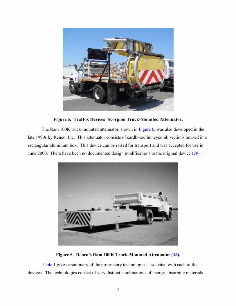
Figure 5. TrafFix Devices’ Scorpion Truck-Mounted Attenuator.
The Ram 100K truck-mounted attenuator, shown in Figure 6, was also developed in the
late 1990s by Renco, Inc. This attenuator consists of cardboard honeycomb sections housed in a
rectangular aluminum box. This device can be raised for transport and was accepted for use in
June 2000. There have been no documented design modifications to the original device (29).
Figure 6. Renco’s Ram 100K Truck-Mounted Attenuator (30).
Table 1 gives a summary of the proprietary technologies associated with each of the
devices. The technologies consist of very distinct combinations of energy-absorbing materials.
8
These materials are designed to lower the deceleration rate for the occupants of the impacting
vehicle when the vehicle strikes the attenuator. This is their primary purpose in the attenuator
design.
Table 1. Proprietary Technologies for Truck-Mounted Attenuators. Attenuator Proprietary Energy-Absorbing Technology
Alpha 100K Cartridge of energy absorbing lightweight aluminum sheet metal of various thicknesses
MPS 350 III Steel C-channel beams connected by an impact face and a series of steel cross-braces, which are torn apart by a cutter assembly upon impact
SAFE-STOP 180 Two types of lightweight aluminum energy absorbing cartridges on a bi-folding articulated steel frame assembly
U-MAD Cushion 100K Aluminum box containing eight separate internal compartments filled with variable density energy-dissipating material
Scorpion C10000 Three aluminum boxes with energy absorbing aluminum honeycomb supported by curved tubular aluminum frames
Ram 100K Cardboard honeycomb sections housed in a rectangular aluminum box
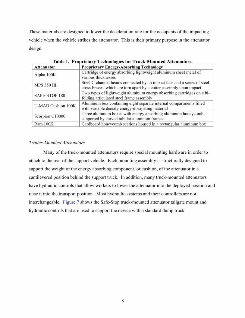
Trailer-Mounted Attenuators
Many of the truck-mounted attenuators require special mounting hardware in order to
attach to the rear of the support vehicle. Each mounting assembly is structurally designed to
support the weight of the energy absorbing component, or cushion, of the attenuator in a
cantilevered position behind the support truck. In addition, many truck-mounted attenuators
have hydraulic controls that allow workers to lower the attenuator into the deployed position and
raise it into the transport position. Most hydraulic systems and their controllers are not
interchangeable. Figure 7 shows the Safe-Stop truck-mounted attenuator tailgate mount and
hydraulic controls that are used to support the device with a standard dump truck.
9
Figure 7. Safe-Stop Truck-Mounted Attenuator Tailgate Mount and Hydraulic Controls.
In the late 1990s and early 2000s, several manufacturers designed trailer-mounted
versions of their existing truck-mounted attenuators. In most cases, special mounting hardware
was no longer needed because the trailer axle provided support for the cushion. The trailer-
mounted attenuators were connected to the rear of the support vehicle by way of a simple pintle
hook and could be towed just like a normal trailer. Since most trailer-mounted attenuators do not
need to be raised for transport, hydraulic lift controls were not needed. While several trailer-
mounted attenuators were simply modified truck-mounted attenuator designs, others were
originally developed as trailers and entered the market during this same time period.
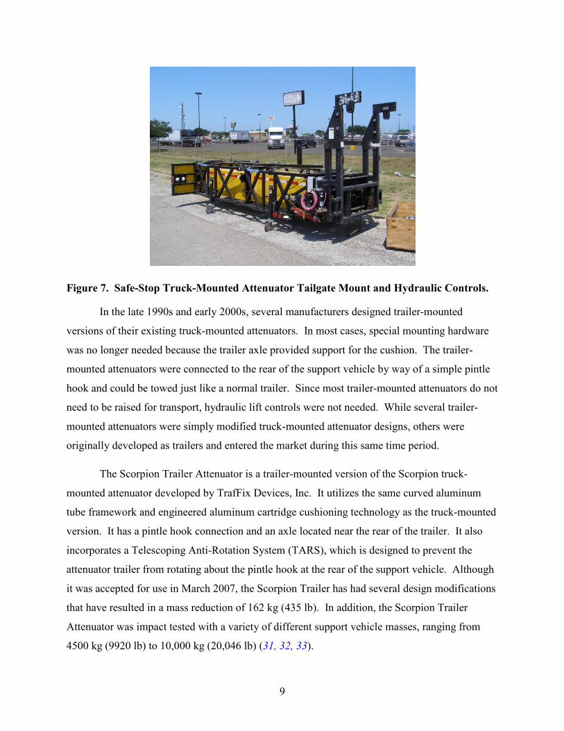
The Scorpion Trailer Attenuator is a trailer-mounted version of the Scorpion truck-
mounted attenuator developed by TrafFix Devices, Inc. It utilizes the same curved aluminum
tube framework and engineered aluminum cartridge cushioning technology as the truck-mounted
version. It has a pintle hook connection and an axle located near the rear of the trailer. It also
incorporates a Telescoping Anti-Rotation System (TARS), which is designed to prevent the
attenuator trailer from rotating about the pintle hook at the rear of the support vehicle. Although
it was accepted for use in March 2007, the Scorpion Trailer has had several design modifications
that have resulted in a mass reduction of 162 kg (435 lb). In addition, the Scorpion Trailer
Attenuator was impact tested with a variety of different support vehicle masses, ranging from
4500 kg (9920 lb) to 10,000 kg (20,046 lb) (31, 32, 33).
10
Figure 8. TrafFix Devices’ Scorpion Trailer-Mounted Attenuator.
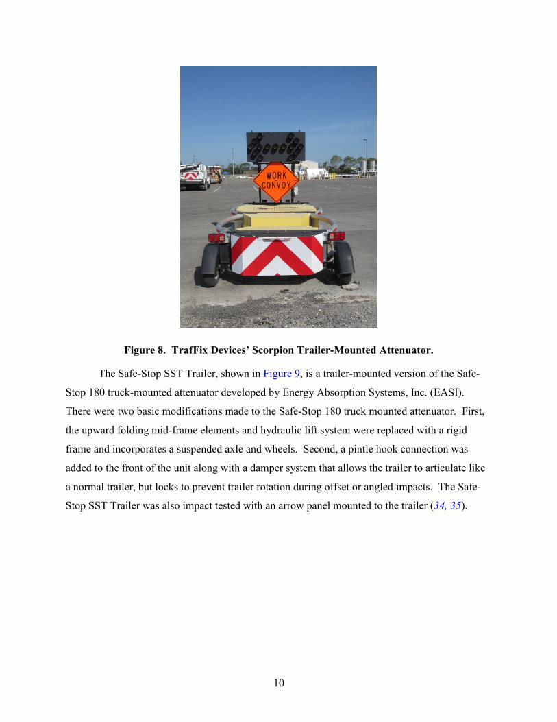
The Safe-Stop SST Trailer, shown in Figure 9, is a trailer-mounted version of the Safe-
Stop 180 truck-mounted attenuator developed by Energy Absorption Systems, Inc. (EASI).
There were two basic modifications made to the Safe-Stop 180 truck mounted attenuator. First,
the upward folding mid-frame elements and hydraulic lift system were replaced with a rigid
frame and incorporates a suspended axle and wheels. Second, a pintle hook connection was
added to the front of the unit along with a damper system that allows the trailer to articulate like
a normal trailer, but locks to prevent trailer rotation during offset or angled impacts. The Safe-
Stop SST Trailer was also impact tested with an arrow panel mounted to the trailer (34, 35).

11
Figure 9. Energy Absorption’s Safe-Stop Trailer-Mounted Attenuator (36).
The TTMA-100 trailer-mounted attenuator, shown in Figure 10, was developed by Safety
by Design Company. It was a new design that was not based on a prior truck-mounted style
attenuator. This design was based on a bursting tube technology originally developed for the
energy-absorbing box-beam guardrail. Energy from the impact is absorbed when the inner
square tubing is forced into the outer tubing, splitting the corners of the outer tubing. The
TTMA-100 was modified and the new design was accepted by FHWA in July 2011. Ownership
rights were transferred first to Safety Trailers, Inc. and are now owned by Gregory Industries,
Inc. (37, 38, 39).
12
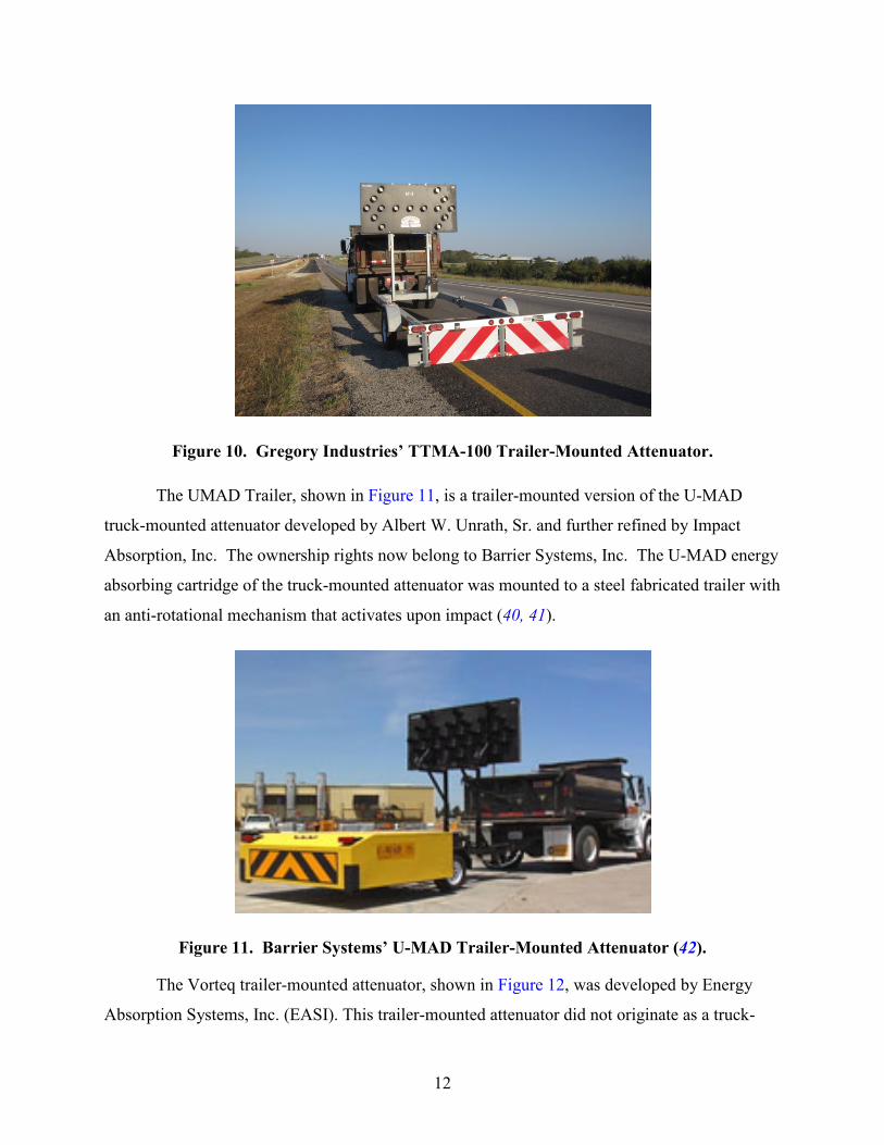
Figure 10. Gregory Industries’ TTMA-100 Trailer-Mounted Attenuator.
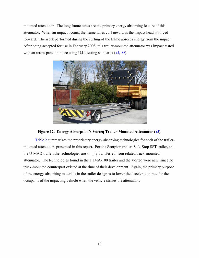
The UMAD Trailer, shown in Figure 11, is a trailer-mounted version of the U-MAD
truck-mounted attenuator developed by Albert W. Unrath, Sr. and further refined by Impact
Absorption, Inc. The ownership rights now belong to Barrier Systems, Inc. The U-MAD energy
absorbing cartridge of the truck-mounted attenuator was mounted to a steel fabricated trailer with
an anti-rotational mechanism that activates upon impact (40, 41).
Figure 11. Barrier Systems’ U-MAD Trailer-Mounted Attenuator (42).
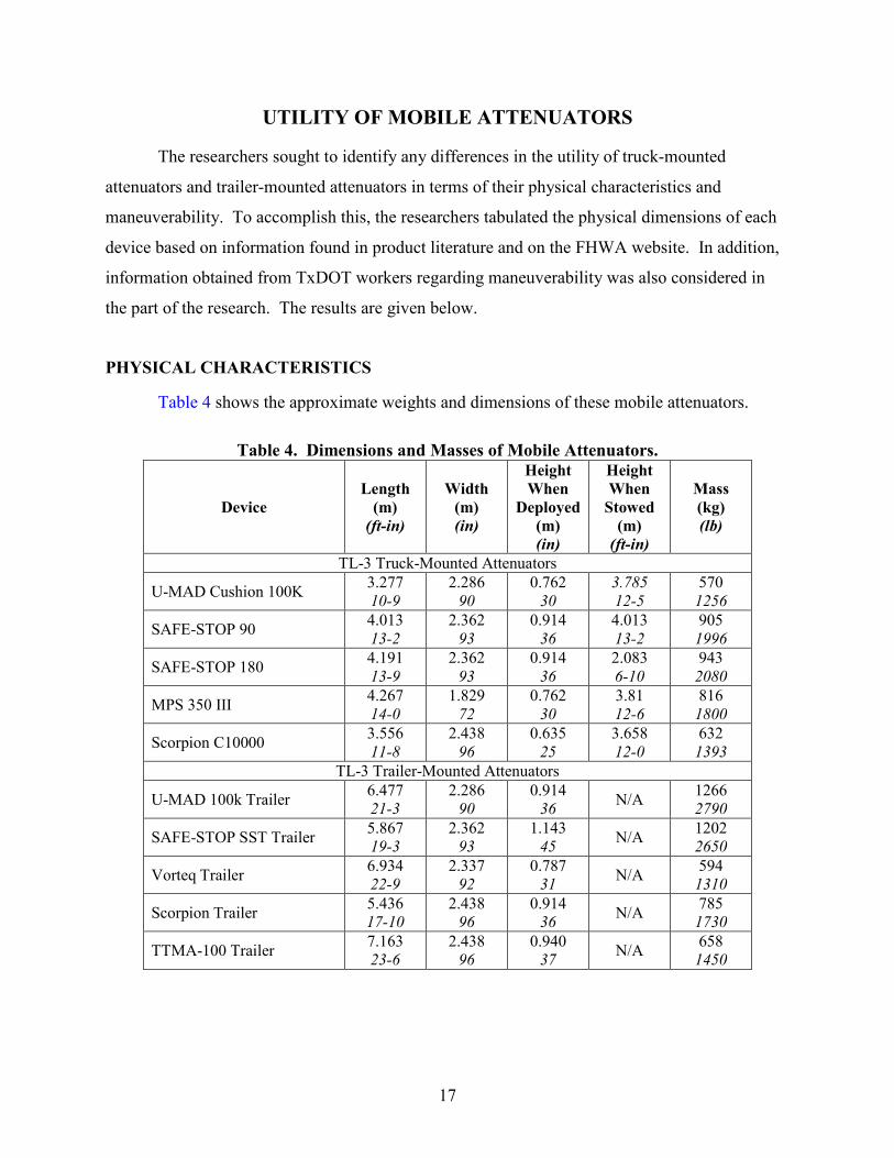
The Vorteq trailer-mounted attenuator, shown in Figure 12, was developed by Energy
Absorption Systems, Inc. (EASI). This trailer-mounted attenuator did not originate as a truck-
13
mounted attenuator. The long frame tubes are the primary energy absorbing feature of this
attenuator. When an impact occurs, the frame tubes curl inward as the impact head is forced
forward. The work performed during the curling of the frame absorbs energy from the impact.
After being accepted for use in February 2008, this trailer-mounted attenuator was impact tested
with an arrow panel in place using U.K. testing standards (43, 44).
Figure 12. Energy Absorption’s Vorteq Trailer-Mounted Attenuator (45).
Table 2 summarizes the proprietary energy absorbing technologies for each of the trailer-
mounted attenuators presented in this report. For the Scorpion trailer, Safe-Stop SST trailer, and
the U-MAD trailer, the technologies are simply transferred from related truck-mounted
attenuator. The technologies found in the TTMA-100 trailer and the Vorteq were new, since no
truck-mounted counterpart existed at the time of their development. Again, the primary purpose
of the energy-absorbing materials in the trailer design is to lower the deceleration rate for the
occupants of the impacting vehicle when the vehicle strikes the attenuator.

14
Table 2. Proprietary Technologies for Trailer-Mounted Attenuators. Attenuator Proprietary Energy-Absorbing Technology
Scorpion Trailer Trailer-mounted version of Scorpion C10000 TMA with anti-rotational feature on the steel trailer tongue
SAFE-STOP SST Trailer-mounted version of SAFE-STOP 180 TMA with locking anti-rotational dampeners
TTMA-100 Trailer Bursting tube technology assembly (similar to a box-beam guardrail) mounted on a tubular steel frame
U-MAD 100k Trailer Trailer-mounted version of U-MAD Cushion 100K with anti-rotational feature.
Vorteq Trailer Steel frame tubes that curl upon impact
Devices Approved by Texas Department of Transportation
TxDOT’s Compliant Work Zone Traffic Control Devices List (46) contains products that
have been evaluated and determined to be acceptable traffic control devices for use in work
zones on TxDOT roadways. These devices are shown in Table 3. Test Level 3 (TL-3) devices
are approved for use on all TxDOT roadways, while Test Level 2 (TL-2) devices are approved
only for use on roadways with regulatory speed limits of 45 mph or less. Within each device
category, the devices are listed in alphabetical order by manufacturer of record.
Table 3. TxDOT-Approved Mobile Attenuators. Test Level
Type of Mount Device Manufacturer of Record
3
Truck
U-MAD Cushion 100K Barrier Systems, Inc. Alpha 100K Energy Absorption Systems, Inc. SAFE-STOP Energy Absorption Systems, Inc. SAFE-STOP 180 Energy Absorption Systems, Inc. Ram 100K Renco Supply, Inc. MPS 350 III Trinity Highway Products, LLC Scorpion C10000 TrafFix Devices, Inc.
Trailer
U-MAD 100k Barrier Systems, Inc SAFE-STOP SST Energy Absorption Systems, Inc. Vorteq Energy Absorption Systems, Inc. Scorpion TrafFix Devices, Inc. TTMA-100 Safety Trailers
2 Truck Alpha 70K Energy Absorption Systems, Inc. Ren-Gard 815 Renco Supply, Inc. Scorpion A 10000 TrafFix Devices, Inc.
Trailer U-MAD 70k Barrier Systems, Inc
The TL-2 mobile attenuators shown on the Compliant Work Zone Traffic Control Devices
List are typically smaller and lighter versions of their TL-3 counterparts. TxDOT no longer

15
purchases TL-2 devices, but continues to allow contractors to use these devices in appropriate
circumstances. The TL-3 devices, which may be used on all roadways, offer more utility than
the TL-2 devices, which are limited to lower-speed roadways.
The possibility does exist for workers to inadvertently deploy TL-2 devices on higher
speed roadways. This is an undesirable situation in terms of both motorist and worker safety. If
the TL-2 device were to be impacted by an errant vehicle at a higher speed than it is designed
for, the motorist may be subjected to higher decelerations, which may increase bodily injury risk.
In addition, a worker located inside the support vehicle would be subjected to higher
accelerations. Since TxDOT no longer purchases the TL-2 devices, the opportunity for this type
of event to occur is diminished significantly.

17
UTILITY OF MOBILE ATTENUATORS
The researchers sought to identify any differences in the utility of truck-mounted
attenuators and trailer-mounted attenuators in terms of their physical characteristics and
maneuverability. To accomplish this, the researchers tabulated the physical dimensions of each
device based on information found in product literature and on the FHWA website. In addition,
information obtained from TxDOT workers regarding maneuverability was also considered in
the part of the research. The results are given below.
PHYSICAL CHARACTERISTICS
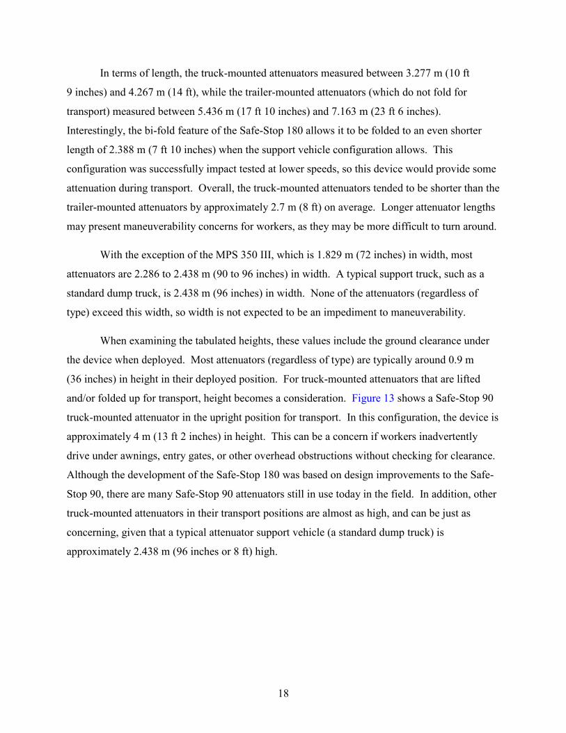
Table 4 shows the approximate weights and dimensions of these mobile attenuators.
Table 4. Dimensions and Masses of Mobile Attenuators.
Device Length
(m) (ft-in)
Width (m) (in)
Height When
Deployed (m) (in)
Height When
Stowed (m)
(ft-in)
Mass (kg) (lb)
TL-3 Truck-Mounted Attenuators
U-MAD Cushion 100K 3.277 10-9
2.286 90
0.762 30
3.785 12-5
570 1256
SAFE-STOP 90 4.013 13-2
2.362 93
0.914 36
4.013 13-2
905 1996
SAFE-STOP 180 4.191 13-9
2.362 93
0.914 36
2.083 6-10
943 2080
MPS 350 III 4.267 14-0
1.829 72
0.762 30
3.81 12-6
816 1800
Scorpion C10000 3.556 11-8
2.438 96
0.635 25
3.658 12-0
632 1393
TL-3 Trailer-Mounted Attenuators
U-MAD 100k Trailer 6.477 21-3
2.286 90
0.914 36 N/A 1266
2790
SAFE-STOP SST Trailer 5.867 19-3
2.362 93
1.143 45 N/A 1202
2650
Vorteq Trailer 6.934 22-9
2.337 92
0.787 31 N/A 594
1310
Scorpion Trailer 5.436 17-10
2.438 96
0.914 36 N/A 785
1730
TTMA-100 Trailer 7.163 23-6
2.438 96
0.940 37 N/A 658
1450
18
In terms of length, the truck-mounted attenuators measured between 3.277 m (10 ft
9 inches) and 4.267 m (14 ft), while the trailer-mounted attenuators (which do not fold for
transport) measured between 5.436 m (17 ft 10 inches) and 7.163 m (23 ft 6 inches).
Interestingly, the bi-fold feature of the Safe-Stop 180 allows it to be folded to an even shorter
length of 2.388 m (7 ft 10 inches) when the support vehicle configuration allows. This
configuration was successfully impact tested at lower speeds, so this device would provide some
attenuation during transport. Overall, the truck-mounted attenuators tended to be shorter than the
trailer-mounted attenuators by approximately 2.7 m (8 ft) on average. Longer attenuator lengths
may present maneuverability concerns for workers, as they may be more difficult to turn around.
With the exception of the MPS 350 III, which is 1.829 m (72 inches) in width, most
attenuators are 2.286 to 2.438 m (90 to 96 inches) in width. A typical support truck, such as a
standard dump truck, is 2.438 m (96 inches) in width. None of the attenuators (regardless of
type) exceed this width, so width is not expected to be an impediment to maneuverability.
When examining the tabulated heights, these values include the ground clearance under
the device when deployed. Most attenuators (regardless of type) are typically around 0.9 m
(36 inches) in height in their deployed position. For truck-mounted attenuators that are lifted
and/or folded up for transport, height becomes a consideration. Figure 13 shows a Safe-Stop 90
truck-mounted attenuator in the upright position for transport. In this configuration, the device is
approximately 4 m (13 ft 2 inches) in height. This can be a concern if workers inadvertently
drive under awnings, entry gates, or other overhead obstructions without checking for clearance.
Although the development of the Safe-Stop 180 was based on design improvements to the Safe-
Stop 90, there are many Safe-Stop 90 attenuators still in use today in the field. In addition, other
truck-mounted attenuators in their transport positions are almost as high, and can be just as
concerning, given that a typical attenuator support vehicle (a standard dump truck) is
approximately 2.438 m (96 inches or 8 ft) high.

19
Figure 13. Safe-Stop 90 in Upright Position for Transport.
MANEUVERABILITY
In the early evaluations of mobile attenuators, researchers found that TxDOT workers
had some concerns about their use. They felt that the effects of the mobile attenuators on support
truck maneuverability were detrimental. In addition, the support vehicle used for the attenuator
had limited maintenance utility, since it was not available to perform other functions. Finally,
the need for another worker to drive the support vehicle was often seen as a waste of manpower
(47).
As mentioned earlier, longer attenuator lengths, particularly with trailer-mounted
attenuators, may impact maneuverability. For example, if workers are on a two-lane roadway in
a rural area, there may be limited opportunities to turn around. Some TxDOT crews have
reported having to travel several miles away from the work area to find a suitable place to turn
around while towing trailer-mounted attenuators.
With the limited resources available in today’s transportation environment, TxDOT has
shown an interest in combining functions when feasible. One such idea involves eliminating the

20
use of a shadow vehicle during herbicide application operations if the herbicide application truck
could carry or tow its own attenuator. This would reduce the number of workers and vehicles
required to perform herbicide application. Unfortunately, the loss of maneuverability is
significant when either truck-mounted or trailer-mounted attenuators are attached to work
vehicles. Truck position is critical during herbicide application operations and TxDOT workers
must be careful to position the sprayer truck such that sprayer nozzles reach the appropriate areas
to be treated. This typically requires significant maneuvering of the work vehicle during the
operation, and the restricted maneuverability due to the attenuator makes this scenario difficult,
if not impossible to achieve.
SUMMARY
As mentioned in the previous section, many of the attenuators require some type of
modification to the rear bumper area of support vehicles to accommodate the carrying or towing
of the attenuator. Because these fleet vehicles cannot perform both attenuator support vehicle
functions and work functions at the same time, TxDOT districts typically dedicate certain
vehicles to carry or tow attenuators and the vehicle is specifically set up solely for that purpose.
Approximately 150 TxDOT fleet trucks are primarily used as attenuator support vehicles. Thus,
the loss of utility of support vehicles noted in earlier research is still prevalent today (47).
While each device is unique in size and shape, truck-mounted attenuators tend to provide
more height challenges for workers in terms of maneuverability, while trailer-mounted
attenuators may be more difficult to turn around. These challenges associated with their utility
do not appear to be any greater for one type of device over the other.
21
CRASHWORTHINESS
Before newly developed roadside safety hardware products can be used on the national
highway system, they must meet certain criteria established by the Federal Highway
Administration (FHWA). Mobile attenuators must be crash tested using full-scale vehicle
impact testing. The impact testing evaluated the performance of the attenuator in terms of the
hazards to which occupants of the impacting vehicle would be exposed, the structural adequacy
of the attenuator, the hazard to workers and pedestrians located nearby due to debris resulting
from the impact, and the post-impact behavior of the test vehicle. FHWA prescribes specific
impact conditions for the testing, including vehicle mass, speed, approach angle, and the point on
the attenuator to be hit. In addition, FHWA prescribes acceptable measurement tolerances and
techniques for each element of the testing. Proper documentation of the impacting testing data,
including a comprehensive report, must be submitted to FHWA for review.
FHWA reviews the documentation to determine if it meets crash performance criteria. If
the criteria are met, FHWA issues an acceptance letter. While the acceptance letter typically
states that use of the attenuator on the national highway system is acceptable, it addresses only
the crashworthiness characteristics of the attenuator. It does not address moisture, vibration, and
durability testing, nor does it address other agency approvals that are typically required prior to
deployment. Table 5 lists the acceptance letters issued by FHWA for mobile attenuators that are
currently on the TxDOT Compliant Work Zone Traffic Control Devices List (46).

22
Table 5. FHWA Acceptance Letters for Mobile Attenuators (48). Device Manufacturer of Record FHWA Acceptance Letter
TL-3 Truck-Mounted Attenuators U-MAD Cushion 100K Barrier Systems CC-64, CC-64A, CC-64D, CC-64G Alpha 100K Energy Absorption Systems CC-39 SAFE-STOP Energy Absorption Systems CC-59, CC-59A, CC-59B SAFE-STOP 180 Energy Absorption Systems CC-78, CC-78A, CC-78B Ram 100K Renco CC-67 MPS 350 III Trinity CC-34, CC-34A, CC-34B Scorpion C10000 TrafFix CC-65, CC-65A
TL-3 Trailer-Mounted Attenuators U-MAD 100k Barrier Systems CC-99, CC-103 SAFE-STOP SST Energy Absorption Systems CC-78C, CC-78D Vorteq Energy Absorption Systems CC-104, CC-104A Scorpion TrafFix CC-65B, CC-65C, C-65E
TTMA-100 Safety Trailers (now Gregory Industries) CC-90, CC-90A
TL-2 Truck-Mounted Attenuators Alpha 70K Energy Absorption Systems CC-32 Ren-Gard 815 Renco CC-20, CC-20A Scorpion A 10000 TrafFix CC-65F
TL-2 Trailer-Mounted Attenuators U-MAD 70k Barrier Systems CC-64B, CC-64E, CC-64F, CC-64G
The requirements for full-scale impact testing have recently changed. These changes
were intended to more accurately reflect changes in the vehicle fleet. Vehicles have increased in
size and light truck bumper heights are increasing. A brief discussion of the current and previous
test criteria are presented in this section.
MASH TESTING
The current crashworthiness testing requirements for mobile attenuators are defined in
the Manual for Assessing Safety Hardware (49), commonly referred to as MASH. As of January
1, 2011, all new products must be tested using MASH test criteria. Retesting of devices that
were already accepted under the previous test criteria is not required. Changes to the test vehicle
masses found in MASH were intended to make the impacting vehicles used in the testing more
representative of the modern vehicle fleet. The recommended MASH impact test matrix for
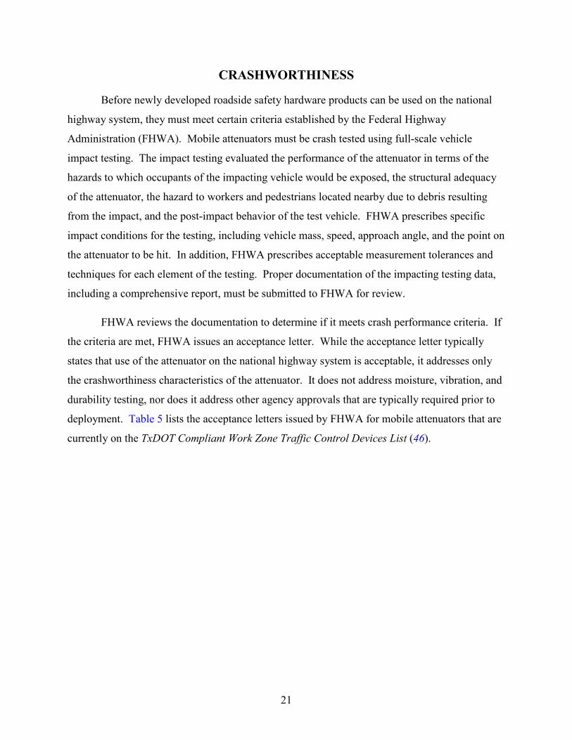
mobile attenuators is given in Table 6 and is illustrated in Figure 14.
23
Table 6. MASH Test Level 3 Impact Tests for Mobile Attenuators (49).
Test Conditions MASH Test Number 3-50 3-51 3-52 3-53
Impacting Vehicle
Mass (kg) (lb)
1100 2420
2270 5000
2270 5000
2270 5000
Speed (km) (mph)
100 62
100 62
100 62
100 62
Impact Conditions
Impact Point Centerline Centerline Offset (W/3) Offset (W/4)
Alignment Head-On (0 deg)
Head-On (0 deg)
Head-On (0 deg)
Angled (10 deg)
Support Vehicle Criteria
Mass Heaviest Allowable
Heaviest Allowable
Heaviest Allowable
Lightest Allowable
Engine Off Off Off Off Transmission 2nd gear 2nd gear 2nd gear 2nd gear Parking Brake On/Set On/Set On/Set On/Set
Restraint
Rigid/Blocked in lieu of Heaviest Available
Rigid/Blocked in lieu of Heaviest Available
Rigid/Blocked in lieu of Heaviest Available
No external restraint

24
Figure 14. MASH Impact Tests for Mobile Attenuators (49).
Although MASH is the current standard for impact testing, none of the mobile attenuators
currently in use have been tested using these protocols. Instead, they were developed while the
previous impact testing protocols were still in effect. The test matrix is provided in this report
for informational purposes only.
25
NCHRP 350 TESTING
Prior to the introduction of the MASH testing criteria, mobile attenuators were evaluated
using testing protocols that are defined in National Cooperative Highway Research Program
Report 350 Recommended Procedures for the Safety Performance Evaluation of Highway
Features (50). This protocol has been in use since 1993.
Mobile Attenuator Test Parameters
It is important to understand that vehicle impact tests are complex experiments and are
difficult to replicate because of imprecise controls of test conditions and sometimes random and
unstable behavior of dynamic crush and fracture mechanisms. As a result, FHWA is faced with
the challenge of making acceptance decisions based on single impact test reports. There is no
guarantee that the attenuator will perform in the exact same manner under all conditions found in
the field, but impact testing is still the best tool available for evaluating impact performance. For
this reason, a considerable effort is made to maintain the uniformity of tests that may be
performed by many different testing facilities.
For tests that include the small car (820C), the support vehicle should be placed against a
rigid barrier to prevent any forward movement. This effectively maximizes the deceleration of
the impacting vehicle and represents the worst case condition for occupants of a small car during
a real collision with a mobile attenuator.
For tests that include the pickup truck (2000P), the support vehicle should be placed on a
clean, dry, paved surface, such as asphaltic or portland cement concrete surfaces. In addition, the
supporting vehicle should be in second gear with the parking brakes on. The front tires of the
support vehicle should be aimed directly ahead.
Curb mass is the mass of a test vehicle in its standard manufactured condition, which
does not include vehicle occupants or cargo, but all fluid reservoirs are filled. Test inertial mass
is the mass of test vehicle and all items including ballast and test equipment that is rigidly
attached to the vehicle structure. Mass of test dummies is not included. Gross static mass is the
total of test inertial mass and dummy mass combined.
26
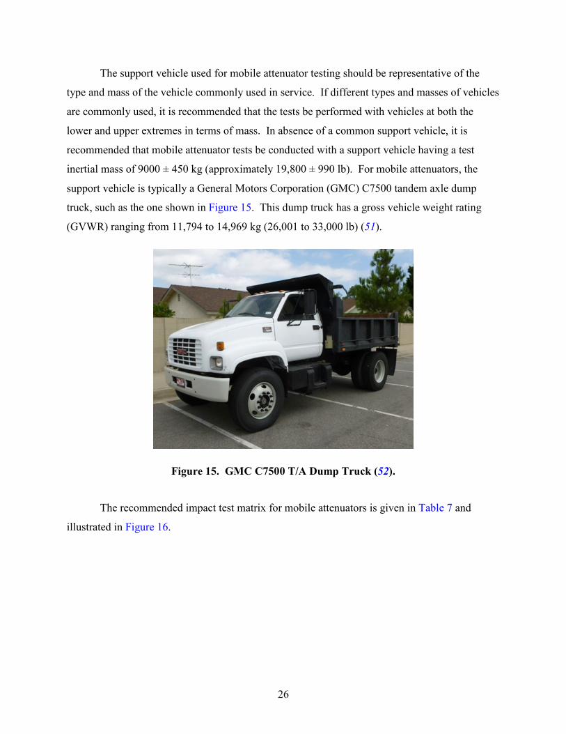
The support vehicle used for mobile attenuator testing should be representative of the
type and mass of the vehicle commonly used in service. If different types and masses of vehicles
are commonly used, it is recommended that the tests be performed with vehicles at both the
lower and upper extremes in terms of mass. In absence of a common support vehicle, it is
recommended that mobile attenuator tests be conducted with a support vehicle having a test
inertial mass of 9000 ± 450 kg (approximately 19,800 ± 990 lb). For mobile attenuators, the
support vehicle is typically a General Motors Corporation (GMC) C7500 tandem axle dump
truck, such as the one shown in Figure 15. This dump truck has a gross vehicle weight rating
(GVWR) ranging from 11,794 to 14,969 kg (26,001 to 33,000 lb) (51).
Figure 15. GMC C7500 T/A Dump Truck (52).
The recommended impact test matrix for mobile attenuators is given in Table 7 and
illustrated in Figure 16.

27
Table 7. NCHRP Report 350 Test Level 3 Impact Tests for Mobile Attenuators.
Test Conditions NCHRP Report 350 Test Number 3-50 3-51 3-52 3-53
Impacting Vehicle
Mass (kg) (lb)
820 1800
2000 4400
2000 4400
2000 4400
Speed (km) (mph)
100 62
100 62
100 62
100 62
Impact Conditions
Impact Point Centerline Centerline Offset (W/3)
Offset (W/4)
Alignment Head-On (0 deg)
Head-On (0 deg)
Head-On (0 deg)
Angled (10 deg)
Support Vehicle Criteria
Mass (lb) N/A N/A N/A N/A Engine Off Off Off Off Transmission 2nd gear 2nd gear 2nd gear 2nd gear Parking Brake On/Set On/Set On/Set On/Set Restraint Rigid/Blocked N/A N/A N/A

28
Figure 16. NCHRP Report 350 Impact Tests for Mobile Attenuators (50).
Test 3-50 is intended to evaluate risks to occupants of a small car impacting the mobile
attenuator. During this test, the 820C (1800 lb) small car strikes the mobile attenuator head on
and centered. An instrumented test dummy located in the front seat of the small car collects data
during the impact.
29
Test 3-51 is intended to evaluate structural adequacy of the mobile attenuator, risks to
occupants, and the roll-ahead distance of the support vehicle when impacted by the heavy
passenger vehicle. Occupant risk is measured in terms of occupant impact velocity and
ridedown acceleration. Roll-ahead distance is the distance the support vehicle moves after
impact, and it is important to consider when selecting safe separation distances from the support
vehicle and workers on foot near the support vehicle.
Test 3-52 is an optional test that is performed with the centerline of the impacting vehicle
offset one third of the width of the impacting vehicle. Test 3-53 is an optional test that is
performed with the centerline of the impacting vehicle offset one-fourth of the width of the
impacting vehicle and at an impact angle of 10 degrees. When these test standards were
developed, there was no assurance that any mobile attenuator design could meet the 3-52 and
3-53 test requirements and still be a feasible design. For this reason, these two tests were
optional for truck-mounted attenuators, even though the impact conditions for 3-52 and 3-53 are
believed to be representative of many collisions that occur with mobile attenuators.
Evaluation/Passing Criteria
The recommended test matrix for mobile attenuators only addresses safety performance
during vehicular collisions. It does not address durability, mobility of the support vehicle, road-
induced vibration, maintainability, influence of temperature variations and moisture, and other
factors. The safety performance is evaluated based on specific evaluation criteria. The
evaluation criteria fall into three categories: structural adequacy, occupant risk, and post-impact
vehicle response. Impact test results are compared to evaluation criteria to determine acceptable
performance of the mobile attenuator.
Structural Adequacy
Mobile attenuator products that satisfy the structural adequacy requirements should stop
the impacting vehicle in a controlled manner. This is readily evident from the impact testing.
The structural adequacy criteria refer to the structural requirements associated with the impact
and do not address structural requirements of wind, ice, and other environmental loads that may
occur.

30
Occupant Risk
Occupant risk relates to the degree of hazard to which occupants of the impacting vehicle
are subjected and is primarily measured in terms of (1) occupant impact velocity and (2)
occupant ridedown accelerations.
Occupant Impact Velocities. Occupant Impact Velocities (OIV) is the velocity at which
a hypothetical point mass occupant impacts a surface of a hypothetical occupant compartment.
More simply stated, this is the velocity at which a vehicle occupant’s head strikes the interior of
the vehicle during a collision. Maximum acceptable longitudinal OIV is 12 m/s (or 39.4 ft/s) and
should preferably be limited to 9 m/s (29.5 ft/s) in the longitudinal and lateral directions.
Occupant Ridedown Acceleration. Occupant ridedown acceleration is the highest
lateral and longitudinal component of resultant vehicular acceleration averaged over any 10-ms
interval for the collision pulse subsequent to occupant impact. This value should preferably be
limited to 15 G in the longitudinal and lateral directions, with a maximum of no more than 20 G,
where G equals 9.81 m/s2 (32.2 ft/s2).
Other Factors. Other aspects of occupant risk relate to detached elements, fragments, or
other debris from the mobile attenuator, which should not penetrate or show potential for
penetrating the occupant compartment of the impacting vehicle, nor should it present an undue
hazard to other traffic, pedestrians, or workers. In addition, deformation of the occupant
compartment, or intrusion into the occupant compartment, that may cause serious injuries should
not be permitted. Finally, the impacting vehicle should remain upright during and after the
collision. Moderate roll, pitching, and yawing are acceptable. Figure 17 illustrates the concepts
of roll, pitch, and yaw with the recommended sign conventions for test records. Roll data
capture the tipping motion of the impacting vehicle about an imaginary horizontal axis through
the center of the vehicle and aligning with the vehicle travel path. Pitch data capture the bucking
motion of the impacting vehicle about an imaginary lateral axis through the center of the vehicle.
Finally, yaw data capture the spinning motion of the impacting vehicle about an imaginary
vertical axis through the center of the vehicle. Higher values of roll, pitch, and yaw may indicate
undesirable conditions for the occupants of the impacting vehicle.

31
Figure 17. Sign Conventions for Measuring Roll, Pitch and Yaw (50).
Post-Impact Vehicle Trajectory
Post-impact vehicle response is a measure of the potential interaction of the impacting
vehicle with other traffic after the crash. A subsequent multivehicle crash can subject occupants
of other vehicles to undue hazard. NCHRP Report 350 indicates that it is preferable that the
vehicle’s trajectory not intrude into adjacent lanes and that and the impacting vehicle’s final
stopping position intrude a minimum distance, if at all, into adjacent or opposing traffic lanes.
TXDOT TESTING CRITERIA AND EVALUATION
Mobile attenuators that are currently in use by TxDOT have received letters of
acceptance from FHWA based on testing performed under NCHRP Report 350. There is no
deadline for states to switch over to MASH-tested hardware, since all hardware tested under
NCHRP Report 350 may remain in place and may continue to be manufactured and installed
(49).
TxDOT Specification No. 550-42-09 (53) dated June 2010 describes purchasing
requirements for truck-mounted attenuators. Table 8 shows the design and performance
requirements for Test Level 3 mobile attenuators described in this specification.

32
Table 8. TxDOT TL-3 Impact Testing Requirements per Specification 550-42-09 (53).
Test Conditions Test Number 3-50 3-51 3-52 3-53
Impacting Vehicle
Mass (kg) (lb)
820 1800
2000 4400 N/A N/A
Speed (km) (mph)
100 62
100 62 N/A N/A
Impact Conditions
Impact Point Centerline Centerline N/A N/A
Alignment Head-On (0 deg)
Head-On (0 deg) N/A N/A
Support Vehicle Criteria
Mass (kg) (lb)
8550 to 9450 18,849 to 20,833
Single Axle Dual Rear Tires
8550 to 9450 18,849 to 20,833
Single Axle Dual Rear Tires
N/A N/A
Engine Off Off N/A N/A Transmission 2nd gear 2nd gear N/A N/A Parking Brake On/Set On/Set N/A N/A
Restraint N/A N/A N/A N/A
The specification requires only Tests 3-50 and 3-51, which were the only required tests
for truck-mounted attenuators under NCHRP Report 350 when the specification was published.
Tests 3-52 and 3-53 were determined by NCHRP Report 350 to be optional for truck-mounted
attenuators and thus, were not included in the TxDOT specification. The specification requires
that a support vehicle with a mass of 8550 to 9450 kg (18,849 to 20,833) lb should be used
during the impact testing. TxDOT does not currently have a specification for the purchase of
trailer-mounted attenuators.
The truck-mounted attenuator specification gives the recommended passing criteria for
truck-mounted attenuators, and these are shown in Table 9.
Table 9. TxDOT Passing Criteria for Impact Testing. Passing Criteria Limits Maximum Occupant Impact Velocity Longitudinally Not to exceed 39.4 fps Maximum Occupant Ridedown Acceleration Longitudinally Not to exceed 20 G Impact Vehicle Rollover Not permitted Impact Vehicle Lane Intrusion Stopped within its lane Impact Vehicle Passenger Compartment Integrity Reasonably Safeguarded Impact Acceleration of Stationary Support Vehicle Minimized Roll-Ahead Distance Minimized

33
Although the specification reasonably follows the requirements of NCHRP Report 350,
the Impact Vehicle Lane Intrusion requirement that the vehicle is stopped within its lane may be
too stringent for most mobile attenuators.
The Compliant Work Zone Traffic Control Devices List (46) provides a list of
crashworthy products for contractors to use, purchase or rent for use on TxDOT projects. It
includes both truck-mounted and trailer-mounted attenuators. This document has specific
language regarding the required mass for support vehicles used for mobile attenuators during
work operations on TxDOT roadways:
The supporting vehicle shall have a gross (i.e., ballasted) vehicular weight of 20,000 ± 1000 lb unless another weight is recommended by the TMA [Truck Mounted Attenuator] manufacturer. If a contractor chooses to use a lighter vehicle to mount the TMA, then the contractor is responsible for following the TMA manufacturer’s recommendations and for being aware of the effect that a lighter vehicle will have on the roll-ahead distance and on the driver of the shadow vehicle. Attachment of TMA shall be in accordance with manufacturer’s recommendations.


35
WORKER SAFETY ASSESSMENT
COLLISION DYNAMICS
To understand impact testing, one must understand the basic principles of collision
dynamics. When two vehicles collide, the interaction follows the principle of conservation of
momentum. Momentum is the product of vehicle mass and velocity. The sum the vehicle
momentum just prior to the impact equals the sum of the momentum of the vehicles just after
impact, as shown in the following equation:
𝑀𝐼𝑉𝐼 + (𝑀𝑆 + 𝑀𝐴)𝑉𝑆 = (𝑀𝐼 + 𝑀𝑆 + 𝑀𝐴)𝑉𝑇
Where:
𝑀𝐼=mass of impacting vehicle, kg (slugs).
𝑉𝐼=impact speed of impacting vehicle, m/s (fps).
𝑀𝑆=mass of support vehicle, kg (slugs).
𝑀𝐴=mass of attenuator, kg (slugs).
𝑉𝑆=impact speed of support vehicle and attenuator (𝑉𝑆=0 for stationary condition), m/s (fps).
𝑉𝑇=post impact speed of impacting vehicle (𝑉𝐼), support vehicle and attenuator (𝑉𝑆), m/s (fps).
The support vehicle speed (𝑉𝑆) is applicable to both the support vehicle and the
attenuator because they are connected. Although the attenuator is crushed in the impact, it has
the same mass, but it is simply more compact. Interestingly, other than contributing mass, the
energy absorbing properties of the attenuator are not applicable in this equation. With all other
elements known, 𝑉𝑇 can be calculated. Using Test 3-50 and 3-51 data obtained from the FHWA
acceptance letters for each attenuator, the researchers calculated values for 𝑉𝑇 for each of the
mobile attenuators. The results are shown in Table 10 and Table 11, respectively. Under crash
test conditions, 𝑉𝑆=0.
36
Table 10. Post Impact Speeds Calculated from 3-50 Test Data.
Attenuator Type 𝑀𝐼
(kg) (lb)
𝑉𝐼 (m/s) (mph)
𝑀𝑆 (kg) (lb)
𝑀𝐴 (kg) (lb)
𝑉𝑇 (m/s) (mph)
U-MAD Cushion 100K Truck 820 1808
27.8 62.2
9183 20,245
570 1257
2.2 4.9
SAFE-STOP 180 Truck 903 1991
27.1 60.6
8550 18,850
940 2072
2.4 5.4
Ram 100K Truck 896 1975
26.4 59.1
8849 19,509
427 941
2.3 5.1
MPS 350 III Truck 915 2017
27.8 62.2
9000 19,842
640 1411
2.4 5.4
Scorpion C10000 Truck 883 1947
27.8 62.2
9632 21,235
632 1393
2.2 4.9
Vorteq Trailer 885 1951
27.7 62.0 N/A* 594
1310 N/A
TTMA-100 Trailer 897 1978
26.7 59.7
9659 21,294
659 1453
2.1 4.7
*support vehicle blocked from forward movement
Table 11. Post Impact Speeds Calculated from 3-51 Test Data.
Attenuator Type 𝑀𝐼
(kg) (lb)
𝑉𝐼 (m/s) (mph)
𝑀𝑆 (kg) (lb)
𝑀𝐴 (kg) (lb)
𝑉𝑇 (m/s) (mph)
U-MAD Cushion 100K Truck 2000 4409
27.8 62.2
9183 20,245
570 1257
4.7 10.5
SAFE-STOP 180 Truck 1998 4405
26.8 59.9
8550 18,850
940 2072
4.7 10.5
Ram 100K Truck 2000 4409
27.9 62.4
8849 19,509
427 941
4.9 11.0
MPS 350 III Truck 2041 4500
27.8 62.2
9000 19,842
640 1411
4.9 11.0
Scorpion C10000 Truck 1961 4323
27.5 61.5
9632 21,235
632 1393
4.4 9.8
U-MAD 100k Trailer 2242 4943
27.0 60.4
9884 21,790
1148 2531
4.6 10.2
SAFE-STOP SST Trailer 2000 4409
27.5 61.5
8550 18,850
1202 2650
4.7 10.5
Vorteq Trailer 1999 4407
28.3 63.3 N/A* 594
1310 N/A
Scorpion Trailer 2034 4484
27.0 60.4 N/A* 701
1545 N/A
TTMA-100 Trailer 2012 4436
27.6 61.7
9659 21,294
659 1453
4.5 10.1
*support vehicle blocked from forward movement

37
𝑉𝑇 is an important factor in determining post impact movement of the support vehicle.
The results indicate very small variations in computed 𝑉𝑇 values. Although most of the
prescribed impact test parameters (such as 𝑀𝐼 and 𝑉𝐼) have small variations, a quick review
indicates that variations in the mass of the support vehicle are often much greater. In this case,
the U-MAD trailer has the lowest calculated 𝑉𝑇 value. This does not mean that the energy
absorbing capability of this attenuator is greater than the others. The higher 𝑉𝑇 value is due to
the greater mass of the support vehicle used in the testing as well as the greater mass of the
attenuator. If no attenuator were present (𝑀𝐴=0), we would not expect to see much difference in
calculated values of 𝑉𝑇.
To support this idea, the researchers performed a sensitivity analysis by calculating
theoretical values of 𝑉𝑇 for a standard set of conditions, assuming: 𝑀𝐼=820 kg, 𝑉𝐼=27.8 m/s
(100 km/hr), 𝑀𝑆=9000 kg, and 𝑉𝑆=0 (for stationary condition), while the value for 𝑀𝐴 ranged
from 0 to 1500 kg. These same calculations were repeated for 𝑀𝐼=2000 kg. In addition,
calculated values of 𝑉𝑇 from the impact test data were plotted on the same graph with the
theoretical data. Figure 18 shows the results.

38
Figure 18. VT as a Function of MA.
It appears that the computed values of 𝑉𝑇 are well-correlated, regardless of attenuator
type. But this graph also tells us that when the mass of the impacting vehicle is significantly
increased (from 820 kg to 2000 kg), then the expected value of 𝑉𝑇 also increases significantly.
To further examine this concept, the researchers computed 𝑉𝑇 for various values of 𝑀𝐼 (ranging
from 820 kg to 36300 kg) and 𝑀𝑆 (ranging from 2270 kg to 9000 kg) while assuming an average
value of 𝑀𝐴=650 kg. Figure 19 shows the results.

39
Figure 19. VT for Various Values of MI and MS.
Figure 19 demonstrates that 𝑉𝑇 decreases when 𝑀𝑆 increases. 𝑉𝑇 also decreases when 𝑀𝐼
decreases. Lower values of 𝑉𝑇 indicate more favorable circumstances for workers. When
considering methods that could be used to lower values of 𝑉𝑇 during an actual impact, it is
important to understand that there is no way to control the mass of the impacting vehicle (𝑀𝐼)
during a random impact. However, the mass of the support vehicle (𝑀𝑆) is something that can
be controlled by strict enforcement of agency policies that require heavier support vehicles.
COMPARISON OF MOBILE ATTENUATOR TYPES
The researchers first examined the impact testing results in terms of safety of the
occupants of the impacting vehicle. Occupant impact velocity (OIV) and ridedown acceleration
are the two primary indicators of impacting vehicle occupant safety. OIV is the Tests 3-50 and
3-51 are intended to evaluate risks to occupants of a small car and pickup truck, respectively,

40
during mobile attenuator impacts. The researchers plotted OIV against ridedown acceleration for
all of the available test data. Figure 20 shows the results.
Figure 20. Impacting Vehicle Occupant Safety Indicators.
Several of the trailer-mounted attenuators were never subjected to test 3-50, so there are
few data points for comparison of this scenario. Nonetheless, no distinct pattern exists. Based
on the impacting vehicle occupant safety indicators, there does not appear to be a clear difference
between the two types of mobile attenuators. The primary differences, such as attenuator
connection type and the addition of an axle, would not be expected to significantly impact OIV
values.
WORKER PROTECTION
The researchers sought to determine if any differences exist between the data for the two
types of mobile attenuators in terms of worker safety. The primary indicators of worker safety

41
are support vehicle occupant ridedown acceleration and support vehicle roll-ahead distance. To
a lesser extent, post-impact vehicle trajectory and flying debris should also be considered.
Support Vehicle Occupant Ridedown Acceleration
When a mobile attenuator impact occurs, there is some risk of injury to the driver of the
support vehicle. Most mobile attenuator impacts are unidirectional (head-on) in nature and cause
the support vehicle to be accelerated forward. Initially, the driver will not move forward, but is
restrained from flailing rearward by the support of the seat and headrest. Rearward occupant
movement is generally less dangerous than forward movement. Ridedown acceleration of the
support vehicle is the recommended criteria for the assessment of the risk of injury to the driver
of the support vehicle (50). Unfortunately, detailed impact crash data are not available for this
calculation and are not required to be reported from impact testing. However, researchers know
that support vehicle accelerations will be significantly less than accelerations measured on the
impacting vehicle if the support vehicle weighs significantly more than the impacting vehicle
(47). Therefore, the use of a heavier support vehicle reduces the risk of injury for the driver of
the support vehicle.
Support Vehicle Roll-Ahead
One of the major safety concerns with the used of mobile attenuators is roll-ahead
distance. Roll-ahead distance defined as the longitudinal displacement of the support vehicle
when impacted by an errant vehicle. Table 12 and Table 13 show the expected roll-ahead
distances for moving and stationary operations, respectively, as a function of impact speed,
support vehicle mass, and impacting vehicle mass. These tables are based on procedures
developed over two decades ago by Humphries and Sullivan (55). These values are rounded up
to the nearest 25-ft increment.
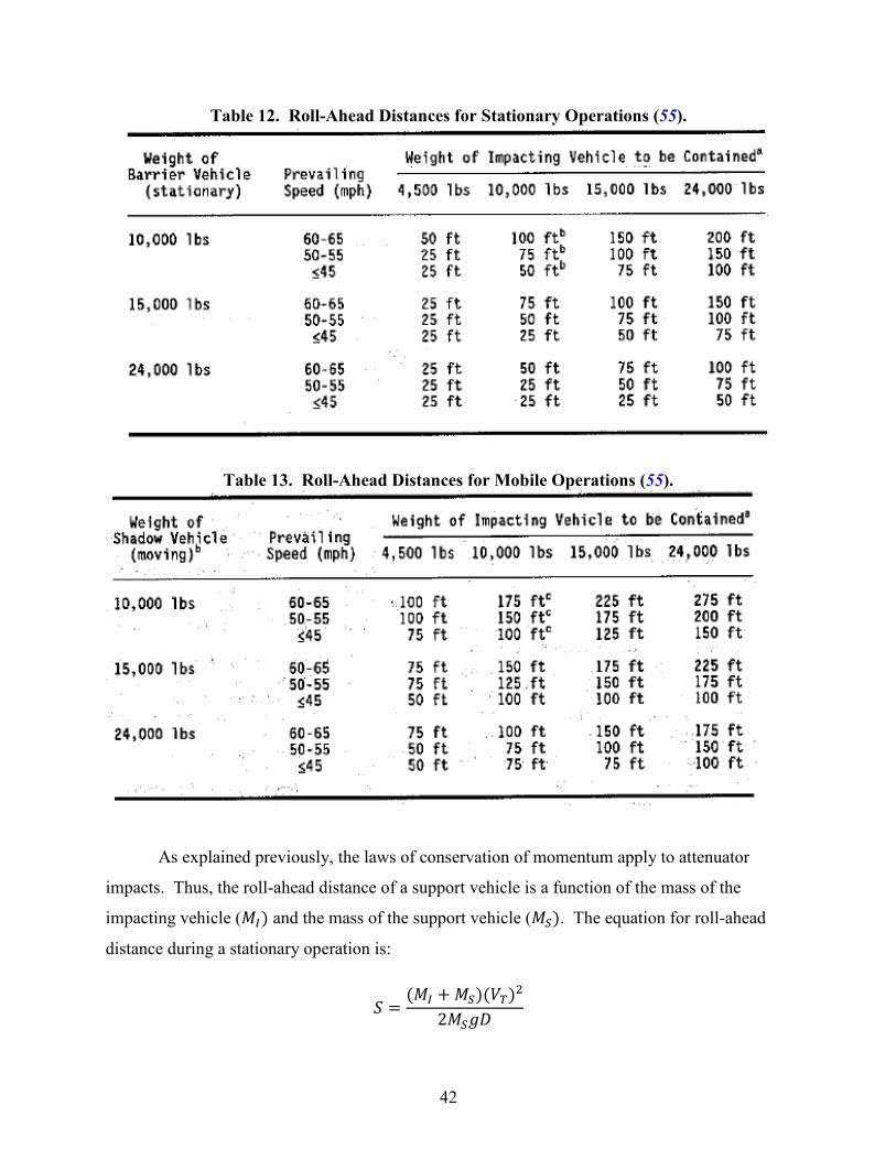
42
Table 12. Roll-Ahead Distances for Stationary Operations (55).
Table 13. Roll-Ahead Distances for Mobile Operations (55).
As explained previously, the laws of conservation of momentum apply to attenuator
impacts. Thus, the roll-ahead distance of a support vehicle is a function of the mass of the
impacting vehicle (𝑀𝐼) and the mass of the support vehicle (𝑀𝑆). The equation for roll-ahead
distance during a stationary operation is:
𝑆 =(𝑀𝐼 + 𝑀𝑆)(𝑉𝑇)2
2𝑀𝑆𝑔𝐷

43
Where
𝑆=roll-ahead distance, m (ft).
𝑀𝐼=mass of impacting vehicle, kg (slugs).
𝑀𝑆=mass of support vehicle, kg (slugs).
𝑔=gravitational constant, 9.8 m/s (32.2 fps2).
𝐷=drag factor of support vehicle, typically less than full braking (unitless).
𝑉𝑇=post impact speed of both impacting vehicle (𝑉𝐼) and support vehicle (𝑉𝑃=0 for stationary
condition), m (ft).
𝑉𝐼=impact speed of impacting vehicle, m/s (fps).
The equation for 𝑉𝑇 was established earlier in this report and is shown below:
𝑉𝑇 =𝑀𝐼𝑉𝐼
𝑀𝐼 + 𝑀𝑠 + 𝑀𝐴
By solving the roll-ahead equation for 𝐷 and substituting the 𝑉𝑇 equation, the new equation is:
𝐷 = 𝑉𝐼2(𝑀𝐼)2
2 𝑀𝑆 (𝑀𝐼 + 𝑀𝑠 + 𝑀𝐴) 𝑔 𝑆
When impact testing is performed with the support vehicle in second gear and the parking
brake(s) set, test results usually state the measured roll-ahead distance. With the impact speed
and all other masses known, the effective drag factor, 𝐷, can be calculated. Using impact test
data available at the time for a variety of truck-mounted attenuators, Humphreys and Sullivan
found that the effective drag values ranged from 0.2 to 0.7. They assumed an effective drag
factor of 0.3, which is on the lower end of the range (55). Using a more conservative (lower)
value for the effective drag factor in computations will result in slightly higher theoretical roll-
ahead distances.
44
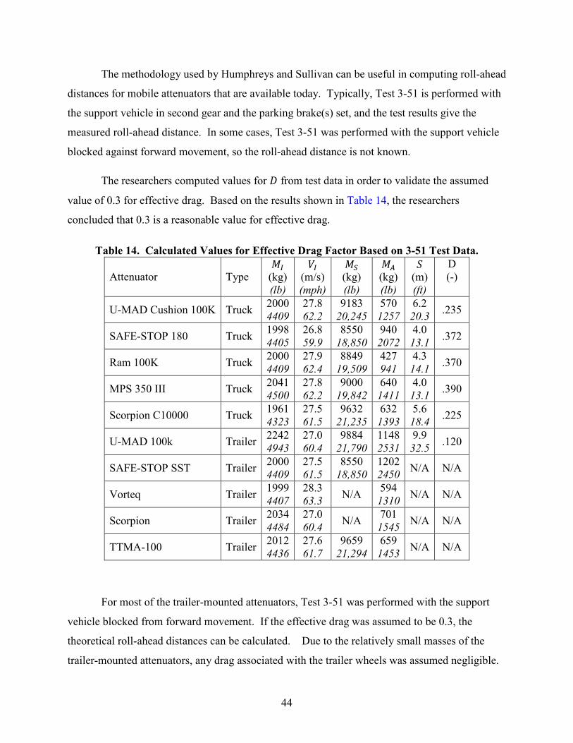
The methodology used by Humphreys and Sullivan can be useful in computing roll-ahead
distances for mobile attenuators that are available today. Typically, Test 3-51 is performed with
the support vehicle in second gear and the parking brake(s) set, and the test results give the
measured roll-ahead distance. In some cases, Test 3-51 was performed with the support vehicle
blocked against forward movement, so the roll-ahead distance is not known.
The researchers computed values for 𝐷 from test data in order to validate the assumed
value of 0.3 for effective drag. Based on the results shown in Table 14, the researchers
concluded that 0.3 is a reasonable value for effective drag.
Table 14. Calculated Values for Effective Drag Factor Based on 3-51 Test Data.
Attenuator Type 𝑀𝐼
(kg) (lb)
𝑉𝐼 (m/s) (mph)
𝑀𝑆 (kg) (lb)
𝑀𝐴 (kg) (lb)
𝑆 (m) (ft)
D (-)
U-MAD Cushion 100K Truck 2000 4409
27.8 62.2
9183 20,245
570 1257
6.2 20.3 .235
SAFE-STOP 180 Truck 1998 4405
26.8 59.9
8550 18,850
940 2072
4.0 13.1 .372
Ram 100K Truck 2000 4409
27.9 62.4
8849 19,509
427 941
4.3 14.1 .370
MPS 350 III Truck 2041 4500
27.8 62.2
9000 19,842
640 1411
4.0 13.1 .390
Scorpion C10000 Truck 1961 4323
27.5 61.5
9632 21,235
632 1393
5.6 18.4 .225
U-MAD 100k Trailer 2242 4943
27.0 60.4
9884 21,790
1148 2531
9.9 32.5 .120
SAFE-STOP SST Trailer 2000 4409
27.5 61.5
8550 18,850
1202 2450 N/A N/A
Vorteq Trailer 1999 4407
28.3 63.3 N/A 594
1310 N/A N/A
Scorpion Trailer 2034 4484
27.0 60.4 N/A 701
1545 N/A N/A
TTMA-100 Trailer 2012 4436
27.6 61.7
9659 21,294
659 1453 N/A N/A
For most of the trailer-mounted attenuators, Test 3-51 was performed with the support
vehicle blocked from forward movement. If the effective drag was assumed to be 0.3, the
theoretical roll-ahead distances can be calculated. Due to the relatively small masses of the
trailer-mounted attenuators, any drag associated with the trailer wheels was assumed negligible.

45
Table 15. Calculated Values for Roll-Ahead Based on 3-51 Test Data and Drag Factor=0.3.
Attenuator Type 𝑀𝐼
(kg) (lb)
𝑉𝐼 (m/s) (mph)
𝑀𝑆 (kg) (lb)
𝑀𝐴 (kg) (lb)
D (-)
𝑆 (m) (ft)
U-MAD 100K Trailer 2242 4943
27.0 60.4
9884 21,790
1148 2531 0.3* 3.9
12.9
SAFE-STOP SST Trailer 2000 4409
27.5 61.5
8550 18,850
1202 2450 0.3* 5.1
16.7
Vorteq Trailer 1999 4407
28.3 63.3
9000* 19,842
594 1310 0.3* 5.2
17.1
Scorpion Trailer 2034 4484
27.0 60.4
9000* 19,842
701 1545 0.3* 4.9
16.1
TTMA-100 Trailer 2012 4436
27.6 61.7
9659 21294
659 1453 0.3* 4.4
14.4 *assumed value
Because the primary function of a mobile attenuator is to provide protection for
occupants in a striking vehicle, NCHRP Report 350 testing requires the heaviest support vehicle
or a rigidly blocked support vehicle (i.e., roll-ahead distance equals 0 feet) to be used for several
of the required tests. For each crash test performed under NCHRP Report 350, the weight of the
support vehicle is specified. In addition, NCHRP Synthesis 182 describes a method for
calculating roll-ahead distance. The method is based on the concept that the mass (𝑀𝐼) and
speed (𝑉𝐼) of the impacting vehicle and the mass (𝑀𝑆) and drag resistance (𝐷) of the support
vehicle are the primary determinants of roll-ahead distance. Simply stated, using a heavier
support vehicle will provide improved protection for workers that may be located near the
support vehicle, provided that the vehicle weight falls within any limits described in the FHWA
acceptance letter for that particular device.
TxDOT recently amended the Traffic Control Plan (TCP) 6 Series Standard Sheets. The
modifications included the specification of a 30 ft [9.144 m] minimum dimension between the
work location and the position of the protection vehicle during stationary operations (56).
Calculated roll-ahead values shown in Table 15 are at or below the minimum dimension
prescribed by TxDOT.
The researchers also investigated the potential for an herbicide application truck to carry
or tow its own attenuator. This would eliminate the use of a shadow vehicle during herbicide
application operations, thus reducing the number of workers and vehicles required to perform
46
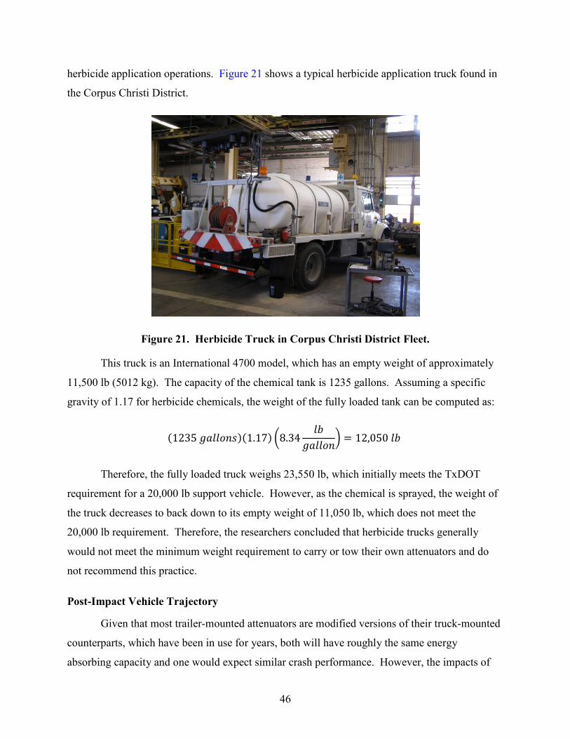
herbicide application operations. Figure 21 shows a typical herbicide application truck found in
the Corpus Christi District.
Figure 21. Herbicide Truck in Corpus Christi District Fleet.
This truck is an International 4700 model, which has an empty weight of approximately
11,500 lb (5012 kg). The capacity of the chemical tank is 1235 gallons. Assuming a specific
gravity of 1.17 for herbicide chemicals, the weight of the fully loaded tank can be computed as:
(1235 𝑔𝑎𝑙𝑙𝑜𝑛𝑠)(1.17) �8.34𝑙𝑏
𝑔𝑎𝑙𝑙𝑜𝑛� = 12,050 𝑙𝑏
Therefore, the fully loaded truck weighs 23,550 lb, which initially meets the TxDOT
requirement for a 20,000 lb support vehicle. However, as the chemical is sprayed, the weight of
the truck decreases to back down to its empty weight of 11,050 lb, which does not meet the
20,000 lb requirement. Therefore, the researchers concluded that herbicide trucks generally
would not meet the minimum weight requirement to carry or tow their own attenuators and do
not recommend this practice.
Post-Impact Vehicle Trajectory
Given that most trailer-mounted attenuators are modified versions of their truck-mounted
counterparts, which have been in use for years, both will have roughly the same energy
absorbing capacity and one would expect similar crash performance. However, the impacts of
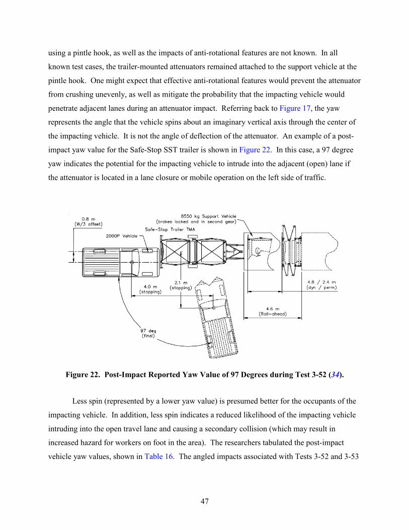
47
using a pintle hook, as well as the impacts of anti-rotational features are not known. In all
known test cases, the trailer-mounted attenuators remained attached to the support vehicle at the
pintle hook. One might expect that effective anti-rotational features would prevent the attenuator
from crushing unevenly, as well as mitigate the probability that the impacting vehicle would
penetrate adjacent lanes during an attenuator impact. Referring back to Figure 17, the yaw
represents the angle that the vehicle spins about an imaginary vertical axis through the center of
the impacting vehicle. It is not the angle of deflection of the attenuator. An example of a post-
impact yaw value for the Safe-Stop SST trailer is shown in Figure 22. In this case, a 97 degree
yaw indicates the potential for the impacting vehicle to intrude into the adjacent (open) lane if
the attenuator is located in a lane closure or mobile operation on the left side of traffic.
Figure 22. Post-Impact Reported Yaw Value of 97 Degrees during Test 3-52 (34).
Less spin (represented by a lower yaw value) is presumed better for the occupants of the
impacting vehicle. In addition, less spin indicates a reduced likelihood of the impacting vehicle
intruding into the open travel lane and causing a secondary collision (which may result in
increased hazard for workers on foot in the area). The researchers tabulated the post-impact
vehicle yaw values, shown in Table 16. The angled impacts associated with Tests 3-52 and 3-53

48
represent the worst cases for which anti-rotational features might be needed. Values of N/A
indicate that data are not available for that scenario (i.e., the test was not performed).
Table 16. Post-Impact Yaw of Impacting Vehicles during Angled Tests.
Attenuator Type Yaw Value (degrees) Test 3-52 Test 3-53
U-MAD Cushion 100K Truck N/A N/A SAFE-STOP 180 Truck -117 -111 Ram 100K Truck N/A N/A MPS 350 III Truck N/A N/A Scorpion C10000 Truck N/A N/A U-MAD 100k1 Trailer -46 N/A SAFE-STOP SST1 Trailer -97 168 Vorteq Trailer 119 111 Scorpion1 Trailer 66 -103 Scorpion (modified anti-rotation system)1 Trailer N/A -52 TTMA-1002 Trailer 140, 135 66
1Claims anti-rotational features 2Additional test conducted after a design modification
Although only one truck-mounted attenuator was subjected to Tests 3-52 and 3-53, the
reported yaw values are comparable to some of the trailers. This may indicate that the concern
of trailer-mounted attenuators swinging around upon impact may not be a significantly higher
risk than when truck-mounted attenuators are utilized, but there are not enough data to make this
conclusion. The Scorpion trailer appears twice in the table because it was re-tested after the
manufacturer made modifications to the anti-rotational feature. The Scorpion trailer, Safe-Stop
SST trailer, and U-MAD trailers all advertise anti-rotational design attributes, while the Vorteq
and TTMA-100 do not. In Test 3-52, the impact is head-on but off center. The Vorteq and
TTMA-100 had higher yaw values in Test 3-52 than the trailers with anti-rotational features,
suggesting that the anti-rotational features have some benefit during this type of impact.
However, these findings are based on a very little test data for each attenuator. Single tests
cannot be construed to represent consistent performance in the field. In Test 3-53, the impact is
both angled and offset. In terms of yaw, the trailers with anti-rotational features did not appear
to perform better than those without, suggesting that anti-rotational features may not effectively
reduce post-impact yaw of the impacting vehicle under the angled test conditions.

49
Flying Debris
When impacted, detached elements, fragments, or other debris from the mobile attenuator
should not penetrate or show potential for penetrating the occupant compartment of the
impacting vehicle. In addition, any flying debris should not show potential for impacting other
vehicles, pedestrians, or workers. Although testing agencies are required to accurately record
and report any debris scatter, there are no established limits by which to judge this aspect for
each mobile attenuator on a pass/fail basis. In addition, these details are not a part of the data
published by FHWA when an acceptance letter is issued.
There is a concern that retrofitting arrow panels to trailer-mounted attenuators may create
a debris hazard for workers if the attenuator were to be struck. Only two trailer-mounted
attenuators were impact tested with arrow panels in place: the Safe-Stop SST trailer (35) and the
Vorteq trailer (44). However, there are no specific FHWA test criteria that would address the
acceptability of attenuator-mounted arrow panels in the impact testing protocols. In the absence
of test criteria, the general assumption would be to check that there is no flying debris from the
arrow panel and that the panel remains affixed to the support structure. With truck-mounted
attenuators, TxDOT has generally mounted the arrow panel to the truck bed when feasible.
Attaching the arrow panel to the support vehicle (i.e., to the tailgate in the case of a dump truck)
would provide more predictable results during impacts. Figure 23 shows a post-impact view of
an arrow panel mounted in this fashion.
Figure 23. Post-Impact View of Arrow Panel on a Safe-Stop Truck-Mounted Attenuator.
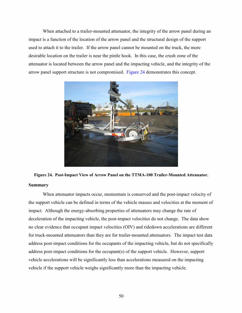
50
When attached to a trailer-mounted attenuator, the integrity of the arrow panel during an
impact is a function of the location of the arrow panel and the structural design of the support
used to attach it to the trailer. If the arrow panel cannot be mounted on the truck, the more
desirable location on the trailer is near the pintle hook. In this case, the crush zone of the
attenuator is located between the arrow panel and the impacting vehicle, and the integrity of the
arrow panel support structure is not compromised. Figure 24 demonstrates this concept.
Figure 24. Post-Impact View of Arrow Panel on the TTMA-100 Trailer-Mounted Attenuator.
Summary
When attenuator impacts occur, momentum is conserved and the post-impact velocity of
the support vehicle can be defined in terms of the vehicle masses and velocities at the moment of
impact. Although the energy-absorbing properties of attenuators may change the rate of
deceleration of the impacting vehicle, the post-impact velocities do not change. The data show
no clear evidence that occupant impact velocities (OIV) and ridedown accelerations are different
for truck-mounted attenuators than they are for trailer-mounted attenuators. The impact test data
address post-impact conditions for the occupants of the impacting vehicle, but do not specifically
address post-impact conditions for the occupant(s) of the support vehicle. However, support
vehicle accelerations will be significantly less than accelerations measured on the impacting
vehicle if the support vehicle weighs significantly more than the impacting vehicle.
51
By computations, the researchers demonstrated that roll-ahead distances could be
calculated for various impact scenarios. Simply stated, roll-ahead distance is a function of the
masses and velocities of the vehicles involved in the collision. The most effective means of
reducing roll-ahead distance is to increase the mass of the support vehicle and ensure that the
parking brake is set and the vehicle is in 2nd gear. The support vehicle should have a greater
mass than the most likely vehicle that would be expected to collide with the attenuator. Again,
this is independent of attenuator type.
An analysis of post-impact trajectories from the available impact data indicates that anti-
rotational features may have some benefit during offset impacts, but they do not appear to
significantly reduce post-impact yaw during angled impacts. There are not enough impact test
data available to determine if intrusions into adjacent lanes are more or less likely to occur with
trailer-mounted attenuators than with conventional truck-mounted attenuators.
Finally, the preferred position for mounting arrow panels is on the back of the support
truck. Although a few trailer-mounted attenuators have been crash tested with arrow panels
mounted at the forward end of the trailer, there are not any FHWA test criteria to address their
performance during impact testing. A properly designed support structure is essential to keep the
arrow panel attached during a collision, regardless of attenuator type.


53
CONCLUSIONS
RECOMMENDATIONS
Each attenuator has unique features, including proprietary energy-absorbing technologies,
physical characteristics, and maneuverability. Crash performance during impact testing has been
well documented and made available for public review. Without conducting further impact
testing, the researchers were able to use existing data to make inferences regarding the safety of
workers while using different types of attenuators.
Based on the research findings, the researchers recommend that TxDOT develop a
specification for the purchase of trailer-mounted attenuators. In addition, TxDOT has the option
to add MASH testing protocols to supplement NCHRP Report 350 testing protocols, making
either one acceptable. The researchers recommend including Test 3-52 and 3-53 as required
testing for all attenuators.
The researchers also recommend that TxDOT continue to require 20,000 ±1000 lb
support vehicles for attenuators used on TxDOT projects, regardless of attenuator type. The
research indicates that the use of heavier support vehicles reduces roll-ahead distance during a
collision. The heavier support vehicles also reduce occupant impact velocity and ridedown
acceleration for workers in the support vehicle. Heavier support vehicles provide greater
protection for workers located in the support vehicle as well as workers on foot located ahead of
the support vehicle. In addition, minimum distances between the support vehicle and the
location of workers should be maintained at all times during work operations.
Finally, based on the impact testing results, the researchers found no evidence that trailer-
mounted attenuators performed worse than truck-mounted attenuators during angled impacts,
such as the worst case of Test 3-53 impacts. The researchers recommend that future research
include an in-depth examination of actual field impacts to attenuators in order to determine if the
devices perform consistently with the limited amount of FHWA impact testing data.

55
REFERENCES
(1) Marquis, E.L. and T.J. Hirsch, Texas Crash Cushion Trailer to Protect Highway
Maintenance Vehicles. Research Report 146-6, Texas Transportation Institute, College Station, Texas, 1972.
(2) Michie, Jarvis D. and Maurice E. Bronstad. Performance and Operational Experience of Truck-Mounted Attenuators: A Synthesis of Highway Practice. NCHRP Synthesis 182, Transportation Research Board, National Research Council, Washington, D.C., 1992.
(3) “Connecticut DOT Connecticut TMA @ TL-2,” FHWA Acceptance Letter CC-30, Federal Highway Administration. Available at: http://safety.fhwa.dot.gov/roadway_dept/policy_guide/road_hardware/barriers/pdf/cc-30.pdf. Accessed September 25, 2012.
(4) Connecticut Truck Mounted Attenuator – Portable Crash Cushion. Connecticut Department of Transportation Website. Available at: http://www.ct.gov/dot/cwp/view.asp?a=1387&q=439366. Accessed September 25, 2012.
(5) Stoughton, R.L., J. R. Stoker, E. F. Nordlin. Vehicular Impact Tests of a Truck Mounted Attenuator Containing Vermiculite Concrete Cells, California Department of Transportation Report No. FHWA/CA/TL-80/26, 1980.
(6) “RENCO Truck Mounted Attenuator,” FHWA Acceptance Letter CC-20, Federal Highway Administration.
(7) “Ren-Gard 815 NCHRP Report 350 acceptance at TL-2,” FHWA Acceptance Letter CC-20A, Federal Highway Administration. Available at: http://safety.fhwa.dot.gov/roadway_dept/policy_guide/road_hardware/barriers/pdf/cc-20a.pdf. Accessed September 25, 2012.
(8) “Energy Absorption Systems, Inc. Truck Mounted Attenuator,” FHWA Acceptance Letter CC-21, Federal Highway Administration.
(9) “Trinity/Syro HEXCEL TMA under NCHRP 230 guidelines,” FHWA Acceptance Letter CC-24, Federal Highway Administration.
(10) “Energy Absorption ALPHA 70K @ TL-2,” FHWA Acceptance Letter CC-32, Federal Highway Administration.
(11) Griffin, L.I., III, R.A. Zimmer, W.L. Campise, and K.K. Mak. “An Evaluation of Selected Truck Mounted Attenuators (TMA's) with Recommended Performance Specifications,” Texas Transportation Institute, Texas A&M University, College Station, Texas, December 1990. Available at: http://tti.tamu.edu/documents/TTI-1991-ID1758.pdf. Accessed September 16, 2012.
(12) “Trinity/SYRO MPS 350 TMA @ TL-2,” FHWA Acceptance Letter CC-34, Federal Highway Administration. Available at: http://safety.fhwa.dot.gov/roadway_dept/policy_guide/road_hardware/barriers/pdf/cc-34.pdf. Accessed September 25, 2012.
(13) “Modified MPS 350 accepted at test level 3,” FHWA Acceptance Letter CC-34A, Federal Highway Administration. Available at: http://safety.fhwa.dot.gov/roadway_dept/ policy_guide/road_hardware/barriers/pdf/cc-34a.pdf. Accessed September 25, 2012.

56
(14) “Trinity Industries Design Modification/Completion of optional TMA tests,” FHWA Acceptance Letter CC-34B, Federal Highway Administration. Available at: http://safety.fhwa.dot.gov/roadway_dept/policy_guide/road_hardware/barriers/pdf/cc34b.pdf. Accessed September 25, 2012.
(15) Trinity Highway Products Truck Mounted Attenuators website. Available at: http://www.highwayguardrail.com/products/tma.html. Accessed May 15, 2013.
(16) “J.M.Essex, EASI, SAFE-STOP Truck Mounted Attenuator (TMA) @ TL-3,” FHWA Acceptance Letter CC-59, Federal Highway Administration. Available at: http://safety.fhwa.dot.gov/roadway_dept/policy_guide/road_hardware/barriers/pdf/cc-59.pdf. Accessed September 25, 2012.
(17) “Energy Absorption Systems, Inc. Test 3-52 on modified Safe Stop,” FHWA Acceptance Letter CC-59A, Federal Highway Administration. Available at: http://safety.fhwa.dot.gov/roadway_dept/policy_guide/road_hardware/barriers/pdf/cc59a.pdf. Accessed September 25, 2012.
(18) “‘Tailgate’ mount for Safe Stop TMA,” FHWA Acceptance Letter CC-59B, Federal Highway Administration. Available at: http://safety.fhwa.dot.gov/roadway_dept/ policy_guide/road_hardware/barriers/pdf/cc59b.pdf. Accessed September 25, 2012.
(19) “Energy Absorption Systems, Inc. TL-3 TMA,” FHWA Acceptance Letter CC-78, Federal Highway Administration. Available at: http://safety.fhwa.dot.gov/roadway_dept/policy_guide/road_hardware/barriers/pdf/cc78.pdf. Accessed September 25, 2012.
(20) “Energy Absorption Systems, Inc. Design changes & optional TL-3 tests for Safe Stop 180,” FHWA Acceptance Letter CC-78A, Federal Highway Administration. Available at: http://safety.fhwa.dot.gov/roadway_dept/policy_guide/road_hardware/barriers/ pdf/cc78a.pdf. Accessed September 25, 2012.
(21) “Energy Absorption Systems, Inc. Test 2-51 w/Safe Stop 180 in folded position,” FHWA Acceptance Letter CC-78B, Federal Highway Administration. Available at: http://safety.fhwa.dot.gov/roadway_dept/policy_guide/road_hardware/barriers/pdf/cc78b.pdf. Accessed September 25, 2012.
(22) “Albert Unrath, Inc. U-MAD 100K Truck Mounted Attenuator @ TL-3,” FHWA Acceptance Letter CC-64, Federal Highway Administration. Available at: http://safety.fhwa.dot.gov/roadway_dept/policy_guide/road_hardware/barriers/pdf/cc-64.pdf. Accessed September 25, 2012.
(23) “Albert Unrath, Inc. Clarification of acceptance conditions @ TL-3,” FHWA Acceptance Letter CC-64A, Federal Highway Administration. Available at: http://safety.fhwa.dot.gov/roadway_dept/policy_guide/road_hardware/barriers/pdf/CC-64A.pdf. Accessed September 25, 2012.
(24) “Albert W. Unrath, Inc. Optional TL-3 tests for the U-MAD 100K TMA,” FHWA Acceptance Letter CC-64D, Federal Highway Administration. Available at: http://safety.fhwa.dot.gov/roadway_dept/policy_guide/road_hardware/barriers/pdf/cc64d.pdfhttp://safety.fhwa.dot.gov/roadway_dept/policy_guide/road_hardware/barriers/pdf/cc34b.pdf. Accessed September 25, 2012.
(25) “Impact Absorption, Inc. UMAD TMA modification,” FHWA Acceptance Letter CC-64G, Federal Highway Administration. Available at: http://safety.fhwa.dot.gov/ roadway_dept/policy_guide/road_hardware/barriers/pdf/cc64g.pdf. Accessed September 25, 2012.
57
(26) Statewide Traffic Safety & Signs website. Available at: http://statewidesafety.com/t /traffic-work-zone/equipment/truck-mounted-attenuators-tmas/u-mad-truck-mounted-attenuators. Accessed October 1, 2012.
(27) “TrafFix Devices, Inc., TMA (Scorpion A 10,000) & TMA (Scorpion C 10,000) @ TL-2 & TL-3,” FHWA Acceptance Letter CC-65, Federal Highway Administration. Available at: http://safety.fhwa.dot.gov/roadway_dept/policy_guide/road_hardware/barriers/ pdf/CC-65.pdf. Accessed September 25, 2012.
(28) “TrafFix Devices, Inc., Design changes (to steel diagrams and hinges),” FHWA Acceptance Letter CC-65A, Federal Highway Administration. Available at: http://safety.fhwa.dot.gov/roadway_dept/policy_guide/road_hardware/barriers/pdf/cc-65a.pdf. Accessed September 25, 2012.
(29) “RENCO, Inc. RENCO RAM 100K Truck-Mounted Attenuator (TMA) @ TL-3,” FHWA Acceptance Letter CC-67, Federal Highway Administration. Available at: http://safety.fhwa.dot.gov/roadway_dept/policy_guide/road_hardware/barriers/pdf/cc-67.pdf. Accessed September 25, 2012.
(30) Renco Supply Truck Mounted Attenuators website. Available at: http://rencosupply.com/tmas/. Accessed January 15, 2013.
(31) “TrafFix Devices, Inc., Trailer TMA,” FHWA Acceptance Letter CC-65B, Federal Highway Administration. Available at: http://safety.fhwa.dot.gov/roadway_dept/ policy_guide/road_hardware/barriers/pdf/cc-65b.pdf. Accessed September 25, 2012.
(32) “TrafFix Devices, Inc., Scorpion TA - Infinite weight,” FHWA Acceptance Letter CC-65C, Federal Highway Administration. Available at: http://safety.fhwa.dot.gov/ roadway_dept/policy_guide/road_hardware/barriers/pdf/cc-65c.pdf. Accessed September 25, 2012.
(33) “TrafFix Devices, Inc., Scorpion Attenuator Trailer (modified) TL-3,” FHWA Acceptance Letter CC-65E, Federal Highway Administration. Available at: http://safety.fhwa.dot.gov/roadway_dept/policy_guide/road_hardware/barriers/pdf/cc-65e.pdf. Accessed September 25, 2012.
(34) “Energy Absorption Systems, Inc., Safestop Trailer TMA,” FHWA Acceptance Letter CC-78C, Federal Highway Administration. Available at: http://safety.fhwa.dot.gov/ roadway_dept/policy_guide/road_hardware/barriers/pdf/cc78c.pdf Accessed September 25, 2012.
(35) “Energy Absorption Systems, Inc., Safe-Stop Trailer TMA,” FHWA Acceptance Letter CC-78D, Federal Highway Administration. Available at: http://safety.fhwa.dot.gov/ roadway_dept/policy_guide/road_hardware/barriers/pdf/cc78d.pdf Accessed September 25, 2012.
(36) Energy Absorption Systems SST Trailer TMA website. Available at: http://www.energyabsorption.com/products/products_safestop_trailer.asp. Accessed May 15, 2013.
(37) “Safety by Design Company, Trailer TMA,” FHWA Acceptance Letter CC-90, Federal Highway Administration. Available at: http://safety.fhwa.dot.gov/roadway_dept/ policy_guide/road_hardware/barriers/pdf/cc90.pdf. Accessed September 25, 2012.
(38) “Safety by Design Company, Optional TL-3 Tests for Trailer TMA,” FHWA Acceptance Letter CC-90A, Federal Highway Administration. Available at: http://safety.fhwa.dot.gov/roadway_dept/policy_guide/road_hardware/barriers/pdf/cc90a.pdf. Accessed September 25, 2012.
58
(39) “Gregory Industries, Inc. TTMA-100,” FHWA Acceptance Letter CC-90B, Federal Highway Administration. Available at: http://safety.fhwa.dot.gov/roadway_dept/ policy_guide/road_hardware/barriers/pdf/cc90b.pdf. Accessed October 13, 2012.
(40) “Impact Absorption, Inc. U-MAD trailer-mounted attenuator,” FHWA Acceptance Letter CC-99, Federal Highway Administration. Available at: http://safety.fhwa.dot.gov/ roadway_dept/policy_guide/road_hardware/barriers/pdf/cc99.pdf. Accessed September 25, 2012.
(41) “Barrier Systems, Inc. U-MAD Trailer Mounted Attenuator,” FHWA Acceptance Letter CC-103, Federal Highway Administration. Available at: http://safety.fhwa.dot.gov/ roadway_dept/policy_guide/road_hardware/barriers/pdf/cc103.pdf. Accessed September 25, 2012.
(42) GSI Highway Products website. Available at: http://www.gsihighway.com/truck-mounted-attenuator.htm. Accessed May 15, 2013.
(43) “Energy Absorption, Inc., Vorteq Trailer Truck Mounted Attenuator,” FHWA Acceptance Letter CC-104, Federal Highway Administration. Available at: http://safety.fhwa.dot.gov/roadway_dept/policy_guide/road_hardware/barriers/pdf/cc104.pdf. Accessed September 25, 2012.
(44) “Energy Absorption, Inc., Vorteq Trailer with integral Arrowboard,” FHWA Acceptance Letter CC-103, Federal Highway Administration. Available at: http://safety.fhwa.dot.gov/roadway_dept/policy_guide/road_hardware/barriers/pdf/cc104a.pdf. Accessed September 25, 2012.
(45) Energy Absorption Vorteq Trailer TMA website. Available at: http://www.energyabsorption.com/products/products_vorteq_trailer.asp. Accessed May 15, 2013.
(46) Compliant Work Zone Traffic Control Devices List, Texas Department of Transportation, Traffic Operations Division, Austin, Texas, August 2011. Available at: http://ftp.dot.state.tx.us/pub/txdot-info/trf/pdf/cwztcd_0811.pdf. Accessed August 6, 2012.
(47) Buth, C. E, R. M. Olson, J. R. Morgan, W. L. Campise, and J. C. Heslop. Truck-Mounted Attenuators. Report No. RF 7015, Texas Transportation Institute, College Station, Texas, March 1986.
(48) FHWA Crashworthy Barrier Terminals/Crash Cushions Website. Available at: http://safety.fhwa.dot.gov/roadway_dept/policy_guide/road_hardware/barriers/term_cush.cfm. Accessed August 6, 2012.
(49) “Manual for Assessing Safety Hardware,” American Association of State Highway and Transportation Officials, Washington, D.C., 2009.
(50) Ross, H.E. Jr., D. L. Sicking, R.A. Zimmer, and J. D. Michie. Recommended Procedures for the Safety Performance Evaluation of Highway Features. NCHRP Report 350, National Cooperative Highway Research Program, Transportation Research Board of the National Research Council, Washington, D.C., 1993. Available at: http://onlinepubs. trb.org/onlinepubs/nchrp/nchrp_rpt_350-a.pdf. Accessed August 6, 2012.
(51) Truck Classification. Wikipedia Online Encyclopedia. Available at: http://en.wikipedia.org/wiki/Truck_classification. Accessed September 25, 2012.
(52) 1999 GMC C7500 10’ Dump Truck. Available at: http://images.callisale.com/nlarge/1999-gmc-c7500-10-dump-truck-for-19500_21234800.jpg. Accessed September 25, 2012.

59
(53) “Attenuator, Crash, Truck Mounted, Level II and III,” Specification Number 550-42-09, General Services Division, Texas Department of Transportation, June 2010. Available at: ftp://ftp.dot.state.tx.us/pub/txdot-info/gsd/pdf/tss/tss78.pdf. Accessed October 21, 2012.
(54) Design Manual for Roads and Bridges. Requirements for Lorry Mounted Crash Cushions. United Kingdom Department for Transport, Highways Agency. Available at: http://www.dft.gov.uk/ha/standards/dmrb/vol8/section4/td4907.pdf Accessed August 6, 2012.
(55) Humphreys, Jack B. and T. Darcy Sullivan. Guidelines for the Use of Truck-Mounted Attenuators in Work Zones. Transportation Research Record No. 1304, Transportation Research Board of the National Academies, Washington, D.C., 1991.
(56) Rawson, Carol, P.E. Memorandum to District Engineers regarding “Traffic Control Plan (TCP) 6 Series Standard Sheets” dated August 6, 2012. Available at: ftp://ftp.dot.state.tx.us/pub/txdot-info/cmd/cserve/standard/traffic/memo8-6-12.pdf. Accessed November 14, 2012.


