
Temposonics®
Magnetostrictive Linear Position Sensors
ET Analog ATEX / IECEx / CEC / NEC CertifiedOperation Manual
2
Temposonics® ET Analog ATEX / IECEx / CEC / NEC CertifiedOperation Manual
Table of contents
1. Introduction .......................................................................................................................................................31.1 Purpose and use of this manual ....................................................................................................................................................................31.2 Used symbols and warnings .........................................................................................................................................................................3
2. Safety instructions ...............................................................................................................................................32.1 Intended use ..................................................................................................................................................................................................32.2 Forseeable misuse .........................................................................................................................................................................................32.3 Installation, commissioning and operation ....................................................................................................................................................42.4 Safety instructions for use in explosion-hazardous areas .............................................................................................................................52.5 Warranty........................................................................................................................................................................................................52.6 Return ...........................................................................................................................................................................................................5
3. Identification......................................................................................................................................................63.1 Order code Temposonics® ET ........................................................................................................................................................................63.2 Nameplate (example) ....................................................................................................................................................................................73.3 Approvals ......................................................................................................................................................................................................73.4 Scope of delivery ...........................................................................................................................................................................................7
4. Product description and commissioning .....................................................................................................................74.1 Functionality and system design ...................................................................................................................................................................74.2 Styles and installation of Temposonics® ET ...................................................................................................................................................84.3 Magnet installation ......................................................................................................................................................................................104.4 Electrical connection ...................................................................................................................................................................................124.5 Frequently ordered accessories ...................................................................................................................................................................13
5. Operation........................................................................................................................................................ 155.1 Getting started .............................................................................................................................................................................................155.2 Programming and configuration .................................................................................................................................................................15
5.2.1 Analog hand programmer, part no. 253 124 ......................................................................................................................................155.2.2 Analog cabinet programmer, part no. 253 408 ...................................................................................................................................175.2.3 Programming kit, part no. 254 555 ....................................................................................................................................................195.2.4 Setting examples for programming tools ...........................................................................................................................................21
6. Maintenance and troubleshooting .......................................................................................................................... 226.1 Error conditions, troubleshooting ................................................................................................................................................................226.2 Maintenance ................................................................................................................................................................................................226.3 Repair ..........................................................................................................................................................................................................226.4 List of spare parts .......................................................................................................................................................................................226.5 Transport and storage .................................................................................................................................................................................22
7. Removal from service / dismantling ........................................................................................................................ 228. Technical data of Temposonics® ET ......................................................................................................................... 239. Appendix ........................................................................................................................................................ 2510. Declaration of conformity ................................................................................................................................... 26
3
Temposonics® ET Analog ATEX / IECEx / CEC / NEC CertifiedOperation Manual
1/ The term qualified technical personnel characterizes persons who: • are familiar with the safety concepts of automation technology applicable to the particular project • are competent in the field of electromagnetic compatibility (EMC)
• have received adequate training for commissioning and service operations • are familiar with the operation of the device and know the information required for correct operation provided in the product documentation
1. Introduction
1.1 Purpose and use of this manual
The content of this technical documentation and of its appendix is intended to provide information on mounting, installation and com-missioning by qualified automation personnel 1 or instructed service technicians who are familiar with the project planning and dealing with Temposonics® sensors.
1.2 Used symbols and warnings
Warnings are intended for your personal safety and for avoidance of damage to the described product or connected devices. In this docu-mentation, safety information and warnings to avoid danger that might affect the life and health of operating as well as service personnel or cause material damage are highlighted by the preceding pictogram, which is defined below.
2. Safety instructions
2.1 Intended use
This product may be used only for the applications defined under item 1 to item 4 and only in conjunction with the third-party devices and components recommended or approved by MTS Sensors. As a prereq-uisite of proper and safe operation, the product requires correct trans-port, storage, mounting and commissioning and must be operated with utmost care.
1. The sensor systems of all Temposonics® series are intended exclusively for measurement tasks encountered in industrial, commercial and laboratory applications. The sensors are consid-ered as system accessories and must be connected to suitable evaluation electronics, e.g. a PLC, IPC, indicator or other electron-ic control unit.
2. The sensor’s surface temperature class is T4. 3. The ATEX, IECEx, NEC and CEC certificates have to be taken into
account, including any special conditions defined therein, as well as chapter “2.3 Installation, commissioning and operation” on page 4.
4. The position sensor may be used in hazardous areas according to Fig. 36. Any use of this product outside of these approved areas will void the warranty and all manufacturer’s product responsibili-ties and liabilities. For non-hazardous areas MTS Sensors recom-mends to use the version N (not approved).
2.2 Forseeable misuse
Before starting the operation of Temposonics® position sensors read this documentation thoroughly and follow the safety information. Keep the manual for future reference!
Symbol Meaning
This symbol is used to point to situationsthat may lead to material damage, but not to personal injury.
NOTICE
Zone Explosion group
Zone 2 (Gas-Ex, category 3G, EPL Gc) IIA, IIB and IIC
Zone 22 (Dust-Ex, category 3D, EPL Dc) IIIA, IIIB and IIIC
Class Group
Class I (Gas, Division 2) A, B, C, D
Class II / III (Dust, Division 2) F, G
Forseeable misuse Consequence
Lead compensating currents through the enclosure
The sensor will be damaged
Wrong sensor connectionThe sensor will not work properly or will be destroyed
Operate the sensor out of the operating temperature range
No signal outputThe sensor can be damaged
Power supply is out of the defined range
Signal output is wrong / no signal output / the sensor will be damaged
Position measurement is influenced by an external magnetic field
Signal output is wrong
Cables are damagedShort circuit – the sensor can be destroyed / sensor does not respond
Spacers are missing / are installed in a wrong order
Error in position measurement
Wrong connection of ground / shield
Signal output is disturbedThe electronics can be damaged
Use of a magnet that is not certified by MTS Sensors
Error in position measurement
Output 2 is connected to ground with low-impedance, output 1 is connected with high-impedance
The sensor is in programming mode – The sensor delivers faulty position values

4
Temposonics® ET Analog ATEX / IECEx / CEC / NEC CertifiedOperation Manual
8. The cable gland of the sensor must be protected against any exter-nal impact energy exceeding 4 J. The maximum thermal load of the cables must be taken into account.
9. The user is responsible for meeting all safety conditions as outlined by: • Installation instructions • Local prevailing standards and regulations
10. Any parts of the equipment which got stuck (e.g. by frost or corrosion) may not be removed by force if potentially explosive atmosphere is present.
11. The formation of ice on the equipment has to be prevented. 12. It is not allowed to open the sensor. 13. The connecting cable has to be either led out of the hazardous
area uncut or wired to outlets which comply with the type of protection required locally.
14. The surface temperatures of equipment parts must be kept clearly below the ignition temperature of the foreseeable air / dust mixtures in order to prevent the ignition of suspended dust.
How to ensure safe commissioning 1. Protect the sensor against mechanical damage during installation
and operation. 2. Do not use damaged products and secure them against uninten-
tional commissioning. Mark damaged products as being defective. 3. Prevent electrostatic charges. 4. Do not use the sensor in cathodic systems for corrosion protec-
tion. Do not led parasitic currents via the construction. 5. Switch off the supply voltage prior to disconnecting or connecting
the equipment. 6. Connect the sensor very carefully and pay attention to the polarity
of connections, power supply as well as where appropriate to the shape and duration of control pulses.
7. Use only approved power supplies. 8. Ensure that the specified permissible limit values of the sensor for
supply voltage, environmental conditions, etc. are met. 9. Make sure that:
• the sensor and associated components were installed according to the instructions • the sensor enclosure is clean • the magnet does not grind on the rod. This could cause damage to the magnet and the sensor rod. If there is contact between the moving magnet including the magnet holder and the sensor rod, make sure that the maximal speed of the moving magnet is less or equal 1 m/s.
10. Ground the sensor via the ground lug. Both the sensor and the moving magnet including magnet holder must be connect- ed to protective ground (PE) to avoid electrostatic discharge (ESD).
11. Before applying power, ensure that nobody’s safety is jeopar- dized by starting machines.
12. Check the function of the sensor regularly and provide documen- tation of the checks. (see chapter “6.2 Maintenance” on page 22).
2.3 Installation, commissioning and operation
The position sensors must be used only in technically safe condition. To maintain this condition and to ensure safe operation, installation, connection and service, work may be performed only by qualified tech-nical personnel, according to IEC 60079-14, IEC 60079-17, TRBS 1203, Canadian Electrical Code (CEC), National Electrical Code (NEC) and lo-cal regulations. If danger of injury to persons or of damage to operating equipmentis caused by sensor failure or malfunction, additional safety measuressuch as plausibility checks, limit switches, EMERGENCY STOPsystems, protective devices etc. are required. In the event of trouble,shut down the sensor and protect it against accidental operation.
Safety instructions for commissioningTo maintain the sensor’s operability, it is mandatory to follow the in-structions given below.
1. Follow the specifications given in the technical data. 2. Ensure that equipment and associated components used in a
hazardous environment are selected and installed in compliance with regulations governing the geographical location and facility. Only install equipment that complies with the types of protection relevant to the applicable Zones and Categories.
3. In explosive atmospheres use only such auxiliary components that meet all requirements of the local and national standards.
4. The potential equalisation of the system has to be established according to the regulations of erection applicable in the respec-tive country of use (VDE 0100, part 540; IEC 364-5-54).
5. Sensors from MTS Sensors are approved only for the intended use in industrial environments (see chapter “2.1 Intended use” on page 3). Contact the manufacturer for advice, if aggressive substances are present in the sensor environment.
6. Measures for lightning protection have to be taken by the user. 7. The user is responsible for the mechanical protection of the
sensor.
Do not step on the sensor. The sensor might be damaged.
Do not alter the sensor afterwards. The sensor might be damaged.
5
Temposonics® ET Analog ATEX / IECEx / CEC / NEC CertifiedOperation Manual
2/ See also applicable MTS Sensors terms of sales and delivery on www.mtssensors.com
2.4 Safety instructions for use in explosion-hazardous areas
The sensor has been designed for operation inside explosion-hazardedareas. It has been tested and left the factory in a condition in which it is safe to operate. Relevant regulations and European standards as well as Canadian and North American standards have been observed. Ac-cording to Ex marking (see chapter “2.1 Intended use” on page 3) and the ATEX, IECEx, NEC and CEC certificates (attached to this docu-ment), the sensor is approved only for operation in defined hazardous areas.
2.5 Warranty
MTS Sensors grants a warranty period for the Temposonics®
position sensors and supplied accessories relating to materialdefects and faults that occur despite correct use in accordance withthe intended application 2. The MTS Sensors obligation is limited torepair or replacement of any defective part of the unit. No warrantycan be provided for defects that are due to improper use or aboveaverage stress of the product, as well as for wear parts. Under nocircumstances will MTS Sensors accept liability in the event of offenseagainst the warranty rules, no matter if these have been assured orexpected, even in case of fault or negligence of the company.MTS Sensors explicitly excludes any further warranties. Neitherthe company’s representatives, agents, dealers nor employees areauthorized to increase or change the scope of warranty.
2.6 Return
For diagnostic purposes, the sensor can be returned to MTS Sensors. Any shipment cost is the responsibility of the sender 2. For a corre-sponding form, see chapter “9. Appendix” on page 25.

6
Temposonics® ET Analog ATEX / IECEx / CEC / NEC CertifiedOperation Manual
3. Identification
3.1 Order code Temposonics® ET
*/ Non standard stroke lengths are available; must be encoded in 5 mm / 0.1 in. increments
3/ Encode in meters if using metric stroke length. Encode in feet if using US customary stroke length
1 2 3 4 5 6 7 8 9 10 11 12 13 14 15 16
E T 1
a b c d e f g
e Operating voltage
1 +24 VDC (−15 / +20 %)
b Design
ET rod-style sensor with housing and sensor rod materialstainless steel 1.4404 (AISI 316L)
F Threaded flange ¾"-16 UNF-3A
W Threaded flange M18×1.5-6g
ET rod-style sensor with housing material stainless steel 1.4305 (AISI 303) and sensor rod material stainless steel 1.4306 (AISI 304L)
M Threaded flange M18×1.5-6g
S Threaded flange ¾"-16 UNF-3A
d Connection type
T X X T01…T10 (1…10 m) 3 XX m Teflon® cable (part no. 530 112)T03…T33 (3…33 ft) 3 XX ft Teflon® cable (part no. 530 112)
V X X V01…V10 (1…10 m) 3 XX m silicone cable (part no. 530 113)V03…V33 (3…33 ft) 3 XX ft silicone cable (part no. 530 113)
fVersion (see “Certification of Temposonics® ET (version A and E)” on page 24 for further information)
A ATEX / IECEx / CEC / NEC
E ATEX / IECEx / CEC / NEC with ½" NPT adapter
N Not approved
a Sensor model
E T Rod
Standard stroke length (in.)* Ordering steps
2 … 20 in. 0.2 in.
20 … 30 in. 0.5 in.
30 … 40 in. 1.0 in.
40…100 in. 2.0 in.
100…116 in. 4.0 in.
c Stroke length
X X X X M 0050…3000 mm
X X X X U 002.0…118.0 in..
Standard stroke length (mm)* Ordering steps
50 … 500 mm 5 mm
500 … 750 mm 10 mm
750…1000 mm 25 mm
1000…2500 mm 50 mm
2500…3000 mm 100 mm
g Output
Voltage
1 output with 1 position magnetOutput 1 (position magnet 1)
V 0 1 0…10 VDC
V 1 1 10…0 VDC
2 outputs with 1 position magnetOutput 1 (position magnet 1) + output 2 (position magnet 1)
V 0 3 0…10 VDC 10…0 VDC
2 outputs with 2 position magnetsOutput 1 (position magnet 1) + output 2 (position magnet 2)
V 0 2 0…10 VDC 0…10 VDC
V 1 2 10…0 VDC 10…0 VDC
Current
1 output with 1 position magnetOutput 1 (position magnet 1)
A 0 1 4…20 mA
A 1 1 20…4 mA
2 outputs with 1 position magnetOutput 1 (position magnet 1) + output 2 (position magnet 1)
A 0 3 4…20 mA 20…4 mA
2 outputs with 2 position magnetsOutput 1 (position magnet 1) + output 2 (position magnet 2)
A 0 2 4…20 mA 4…20 mA
A 1 2 20…4 mA 20…4 mA
NOTICE
Use magnets of the same type (e.g. 2 ring magnets with part no.201 542-2 ) for multi-position measurement.
NOTICE
Version E (section ) is only available with design (section ) »M« and »S«.
7
Temposonics® ET Analog ATEX / IECEx / CEC / NEC CertifiedOperation Manual
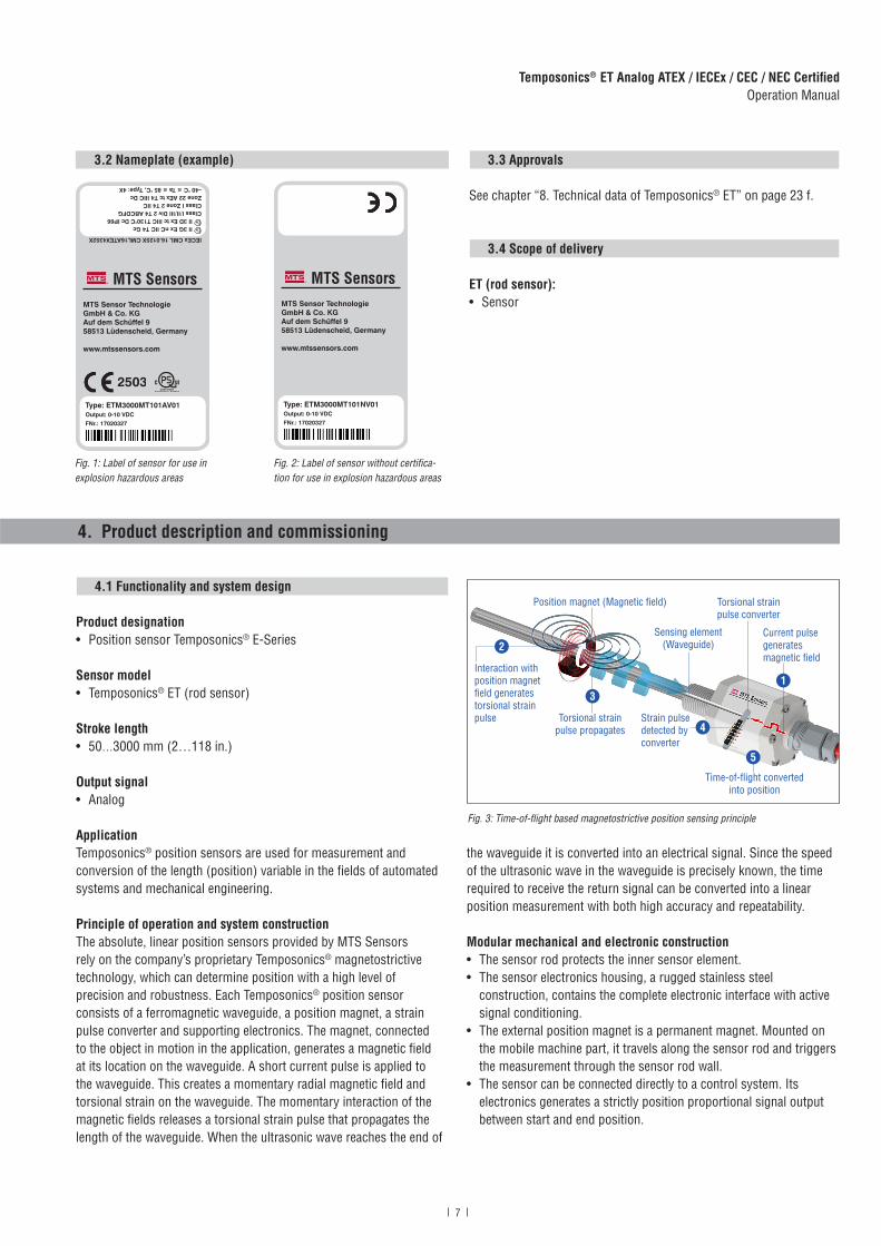
3.2 Nameplate (example) 3.3 Approvals
See chapter “8. Technical data of Temposonics® ET” on page 23 f.
3.4 Scope of delivery
ET (rod sensor):• Sensor
4.1 Functionality and system design
Product designation• Position sensor Temposonics® E-Series
Sensor model• Temposonics® ET (rod sensor)
Stroke length• 50…3000 mm (2…118 in.)
Output signal• Analog
ApplicationTemposonics® position sensors are used for measurement and conversion of the length (position) variable in the fields of automated systems and mechanical engineering.
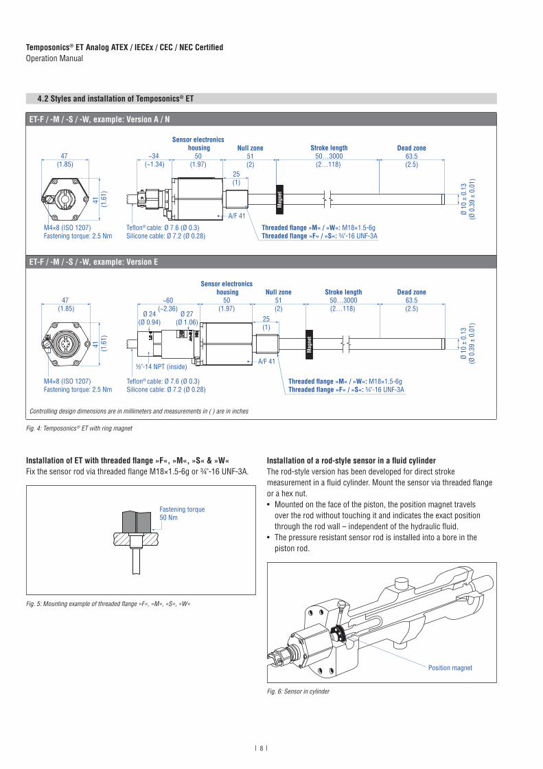
Principle of operation and system constructionThe absolute, linear position sensors provided by MTS Sensorsrely on the company’s proprietary Temposonics® magnetostrictivetechnology, which can determine position with a high level ofprecision and robustness. Each Temposonics® position sensorconsists of a ferromagnetic waveguide, a position magnet, a strainpulse converter and supporting electronics. The magnet, connectedto the object in motion in the application, generates a magnetic fieldat its location on the waveguide. A short current pulse is applied tothe waveguide. This creates a momentary radial magnetic field andtorsional strain on the waveguide. The momentary interaction of themagnetic fields releases a torsional strain pulse that propagates thelength of the waveguide. When the ultrasonic wave reaches the end of
4. Product description and commissioning
the waveguide it is converted into an electrical signal. Since the speedof the ultrasonic wave in the waveguide is precisely known, the timerequired to receive the return signal can be converted into a linearposition measurement with both high accuracy and repeatability.
Modular mechanical and electronic construction• The sensor rod protects the inner sensor element.• The sensor electronics housing, a rugged stainless steel
construction, contains the complete electronic interface with active signal conditioning.
• The external position magnet is a permanent magnet. Mounted on the mobile machine part, it travels along the sensor rod and triggers the measurement through the sensor rod wall.
• The sensor can be connected directly to a control system. Its electronics generates a strictly position proportional signal output between start and end position.
Fig. 1: Label of sensor for use in explosion hazardous areas
Fig. 2: Label of sensor without certifica-tion for use in explosion hazardous areas
Fig. 3: Time-of-flight based magnetostrictive position sensing principle
5
Sensing element (Waveguide)
Position magnet (Magnetic fi eld) Torsional strain pulse converter
4
Current pulse generates magnetic fi eld
Interaction with position magnet fi eld generates torsional strainpulse Torsional strain
pulse propagatesStrain pulse detected by converter
Time-of-fl ight converted into position
1
2
3
MTS Sensor TechnologieGmbH & Co. KGAuf dem Schüffel 958513 Lüdenscheid, Germany
www.mtssensors.com
IECEx CML 16.0125X CML16ATEX4352X
II 3G Ex nC IIC T4 Gc II 3D Ex tc IIIC T130°C Dc IP66
Class I/II/III Div 2 T4 ABCDFGClass I Zone 2 T4 IICZone 22 AEx tc T4 IIIC Dc−40 °C ≤ Ta ≤ 85 °C, Type: 4X
Type: ETM3000MT101AV01Output: 0-10 VDC FNr.: 17020327
MTS Sensor TechnologieGmbH & Co. KGAuf dem Schüffel 958513 Lüdenscheid, Germany
www.mtssensors.com
Type: ETM3000MT101NV01Output: 0-10 VDC FNr.: 17020327
8
Temposonics® ET Analog ATEX / IECEx / CEC / NEC CertifiedOperation Manual
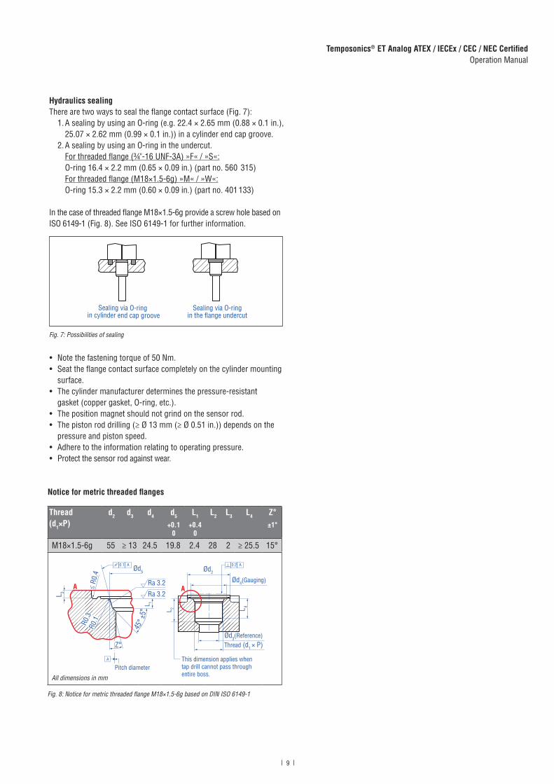
Fig. 4: Temposonics ® ET with ring magnet
4.2 Styles and installation of Temposonics® ET
Installation of ET with threaded flange »F«, »M«, »S« & »W«Fix the sensor rod via threaded flange M18×1.5-6g or ¾"-16 UNF-3A.
Fig. 5: Mounting example of threaded flange »F«, »M«, »S«, »W«
Installation of a rod-style sensor in a fluid cylinderThe rod-style version has been developed for direct stroke measurement in a fluid cylinder. Mount the sensor via threaded flange or a hex nut. • Mounted on the face of the piston, the position magnet travels
over the rod without touching it and indicates the exact position through the rod wall – independent of the hydraulic fluid.
• The pressure resistant sensor rod is installed into a bore in the piston rod.
Fig. 6: Sensor in cylinder
Fastening torque50 Nm
Position magnet
ET-F / -M / -S / -W, example: Version A / N
Threaded flange »M« / »W«: M18×1.5-6gThreaded flange »F« / »S«: ¾"-16 UNF-3A
Null zone51(2)
25(1)
Dead zone63.5(2.5)
Stroke length50…3000(2…118)
~34 (~1.34)
Sensor electronics housing
50(1.97)
Ø 10
± 0
.13
(Ø 0
.39
± 0.
01)
Teflon® cable: Ø 7.6 (Ø 0.3)Silicone cable: Ø 7.2 (Ø 0.28)
Mag
net
41
(1.6
1)
47 (1.85)
A/F 41
M4×8 (ISO 1207)Fastening torque: 2.5 Nm
ET-F / -M / -S / -W, example: Version E
Teflon® cable: Ø 7.6 (Ø 0.3)Silicone cable: Ø 7.2 (Ø 0.28)
Threaded flange »M« / »W«: M18×1.5-6gThreaded flange »F« / »S«: ¾"-16 UNF-3A
Ø 10
± 0
.13
(Ø 0
.39
± 0.
01)
41
(1.6
1)
47 (1.85)
M4×8 (ISO 1207)Fastening torque: 2.5 Nm
Mag
net
~60(~2.36)
Sensor electronics housing
50(1.97)
Null zone51(2)
A/F 41
Stroke length50…3000(2…118)
Dead zone63.5(2.5)
25(1)
½"-14 NPT (inside)
Ø 24(Ø 0.94)
Ø 27(Ø 1.06)
Controlling design dimensions are in millimeters and measurements in ( ) are in inches
9
Temposonics® ET Analog ATEX / IECEx / CEC / NEC CertifiedOperation Manual
Hydraulics sealingThere are two ways to seal the flange contact surface (Fig. 7):
1. A sealing by using an O-ring (e.g. 22.4 × 2.65 mm (0.88 × 0.1 in.), 25.07 × 2.62 mm (0.99 × 0.1 in.)) in a cylinder end cap groove.
2. A sealing by using an O-ring in the undercut. For threaded flange (¾"-16 UNF-3A) »F« / »S«: O-ring 16.4 × 2.2 mm (0.65 × 0.09 in.) (part no. 560 315) For threaded flange (M18×1.5-6g) »M« / »W«: O-ring 15.3 × 2.2 mm (0.60 × 0.09 in.) (part no. 401 133)
In the case of threaded flange M18×1.5-6g provide a screw hole based on ISO 6149-1 (Fig. 8). See ISO 6149-1 for further information.
Fig. 7: Possibilities of sealing
• Note the fastening torque of 50 Nm.• Seat the flange contact surface completely on the cylinder mounting
surface.• The cylinder manufacturer determines the pressure-resistant
gasket (copper gasket, O-ring, etc.).• The position magnet should not grind on the sensor rod.• The piston rod drilling (≥ Ø 13 mm (≥ Ø 0.51 in.)) depends on the
pressure and piston speed.• Adhere to the information relating to operating pressure.• Protect the sensor rod against wear.
Fig. 8: Notice for metric threaded flange M18×1.5-6g based on DIN ISO 6149-1
Thread (d1×P)
d2 d3 d4 d5
+0.10
L1
+0.40
L2 L3 L4 Z°±1°
M18×1.5-6g 55 ≥ 13 24.5 19.8 2.4 28 2 ≥ 25.5 15°
All dimensions in mm
Ød5
Ra 3.2
Ra 3.2
Pitch diameter
A
A
Thread (d1 × P)
Ød3(Reference)
A
Ød2
Ød4(Gauging)
This dimension applies when tap drill cannot pass throughentire boss.
≤ R0
.4
R0.3
R0.1
Z°
45° ±
5°
L 3
L 1
L 2 L 4
A0.1 A0.2
Notice for metric threaded flanges
Sealing via O-ringin the flange undercut
Sealing via O-ring in cylinder end cap groove
10
Temposonics® ET Analog ATEX / IECEx / CEC / NEC CertifiedOperation Manual
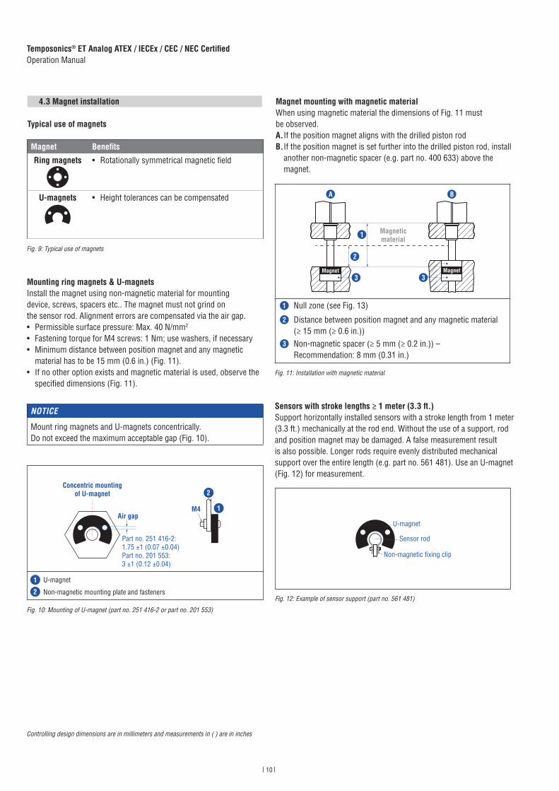
Sensors with stroke lengths ≥ 1 meter (3.3 ft.) Support horizontally installed sensors with a stroke length from 1 meter (3.3 ft.) mechanically at the rod end. Without the use of a support, rod and posi tion magnet may be damaged. A false measurement result is also possi ble. Longer rods require evenly distributed mechanical support over the entire length (e.g. part no. 561 481). Use an U-magnet (Fig. 12) for measurement.
Fig. 12: Example of sensor support (part no. 561 481)
Magnet mounting with magnetic materialWhen using magnetic material the dimensions of Fig. 11 must be observed.A. If the position magnet aligns with the drilled piston rodB. If the position magnet is set further into the drilled piston rod, install
another non-magnetic spacer (e.g. part no. 400 633) above the magnet.
Fig. 11: Installation with magnetic material
4.3 Magnet installation
Typical use of magnets
Mounting ring magnets & U-magnetsInstall the magnet using non-magnetic material for mounting device, screws, spacers etc.. The magnet must not grind on the sensor rod. Alignment errors are compensated via the air gap.• Permissible surface pressure: Max. 40 N/mm2
• Fastening torque for M4 screws: 1 Nm; use washers, if necessary• Minimum distance between position magnet and any magnetic
material has to be 15 mm (0.6 in.) (Fig. 11). • If no other option exists and magnetic material is used, observe the
specified dimensions (Fig. 11).
Magnet Benefits
Ring magnets • Rotationally symmetrical magnetic field
U-magnets • Height tolerances can be compensated
Fig. 9: Typical use of magnets
NOTICE
Mount ring magnets and U-magnets concentrically.Do not exceed the maximum acceptable gap (Fig. 10).
Fig. 10: Mounting of U-magnet (part no. 251 416-2 or part no. 201 553)
Controlling design dimensions are in millimeters and measurements in ( ) are in inches
U-magnet
Sensor rod
Non-magnetic fixing clip
Magneticmaterial
Magnet Magnet
1
2
3 3
A B
1 Null zone (see Fig. 13)
2 Distance between position magnet and any magnetic material (≥ 15 mm (≥ 0.6 in.))
3 Non-magnetic spacer (≥ 5 mm (≥ 0.2 in.)) – Recommendation: 8 mm (0.31 in.)
M4 1
2
Air gap
Concentric mountingof U-magnet
Part no. 201 553:3 ±1 (0.12 ±0.04)
Part no. 251 416-2:1.75 ±1 (0.07 ±0.04)
U-magnet
Non-magnetic mounting plate and fasteners
1
2

11
Temposonics® ET Analog ATEX / IECEx / CEC / NEC CertifiedOperation Manual
Start and end positions of the position magnetsConsider the start and end positions of the position magnets during the installation. To ensure that the entire stroke length is electrically usable, the position magnet must be mechanically mounted as follows.
NOTICE
On all sensors, the areas left and right of the active stroke length are provided for null and dead zone (see “4.2 Styles and installation of Temposonics® ET” on page 8). These zones should not be used for measurement, however the active stroke length can be exceeded.
Controlling design dimensions are in millimeters and measurements in ( ) are in inches
Fig. 13: Start and end positions of magnets
Multi-position measurementThe minimum distance between the magnets is 75 mm (3 in.).
NOTICE
Use magnets of the same type (e.g. two ring magnets with part no. 201 542-2) for multi-position measurement.
Fig. 14: Minimum distance for multi-position measurement
ET with ring magnet & U-magnet
Reference edge of mounting
Start position51 (2)
End position63.5 (2.5)
Active measuring range
ET with ring magnet & U-magnet
≥ 75 (≥ 3)

12
Temposonics® ET Analog ATEX / IECEx / CEC / NEC CertifiedOperation Manual
4.4 Electrical connection
Placement of installation and cabling have decisive influence on thesensor‘s electromagnetic compatibility (EMC). Hence correct installation of this active electronic system and the EMC of the entire system must be ensured by using suitable metal connectors, shielded cables and grounding. Overvoltages or faulty connections can damage the sensor electronics despite protection against wrong polarity.
NOTICE
1. Do not mount the sensors in the area of strong magnetic or electric noise fields.
2. Never connect / disconnect the sensor when voltage is applied.
Instruction for connection• Connect the shield to ground externally via the controller equipment. • Keep control and signal leads separate from power cables and
sufficiently far away from motor cables, frequency inverters, valve lines, relays, etc..
• Use only connectors with metal housing, if you use a connector. Connect the shielding to the connector housing.
• Keep all non-shielded leads as short as possible. • Keep the earth connection as short as possible with a large cross
section. Avoid ground loops. • With potential differences between machine and electronics
earth connections, no compensating currents are allowed to flow across the cable shielding. Recommendation: Install potential compensating leads with large cross section.
• Use only stabilized power supplies in compliance with the specified electrical ratings.
Grounding of rod sensorsConnect the sensor electronics housing to machine ground. Ground sensor type ET version A (with ATEX / IECEx / CEC / NEC approval) via ground lug as shown in Fig. 15. Ground the sensor type ET version N (not approved) via ground lug as shown in Fig. 15 or via thread. Ground sensor type ET version E (with ATEX / IECEx / CEC / NEC approval) via ground lug as shown in Fig. 16.
Connector wiringConnect the sensor directly to the controller, indicator or other evaluating systems as follows:
TXX / VXX
Signal + power supply
Cable Color Voltage Current
GY Output 1:0…10 VDC or10…0 VDC
Output 1:4(0)…20 mA or 20… 4(0) mA
PK DC Groundfor output 1
DC Groundfor output 1
YE Output 2:0…10 VDC or10…0 VDC
Output 2:4(0)…20 mA or 20… 4(0) mA
GN DC Groundfor output 2
DC Groundfor output 2
BN +24 VDC (−15 / +20 %)
+24 VDC (−15 / +20 %)
WH DC Ground (0 V) DC Ground (0 V)
Fig. 15: Grounding via ground lug (version A, N)
Fig. 16: Grounding via ground lug (version E)
Fig. 17: Connector wiring TXX / VXX
13
Temposonics® ET Analog ATEX / IECEx / CEC / NEC CertifiedOperation Manual
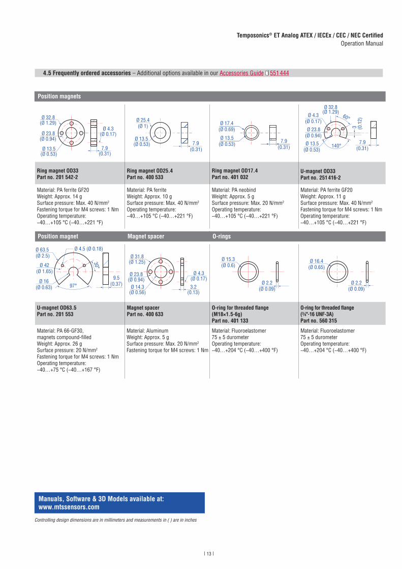
4.5 Frequently ordered accessories
Position magnets
Ø 32.8(Ø 1.29)
Ø 23.8(Ø 0.94)
Ø 13.5(Ø 0.53)
Ø 4.3(Ø 0.17)
7.9(0.31)
Ø 25.4(Ø 1)
Ø 13.5(Ø 0.53) 7.9
(0.31)
Ø 13.5(Ø 0.53)
Ø 17.4(Ø 0.69)
7.9(0.31)
Ø 32.8(Ø 1.29)
Ø 23.8(Ø 0.94)
Ø 13.5(Ø 0.53)
Ø 4.3(Ø 0.17)
60°
140°
3 (0.1
2)
7.9(0.31)
Ring magnet OD33Part no. 201 542-2
Ring magnet OD25.4Part no. 400 533
Ring magnet OD17.4Part no. 401 032
U-magnet OD33Part no. 251 416-2
Material: PA ferrite GF20Weight: Approx. 14 gSurface pressure: Max. 40 N/mm2
Fastening torque for M4 screws: 1 NmOperating temperature: −40…+105 °C (−40…+221 °F)
Material: PA ferriteWeight: Approx. 10 gSurface pressure: Max. 40 N/mm2
Operating temperature: −40…+105 °C (−40…+221 °F)
Material: PA neobindWeight: Approx. 5 gSurface pressure: Max. 20 N/mm2
Operating temperature: −40…+105 °C (−40…+221 °F)
Material: PA ferrite GF20Weight: Approx. 11 gSurface pressure: Max. 40 N/mm2
Fastening torque for M4 screws: 1 NmOperating temperature: −40…+105 °C (−40…+221 °F)
Position magnet Magnet spacer O-rings
Ø 4.5 (Ø 0.18)Ø 63.5(Ø 2.5)
Ø 42(Ø 1.65)
Ø 16(Ø 0.63) 97°
30°
9.5(0.37) Ø 14.3
(Ø 0.56)
Ø 23.8(Ø 0.94)
Ø 31.8(Ø 1.25)
Ø 4.3(Ø 0.17)
3.2(0.13)
Ø 15.3(Ø 0.6)
Ø 2.2(Ø 0.09)
Ø 16.4(Ø 0.65)
Ø 2.2(Ø 0.09)
U-magnet OD63.5Part no. 201 553
Magnet spacerPart no. 400 633
O-ring for threaded fl ange (M18×1.5-6g)Part no. 401 133
O-ring for threaded fl ange (¾"-16 UNF-3A)Part no. 560 315
Material: PA 66-GF30, magnets compound-fi lledWeight: Approx. 26 gSurface pressure: 20 N/mm2
Fastening torque for M4 screws: 1 NmOperating temperature:−40…+75 °C (−40…+167 °F)
Material: Aluminum Weight: Approx. 5 gSurface pressure: Max. 20 N/mm2
Fastening torque for M4 screws: 1 Nm
Material: Fluoroelastomer 75 ± 5 durometerOperating temperature:−40…+204 °C (−40…+400 °F)
Material: Fluoroelastomer 75 ± 5 durometer Operating temperature:−40…+204 °C (−40…+400 °F)
– Additional options available in our Accessories Guide 551 444
Controlling design dimensions are in millimeters and measurements in ( ) are in inches
Manuals, Software & 3D Models available at: www.mtssensors.com
14
Temposonics® ET Analog ATEX / IECEx / CEC / NEC CertifiedOperation Manual
Controlling design dimensions are in millimeters and measurements in ( ) are in inches
Manuals, Software & 3D Models available at: www.mtssensors.com
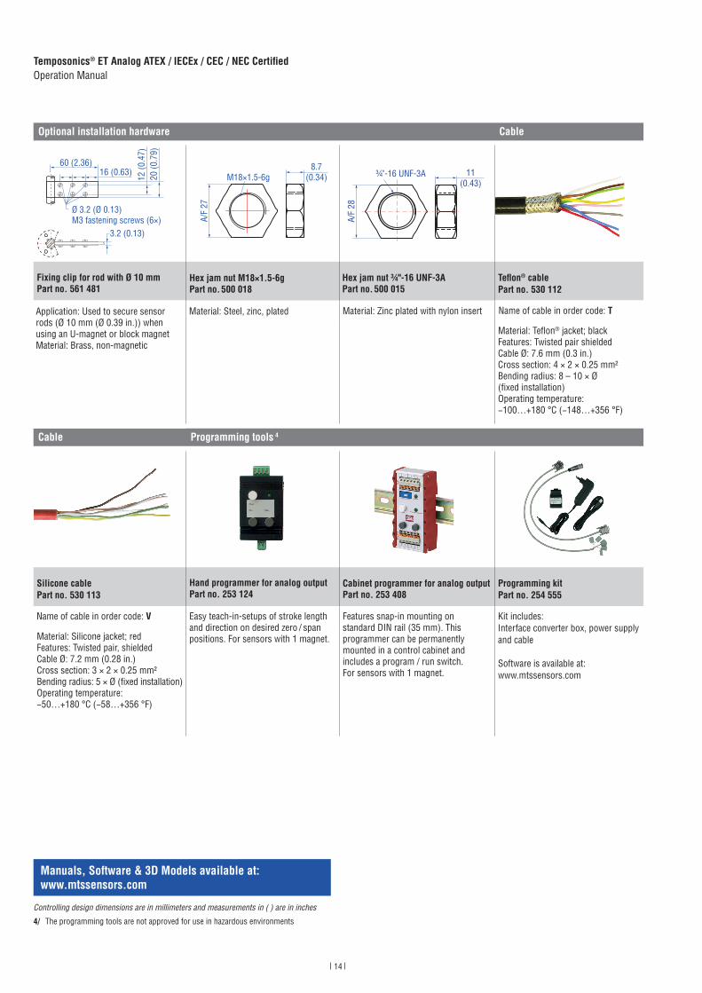
Optional installation hardware Cable
20 (0
.79)
60 (2.36)16 (0.63)
12 (0
.47)
3.2 (0.13)
Ø 3.2 (Ø 0.13)M3 fastening screws (6×)
M18×1.5-6g
A/F
27
8.7(0.34) ¾"-16 UNF-3A
A/F
28
11(0.43)
Fixing clip for rod with Ø 10 mmPart no. 561 481
Hex jam nut M18×1.5-6gPart no. 500 018
Hex jam nut ¾"-16 UNF-3APart no. 500 015
Tefl on® cablePart no. 530 112
Application: Used to secure sensor rods (Ø 10 mm (Ø 0.39 in.)) when using an U-magnet or block magnetMaterial: Brass, non-magnetic
Material: Steel, zinc, plated Material: Zinc plated with nylon insert Name of cable in order code: T
Material: Tefl on® jacket; blackFeatures: Twisted pair shieldedCable Ø: 7.6 mm (0.3 in.)Cross section: 4 × 2 × 0.25 mm²Bending radius: 8 – 10 × Ø (fi xed installation)Operating temperature: −100…+180 °C (−148…+356 °F)
Cable Programming tools 4
Silicone cablePart no. 530 113
Hand programmer for analog outputPart no. 253 124
Cabinet programmer for analog outputPart no. 253 408
Programming kitPart no. 254 555
Name of cable in order code: V Easy teach-in-setups of stroke lengthand direction on desired zero / spanpositions. For sensors with 1 magnet.
Features snap-in mounting on standard DIN rail (35 mm). This programmer can be permanently mounted in a control cabinet and includes a program / run switch. For sensors with 1 magnet.
Kit includes:Interface converter box, power supply and cable
Software is available at:www.mtssensors.com
Material: Silicone jacket; redFeatures: Twisted pair, shieldedCable Ø: 7.2 mm (0.28 in.)Cross section: 3 × 2 × 0.25 mm²Bending radius: 5 × Ø (fi xed installation)Operating temperature: −50…+180 °C (−58…+356 °F)
4/ The programming tools are not approved for use in hazardous environments
15
Temposonics® ET Analog ATEX / IECEx / CEC / NEC CertifiedOperation Manual
5. Operation
5.1 Getting started
The sensor is factory-set to its order sizes and adjusted, i.e. therequired output signal corresponds exactly to the selected strokelength.Example: Output 4…20 mA = 0…100 % stroke length
NOTICE If necessary, the analog sensors can be re-adjusted using the service tools described below.
5.2 Programming and configuration
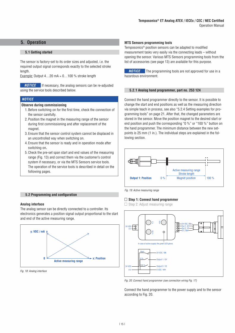
Analog interfaceThe analog sensor can be directly connected to a controller. Its electronics generates a position signal output proportional to the start and end of the active measuring range.
Step 1: Connect hand programmerStep 2: Adjust measuring range
Fig. 18: Analog interface
Fig. 19: Active measuring range
Fig. 20: Connect hand programmer (see connection wiring Fig. 17)
MTS Sensors programming toolsTemposonics® position sensors can be adapted to modified measurement tasks very easily via the connecting leads – without opening the sensor. Various MTS Sensors programming tools from the list of accessories (see page 13) are available for this purpose.
NOTICE The programming tools are not approved for use in a hazardous environment.
5.2.1 Analog hand programmer, part no. 253 124
Connect the hand programmer directly to the sensor. It is possible to change the start and end positions as well as the measuring direction via simple teach in process, see also “5.2.4 Setting examples for pro-gramming tools” on page 21. After that, the changed parameters are stored in the sensor. Move the position magnet to the desired start or end position and push the corresponding “0 %” or “100 %” button on the hand programmer. The minimum distance between the new set-points is 25 mm (1 in.). The individual steps are explained in the fol-lowing section.
Connect the hand programmer to the power supply and to the sensor according to Fig. 20.
NOTICE
Observe during commissioning 1. Before switching on for the first time, check the connection of
the sensor carefully. 2. Position the magnet in the measuring range of the sensor
during first commissioning and after replacement of the magnet.
3. Ensure that the sensor control system cannot be displaced in an uncontrolled way when switching on.
4. Ensure that the sensor is ready and in operation mode after switching on.
5. Check the pre-set span start and end values of the measuring range (Fig. 13) and correct them via the customer’s control system if necessary, or via the MTS Sensors service tools. The operation of the service tools is described in detail on the following pages. Active measuring range
Stroke length0 % 100 %Magnet positionOutput 1: Position
In case of active supply the green LED glows
Start
0 %100 %
24 VDC0 V
24 VDC / BN
Output 1 / GY
Output 2 / YE
0 VDC / WH
Start
0 %
100 %24 VDC
0 V
24 VDC, BN Out 1, GYOut 2, YE0 V, WH
x: Position0
y: VDC / mA
Active measuring range

16
Temposonics® ET Analog ATEX / IECEx / CEC / NEC CertifiedOperation Manual
NOTICE
You can only adapt magnet 1 via hand programmer. In order to change the settings of magnet 1 you have to connect both outputs (output 1 and output 2).
Step 1: Connect hand programmerStep 2: Adjust measuring range
1. Activate programming mode:• Press “Start” button and “100 %” button simultaneously• Release “Start” button first, wait 1 second and release “100 %”
button
2. Set start position (0 % output) (Fig. 22): • Set the position magnet on start position• Press and release the “0 %” button
Fig. 21: Adjust measuring range
Fig. 22: Determine start and end position
3. Set end position (100 % output) (Fig. 22):• Set the position magnet on end position• Press and release the “100 %” button
4. Back to normal function (operation mode):• Press “Start” button• Connect the sensor to control unit
Start
0 % 100 %
24 VDC
Sensor
LED
Output 1 Output 2
Output from order code
Start posi-tion (0 % output)
End positi-on (100 % output)
Start posi-tion (0 % output)
End positi-on (100 % output)
V01 0 VDC 10 VDC — —
V11 10 VDC 0 VDC — —
V03 0 VDC 10 VDC 10 VDC 0 VDC
V02 0 VDC 10 VDC 0 VDC * 10 VDC *
V12 10 VDC 0 VDC 10 VDC * 0 VDC *
A01 4 mA 20 mA — —
A11 20 mA 4 mA — —
A03 4 mA 20 mA 20 mA 4 mA
A02 4 mA 20 mA 4 mA * 20 mA *
A12 20 mA 4 mA 20 mA * 4 mA *
* When using the analog hand programmer only the start and end positions of magnet 1 (output 1) are adjusted. The settings of magnet 2 (output 2) are not affected.
17
Temposonics® ET Analog ATEX / IECEx / CEC / NEC CertifiedOperation Manual
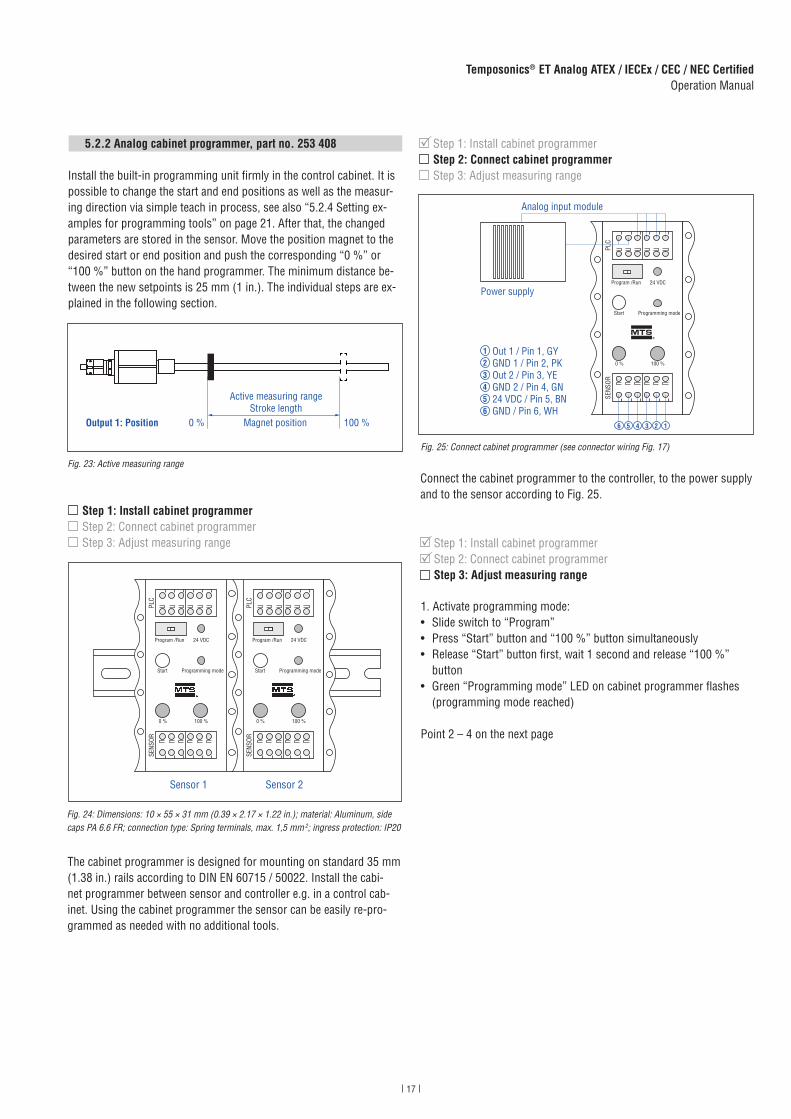
5.2.2 Analog cabinet programmer, part no. 253 408
Install the built-in programming unit firmly in the control cabinet. It is possible to change the start and end positions as well as the measur-ing direction via simple teach in process, see also “5.2.4 Setting ex-amples for programming tools” on page 21. After that, the changed parameters are stored in the sensor. Move the position magnet to the desired start or end position and push the corresponding “0 %” or “100 %” button on the hand programmer. The minimum distance be-tween the new setpoints is 25 mm (1 in.). The individual steps are ex-plained in the following section.
Fig. 23: Active measuring range
The cabinet programmer is designed for mounting on standard 35 mm (1.38 in.) rails according to DIN EN 60715 / 50022. Install the cabi-net programmer between sensor and controller e.g. in a control cab-inet. Using the cabinet programmer the sensor can be easily re-pro-grammed as needed with no additional tools.
Step 1: Install cabinet programmerStep 2: Connect cabinet programmerStep 3: Adjust measuring range
Fig. 24: Dimensions: 10 × 55 × 31 mm (0.39 × 2.17 × 1.22 in.); material: Aluminum, side caps PA 6.6 FR; connection type: Spring terminals, max. 1,5 mm 2; ingress protection: IP20
Step 1: Install cabinet programmerStep 2: Connect cabinet programmerStep 3: Adjust measuring range
Connect the cabinet programmer to the controller, to the power supply and to the sensor according to Fig. 25.
Fig. 25: Connect cabinet programmer (see connector wiring Fig. 17)
1. Activate programming mode:• Slide switch to “Program”• Press “Start” button and “100 %” button simultaneously• Release “Start” button first, wait 1 second and release “100 %”
button• Green “Programming mode” LED on cabinet programmer flashes
(programming mode reached)
Point 2 – 4 on the next page
Step 1: Install cabinet programmerStep 2: Connect cabinet programmerStep 3: Adjust measuring range
Active measuring rangeStroke length
0 % 100 %Magnet positionOutput 1: Position
Sensor 1 Sensor 2
PLC
SENS
OR
Program /Run
Start
0 % 100 %
Programming mode
24 VDC
PLC
SENS
OR
Program /Run
Start
0 % 100 %
Programming mode
24 VDC
PLC
SENS
OR
Program /Run
Start
0 % 100 %
Programming mode
24 VDC
Out 1 / Pin 1, GYGND 1 / Pin 2, PKOut 2 / Pin 3, YEGND 2 / Pin 4, GN24 VDC / Pin 5, BNGND / Pin 6, WH
123456
123456
Analog input module
Power supply
18
Temposonics® ET Analog ATEX / IECEx / CEC / NEC CertifiedOperation Manual
Fig. 26: Determine start and end position
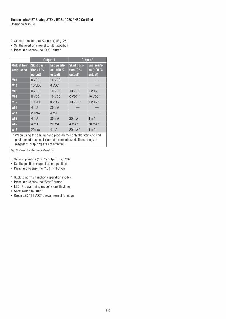
2. Set start position (0 % output) (Fig. 26):• Set the position magnet to start position• Press and release the “0 %” button
3. Set end position (100 % output) (Fig. 26):• Set the position magnet to end position• Press and release the “100 %” button
4. Back to normal function (operation mode):• Press and release the “Start” button• LED “Programming mode” stops flashing• Slide switch to “Run”• Green LED “24 VDC” shows normal function
Output 1 Output 2
Output from order code
Start posi-tion (0 % output)
End positi-on (100 % output)
Start posi-tion (0 % output)
End positi-on (100 % output)
V01 0 VDC 10 VDC — —
V11 10 VDC 0 VDC — —
V03 0 VDC 10 VDC 10 VDC 0 VDC
V02 0 VDC 10 VDC 0 VDC * 10 VDC *
V12 10 VDC 0 VDC 10 VDC * 0 VDC *
A01 4 mA 20 mA — —
A11 20 mA 4 mA — —
A03 4 mA 20 mA 20 mA 4 mA
A02 4 mA 20 mA 4 mA * 20 mA *
A12 20 mA 4 mA 20 mA * 4 mA *
* When using the analog hand programmer only the start and end positions of magnet 1 (output 1) are adjusted. The settings of magnet 2 (output 2) are not affected.
19
Temposonics® ET Analog ATEX / IECEx / CEC / NEC CertifiedOperation Manual
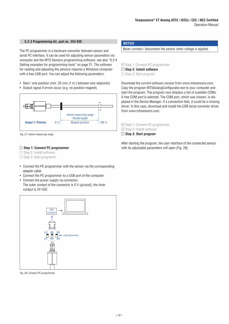
5.2.3 Programming kit, part no. 254 555
The PC programmer is a hardware converter between sensor and serial PC interface. It can be used for adjusting sensor parameters via computer and the MTS Sensors programming software, see also “5.2.4 Setting examples for programming tools” on page 21. The software for reading and adjusting the sensors requires a Windows computer with a free USB port. You can adjust the following parameters:
• Start / end position (min. 25 mm (1 in.) between new setpoints)• Output signal if errors occur (e.g. no position magnet)
Fig. 27: Active measuring range
Fig. 28: Connect PC programmer
Step 1: Connect PC programmerStep 2: Install softwareStep 3: Start programm
• Connect the PC programmer with the sensor via the corresponding adapter cable
• Connect the PC programmer to a USB port of the computer• Connect the power supply via connector
The outer contact of the connector is 0 V (ground), the inner contact is 24 VDC
NOTICE
Never connect / disconnect the sensor when voltage is applied.
Download the current software version from www.mtssensors.com. Copy the program MTSAnalogConfigurator.exe to your computer and start the program. The program now displays a list of available COMs. A free COM port is selected. The COM port, which was chosen, is dis-played in the Device Manager. If a connection fails, it could be a missing driver. In this case, download and install the USB serial converter driver from www.mtssensors.com.
After starting the program, the user interface of the connected sensor with its adjustable parameters will open (Fig. 29).
Step 1: Connect PC programmerStep 2: Install softwareStep 3: Start program
Step 1: Connect PC programmerStep 2: Install software Step 3: Start program
Active measuring rangeStroke length
0 % 100 %Magnet positionOutput 1: Position
GY WH BN
WH BNGY
USB converter
Spring terminal
20
Temposonics® ET Analog ATEX / IECEx / CEC / NEC CertifiedOperation Manual
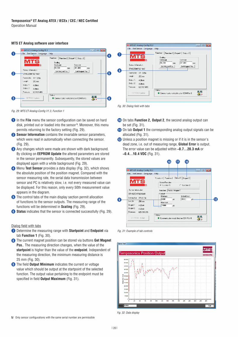
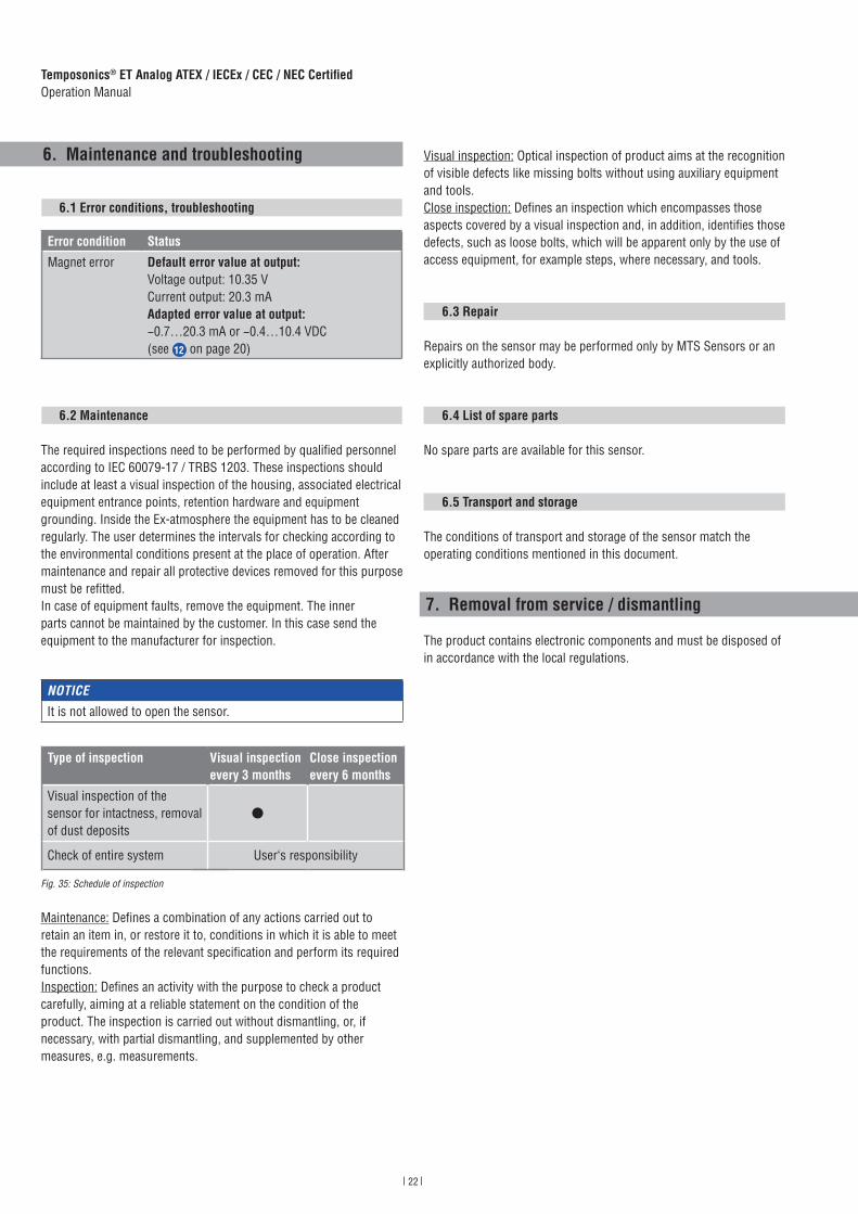
In the File menu the sensor configuration can be saved on hard disk, printed out or loaded into the sensor 5. Moreover, this menu permits returning to the factory setting (Fig. 29).Sensor Information contains the invariable sensor parameters, which were read in automatically when connecting the sensor. (Fig. 29).Any changes which were made are shown with dark background. By clicking on EEPROM Update the altered parameters are stored in the sensor permanently. Subsequently, the stored values are displayed again with a white background (Fig. 29).Menu Test Sensor provides a data display (Fig. 32), which shows the absolute position of the position magnet. Compared with the sensor measuring rate, the serial data transmission between sensor and PC is relatively slow, i.e. not every measured value can be displayed. For this reason, only every 50th measurement value appears in the diagram. The control tabs of the main display section permit allocation of functions to the sensor outputs. The measuring range of the functions will be determined in Scaling (Fig. 29).Status indicates that the sensor is connected successfully (Fig. 29).
Dialog field with tabs
Determine the measuring range with Startpoint and Endpoint via tab Function 1 (Fig. 30).The current magnet position can be stored via buttons Get Magnet Pos.. The measuring direction changes, when the value of the startpoint is higher than the value of the endpoint. Independent of the measuring direction, the minimum measuring distance is 25 mm (Fig. 30). The field Output Minimum indicates the current or voltage value which should be output at the startpoint of the selected function. The output value pertaining to the endpoint must be specified in field Output Maximum (Fig. 31).
Fig. 29: MTS ET-Analog-Config V1.3, Function 1
Fig. 30: Dialog field with tabs
On tabs Function 2, Output 2, the second analog output can be set (Fig. 31).On tab Output 1 the corresponding analog output signals can be allocated (Fig. 31).Unless a position magnet is missing or if it is in the sensor's dead zone, i.e. out of measuring range, Global Error is output. The error value can be adjusted within −0.7…20.3 mA or−0.4…10.4 VDC (Fig. 31).
Fig. 31: Example of tab controls
5/ Only sensor configurations with the same serial number are permissible
MTS ET Analog software user interface
1
2
3
4
5
6
7
8
9
10
12
11
1
2
3
5
6
7
8
10 11 10
129
4
Fig. 32: Data display

21
Temposonics® ET Analog ATEX / IECEx / CEC / NEC CertifiedOperation Manual
5.2.4 Setting examples for programming tools
The sensor‘s measuring range can be repositioned using the tools described above at any time.
NOTICE
Independent of the measuring direction, the location of the setpoints in the factory settings is always: SP1 (set point 1) at sensor electronics housing and SP2 (set point 2) at rod end. (Fig. 33).
Fig. 33: Adjust start and end position
Fig. 34: Start and end position, adjustment / reversal of measuring direction
0 %SP1
100 %SP2
20 mA20.3 mA (1)
20 mA20.3 mA (1)
4 mA
4 mA
0 %SP1
100 %SP2
Factory setupOutput: 4…20 mA
New field settingOutput: 4…20 mA
(1) Default error value
Active measuring range
0 %SP1
100 %SP2
20 mA20.3 mA (1)
4 mA
20.3 mA (1)
4 mA
20 mA
0 %SP1
100 %SP2
Factory setupOutput: 4…20 mA
New field settingOutput: 20…4 mA
(1) Default error value
Active measuring range
22
Temposonics® ET Analog ATEX / IECEx / CEC / NEC CertifiedOperation Manual
6. Maintenance and troubleshooting
6.1 Error conditions, troubleshooting
6.2 Maintenance
The required inspections need to be performed by qualified personnel according to IEC 60079-17 / TRBS 1203. These inspections shouldinclude at least a visual inspection of the housing, associated electricalequipment entrance points, retention hardware and equipmentgrounding. Inside the Ex-atmosphere the equipment has to be cleaned regularly. The user determines the intervals for checking according to the environmental conditions present at the place of operation. After maintenance and repair all protective devices removed for this purpose must be refitted. In case of equipment faults, remove the equipment. The inner parts cannot be maintained by the customer. In this case send the equipment to the manufacturer for inspection.
Maintenance: Defines a combination of any actions carried out to retain an item in, or restore it to, conditions in which it is able to meet the requirements of the relevant specification and perform its required functions.Inspection: Defines an activity with the purpose to check a product carefully, aiming at a reliable statement on the condition of the product. The inspection is carried out without dismantling, or, if necessary, with partial dismantling, and supplemented by other measures, e.g. measurements.
Visual inspection: Optical inspection of product aims at the recognition of visible defects like missing bolts without using auxiliary equipment and tools.Close inspection: Defines an inspection which encompasses those aspects covered by a visual inspection and, in addition, identifies those defects, such as loose bolts, which will be apparent only by the use of access equipment, for example steps, where necessary, and tools.
6.3 Repair
Repairs on the sensor may be performed only by MTS Sensors or an explicitly authorized body.
6.4 List of spare parts
No spare parts are available for this sensor.
6.5 Transport and storage
The conditions of transport and storage of the sensor match the operating conditions mentioned in this document.
7. Removal from service / dismantling
The product contains electronic components and must be disposed of in accordance with the local regulations.
NOTICE
It is not allowed to open the sensor.
Fig. 35: Schedule of inspection
Type of inspection Visual inspectionevery 3 months
Close inspectionevery 6 months
Visual inspection of the sensor for intactness, removal of dust deposits
Check of entire system User‘s responsibility
Error condition Status
Magnet error Default error value at output:Voltage output: 10.35 VCurrent output: 20.3 mAAdapted error value at output:−0.7…20.3 mA or −0.4…10.4 VDC(see 12 on page 20)
23
Temposonics® ET Analog ATEX / IECEx / CEC / NEC CertifiedOperation Manual
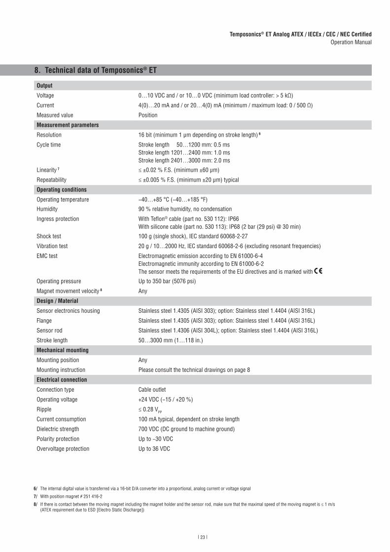
8. Technical data of Temposonics® ET
Output
Voltage 0…10 VDC and / or 10…0 VDC (minimum load controller: > 5 kΩ)
Current 4(0)…20 mA and / or 20…4(0) mA (minimum / maximum load: 0 / 500 Ω)
Measured value Position
Measurement parameters
Resolution 16 bit (minimum 1 μm depending on stroke length) 6
Cycle time Stroke length 50…1200 mm: 0.5 msStroke length 1201…2400 mm: 1.0 msStroke length 2401…3000 mm: 2.0 ms
Linearity 7 ≤ ±0.02 % F.S. (minimum ±60 μm)
Repeatability ≤ ±0.005 % F.S. (minimum ±20 μm) typical
Operating conditions
Operating temperature −40…+85 °C (−40…+185 °F)
Humidity 90 % relative humidity, no condensation
Ingress protection With Teflon® cable (part no. 530 112): IP66With silicone cable (part no. 530 113): IP68 (2 bar (29 psi) @ 30 min)
Shock test 100 g (single shock), IEC standard 60068-2-27
Vibration test 20 g / 10…2000 Hz, IEC standard 60068-2-6 (excluding resonant frequencies)
EMC test Electromagnetic emission according to EN 61000-6-4Electromagnetic immunity according to EN 61000-6-2The sensor meets the requirements of the EU directives and is marked with
Operating pressure Up to 350 bar (5076 psi)
Magnet movement velocity 8 Any
Design / Material
Sensor electronics housing Stainless steel 1.4305 (AISI 303); option: Stainless steel 1.4404 (AISI 316L)
Flange Stainless steel 1.4305 (AISI 303); option: Stainless steel 1.4404 (AISI 316L)
Sensor rod Stainless steel 1.4306 (AISI 304L); option: Stainless steel 1.4404 (AISI 316L)
Stroke length 50…3000 mm (1…118 in.)
Mechanical mounting
Mounting position Any
Mounting instruction Please consult the technical drawings on page 8
Electrical connection
Connection type Cable outlet
Operating voltage +24 VDC (−15 / +20 %)
Ripple ≤ 0.28 VPP
Current consumption 100 mA typical, dependent on stroke length
Dielectric strength 700 VDC (DC ground to machine ground)
Polarity protection Up to −30 VDC
Overvoltage protection Up to 36 VDC
6/ The internal digital value is transferred via a 16-bit D/A converter into a proportional, analog current or voltage signal
7/ With position magnet # 251 416-2
8/ If there is contact between the moving magnet including the magnet holder and the sensor rod, make sure that the maximal speed of the moving magnet is ≤ 1 m/s (ATEX requirement due to ESD [Electro Static Discharge])
24
Temposonics® ET Analog ATEX / IECEx / CEC / NEC CertifiedOperation Manual
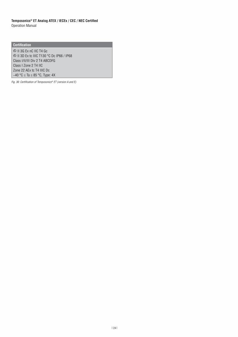
Fig. 36: Certification of Temposonics® ET (version A and E)
Certifi cation
II 3G Ex nC IIC T4 Gc II 3D Ex tc IIIC T130 °C Dc IP66 / IP68
Class I/II/III Div 2 T4 ABCDFGClass I Zone 2 T4 IICZone 22 AEx tc T4 IIIC Dc−40 °C ≤ Ta ≤ 85 °C, Type: 4X
25
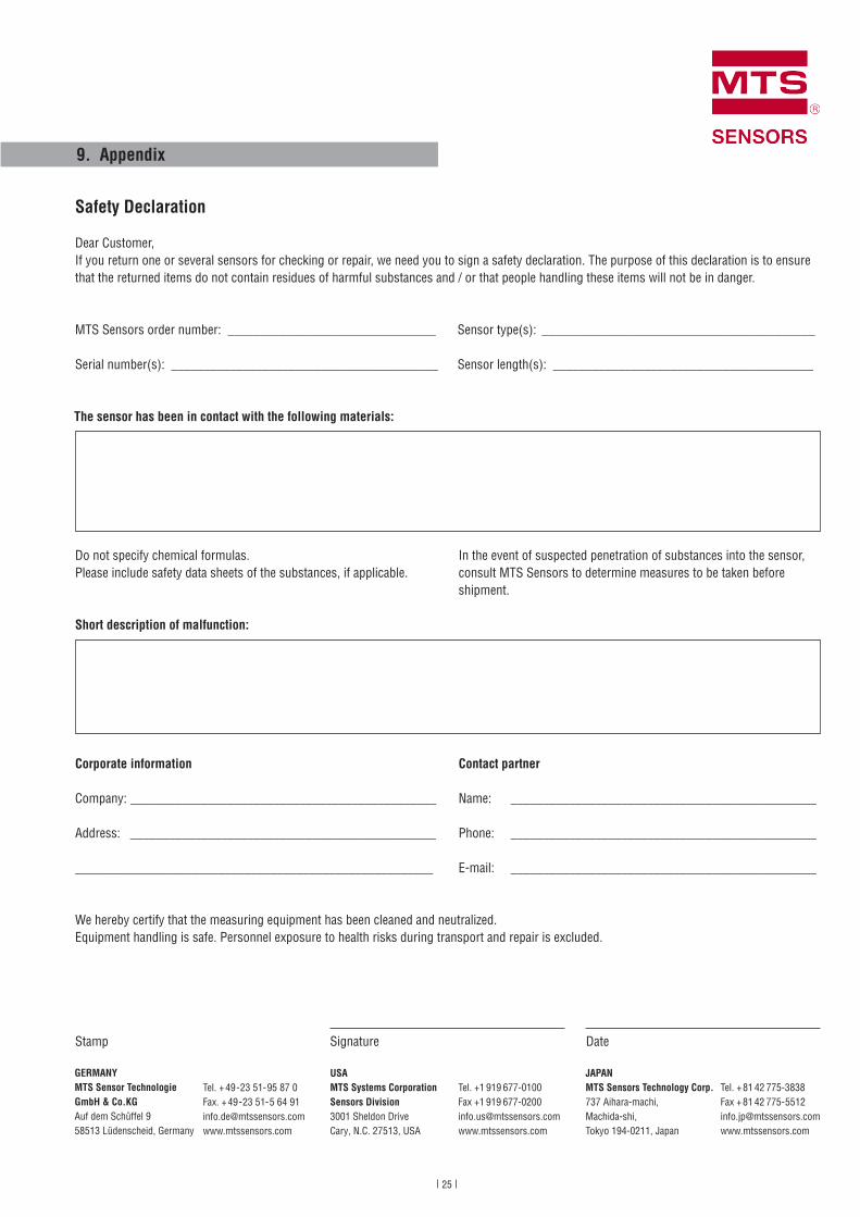
9. Appendix
Safety Declaration
Dear Customer,If you return one or several sensors for checking or repair, we need you to sign a safety declaration. The purpose of this declaration is to ensure that the returned items do not contain residues of harmful substances and / or that people handling these items will not be in danger.
MTS Sensors order number: ________________________________
Serial number(s): _________________________________________
Sensor type(s): __________________________________________
Sensor length(s): ________________________________________
The sensor has been in contact with the following materials:
In the event of suspected penetration of substances into the sensor, consult MTS Sensors to determine measures to be taken before shipment.
Do not specify chemical formulas.Please include safety data sheets of the substances, if applicable.
Short description of malfunction:
Corporate information
Company: _______________________________________________
Address: _______________________________________________
_______________________________________________________
Contact partner
Name: _______________________________________________
Phone: _______________________________________________
E-mail: _______________________________________________
We hereby certify that the measuring equipment has been cleaned and neutralized. Equipment handling is safe. Personnel exposure to health risks during transport and repair is excluded.
DateSignatureStamp
Tel. + 49 - 23 51- 95 87 0Fax. + 49 - 23 51- 5 64 [email protected]
GERMANYMTS Sensor Technologie GmbH & Co.KG Auf dem Schüffel 9 58513 Lüdenscheid, Germany
USAMTS Systems CorporationSensors Division3001 Sheldon DriveCary, N.C. 27513, USA
Tel. +1 919 677-0100Fax +1 919 [email protected]
JAPANMTS Sensors Technology Corp.737 Aihara-machi, Machida-shi, Tokyo 194-0211, Japan
Tel. + 81 42 775-3838Fax + 81 42 775- [email protected]
26
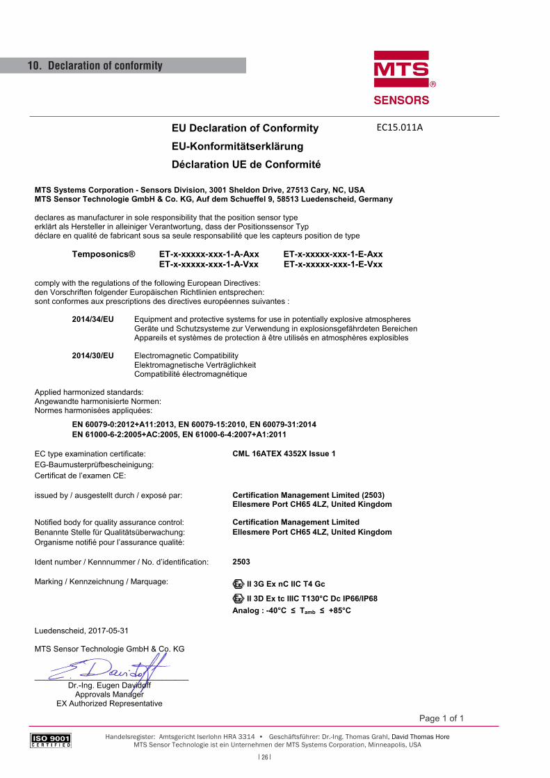
10. Declaration of conformity
Page 1 of 1
Handelsregister: Amtsgericht Iserlohn HRA 3314 • Geschäftsführer: Dr.-Ing. Thomas Grahl, David Thomas Hore MTS Sensor Technologie ist ein Unternehmen der MTS Systems Corporation, Minneapolis, USA
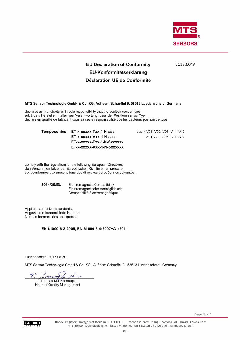
EU Declaration of ConformityEU-KonformitätserklärungDéclaration UE de Conformité
MTS Systems Corporation - Sensors Division, 3001 Sheldon Drive, 27513 Cary, NC, USAMTS Sensor Technologie GmbH & Co. KG, Auf dem Schueffel 9, 58513 Luedenscheid, Germany
declares as manufacturer in sole responsibility that the position sensor typeerklärt als Hersteller in alleiniger Verantwortung, dass der Positionssensor Typdéclare en qualité de fabricant sous sa seule responsabilité que les capteurs position de type
Temposonics® ET-x-xxxxx-xxx-1-A-Axx ET-x-xxxxx-xxx-1-E-AxxET-x-xxxxx-xxx-1-A-Vxx ET-x-xxxxx-xxx-1-E-Vxx
comply with the regulations of the following European Directives:den Vorschriften folgender Europäischen Richtlinien entsprechen:sont conformes aux prescriptions des directives européennes suivantes :
2014/34/EU Equipment and protective systems for use in potentially explosive atmospheresGeräte und Schutzsysteme zur Verwendung in explosionsgefährdeten BereichenAppareils et systèmes de protection à être utilisés en atmosphères explosibles
2014/30/EU Electromagnetic CompatibilityElektromagnetische VerträglichkeitCompatibilité électromagnétique
Applied harmonized standards:Angewandte harmonisierte Normen:Normes harmonisées appliquées:
EN 60079-0:2012+A11:2013, EN 60079-15:2010, EN 60079-31:2014EN 61000-6-2:2005+AC:2005, EN 61000-6-4:2007+A1:2011
EC type examination certificate: CML 16ATEX 4352X Issue 1EG-Baumusterprüfbescheinigung:Certificat de l’examen CE:
issued by / ausgestellt durch / exposé par: Certification Management Limited (2503)Ellesmere Port CH65 4LZ, United Kingdom
Notified body for quality assurance control: Certification Management LimitedBenannte Stelle für Qualitätsüberwachung: Ellesmere Port CH65 4LZ, United KingdomOrganisme notifié pour l’assurance qualité:
Ident number / Kennnummer / No. d’identification: 2503
Marking / Kennzeichnung / Marquage: E II 3G Ex nC IIC T4 Gc
E II 3D Ex tc IIIC T130°C Dc IP66/IP68Analog : -40°C ≤ Tamb ≤ +85°C
Luedenscheid, 2017-05-31
MTS Sensor Technologie GmbH & Co. KG
___________________________________Dr.-Ing. Eugen Davidoff
Approvals ManagerEX Authorized Representative
EC15.011A
27
Page 1 of 1
Handelsregister: Amtsgericht Iserlohn HRA 3314 • Geschäftsführer: Dr.-Ing. Thomas Grahl, David Thomas Hore MTS Sensor Technologie ist ein Unternehmen der MTS Systems Corporation, Minneapolis, USA
EU Declaration of Conformity EU-Konformitätserklärung
Déclaration UE de Conformité
MTS Sensor Technologie GmbH & Co. KG, Auf dem Schueffel 9, 58513 Luedenscheid, Germany
declares as manufacturer in sole responsibility that the position sensor type erklärt als Hersteller in alleiniger Verantwortung, dass der Positionssensor Typ déclare en qualité de fabricant sous sa seule responsabilité que les capteurs position de type
Temposonics ET-x-xxxxx-Txx-1-N-aaa aaa = V01, V02, V03, V11, V12 ET-x-xxxxx-Vxx-1-N-aaa A01, A02, A03, A11, A12 ET-x-xxxxx-Txx-1-N-Sxxxxxx ET-x-xxxxx-Vxx-1-N-Sxxxxxx
comply with the regulations of the following European Directives: den Vorschriften folgender Europäischen Richtlinien entsprechen: sont conformes aux prescriptions des directives européennes suivantes :
2014/30/EU Electromagnetic Compatibility Elektromagnetische Verträglichkeit Compatibilité électromagnétique
Applied harmonized standards: Angewandte harmonisierte Normen: Normes harmonisées appliquées :
EN 61000-6-2:2005, EN 61000-6-4:2007+A1:2011
Luedenscheid, 2017-06-30
MTS Sensor Technologie GmbH & Co. KG, Auf dem Schueffel 9, 58513 Luedenscheid, Germany
____________________________________ Thomas Muckenhaupt Head of Quality Management
EC17.004A
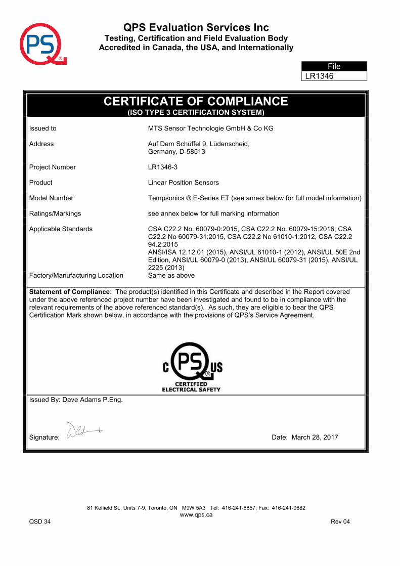
QPS Evaluation Services Inc Testing, Certification and Field Evaluation Body
Accredited in Canada, the USA, and Internationally
File LR1346
81 Kelfield St., Units 7-9, Toronto, ON M9W 5A3 Tel: 416-241-8857; Fax: 416-241-0682 www.qps.ca
QSD 34 Rev 04
CERTIFICATE OF COMPLIANCE (ISO TYPE 3 CERTIFICATION SYSTEM)
Issued to
MTS Sensor Technologie GmbH & Co KG
Address Auf Dem Schüffel 9, Lüdenscheid, Germany, D-58513
Project Number
LR1346-3
Product
Linear Position Sensors
Model Number
Tempsonics ® E-Series ET (see annex below for full model information)
Ratings/Markings see annex below for full marking information Applicable Standards
CSA C22.2 No. 60079-0:2015, CSA C22.2 No. 60079-15:2016, CSA C22.2 No 60079-31:2015, CSA C22.2 No 61010-1:2012, CSA C22.2 94.2:2015 ANSI/ISA 12.12.01 (2015), ANSI/UL 61010-1 (2012), ANSI/UL 50E 2nd Edition, ANSI/UL 60079-0 (2013), ANSI/UL 60079-31 (2015), ANSI/UL 2225 (2013)
Factory/Manufacturing Location
Same as above
Statement of Compliance: The product(s) identified in this Certificate and described in the Report covered under the above referenced project number have been investigated and found to be in compliance with the relevant requirements of the above referenced standard(s). As such, they are eligible to bear the QPS Certification Mark shown below, in accordance with the provisions of QPS’s Service Agreement.
Issued By: Dave Adams P.Eng.
Signature: Date: March 28, 2017
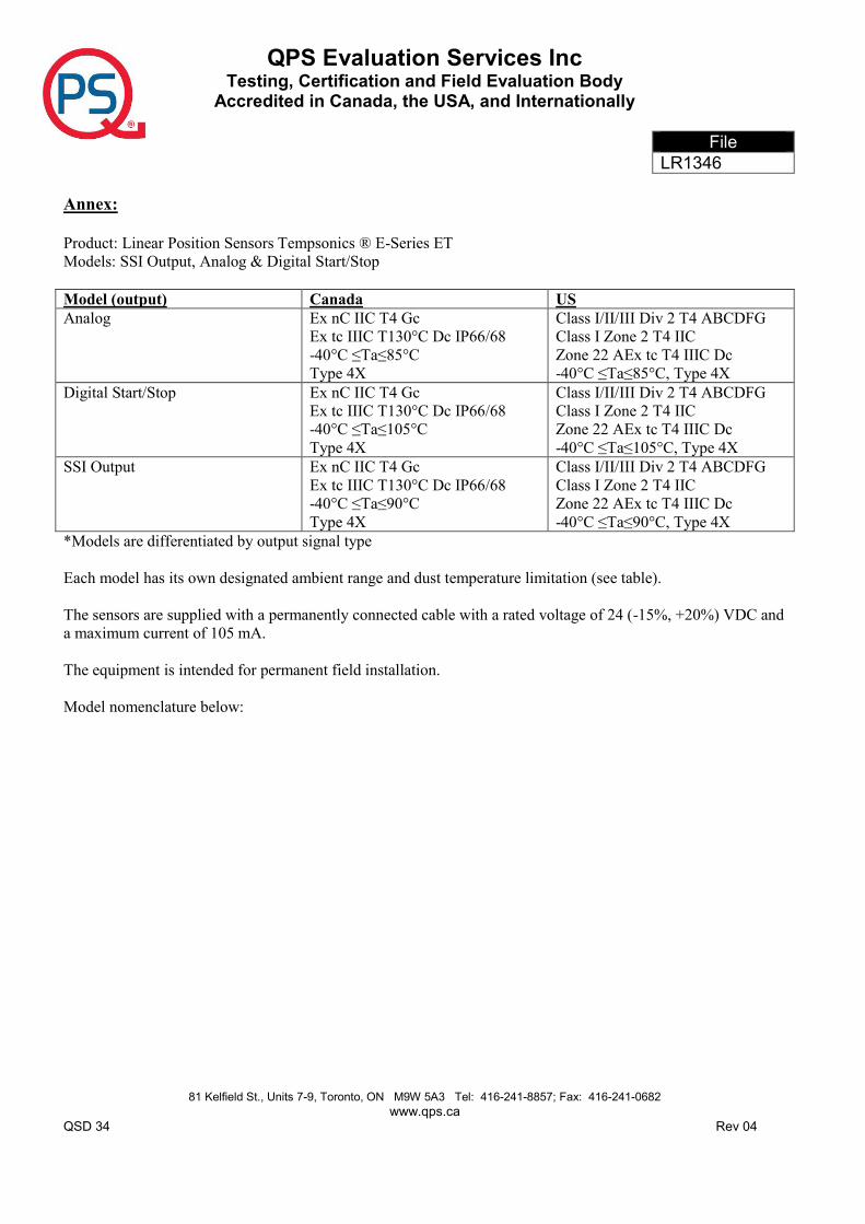
QPS Evaluation Services Inc Testing, Certification and Field Evaluation Body
Accredited in Canada, the USA, and Internationally
File LR1346
81 Kelfield St., Units 7-9, Toronto, ON M9W 5A3 Tel: 416-241-8857; Fax: 416-241-0682 www.qps.ca
QSD 34 Rev 04
Annex: Product: Linear Position Sensors Tempsonics ® E-Series ET Models: SSI Output, Analog & Digital Start/Stop Model (output) Canada US Analog Ex nC IIC T4 Gc
Ex tc IIIC T130°C Dc IP66/68 -40°C ≤Ta≤85°C Type 4X
Class I/II/III Div 2 T4 ABCDFG Class I Zone 2 T4 IIC Zone 22 AEx tc T4 IIIC Dc -40°C ≤Ta≤85°C, Type 4X
Digital Start/Stop Ex nC IIC T4 Gc Ex tc IIIC T130°C Dc IP66/68 -40°C ≤Ta≤105°C Type 4X
Class I/II/III Div 2 T4 ABCDFG Class I Zone 2 T4 IIC Zone 22 AEx tc T4 IIIC Dc -40°C ≤Ta≤105°C, Type 4X
SSI Output Ex nC IIC T4 Gc Ex tc IIIC T130°C Dc IP66/68 -40°C ≤Ta≤90°C Type 4X
Class I/II/III Div 2 T4 ABCDFG Class I Zone 2 T4 IIC Zone 22 AEx tc T4 IIIC Dc -40°C ≤Ta≤90°C, Type 4X
*Models are differentiated by output signal type Each model has its own designated ambient range and dust temperature limitation (see table). The sensors are supplied with a permanently connected cable with a rated voltage of 24 (-15%, +20%) VDC and a maximum current of 105 mA. The equipment is intended for permanent field installation. Model nomenclature below:
UNITED STATESMTS Systems Corporation
Sensors Division
3001 Sheldon DriveCary, N.C. 27513Phone: +1 919 677-0100E-mail: [email protected]
GERMANYMTS Sensor Technologie
GmbH & Co. KG
Auf dem Schüffel 958513 LüdenscheidPhone: +49 2351 9587-0E-mail: [email protected]
ITALYBranch Offi ce
Phone: +39 030 988 3819E-mail: [email protected]
FRANCEBranch Offi ce
Phone: +33 1 58 4390-28E-mail: [email protected]
GREAT BRITAIN Branch Offi ce
Phone: +44 79 44 15 03 00E-mail: [email protected]
CHINABranch Offi ce
Phone: +86 21 6485 5800 E-mail: [email protected]
JAPANBranch Offi ce
Phone: +81 42 707 7710E-mail: [email protected]
www.mtssensors.comMTS, Temposonics and Level Plus are registered trademarks of MTS Systems Corporation in the United States; MTS SENSORS and the MTS SENSORS logo are trademarks of MTS Systems Corporation within the United States. These trademarks may be protected in other countries. All other trademarks are the property of their respective owners. Copyright © 2018 MTS Systems Corporation. No license of any intellectual property rights is granted. MTS reserves the right to change the information within this document, change product designs, or withdraw products from availability for purchase without notice. Typographic and graphics errors or omissions are unintentional and subject to correction. Visit www.mtssensors.com for the latest product information.
Reg.-No. 003095-QM08
Document Part Number: 551890 Revision B (EN) 02/2018


