

Toshiba Global Commerce Solutions
Service Manual
4818-T10

2
Copyrights © 2018 All rights reserved. The information in this document is subject to change without prior notice in order to improve reliability, design and function and does not represent a commitment on the part of the manufacturer.
This document contains proprietary information protected by copyright. All rights are reserved. No part of this manual may be reproduced by any mechanical, electronic, or other means in any form without prior written permission of the manufacturer.
All trademarks are property of their respective owners
Liability Disclaimer In no event will the manufacturer be liable for direct, indirect, special, incidental, or consequential damages arising out of the use or inability to use the product or documentation, even if advised of the possibility of such damages. The information in this document is subject to change without notice

3
Contents
Copyrights .............................................................................................. 2
Liability Disclaimer ................................................................................ 2
Contents ................................................................................................. 3
Safety ...................................................................................................... 4
1. 4818-T10 Product Overview ............................................................ 5
2. Before You Start ............................................................................... 6
3. 4818-T10 Field Replaceable Unit .................................................... 7
4. Replacing Display Module .............................................................. 8
5. Replacing System Board ................................................................10
6. Replacing Stand Base Unit ............................................................13
7. Replacing Memory Module ............................................................14
8. Replacing M.2 Storage ...................................................................15
9. Replacing the coin battery .............................................................16
10. Replacing Speaker ..........................................................................17
11. Replacing 10” 2nd Display .............................................................18
12. Replacing 2X20 VFD .......................................................................19
13. Replacing MSR /MSR+iButton .......................................................20
14. System Board Connector /Function /Location .............................21
4
Safety
Before installing this product, read Safety Information from accessory bag.
Antes de instalar este produto, leia as Informações de Segurança.
Pred instalací tohoto produktu si prectete prírucku bezpecnostních instrukcí.
Læ s sikkerhedsforskrifterne, fø r du installerer dette produkt.
Lees voordat u dit product installeert eerst de veiligheidsvoorschriften.
Ennen kuin asennat tämän tuotteen, lue turvaohjeet kohdasta Safety
Information. Avant d'installer ce produit, lisez les consignes de sécurité.
Vor der Installation dieses Produkts die Sicherheitshinweise lesen.
Prima di installare questo prodotto, leggere le Informazioni sulla Sicurezza.
Les sikkerhetsinformasjonen (Safety Information) fø r du installerer dette produktet.
Antes de instalar este produto, leia as Informações sobre Segurança.
Antes de instalar este producto, lea la información de seguridad.
Läs säkerhetsinformationen innan du installerar den här produkten.
5
1. 1. 4818-T10 Product Overview 81
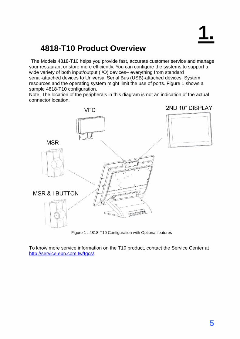
The Models 4818-T10 helps you provide fast, accurate customer service and manage your restaurant or store more efficiently. You can configure the systems to support a wide variety of both input/output (I/O) devices– everything from standard serial-attached devices to Universal Serial Bus (USB)-attached devices. System resources and the operating system might limit the use of ports. Figure 1 shows a sample 4818-T10 configuration. Note: The location of the peripherals in this diagram is not an indication of the actual connector location.
Figure 1 : 4818-T10 Configuration with Optional features
To know more service information on the T10 product, contact the Service Center at http://service.ebn.com.tw/tgcs/.

6
2. 2. Before You Start
1. Save and close all open files and exit all open applications. 2. Shut down your system. Push the Power button -> system Shut down.
NOTE: If you are using a different operating system, see the documentation of your operating system for shut-down instructions.
3. Please unplug the power cable before you start to work. 4. Please read and follow the instructions in this document carefully. Failure to
follow these instructions could damage your device and void the warranty.
Tools Suggested All procedures in this document require the following tools:
#1, #2 Phillips screwdriver
(Magnetized suggested)
1.5 mm hexagon socket spanner (Magnetized suggested)

7
3. 3. 4818-T10 Field Replaceable Unit
1. User can purchase FRU from Toshiba Service Center located at EMEA, Asia and US if you desire to conduct the maintenance and Hardware Service with your own resource.
Toshiba FRU PN Toshiba SMU PN Description
3AC00686700 3AA01400300 FRU, Display Module for 4818-T10
3AC00686800 3AA01400400 FRU, System Board for 4818-T10
3AC00686900 3AA01397300 FRU, Stand Base Assembly
3AC00687000 3AA01397400 FRU, 2nd Display Dummy Cover
3AC00687100 3AA01397500 FRU, MSR Dummy Cover
3AC00687200 3AA01397600 FRU, Cable Cover
3AC00687300 3AA01397700 FRU, Stand Cover
3AC00687400 3AA01397800 FRU, 128GB SATA SSD for 4818-T10
3AC00689100 3AA01397900 FRU, 4GB Memory for 4818-T10
3AC00689200 3AA01398000 FRU, Power Adopter
3AC00689300 3AA01398100 FRU, Speaker
3AC00689400 3AA01398200 FRU, RJ50 to RS232 Cable
3AC00689500 3AA01398300 FRU, Coin Cell Battery
3AC00689600 3AA01398400 FRU, Misc Hardware Kit
3AC00690100 3AA01398800 FRU, Falcon 2x20 Display
3AC00690200 3AA01399000 FRU, Falcon MSR
3AC00690300 3AA01399200 FRU, Falcon 2nd Display
3AC00690400 3AA01401000 FRU, Falcon MSR + iButton
3AC00724700 3AA01429800 FRU, System BOX Cover
2. User can maintain and replace the FRU according to below drawing (figure 2)
Figure 2

8
4. 4. Replacing Display Module
1. Remove the cable cover, stand cover and slightly uplift first.
2. Remove all IO cables. (LAN, 24V /12V PUSB, RS232, CD,mDP & USB)
3. Release 2 thumb screws of System board Box then slightly slide down
9
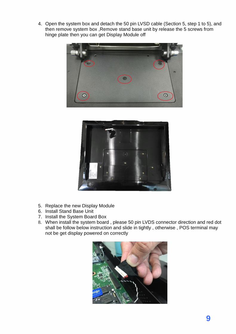
4. Open the system box and detach the 50 pin LVSD cable (Section 5, step 1 to 5), and then remove system box ,Remove stand base unit by release the 5 screws from hinge plate then you can get Display Module off
5. Replace the new Display Module 6. Install Stand Base Unit 7. Install the System Board Box 8. When install the system board , please 50 pin LVDS connector direction and red dot
shall be follow below instruction and slide in tightly , otherwise , POS terminal may not be get display powered on correctly
10
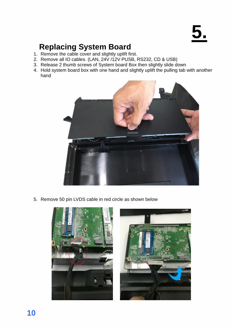
5. 5. Replacing System Board
1. Remove the cable cover and slightly uplift first. 2. Remove all IO cables. (LAN, 24V /12V PUSB, RS232, CD & USB) 3. Release 2 thumb screws of System board Box then slightly slide down 4. Hold system board box with one hand and slightly uplift the pulling tab with another
hand
5. Remove 50 pin LVDS cable in red circle as shown below
11
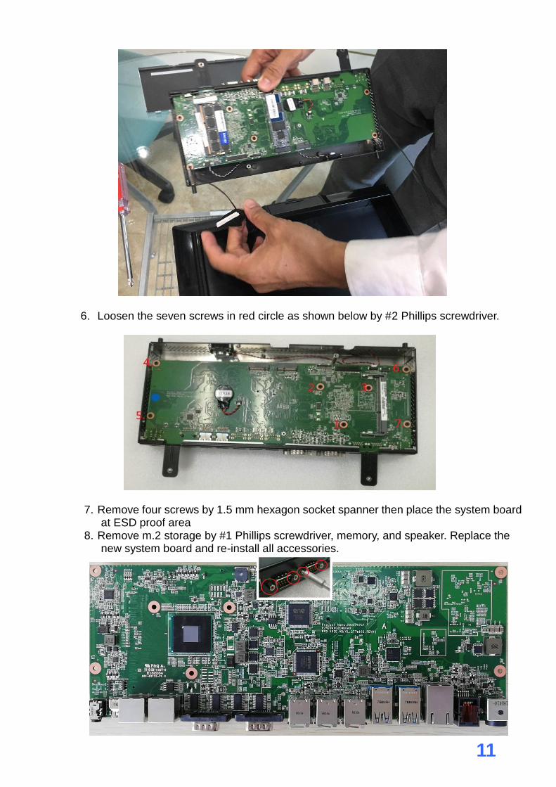
6. Loosen the seven screws in red circle as shown below by #2 Phillips screwdriver.
7. Remove four screws by 1.5 mm hexagon socket spanner then place the system board at ESD proof area
8. Remove m.2 storage by #1 Phillips screwdriver, memory, and speaker. Replace the new system board and re-install all accessories.

12
9. When install the system board, please notice the 50 pin LVDS connector and red dot
direction as below instruction and slide in the connector tightly, otherwise, the
connector and PCBA may be damaged.”
13
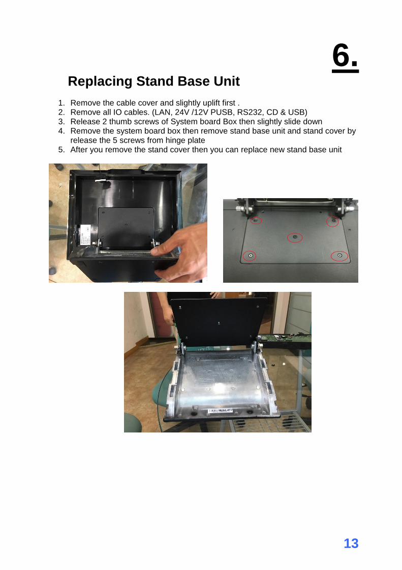
6. 6. Replacing Stand Base Unit
1. Remove the cable cover and slightly uplift first . 2. Remove all IO cables. (LAN, 24V /12V PUSB, RS232, CD & USB) 3. Release 2 thumb screws of System board Box then slightly slide down 4. Remove the system board box then remove stand base unit and stand cover by
release the 5 screws from hinge plate 5. After you remove the stand cover then you can replace new stand base unit
14
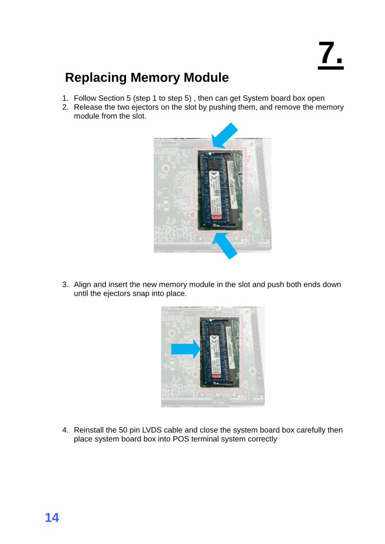
7. 7. Replacing Memory Module
1. Follow Section 5 (step 1 to step 5) , then can get System board box open 2. Release the two ejectors on the slot by pushing them, and remove the memory
module from the slot.
3. Align and insert the new memory module in the slot and push both ends down until the ejectors snap into place.
4. Reinstall the 50 pin LVDS cable and close the system board box carefully then place system board box into POS terminal system correctly

15
8. 8. Replacing M.2 Storage
1. Follow Section 5 (step 1 to step 5) , then can get System board box open 2. Loosen screw with #1 Philips screw driver , and remove the M.2 from the slot.
3. Align and insert the new M.2 storage in the slot and push end down into place and tighten the screw .
16
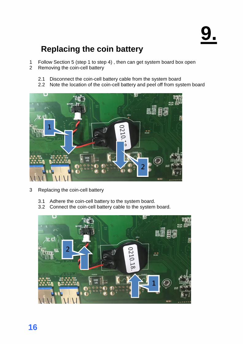
9. 9. Replacing the coin battery
1 Follow Section 5 (step 1 to step 4) , then can get system board box open 2 Removing the coin-cell battery
2.1 Disconnect the coin-cell battery cable from the system board 2.2 Note the location of the coin-cell battery and peel off from system board
3 Replacing the coin-cell battery 3.1 Adhere the coin-cell battery to the system board. 3.2 Connect the coin-cell battery cable to the system board.
1
2
1
2
17
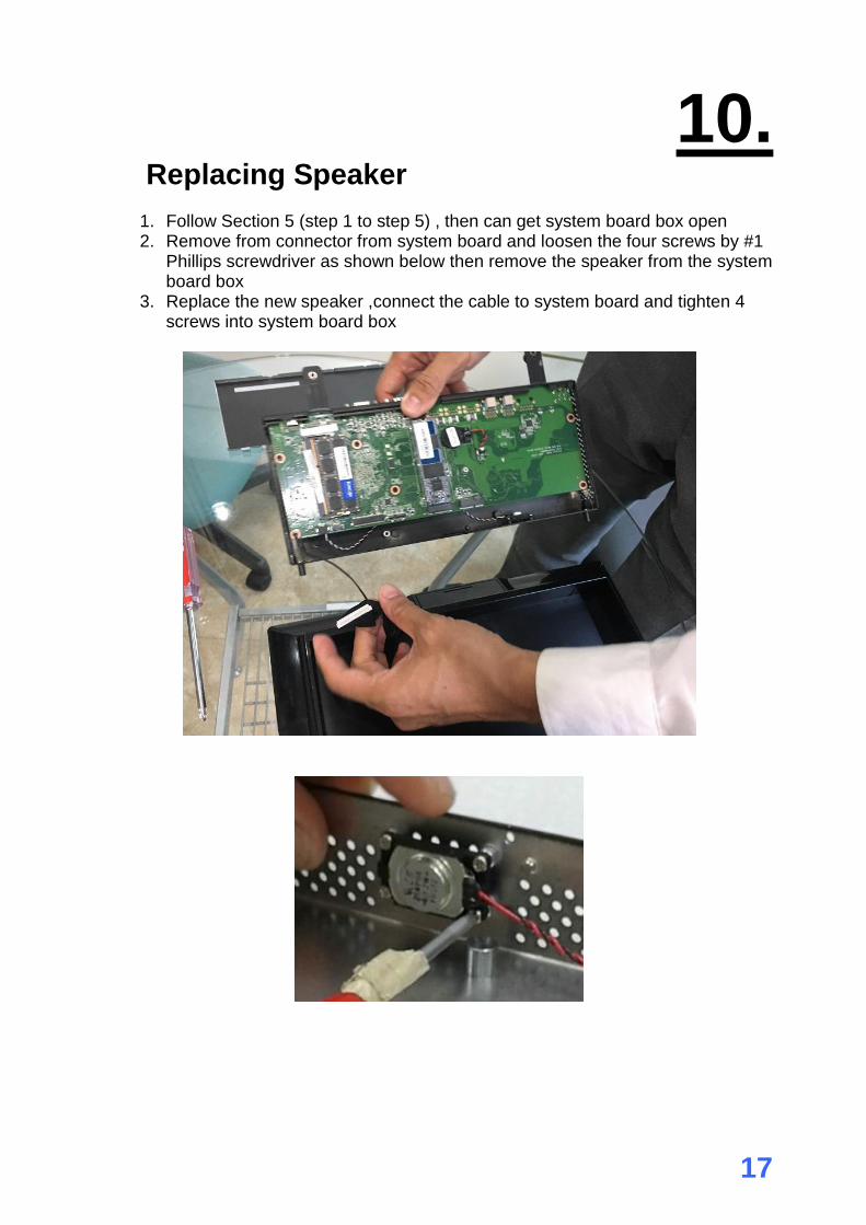
10. 10. Replacing Speaker
1. Follow Section 5 (step 1 to step 5) , then can get system board box open 2. Remove from connector from system board and loosen the four screws by #1
Phillips screwdriver as shown below then remove the speaker from the system board box
3. Replace the new speaker ,connect the cable to system board and tighten 4 screws into system board box
18
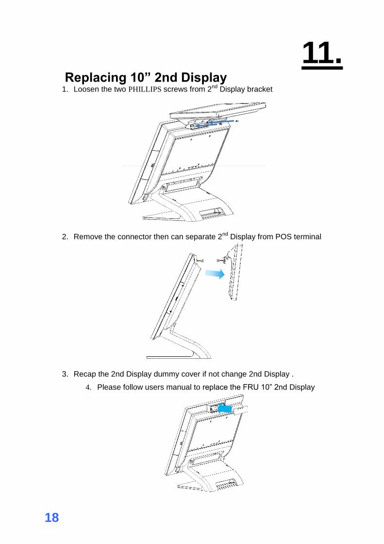
1111. 11. Replacing 10” 2nd Display
1. Loosen the two PHILLIPS screws from 2nd Display bracket
2. Remove the connector then can separate 2nd Display from POS terminal
3. Recap the 2nd Display dummy cover if not change 2nd Display .
4. Please follow users manual to replace the FRU 10” 2nd Display

19
1112. 12. Replacing 2X20 VFD
1. Loosen the two PHILLIPS screws from VFD bracket
2. Remove the connector then can separate VFD from POS terminal
3. Recap the 2nd display dummy cover if not change VFD.
4. Please follow users manual to replace the FRU VFD

20
1113. 13. Replacing MSR /MSR+iButton
1. Loosen the two PHILLIPS screws from MSR bracket
2. Remove the MSR from POS terminal and remove MSR bracket
3. Recap the MSR dummy cover if not change MSR
4. Please follow users manual to replace the FRU MSR
21
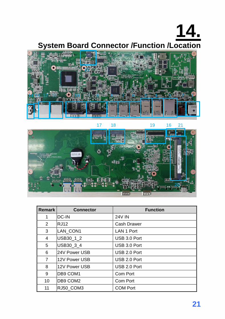
1114. 14. System Board Connector /Function /Location
16
Remark Connector Function
1 DC-IN 24V IN
2 RJ12 Cash Drawer
3 LAN_CON1 LAN 1 Port
4 USB30_1_2 USB 3.0 Port
5 USB30_3_4 USB 3.0 Port
6 24V Power USB USB 2.0 Port
7 12V Power USB USB 2.0 Port
8 12V Power USB USB 2.0 Port
9 DB9 COM1 Com Port
10 DB9 COM2 Com Port
11 RJ50_COM3 COM Port
1
2
3
4
5
6 7
8
9
10 11 12 14 13
17 18 19 16 21
20
15
22
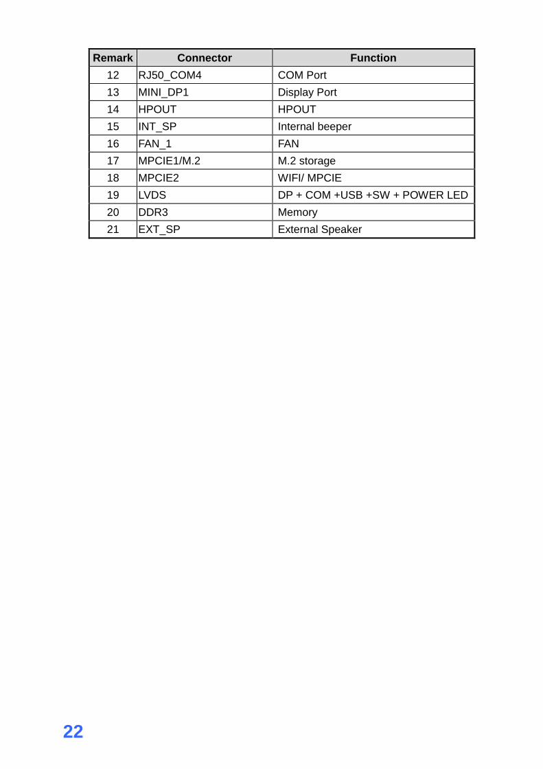
Remark Connector Function
12 RJ50_COM4 COM Port
13 MINI_DP1 Display Port
14 HPOUT HPOUT
15 INT_SP Internal beeper
16 FAN_1 FAN
17 MPCIE1/M.2 M.2 storage
18 MPCIE2 WIFI/ MPCIE
19 LVDS DP + COM +USB +SW + POWER LED
20 DDR3 Memory
21 EXT_SP External Speaker


