
IOSR Journal of Electrical and Electronics Engineering (IOSR-JEEE)
e-ISSN: 2278-1676,p-ISSN: 2320-3331, Volume 12, Issue 1 Ver. II (Jan. – Feb. 2017), PP 30-44
www.iosrjournals.org
DOI: 10.9790/1676-1201023044 www.iosrjournals.org 30 | Page
Tuning of PI and PID Controller with STATCOM, SSSC and
UPFC for Minimizing Damping of Oscillation
Sobuj Kumar Ray1, Md. Arifur Rahman
2 and Md. Raju Ahmed
3
1(M. Engineering Student, Department EEE, Dhaka University of Engineering and Technology, Bangladesh)
2(Assistant Professor, Department EEE, Dhaka University of Engineering and Technology, Bangladesh)
3(Professor, Department EEE, Dhaka University of Engineering and Technology, Bangladesh)
Email:[email protected], [email protected]
3
Abstract: This paper presents the comparative performance of directly and feedback connected PI and PID
controller scheme with Flexible AC Transmission System (FACTS) devices, such as Static Synchronous
Compensator (STATCOM), Static Synchronous Series Compensator (SSSC) and Unified Power Flow Controller
(UPFC) in terms of improvements in transient stability, extenuation of system oscillations and furnishing
voltage support in single machine infinite bus system (SMIB). Firstly, rotor angle deviation and speed deviation
analyzed for directly connected PI and PID with UPFC, SSSC and STATCOM then for feedback connected. The
comparisons of all the results are performed using Matlab simulink in term of maximum overshoot and settling
time.
Keywords: PID, PI, STATCOM, SSSC and UPFC.
I. Introduction The National grid of Bangladesh failed after the transmission line experienced a "technical glitch" that
led to a cascade of failures throughout the national power grid, with power plants and substations shutting down
on 1st November 2014. In the year 2003, North America and Europe have experienced a number of series
blackouts [1, 2]. These blackouts call for a novel algorithm of controlling mechanism and minimizing the effect
of failure for a safe and more reliable power system operation. Such types of blackouts usually occur due to the
disturbance of rotor angle and corresponding instability of the turbines of generators. In order to reduce the
effect of aperiodic small disturbance (ASD) [3] and large disturbance of rotor angle instability [4], a number of
approaches have been already deployed in many times.
The closed loop control system stables the single machine operating condition due to impact of loss of
generating unit and large sudden change in load. For the FACTS damping controllers of the feedback signals are
realized by evaluating the modal residues of each feedback signal to the system input [5]. To stabilize the power
system by damping interarea power oscillations and by improving the transient stability of the system a thyristor
switched series capacitor (TSSC) has been incorporated [6]. Flexible ac transmission system (FACTS) devices
are being applied to improve power transfer capability of ac transmission networks and to enhance the
controllability of power flow and voltage thus augmenting power system stability due to continuing
developments in power electronic technologies. Among the FACTS devices, the Static Synchronous
Compensator (STATCOM) is able to improve the transfer capability of a power system by enhancing voltage
regulation and stability. These can significantly provide smooth and for improving both damping of power
oscillations [7, 9] and transient stability and rapid reactive power compensation for voltage support [10]. In
addition the STATCOM carries a reactive current to regulate the voltage independently [11, 12, 13, 14] and
control grid fault [15, 16]. The Static Synchronous Series Compensator (SSSC) comprises of a voltage source
converter in series with coupling transformer in the line. SSSC can inject a voltage with controllable magnitude
and phase angle at the line frequency and found to be more capable of handling power flow control,
improvements of transient stability and damping of oscillations [17, 18, 19].
There are two solid state voltage source converters (VSCs) in the unified power flow controller
(UPFC). The VSCs are colligated via a common DC link capacitor. One of the VSCs is STATCOM which is
shunt connected and the other is SSSC which is series connected. Both VSCs injects a nearly sinusoidal current
of variable magnitude. STATCOM injects current in quadrature with the line voltage and at the point of
association whereas SSSC injects current in quadrature with the line current. STATCOM and SSSC exchange
solely reactive power at their terminal when they operate as standalone controllers with open dc link switch. At
the point when both of the VSCs works together with the dc link switch, the injected voltage which lies in series
with the line can take any angle with respect to the line current. As a result, the power that is exchanged at the
terminals of SSSC can take any form either real or reactive. The real power can be exchanged by the SSSC with
the line flows bi-directionally to the line through the STATCOM and the common dc link capacitor. The UPFC
has been used widely to improve damping and dynamic performance of the system [20, 21] and also enhancing
reliability of power system [22]. To incorporate synchronous AC grid, UPFC is also used in the system [23]
Tuning of PI and PID Controller with STATCOM, SSSC and UPFC for Minimizing Damping of
DOI: 10.9790/1676-1201023044 www.iosrjournals.org 31 | Page
First rotor angle deviation and speed deviation are analyzed with and without FACT devices in a Single-
Machine Infinite Bus (SMIB) power system, and then PID controller is incorporated with feedback signal [24]
but it is usually introduced before the plant. This paper proposes the PID and PI controllers in coordination
with damping schemes like STATCOM, SSSC and UPFC to improve the damping of oscillations in power
system. Different of electrical and mechanical signals are applied to PID controller then output of PID controller
is incorporated to STATCOM, SSSC and UPFC. The designed controllers are tested in single machine
environment.
II. Optimizations of PI And PID Controllers 1.1 PI Controller
PI controller has been used in recent years with the purpose of improving the transient and the steady-
state performance and also for rejection of disturbances caused by operation events throughout startup [25, 26,
27]. It comprises of proportional action and integral action. The proportional controller dimineshes the system
error by using proportion of system error to control the system. However, this incorporate an offset error into the
system. The integral controller output is proportional to the amount of time there is an error present in the
system. The integral action eliminates the offset which is introduced by the proportional control but incorporates
a phase lag into the system. The PI controller tuning parameters PK and IK have been optimized by PID
tuning with actuator constraint.
Table 1 PI Controller Gain Parameter Parameters
PK IK
Gain with actuator constraints for linear block 3.715 -0.4762
Gain for simulation 3.715 -0.4762
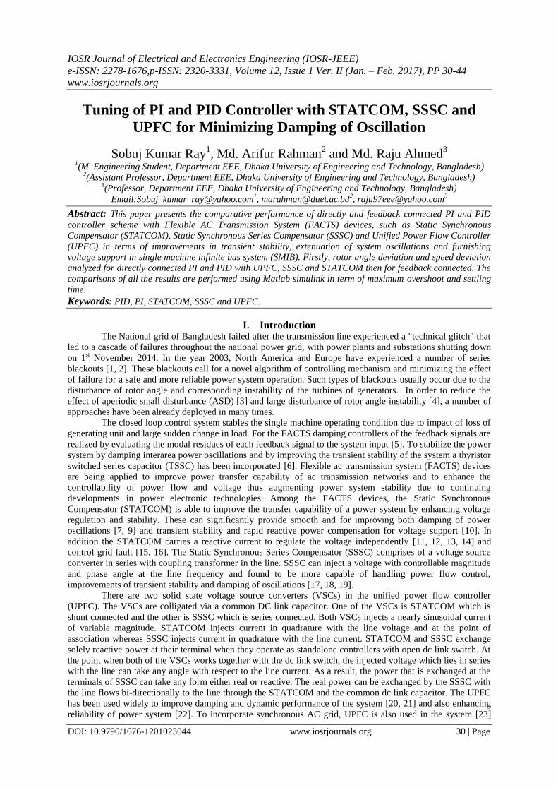
1.2 PID Controller
The PID controller is a “three modes” controller. The value of three tuning parameters the proportional,
integral and derivative determine the performance and activity of these controllers. The three control actions that
are P control action, I control action and D control action work together to get the continuous PID controller.
PID controller has been developed in order to improve transient performance and speed control of motor [28,
29] generator A discrete PID controller is incorporated into the system for diminishing nonlinear damping [30].
The tuning value of gain (KP, KI, KD) may be obtained from Steepest Gradient Descent Method (SDGM) [31]
and as well as Genetic Algorithms Method [32] and also Ziegler–Nichols tuning method. In the proposed
controller, the gain parameter ( PK , IK and DK ) of PID controller has been tuned by PID tuning with actuator
constraint. This gain parameters have been manupulated due to non-linear block present in the system which
have been shown in Table 2.
Step Scope
1.646
Proportional Gain
Kp
u y
Plant
e u
PID Controller
Output Constraint
0.7671
Integral Gain
Ki
0.4633
Derivative Gain
Kd
Actuator Constraint
Figure 1 PID Tuning with Actuator Constraints Using Matlab.
Table 2 PID Controller Gain Parameter Parameters
PK IK DK
Gain with actuator constraints for linear block 1.646 0.7671 0.4633
Gain for Proposed Methodology 15 0.01083 0.4673
Tuning of PI and PID Controller with STATCOM, SSSC and UPFC for Minimizing Damping of
DOI: 10.9790/1676-1201023044 www.iosrjournals.org 32 | Page
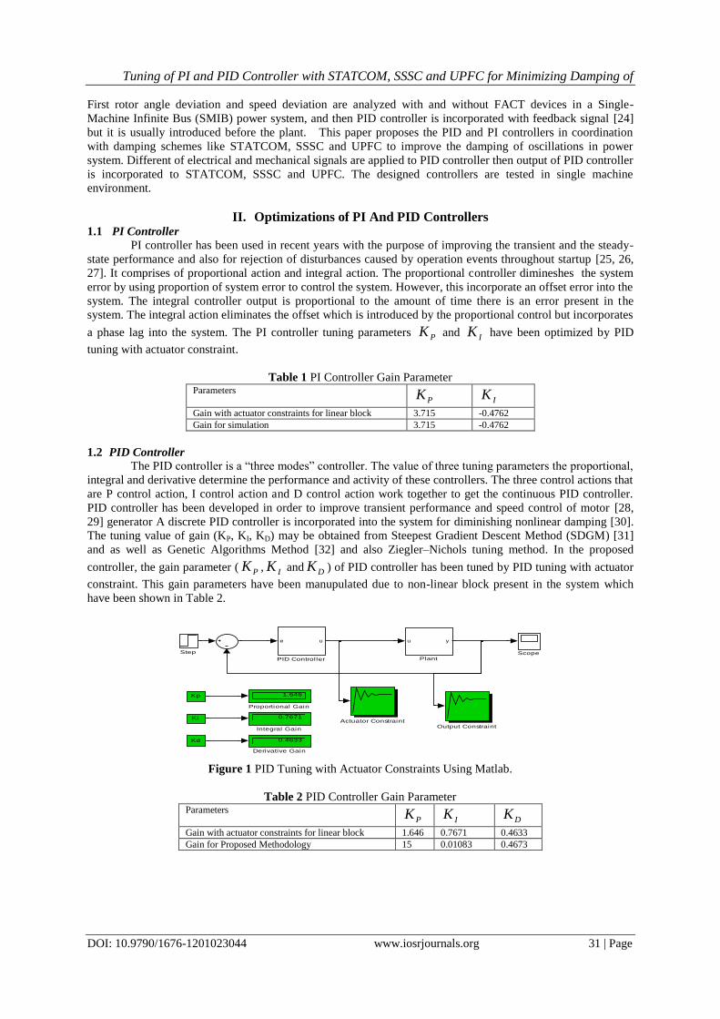
III. Mathematical Representation of Single Machine Infinite Bus A generator connected to a substation whose bus voltage and frequency are constant through a very
long transmission line. The characteristic of bus voltage remains constant through the power supplied or
consumed by any device connected to it.
Figure 2 Single Machine Infinite Bus systems [24]
The equivalent circuit of the system is shown in Figure 3, where 1X represent the equivalent reactance between
machine internal bus and the impedance 2X represent the equivalent reactance between the bus m and the
infinite bus.
Figure 3 Equivalent circuit of Single Machine Infinite Bus system [24]
The magnitude of the machine internal voltage and the infinite bus voltage is represented by E‟ and V,
respectively. The equation describing the relative motion between rotor axis and the magnetic field axis is
known as the swing equation. Under normal condition, the rotor remains to its original position but if the
disturbance is created due to any fault or sudden load, the rotor comes to a new operating power angle relative to
the synchronous revolving field.
The swing equation can be express in term of inertia constant
dt
d (1)
)(1
2
2
DPP
Mdt
d
dt
dem (2)
Here δ= the rotor angle deviation,
= the rotor angle deviation,
M= moment of inertia,
Pm = input mechanical power, and
D= damping coefficient.
The simplified form of power flow equation in Figure 3 can be written as
SinPPe max (3)
Where
21
'
maxXX
VEP
(4)
Tuning of PI and PID Controller with STATCOM, SSSC and UPFC for Minimizing Damping of
DOI: 10.9790/1676-1201023044 www.iosrjournals.org 33 | Page
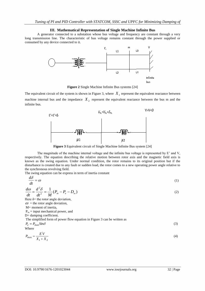
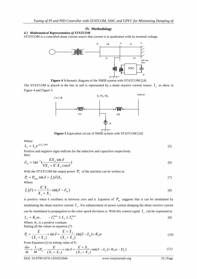
IV. Methodology 4.1 Mathematical Representation of STATCOM
STATCOM is a controlled shunt current source that current is in quadrature with its terminal voltage.
Figure 4 Schematic diagram of the SMIB system with STATCOM [24]
The STATCOM is placed in the bus m and is represented by a shunt reactive current source sI as show in
Figure 4 and Figure 5.
Figure 5 Equivalent circuit of SMIB system with STATCOM [24]
Where )90(
mj
SS eII
(5)
Positive and negative signs indicate for the inductive and capacitive respectively.
Here
)cos
sin(tan
2
'
1
21
XEVX
EXm
(6)
With the STATCOM the output power eP of the machine can be written as
Se IfPP )(sin 1max (7)
Where
)sin()(21
2
'
1 mXX
XEf
(8)
is positive when δ oscillates in between zero and π. Equation of mP suggests that it can be modulated by
modulating the shunt reactive current sI . For enhancement of power system damping the shunt reactive current
can be modulated in propagation to the rotor speed deviation ω. With this control signal sI can be expressed as
1KI S , maxmax
SSS III (9)
Where, K1 is a positive constant.
Putting all the values in equation (7)
1
21
2
'
21
'
)sin()(
sin)(
KXX
XE
XX
EP me
(10)
From Equation (2) in setting value of Pe
})sin()(
sin)(
{1
1
21
2
'
21
'
DKXX
XE
XX
EP
Mdt
dmm
(11)
Tuning of PI and PID Controller with STATCOM, SSSC and UPFC for Minimizing Damping of
DOI: 10.9790/1676-1201023044 www.iosrjournals.org 34 | Page
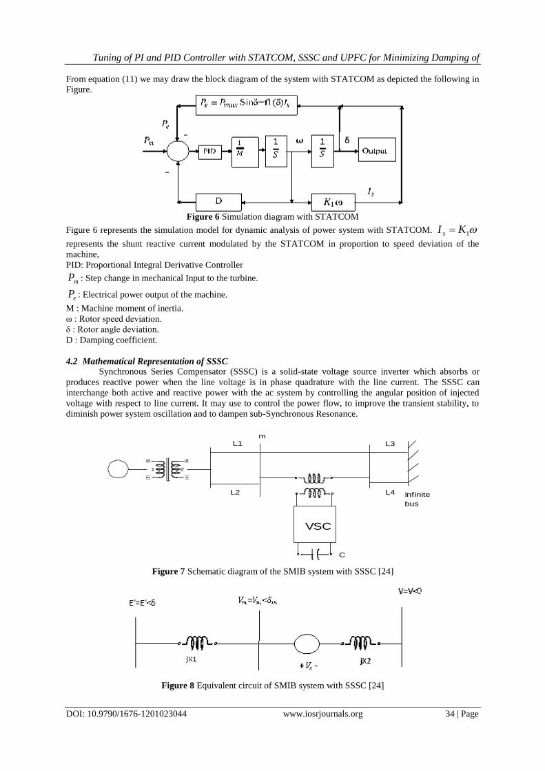
From equation (11) we may draw the block diagram of the system with STATCOM as depicted the following in
Figure.
Figure 6 Simulation diagram with STATCOM
Figure 6 represents the simulation model for dynamic analysis of power system with STATCOM. 1KI s
represents the shunt reactive current modulated by the STATCOM in proportion to speed deviation of the
machine,
PID: Proportional Integral Derivative Controller
mP : Step change in mechanical Input to the turbine.
eP : Electrical power output of the machine.
M : Machine moment of inertia.
ω : Rotor speed deviation.
δ : Rotor angle deviation.
D : Damping coefficient.
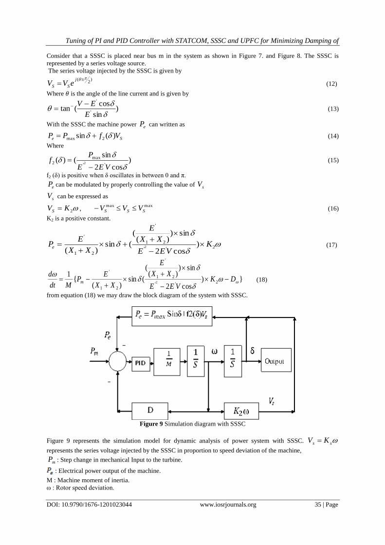
4.2 Mathematical Representation of SSSC
Synchronous Series Compensator (SSSC) is a solid-state voltage source inverter which absorbs or
produces reactive power when the line voltage is in phase quadrature with the line current. The SSSC can
interchange both active and reactive power with the ac system by controlling the angular position of injected
voltage with respect to line current. It may use to control the power flow, to improve the transient stability, to
diminish power system oscillation and to dampen sub-Synchronous Resonance.
1 2
m
Infinite
bus
L1 L3
L4L2
C
VSC
Figure 7 Schematic diagram of the SMIB system with SSSC [24]
Figure 8 Equivalent circuit of SMIB system with SSSC [24]
Tuning of PI and PID Controller with STATCOM, SSSC and UPFC for Minimizing Damping of
DOI: 10.9790/1676-1201023044 www.iosrjournals.org 35 | Page
Consider that a SSSC is placed near bus m in the system as shown in Figure 7. and Figure 8. The SSSC is
represented by a series voltage source.
The series voltage injected by the SSSC is given by
)2
(
j
SS eVV (12)
Where 𝜃 is the angle of the line current and is given by
)sin
cos(tan
'
'
E
EV
(13)
With the SSSC the machine power eP can written as
Se VfPP )(sin 2max (14)
Where
)cos2
sin()(
''
max
2 2
VEE
Pf
(15)
f2 (δ) is positive when δ oscillates in between 0 and π.
eP can be modulated by properly controlling the value of sV
sV can be expressed as
2KVS , maxmax
SSS VVV (16)
K2 is a positive constant.
2''
21
'
21
'
)cos2
sin))(
(
(sin)(
2 KVEE
XX
E
XX
EPe
(17)
})cos2
sin))(
(
(sin)(
{1
2''
21
'
21
'
2
DKVEE
XX
E
XX
EP
Mdt
dm
(18)
from equation (18) we may draw the block diagram of the system with SSSC.
Figure 9 Simulation diagram with SSSC
Figure 9 represents the simulation model for dynamic analysis of power system with SSSC. ss KV
represents the series voltage injected by the SSSC in proportion to speed deviation of the machine,
mP : Step change in mechanical Input to the turbine.
: Electrical power output of the machine.
M : Machine moment of inertia.
ω : Rotor speed deviation.
Tuning of PI and PID Controller with STATCOM, SSSC and UPFC for Minimizing Damping of
DOI: 10.9790/1676-1201023044 www.iosrjournals.org 36 | Page
δ : Rotor angle deviation.
D : Damping coefficient.
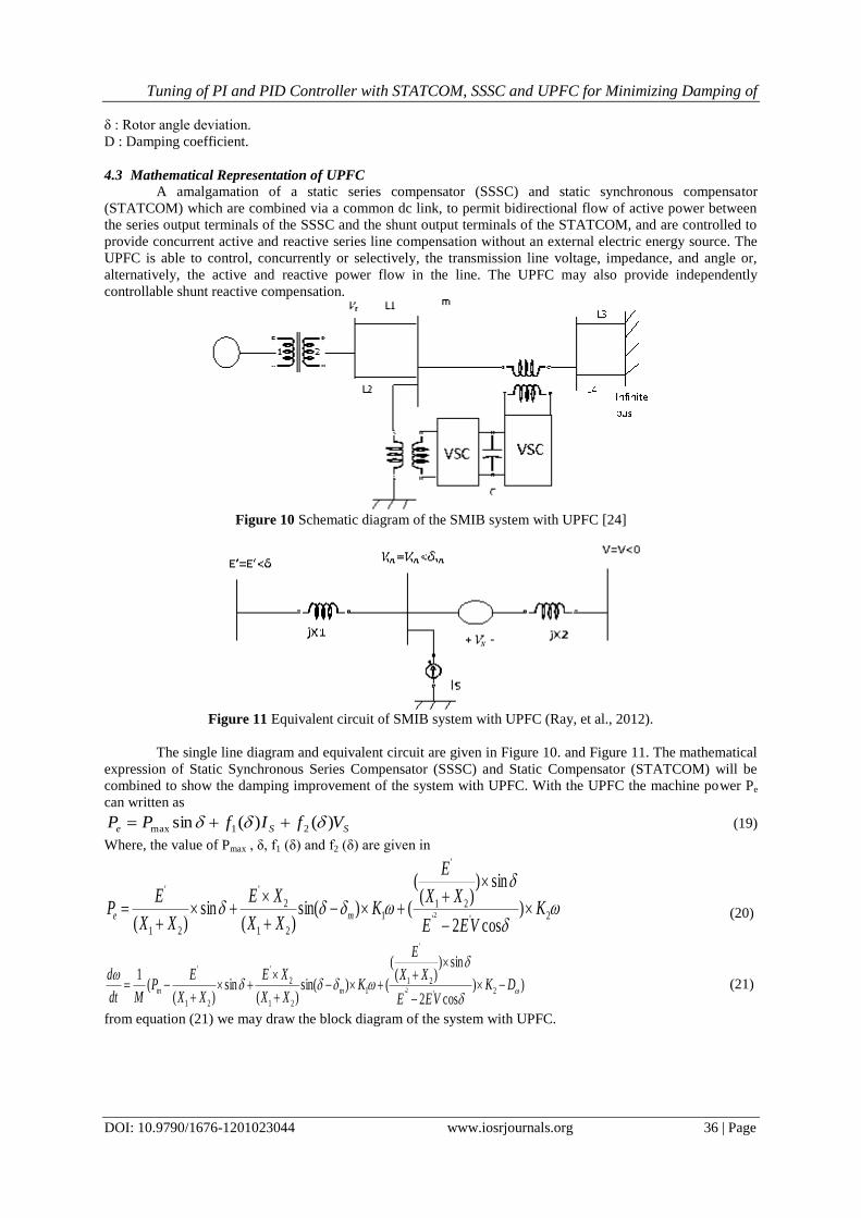
4.3 Mathematical Representation of UPFC
A amalgamation of a static series compensator (SSSC) and static synchronous compensator
(STATCOM) which are combined via a common dc link, to permit bidirectional flow of active power between
the series output terminals of the SSSC and the shunt output terminals of the STATCOM, and are controlled to
provide concurrent active and reactive series line compensation without an external electric energy source. The
UPFC is able to control, concurrently or selectively, the transmission line voltage, impedance, and angle or,
alternatively, the active and reactive power flow in the line. The UPFC may also provide independently
controllable shunt reactive compensation.
Figure 10 Schematic diagram of the SMIB system with UPFC [24]
Figure 11 Equivalent circuit of SMIB system with UPFC (Ray, et al., 2012).
The single line diagram and equivalent circuit are given in Figure 10. and Figure 11. The mathematical
expression of Static Synchronous Series Compensator (SSSC) and Static Compensator (STATCOM) will be
combined to show the damping improvement of the system with UPFC. With the UPFC the machine power Pe
can written as
SSe VfIfPP )()(sin 21max (19)
Where, the value of Pmax , δ, f1 (δ) and f2 (δ) are given in
2''
21
'
1
21
2
'
21
'
)cos2
sin))(
(
()sin()(
sin)(
2 KVEE
XX
E
KXX
XE
XX
EP me
(20)
))cos2
sin))(
(
()sin()(
sin)(
(1
2''
21
'
1
21
2
'
21
'
2
DKVEE
XX
E
KXX
XE
XX
EP
Mdt
dmm
(21)
from equation (21) we may draw the block diagram of the system with UPFC.
Tuning of PI and PID Controller with STATCOM, SSSC and UPFC for Minimizing Damping of
DOI: 10.9790/1676-1201023044 www.iosrjournals.org 37 | Page
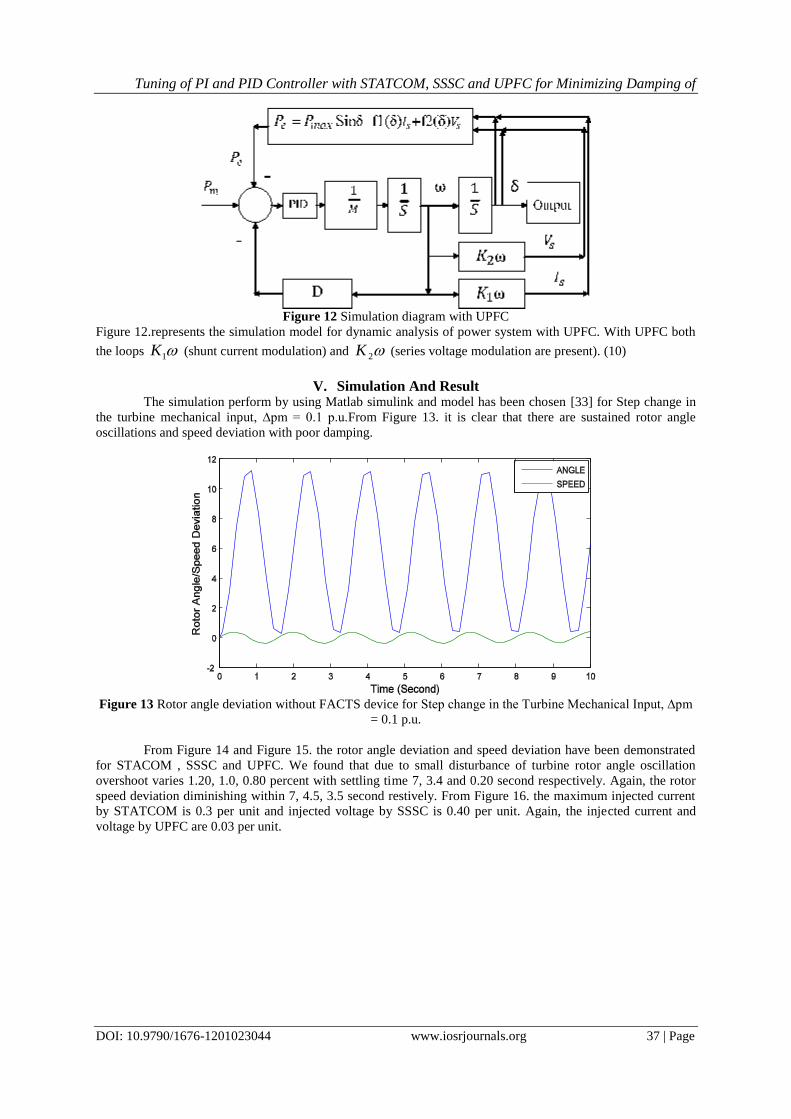
Figure 12 Simulation diagram with UPFC
Figure 12.represents the simulation model for dynamic analysis of power system with UPFC. With UPFC both
the loops 1K (shunt current modulation) and 2K (series voltage modulation are present). (10)
V. Simulation And Result The simulation perform by using Matlab simulink and model has been chosen [33] for Step change in
the turbine mechanical input, ∆pm = 0.1 p.u.From Figure 13. it is clear that there are sustained rotor angle
oscillations and speed deviation with poor damping.
Figure 13 Rotor angle deviation without FACTS device for Step change in the Turbine Mechanical Input, ∆pm
= 0.1 p.u.
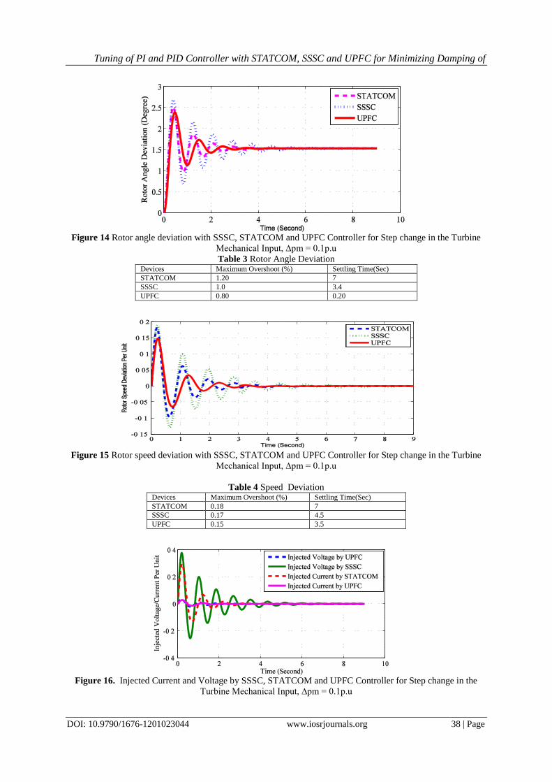
From Figure 14 and Figure 15. the rotor angle deviation and speed deviation have been demonstrated
for STACOM , SSSC and UPFC. We found that due to small disturbance of turbine rotor angle oscillation
overshoot varies 1.20, 1.0, 0.80 percent with settling time 7, 3.4 and 0.20 second respectively. Again, the rotor
speed deviation diminishing within 7, 4.5, 3.5 second restively. From Figure 16. the maximum injected current
by STATCOM is 0.3 per unit and injected voltage by SSSC is 0.40 per unit. Again, the injected current and
voltage by UPFC are 0.03 per unit.
Tuning of PI and PID Controller with STATCOM, SSSC and UPFC for Minimizing Damping of
DOI: 10.9790/1676-1201023044 www.iosrjournals.org 38 | Page
Figure 14 Rotor angle deviation with SSSC, STATCOM and UPFC Controller for Step change in the Turbine
Mechanical Input, ∆pm = 0.1p.u
Table 3 Rotor Angle Deviation Devices Maximum Overshoot (%) Settling Time(Sec)
STATCOM 1.20 7
SSSC 1.0 3.4
UPFC 0.80 0.20
Figure 15 Rotor speed deviation with SSSC, STATCOM and UPFC Controller for Step change in the Turbine
Mechanical Input, ∆pm = 0.1p.u
Table 4 Speed Deviation Devices Maximum Overshoot (%) Settling Time(Sec)
STATCOM 0.18 7
SSSC 0.17 4.5
UPFC 0.15 3.5
Figure 16. Injected Current and Voltage by SSSC, STATCOM and UPFC Controller for Step change in the
Turbine Mechanical Input, ∆pm = 0.1p.u
Tuning of PI and PID Controller with STATCOM, SSSC and UPFC for Minimizing Damping of
DOI: 10.9790/1676-1201023044 www.iosrjournals.org 39 | Page
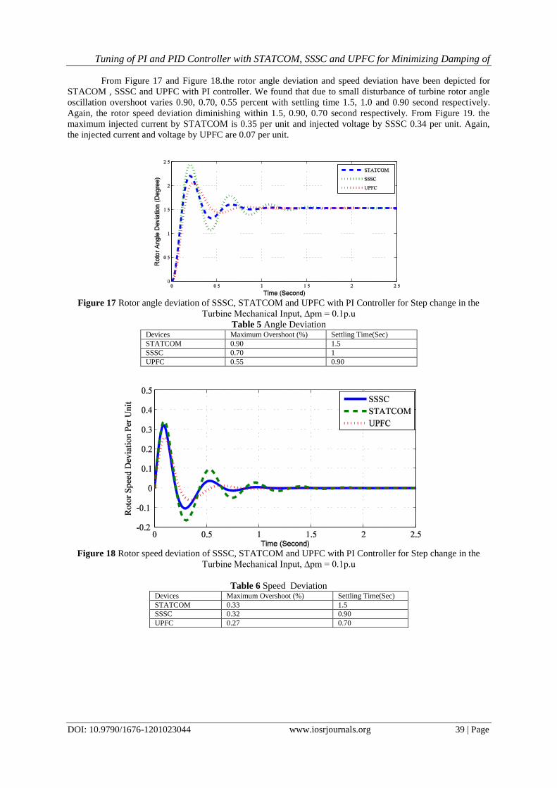
From Figure 17 and Figure 18.the rotor angle deviation and speed deviation have been depicted for
STACOM , SSSC and UPFC with PI controller. We found that due to small disturbance of turbine rotor angle
oscillation overshoot varies 0.90, 0.70, 0.55 percent with settling time 1.5, 1.0 and 0.90 second respectively.
Again, the rotor speed deviation diminishing within 1.5, 0.90, 0.70 second respectively. From Figure 19. the
maximum injected current by STATCOM is 0.35 per unit and injected voltage by SSSC 0.34 per unit. Again,
the injected current and voltage by UPFC are 0.07 per unit.
Figure 17 Rotor angle deviation of SSSC, STATCOM and UPFC with PI Controller for Step change in the
Turbine Mechanical Input, ∆pm = 0.1p.u
Table 5 Angle Deviation Devices Maximum Overshoot (%) Settling Time(Sec)
STATCOM 0.90 1.5
SSSC 0.70 1
UPFC 0.55 0.90
Figure 18 Rotor speed deviation of SSSC, STATCOM and UPFC with PI Controller for Step change in the
Turbine Mechanical Input, ∆pm = 0.1p.u
Table 6 Speed Deviation Devices Maximum Overshoot (%) Settling Time(Sec)
STATCOM 0.33 1.5
SSSC 0.32 0.90
UPFC 0.27 0.70
Tuning of PI and PID Controller with STATCOM, SSSC and UPFC for Minimizing Damping of
DOI: 10.9790/1676-1201023044 www.iosrjournals.org 40 | Page
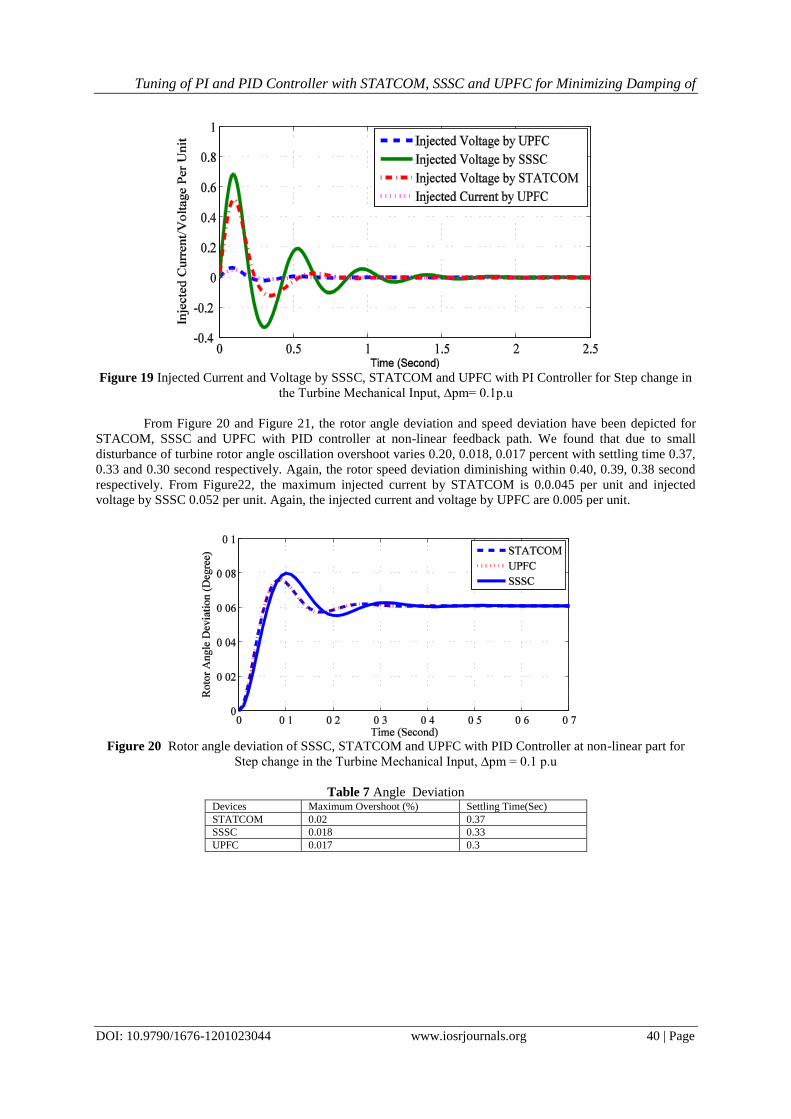
Figure 19 Injected Current and Voltage by SSSC, STATCOM and UPFC with PI Controller for Step change in
the Turbine Mechanical Input, ∆pm= 0.1p.u
From Figure 20 and Figure 21, the rotor angle deviation and speed deviation have been depicted for
STACOM, SSSC and UPFC with PID controller at non-linear feedback path. We found that due to small
disturbance of turbine rotor angle oscillation overshoot varies 0.20, 0.018, 0.017 percent with settling time 0.37,
0.33 and 0.30 second respectively. Again, the rotor speed deviation diminishing within 0.40, 0.39, 0.38 second
respectively. From Figure22, the maximum injected current by STATCOM is 0.0.045 per unit and injected
voltage by SSSC 0.052 per unit. Again, the injected current and voltage by UPFC are 0.005 per unit.
Figure 20 Rotor angle deviation of SSSC, STATCOM and UPFC with PID Controller at non-linear part for
Step change in the Turbine Mechanical Input, ∆pm = 0.1 p.u
Table 7 Angle Deviation Devices Maximum Overshoot (%) Settling Time(Sec)
STATCOM 0.02 0.37
SSSC 0.018 0.33
UPFC 0.017 0.3
Tuning of PI and PID Controller with STATCOM, SSSC and UPFC for Minimizing Damping of
DOI: 10.9790/1676-1201023044 www.iosrjournals.org 41 | Page
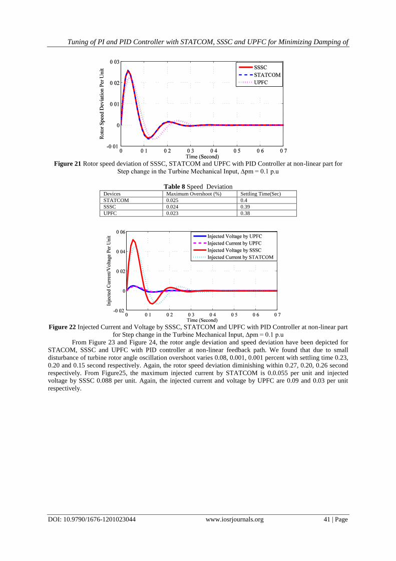
Figure 21 Rotor speed deviation of SSSC, STATCOM and UPFC with PID Controller at non-linear part for
Step change in the Turbine Mechanical Input, ∆pm = 0.1 p.u
Table 8 Speed Deviation Devices Maximum Overshoot (%) Settling Time(Sec)
STATCOM 0.025 0.4
SSSC 0.024 0.39
UPFC 0.023 0.38
Figure 22 Injected Current and Voltage by SSSC, STATCOM and UPFC with PID Controller at non-linear part
for Step change in the Turbine Mechanical Input, ∆pm = 0.1 p.u
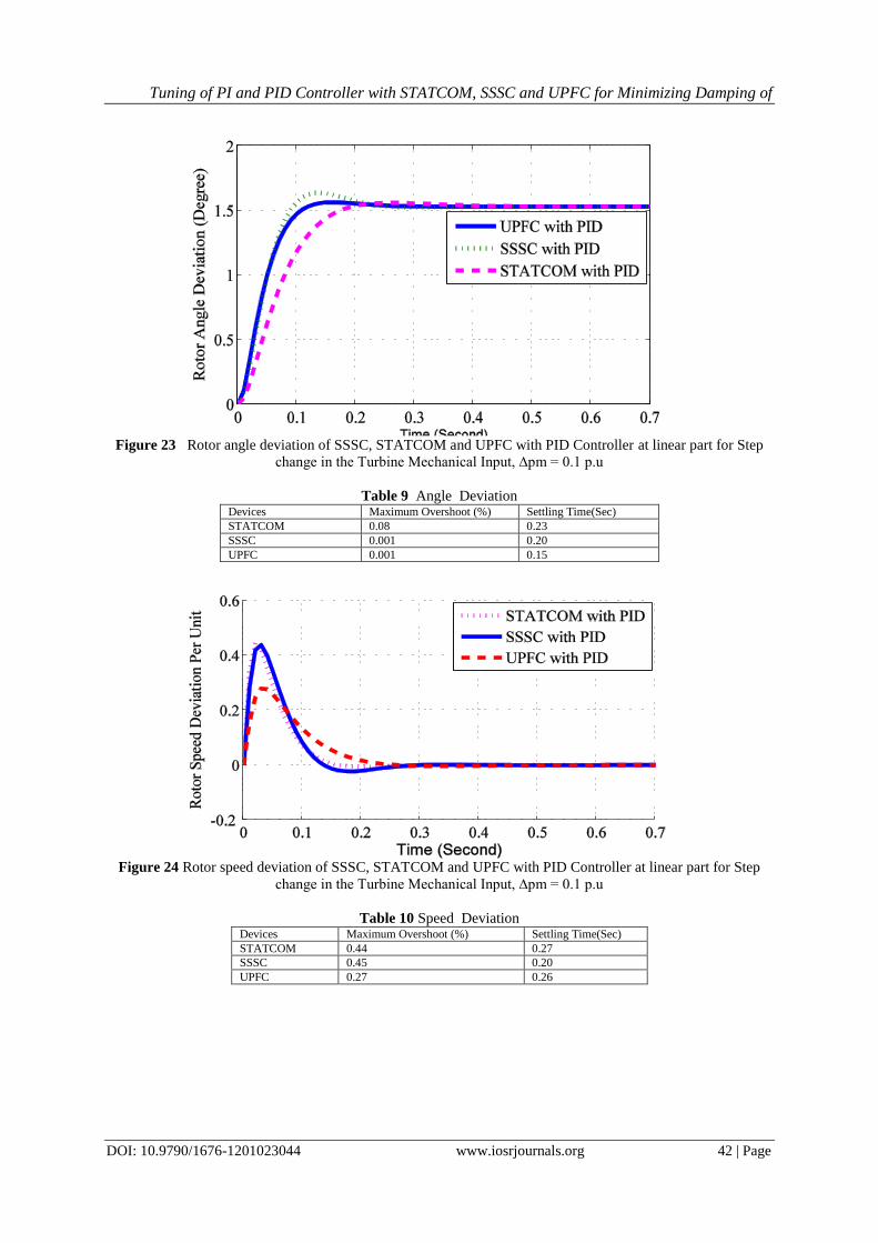
From Figure 23 and Figure 24, the rotor angle deviation and speed deviation have been depicted for
STACOM, SSSC and UPFC with PID controller at non-linear feedback path. We found that due to small
disturbance of turbine rotor angle oscillation overshoot varies 0.08, 0.001, 0.001 percent with settling time 0.23,
0.20 and 0.15 second respectively. Again, the rotor speed deviation diminishing within 0.27, 0.20, 0.26 second
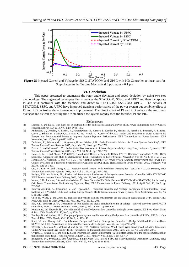
respectively. From Figure25, the maximum injected current by STATCOM is 0.0.055 per unit and injected
voltage by SSSC 0.088 per unit. Again, the injected current and voltage by UPFC are 0.09 and 0.03 per unit
respectively.
Tuning of PI and PID Controller with STATCOM, SSSC and UPFC for Minimizing Damping of
DOI: 10.9790/1676-1201023044 www.iosrjournals.org 42 | Page
Figure 23 Rotor angle deviation of SSSC, STATCOM and UPFC with PID Controller at linear part for Step
change in the Turbine Mechanical Input, ∆pm = 0.1 p.u
Table 9 Angle Deviation Devices Maximum Overshoot (%) Settling Time(Sec)
STATCOM 0.08 0.23
SSSC 0.001 0.20
UPFC 0.001 0.15
Figure 24 Rotor speed deviation of SSSC, STATCOM and UPFC with PID Controller at linear part for Step
change in the Turbine Mechanical Input, ∆pm = 0.1 p.u
Table 10 Speed Deviation Devices Maximum Overshoot (%) Settling Time(Sec)
STATCOM 0.44 0.27
SSSC 0.45 0.20
UPFC 0.27 0.26
Tuning of PI and PID Controller with STATCOM, SSSC and UPFC for Minimizing Damping of
DOI: 10.9790/1676-1201023044 www.iosrjournals.org 43 | Page
Figure 25 Injected Current and Voltage by SSSC, STATCOM and UPFC with PID Controller at linear part for
Step change in the Turbine Mechanical Input, ∆pm = 0.1 p.u
VI. Conclusion This paper presented to enumerate the rotor angle deviation and speed deviation by using two-step
methodology. The suggested techniques first simulates the STATCOM, SSSC, and UPFC and then incorporate
PI and PID controller with the feedback and direct to STATCOM, SSSC and UPFC. The actions of
STATCOM, SSSC, and UPFC have improved transient performance of the power system but combine effect of
PI and PID controller show tremendous improvement. The direct effect of PI and PID enhance the maximum
overshot and as well as settling time to stabilized the system rapidly then the feedback PI and PID.
References [1] Larsson, S. and Ek, E., The black-out in southern Sweden and eastern Denmark, inProc. IEEE Power Engineering Society General
Meeting, Denver, CO, 2013, vol. 2, pp. 1668–1672.
[2] Andersson, G., Donalek, P., Farmer, R., Hatziargyriou, N., Kamwa, I., Kundur, P., Martins, N., Paserba, J., Pourbeik, P., Sanchez-
Gasca, J. Schulz, R., Stankovic,A., Taylor, C. and Vittal, V. , Causes of the 2003 Major Grid Blackouts in North America and Europe, and Recommended Means to Improve System Dynamic Performance, IEEE Transactions on Power Systems, 2005,
November, Vol. 20, No. 4, pp-1922-1928.
[3] Dmitrova, E., Wittrock,M.L., Jóhannsson,H. and Nielsen,A.H., Early Prevention Method for Power System Instability‟, IEEE Transactions on Power Systems, 2015, July, Vol. 30, No.4, pp-1784-1792.
[4] Preece, R. and Milanović, J.V. , Probabilistic Risk Assessment of Rotor Angle Instability Using Fuzzy Inference Systems‟, IEEE
Transactions on Power Systems, 2015, July, Vol. 30, No.4, pp-1747-1757 [5] Deng, J., Li, C. and Zhang, X.P. (2015), „Coordinated Design of Multiple Robust FACTS Damping Controllers: A BMI-Based
Sequential Approach with Multi-Model Systems‟, IEEE Transactions on Power Systems, November, Vol. 30, No. 6, pp-3150-3159.
[6] Johansson,N., Ängquist, L. and Nee, H.P. , An Adaptive Controller for Power System Stability Improvement and Power Flow Control by Means of a Thyristor Switched Series Capacitor (TSSC), IEEE Transactions on Power Systems, 2010, February, Vol.
25, No. 1,pp-381-391.
[7] Gui, Y., Kim, W. and Chung, C.C. , Passivity-Based Control With Nonlinear Damping for Type 2 STATCOM Systems, IEEE Transactions on Power Systems, 2016, July, Vol. 31, No. 4, pp-2824-2833.
[8] Padiyar, K.R. and Prabhu, N. , Design and Performance Evaluation of Subsynchronous Damping Controller With STATCOM‟,
IEEE Transactions on Power Delivery,2006, July, Vol. 21, No. 3, pp-1398-1405. [9] Varma, R.K., Rahman, S.A. and Vanderheide, T. , New Control of PV Solar Farm as STATCOM (PV-STATCOM) for Increasing
Grid Power Transmission Limits during Night and Day, IEEE Transactions on Power Delivery, 2015, April Vol. 30, No. 2, pp-
755-763 [10] Kanchanaharuthai, A., Chankong, V. and Loparo,K.A. , Transient Stability and Voltage Regulation in Multimachine Power
Systems Vis-à-Vis STATCOM and Battery Energy Storage, IEEE Transactions on Power Systems, 2015, September, Vol. 30, No. 5, pp-2404-2016.
[11] Chen. H., Wang, Y. and Zhou, R., Transient and voltage stability enhancement via coordinated excitation and UPFC control‟, IEE
Proc. Gen. Tran. & Distr. 2001, May, Vol. 148, No.3, pp. 201-208. [12] Sen, K.K., and Keri, A.J.F., Comparison of field results and digital simulation results of voltage – sourced converter based FACTS
controllers, Trans. on Power Delivery , 2004, January, Vol. 18 No.1, pp.300-306.
[13] Kumkratug, and Haque,M.H. , Versatile model of a unified power flow controller in simple power system, IEE Proc. Gene. Trans. & Dist. 2003, March, Vol.150, No.2, pp.155-161.
[14] Tambey, N. and Kothari, M.L., Damping of power system oscillations with unified power flow controller (UPFC)‟, IEE Proc. Gen.
Tran. & Distr. 2003, March, Vol.150, No.2, pp 129-140. [15] Song, W. and. Huang, A.Q., Fault-Tolerant Design and Control Strategy for Cascaded H-Bridge Multilevel Converter-Based
STATCOM, IEEE Transactions on Industrial Electronics, 2010, August, Vol. 57, No. 8,pp-2700-2708
[16] Wessels,C., Molinas, M., Molinas,M. and Fuchs, F.W., StatCom Control at Wind Farms With Fixed-Speed Induction Generators Under Asymmetrical Grid Faults‟, IEEE Transactions on Industrial Electronics, 2013, July, Vol. 60, No. 7,pp-2864-2873.
[17] Gyugyi, L., Schauder, C. and Sen, K. Static Synchronous Series Compensator : A solid state approach to the series compensation of
transmission lines, IEEE Trans. on Power Delivery , 1997, January, Vol.12, No. 1, pp-406-417 [18] Bongiorno, M., Svensson,J. and Ängquist,L. Single-Phase VSC Based SSSC for Subsynchronous Resonance Damping, IEEE
Transactions on Power Delivery, 2008, July, Vol. 23, No. 3, pp-1544-1552.
Tuning of PI and PID Controller with STATCOM, SSSC and UPFC for Minimizing Damping of
DOI: 10.9790/1676-1201023044 www.iosrjournals.org 44 | Page
[19] Rai, D., . Faried,S.F. Ramakrishna,G. and Edris,A.A. , An SSSC-Based Hybrid Series Compensation Scheme Capable of Damping
Subsynchronous Resonance, IEEE Transactions on Power Delivery, 2012, April, Vol. 27, No. 2, pp-531-540
[20] Jiang, S. , Gole, A.M., Annakkage, U.D. and Jacobson, D.A. , Damping Performance Analysis of IPFC and UPFC Controllers Using Validated Small-Signal Models, IEEE Transactions on Power Delivery, 2011 ,January , Vol. 26, No. 1, pp-446-454.
[21] Hassan, L.H., Moghavvemi, M., Almurib, H. A. F. and Muttaqi, K.M., A Coordinated Design of PSSs and UPFC-based Stabilizer
Using Genetic Algorithm, IEEE Transactions on Industry Applications, 2014, September, Vol. 50, No. 5, pp-2957-2966. [22] Ghahnavieh, A.R., Firuzabad, M.F., Shahidehpour, M. and Feuillet, R., UPFC for Enhancing Power System Reliability, IEEE
Transactions on Power Delivery, 2010, October, Vol. 25, No. 4, pp-2881-2890.
[23] Liu Y., Yang, S., Wang, X., Gunasekaran, D., Karki, U. and Peng, F.Z. Application of Transformer-Less UPFC for Interconnecting Two Synchronous AC Grids With Large Phase Difference, IEEE Transactions on Power Electronics, 2016 Vol. 31, No. 9,pp-6092-
6103
[24] Ray, S.K., Sarker,P.C., Ahsan, M.C. Seddiqe,M.M.S.S, Novel Approach of PID Control Scheme with UPFC‟S for Damping of Oscillations‟, International Journal of Computer and Electrical Engineering, 2012, April, Vol.4, No.2, pp-104.109.
[25] Khorramabadi, S.S and Bakhshai, A. Critic-Based Self-Tuning PI Structure for Active and Reactive Power Control of VSCs in
Microgrid Systems, IEEE Transactions on Smart Grid, 2015, January, Vol. 6, No. 1, pp.92-103 [26] Sant,A.V; Rajagopal, K.R. and Sheth, N.K. Permanent Magnet Synchronous Motor Drive Using Hybrid PI Speed Controller With
Inherent and Noninherent Switching Functions‟, IEEE Transactions on Magnetics, 2011, October, Vol. 47, No. 10,pp.4088-4090.
[27] Martinez, A.R; Ramirez, R.G. and Vela-Valdes, L.G. PI Fuzzy Gain-Scheduling Speed Control at Startup of a Gas-Turbine Power Plant, IEEE Transactions on Energy Conversion, 2011, March, Vol. 26, No. 1,pp-310-317.
[28] Angle, L. and Viola, J. Design and Statistical Robustness Analysis of FOPID, IOPID and SIMC PID Controllers Applied to a
Motor Generator System, IEEE Latin America Transactions, December ,Vol. 13, No. 12,pp-3724-3734. [29] Ang, K.H., Chong, G. and Li, Y. (2005), „PID Control System Analysis, Design,and Technology‟, IEEE Transactions on Control
Systems Technology, , 2005, July, Vol. 13, No. 4, pp-559-576.
[30] Lee, J.Y., Jin, M. and Chang, P.H. Variable PID Gain Tuning Method Using Backstepping Control With Time-Delay Estimation and Nonlinear Damping, IEEE Transactions on Industrial Electronics, 2014, December, Vol. 61, No. 12, pp-6975-6985.
[31] Seddiqe, M.M.I.S, Ray, S.K. Application of SDGM to Digital PID and Performance Comparison with Analog PID Controller,
International Journal of Computer and Electrical Engineering, October, Vol. 3, No. 5, 2011, pp-634-638. [32] Ray, S.K. and Paul D. Performance Comparison of Electronic Printwheel System by PI and PID Controller Using Genetic
Algorithms, International Journal of Computer Science & Emerging Technologies, December, Vol. 1, No.4, 2010 pp-200-207
[33] Saadat,H Power System Analysis,, 3rd ed., New York. .(1999),


