

Water management for the
Pharmaceutical Industry
2E200- Version 001 – Date 22.03.2012

Water is the most important natural resource worldwide. Water, treated to drinking water quality, is the
number one foodstuff. Water is also the basic carrier for pharmaceutical processes and products.
Water is our core competence
Being a leading manufacturer, we develop and produce systems for process and ultrapure water
treatment, waste water treatment, and water and resource recovery.
We supply:
● Raw water pretreatment
● Production, storage and distribution of PW, HPW, WFI and pure steam
● Loop systems
● Process plants
● Waste water treatment
● Automation systems
● Qualification and documentation in accordance with cGMP
We provide pragmatic solutions for pharmaceutical applications, both as standard compact systems
which operate reliably thanks to their perfected and innovative technology, and as individual systems
offering standardised processes of the highest quality – combined flexibly according to market- and
customer-specific requirements.
Satisfying customer requests
As a dependable partner, we support our customers throughout the life cycle of their plants, from
consulting and basic engineering, construction of the system, delivery and installation on the site,
commissioning, qualification, through to after-sales service.
SH + E Group services create trust and give safety assurances. You can choose from demand-oriented
after-sales service through to full service offerings, including spare parts and chemicals management.
Analyses carried out in our in-house laboratory are also part of our range of services, in addition to
servicing, maintenance and calibration.
We develop forward-looking concepts according to the latest state of the art for you which:
● Minimise the water requirement
● Increase the availability
● Improve the water quality
● Conserve energy
● Cut costs
Take us by our word
Water in its purest form

For the production of water for pharmaceutical applications, the pharmacopoeias require water of
drinking water quality as the basic material. In addition, our plant design is based on the following
standard conditions:
Should the raw water not meet these conditions, additional raw water treatment stages may be
necessary.
Pharma water qualities
The different pharma water qualities are defined in the pharmacopoeias:
European Pharmacopoeia (EP)
● Purified Water ( Aqua purificata)
● Highly Purified Water (Aqua valde purificata)
● Water for Injection ( Aqua ad iniectabile)
United States Pharmacopoeia (USP)
● Purified Water (PW)
● Water for Injection (WFI)
Purified Water (PW, Aqua Purificata - AP) is water for the preparation of medicines other than those
that are required to be both sterile and apyrogenic, unless otherwise justified and authorised.
Water for Injection (WFI) is water for the preparation of medicines for parenteral administration
when water is used as vehicle (water for injection in bulk) and for dissolving or diluting of substances or
preparations for parenteral administration (sterilised water for injection).
Highly Purified Water (HPW) is intended for the use in the preparation of the medicinal products
where water of high biological quality is needed, except where Water for Injection is required.
Requirements / Guidelines
Drinking Water acc. to TrinkwV 2001
Conductivity < 1,000 µS/cm
Total Hardness < 20 °dH
Iron < 0.05 ppm
Manganese < 0.05 ppm
Silica SiO2 < 20 ppm
Total Organic Carbon TOC < 2 ppm
Silt Density Index SDI 15 < 3
Others free of oxidantes

The quality of pharma water for the production of drugs and active agents is defined
in the United States, European and other country-specific pharmacopoeias:
Requirements / Guidelines
Purified Water (PW) European Pharmacopeia US Pharmacopeia
Production processIon exchange,
membrane process
Ion exchange,
membrane process
Electr. conductivity ≤ 4.3 µS/cm (20°C)≤ 1.1 µS/cm (20°C)
downstream of Stage 1
TOC ≤ 500 ppb ≤ 500 ppb
Nitrate ≤ 0.2 ppm -
Heavy metals ≤ 0.1 ppm -
Colony-forming units ≤ 100 CFU/ml ≤ 100 CFU/ml
Water for Injection (WFI)
Production process DistillationDistillation or
membrane process
Electr. conductivity ≤ 1.1 µS/cm (20°C) ≤ 1.1 µS/cm (20°C)
TOC ≤ 500 ppb < 500 ppb
Nitrate ≤ 0.2 ppm -
Heavy metals ≤ 0.1 ppm -
Colony-forming units ≤ 10 CFU/ 100 ml -
Bacterial endotoxins ≤ 0.25 EU/ml ≤ 0.25 EU/ml
Highly Purified Water (HPW)
Production process membrane process -
Quality same as WFI -

Water for Injection
Purified Water
(Aqua Purificata) Pure Steam
Highly Purified
Water
Drinking water
Demineralisation /
Reduction of TOC
Electro-deionisation
Reverse Osmosis
Ion-exchange
Removal of Pyrogens
Distillation
Ultrafiltration
Guidelines for the design and implementation of a pharma water treatment plant:
Pharma water is produced by the following steps:
● GAMP
● ISPE Baselines
● Water qualities /
analysis methods
● FDA regulations
● European Commission (EG)
● Company-specific instructions
● PIC/S
● USP (current version)
● European Pharmacopoeia (EP current version)
● Guide to Inspection of High-Purity Water Systems
● 21 CFR 210/211, 21 CFR Part 11, 21 CFR 177
● Annex 15 to the EU Guide to
Good Manufacturing Practice
● Guide to Good Manufacturing Practice for
Medicinal Products
● Pharmaceutical Engineering Guides.
Volume 4 Water and Steam Systems
● Guide for Validation of Automated Systems
Only USP and JP
Requirements / Guidelines

Raw water pretreatment
Water treatment plants have to be protected against problematic components in the raw water to
ensure dependable operation. These include iron, manganese, free chlorine, organic material or
colloidal suspended solids.
These substances can cause malfunctions and have therefore to be eliminated from the raw water.
Different processes are used, depending on the raw water quality:
● Raw water ultrafiltration
● Sand or gravel filters
● Multimedia filters
● Activated carbon filters
● UV oxidation / UV sterilisation
● Chemicals dosing stations
A careful analysis of the existing raw water quality is crucial. Experienced staff determine the optimum
process steps on the basis of the available data. Dependability, cost effectiveness and operator
convenience are the focus of our designs.

Raw water pretreatment
● Optimum pretreatment for the downstream ROCEDIS
● Reduction of the silt density index SDI
● Reduction of bacteria
● Reduction of nutrients (TOC)
● Modular design, easy to upgrade
The ULTRALIS ultrafiltration plant effectively eliminates colloidal matters (e.g. corrosion products).
Unlike conventional multimedia filters, the ultrafiltration plant also retains bacteria, endotoxins and
colloidal silica. The silt density index SDI15 of the raw water is reduced to less than 3, and the bacterial
count in the treated raw water is reduced by a factor of 1000. Our ULTRALIS is operated by the dead-
end process, i.e. the entire raw water fed in is filtered through the membrane. The UF membrane is
backwashed and sterilised automatically, adapted to the respective raw water conditions.
Advantages
Skid
To
PW generation
PI
PI
PISA
NaOCl
LIS
FISA
Waste
PI
LISA
PISA
FSA
PIQISA
Redox
Drinking
water
P
P
UF ModulsBackwash
pump
Filtrate
pump
Filtrate
tankDosing station
Backwash
filter
Pipe
separator
Skid
To
PW generation
PI
PI
PISA
NaOCl
LIS
FISA
Waste
PI
LISA
PISA
FSA
PIQISA
Redox
Drinking
water
P
P
UF ModulsBackwash
pump
Filtrate
pump
Filtrate
tankDosing station
Backwash
filter
Pipe
separator
Skid
To
PW generation
PIPI
PIPI
PISAPISA
NaOCl
LISLIS
FISAFISA
Waste
PIPI
LISALISA
PISAPISA
FSAFSA
PIPIQISAQISA
Redox
Drinking
water
PP
PP
UF ModulsBackwash
pump
Filtrate
pump
Filtrate
tankDosing station
Backwash
filter
Pipe
separator

Models
ULTRALIS is delivered as a compact plant, pre-assembled on a rack, comprising:
● Input control valve to set a constant filtrate flow
● Connection for an SDI meter
● Backwash-type 100 µm protective filter
● Ultrafiltration modules as hollow-fibre modules with a separation limit
of 100,000 MW (molecular weight)
● Low-noise centrifugal pumps of stainless steel/grey cast iron for operation
and backwashing
● Filtrate tank as a PE circular tank to hold the backwashing water,
designed with a sloping bottom, spray ball and inspection opening
● Dosing station for NaOCl
● Flow meters for filtrate, backwashing water and chemical
● Pressure gauges for filtrate and concentrate
● Piping of PVC
● Rack of stainless steel with level elements
● Autonomous switch cabinet with own control system via Siemens SPS S7-ET200S
Raw water pretreatment
ULTRALIS 2000 4000 8000 12000
Capacity (filtrate) m³/h 2.0 4.0 8.0 12.0
Filter area m² 30 50 100 150
Capacity of backwash pump at 2.5 bar m³/h 10 15 30 45
Capacity of filtrate pump at 5 bar m³/h 3 5 10 15
Volume of filtrate tank m³ 1.1 3 6 9
Mechanical connections
Raw water DN 25 32 40 50
Filtrate DN 20 25 32 40
Back-flushing / waste water DN 40 50 80 100
Electrical connections
Backwsh pump kW 1.1 2.2 4.0 5.0
Filtrate pump kW 0.8 1.5 2.2 4
Dimensions of UF Skid
Width mm 2,500 2,500 2,900 2,900
Depth mm 1,500 1,500 2,100 2,100
Height mm 2,100 2,100 2,000 2,200
Dimensions of filtrate tank
Diameter mm 1,400 1,400 1,800 2,000
Total height approx. mm 1,800 2,400 2,800 3,400
Weight without tank
Net weight approx. kg 800 1,000 1,200 1,500

Softening
Softeners are an elementary process component of a water treatment plant for the production of highly
purified water in accordance with USP/EP. The perfect and reliable functioning of the downstream
membrane processes such as reverse osmosis and electrodeionisation can only be ensured by the
complete elimination of the hardness components calcium and magnesium contained in the raw water.
We offer two alternative designs:
PHARMASOFT
a volume-controlled softener with a central control valve and concurrent regeneration
ECOSOFT
a volume-controlled softener with a single valve control and salt- and water-conserving counter-current
regeneration
The advantages our softeners offer are their fail-safe and cost-effective operation. Their connection in
series provides a highly reliable protection against hardness breakthroughs. Additionally, hardness
breakthroughs are detected by an optional residual hardness meter. Short regeneration cycles, high
flow rates and continuous flow through the resin beds result in a minimisation of the microbial growth
potential in normal operation. The microbiology in the resin bed is controlled by regular automatic
sanitisations with chemicals, hot water (80°C) or hot brine (60°C).
Our PHARMASOFT has been designed as an automatic duplex softener with concurrent regeneration.
The start of the automatic regeneration cycle is volume-controlled by a water meter. The unit is
chemically sanitised.
With the PHARMASOFT TS, the microbiology in the resin beds is effectively destroyed periodically by
sanitisation with hot water. The sanitisation interval can be shortened or extended as required.
Sanitisation with hot water is carried out via the electric heater or steam-heated heat exchanger of the
downstream ROCEDIS. The exchange resin tanks and the piping of the PHARMASOFT TS are made
of 316L stainless steel.
PI
Drinking
water
NaCl
PI°dH
QISA
FQS
To
ROCEDIS
Skid
NaCl
P
Softener 1
Brine tank 1
Protection
filter
Pipe
separator
Brine tank 2
Softener 2
PIPI
Drinking
water
NaCl
PIPI°dH
QISA
FQS
To
ROCEDIS
Skid
NaCl
PP
Softener 1
Brine tank 1
Protection
filter
Pipe
separator
Brine tank 2
Softener 2

Like all our softeners, the PHARMASOFT is also delivered as a compact plant on a stainless steel
rack, preassembled and wired:
● Raw water protective filter, 100 µm
● Pipe separator
● Two FRP exchange vessels
● Option: 316L stainless steel exchange vessels for thermal sanitisation
● Two central control valves for the 5-stage regeneration process
● Two fillings of high-performance ion exchange resin
● Two PE brine preparation tanks with the necessary internals
● Equipment for chemical sanitisation
● Option: Equipment for thermal sanitisation with hot water (> 80°C)
● Water flow meter with contact
● Option: Residual hardness measurement TESTOMAT 2000
● Piping in PP or 316L stainless steel
● Stainless steel rack and level elements
● Control via common switch cabinet of ROCEDIS
Softening
PHARMASOFT (TS) 200 300 400 500 600 700
Softwater l/h 750 2,250 4,500 7,400 8,800 11,800
Feed (max.) l/h 1,100 3,200 6,100 11,300 15,200 24,600
Capacity °dH 105 260 560 850 1,180 1,550
Salt demand kg/ Reg. 7 17 36 56 77 101
Waste l/ Reg. 190 500 900 1,600 2,000 3,800
Mechanical connections
Feed DN 25 25 40 50 50 50
Soft water DN 25 25 40 50 50 50
Dimensions incl. Brine tank
Width mm 1,500 1,500 1,500 2,000 2,500 2,500
Depth mm 800 800 1,000 1,200 1,500 1,700
Height mm 2,000 2,300 2,300 2,400 2,400 2,400
Volume of each brine tank Liter 200 200 400 750 750 1,000
Weight
Net weight PHARMASOFT approx. kg 300 350 350 400 400 450
Net weight PHARMASOFT TS approx. kg 450 500 500 550 550 650
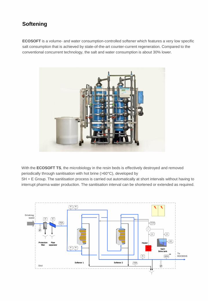
ECOSOFT is a volume- and water consumption-controlled softener which features a very low specific
salt consumption that is achieved by state-of-the-art counter-current regeneration. Compared to the
conventional concurrent technology, the salt and water consumption is about 30% lower.
With the ECOSOFT TS, the microbiology in the resin beds is effectively destroyed and removed
periodically through sanitisation with hot brine (>60°C), developed by
SH + E Group. The sanitisation process is carried out automatically at short intervals without having to
interrupt pharma water production. The sanitisation interval can be shortened or extended as required.
Softening
°dH
QISA
FQS
To
ROCEDIS
Skid
NaCl
Brine tank
FI PI
PI PI
P
FI PI
P
FIFI
LS
PI
Protection
filter
Pipe
separatorHeater
TISA
TICSA
Drinking
water
Softener 2Softener 1
°dH
QISA
FQS
To
ROCEDIS
Skid
NaCl
Brine tank
FIFI PIPI
PIPI PIPI
PP
FIFI PIPI
PP
FIFIFIFI
LSLS
PIPI
Protection
filter
Pipe
separatorHeater
TISA
TICSATICSA
Drinking
water
Softener 2Softener 1

Softening
● Low salt and water consumption thanks to state-of-the-art countercurrent technology
● Automatic start of the sanitisation cycle after every xth regeneration
● High sanitisation effect as a result of the combination of high temperature (> 60°C) and brine
treatment
● PW production not interrupted during sanitisation of a softener column
● No corrosion problem thanks to the design of plastic material (maximum temperature 65°C)
The ECOSOFT TS softener is delivered as a compact unit, preassembled and wired:
● Raw water protective filter, 100 µm
● Pipe separator
● Two FRP exchange vessels
● PP pneumatic diaphragm valves
● Two fillings of high-performance ion exchange resin
● One PE brine preparation tank with the required internals
● Equipment for chemical sanitisation
● Electric heater or steam-heated plate heat exchanger for thermal sanitisation
with hot brine (> 60°C)
● Contact-type water meter
● Option: Residual hardness measurement TESTOMAT 2000
● Piping in PP
● Stainless steel rack with level elements
● Autonomous switch cabinet with own control system via SPS Siemens S7-ET200S
ECOSOFT (TS) 300 400 500 600 700 900
Softwater l/h 2,250 4,400 8,000 10,900 15,000 25,400
Feed (max.) l/h 3,300 6,100 11,300 15,200 22,000 35,600
Capacity °dH*m² 200 450 820 1,170 1,840 2,600
Salt demand kg/ Reg. 8 16 29 42 66 93
Waste l 400 800 1,400 2,000 3,100 4,500
Mechanical connections
Feed DN 25 32 50 65 65 80
Soft water DN 25 32 40 50 50 65
Thermal Sanitisation for ECOSOFT TS
Electr. Heater kW 25
Steam-heated heat exchanger kW 30 60 80 130 200
Steam demand (120°C @ 2 bar) kg/h 55 100 140 225 310
Dimensions incl. Brine tank
Width mm 2,900 2,900 2,900 3,050 3,050 3,550
Depth mm 1,200 1,200 1,250 1,400 1,500 1,900
Height mm 2,300 2,500 2,500 2,750 2,750 3,000
Volume of brine tank l 200 200 300 400 500 1,000
Weight
Net weight approx. kg 350 400 400 450 500 600

PW and HPW generation
Purified Water (PW) is produced from softened water by a combination of a reverse osmosis and
electro-deionisation (ROCEDIS) process. Most of the demineralisation takes place in a reverse
osmosis (RO) system, where water components such as salts, TOC, particles, bacteria and pyrogens
are retained on the surface of a semi-permeable membrane. Electro-deionisation (CEDI) is an electro-
chemical membrane process which demineralises the reverse osmosis permeate continuously to the
very low conductivity required for highly purified water. The values remain significantly below those
required by the pharmacopoeias.
Depending on the composition of the raw water, a chemical-free membrane degasser is added to the
ROCEDIS to remove the free carbon dioxide.
For the production of Highly Purified Water (HPW), an ultrafiltration unit is connected downstream of
the ROCEDIS. Ultrafiltration serves as the last process step for the safe removal of bacteria and
pyrogens. An excellent microbiological water quality is achieved as a result of the integral structural
design and the separation efficiency of 6000 MW.
● Constantly high HPW quality according to USP / EP
● Reduction of bacteria and pyrogens
● Chemicals-free operation
● High water yield
● Comfortable sampling by means of a sampling panel
● Compact, little space required
● Easy to add-on thanks to the modular design

The ROCEDIS is delivered as a compact unit in FDA/GMP-compliant pharma design, ready for
connection, preassembled and wired:
● Protective filter, 5 µm
● Automatic inlet valve for safety shutdown
● Control valve or pressure reducer to maintain a constant feed pressure
● Low-noise high-pressure pump in 316 stainless steel, with frequency innverter
● RO pressure pipes in FRP or 316L
● Membrane elements of energy-conserving ultralow pressure design
● Option: Membrane degasser for CO2 removal
● EDI stacks of pressure-resistant, leak-free pharma design
● Option: EDI stack of hot-water resistant design
● Option: Downstream ultrafiltration unit for HPW production
● Pharma safety valve to protect the EDI from pressure surges
● Sterile sampling after each process step
● High-quality conductivity meters downstream of RO and EDI (Mettler)
● Pressure and temperature transmitters
● System piping in polypropylene or stainless steel
● Pipes in contact with the product from the outlet of the RO or EDI in 316L, Ra ≤ 0.8 µm
● Option: Pipes in contact with the product after the last process step in
316L, e-polished (Ra ≤ 0.6 µm) and ferrite content <1% / <3%
● Discard circuit quality-controlled for secure HPW output
● Autonomous switch cabinet with own control system via Siemens SPS S7-ET200S
● Touch panel Siemens MP377, 15“
The ROCEDIS.eco concept enables a maximum water yield (WCF) through the entire process chain
with unlimited availability. The patented SB Plus and recycling concept not only saves drinking water,
but also reduces the salt requirement of the upstream softener.
You can choose between different cGMP-compliant alternatives:
● ROCEDIS PW-PP – Generation of PW,
basic material polypropylene, except pipework in contact with the product in 316L stainless
steel, chemically sanitisable
● ROCEDIS PW-SS – Generation of PW,
totally 316L stainless steel, chemically sanitisable
● ROCEDIS PW-TS – Generation of PW,
totally 316L stainless steel, thermally sanitisable
● ROCEDIS HPW-TS – Generation of HPW,
totally 316L stainless steel, with UF connected downstream, thermally sanitisable
PW and HPW generation

Our cost-effective basic model ROCEDIS PW-PP for PW generation:
● Piping of PP
● Pipes coming into contact with the product from the EDI outlet of 316L
● Chemical sanitisation via a dosing pump
● Low capital costs
PW generation
ROCEDIS PW-PP
Product capacity (PW) l/h
Soft water feed l/h
Softening
Mechanical connections
Soft water (flange DIN EN 1092-1) DN
Product (clamp nozzle DIN 32676) DN
Waste water (pipe end, HT-PP) DN
Electrical connection
Electr. connection of system kW
Dimensions of Skid
Width mm
Depth mm
Height mm
Weight
Net weight approx. kg
ROCEDIS PW-PP
Product capacity (PW) l/h
Soft water feed l/h
Softening l/h
Mechanical connections
Soft water (flange DIN EN 1092-1) DN
Product (clamp nozzle DIN 32676) DN
Waste water (pipe end, HT-PP) DN
Electrical connection
Electr. connection of system kW
Dimensions of Skid
Width mm
Depth mm
Height mm
Weight
Net weight approx. kg
10000 12000
6,0
7,8
8,0
10,3
10,0 12,0
12,9 15,5
3.800
2.000
2.300
50
40
100
50
40
100
1,300
2,300
900 1,200
1.500 1.800 1.900
separate rack separate rack
1.600
18 24
2.800
2.300
separate rack
25
15
100
40
25
100
3,000 4,000
700 1,400 2,100 2,800 4,200 5,500
1,500 2,000
6 12
2,800 2,800
500 1000 1500
500 1,000
2000 3000
integrated
6000
1,300
2,300
8000
4000
Air
Skid
To
Storage
tank
From
Softener PI
PS-
PI
PS+µS/cm
PI
FICSA
TI
QISA
FI FI
PISAPI
LIS
Membrane
degasifier
(Option)
Reverse
OsmosisRO High
pressure pumpPrefilter
5 µm
PPP
Dosing
pump for
chemical
sanitisation
FU
PP 316L
TI
QISA
PI
PI
FISA
P P
µS/cm
EDI
PI
FISA
PISA
Air
Skid
To
Storage
tank
From
Softener PIPI
PS-
PIPI
PS+µS/cm
PIPI
FICSAFICSA
TITI
QISA
FIFI FIFI
PISAPISAPIPI
LISLIS
Membrane
degasifier
(Option)
Reverse
OsmosisRO High
pressure pumpPrefilter
5 µm
PPPPPP
Dosing
pump for
chemical
sanitisation
FU
PP 316L
TITI
QISA
PIPI
PIPI
FISAFISA
PP PP
µS/cm
EDI
PIPI
FISAFISA
PISAPISA

Our ROCEDIS PW-SS/TS for demanding applications:
● Piping totally 316L stainless steel
● Chemical sanitisation
● Option: Thermal sanitisation by means of an electric continuous-flow heater or
steam-heated heat exchanger
PW Generation
ROCEDIS PW-SS/TS
Product capacity (PW) l/h
Soft water feed l/h
Softening
Mechanical connections
Soft water (flange DIN EN 1092-1) DN
Product (clamp nozzle DIN 32676) DN
Waste water DN
Electrical connection
Electr. connection of system kW
Thermal Sanitisation
Electrical heater kW
Dimensions
Width mm
Depth mm
Height mm
Weight
Net weight approx. kg
ROCEDIS PW-SS/TS
Product capacity (PW) l/h
Soft water feed l/h
Softening l/h
Mechanical connections
Soft water (flange DIN EN 1092-1) DN
Product (clamp nozzle DIN 32676) DN
Waste water DN
Electrical connection
Electr. connection of system kW
Thermal Sanitisation
Steam-heated heat exchanger kW
Steam demand (2 bar, 120°C) kW
Dimensions
Width mm
Depth mm
Height mm
Weight
Net weight approx. kg
15,500
100
70
12000
6,000
7,800
8,000
10,300
10,000 12,000
12,900
1,000 1,400
140
10000
18 24
50
40
100
50
separate rack separate rack
1,600
40
3,800
100 120
220 250130 180
25
15
100
2,800
6000
1,300
2,300
4000
6 12
700 1,400 2,100 2,800
40
25
100
2000 3000
integrated
10
1,500
4,200
500 1000 1500
500 1,000
1,300
2,300
15 20
2,800
2,000 3,000
separate rack
30 40
4,000
5,500
20
8000
2,000
2,300
1,700 2,100 2,200
2,300
2,800
From
Softener
Air
Skid
PI
PS-
PI
PS+µS/cm
PI
FICSA
TI
QISA
FI FI
PISAPI
LIS
PPP
Chemical
Sanitisation
FU
TI
QISA
PI
PI
FISA
P P
µS/cm
PI
FISA
PISA
Membrane
degasser
(Option)
Reverse
OsmosisRO High
pressure pumpPrefilter
5 µm EDI
To
Storage
tank
From
Softener
Air
Skid
PIPI
PS-
PIPI
PS+µS/cm
PIPI
FICSAFICSA
TITI
QISA
FIFI FIFI
PISAPISAPIPI
LISLIS
PPPPPP
Chemical
Sanitisation
FU
TITI
QISA
PIPI
PIPI
FISAFISA
PP PP
µS/cm
PIPI
FISAFISA
PISAPISA
Membrane
degasser
(Option)
Reverse
OsmosisRO High
pressure pumpPrefilter
5 µm EDI
To
Storage
tank
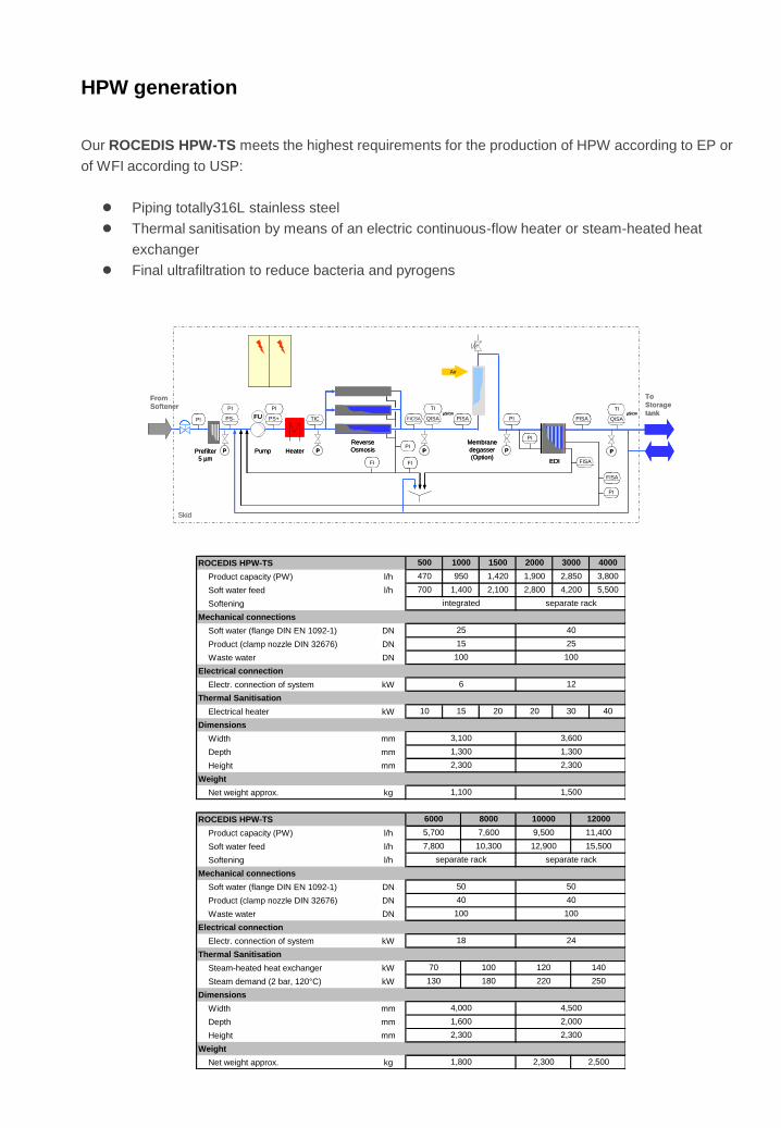
Our ROCEDIS HPW-TS meets the highest requirements for the production of HPW according to EP or
of WFI according to USP:
● Piping totally316L stainless steel
● Thermal sanitisation by means of an electric continuous-flow heater or steam-heated heat
exchanger
● Final ultrafiltration to reduce bacteria and pyrogens
HPW generation
ROCEDIS HPW-TS
Product capacity (PW) l/h
Soft water feed l/h
Softening
Mechanical connections
Soft water (flange DIN EN 1092-1) DN
Product (clamp nozzle DIN 32676) DN
Waste water DN
Electrical connection
Electr. connection of system kW
Thermal Sanitisation
Electrical heater kW
Dimensions
Width mm
Depth mm
Height mm
Weight
Net weight approx. kg
ROCEDIS HPW-TS
Product capacity (PW) l/h
Soft water feed l/h
Softening l/h
Mechanical connections
Soft water (flange DIN EN 1092-1) DN
Product (clamp nozzle DIN 32676) DN
Waste water DN
Electrical connection
Electr. connection of system kW
Thermal Sanitisation
Steam-heated heat exchanger kW
Steam demand (2 bar, 120°C) kW
Dimensions
Width mm
Depth mm
Height mm
Weight
Net weight approx. kg
4,000
2,000
2,300
1,800 2,300 2,500
2,300
40
3,800
5,500
20
950
1,300
2,300
15 20
3,600
1,900 2,850
separate rack
30
2000 3000
integrated
10
1,420
4,200
500 1000 1500
470
4000
6 12
700 1,400 2,100 2,800
40
25
100
130 180
25
15
100
3,100
6000
1,300
2,300
8000
50
separate rack separate rack
1,600
40
4,500
100 120
220 250
12,900
1,100 1,500
140
10000
18 24
50
40
100
15,500
100
70
12000
5,700
7,800
7,600
10,300
9,500 11,400
Skid
PI
PS-
PI
PS+ TICµS/cm
PI
FICSA
TI
QISA
FI FI
PISA
TI
QISA
PI
PI
FISA
PI
PPPP P
µS/cmFU PI
FISA
PISA
From
Softener
Air
Membrane
degasser
(Option)
Reverse
OsmosisPumpPrefilter
5 µm EDI
To
Storage
tank
Heater
Skid
PIPI
PS-
PIPI
PS+ TICTICµS/cm
PIPI
FICSAFICSA
TITI
QISA
FIFI FIFI
PISAPISA
TITI
QISA
PIPI
PIPI
FISAFISA
PIPI
PPPPPPPP PP
µS/cmFU PIPI
FISAFISA
PISAPISA
From
Softener
Air
Membrane
degasser
(Option)
Reverse
OsmosisPumpPrefilter
5 µm EDI
To
Storage
tank
Heater

The DESTOMAT multiple effect water still with its unique falling-film evaporation technology features an
innovative patented column design and enhanced process technology and offers an even higher output,
energy efficiency and dependability. The DESTOMAT WFI generation unit is supplied with purified
water from our ROCEDIS units. This prevents hazardous water components such as hardness,
silicates, amines, chlorides, free carbon dioxide, TOC and conductivity from being fed in, ensuring
stable operation under safe compliance with USP, EP and JP for many years.
WFI generation
The distillation columns are equipped with
important new functions, thus ensuring
their suitability for different customer
requirements and operating environments.
Distillation against backpressure,
recirculation of non-evaporated feed water,
continuous blow-down measurement, the
possibility of self-sanitisation and
proportional control are just some of the
unique process features which are
available as options.
The core of the DESTOMAT distillation unit is the separation column – a falling-film evaporator of new
and compact design (patent applied for) which safely eliminates impurities through high velocities in
spiral-shaped baffle plates, an immediate phase transition from liquid to vapour state (flash evaporation)
and a reversal of the direction of flow. For effective gas elimination, the first column can be fitted with an
integrated gas separator as an option, while the subsequent columns have a gas outlet. The units are
equipped with a commercially available programmemable logic controller (PLC) from Siemens. An
operator panel from Siemens is installed to enable detection of the unit‘s current operating state or
intervention in the automatic operation of the unit.
● WFI production at a high temperature
● High energy utilisation
● Multi-stage separation
● Option: Simultaneous distillation and high-purity steam generation
● Option: Separation of non-condensable gases
● Option: Distillation against backpressure
● Option: Output control
● Easy to maintain
● FAT with simulation of the customer‘s operating media possible

The DESTOMAT by SH + E Group comprises the following components:
● Columns as pressure vessels with vent, drain, sight glass and level switch
● Pre-heater, evaporator, condenser and cooler of DTS design
● Insulation of the evaporator section of the columns, preheater
● Option: Gas separator with spray nozzle in the first column
● Feed water pump as a multi-stage centrifugal pump of SS 316 and buffer tank
● Safety pressure relief valve for heating steam pipe
● Pressure transducer for high-purity steam pressure control
● Flow meter for feed water
● 0.2 µm sterile filter in condenser vent pipe
● WFI conductivity meter (Mettler Toledo)
● Surfaces coming into contact with the product of 316L, mechanically polished,
Ra < 0.6 µm
● Seals FDA-compliant
● Vertically adjustable rack of coated steel
● Option: Rack of stainless steel
● Switch cabinet with Siemens SPS S7-300
● Touch panel Siemens SIMATIC TP177B
● Option: Colour touch panel Siemens SIMATIC MP277, 8“
● Option: Paper recorder or electronic recorder 21CFR Part 11-compliant
WFI generation
DESTOMAT 150 250 450 850 1600 2900 4700
Qty. of columns 4 or 5 4 or 5 4 to 6 4 to 6 5 to 7 5 to 8 6 to 8
WFI capacity at 4 bar l/h 160 210 535 1,010 2,175 3,743 6,520
WFI capacity at 6 bar l/h 195 295 725 1,385 2,900 4,880 8,636
WFI capacity at 8 bar l/h 225 380 890 1,670 3,450 6,000 10,750
Electrical connection
Electr. connection kW 1.0 1.0 1.0 1.5 3.0 4.0 5.0
Dimensions
Width max. * mm 1,400 1,400 2,890 2,890 4,450 5,100 5,630
Depth mm 980 980 860 860 1,100 1,100 1,750
Height mm 2,100 2,100 2,850 2,850 3,500 3,500 4,300
Distillate outlet mm 1,780 1,780 2,270 2,470 2,800 3,000 3,670
Weight
Net weight approx. * kg 700 900 1,500 1,900 3,150 5,000 6,250
* Width/ Weight at max. quantity of columns
LISALISA
FI
PW
Heating steam Condensate
WFI
TI
QISAµS/cm
TI
TI
Feed pump
Heater
Condenser
Feed tank
LISA
PI
TI TI
TI
PI
Blow Down Blow Down
PI
Reject
LISALISALISALISA
FIFI
PW
Heating steam Condensate
WFI
TITI
QISAµS/cm
TITI
TI
Feed pump
Heater
Condenser
Feed tank
LISALISA
PIPI
TITI TITI
TI
PI
Blow Down Blow Down
PIPI
Reject

Sterilisation processes in the pharmaceutical industry require high-quality Pure Steam (PS) with careful
pressure control and short supply time. In recent years, the removal of non-condensable gases has
become a major challenge for HP steam generators. The VAPOMAT HP steam generator meets these
requirements.
The VAPOMAT is supplied with purified water from our ROCEDIS units. The Pure Steam generator is
based on an innovative patented process that combines the advantages of the “thin falling film” and
“thermo-siphon” operating principles for the first time. Together with the standard proportional output
control, this results in very fast reaction times and a Pure Steam of the highest quality.
Pure Steam generation
● Rapid reaction to varying HP steam demands
● Proportional output control
● Continuously circulating hot feed water
● Multi-stage separation
● Continuous separation of non-condensable gases
● Option: Blow-down cooler
● No moving parts
● Low space requirement and low height
● FAT with simulation of the customer‘s operating media possible
The core of the VAPOMAT is a separator column
which safely removes pyrogens and other impurities
through high velocities, immediate phase transition
from liquid to vapour state (flash evaporation),
reversal of the direction of flow and centrifugal
separation via spiral-shaped baffle plates. Demisters
are not required. For an effective gas elimination, the
column is equipped with an integrated gas separator.
A unique feature is the continuous recycling of non-
evaporated feed water into the process (circulation).
This results in an efficient sanitisation of the piping
and a reduced feed water and heating steam
consumption.
The collection and continuous separation of the non-evaporated water droplets at the column bottom
ensures a constant quality, even if different volumes are drawn off.

The VAPOMAT is delivered as a compact unit in FDA/GMP-compliant pharma design, ready for
connection, preassembled and wired:
● Column as a pressure vessel with vent, drain, sight glass and level switch
● Column heat exchanger of DTS design
● Insulation of evaporator section of the column, preheater and circulation tank
● Feed water circulation pump as a multi-stage centrifugal pump in SS 316
● Circulation tank
● Safety pressure relief valve for heating steam pipe
● Pressure transducer for HP steam pressure control
● Option: Conductivity meter in the condensed HP steam and feed water
● Surfaces coming into contact with the product of 316L, mechanically polished,
Ra < 0.6 µm
● Seals FDA-compliant
● Vertically adjustable rack of steel, epoxy resin coated
● Option: Stainless steel rack
● Switch cabinet with Siemens SPS S7-300
● Touch panel Siemens TP177B, 4“
● Option: Paper recorder or electronic recorder 21CFR Part 11-compliant
Pure Steam generation
VAPOMAT 150 250 450 850 1600 2900 4700
Capacity at 6 bar heating steam kg/h 95 145 325 560 1,100 1,950 3,000
Capacity at 8 bar heating steam kg/h 130 210 490 830 1,650 2,950 4,550
Electrical connection
Electr. connection kW 0.55 0.55 1.0 1.0 1.5 3.0 4.0
Dimensions
Width mm 700 700 1,300 1,300 1,650 1,650 2,050
Depth mm 1,200 1,200 1,300 1,300 1,500 1,500 1,850
Height mm 2,000 2,000 2,300 2,700 3,100 3,500 4,100
Weight
Net weight approx. kg 235 265 420 560 835 1,160 1,655
FI
PW
Heating steam
Condenser
TI
QISAµS/cm
Heater Feed pump
LISA
Circulation
pump
Circulation
tank
Blow Down
PISA
PS
Gas
outlet
PI
PI
PIA
Sampling
FIFI
PW
Heating steam
Condenser
TITI
QISAµS/cm
Heater Feed pump
LISALISA
Circulation
pump
Circulation
tank
Blow Down
PISA
PS
Gas
outlet
PIPI
PIPI
PIAPIA
Sampling

You can choose between two sanitisation methods for storage and distribution:
SANICIRCLE - Cold operation with ozone / UV sanitisation
SANICIRCLE TS - Cold operation with periodic hot water sanitisation
- Hot operation with continuous hot water sanitisation
Storage and distribution system
The high-purity water produced (PW, HPW, WFI) is stored in a tank to cover the normal consumption
peaks. It is fed to the consumers by one or more feed pumps via a loop system. Unused water
circulates in the loop back to the storage tank. To prevent microbial growth in the loop system, the
piping and pump are sized so that a minimum velocity (Re > 10,000) is always maintained in the loop
return pipe. The feed pump frequency inverter-controlled to adjust the volume delivered to the volume
actually drawn off from the loop and to keep the water pressure at the consumer constant. This is
controlled by a pressure sensor in the loop return pipe.
Our compact SANICIRCLE unit for distribution of PW, HPW or WFI is delivered sanitised with ozone/
UV or hot water, preassembled ready for connection and wired.

The high-quality pharma-compliant „sanitary design“, combined with the continuous sanitisation with
ozone or the periodic sanitisation with hot water guarantee that the very high quality of the water
produced is maintained in the storage and distribution system:
● Pharma-compliant storage tank of 316 L stainless steel of pressureless or pressure-resistant
design
● Level control by capacitive level probe
● Sterile air filter 0.2 µm for ventilation
● Conductivity increase prevented by a CO2 adsorber
● Bursting disc with integrated signal generator or safety valve for protection against over- and
underpressure
● Frequency-controlled centrifugal pump(s) of sanitary design
● Conductivity meter, pressure gauge and flow meter in the return pipe
● Option: TOC meter in the return pipe
● Option: Cooler in the return pipe
● Materials coming into contact with the product of 316L, Ra ≤ 0.8 µm
● Seals FDA-compliant
● All system components with little dead space (3D rule) and fully drainable
● Autonomous switch cabinet with own control via Siemens SPS S7-ET200S
The ozonized SANICIRCLE contains an electrolytic Ozone generator in the supply pipe of the loop. The
generator continuously produces Ozone from a partial stream of the purified water with a specially
developed electrolytic cell. As usually the purified water must be free of Ozone at the consumers, the
Ozone is removed in the loop supply pipe to below detection limit by a pharma-compliant UV unit which
requires a radiation dose of not less than 900 J/m² at 254 nm. In addition, the UV radiation of 200 to 300
nm has a germicidal effect by rendering the bacteria DNA inactive.
The entire loop system is sanitised periodically by switching off the UV unit.
Storage and distribution system
QUV
TI
TITI
TIC
TI
QISAPIS FIAµS/cm
Loop
Return
Loop
Supply
PW /
HPW
Skid
LISA
PIFU
QISA
O3
P
P
Storage
ttank
Distribution-
pumpUV Unit
P
Ozone
generator
Cooler
QUVQUV
TITI
TITITITI
TICTIC
TITI
QISAPISPIS FIAFIAµS/cm
Loop
Return
Loop
Supply
PW /
HPW
Skid
LISALISA
PIPIFU
QISA
O3
PP
PP
Storage
ttank
Distribution-
pumpUV Unit
PP
Ozone
generator
Cooler

Our SANICIRCLE for sanitisation of the storage and distribution system with Ozone has the following
features:
● UV unit with stainless steel reactor housing, low-pressure radiator and individual monitoring of
the UV radiators
● Ozone generator with stainless steel electrolytic cell
● Continuous monitoring of the Ozone concentration at three control points by a calibratable
meter
● Option: DTS heat exchanger (cooler) to avoid an undesirable temperature rise
Storage and distribution system
The advantages of our SANICIRCLE are convincing:
● Effective continuous sanitisation at a low ozone concentration (20-50 ppb)
● Loop temperature up to 30°C possible without risk
● Reduction of nutrients (TOC)
● Degradation of endotoxins
● Effective bacteria reduction
● High system integrity (no contamination from outside possible)
● No labour- and cost-intensive insulation required
● Low operating expenses
● Easy installation
● Little maintenance required
The high quality of the purified water is maintained:

All SANICIRCLE TS are additionally equipped with:
● Storage tank of pressure-resistant design
● Spray ball in the return pipe
● Safety valve at the storage tank
● Heating jacket for sterile air filter
● DTS heat exchanger (heater/cooler)
● Insulation of tank and piping
● UV unit (for cold operation only)
Storage and distribution system
The SANICIRCLE TS storage and distribution system is operated cold or hot and sanitised periodically
with hot water (> 80°C), pressurised hot water (121°C) or pure steam.
SANICIRCLE (TS) 5000 10000 15000 20000 30000 50000
Capacity of distribution pump m³/h 5 10 15 20 30 50
Ozone dosing rate g/h 3 3 3 3 3 6
UV radiation J/m² 900 900 900 900 900 900
Capacity of cooler at ΔT=2°C (+10%) kW 4 10 15 15 36 51
Mechanical connections
Supply pipe (acc. to ISO 1127) DN 25 40 50 50 80 100
Return pipe (acc. to ISO 1127) DN 15 25 32 40 50 65
Electrical connection
Electr. connection kW 2.2 3.0 4.0 5.5 7.5 15
Dimensions
Width mm 1,800 1,800 2,000 2,200 2,500 2,500
Depth mm 1,000 1,000 1,300 1,300 1,600 1,600
Height mm 2,100 2,100 2,100 2,100 2,100 2,100
Weight
Net weight approx. kg 600 600 700 800 900 1,100
Loop
Return
TITI
PISA
TIA
QISA PICSAFICAµS/cm
Loop
Supply
PW /
HPW/
WFI
Skid
LISA
TIRA
P
P
Heater
TITI
Cooler
QUVFU
TIC
Storage
tank
Distribution
pumpUV Unit
Loop
Return
TITITITI
PISAPISA
TIATIA
QISA PICSAPICSAFICAFICAµS/cm
Loop
Supply
PW /
HPW/
WFI
Skid
LISALISA
TIRATIRA
PP
PP
Heater
TITITITI
Cooler
QUVQUVFU
TICTIC
Storage
tank
Distribution
pumpUV Unit

As a vendor of turn-key systems for purified utilities, we assume the overall responsibility, from
generation to the user. Taking into consideration the peak loads, the maximum daily requirement, the
flow velocity, the pressure and temperature, we plan the pipe routing inside the building together with
our customers. Pressure drop calculations, as well as a comprehensive documentation are part of
our scope of services. CAD technology according to the latest state of the art is used for planning
and project design. Structures with little dead space, optimum surface qualities, the use of suitable
materials (316L or PVDF) for the pharmaceutical industry, as well as the use of orbital welding
technology result in a reliable quality of the loop systems for PW, HPW and WFI or of the piping
systems for Pure Steam.
Experienced engineers support our customers in the planning and execution of tap management
systems.
Piping systems
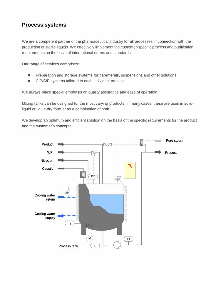
We are a competent partner of the pharmaceutical industry for all processes in connection with the
production of sterile liquids. We effectively implement the customer-specific process and purification
requirements on the basis of international norms and standards.
Our range of services comprises:
● Preparation and storage systems for parenterals, suspensions and other solutions
● CIP/SIP systems tailored to each individual process
We always place special emphasis on quality assurance and ease of operation.
Mixing tanks can be designed for the most varying products. In many cases, these are used in solid-
liquid or liquid-dry form or as a combination of both.
We develop an optimum and efficient solution on the basis of the specific requirements for the product
and the customer‘s concepts.
Process systems
Product
PIC
TI
Process tank
Caustic
WFI
PI
Nitrogen
Cooling water
return
Cooling water
supply
M
LI
Pure steam
Product
Product
PICPIC
TI
Process tank
Caustic
WFI
PI
Nitrogen
Cooling water
return
Cooling water
supply
M
LI
Pure steam
Product

Process systems
The following essential points have to be considered in the design of mixing tanks:
● Sanitary design
● Suitable mixing devices
● Cleaning or intermediate cleaning
● Product losses
● Dosing accuracy
● Traceability
● Batch separation
● Drainability
● Separation of different media
(double block and bleed)
● Sanitisability / sterilisability
As a rule, the project starts with the user requirement specification (URS). From this, the functional
specifications (flow diagram and functional description) are developed. The system is finally defined by
the subsequent design specification (DS).
We firmly believe that each production process should commence with cleaning, sterilisation or
sanitisation. Only a system that is free from residues and bioactive materials will allow safe and perfect
production. The CIP / SIP station must be designed accordingly.
Cleaning is carried out in three subsequent steps:
● Transport of the destabilising energy carrier to the contamination
(mechanically, thermally, chemically)
● Destabilisation by converting the contamination into a transportable condition by the chemical
and physical action of the cleaning agents
● Removal of the destabilised contamination from the surface
Reproducible system cleaning is deemed to be the
central quality criterion:
● The contact temperature and time of the
cleaning media used are constant during the
cleaning time.
● The batching of the cleaning agents is
reproducible.
● Any mixing of the cleaning media with the
operating media, raw materials or products
must be prevented.

Our specialists develop solutions for the different wastewaters that are produced during drug
production. The chemical-physical and biological processes employed are adapted specifically to the
individual circumstances and needs of our customers.
They are supported by our corporate laboratory and pilot plant facilities. Results from analyses and
pilot projects are evaluated directly and translated into enhanced products. Our scope of delivery
includes own processes (some patented) and standardised plant concepts for:
● Physico-chemical treatment by sedimentation or flotation
● Aerobic/anaerobic biological treatment in membrane bioreactors
or bio-aeration
● De-activation of active substances by UV oxidation together with ozone or hydrogen peroxide
● Sterilisation and decontamination of infectious and bioactive substances from biotechnology
Waste water treatment
The waste waters from drug production are treated by means of neutralisation and sludge
separation.
A biological stage with downstream MBR membrane unit treats the waste water in accordance with
discharge requirements. In many cases, the purity achieved allows the waste water to be reused for
secondary purposes.
An anaerobic stage provides the possibility to generate energy by utilising the biogas produced.
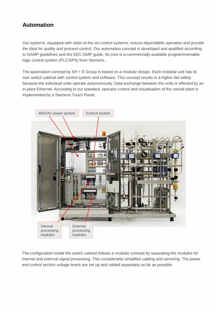
Our systems, equipped with state-of-the-art control systems, ensure dependable operation and provide
the data for quality and process control. Our automation concept is developed and qualified according
to GAMP guidelines and the EEC-GMP guide. Its core is a commercially available programmemable
logic control system (PLC/SPS) from Siemens.
The automation concept by SH + E Group is based on a modular design. Each modular unit has its
own switch cabinet with control system and software. This concept results in a higher fail-safety
because the individual units operate autonomously. Data exchange between the units is effected by an
in-plant Ethernet. According to our standard, operator control and visualisation of the overall plant is
implemented by a Siemens Touch Panel.
Automation
The configuration inside the switch cabinet follows a modular concept by separating the modules for
internal and external signal processing. This considerably simplifies cabling and servicing. The power
and control section voltage levels are set up and cabled separately as far as possible.
Internal
processing
modules
External
processing
modules
400VAC power section Control section

To ensure independent operation of the production and/or distribution system during maintenance
or repair, each switch cabinet is equipped with its own control system:
● Automatic operation
● Commercially available PLC
● Independent operation of individual units thanks to the modular design
● Use of validated software modules
● Controlled behaviour during a failure of operating media or limit value
exceed
● Easy and clear operator control through colour Touch Panel MP377, 15“
● Access authorisation concept through passwords with different
intervention levels
Automation
other stations
4 Potential free
contacts:
1x Common fault,
3 x Reserve
Switch cabinet
Generation
Power supply
400VAC/50Hz
Ethernet
4 Potential free
contacts:
1x Common fault,
3 x Reserve
Switch cabinet
Storage/
Distribution
Power supply
400VAC/ 50Hz
DrivesInstruments 4-20mA
Sensors 24VDC
Field instruments
Telephone line
analogue
ET200S
MP377 15”
CPU
IM151-8
PN/DP
Moros
Emergency Stop
installed on
Rack
ET200S
CPU
IM151-8
PN/DP
DrivesInstruments 4-20mA
Sensors 24VDC
Field instruments

We know we can rely on the modular units of Series S7/ ET200S. Sensor and actuator cables can be
connected directly to the units without intermediate terminal. This provides flexibility for upgrading and
considerably simplifies troubleshooting for servicing.
Automation
A colour operator control panel from Siemens is included to allow detection of the current operating
state of the system or intervention in the automatic sequence of the system.

To safeguard the automatic programme runs of the system, an individual Step 7 programme is
developed and transmitted to the PLC. This programme coordinates the switching of all actuators and
responds to the sensor signals and information read in. The automation concept is based on the
standard software and standard blocks from Siemens. For the development of systems and unit
software, SH + E Group created a comprehensive pool of standard blocks. These blocks were tested
and qualified together with the display driver blocks for the visualisation systems. A specification
document explaining and documenting the functioning, parameters and tests was prepared for each
block.
The part to be qualified is reduced through the use of these software standards because only the new
links between the standard blocks have to be qualified.
Automation
The Siemens standard software WinCC flexible forms the basis for operator control and visualisation.
Standardised software modules from SH + E Group are used for the system-specific application
software.
For planning of circuit diagrams and switch cabinets, SH + E Group relies on the EPLAN P8 planning
tool. This tool allows a modular design and qualification of the planning course by means of
standardised macro plans.

Automation
Access to the operator panel is protected by passwords at different levels.
For user identification, entering the ID and the password is required. Code word ageing can also be
activated. Four operator levels are provided for access protection:
Level 0: No password protection. Only information can be read
(display selection and fault indications)
Level 1: Plus operation of the system
Level 2: Plus parameter setting
Level 3: Plus password administration
All setting parameters of the system are deposited in a “formulation” as a security backup. After the
parameters have been altered, they can be stored by pressing a key and are available for a recovery
procedure if necessary.
The process values are displayed as trend curves. Reading of the values is supported by a reading
line.
Process values and messages are stored in internal data archives by WinCC flexible/ Archives. This
allows long-term documentation and evaluation of the process course. To determine whether the data
has been altered subsequently, the stored process data is given a checksum. Recorded and archived
data is cyclically swapped out to an external memory or monitoring system.
Automation
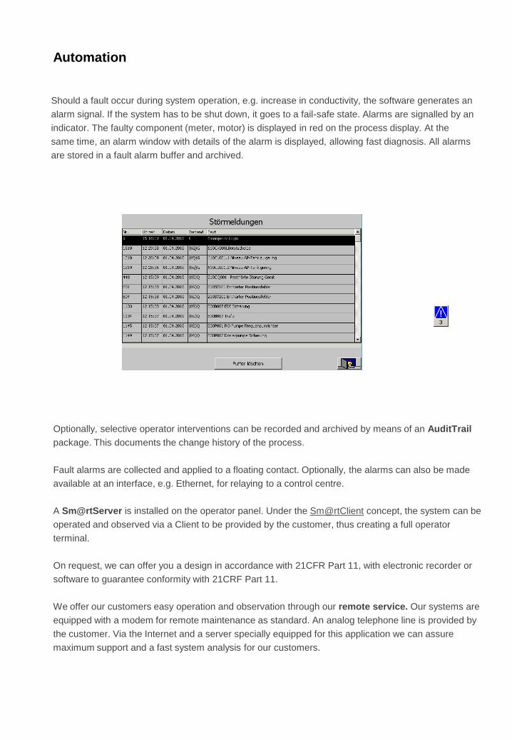
Should a fault occur during system operation, e.g. increase in conductivity, the software generates an
alarm signal. If the system has to be shut down, it goes to a fail-safe state. Alarms are signalled by an
indicator. The faulty component (meter, motor) is displayed in red on the process display. At the
same time, an alarm window with details of the alarm is displayed, allowing fast diagnosis. All alarms
are stored in a fault alarm buffer and archived.
Optionally, selective operator interventions can be recorded and archived by means of an AuditTrail
package. This documents the change history of the process.
Fault alarms are collected and applied to a floating contact. Optionally, the alarms can also be made
available at an interface, e.g. Ethernet, for relaying to a control centre.
A Sm@rtServer is installed on the operator panel. Under the Sm@rtClient concept, the system can be
operated and observed via a Client to be provided by the customer, thus creating a full operator
terminal.
On request, we can offer you a design in accordance with 21CFR Part 11, with electronic recorder or
software to guarantee conformity with 21CRF Part 11.
We offer our customers easy operation and observation through our remote service. Our systems are
equipped with a modem for remote maintenance as standard. An analog telephone line is provided by
the customer. Via the Internet and a server specially equipped for this application we can assure
maximum support and a fast system analysis for our customers.

Qualification and documentation
Hazard Analysis
DQ / Enhanced
Design Review
User
Requirements
Specification
(URS)
Functional
Specification (FS)
acc. to GAMP
Performance
Qualification
(PQ)
Operation
Qualification
(OQ)
Installation
Qualification
(IQ)
Implementation
Detailed
Planning Documents:
PID, List of
Components,
Circuit Diagram, etc.
SH + E Group has extensive experience with the qualification and documentation of systems in the
pharmaceutical industry. Standardised and tried-and-tested qualification documents such as protocols,
reports and SOPs are available for this purpose. The individual tests for the various qualification steps
DQ (on request), IQ, OQ are based on one another. The scope of testing is based on our hazard
analysis. The documents prepared by us comply with the specifications of FDA and the European
Commissions.
● Prepared protocols, reports and SOPs for DQ, IQ, OQ
● Optimally adapted to our systems
● The scope of testing is based on the SH + E Group hazard analysis
● Specially trained experts
● Design according to GMP and GAMP
● Own test bench for wet tests
● Option: Drawing up of the specification
and hazard analysis
Our qualification is based on the V-Model of the ISPE Guide or the definition
in GAMP:

The Installation Qualification (IQ) provides documented evidence that the system has been installed
in accordance with the planned requirements. At SH + E Group, the IQ is made up of three major steps:
● Material certificates to EN 10204 3.1
● FDA declaration of conformity for parts coming into contact with the product
● Factory calibration certificates for
quality-relevant instruments
● Welding documentation
● Receiving inspection documents
● Operating and maintenance manual
● Technical documentation for individual components
● Checking the completeness against P&I diagrams and list of components
● Inspection of filters and membrane elements
● Mechanical inspection (installation, accessibility, 3D rule,gradient as far as applicable) against
P&I diagrams and layout drawing
● Drainability
● Inspection of welds
● Optionally: Leakage test / hydraulic test (acc. to SOP)
● Flushing of the system acc. to cleaning record
● Identification / labelling
● Checking the switch cabinet against the electrical documentation acc. to SOP
● Electrical line test acc. to SOP
● Software registration
● Inspection of the visualisation
Qualification and documentation

The Operation Qualification (OQ) assures that all system components and systems are functioning
in conformity with the specification and reproducibly. The OQ covers the inspection of all operating
conditions (including Min., Max. conditions), all process parameters and sequences, as well as the
process safety.
At SH + E Group, the OQ comprises the following tests:
● Checking the utilities (raw water, compressed air,
regenerating salt, steam,...)
● Inspection of filters and
membrane elements
● Setting of the process parameters
● Checking the sanitisation
● Checking the sense of rotation of the motors
● Software test
● Password test
● Stress test
(power failure, compressed air failure,
restart behaviour)
● Performance test (water volume, conductivity, if necessary TOC and Ozone)
● Documentation of the operator training
● Optionally: Field calibration of critical instruments acc. to SOPs
The system is tested in the factory. Where possible, the system is subjected to a wet test on our test
stand before it leaves the factory. All functions and installations are tested in accordance with an
FAT test plan.
The Factory Acceptance Test (FAT) can be attended by the customer.
The documentation comprises the required documents according to our standard in German and in
the metric system. They are made up of the relevant shop drawings (P&I diagrams, layout
drawings), maintenance manual, EMSR (electrical, instrumentation & control) documentation, list of
components, spare parts list and test certificates.
Qualification and documentation
For trouble-free, safe and cost-effective operation of your system, professional support
by our trained staff is an absolute necessity.
Our convincing quality in terms of advice, implementation and service are an
indispensable prerequisite for long-term customer loyalty. Our service team is available
to you at any time for all inspection, servicing and maintenance tasks.
Our individual service packages are fully tailored to your needs, wishes and your time
schedule – at a fixed price. The fixed-price agreement contributes to cost transparency
for operation of your system.
We are at your service whenever you need us +49 (0) 711 78 66-261
Our regional service engineers are on call 24 hours a day and can be contacted via our
central Service Hotline. A dense support network with competent logistics support
assures rapid assistance.
In addition, the following further services are available to you:
Customer service tailored to your needs
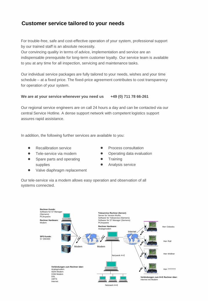
Our tele-service via a modem allows easy operation and observation of all
systems connected.
Herr Oskedra
Herr Rall
Teleservice Rechner (Server):
Server für Version Works
Software für Teleservice (Siemens)
Software für S7 Manager (Siemens)
PCAnywere
Rechner Hardware:
Analogmodem
Verbindungen zum Rechner über:
Analogmodem
ISDN Modem
GSM Modem
DSL
UMTS
Internet
Verbindungen zum H+E Rechner über:
Internet mit Modem
Netzwerk H+E
Herr Wöllner
Herr ???????
Rechner Kunde:
Software für S7 Manager
(Siemens)
PCAnywere
Rechner Hardware:
Modem
Internet
ModemModem
SPS Kunde:
S7 300/400
Netzwerk H+E
● Recalibration service
● Tele-service via modem
● Spare parts and operating
supplies
● Valve diaphragm replacement
● Process consultation
● Operating data evaluation
● Training
● Analysis service

Your information is of great importance to us, since only detailed information will
enable us to draw up a tailor-made offer for you. This questionnaire is intended to
assist you in describing your requirements (please tick or enter as appropriate):
О Town water
О Well water
О Surface water (e.g. cistern, river or lake)
О Other ............................................
________________________________________
О Raw water analysis attached
О Raw water data as follows
Electr. conductivity ………..µS/cm
pH ……….
Temperature ………. °C
TOC ………. ppm
Bacteria count ………. CFU/ml
Total hardness ………. °dH / ppm CaCO3
Alkalinity ………. ppm CaCO3
Iron ………. ppm
Manganese ………. ppm
Silica (SiO2) ………. ppm
Chlorine, ozone, etc. ………. ppm
SDI (15 min) ……….
________________________________________
О Yes
О No
________________________________________
Which plant systems are to be installed?
Your requirements
Raw water source
Raw water analysis
Seasonal
fluctuations
Scope of delivery
Technical questionnaire – Purified utility systems – Page 1/4
PW / HPW system
О Production
О Storage
О Distribution
О Loop
О Other……………
WFI system
О Production
О Storage
О Distribution
О Loop
О Other……………
HP steam system
О Production
О HP steam piping
О Other……………

Which pharmacopoeias are to be complied with?
О EP (currently valid version)
О USP (currently valid version)
О Highly Purified Water acc. to EP
О Other ................................................
Other spec. requirements Electr. conductivity ………. µS/cm
TOC ………. ppm
Bacterial count ………. KBE/ml
Endotoxins ………. EU/ml
Other ………………………
………………………
________________________________________
Which sanitisation method is to be used for the PW system?
PW / HPW production
О Thermal, with hot water (> 80°C)
О Thermal, with hot water + hot brine
О Cold, with chemicals
PW storage and distribution system
О Cold storage with ozone/UV sterilisation
О Cold storage with UV and periodic hot water sanitisation (80 °C)
О Hot storage and distribution (80 °C)
HPW / WFI storage and distribution system
О Cold storage with ozone/UV sterilisation
О Hot storage and distribution (80 °C)
________________________________________
Production runs not more than
……. shifts a day …… hours per shift
The PW consumption at the point of use is:
О acc. to attached list of consumers
Total consumption …… m³/day
Short-term peak load …… m³/h
Requirements for
pharma water
Sanitisation
Capacities of
PW system
Technical questionnaire – Purified utility systems – Page 2/4
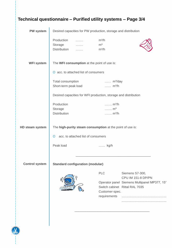
Desired capacities for PW production, storage and distribution
Production ……. m³/h
Storage ……. m³
Distribution ……. m³/h
The WFI consumption at the point of use is:
О acc. to attached list of consumers
Total consumption …… m³/day
Short-term peak load …… m³/h
Desired capacities for WFI production, storage and distribution
Production ……. m³/h
Storage ……. m³
Distribution ……. m³/h
The high-purity steam consumption at the point of use is:
О acc. to attached list of consumers
Peak load …… kg/h
________________________________________
Standard configuration (modular)
PLC Siemens S7-300,
CPU IM 151-8 DP/PN
Operator panel Siemens Multipanel MP377, 15“
Switch cabinet Rittal RAL 7035
Customer-spec.
requirements ...................................................
...................................................
________________________________________
PW system
WFI system
HD steam system
Control system
Technical questionnaire – Purified utility systems – Page 3/4

In accordance with INCOTERMS 2010
О EXW
О FOB …………………………….
О CIP …………………………….
О DAP …………………………….
О Other …………………………….
________________________________________
Our requirements for utilities and ambient conditions
Ambient conditions
Room temperature min. 5 °C / max. 35 °C
Humidity max. 60%
Utilities
Power 3 x 400V / 50 Hz, +/- 10%
Compressed air oil-free, min. 6 bar
Saturated steam min. 6 bar
Cooling water max. 12 °C (4 bar)
________________________________________
............................................................................................................
............................................................................................................
............................................................................................................
............................................................................................................
............................................................................................................
............................................................................................................
............................................................................................................
________________________________________
Company ......................................................................
address ......................................................................
......................................................................
Contact ......................................................................
Tel. No. ......................................................................
Fax No. ......................................................................
E-mail ......................................................................
________________________________________
Please return to FAX +49 711 78 66 - 316
Terms of delivery
General
requirements
Further
information
Address
Answer by FAX
Technical questionnaire – Purified utility systems – Page 4/4

SH+E Group ranks among the world's leading
suppliers in the fields of water, energy and
process engineering. Based on its global
presence, the SH+E GROUP has executed
projects in more than 160 countries.
Tel. +49 7748 9200-777
www.she-group.com


