28
USER’S MANUAL Turbo INLINE MIXED-FLOW FANS EN
USER’S MANUAL
Turbo
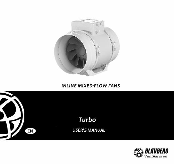
INLINE MIXED-FLOW FANS
EN

2
EN
CONTENTSDelivery set ................................................................................................................................................................................................................6Brief description .....................................................................................................................................................................................................6Operation guidelines ..........................................................................................................................................................................................7Designation key ....................................................................................................................................................................................................8Installation .................................................................................................................................................................................................................9Electronics operation algorithm ..................................................................................................................................................................10Technical maintenance ......................................................................................................................................................................................12Storage and transportation regulations ..................................................................................................................................................12Manufacturer’s warranty ...................................................................................................................................................................................13
This user’s manual is a main operating document intended for technical, maintenance, and operating staff.The manual contains information about purpose, technical details, operating principle, design, and installation of the Turbo unit and all its modifications.Technical and maintenance staff must have theoretical and practical training in the field of ventilation systems and should be able to work in accordance with workplace safety rules as well as construction norms and standards applicable in the territory of the country.The information in this user’s manual is correct at the time of the document’s preparation.The Company reserves the right to modify the technical characteristics, design, or configuration of its products at any time in order to incorporate the latest technological developments.No part of this publication may be reproduced, stored in a retrieval system, or transmitted, in any form or by any means in any information search system or translated into any language in any form without the prior written permission of the Company.
3
EN
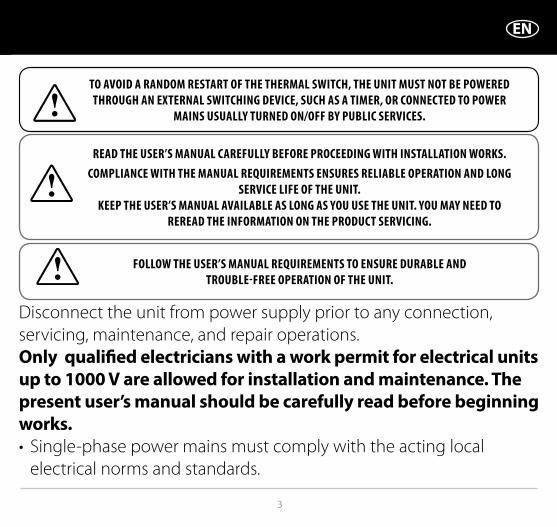
READ THE USER’S MANUAL CAREFULLY BEFORE PROCEEDING WITH INSTALLATION WORKS.COMPLIANCE WITH THE MANUAL REQUIREMENTS ENSURES RELIABLE OPERATION AND LONG
SERVICE LIFE OF THE UNIT.KEEP THE USER’S MANUAL AVAILABLE AS LONG AS YOU USE THE UNIT. YOU MAY NEED TO
REREAD THE INFORMATION ON THE PRODUCT SERVICING.
TO AVOID A RANDOM RESTART OF THE THERMAL SWITCH, THE UNIT MUST NOT BE POWERED THROUGH AN EXTERNAL SWITCHING DEVICE, SUCH AS A TIMER, OR CONNECTED TO POWER
MAINS USUALLY TURNED ON/OFF BY PUBLIC SERVICES.
FOLLOW THE USER’S MANUAL REQUIREMENTS TO ENSURE DURABLE AND TROUBLE-FREE OPERATION OF THE UNIT.
Disconnect the unit from power supply prior to any connection, servicing, maintenance, and repair operations. Only qualified electricians with a work permit for electrical units up to 1000 V are allowed for installation and maintenance. The present user’s manual should be carefully read before beginning works.• Single-phase power mains must comply with the acting local
electrical norms and standards.
4
EN
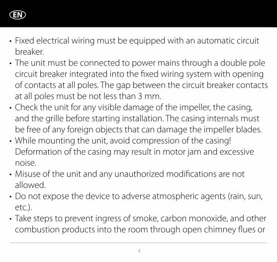
• Fixed electrical wiring must be equipped with an automatic circuit breaker.
• The unit must be connected to power mains through a double pole circuit breaker integrated into the fixed wiring system with opening of contacts at all poles. The gap between the circuit breaker contacts at all poles must be not less than 3 mm.
• Check the unit for any visible damage of the impeller, the casing, and the grille before starting installation. The casing internals must be free of any foreign objects that can damage the impeller blades.
• While mounting the unit, avoid compression of the casing! Deformation of the casing may result in motor jam and excessive noise.
• Misuse of the unit and any unauthorized modifications are not allowed.
• Do not expose the device to adverse atmospheric agents (rain, sun, etc.).
• Take steps to prevent ingress of smoke, carbon monoxide, and other combustion products into the room through open chimney flues or

5
EN
other fire-protection devices. Sufficient air supply must be provided for proper combustion and exhaust of gases through the chimney of fuel burning equipment to prevent back drafting.
• Transported air must not contain any dust or other solid impurities, sticky substances, or fibrous materials.
• Do not use the unit in a hazardous or explosive environment containing spirits, gasoline, insecticides, etc.
• For effective functioning of the unit, it is necessary to ensure an appropriate fresh air supply into the room. Do not close or block the intake or extract vents in order to ensure the efficient air flow.
• Do not sit on the unit and do not put objects on it.• The unit is allowed to be used by children aged from 8 years old
and above and persons with reduced physical, sensory, or mental capabilities or no experience and knowledge provided that they have been given supervision or instruction regarding safe use of the unit and understand the risks involved.
• Do not allow children to play with the unit. • The information in this user’s manual was correct at the time of the

6
EN
document’s preparation. • The Company reserves the right to modify the technical
characteristics, design, or configuration of its products at any time in order to incorporate the latest technological developments.
• No part of this publication may be reproduced, stored in a retrieval system, or transmitted, in any form or by any means in any information search system or translated into any language in any form without the prior written permission of the Company.
WARNING! Similar to the use of any other household electrical appliances when operating this fan, the following basic rules must be followed:• Never touch the fan with wet or damp hands.• Never touch the fan when barefoot.
THE PRODUCT MUST BE DISPOSED SEPARATELY AT THE END OF ITS SERVICE LIFE.DO NOT DISPOSE THE UNIT AS UNSORTED DOMESTIC WASTE.

7
EN
DELIVERY SETFan — 1 pc.Screws and dowels — 4 pcs.Plastic screwdriver (for models with a timer) — 1 pc.User’s manual — 1 pc.Packing box — 1 pc.
BRIEF DESCRIPTIONThe product described herein is a mixed-flow inline fan for supply or extract ventilation of premises.The fan is designed for connection to ø 100, 125, 150, 160, 200, 250 and 315 mm air ducts.The unit is equipped with a two speed motor.
Ø D B H L
Turbo 100 97 195,8 226/255* 302,5
Turbo 125 123 195,6 226/255* 258,5
Turbo 150 148 220,1 247/265* 289
Turbo 160 158 220,1 247/265* 289
Turbo 200 199 239 261/278* 295,5
Turbo 250 247 287 323/340* 383
Turbo 315 310 362 408/424* 445
* Turbo XXX GI1/G1/GTI1/GT1/GSI1/GS1/FR1
8
EN
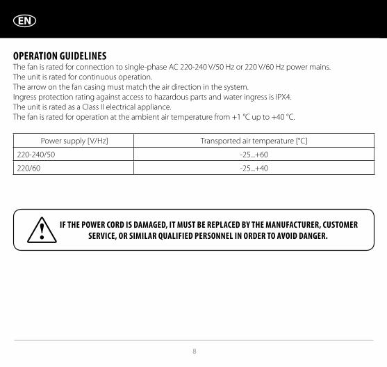
OPERATION GUIDELINESThe fan is rated for connection to single-phase AC 220-240 V/50 Hz or 220 V/60 Hz power mains.The unit is rated for continuous operation.The arrow on the fan casing must match the air direction in the system.Ingress protection rating against access to hazardous parts and water ingress is IPX4.The unit is rated as a Class II electrical appliance.The fan is rated for operation at the ambient air temperature from +1 °C up to +40 °C.
Power supply [V/Hz] Transported air temperature [°C]
220-240/50 -25...+60
220/60 -25...+40
IF THE POWER CORD IS DAMAGED, IT MUST BE REPLACED BY THE MANUFACTURER, CUSTOMER SERVICE, OR SIMILAR QUALIFIED PERSONNEL IN ORDER TO AVOID DANGER.

9
EN
DESIGNATION KEY Turbo XXX X
Options:T: timer US: speed switchGl1: speed controller with an electronic thermostat and a temperature sensor integrated inside an air duct. Temperature-based operation logicG1: speed controller with an electronic thermostat and an outdoor temperature sensor fixed on a 4 m cable. Temperature-based operation logicGTl1: speed controller with an electronic thermostat and an integrated temperature sensor. Timer-based operation logicGT1: speed controller with an electronic thermostat and an outdoor temperature sensor fixed on a 4 m cable. Timer-based operation logicGSl1: speed controller with an electronic thermostat and an integrated temperature sensor. Temperature-based switching on/offGS1: speed controller with an electronic thermostat and an outdoor temperature sensor fixed on a 4 m cable. Temperature-based switching on/off.FR1: integrated smooth speed controllerSpigot diameter [mm]Inline mixed-flow fan

10
EN
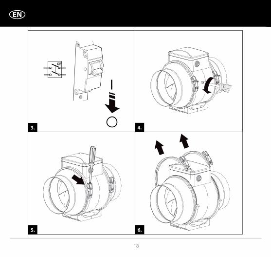
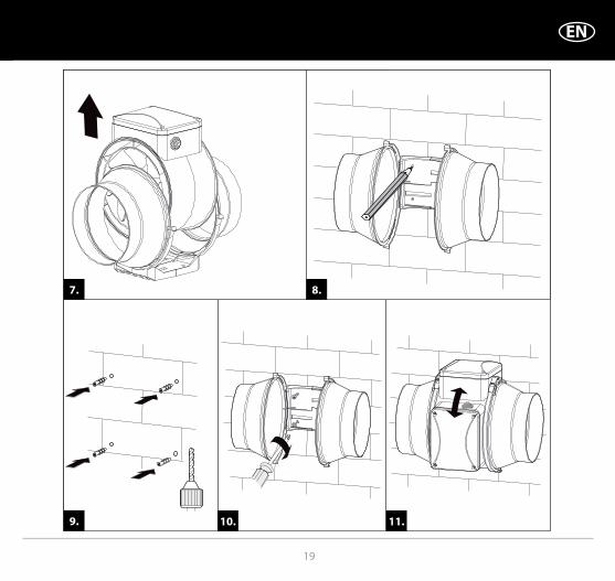
MOUNTING The fan is suitable both for horizontal or vertical mounting on the floor, on the wall or on the ceiling (Fig. 1). The fan can be installed independently or as part of a set with parallel or in-series connection (Fig. 2).Install minimum 1 m long air duct on the intake spigot side in case of horizontal fan mounting or a hood in case of vertical fan mounting.The outlet spigot must always be connected to the air duct. The fan mounting sequence is shown in Fig. 3-11 and 14-19. The fan wiring diagrams are shown in Fig. 12-13. Some fan models are equipped with a plastic limit stop in front of the L1 terminal. Remove the limit stop for connection to the L1 terminal. Designation:L1 – minimum speed terminalL2 – maximum speed terminalQF – automatic circuit breakerS – external speed controllerST – external switch (for example, a light switch)X – input terminal
QF
S S/ST
Automatic circuit breaker designation
Automatic circuit breaker
External switch designation External switch

11
EN
CONTROL LOGICThe Turbo XXX T fan starts running after the external switch supplies control signal to the LT input terminal (for example, during turning the light on). After removal of the control signal the fan continues to run within the set time (adjustable with the turn-off delay timer from 2 to 30 minutes).To adjust the fan turn-off delay time, rotate the control knob T clockwise to increase and counter-clockwise to decrease the turn-off delay time respectively (Fig. 20).
Warning! The timer circuit is under mains voltage. Disconnect the fan from power supply prior to any adjustment operations. The fan delivery set includes a specially designed plastic screwdriver for adjustment of the fan parameters. Use exclusively the delivered plastic screwdriver to adjust the turn-off delay time. Do not use a metal screwdriver, knife, etc. for adjustment operations not to damage the circuit board.
The Turbo Gl1/GTl1/GSl1/GS1 fan is equipped with an electronic TSC control unit (speed controller with electronic thermostat) for automatic speed control (air flow control) depending on the air temperature (Fig. 22).
The terminal box cover incorporates 2 control knobs:• for setting the fan speed;• for setting the thermostat set point.The thermostat LED light is located on the fan casing.The thermostat LED glows as air temperature exceeds the set point.To set the thermostat set point rotate the temperature control knob clockwise to increase or counter-clockwise to decrease the temperature set point accordingly.To set the fan speed (air flow) rotate the speed control knob in the same way.

12
EN
The fan functioning logic may be based on temperature or timer controls:Turbo ХХХ Gl1/G1: the fan switches to the maximum speed as the room air temperature exceeds the set point. As the air temperature drops down 2 °C below the temperature set point or if the initial temperature is below the set point, the fan operates with the set speed.Turbo ХХХ GTl1/GT1: the fan switches to the maximum speed as the room air temperature exceeds the set point.As the room air temperature drops down below the temperature set point, the timer starts 5 minutes countdown and then the fan switches to the set speed.Turbo ХХХ GSl1/GS1:As the indoor air temperature exceeds the set point, the fan switches to the maximum speed. As the air temperature drops 2 °C below the set point or if the initial temperature is below the set point, the fan is turned off.
The Turbo XXX FR1 fan is equipped with a speed controller that enables switching the fan on/off, smooth speed (air flow) control from minimum to maximum value (Fig. 22).

13
EN
TECHNICAL MAINTENANCEThe fan surfaces must be regularly cleaned (once in 6 months) from dirt and dust (Fig. 24-30). Disconnect the fan from power mains prior to any maintenance operations. To clean the fan, use a soft cloth or a brush wetted in a mild detergent solution. Do not allow water or liquid come into contact with electric components (Fig. 30). Wipe the surfaces dry after cleaning.
14
EN
STORAGE AND TRANSPORTATION REGULATIONS• Store the unit in the manufacturer’s original packaging box in a dry closed ventilated premise with
temperature range +5...+40 ˚С and relative humidity up to 70 %.• Storage environment must not contain aggressive vapors and chemical mixtures provoking corrosion,
insulation, and sealing deformation.• Use suitable hoist machinery for handling and storage operations to prevent possible damage to the unit.• Follow the handling requirements applicable for the particular type of cargo.• The unit can be carried in the original packaging by any mode of transport provided proper protection
against precipitation and mechanical damage. The unit must be transported only in the working position.• Avoid sharp blows, scratches, or rough handling during loading and unloading.• Prior to the initial power-up after transportation at low temperatures, allow the unit to warm up at operating
temperature for at least 3-4 hours.

15
EN
MANUFACTURER’S WARRANTYThe product is in compliance with EU norms and standards on low voltage guidelines and electromagnetic compatibility. We hereby declare that the product complies with the provisions of Electromagnetic Compatibility (EMC) Directive 2014/30/EU of the European Parliament and of the Council, Low Voltage Directive (LVD) 2014/35/EU of the European Parliament and of the Council and CE-marking Council Directive 93/68/EEC. This certificate is issued following test carried out on samples of the product referred to above.The manufacturer hereby warrants normal operation of the unit for 24 months after the retail sale date provided the user's observance of the transportation, storage, installation, and operation regulations. Should any malfunctions occur in the course of the unit operation through the Manufacturer's fault during the guaranteed period of operation, the user is entitled to get all the faults eliminated by the manufacturer by means of warranty repair at the factory free of charge. The warranty repair includes work specific to elimination of faults in the unit operation to ensure its intended use by the user within the guaranteed period of operation. The faults are eliminated by means of replacement or repair of the unit components or a specific part of such unit component.
The warranty repair does not include: • routine technical maintenance• unit installation/dismantling • unit setupTo benefit from warranty repair, the user must provide the unit, the user's manual with the purchase date stamp, and the payment paperwork certifying the purchase. The unit model must comply with the one stated in the user’s manual. Contact the Seller for warranty service.
The manufacturer’s warranty does not apply to the following cases:• User’s failure to submit the unit with the entire delivery package as stated in the user’s manual including
submission with missing component parts previously dismounted by the user.• Mismatch of the unit model and the brand name with the information stated on the unit packaging and
in the user's manual.

16
EN
• User’s failure to ensure timely technical maintenance of the unit.• External damage to the unit casing (excluding external modifications as required for installation) and
internal components caused by the user.• Redesign or engineering changes to the unit.• Replacement and use of any assemblies, parts and components not approved by the manufacturer.• Unit misuse.• Violation of the unit installation regulations by the user.• Violation of the unit control regulations by the user.• Unit connection to power mains with a voltage different from the one stated in the user's manual.• Unit breakdown due to voltage surges in power mains.• Discretionary repair of the unit by the user.• Unit repair by any persons without the manufacturer’s authorization.• Expiration of the unit warranty period.• Violation of the unit transportation regulations by the user.• Violation of the unit storage regulations by the user.• Wrongful actions against the unit committed by third parties.• Unit breakdown due to circumstances of insuperable force (fire, flood, earthquake, war, hostilities of any
kind, blockades).• Missing seals if provided by the user’s manual.• Failure to submit the user’s manual with the unit purchase date stamp.• Missing payment paperwork certifying the unit purchase.
FOLLOWING THE REGULATIONS STIPULATED HEREIN WILL ENSURE A LONG AND TROUBLE-FREE OPERATION OF THE UNIT.
USER’S WARRANTY CLAIMS SHALL BE SUBJECT TO REVIEW ONLY UPON PRESENTATION OF THE UNIT, THE PAYMENT DOCUMENT AND THE USER’S MANUAL WITH THE PURCHASE DATE STAMP.

17
EN
min 1 m
1.
2.
18
EN
QF
3. 4.
5. 6.
19
EN
7. 8.
9. 10. 11.

20
EN
MAX
MIN
MAX / MIN
N
L2
N
LQF
~
QF
N
L1
L2
S
N
L
~M
N
L1
N
LQF
~ M
M
L2
L1
N
L~ M
12.
Turbo XXX

21
EN
MAX
MAX / MIN
MAX
MIN MIN
MAX / MIN
L2
L1
N
L~
X
N
LST
QF N
L
LT
L1
~
X
S
N
LST
QF N
L
LT
L1
~
X
L2
N
LST
QF N
L
LT
~
X
N
LST
QF N
L
LT
L1
~
X
S
N
LST
QF N
L
LT
L1
~
X
N
LST
QF N
L
LT
L2
~
X
13.
TERMINAL BLOCK FOR 5 CONTACTS TERMINAL BLOCK FOR 4 CONTACTS
Turbo XXX T

22
EN
25
QF
14. 15. 16.
17. 18. 19.

23
EN
- +
3030 min2 min
MIN
MAX
STOP
20.
21.

24
EN
33
����� ������������������
min max
~~~
22.
23.
Thermostat
control knob
Speed
control knob
Speed
control knob
Turbo Gl1/GTl1/GSl1
Turbo FR1
Turbo G1/GT1/GS1

25
EN
24. 25.
26. 27.

26
EN
18
28. 29.
30.
27
EN
Quality Inspector’s Stamp
Manufacture Date
Sold by(name and stamp of the seller)
Purchase Date
B77EN-04www.blaubergventilatoren.de
Turbo
100 T l 1
125 US
150 FR1
160 G
250
315


