1. All Interested Members of Civil Engineering Division Council, CEDC 2. All Members of CED 54 3. All others interested
Dear Sir (s),
Please find enclosed the following draft: Doc. No. Title
CED 54 (7589) Draft Indian Standard for Reinforcement Couplers for Mechanical Splices of Bars for Concrete Reinforcement – Specification (ICS No. 77.140.15) Kindly examine the draft standard and forward your views stating any difficulties which you are likely to experience in your business or profession, if this is finally adopted as National Standard. Last Date for comments: 20 05 2010
Comments if any may please be made in the format as given overleaf and mailed to the undersigned at the above address.
In case no comments are received or comments received are of editorial nature, you will kindly permit us to presume your approval for the above document as finalized. However, in case of comments of technical in nature are received then it may be finalized either in consultation with the Chairman, Sectional Committee or referred to the Sectional Committee for further necessary action if so desired by the Chairman, Sectional Committee.
The document is also hosted on BIS website www.bis.org.in.
Thanking you, Yours faithfully,
(A.K. Saini)
Sc ‘F’ & Head (Civil Engg.) Encl: as above e-mail: [email protected]
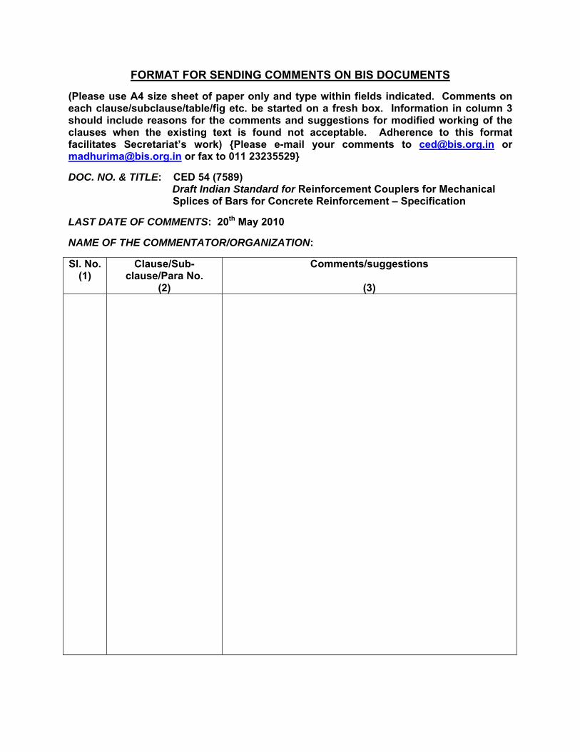
FORMAT FOR SENDING COMMENTS ON BIS DOCUMENTS
(Please use A4 size sheet of paper only and type within fields indicated. Comments on each clause/subclause/table/fig etc. be started on a fresh box. Information in column 3 should include reasons for the comments and suggestions for modified working of the clauses when the existing text is found not acceptable. Adherence to this format facilitates Secretariat’s work) {Please e-mail your comments to [email protected] or [email protected] or fax to 011 23235529}
DOC. NO. & TITLE: CED 54 (7589)
Draft Indian Standard for Reinforcement Couplers for Mechanical Splices of Bars for Concrete Reinforcement – Specification LAST DATE OF COMMENTS: 20th May 2010 NAME OF THE COMMENTATOR/ORGANIZATION: Sl. No.
(1) Clause/Sub-
clause/Para No. (2)
Comments/suggestions
(3)
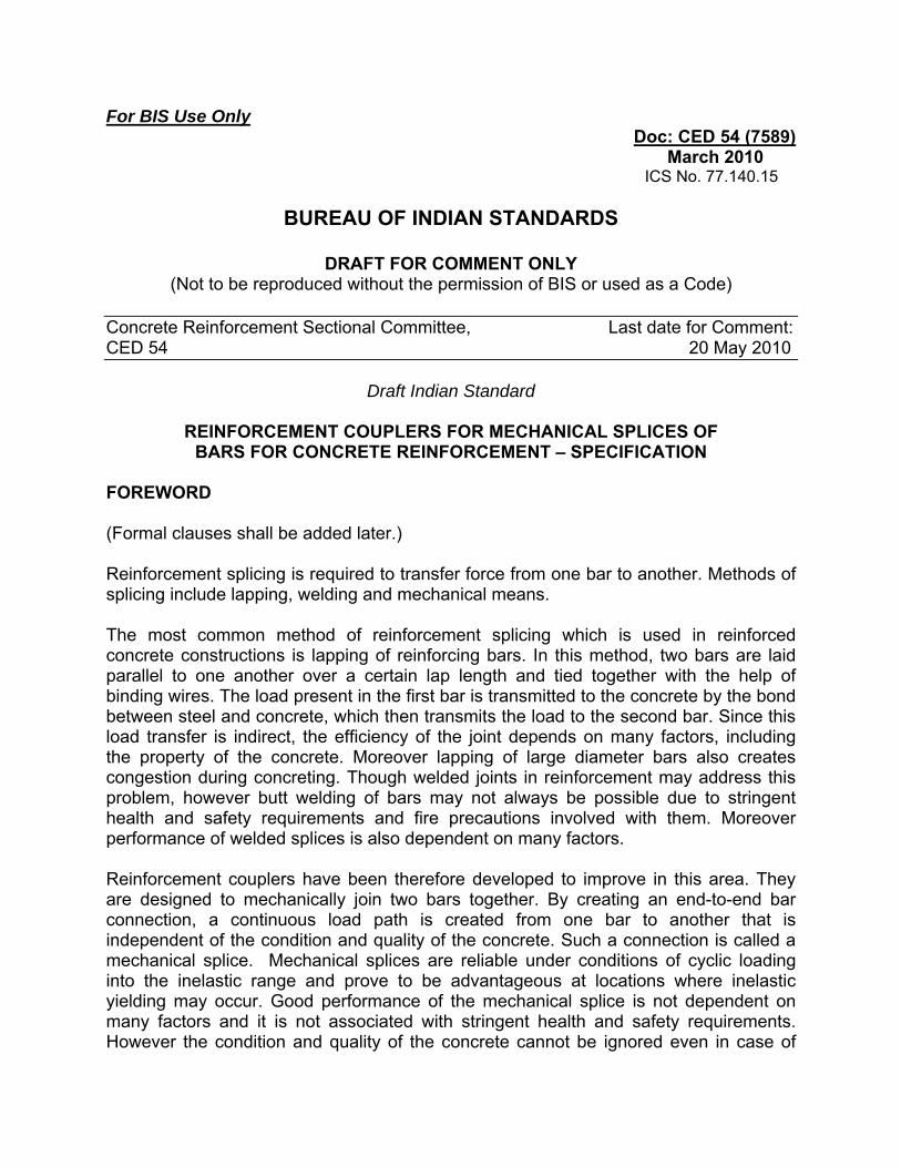
For BIS Use Only Doc: CED 54 (7589)
March 2010 ICS No. 77.140.15
BUREAU OF INDIAN STANDARDS
DRAFT FOR COMMENT ONLY
(Not to be reproduced without the permission of BIS or used as a Code)
Concrete Reinforcement Sectional Committee, Last date for Comment: CED 54 20 May 2010
Draft Indian Standard
REINFORCEMENT COUPLERS FOR MECHANICAL SPLICES OF BARS FOR CONCRETE REINFORCEMENT – SPECIFICATION
FOREWORD (Formal clauses shall be added later.) Reinforcement splicing is required to transfer force from one bar to another. Methods of splicing include lapping, welding and mechanical means. The most common method of reinforcement splicing which is used in reinforced concrete constructions is lapping of reinforcing bars. In this method, two bars are laid parallel to one another over a certain lap length and tied together with the help of binding wires. The load present in the first bar is transmitted to the concrete by the bond between steel and concrete, which then transmits the load to the second bar. Since this load transfer is indirect, the efficiency of the joint depends on many factors, including the property of the concrete. Moreover lapping of large diameter bars also creates congestion during concreting. Though welded joints in reinforcement may address this problem, however butt welding of bars may not always be possible due to stringent health and safety requirements and fire precautions involved with them. Moreover performance of welded splices is also dependent on many factors. Reinforcement couplers have been therefore developed to improve in this area. They are designed to mechanically join two bars together. By creating an end-to-end bar connection, a continuous load path is created from one bar to another that is independent of the condition and quality of the concrete. Such a connection is called a mechanical splice. Mechanical splices are reliable under conditions of cyclic loading into the inelastic range and prove to be advantageous at locations where inelastic yielding may occur. Good performance of the mechanical splice is not dependent on many factors and it is not associated with stringent health and safety requirements. However the condition and quality of the concrete cannot be ignored even in case of
mechanical splicing of bars and minimum clear cover requirement shall also be ensured. Due to the ease in application offered by mechanical splicing system for joining reinforcing bars, its popularity and use in the field of construction by many organizations in the country is increasing. A need was, therefore, felt to formulate an Indian Standard on the subject to specify various requirements for reinforcement couplers used for mechanical splicing of bars in concrete reinforcement. Being a new product for Indian construction industry, the Committee responsible for the formulation of this draft Indian standard decided to give information regarding most commonly used reinforcement couplers in the country, which is given at Annex A. The reinforcement couplers covered in this standard are meant to be used with reinforcing bars conforming to IS 1786:2008 ‘High strength deformed steel bars and wires for concrete reinforcement (fourth revision)’ and grades less than and equal to Fe 550 D. In view of limited production of Fe 600 grade reinforcing bar, requirement of couplers to be used with them have not been presently covered in this standard. The same may be mutually agreed by the purchaser and the manufacturer as per specific project necessities. Users may note that certain limitations are also associated with different types of reinforcement couplers. Some of them have been indicated in Annex A where information about different types of couplers has been given. Users are encouraged to follow minimum precautionary installation measures while using couplers in field. Users are also encouraged to carry out corrosion test in the coupler-bar connections exposed to marine or severe environmental conditions to rule out any risk of galvanic corrosion. Specialist literature may be referred to in such cases. Splicing of bars shall be done in accordance with the relevant requirements specified in IS 456:2000 ‘Plain and reinforced concrete— Code of practice (fourth revision)’. The provisions related to bending and fixing of bars for concrete reinforcement has been covered in IS 2502:1963 ‘Code of practice for bending and fixing of bars for concrete reinforcement’. In the formulation of this standard due weightage has been given to international co-ordination among the standards and practices prevailing in different countries in addition to relating it to the practices in the field in this country. Assistance has been derived from the following International Standards in the formulation of this standard: ISO 15835-1:2009 Steels for the reinforcement of concrete— Reinforcement
couplers for mechanical splices of bars— Part 1: Requirements
ISO 15835-2:2009 Steels for the reinforcement of concrete— Reinforcement couplers for mechanical splices of bars— Part 1: Test methods
However, variations have been made in the draft standard from the above International Standards in view of following reasons:
a) Requirements have been modified to align usage of couplers with reinforcing
bars conforming to IS 1786:2008 ‘High strength deformed steel bars and wires for concrete reinforcement— Specification’ which is not identical to International Standard of reinforcing bar, ISO 6935-2:2007 ‘Steel for the reinforcement of concrete-Part 2: Ribbed bars’. Requirements specified in IS 1786 are again linked to design principles specified in IS 456:2000 ‘Plain and reinforced concrete— Code of practice (fourth revision)’;
b) Variety reduction like reduction in number of grades and category on the basis of seismic requirements has been done to facilitate implementation of the standard and to avoid difficulty in stacking/grouping of couplers in construction site;
c) Performance requirements like tensile strength and percentage elongation at maximum force have been arrived at on the basis of the properties achieved in reinforcing bars manufactured in the country;
d) Keeping in view the earthquake zonation of India and testing facilities available in the country, changes have been made in requirement of low cycle fatigue test. Moreover additional 100 cycle test has been introduced. As entire country is earthquake prone, it has been specified in the draft standard that all couplers shall meet the low cycle fatigue test requirements. However similar provisions are not contained in ISO 15835-1:2009;
e) Standard temperature conditions prevailing in the country have been adopted for testing couplers; and
f) Variation has been made in sampling plan. Based on the consignment size generally offered in the country and keeping in view that all performance tests are destructive in nature the sampling plan and criteria for conformity has been prepared in accordance with IS 2500 (Part 1):2000/ISO 2589-1:1999 ‘Sampling procedure for inspection by attributes: Part 1 Sampling schemes indexed by acceptance quality limit (AQL) for lot-by-lot inspection (third revision)’.
For the purpose of deciding whether a particular requirement of this standard is complied with, the final value, observed or calculated, expressing the result of a test or analysis shall be rounded off in accordance with IS 2:1960 ‘Rules for rounding off numerical values (revised).’
For BIS Use Only Doc: CED 54 (7589)
March 2010 ICS No. 77.140.15
BUREAU OF INDIAN STANDARDS
DRAFT FOR COMMENT ONLY
(Not to be reproduced without the permission of BIS or used as a Code)
Concrete Reinforcement Sectional Committee, Last date for Comment: CED 54 15 May 2010
Draft Indian Standard
REINFORCEMENT COUPLERS FOR MECHANICAL SPLICES OF BARS FOR CONCRETE REINFORCEMENT – SPECIFICATION
1 SCOPE
1.1 This Indian standard covers the requirements and tests applicable to reinforcement couplers to be used for mechanical splicing of bars conforming to IS 1786 in reinforced concrete constructions. The standard presently covers requirements of couplers to be used with bars conforming to grades less than and equal to Fe 550 D of IS 1786. NOTE— The performance requirements for couplers to be used with reinforcing bars conforming to grade Fe 600 of IS 1786 shall be mutually agreed by the purchaser and the manufacturer as per specific project necessities. 1.2 The provisions of this standard applies to tension-only couplers such as threaded couplers, swaged coupling sleeves, grout/steel filled coupling sleeve etc, subject to satisfying the performance criteria of this standard. 1.3 This standard does not cover compression-only couplers such as end bearing sleeves and coupling sleeve and wedge. 2 REFERENCES The standards listed below contain provisions which, through reference in this text, constitute provision of this standard. At the time of publication, the editions indicated were valid. All standards are subject to revision, and parties to agreements based on this standard are encouraged to investigate the possibility of applying the most recent editions of the standards indicated below:
IS No. Title 1608:2005 Metallic materials — Tensile testing at ambient temperature (Third Revision) 1786:2008 High strength deformed steel bars and wires for concrete reinforcement — Specification (Fourth Revision) 1828 (Part 1):2005 Metallic materials - Verification of static uniaxial testing Machines: Part 1 Tension/Compression testing machines
— Verification and calibration of the force-measuring System
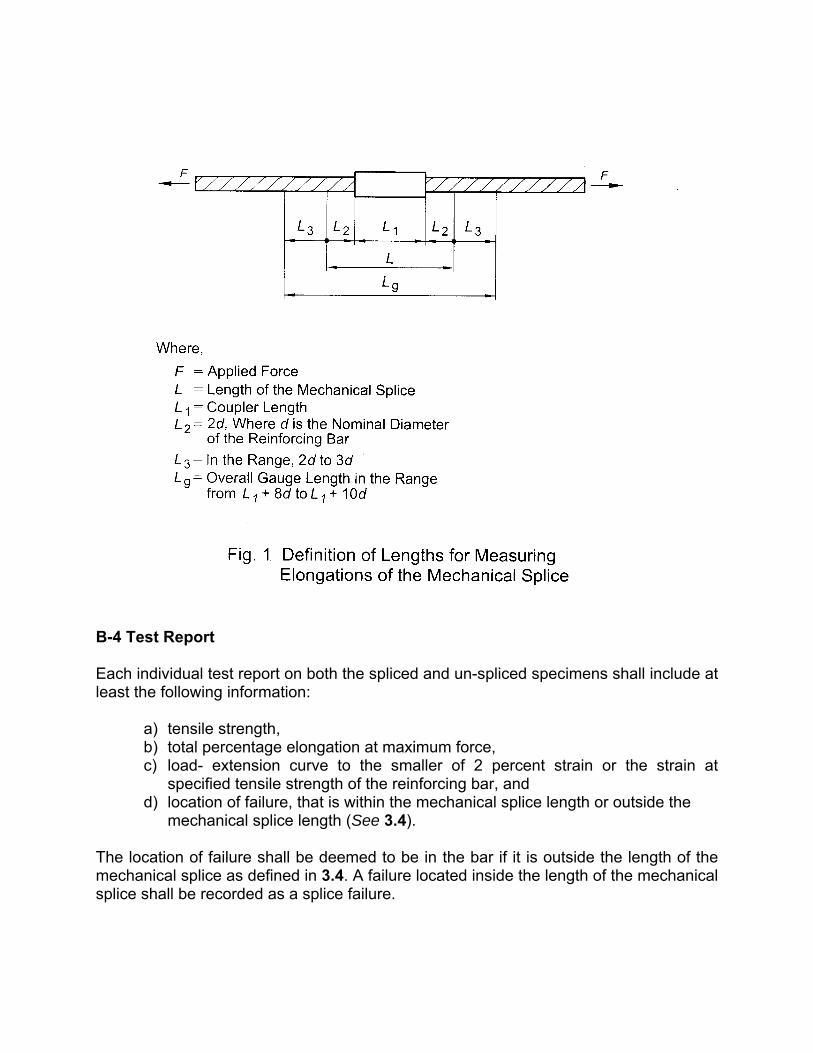
4905:1968 Methods for random sampling 6886:1973 Method for dynamic force calibration of axial load fatigue testing machines by means of a strain gauge technique 12872:1990 Metallic Materials— Verification of extensometers used in uniaxial testing 3 TERMINOLOGY For the purpose of this standard, the terms and definitions given in IS 1786 shall apply, in addition to the following: 3.1 Mechanical Splice— Complete assembly of a coupler, or an end bearing sleeve including any additional intervening material or other components providing a splice of two reinforcing bars. 3.2 Reinforcement Coupler— Coupling sleeve or threaded coupler for mechanical splices of reinforcement bars for the purpose of providing transfer of axial tensile force and/or compressive force from one bar to the other where a) coupling sleeve is a device fitting over the ends of two reinforcing bars, and b) threaded coupler is a threaded device for joining reinforcing bars with matching threads. 3.3 Coupler Length— Actual length of the reinforcement coupler including all load transferring parts, if more than one, and including lock nuts, if any. 3.4 Length of Mechanical Splice— Length of reinforcement coupler plus two times the nominal bar diameter at both ends of the coupler (see Fig. 1). 3.5 Slip— The permanent extension of a mechanical splice after being loaded to a defined load level. 3.6 Slip Measurement Device— The assembly constituted by the extensometer and any system used to fix it to the mechanical splice.
3.7 Tests 3.7.1 Type Tests Tests carried out to prove conformity with the standard. These are intended for product/type approval and are carried out whenever a change is made in the type of the reinforcement coupler or manufacturing process/ conditions or crimping method or forging or threading machine. 3.7.2 Acceptance Tests Tests carried out on samples taken from a lot passing type tests for the purpose of acceptance of the lot. 4 TYPES OF REINFORCEMENT COUPLERS There are various types of reinforcement couplers used in mechanical splicing of reinforcing bars in reinforced concrete constructions. Some of the commonly used mechanical splicing systems based on the type of reinforcement coupler used in them have been described in Annex A. 5 CLASSIFICATION
5.1 Reinforcement couplers supplied in accordance with this standard shall be classified into the following classes: a) Class L+H, and b) Class L. 5.1.1 Couplers which meet both low cycle fatigue test and high cycle fatigue test requirements of 9.5.1 and 9.5.2 respectively shall be classified and designated as class ‘L+H’ coupler. 5.1.2 All other couplers which meet only low cycle fatigue test requirement of 9.5.1 shall be classified and designated as class ‘L’ coupler. NOTE— Class ‘L+H’ couplers are recommended for use in concrete structures which are subjected to high cycle of fatigue like road bridges, railway bridges, machine foundations, slender structures like stack etc. For all other structures, reinforcement couplers of Category L are recommended. 6 MANUFACTURE Reinforcement couplers shall have adequate strength, length and internal threads as per manufacturer’s design to be able to meet the performance requirements of this standard.
7 WORKMANSHIP AND FINISH All reinforcement couplers shall be finished smooth and shall be free from burrs, cracks and other manufacturing defects. The threads shall be cleanly formed and shall be free from imperfections. 8 NOMINAL SIZES The nominal sizes of reinforcement couplers based on their internal diameter shall correspond to the nominal sizes of bars covered under IS 1786. 9 PERFORMANCE REQUIREMENTS 9.1 All reinforcement couplers shall meet the performance requirements of 9.2, 9.3, 9.4 and 9.5.1. Class ‘L+H’ couplers in addition to above shall also meet the requirements of 9.5.2. 9.1.1 The requirements apply to the reinforcement coupler even though the above tests on the coupler are carried out on a mechanical splice that has been installed in accordance with the manufacturer’s written instructions. 9.2 Static Tensile Test 9.2.1 Tensile Strength The tensile strength of the mechanical splice, when tested in accordance with the details given in Annex B shall not be less than 690 N/mm2. 9.2.2 Percentage Elongation The minimum percentage elongation at maximum force (also termed as uniform elongation) when measured in accordance with the method given in Annex B in the reinforcing bar outside the length of the mechanical splice shall be minimum 3% before the failure of the test piece. 9.3 Slip Test The total slip value measured in accordance with the test procedure described in Annex C shall not exceed 0.10 mm. 9.4 Cyclic Tensile Test The mechanical splice shall withstand 100 cycles of the stress variation from 5 percent to 90 percent of fy (where fy = 550 N/mm2) when tested in accordance with the details given in Annex D without loss of static tensile strength capacity when compared with like specimen. The static tensile strength capacity of the test piece shall be determined
by testing it statically to failure in accordance with the procedure given in Annex B after subjecting it to stress cycles.
9.5 Fatigue Test There are two types of fatigue tests namely low cycle fatigue test and high cycle fatigue test. All reinforcement couplers shall satisfy the requirement for low cycle fatigue test as specified in 9.5.1. Couplers of class ‘L+H’ in addition to above shall also meet the high cycle fatigue test requirement as specified in 9.5.2. 9.5.1 Low Cycle Fatigue Test The mechanical splice shall withstand 10 000 cycles of alternating tension and compression load when tested in accordance with the method given in Annex E. 9.5.2 High Cycle Fatigue Test for Class L+H Reinforcement Coupler only The mechanical splice, when tested in accordance with the method given in Annex E, shall withstand 2 000 000 cycles of varying axial tensile load with a stress range, 2 aσ , of 60 N/mm2 without failure. The upper stress, maxσ , in the test shall be 0.6fy, where fy = 550 N/mm2. 10 TESTS 10.1 Classification of Tests
10.1.1 The static tensile test shall constitute acceptance test. 10.1.2 The following shall constitute type tests:
i) Static tensile test, ii) Slip test, iii) Cyclic tensile test, iv) Low cycle fatigue test, and v) High cycle fatigue test for ‘L+H’ couplers only.
10.2 Selection and Preparation of Test Sample for Performance Tests 10.2.1 All tests specified under 10.1.1 and 10.1.2 and described in Annex B to Annex E shall be carried out on mechanical splices assembled in the manner as they are prepared for normal use. The above tests shall be conducted on selected sample to ensure conformity with the performance requirements laid down in 9.2 to 9.5. NOTE— Assembled and prepared for normal use implies to carry out the assembling according
to the manufacturer’s installation instructions.
10.2.2 A reference bar from the same heat and conforming to grade 550 D of IS 1786 shall be tested to determine its actual mechanical properties. The performance of some types of mechanical splices is dependent on the rib geometry of the steel reinforcing bar. The specified rib geometry shall be provided by the supplier and recorded with the test results. This requirement shall not apply to threaded couplers. 10.2.3 The test pieces shall be prepared according to the installation instructions provided by the manufacturer. The coupler shall be positioned in the middle of the test piece. 11 SAMPLING AND CRITERIA FOR CONFORMITY The sampling procedure and the criteria for conformity shall be as given in Annex F. 12 INSTALLATION INSTRUCTIONS The manufacturer/supplier shall provide written installation instructions. The installation instructions shall be clear and understandable. The described installation procedure of the reinforcement coupler shall be repeatable and able to achieve its performance under different job site circumstances. 13 IDENTIFICATION AND MARKING 13.1 Each reinforcement coupler shall be indelibly and clearly marked indicating class and nominal size of reinforcing bar for which it is intended. The manufacturer or supplier shall mark the reinforcement coupler in such a way that all finished reinforcement couplers can be traced to the original cast from which they were made along with the date of manufacture. Every facility shall be given to the purchaser or his authorized representative for tracing the reinforcement couplers to the cast from which they were made. 13.2 Each coupler should be identifiable by marks/ brands which indicate the name of the manufacturer or their brand name. 13.3 BIS Certification Marking 13.3.1 The reinforcement coupler may also be suitably marked with the Standard Mark. 13.3.2 The use of the Standard Mark is governed by the provisions of the Bureau of Indian Standards Act, 1986 and the Rules and Regulations made thereunder. The details of conditions under which a license for the use of the Standard Mark may be granted to manufacturers or producers may be obtained from the Bureau of Indian Standards.
Annex A (Foreword and Clause 4)
DIFFERENT MECHANICAL SPLICING SYSTEMS BASED ON TYPE OF
REINFORCEMENT COUPLER USED A-1 MECHANICAL SPLICING SYSTEMS BASED ON THREADED COUPLER A-1.1 In these types of mechanical splicing systems, the threaded ends of the reinforcing bar are joined together using internally threaded coupler (See A-1.1.1, A-1.1.2 and A-1.1.3). A-1.1.1 Mechanical Splicing Systems with Parallel Threaded Couplers A mechanical splice system with parallel threaded couplers is a one in which a parallel thread is cut or formed on the ends of the reinforcing bars, which are then connected by a coupler with matching parallel threads. With parallel threads, the strength of the assembly is directly proportional to the thread engagement length. No torque wrench is therefore required for assembling these types of mechanical splice systems. Hand tightening of the bar or coupler is sufficient. A-1.1.2 Mechanical Splicing Systems with Tapered Threaded Couplers A mechanical splice system with tapered threaded coupler is one in which the ends of the rebar are sawn square and a tapered thread is formed onto the bar to suit the taper thread of the coupler. With tapered threads, the strength of the assembly is not directly proportional to the thread engagement length: it is minimal at the beginning of the engagement and the full strength is reached only when the assembly is complete. A torque wrench is therefore required for assembling in these types of mechanical splice systems. The torque wrench used for the assembly of the coupler should be calibrated for the purpose. Sufficient workable space should be ensured for torque wrench movement. NOTE— At project sites, sufficient care shall be taken during installation of bar into the tapered threaded coupler so that cross-threading is avoided. A-1.2 As there is reduction in cross section of bar at the ends due to threading in above types of mechanical splicing system, nominal cross section at the threaded end shall be considered, thereby reducing the permissible stress in the reinforcement. A-1.3 In order to prevent any decrease in the end sections of the bar as a result of threading, the reinforcement bars can also be either:
a) upset at the ends by cold forging― By virtue of upsizing method, the nominal cross sectional area of the bar in the threaded region is not reduced after thread formation. Such splices can develop full strength of the reinforcement bar thereby ensuring bar break (See A-1.3.1); or
b) fitted with a threaded sleeve by crimping/swaging― Splicing systems with a special sleeve with internal threads is used for reinforcing bars with oblique, discontinuous, spiral ribs. This splice also develops full strength of the reinforcement bar and ensures bar break.
A-1.3.1 Mechanical splicing systems with upset parallel threaded couplers A mechanical splice system with upset parallel threaded coupler is one in which the ends of the bar are saw cut and then enlarged by cold forging, such that the core diameter of the bar is increased to a pre-determined diameter. A parallel thread is cut or formed onto the upsized/enlarged end of the reinforcing bar. The effective diameter of the bar at threaded end shall not be less than the nominal diameter of the parent bar, creating the conditions for failure within the bar and not in the coupled joint. No torque wrench is required for assembling this type of mechanical splice system. Hand tightening of the bar or coupler is sufficient to provide the tensile capacity of the splice. A-2 MECHANICAL SPLICING SYSTEMS BASED ON COUPLING SLEEVE A-2.1 Mechanical Splicing Systems with a Crimped Sleeve Use of mechanical splicing systems with a crimped sleeve is limited to relatively large diameter deformed reinforcing bars. It consists of the introduction of the bars to be spliced into a sleeve which is crimped by means of a hydraulic crimping tool onto the ribbed bars in order to fill the voids between them and the inner surface of the sleeve. The ribs on the bar penetrate into the relatively softer steel of the sleeve and the ribs work in shear. During crimping the sleeve lengthens, and the other reinforcing bar to be spliced should be displaceable at this moment. The size of the crimping device requires a bar interspacing of at least 10 cm. Splicing by crimping is also possible with reinforcing bars of differing diameter. The same method also enables threaded steel rods to be spliced to reinforcing bars using high strength threaded bolts. A-2.2 Mechanical Splicing Systems with Injected Sleeves These mechanical splicing systems are a special case of sleeve splicing; the stresses are distributed by the shear strength of the product injected between the ends of the bars to be sleeve spliced:
a) With the ‘Thermit’ sleeve the space between the deformed bars and the sleeve, whose internal surface is also ribbed, is tilled with a special molten metal. This molten metal is prepared in a crucible, which is in communication with the sleeve, by igniting a mixture consisting mainly of iron oxide and aluminium powder. The strength of the sleeve may be increased by using a larger sleeve
diameter. The sleeve is shorter but wider than that used in the crimping method. The bars are not in contact.
b) Similar method is the injection of grout or an epoxy resin between the sleeve and
the bars. The length of the sleeve is necessarily greater.
Annex B (Clause 8.2)
METHOD OF STATIC TENSILE TEST
B-1 PREPARATION OF TEST PIECE The test piece for the tensile test shall be prepared in accordance with 10.2. It shall be sufficiently long to ensure a free length between the grips of the testing machine to allow determination of percentage elongation at maximum force. The minimum sufficient free length of the test piece for the tensile test in millimeters is 400+ L, where L is the length of mechanical splice (See 3.4). B-2 TESTING EQUIPMENT The testing equipment shall conform to IS 1608. B-3 TEST PROCEDURE B-3.1 Tensile Strength The tensile strength shall be determined by means of a tensile test carried out in accordance with IS 1608. A tensile test on an un-spliced specimen from the same bar used for the preparation of spliced specimen shall be performed to establish actual tensile strength of the reinforcing bar. For the calculation of stresses, the effective cross-sectional area of the reinforcing bar shall be used. B-3.2 Percentage Elongation at Maximum Force The gauge length for determining percentage elongation at maximum force for both spliced and un-spliced specimens shall be the same. In both spliced and un-spliced specimen, it shall be located outside the length of the mechanical splice in both the bars (See Fig. 1). The percentage elongation at maximum force shall be tested and measured according to IS 1608 outside the length of the mechanical splice on both sides of the connection. Both values shall be recorded and the largest shall be used to assess conformity.
B-4 Test Report Each individual test report on both the spliced and un-spliced specimens shall include at least the following information:
a) tensile strength, b) total percentage elongation at maximum force, c) load- extension curve to the smaller of 2 percent strain or the strain at
specified tensile strength of the reinforcing bar, and d) location of failure, that is within the mechanical splice length or outside the
mechanical splice length (See 3.4).
The location of failure shall be deemed to be in the bar if it is outside the length of the mechanical splice as defined in 3.4. A failure located inside the length of the mechanical splice shall be recorded as a splice failure.
Annex C (Clause 8.3)
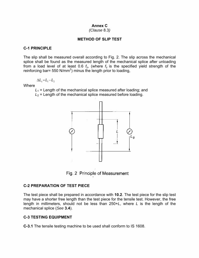
METHOD OF SLIP TEST
C-1 PRINCIPLE The slip shall be measured overall according to Fig. 2. The slip across the mechanical splice shall be found as the measured length of the mechanical splice after unloading from a load level of at least 0.6 fy, (where fy is the specified yield strength of the reinforcing bar= 550 N/mm2) minus the length prior to loading,
21s LLL −=∆ Where L1 = Length of the mechanical splice measured after loading; and L2 = Length of the mechanical splice measured before loading.
C-2 PREPARATION OF TEST PIECE The test piece shall be prepared in accordance with 10.2. The test piece for the slip test may have a shorter free length than the test piece for the tensile test. However, the free length in millimeters, should not be less than 250+L, where L is the length of the mechanical splice (See 3.4). C-3 TESTING EQUIPMENT C-3.1 The tensile testing machine to be used shall conform to IS 1608.
C-3.2 The extensometer used shall be of class 2 or better and shall be in accordance with IS 12872. The extensometer used to determine the slip shall be at least a two-point (averaging) type, but preferably a three-point (averaging) type. C-3.3 The slip measurement device shall be rigid enough, and fixed securely, so that the slip can be measured with an accuracy of not less than 0.01 mm. C-3.3.1 The accuracy of slip measurement device should be checked periodically (e.g. annually and always if there is a change in the testing conditions) by performing the test on a control bar with the same gauge length. The measurement accuracy is computed as the sum of the accuracy of the extensometer (as stated by its manufacturer) plus the error that could be generated by the fixing devices. If the slip measurement is done under load, the measurement accuracy is the difference between the measured and the calculated elastic elongation. If the measurement is done after load release, the measurement accuracy is the reading after the load is returned to zero. C-3.3 TEST PROCEDURE
a) The test piece shall be gripped in the tensile testing equipment in such a way that the load is transmitted axially and as much as possible free of any bending moment on the whole length of the test piece.
b) The slip measurement should be carried out without any preloading of the test piece. If a small preloading is unavoidable to clamp the bar, the preloading stress in the bar shall be less than 4 N/mm2 and the corresponding slip measurement, if any, shall be noted and included in the test report.
NOTE— Preloading of the test piece will normally take most of the slip out. A preloading does not normally occur for spliced bars in a structure. c) The slip measurement device shall then be attached such that the dial indicators
are 180º apart. Zero them out. d) The gauges shall be set to zero after closure of the jaws of the tensile testing
machine. e) An axial tensile load shall be applied such that the tensile stress in the reinforcing
bar equals 0.6 fy (fy = 550 N/mm2). The force to be applied shall be determined using the nominal cross-sectional area of the reinforcing bar. The load shall be maintained until a steady reading is obtained on both dial indicators.
NOTE— The recommended maximum speed of loading is 500 MPa/min. f) The load shall then be reduced to 20 N/mm2 and the readings of the two
extensometers shall be taken. g) Sum the value of the two readings and divide the resultant sum by two. The
result shall be reported as total slip. h) The slip measurement device shall then be removed and an axial tensile load
sufficient to cause failure of the test piece shall be applied to it. j) The load shall be recorded and the type and location of failure and any necking
of the bar shall be noted. The maximum load attained shall be recorded as maximum test load.
Annex D (Clause 8.4)
METHOD OF CYCLIC TENSILE TEST
D-1 PREPARATION OF TEST PIECE The test piece shall be prepared in accordance with B-1. D-2 TESTING EQUIPMENT The testing equipment shall conform to IS 1608. D-3 TEST PROCEDURE D-3.1 The test specimen shall be subjected to 100 cycles of stress variation from 5 percent to 90 percent of the specified minimum yield strength of the reinforcing bar, fy (fy = 550 N/mm2). One cycle is defined as an increase from the lower load to higher load and return. The load shall vary cyclically according to a sinusoidal wave-form of constant frequency. D-3.2 If the specimen does not fail at the end of 100 cycles, the axial tensile load shall be increased statically to cause failure in the specimen and its static tensile strength capacity shall be determined in accordance with Annex B.
Annex E (Clause 8.5)
METHOD OF FATIGUE TEST
E-1 The purpose of fatigue testing of mechanical splices for steel reinforcing bars is to determine the fatigue strength of the mechanical splice. The fatigue performance of a mechanically spliced bar will normally be lower than that of the un-spliced bar. E-2 PREPARATION OF TEST PIECE The test piece for the fatigue test shall be prepared in accordance with 10.2 and shall be sufficiently long to ensure a free length between the grips of the testing machine, which is larger than the length of the mechanical splice. E-3 LOW CYCLE FATIGUE TEST E-3.1 Test Procedure
The fatigue test shall be conducted on the sample by loading it to +173 MPa to -173 MPa for 10 000 cycles. The load shall vary cyclically according to a sinusoidal wave-form of constant frequency. If the specimen does not fail at the end of 10 000 cycles, the axial tensile load shall be increased statically to cause failure in the specimen and its static tensile strength capacity shall be determined in accordance with Annex B. E-4 HIGH CYCLE FATIGUE TEST E-4.1 Principle In the high cycle fatigue test, the test piece is subjected to an axial tensile load which varies cyclically according to a sinusoidal wave-form of constant frequency in the elastic range. E-4.2 Testing Equipment The fatigue test shall be carried out by means of a hydraulic ram under load control. The fatigue testing machine shall be calibrated as per IS 1828 (Part 1) and the accuracy shall be ± 1 percent or better and the machine shall be capable of maintaining the upper stress level, maxσ , within ± 2 percent of the specified value and the lower stress level,
minσ , within ± 2 percent of the specified value. E-4.3 Test Procedure
a) The test piece shall be gripped in the testing equipment in such a way that the load is transmitted axially and as much as possible free of any bending moment on the whole test piece.
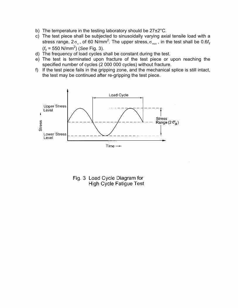
b) The temperature in the testing laboratory should be 27±2°C. c) The test piece shall be subjected to sinusoidally varying axial tensile load with a
stress range, 2 aσ , of 60 N/mm2. The upper stress, maxσ , in the test shall be 0.6fy
(fy = 550 N/mm2) (See Fig. 3). d) The frequency of load cycles shall be constant during the test. e) The test is terminated upon fracture of the test piece or upon reaching the
specified number of cycles (2 000 000 cycles) without fracture. f) If the test piece fails in the gripping zone, and the mechanical splice is still intact,
the test may be continued after re-gripping the test piece.
Annex F (Clause 10)
SAMPLING AND CRITERIA FOR CONFORMITY
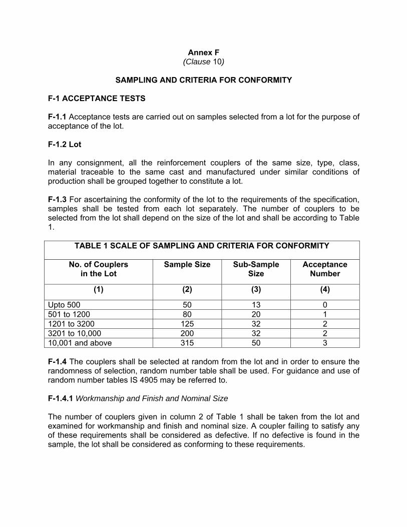
F-1 ACCEPTANCE TESTS F-1.1 Acceptance tests are carried out on samples selected from a lot for the purpose of acceptance of the lot. F-1.2 Lot In any consignment, all the reinforcement couplers of the same size, type, class, material traceable to the same cast and manufactured under similar conditions of production shall be grouped together to constitute a lot. F-1.3 For ascertaining the conformity of the lot to the requirements of the specification, samples shall be tested from each lot separately. The number of couplers to be selected from the lot shall depend on the size of the lot and shall be according to Table 1.
TABLE 1 SCALE OF SAMPLING AND CRITERIA FOR CONFORMITY
No. of Couplers in the Lot
Sample Size Sub-Sample Size
Acceptance Number
(1) (2) (3) (4)
Upto 500 50 13 0 501 to 1200 80 20 1 1201 to 3200 125 32 2 3201 to 10,000 200 32 2 10,001 and above 315 50 3 F-1.4 The couplers shall be selected at random from the lot and in order to ensure the randomness of selection, random number table shall be used. For guidance and use of random number tables IS 4905 may be referred to. F-1.4.1 Workmanship and Finish and Nominal Size The number of couplers given in column 2 of Table 1 shall be taken from the lot and examined for workmanship and finish and nominal size. A coupler failing to satisfy any of these requirements shall be considered as defective. If no defective is found in the sample, the lot shall be considered as conforming to these requirements.
F-1.4.2 Static Tensile Test F-1.4.2.1 The lot having been found conforming to requirements of workmanship and finish and nominal size as per F-1.4.1 shall be tested for static tensile test. For this purpose sub-samples as given in column 3 of Table 1 shall be taken and subjected to this test. The number of couplers required in the sub-sample may be taken from those already tested and found satisfactory according to F-1.4.1. F-1.4.2.2 The lot shall be considered to have satisfied the requirement of static tensile test as per F-1.4.2.1 if the number of defective couplers found in the sub-sample is less than or equal to the corresponding acceptance number given in column 4 of Table 1. F-2 TYPE TESTS F-2.1 Type tests are intended to prove the suitability and performance of a new type of coupler or a new manufacturing process. Such tests therefore, need to be applied only when a change is made in the type of the coupler or in manufacturing process/ conditions or crimping method or forging or threading machine. F-2.1.1 Slip Test For this type test, the manufacturer or the supplier shall furnish to the testing authority a minimum of three samples of coupler of the largest size, three samples of the medium size and three samples of the smallest size (selected preferably from a regular production lot). F-2.1.1.1 The samples so selected shall be tested for compliance with requirements of slip test as given in 9.3. F-2.1.1.2 If all the samples pass the requirements of slip test, the type of coupler or the change under consideration shall be considered to be eligible for type approval which shall be normally valid for a period of one year. F-2.1.1.3 At the end of the validity period (normally one year) or earlier, if necessary, the testing authority may call for fresh samples for type test for the purpose of type approval. F-2.1.2 100 Cycle Test For this type test, the manufacturer or the supplier shall furnish to the testing authority a minimum of three samples of coupler of the largest size, three samples of the medium size and three samples of the smallest size (selected preferably from a regular production lot). F-2.1.2.1 The samples so selected shall be tested for compliance with requirements of 100 cycle test as given in 9.4.
F-2.1.2.2 If all the samples pass the requirements of 100 cycle test, the type of coupler or the change under consideration shall be considered to be eligible for type approval which shall be normally valid for a period of two year. F-2.1.2.3 At the end of the validity period (normally two year) or earlier, if necessary, the testing authority may call for fresh samples for type test for the purpose of type approval. F-2.1.3 Low Cycle Fatigue Test For this type test, the manufacturer or the supplier shall furnish to the testing authority a minimum of three samples of coupler of the largest size, three samples of the medium size and three samples of the smallest size (selected preferably from a regular production lot). F-2.1.3.1 The samples so selected shall be tested for compliance with requirements of low cycle fatigue test as given in 9.5.1. F-2.1.3.2 If all the samples pass the requirements of low cycle fatigue test, the type of coupler or the change under consideration shall be considered to be eligible for type approval which shall be normally valid for a period of two year. F-2.1.3.3 At the end of the validity period (normally two year) or earlier, if necessary, the testing authority may call for fresh samples for type test for the purpose of type approval. F-2.1.4 High Cycle Fatigue Test (for Class ‘L+H’ Coupler only) For this type test, the manufacturer or the supplier shall furnish to the testing authority a minimum of three samples of coupler of the largest size, three samples of the medium size and three samples of the smallest size (selected preferably from a regular production lot). F-2.1.4.1 The samples so selected shall be tested for compliance with requirements of high cycle fatigue test as given in 9.5.2. F-2.1.4.2 The following acceptance criteria shall be complied with:
a) if all the samples pass the requirements of the high cycle fatigue test, the type of the coupler or the change under consideration shall be considered to be eligible for type approval which shall be normally valid for a period of two year;
b) if one test sample fails the test three additional samples of the same type and size that have failed shall be tested. If all three additional test samples pass, the test is passed and the type of the coupler or the change under consideration
shall be considered to be eligible for type approval which shall be normally valid for a period of two year;
c) if two or more test samples fail the fatigue test, the test is failed. F-2.1.4.3 At the end of the validity period (normally two year) or earlier, if necessary, the testing authority may call for fresh samples for type test for the purpose of type approval. F-2.1.5 The sampling and criteria for conformity for workmanship and finish, nominal size and static tensile test shall be in accordance with F-1.


![Interdisciplinary Research Book · 2018. 4. 25. · Interdisciplinary Research Book [8] Vidyamrut (ISBN978-93-84659-37-0) »Ö×»ÖŸÖ ¾ÖÖ›ü:´ÖµÖ ¯Ö úÖ¸üÖ´Ö¬µÖê](https://static.documents.pub/doc/80x56/60e1c3be1fd29142ca4913e9/interdisciplinary-research-book-2018-4-25-interdisciplinary-research-book-8.jpg)


![·Ö˘üÖ‚üÖ´ŽÒü ¿ÖÖˆÖ›Ö ‚üÖŁÖflÖ¡Ömahafireservice.gov.in/Site/PDFs/ActsAndRules/Maharashtra...‡ÖÖ’Ö ƒÖıü] ·Ö˘üÖ‚üÖ´ŽÒü ¿ÖÖˆÖ›Ö](https://static.documents.pub/doc/80x56/5af2c6717f8b9ad061911fe6/z-l-fi-z-l-fs-oeoe.jpg)


![F:8 gb flash 31-05-2012Noorul Huda oor ul hudaTajdar-e ... Karbla.pdf · ÜÜÜnnnûûûÜûuuuuôôônô†††$$$$ÖÖ†Ö]]]Ö]àààôôôôÛÛÛFFFàFuuuuøøøÛø†††$$$$ÖÖ†Ö]]Ö]ääääôôô]ô×××###ÖÖ×Ö]]Ö](https://static.documents.pub/doc/80x56/5eab36cff01e01439d645ad5/f8-gb-flash-31-05-2012noorul-huda-oor-ul-hudatajdar-e-karblapdf-oeoeoennnoeuuuunaaaaffffuuuuaaaa.jpg)


![M.E. (Full time] · M.E. (Full Time) Prospectus No. 131736 ÃÖÓŸÖ MÉÉb÷MÉä ²ÖÖ²ÖÖ †´Ö¸üÖ¾ÖŸÖß ×¾ÖªÖ¯Ößšü SANT GADGE BABA AMRAVATI UNIVERSITY +¦ªÉɺÉGòʨÉEòÉ](https://static.documents.pub/doc/80x56/5e93be592fde4361df418cfa/me-full-time-me-full-time-prospectus-no-131736-f-mbm.jpg)


