AR ffIECINICAL INTELLIGENCE 0* TRANSLATION (Title Unelaseti ed) INTz2I0I' BALLISTICS by E. . Serevryakov state Printing House of .he Defense Industry Moscow, 19)i9, 2nd Ea tion 672 Pages (Part 2 of 10 Parts, Pape 8"&172) MATE AIR TCHNICL NELLIGNCE ETE WRI~H*PATESU AIUOCEBS OCHI2Of F~TS-.7OHIO B sAvailjable COPY Di~tributior'i of thi:-;~i i u~nlimited. It ri be reloaoud to the "Le~a ir h1.ooj, Depart, n.I Reproduced by th of ;o-nmrcol for galu to the CLEARiNGHOUSE for Federal Scientific & Technical CenelU'I public. Informaiion Springfield Va. 22151 m il 1 411 I-~~~~V '-- --.- v -
Transcript
AR ffIECINICAL INTELLIGENCE0* TRANSLATION
(Title Unelaseti ed)INTz2I0I' BALLISTICS
by
E. . Serevryakov
state Printing House of .heDefense Industry
Moscow, 19)i9, 2nd Ea tion
672 Pages
(Part 2 of 10 Parts,
Pape 8"&172)
MATEAIR TCHNICL NELLIGNCE ETE
WRI~H*PATESU AIUOCEBSOCHI2Of
F~TS-.7OHIO B sAvailjable COPYDi~tributior'i of thi:-;~i i
u~nlimited. It ri be reloaoudto the "Le~a ir h1.ooj, Depart, n.I
Reproduced by th of ;o-nmrcol for galu to theCLEARiNGHOUSE
for Federal Scientific & Technical CenelU'I public.Informaiion Springfield Va. 22151
m il 1 411
I-~~~~V '-- --.- v -
MMOR ALLISICS
BYI
STATE FINTI OSRO BALISISEIXSM
.4 .3? ...
CIUAPTYR 711 - "CALCULAI ING "!M IFAT LIST TO Ti:EWALI.S DURING URNING 01' IO OMI, 1,N A CIa1,.1J CIAV,1iQ(
When powder iti btirned in a closed chanber (in a bomb), t portitn
of the heat energy is lost on heating the walls of the bomb. As a
-- ,result, the pressure p. developed by the gases is somewhat lower than
the theoretical pr-ssure; the latter would be obtained If all the
thermal energy emitted during the combustion of .the given powder were
utilized to increase the pressure of the gases.
This loss of heat depends on a number of loading factors.
Experiments conducted by professor S.P. Vukolov in the Naval
Technical Research Laboratory back in 1895 and 1896 had shown that
at La.- 0.20 the pressures p. developed in a standard bomb and in a
bomb whose interior surface was lined with a thin layer of nonconductive
mica were different. The resultant pressures were: 2033 kg/cm 2 iu
the bomb wtthout the mica layer- and 2202 kg/cm 2 in the bomb containir
tL~e mica, the difference - 169 kg/cm 2 - comprises about 8%.
It was stated prev'.ously(in the theory of powder combustion), in
the discussion of problems relating to powder ignition in a gun,'that
the contact of the powder grains with the cool surface of the chamber
slows down the ignition process.
The following simple experiment in the open air will show this to
be true. If a strip of powder is zlamped vertically in a locksmith's
metal vise and iguited from the top, the process of burning will be
:rrested-upou reaching the vise. The jt-ip will be extinguished :I
because a considerable portion of the heat is t1ken up by the cold
met 1.
F-TS-7327-RE" 84,I-
" .4
it i*-j.known thnc a rionsi,,ul taneous ignition distorts te initial
yhane of the grain and c'tuses d,:vla't-ions from tbe ideal law of
coubus tion. Cozsequently, the transfer qf heat to the walls should
have an effect not only on the mngnitu/e of pressure, but also on/
the character'of its development.
By disregarding loss-ei in a bomb due to heat transfer we commit
an error in the determination pm and, consequently, aL error in the
magnityde of energy f and covolume a determined on '41e basis of
experiments with a manometric bomb.
In view of this heat transfer, Nobel's formula will hold true
for pressures above 1000 kg/cm2 . At lower pressures, corresponding'.,:
PD'to. charging densities of4 <0.10, the points in the diagram
versus pm will fal .below the s'traight line relationship expressed
Pby the known equation f . f 4 ap3.
Systematic experiments conducted by assistant A.I. Kokhanov in
1933-,-at charging densities of from 0.015 to 0.20, have shown that a
hyperbolic curve abc, approaching asymptotically the stfaight line dePm
(fig. 16), is obtained in the system of coordinates E pm instead
of a straight line. The smaller the value of A , the greater is the
deviation from the theoretical relat'nship,
The results obtained! in determining the powder energy f and
covolume a may therefore differ, depending on the charging densities
at which the tests were conducted. The higher the value of 6 , the
greater will be the magnitude of f and the smaller the covolume a
(points b and c). And, conversely, small values of,- shold produce
a small energy and a large covolume (points a and b).
F-TS-7327-RE 85
_Q&, 40-.
Our experimeits have also disclosed the foliouing.
If a powder of the same composi'tion but of different thickness
is burned in a bomb at the same value of &, the nmaxriuw prescure p
will, be the lower tL-e thicker the powder. Therefore, the energy
produced by thick powders,.determined without taking the heat losses
into consideration, will also be the smaller, the .thicker the powder.
This can be explained by.the fact that a thick powder burns longer
and, consequently, a larger portion of the heat is transmitted to the
walls of the bomb.
If an identical powder is burned at the same A in bombs of
different'sizes, the value of p will be higher in the larger bomb,
because the surface per unit weight of powder charge is smaller in
the larger bomb, and hence the heat losses will be smaller in it.
All of these facts confirm the presence of cooling through the
walls of the bomb. The considerable number of tests conducted by
various investigators made it' possible to-determine quantitatively
the corrections to be Introduced in the charging of powders of various
thickness under different conditions of loading, in order to obtain
pressures corrected for heat transfer. Although these corrections
are not final, nevertheless their Introduction served to explain the
phenomena discussed aboVe-; Miuraur's correction may be considered
to be the best founded among corrections of this type.
F -TS-7327-RE 86
-
oiS
HIC REPRODUCIBLE
Pil
A 1 1'
Fig. 16 - - as a Function of P , According
to Kokhanov.
According to Miuraur the heat loss through transfer is pro-
portional to the number of collisions between the powder gas molecules
and the walls of the bombp and th4.s number is in-turn proportional
to the surface of the bomb S4 , pressure p and time t. For a
fluctuating pressure, the loss is proportional to $ and pdt. Also,
because )pdt does not depend on &, the loss of heat &Q through
* the surface of walls Si is constant for any powder charge Ci ort .
This was confirmed by Miuraur who conducted tests at different
values ofSA. Inasmuch as the total quantity of the heat evolved is
proportional to the weight of the charge'i, the relative loss Q
is inversely proportional totj or.6. Consequently, .2Qis pro-J' Qportional to pdt.
The magnitude of maximal pressure at a given value of Ciis
I- governed by the volume of the bomb(*). Actually, an n% pressure
(*) Consequently, magnitudesf and a will also depend on the volumeof the homO, in which the combustion takes place, while the magnitudeof 5 pdt should not change because of cooling through the walls ofthe bomb.
F-TS-7327-R 87
'i -.
drop entails a corre-sponding pro)otgatlot of the period of burnig;
tho curve "p,t becortes distorted, but the itrea I pdt remalls unchangegd.
All this was checked and verified by our tests with bomibs of
different sizes. The following important deduction can be reachedel
from the above: the rate of burning u1 - can be determined
pdt
with the same degree of accuracy in both large and small. bombs,
regardless of the heat lost through the walls.
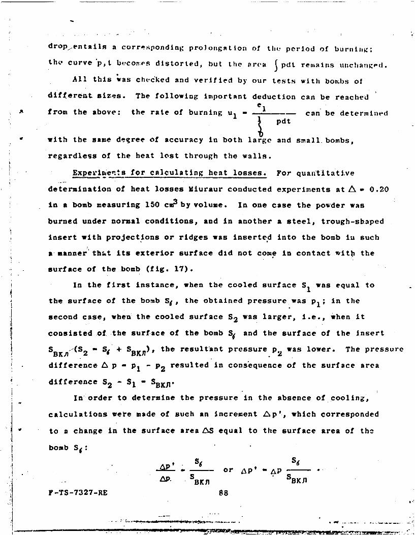
Experiments for calculating heat losses. For quantitative
determination of heat losses Miuraur conducted experiments at A- 0.20
in a bomb measuring 150 cm3by volume. In one case the powder was
burned under normal conditions, and in another a steel, trough-shaped
insert with projections or ridges was inserted into the bomb ia such
amanner tht its exterior surface did not come in contact witb the
surface of the bomb (fig. 17).
In the first instance, when the cooled surface SI was equal to
the surface of the bomb Si. the obtained pressure was p,; in the
second case, when the cooled surface S2 was larger, i.e., when it
consisted of the surface of the bomb S and the surface of the insert
SBK (S2 - S + 5BKn), the resultant pressure p2 was lower. The pressure
difference & p - p1 - P2 resulted in consequence of the surface area
difference S2 - S1 -BKJ .
In-order to determine the pressure in the absence of cooling,
calculations were made of such an increment Lp'l, which corresponded
to a change in the surface areaLAS equal to the surface area of the
bomb Si:
. Se S6- - or Ap' AP
. SBK ) BKF-TS-7327-RE 88
i! ..... -
-
In this mnanner, pressure p1 + Ap' would corre.ipond to the
• urf;ict. S - 0, i.e., it would correspond to the cofldition in which
io-,,.; d , e to hea t t r~insfer were a1bsen t
Ki4owlng p, and ,Ap', Miuraur determin.'d the relative correction
for _ p' APm T i'acntnfor heat transfer - -- , which was equal to A- in a constant..... p P T1
volu e.
Such tests conducted wirh a large numbor of powders of varied
thicknesses and properties established the significant dependence of
pressure lo-. -=-=k on the time of powder burning at A - 0.20, thePm ~2/
magnitude S6 /w j in these tests being equal to 7.774 cm2/g- 77.74 dm 2/kg.
The experiments were conducted with cylindrical crushers.' Very
strong igniters of gunpowder were used to determine the actual powder• c2
burning time tk . The igniters developed a pressure of Pn ow 250 kg/cm
which provided the crusher with small residual compression.
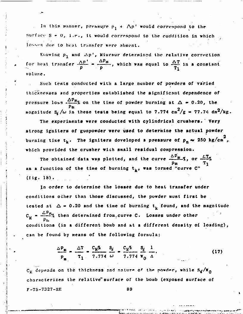
A LTThe obtained data was plotted, and the curve -T Pm . or-%
Pm TIas a function of the time of burning. tk, was termed "curve C"
(fig. 18).
In order to determine the lossee due to heat transfer under
conditions other than those discussed, the powder must first be
tested at A - 0.20 and the time of burning tk found, and the magnitude
CM - then determined from.curve C. Losses under other
conditions (in a different bomb and 4t a different density of loading),
can be found by means of the following forrjula:
A LT CM% S6 C% 6 1 (
m - M (17)
P5 T1 7.774 CJ 7.774 W A
Cy, depends on the thickness -nd nintur of thoe powde r, while Sl/w
characterizes the relative-surface of the boiab (exposed surface of
F-TS-7327-RE 89
uonbh) and cain bc catlcul;ted 'Is the exposed surt;,ce of :a urj:i -ur ;;
cy itnde r ( 2 #i - d, .'n;,'h -I('); t. u'' Ict rIz 'ir -uad It , ,t iU.,,I:I,
SC _ 2 + .. .3.Wo 1 d :• d c
The relative surface of the bomb diu,inishes ab the disnicter d anI
length 2c are incraetd. When volume W0 is increased 8 tinses, SdW 0
diminishes approximately by one half.
Formiula (17) shois that An a given bo~ub increases as A is
reduced and hence the tosm-.; are partic,larly hig/ at low values of A.
Fig. 17 - Test Arrangement Fig. 13 -Cure .for Calculating Losses .due Characterizing the Losses Due
to Heat Transfer. to Heat Trarsfer (according"to Miuraur).
* Ordinate: pressure loss in 5; .abscissa: milliseconas; 1)curve "C.'
Large igniters are not necessary when working with conical
crushers, because almuost instantaneous ignition results at the low
value of p 100-120 kg/cm2 .
Therefore, Miuraur's data ciinnot be directlt applied to our test
results and to powder tests for determining heat transfer, without
conducting special tests. However, using the theoretical formula as
a baiis, it is possible to compute the burning time at d - 0.20 and
PB o 250 kg/cm 2 and to determine the order of the coefLtcient values
C4 for powders of various thicknesses, in order to introduce the
necessary correction for heat loss.
The table presented below contains the results of sucil calculations,
F-TS-7327-RE 90 "-
=i i9
ub 1nt i 'd t Iof CIIIV* C.
wat, de.- Le 11J (t fr ow formju I,:
t 2.303t logP13
whereeC
7. "I 1 - 1 1
u. f A Ul P
(for a powder with a cons~tant burning surface area) (Table 8).
Table 8 - Values 0of coefficient CM for pyroxylin powders
Thicknass of powder 0.30 0.30 0.40 1.00 2.00 4.002e1 in mm flegme.
1 - 0.15; pl 1433;.-i = 9:570 Without correction for heattransfer lossesf - 800,000 kg-dm/kg;
P2 m3A 0.25; p 2 - 2756; 11,020 a 1.096 dm /kg.
We shall now calculate the corrections for f and a taking the heat-
transfer into account:
2756 1433
0.15 0.25- 0.6692 - 0.6692 18,350 - 5730 -6.4;
f 2756 - 1433 1323
fO 0 f (1 800,000 1.064 - 852,000 kg-dm/kg;
2 2dc -- f D 0-o,000 •0.006692 -- 0.1085;
P1P2 143,300 " 275j600
a cia O + ba - 1,096 0.1085 - 0.9875'2' 0.99.F-TS-7327-RE 97
T.o
CHAPTE.R IV - THEv LAW OF GAS FORMATION
I. DEFINITIONK
The study of the law of gas fcrmati. under the simplest conditions,
inFU a constant volume,. permits the application of the obtained relation-
-.9hps to the determination of pressure in the bore of a weapon when the
;-tgu-i's fired, iee., under conditions of variable volume.
The general pyrostatics formulaC
fw*4 fc4'
p 1 ,
shlows-that the magnitude of gaspressure at given conditions of
loading (V,, , f, a, 6) Is governed by the amount of the burned,OK
portion of the chargej' where wt jis the gravimetric inflow of
powder gases at a given instant,, and fw? jis the inflow of the energy
contained in this quantity of gas.
-keeping In mind that Wqj varies slightly under conditions prevailing
-In a manometric bomb, it may be said that the pressure is almost
proportional to the burned portion of the charge t at the given jpowder energy f andthe given loading density.*
Correspondingly, the nature of pressure increase in time .Runderdt
the same conditions of loading is also determined in 'the main by the
change of magnitude d+with time.dt
40 The law of gas formation is a term defining the change of the
magnitude of +I'with time and of its derivative L1known'as the "ratedc'
: of gas formation" or "'volumetric rate of burning."
F-TS-7327-RE -98
An analysis of thsis magnitude dmnikes it possible to determineI dt
the means by which the gas inflow during burning of powder can be
regulated,
2. ILATE OF GAS FO,ATION
We shallk4drive the formula for the rate of gas formation, based
on the burning of powder in parallel layers.
Let us assume that the burning of a powder grain of arbitra.ry
shape proceeds in concentric layers at a constant rate in all directions.
At some instant the grain, whose initial volume is Al and whose
initial surface is Si, has a volume A and a surface S (fig. .).
We shall also assume thu. a layer of thickness de is burned during the
time interval dt. Then, the volume burned during the time interval
dt will be expressed by formula:
d A Sde,cr
whencee
cr " Sde;
0
Acr Sde
AcA 1
Differentiating both sides of this equality vith respect tc t,
we gst:
F-TS-7327-RE 99
i ... . .... . . . .. ..
d4' Sde S
d ,dt dt t dt A
• . Mutiplying and dividng the right side by S1 , we get:
- /dt "l s
//
The first two mUltiples in the right side of the expressiodepend
on the geometry of the powder grain:
the initial exposed area of tho powder grain or the specific
surface per unit grain volume at the start of burning; it
will be shown later that this area depends *on the form and
the dimensions of the grain;
. - - the relative surface of a powder grain; it varies during
burning and depends only on the form of the grain and on
the relative thickness Of -thet-rnt powder layer, but not-on
its absolute dimensions.
As will be shown later' the third multiple, the linear rate of
deburningti - T dependson the type of powder' the pressure under
which the powder burns, and on its temperature.
In order to determine the rate of burning ir an actual tiest bomb
,under variable pressure, it is necessary to know the thickness
variation of the burning layer per unit of time, and to this end.it is
necessary "to establish the purely geometrical relation between the
.thickpess of the burned layer and the volume of the powder gases in
their various forms.
F-TS-1327-RE 100
MI I. .. . . - - . . ' . . ... . - t' -- a,'.-,- - , '~ , ,Fe. e ,
GRAPHIC NOT REPRDUCIBLE
Fig. 20 - Diagram of Powder Burning in Parallel Layers.
If the pressure curve plotted as i function of time-, or a table of
the values of p versus t is available from the bomb test, the values
of T,, t can be calculated by means of the general pyrostatics formula
(or from special tables), following which the geometrical law of
burning can be applied to establish the relationship between the
thickness of the powder, the value of * and S, and to derive theS1 1
dependence of the initial exposure --- on the form and dimensions ofAl
the grains. The numerical differentiation of t and e with respect
to time t will permit obtaining from the experiment the rate of gas
formation and the linear rate of burning, as well as their variation,
during the burning of the powder.
The establishment of all these relationships will facilitate the
analysis of those factors which can be used to control the quantity
and the intensity of gas formation during the burning of powder and
therefore, will permit the control of the phenomena of a gun discharge.
F-TS-7327-RE 101
- ... . .. . . . 4 p- ', r c, . .'t , , - - . ,
3. THE EFFECT PRODUCED BY THE GEOMETRY OF A POWDER GRAIN ON
GAS FORMATION
"" The inflow of gases per unit of time for a powder of a given type
a(f # s o, u1) can be regulated by the loading density or by the
* dimensions and the shape of the powder grains.
The effect of the geometry of the given grafns on the rate of
gas form'ation depending on the thickness of the powder burned at the
given instant, can be determined by means of the basic conditions of
the geometrical law of combustion.
The geometrical law of combustion permits determining the
.relationship between the relative thickness of the powder burned at
the given instant z - e the burnt portion of the grain A -
*~~ +A ben th voue, h
(A. being the volume of the burnt portion of the powder), and the
relative surface of the powder - S/S1 at the same instant. The
dependence of the roduct 1 on the shape and the diensionss S o
of the powder (gra n) can be established at the same time, which
product enters the formula for determining the rate of gas formation
and has a great effect on the law governing the gas pressure development
during a discharge,
A. Relation Between the Burnt Portion of Powder !' and the
Relative Thickness of Powder z, Consumed at the Same Instant
tw (Inflow of Gases)
Investigations ow that the dependence of on z for all forms of
powder is expressed b a formula of the same type(*)s
(*) In deriving this f rmula for one grain, as well as for an entirecharge composed of man 'grains, it is assumed that all grains of the
.chaxge have strictly Id ntical dimensions and are regular in form, thelatter being bounded by parallel planes, intersecting at right anglesor by surfaces of revol tion whose axes coincide or are parallel toeach other.
F-TS-7327-RE 102
(1 ( Xz Lz 2 ), (22)
where L, , tx are shape characteristics - constanf values depending
on the shape of the grain; they possess a particular numerical value*
for each grain shape inherent to the given grain form.
The thickness of the burnt layer e varies during burning frora
0 to e,; the relative thickness z varies from 0 to 1; and the relative4
volume fluCtuates between 0 and 1. / n
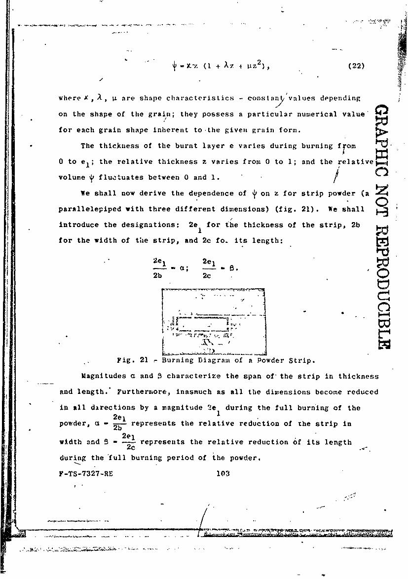
We shall now derive the dependence of y on z for strip powder (a Zc
parallelepiped with three different dimensions) (fig. 21). We shall
introduce the designations: 2e for the thickness of the strip, 2b
for the width of tie strip, and 2c fo. its length:
2e, 2e1-a; -s
2b 2c 0
I s - " ' - -- -
Fig. 21 - Burning Diagram of a Powder Strip.
Magnitudes a and characterize the span of the strip in thickness
and length.* Furthermiore, inasmuch as all the dimensions become reduced
in all directions by a magnitude 2e during the full burn'ing of the2e1 I
powder, a - 2 represents the relative reduction of the strip in
2elwidth and 5 2c represents the relative reduction of its length
during the full burning period of the powder.
F-TS-7327-RE 103
Inasmuch as
2e < 2b <2c,1
I> a> 1> 0.
Let us assume that at the given instant a layer of powder of
thickness e will be burned on all sidea. The volume burned can be
determined more easily as the differer.ce, between the initial volume
A1 and the remaining volume A .
We will have (see fig. 21):
Ac A,.' - ^ocr Aoc ":t -
A, Al
A -2e 1 2b 2c;.
(2e - 2e) (2b - 2e) (2c - 2e);
--~r e- 1 e be c - e0
AI e b1(
but
* • el e e e I
e b be c c e1
then
'ocr . 1-z) (1-%z) (1- Pz).!
F-TS-7327-RE 104
&
Upon removing the parentheses we obtain;
2 2
A 1
Substitu'ing this expression in the formula fort, we find:
(1 + a + 5)z - (a + s + aQ)z 2 + agz3 '
or, reducing it to the general form of equation (22), we get:
.... + + "B aB 2
+ a+)zI a+ +a+ l
Introducing the designations
+a - + + ~ -S=A; a: - it (23)
we obt in a general type formula:
= (1,.! + )Lz + z2).
At the end of burning att z '. 1 4- 1, and formula (23) assumes
an equality in the form
1 - x (1+ A + gL), (24)
which must be satisfied by the umerical characteristics 9 and IL.
F-TS-7327-RE 105
o -
This equality serves to verify the values of the characteristics
calculated by ateans of formula (23).
The characteristicsX, A and p. depend on the ratio of the
-dimensions, the-shorter and the narrower the strip, the greater is
a and f; the' longer the strip, the closer isie to unity and ) and ji
to zero, 4 -=
2. The Law Governing the Change of the Powder Surface When thePowder is Burned.
Formula (22) is a general formula for all powder shapes; the
difference will be only in the numerical values of the characteristics
','• IL and g. Using this formula as a basis, we shall derive a form-
ulafor depicting the relative surface - and the initiai exposure
, characterizing the effect of the shape and dimensions of the
powder on the rate of gas formation.
Differentiating t with respect to z, we find:
= ( 1 + 2Xz + 34z2 ). (25)
Inasmuch as
• dt de .
dz dt de dz'
and
1 u, dt I de de
dt A 1 " s de u 8z de el ,
e,
F-TS-7327-RE 106
-JA
then
4 S1 S el S1 Sdd - u ---e
dz A s u A S
Substituting this expression in the left side of equation (25),
we obtain /
Sl e S . (I + 2z + 3z) (26)
1)s
At the start of burning z - 0, S .- S , S - 1, and equation (26) at1 S1
the start of burning will be written as follows:
S1 eI (27)
A 1
Dividing each termof (26) by (27), we will find the desired
+ c ++a G__ 1( a) 0I-)Strip. + + 1+ + a+ ,• l~a+ l+a+0Il~+
20 + 12 02 (12-)Square Rod 1+ 2 -
I + 25 1 + 25 1 + 2:3
I + 2D ,Square Zlab 2 + + 0
2+0 2+01AA
ube 3 -1 0._ _._ 3 1
The data presented in the table shows that all the grain charac-
_ teristics are increased ir. changing over from a tubular to a cube shape: j(o.' * increases from 1 to 3, I'I - from a small fraction -to I, L - from 0
to 1/3. r1 S,
-Since A characterizes the initial surface area for a given
pbde rt-hctkness 2el, the increase of X shows that in changing over
froma strip to a cabe;" with the web thickness 2e remaining the same,
-the initial surface area is increased almost three times whereas the
simultaneous increase of X indicates a more drastic reduction of the
. surface area.
The diagram in fig. 23 clarifies the above: the heavy broken
A - .-"llne divides the str.ip into square rods, the dotted line divides it
-into square slabs, while the dot-and-dash line divides it into cubes
*..; 7f the same thickness as that of the strip..
------ FTS-7327-RE. 112
. ..... .-... - - - -
~77T t -~-. " ---- '- - - -'2r
• ° )
Increasing the tube le,.%h 'k.11 ulti:,.ately result in a powder
grain with a constant burnling surface, 1or which/ • /
o s , - o, - ; /
consequently, the relations between. z and 6, z will be expressed
by the following formulas:
4'- z; - .
GRAPHIC NOT REPRODUCIBLE
Fig. 23 - A Strip Divided into Der, Vi Z"Iapps
The some law governing the burning of powder will apply to tubular
powder inhibited at its end,.
Examples of Calculating the Characteristics of Powder Shapes
1. Strip powder Cf (SP); dimensions in millimeters: 1 by 18
becomes more regressive, the angle of inclination of the.tangent at
the origin of the coordinate axes 'icreases, as does the curvature of
the curve itself. In the case of a solid slab the curve has a9
, pronounce downward bulge, and passes through zero (Gg 0) when
zs 1 -(curve 4).
In the case of a cube the downward slope and the convexity are
maximuM, when K - Os z - 1 (curve 5). /
Thus the diagram shows that the cube is the most regressive of the
five powder shapes considered here; the surface of the cube diminishes
abruptly at the very start of burning and approaches zero at the end
of burning.* The least regressive powder shape is the tube, whose
burn ng (surface) area remains practically constant at all times
(reduction does not exceed 1%). Powder in the shape of a cube, at a
given thickness of elements, gives off a maximum Quantity of gases
per -unit of time at the start of burning; this quantity diminishes
rapidly with burning. On the other hand, the quantity of gases given
off by a tubular powder grain remains practically constant. B
b) 4, z. Diagram (fig. 25): !A
+mrz(l +AZ+ z2).
Previously, we had the exjres ion (9): -
X" - (1 + 2Az + 3z 2 ) 0;
dz
when z O - and (X -m .
_ -TS71327-RE 118 "
- , . •
!-
GRAPHIC NOT REPRODUCIBLE
//
F1g024 - Change inarea duig Fig. 25 -The effect of grainregressiyve burning of powders shape on gas inflow for re-of'fdif fe ren t shapes T f (z) . gressive powders *-F(z).
d_ is the tangent of the slope angle of curve 4, z with thedz.
abscissa, while the shape characteristic e represents the slope angle
of the curve at the origin of the coordinates.
When z =0 O, -I;when z i- .
All the curves are located within a square whose sides equal
unity.*
All the curves originate at the origin of the coordinates and pass
through point i- 1, z 1 1; the tangent of the angle of inclination
at the origin is F-' - . Further variation of the angle of
inclination is characterized by the value of G. Inasmuch as 0
diminishes in all the powder shapes considered here, the angle of
inclination of all the curves diminishes also, and hence all the -
curves are convex upwards. In the case of a tubular graiu' e approaches
unity and the change of 6 is small; curve 1 practically merges with
a diagonal drawn from the origin of the coordinate system. For a
cube,'Xe- 3 is maximum; curve 5 has the greatest angle of inclination
at the origin' and the greatest variation of this angle, corresponds
to the variation of G * In the case of a cube and a slab -O
F-TS-7327-RE 119
:......*.
472
," " :ind hence the curves are tangent to the horizontal line 1-1 when
- _ The arrangement of the remaining curves 2, 3, and 4 is obvioun
! a-n does not require any explanation.
-The diagram shows that for a given value of z the portion of the
*."Aburt grain will be-the larger, the more regressive is the powder
and the greater is a ..For example, in the case of tubular grPin,
at the -Instant the first half of the thickness (z - 0.5) is burned,
the burnt portion of volume t will be equal to 0.5005, and in the
case of a cube, when Z - 0.5, j- 8 0.875.8
Consequently, a more regressive powder gives off a larger quantity
* *tof gaies during the first half of the burning process, and a smaller
such quantity, during the second half.
. c) The_*, %' diagram has the greatest practical value, because
it can be more easily compared with experimental data when evaluating
the pressure curves obtained in the burning of powder in a manometric
bomb. j is determine.d from the value of p by the aid of\ the general
formula of pyrostatics, while 0 goes into Li obtained br the numericaldt
differentiation of the dependence of on t. When this ata is
available, a comparison can be made of the theoretical and the
experimental results. i
Inasmuch as the equation for 4, z is a third power e uation,
and s, z is a second power equation, z is usually not elim nated when
determining the dependence of 6 , t; rather, by assigning d finite
values to z, the corresponding values of t and 6 are comput d, and
* *the results are then plotted on the G , diagram.
FI-TS-7327-RE 120
MMIS , INRIMPRim,0 1
GRAPHIC NOT REPRODUCIBIZHow will the e , z diagram change after it is transformed into a
-" diagrama (fig. 26)?
Fig. 1 - . of the Shape of RegressivePowder Grains on the Change of the Powder
Area During Burning - - c? (t).
Similarly to the 5, z diagram, 9- 1 when 0 0. At the end
of burning when j 1, cK will have the same values as when z 1.
Consequently, the position of the initial and final points will not
change.
Since all curves of ', z are situated above the diagonal dividing
the square t , z in half, the magnitude * > z will correspond to some
value of z, and this magnitude will be the greater, the more re-
gressive is curve ',, z..
Therefore, when Y is replaced by z, all the points on curvesz (see fig. 24), while remaining at the same height, will shift
to the right and the amount of displacement.will be the greater, the
more regressive is curve T, z or G, z (see fig. 26).
d) A binomial formula for the relationship ', z.
The examples given here for calculating the characteristics Je.
X, I for strip type powder show that g is very small for strip and
plate type grains, and that the term gz 2 does not appreciably affect
the law governing the variation of and 6. Therefore, in order to
F-TS-7327-RE 121
'", ' ," 'tJ - - "- °
simplify the expression subsequently entering the ratther complex
formulas of pyrodynamics in the solution of the basic problem, a
binomial formula is used to express J, for strip type powders without
( I mpairing the accuracy, by neglecting the teri 4tz 2 in paren-thesis.
The influence of the neglected term pz2 is comapsated for by
changing the remaining characteristics K and A, based on the following
considerations.
Having a complete triuonlal formula
4, - atz(1 + Az + Vlz 2 )
with known characteristics, we shall replace it by a binomial formula
with new characteristics 9, and XI:
/= jIz(1 + Xz).
In both equations 4'- 0 when z - 0. We shall establish the following
conditions in order to determine coefficients )e and A 1) when
z ;- I (end of burning), the.blnomial-formula must give us - , and
2) when z - 0.5, the-value-of tdetermined by means of the binomial
formula must have the same vi.lue as T found by means of the tri-
'--nomi'al-formula--at the same value of z - 0.5.
We thus obtain.a system of two equations with two unknown- coef-
fticients -1 and A1 :
when z -1
j1 + + ) - 1 - Je1(1. + A
when z - 0.5
--- - - -
F-TS-7327-RI- . 122
.... . ~. *_i , .-,
or M - __ __
22 4/ 2 \ 2)
Solving this system, we get t-12J: ,
1 2 k2
We can obtain from the first equation of the system
1
1 2
3
2
When the values of the characteristics and A are determined__1 1
in this manner, the second degree curve , z and the third degree
* curve , z will coincide, at the starting point z - 0, then at z - 0.5,
and finally at the end point z - 1.
Thus, in the case of strip-type powder, the curves practically
coincide also at the intermediate points, when the values of 01 and
A1 are chosen as above.
F-TS-7327-RE 123
" I.
;- *; Thus, the binomial formula can be used for strip nnd plate type
powders also in the future
t~J '" 'z(1 + A Z).
Similarly, we shall have for the surface ratio
/ G.II+ 2A z./1
Eliinating z from this system of equations, we get the dependence of
on on in the following form:
,.l +4;-- 11
?or g given value of this relationship permits a direct calculation
of the corresponding value of G.
Hereafter, we shall drop the indexes of the characteristics 0
and Xf
4. PROGRESSIVE-BURNING POWDERS
A. General Data
In all the regressive types of powder considered here, excepting
tubular powders, the surface area always diminishes when the powder is
burned, because burning proceeds inside the grain in concentric
layers. A tubular grain is the exception in this respect: the
* surface of the perforation Is displaced in burning from the axis of the
tube outwards, thus increasing its area,, and hence partly compensates
F-TS-7327-RE 124
• 2t-
* * N ,
GRAPHIC NOT REPRODUCIBLEfor the reduction of the exterior surface area. The tubular type of
powder would represent n powder of constant burning area bordering
between progressive and regressive forms of powder, if the tube were
not to burn from its enrls and remain unchanged in length.
* - . ., .,-'.-*) +
Fig. 27 - Grain with Seven Perforations:
a - before burning;b - at the instant of decomposition.
At the start of burning the total surface of the tube of length
2c will be expressed by the following formula, if the end-areas and
reduction in length are disregarded:
Si - 2R2c + 2fr • 2c- 2(R + r) 2c.
When the thickness burnt on the inside and the outside of the tube is
e, the surface at that instant and at the same tube length will be
S - 2n(R - e)2c + 21r(r + e)2c - 2,r(R + r2c;
consequently, the surface krea S - S const, because the reduction
of the exterior surface is compensated for by the equivalent nlargement
of the interior surface.
F-TS-7327-RE 125
I
Under such conditions the constancy of the surface area does not
depend on the diameter of the perforation. This property-of the
perforation surface to increase in burning indicates a means for
obtaining a grain of the progressive type. This will require the use
of grains with several perforations, whereby the increased surface area
of the latter will compensate for the reduction of the outside area.
The grain with 7 perforations is based on this principle; the
centrally disposed perforation along the axis of the grain compensates
the decrease in the outside area, and the six radially disposedperforations in the vertices of a regular hexagon serve to increase
the area during burning. The outside surface is located at a distance
of 2e from the perforations. In such an arrangement (fig. 27a) the
web thickness, i.e., the distance between the centrally located
perforation and the outer perforations, as well as between the latter
and the outer surface, will be the same, so that all the webs will
burn simultaneously. *
Burning from the perforation centers proceeds along concentric
cylindrical surfaces, forming circles in section; when the latter
converge and the thickness eI is burned 'n all directions, the grain
disintegrates into 12 rods of irregular cross section (slivers): 6
inner, small rods and 6 outer larger rods (fig. 27b). These products
of decomposition burn with a sharp reduction of the burning surface,
similarly to a solid slab, and provide even greater regression because
of the presence of sharp, rapidly burning projecting angles. Thus
all progressive powder grains with several perforations, whose
initial burning is accompanied by increased surface area disintegrate
F-TS-7327-RE 126
aeGRAPHIC NOT REPRODUCIBLE.at some instant into regressively burning products of. decomposition.
This is the undesirable characteristic of powders of the progressive
type.
A grain with 7 oerforations usually has a standard dimension
ratio: the web thickness "e between the perforations themselves as/
well as between the latter and (he outer wall must be the same and
equal to twice the diameter of the perforation (or the perforation
diameter d must'be equal to half ok the web thickness e ):
2rI - 2d;
accordingly, the outside grain diameter is
D 4- 2e + 3d- lld-le.
The length of the grain 2c is not great, it is usually equal to (2-2.5)
D or (20-25)d.
Fig. 28 - Products of Decomposition of a GrainWith 7' Perforations.
At this dimension ratio, the surface increase at the time of
decomposition amounts to about 37% (Ss/S- - 1.37,,where Ss is the
surface being burned at the instant decompos.ition occurs). At the
same time, if the perforations are spaced correctly, about 85% of the
F-TS-7327-RE 127
? y -- t~
grain will be burned "('s 0.85). Consequently, about 15', o. the
grain is burned regressively with a sharp reduction of the surface
area. If the spacing of the perforations is irregular, decomposition
-does not take place at the same instant: webs of the least thickness
a' are burned first, followed by gradual burning of the thicker webs;
& portion of the grain undergoes progressive burning and the remaining
portion suffers a sharp reduction of its area. The maximum value of
S8 is smaller than in a normal grain, and this corresponds .also to a -
lower value of js.
If we inscribe a circle in the outer prism of decomposition (fig.
28), its radiusi/'- 0.1772(d + 2e) L/127; in the case of standard
dimension p - 0.1772 ".3e I - 0.5316e1 ' 0.532e1 .
The radius of the circle ir-icribed in the inner prisms o.
These formulas show that for powders with many perforations the
characteristic ii <0 and hence the convexity of curve 6 , z is directed
upwards (when n - 1, ,t - 0). The sign of L depends on the difference
(n - 1) - 2T1l, and in ordinary powders with 7 perforations. of
standard dimensions X) > 0. When the grain is shortened X may become
equal to zero: this will occur when n - I - 2TT1 0 or n - 1- 2 D+nd2c
- 0, whence
(*) These formulas are suitable not only to progressive powders wheren > 1, but also for regressive shapes - solids of revolution, for example:,for n - 1 (tube) and n - 0 (round slab without perforations).
Hence, they are general formulas: thus, for example, for a tubewhen n - 1, X < 0, pt - 0, when n - 0 (solid slab)? < 0, Vt > 01 as wasestablished in the previous formulas.
F-TS-7327-RE 135
* i
N * *& '-* ... *' d . - - * , ... .* -- -- -... .. . -' -- .N' i
D+nd n-I
2c 2
Under such conditions, perforated powder is no longer progressive.
" . In particular, for a grain of standard cross section with 7
perforations, whose D - lid, the condi-tion A - 0 is satisfied when
2c - 6d - 3 2el,
and since*-< O the area of such a short grain will diminish when
burned.
A study of the A coefficient shows that progressivity increases
with the number of perforations, if the diameter of the perforations
at the same web thickness decreases and the length of the slab
increases.
The expression for the surface (area) change will have the
following general. form:
I'+ 2Xz +31gz *
In the case of rectangular shapes, such as the Kisnemsky grain,
the magnitude" T is the ratio between the perimeter of the cross !
section and thi perimeter of a square with side 2c equal to the
length of the slab, and Q, is the ratio between the cross-sectional
area of the grain and the area of the .same square with side 2c.
If we call the side of a square slab Al, the side of the square
perforation a, the length of the slab 2c and the number of perforations
n2 (n horizontal and vertical rows),
F-TS-7327-RE 136
- _ _ _ __i_ _ _ _ _-
i ~ ~
2 2 2(A1 + A1 - n a1 2e 1
2c (c) 2c
These formulas hold true for Walsh's grain as well, but inas-
much as the cross section of this grain is more complex, the formulas
for "I and Q, are likewise more complex.
The outside wall of Walsh's grain can b.e considered consisting
of six arcs whose lengths equal 1/3 of a circumference of diameter
JI - d + 2 * 2e and which are described from the centers of six1 1
perforations, and six arcs each measuring 1/6 of a circumference of
diameter dI described from the outside vertices of equilateral
triangles with side a1 - 2eI 4 dl, whose other two vertices lie in
the center of the perforations (fig. 33).
In such a case the cross-sectional area ST of the grain consists
of the following elements:
1) 12 triangles with side a1 less three sectors of a circle of
diameter dI at their apexes;
2) six sectors each measuring 1/3 of a circle of diameter 61
less six sectors each equivalent to 1/3 of a circle of diameter d.
S~l3( a2 3 2>+!~3s- 12 a- 3 1 4 d 1)+6 -32 - d )
Tr"'J
l48d1 + 281)
F-TS-7327-RE - 137
• I
The perimeter P of. the grain will consist of:
1) six arcs each nieasurirg 1/3 of a circumference of diatneter S1;
2) seven circles of diameter dl;
3) six arcs each measuring 1/6 of a circumference of diameter
dI (in the "ngles included in the outside web.
P m r(I + 7d + 6 i aw- Ir( + 8d) - 2r(c 1+ 4dl). IThen:
2e1
2c 1
p .2(S1.+ 4d1 )
3 7r aI+ 26 1 8d I
2 (2c,) 2
2c1
00
i - 4
J1
! Fig. 33- Diagram of Walsh's; Grain. "." :
-F-TS-7327-RE 138---:-
'K''
!,t~d ...... . ....____= '- "I~l
b) A bi~~. lfor;.' ~I for the s(-cond phase.
Sinice, for a st-andird grain i th 7 pf-rforations the charactf-rist ic
11i s s-l1,the law goveri1ng burning t - f(z) can also be expressed
with sufficient ;a&-cuiacy by mieans of a binomiial forc.ula:.
The characteristics Of and 17L will be found under the condition
that when z -1, 4' ', and w en z - 0.5, the value of -1i accordingI S/
to a trinomijal formula would be equal to the value~ of * according to
the binomial one. We thus obtain-a system of two equations as for
regressive powders:
when z -1
j(1 + X. + 10) - js i1 + A 1 );
when z -0.5
__ ~ 1+ ~4) 2 2..+ )Solving it we get
and then
(instead of a- -:1 fo r regressive powders).
F -TS-7327-RE 139
Example. Compute the shape characteristics of progressive powders.
Grain with 7 perforations.
2e1 -1; d - 0.5; D - 5.5; 2c - 12.5 mm
2e.1" 1 D + 7d 9- - - - -0..0 8 ;tI 1 "1 " d - - 0.720;
Inasmuch as IL < 0, the convexity of the S/Sl, z curves is directed
upards. When constructing an S/s diagram as a function of.,, the
'-corresponng"points o te , diagram will. £e" displaced to the
'left (the revers-e of regressive grains), this displacement being the
smaller the greater is the value of z; hence the S/S1, curves willj .. -- '
-lkewise remain convex upwards as do the S/Sl, z curves.(fig. 36).
a . /
F-TS-7327-RE 144
_4I
-. 4 44-.-n.W-. ' 4* 3
R"APHIC NOT REPRODUCIBL
• -
Fig. 36 - 6 f2(j) at'.::'.ion for Progressive Powders.
a) Inhibited powders of high progressivity
Inhibited powders constitute ohe of the forms of highly progressive
powders.
These powders first appeared in Russia soon after the appearance
of Kisnemsky's powders and were developed jointly with the latter.
This problem was studied by O.G. Filippov, an instructor at the Artillery
Academy, in 1920-1928.
Inhibited powder is obtained fromi ordinary tubular powder, whose
outside surface is coated with a specia,. nonburning substance.
When such a powder is ignited, only the inside surface of the
grain burns, which surface increases in proportion to the diameters
ratio D0 : do0 When the diameter of the perforation equals the
thickness of the--tube
SK Do
SI d0
*The resulting progressiveness is greater than in a Kisnemsky
grain with 36 perforations.
F-TS-7327-RE 145
TM
i ,1
* GRAPHIC NOT REPRODUCIBLE I
SFig.37 Inhibited Tubular Powder.
-Notwithstanding the apparent simplicity of this idea and the
A° :th*4retical possibility of obtaining-high progressivity, the practical
• ': allatonof same .was found to be very difficult, because the
-, itbhibitor layer must not burn and must be capable of protecting the
"ter tube surface from burning. At the same time it must be
/ gutfficiebtly st-rong to withstand abrasion when shaken and be .strong
:;h! oijh,.not to be torn off the surface by the action of the gases.
/" :I ' The undesirable property of inhibited powders is greater smoking
':.,hen fired, due to the disintegration of the inhibitor at the instant
, Ihi-shill is ejected from the bore of-the gun.
S -b) Characteristics of inhibited powders.
The outside surface and ends of the powder are inhibited and
dttburn.•,-ealIa contradistinction to an ordinary tube, bhe web thickness of
..tn. nhibited powder burns in one direction only and should therefore
beou noted by e rather than by el which is the usual designation.
,hn fidetplying the general method, ote get:
F-T5. ?327-RE 146
h shellis ejectedfromthe o e. ,
A1 2 ! o -t 2ei) 2 d 2 2c-"2d 2e + 4e2 7-T2cd e +2e4 0 1 - 0 2' 1 124 4
A f7 = -(d 0 + 2e) 2e) 2_2c 7= 2cd 0 e 1 + eI -(doe + e
2 ee e I z +-
AOCT doe + e 2 '- d0 do
A del+ e 1 e e1I d- d
1++- d o o
Comparing it with the usual formu)a - z(1 +\z), we get.
el 1 1
0 +
do
0
2e, + 2eI DoS - I + 2Az-1+- z; " 1 + - zdo=S1 do0Kd0 d
When the tube thickness el equals Its diameter d
F-TS-7327-RE 147
S~-.....----. - .
- 1; ~~- -- - - - 0 . 5 ; G K - 1 + 2 - 3 .
'By reducing the diameter of the perforation with the web thickness
---remiining the same, the geometric progressiveness can be considerably
-increased:
d A -2;.Je ; -1 + 2A 5
3
- CHAPTER V - BURNING RATE
. T The burning rate of powder mainly depends on its properties and
temperature, and the pressure and temperature of the gases surroundingS _ .
-Inasmuch as the temperature of the gases formed during burning
of powder as yet does not lend itself to experimental determination,
* the burning rate is usually expressed as a function of its properties
Siand gs .pressure which is known from experiment at any given instant
-of time.
The functional dependence of the burning rate u on pressure of
the form u - f(p) is known as the "burning rat law," and this
law Is expressed by various empirical fonmulas as given by different
authors.
Experimental detervination of the burning rate of powder is
* possible on the basis of a test curve depicting pressure as a function
of time; this involves the use of the fundamental-relationship of
the geometrical la of burning giving the relation between and
Z e/e I .. -.
F-TS-7327-RE 148
! --~
For determiinltg th#- burnii,,: r.te, use is usually mad- ol strip,
plate or tubular powder, of uniform thickness:; its dimensions are
carefully measured, the iweal vjles of 2el, 2b, 2c or 2e,, DO, doIt 02c are determined, the charactG~istics ct R and X are calculated
(using" the binomial formula), and a graph is constructed for Y-f(z).The powder is then burned in a manometric bomb using a strong I£ i
igniter, to insure simultaneous ignition along tle entire powder
surface so as not to impair the initial dimesions used for calculati .g
the J and W characteristics.
The analysis of the bomb test data is conducted in the following 7manner.
Having obtained from the bomb test a curve of pressure p as a
function of time t, and upon determining for this powder on the basis
of the derived relationships the law governing the variation of
with z or e a constructing the corresponding , z orj, e didgram,
we.can determine the rate of burning u at the given pressure. Indeed,
knowing the values of p, we can determine by means of the general
pyrostatics formula or from tables the values of p, for. which we take
the values of e from the 4 , e diagram. The difference between the
neighboring values of e will give the increment A e for the tire
interval+&t. known from measurement of the p, t curve; the &6/At
ratio gives the burning rate u at p which, is an average value for
the given section. Thus, having at our disposal calculated data in
the form of a table, we can determine the variation in the burning
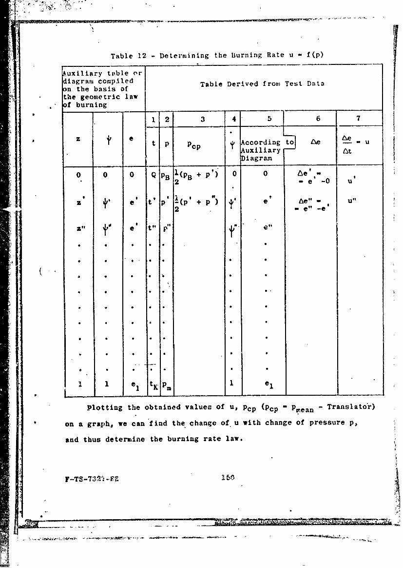
rate and of the given powder due to change of pressure p (Table 12).
F-TS-7327-RE 1 49 1- j'. . j.... . " .
Table 12 -Determining the B~urning Rate u f (p)
Auxiliary t&eble ordiagram4 compAled Table Derived frow Test Dataon the basis ofthe geometric lawofI burning_______ _____
1_ - 12 3 4 5__ 7
ze LePt p Pcp ccordingt Ae WU
Auxiliary ttDiag ram
0 0 0 Q BIP 0' 0 Ae i- 9
2 -e0
z t" e t p -(P, +p) e he" Ul2 mef -e'
We ji eq .l -9 ft
e ti PM el0
Plttn th obaie vaue of 0tpp(C ranTasa
onagahw a idtecageo( ihcag fpesr ,an thu *een the bunn raelw
F-T0-021* 0 100
1I
The for,.ula. ,ost often used for determining the burning rate
are the following.
a) Vieille's formula (exponential equation)
u - ApV,
where A and V depend on the nature of the powder, and, in particular,
v may be equal to unity.
The smaller the value ofy , the less sqnsitive is the powder to
pressure changes.
For smokeless powders Vieille used V - 2/3, and for ordinary
black powders , - 1/2. Our tests with slowly burning black powders
for a time fuze gave the value of "- 1/5.
G.A. Zabudsky used V- 0.93 for pyroxyline powders. Some authors
use ) - 1 for cordites and V - 1.07 for ballistite.
b) Binomial formula
u -a + bp.
it was'first used by Prof. S.P. Vukolov .(1891-1897) in the Naval
Technical Laboratory, and then by .olf (1903) and Prof. I.P. Grave
(1904). Muiraur employed this formula considerably later (1930-1935).
In his thesis (1904) I.P. Grav6 Z-14_J compared formula u - ApP
with formula u - ap + b by analyzing a large number of bomb tests
conducteI by himself and others and arrived at the following conclusion:
"Both fo ,uiulas can be considered equally valid for expressing the
law gove r ing the change of burning rate under varying pressure,
because t e mean errors obtained with the use of these formulas are
Y-TS-7327- IE 151
-.,. ~-
generally the same, and both formulas give practically identical
results."
This deduction whlch appears strange at first glance, namely,
that a parabola (semicubical) and a straight line not passing through
'the origin give identically accurate results, can be explained as
follows.
The first tests in bombs .since the year 1880 were conducted with
the use of cylindrical crushers which do not permit recording press'ures
below 300-400 kg/cm 2 (fig. 38). The test data (points) are usually
scattered to a certain extent and do not lie on a definite line. As
a result, some of the investigators drew a parabola u - Apo through
these points, and others drew a straight line u - ap + b which does
not pass through the origin of the coordinates (curve 2).
The conclusion arrived at by Prof. Grave' confirms the fact that
( both lines pass sufficiently close to the points plotted on the
2basis of tests at pressures exceeding 400 kg/cm
The relationship u - f(p) could not be obtained experimentally at
low pressures .( - 400 kg/cm2 ) at that time, and the question of the
true relationship continued to remain open.
c)Formula u - Ap...
Charbonier (1908) first accepted the burning rate law in its
general form u - Apos and then, on the basis of his own analysis of
test curves p, t obtained in bomb tests arrived at the conclusion
that for French strip-type B powders Ycan be taken equal to o - 1.
F-TS-7327-RE 152
47 j~..u---'--'---'I
j i= !:Ij:i _ -.. .. . . . . . . . . . .
Thii law was accepted also 15y our Prof. N.F. Drozdov in hi's
thesis /-15 "7 in the year 1910.
In 1913, Schmitz burned tubular po~ders in a large Krupp bomb,
using an elastic bar with an optical method of recording pressures
inste s of a crusher. He succeeded in obtaining a full curve of the
pressure increase in the bomb from the start to the end of powder
burning. In order to evaluate the accuracy of either burning rate
law, he introduced a new criterion, and proved by means of an attual
test the justness of the burning rate law in the form u - Ap.
Fig. 38 - Dependence of Burning Rate on Pressure.
The criterion determining the justness of this law confirmed
by experiment is presented below.
We shall assume that the following law holds true:
u- Ap; 0since the burning rate is a ratio between the increment of the
burned thickness de and the corresponding time element dt, i.e.,
de
t h e n - -
de/dt - Ap;
de - Ap-dt.
F-TS-7327-RE 153
I ntegrtng-, we__get:
" ':" e t t"
dem e. A pdt or pdt "-, - --
a 0
Burning. terminates when thickness e is burned. The full time14 of burning will be tK, and we will have:
ii A pdt
0
wbence /
pdt el cont-(for the given powder).• A0
Magnitudes e and A characterize the dimensions and nature of
the powder and do not depend on .the con~d~jt-ins of loading.
It follows: that if the burning rate law u - Ap is correct,
the pressure impulse of the powder gases depends only on the burned
thickness of the powder* on the burning rate coefficient, and on
the characteristic properties of the powder,, and does not depend on
the loading density
The full pressure imoulse during the full time of burbing equals
half of the thickness e1 of the burning layer divided by the burning
'rate coefficient A, and does not depend on the loading density.
F-TS-'7327-RE 154
GRAPHIC NOT REPRODUCIBLE
Fig. 39 - po t Curves for Different Loading Densities.
When conducting tests with tubular powder of one kind in a Krupp
bomb, with A varying from 0.12 to 0.26,, and upon measuring the area
under the pressure curves p - fsL), Schmitz had fouind that the areas
t K4pdt found by experiment are actually equal to one another, which
0finding confirms the validity of the u - Ap law.
Figure 39 shows the form and arrangem~ent of pA t curves.
The greater the loading density, the smaller is the burning time
and the higher is the gas pressure p, t curve.
Were the u -de/dt - ap + b law valid, then, after transformation,
we would bave:
do - apdt /r b-dt
and
5pdtm-e1 /a-0
Inasmuch as t K decreases when n.increases, then, according to
the u, - ap + b law, the full gas pressure ir.pulse should become
greater with Increase of loading density.
When applying the u ApI law, where 10 I an analogous
F-TS-7327-RE' 155
deduction Is obtained.
tKSchmitz's tests have shown that pdt does not dtpend on the
0A loading densityo which served to prove the validity of the u - Ap
"* '= law. ." -. .
'These tests had attracted the attention of many investigators
u- and provided data for the verification of theoretical deduction and
lnvestigations. The latter include the work of Muiraur on the study
of the burning rates of colloidal powders (1927-1928) and of
calculating the amount of heat transferred to. the walls during burning
of powder (1924-1925).
U.S. Serebriakov's tests with pyroxyline and nitroglycerine powders
confirmed the validity of the u - Ap law. These tests will be
discussed in greater detail in section III dealing with the physical
law of burning. •
Thus it may be assued that the value of u as the rate of
penetration of the burning reaction inside the grain is directly
-proportional to preskure, i.e., it is expressed by the formula:
u - Ap.
Here A can be express d as the ratio between the burning rate at
p - I (weshall desig ate .it by u1 ) and the magnitude of this pressure
• p-i: •
A- ul/1
(the subscript "1" iadi ates that this burning rate refers to pressure
p -i ).
P(
F-TS-7327-RE 156
This formula can be rewritten thus: L
u -u 1 * 2 up1 1
when p " 1 u - u1*
The dimensionality of the value of u can be seen from the
equality
u dm kg Ip sec dm 2
Ii.e., this represents the rate referred to unit pressure.
Similarly to powder energy f and covolume a, the magnitude uI
constitutes a fundamental ballistic characteristic of powder and,
similarly to I and a, depends on the physical and chemical properties
of the powder.
The value of u for pyroxyline powders varies from 0.0000060 to
0.0000090 dm/sec : kg/dm2 . The thicker the powder, the greater is
the content of volatiles and the slower is the burning of the powder.
The higher the nitrogen content in pyroxyline, the more rapid is
the burning. In nitroglycerine powders uI depends in the main on the
nitroglycerine content itself, and the greater its content the more
rapid is the burning. The admixture of dinitro-derivatives in
powders in a nonvolatile solvent usually reduces the burning rate.
Varying of the conteut of volatiles by +1% lowers the burning
rate of pyroxyline powders by 10-12%.
The following empirical formula for determining the burning
rate of pyroxyline powders, introduced for the first time by
F-TS-7327-RE 157
.~.*4 4 * *,. .,~ *
- - -.- ~- - --- .p
IN-.?~ Drozdov /.162 in our country, appears in American liter~iture:
-4 0o .0025E
* ( -48 (180 -,to) + 2561h + 909.5h'
where C - 9,4O0 (N -6.37) -powder energy in kg-rn/kg;
h.- content of volatile substtnces in %,removed, by six hours- *of drying (moisture);
h ik conltent of residual sovn n ntrevovedafesihours of drying; sleti o fe i
X --nitrogen content in*%
This formula clearly shows the effect of various individual
factors-on the burning rate, but does not give sufficient satisfactory
results as regards our own domestic powders.
-the following formula is better adopted to our pyroxyline powders
(1 - and is more convenient for performing the necessary calculations:
- 0.175(N -63)ma kg
0.42C - to) + 3h + h' sec m0.04(2
0.175 1 0-4(N -6.37) dm kg
0.04(220 - to) + 3h + hsec IM2
j.where 220 is4 the ignition temperature of 'the powder;
S 700,000(N- 6.37 kg-dm/kt;).
* F-TS-7327-RE 158
o.°
Letin assuied o.l the basis of the kiunetic theory of gases that
the bur:iing of powder is a process in which the powder v,oleculis
are split by the impact of gas molecules, aud offers the follouiiig
formula for determining u 1 : I2C2
/ C2
u - (i+ l)e P
pP
where g - acceleration of gravity;
6 mphysicl density of powder;
Cp - probable velocity of molecules of'gases formed in burningof powder;
C - velocity of active gas molecules, whose kinetic energy issufficient to split off at least one molecule when thesurface of the powder undergoes an impact.
c and .cI depend on the nature of the powder and of the gases
formed during its combustion.
Schmitz had conducted his tests at loading densities& of from
0.12 to 0.26. Later tests had shown that at very low loading densitiestK
(,0 .015) the integral pdt is a linearly decreasing function of0
time:
pdt S - Tt.
0
As was shown above, such a relationship is obtained under the
burning rate law u - ap + b.
F-TS -7327-RE 159
-/.-
E2
In the tests conducted by Y.E. Serebriakov /-5_ and A.I. Eokhaziov
it was shown that the integral pdt changes with increase of the0
time of burning only in the case of powders of considerable thickness
( ('2e l > 0.5); ia the.case of very thiL powders, the full impulse, even
-at low loading densities, does not depend on the loading density.
This shows •that the speed of the procesa governing the heating of the
entire powder mass is of importance, and that the increase of the
powder temperature increases the burning rate u and reduces the value
of the integral
tK
3 pt el/U1 9
0
In order to determine the effect of heating on thc burning rate
of powder under a given constant pressure, tests were conducted with
powder strips burned at different temperatures in open air. It was
found that the time of burning of a strip of a given length varies
from 14.1 seconds at t - 15 0 C to 9.4 seconds at t - 500 C, and hence
the rate of burning increases 1 1/2 times. The integral Ipdt - pa tK
was reduced in the same proportion, where pa is atmospheric pressure.
The effect of heating on the burning rate of powder can be
confirmed by the following tests.
If several charges of the same density are burned in succession
in a bomb without cooling, the latter becomes quite hot. The powder
inside the bomb becomes heated also, because the time between charging
.and the end of burning is considerable (several minutes). The value
of the integral becomes smaller with each successive test, which
F-TS-7327-RE 160
~2 _ __ ___ _
IT
condition points at an increasing rate of burning u1 for the same
powder thickness.
Thebe tests permit tne conclusion that the reduction. of the
integral IK with decrease of L for thick powders when A < 0.10 is
the result of heating of the powder mass under the condition of
relatively slow burning, whereby the degree of heating and hence the
increase in the value of u, is the greater, the smaller the value of
Z , i.e., the slower is the burning of the powder at low pressures.
Inasmuch as the integral of IK decreases with the decrease of tL,
the above will be theoretically valid if the burning rate laws u - Ap
and u - ap + b are adhered to. Tests conducted by M.E. Serebriakov
(1932) with powders with hard solvents showed that at pressures
Pm> 1000 kg/cm 2 the linear law u - Ap can be applied to determine
the burning rate, and that at pressures pm < 1000 kg/cm 2 the law0.82
expressed by the forruula u - Alp will apply.
In analyzing later tests conducted by Prof. Yu. A. Pobedonostsev
in bombs with nozzles at very low pressures (5 to 250 atm), Prof.
Ya.M. Shapiro arrived at the relationship u - 0.37 p0.7 which,
seemingly, is contradictory to the relationship u - Ap.
Actually, as was shown above, the decrease of the integral pdt
at small values of & can be explained also when applying the u -ulp
law by t.he increase of the burning rate uI due to heating of the
powder. This explanation s founded on the theory of Prof. Ya.B.
Zeldovich mentioned earlie'.
In any case a mcre accurate evaluation of either expression for
the burning rate law requir s further investigations (see Section I1).
F-TS-7327 -RE 161
41
Inasinuch as powders' i: gun barrels burn unde~r high presues
and udrhigh laigdniistefloigbrigr~eIwna
be considered valid for such pow,4ers:t
-'U umulpe
Going back to the formula for expressing the rate of gas form~ation, Iwe can now write it as follows:
d- S SuIp (31)
or
lS P-s(32)dt e1 Sl IK
2 K
whelre -and Sdepend on the geometry of the powder;1
'.u-As the burning rate of powder when p m1; it characterizesI~-the-nature of the powder and the degree to which it is heated;
p is the pressure at which the powder is burned; it characterizesthe influence of the surroiinding medium on the powder anddepends onA, f,, .,4.
CHAPTER VI - PIESSURE VARIATION AS A 'FUNCTION OF TIME
We havt derived above the following formulas: a) a formula for
' determining the rate ~of gas formation
I!Idt A1 5 el A
F,-TS-7327-RE 162
* Room
and b) the general pyrostatics'for-raila which lakes the igniter into
account.
4-, f, /1 P Pip + ., (34)
.where A 6. a is the relative free space in
-1 0.the bomb in which the powder is burned.
It is necessary to determine the dependence of the pressure change
on time when the powder is burned in a constant volume, i.e., to give
an analytical expression for the relationship between p -f(t)
dp/it and the full time of burning tK.
Differentiating equation (34) with respect to t, we get after
simple transformations:A + A) adp ( dy fA d
dt 2dt (1 at.) 2dt
1 - -is the value of A+ at the start of burning;
1 - aA the same'at the end of burning,
A > -A -1 n
It may be assumed with sufficient accuracy for practical purposes
that when 'cp 1/2
F-TS-7327-RE 163
FI -/ " , -.. c. -.-----
-,. K , - ___,___ 1.
- A2
Then,.making use of the relation (33), we get:
dp. fA d+. fA ul~L )E - :.. . .. sp. (35): ,dt' I -aA dt 1 a4. •l
In obrder to simplify further derivations, we shall consider a
*pwder whose, surface area changes little *hen burned, so that it may
'be* assumed that 6 " -Gc" const.cpA To surh powders belong the tube and the strip, for which the
binomial relationship j-bez(l +*Az) is valid, whereby for the end
Of burning (z = 1, I1)
IC 1 - )(l +X);
• " I+1+2
cp - 2
Therefore
xdc- it (1 + ) - i,
and for tubular or (to a lesser degree) strip powder
dp f ul 11 - PBd 6p - --lp. p (36)
4 dt/ I a eI I.
F-TS-1327-RE 164
We shall introduce the deb1g9:4L1on
el 1 -K
tm - " -secj; (37)u fI pm PB
dp _ P (38)
dt r
Upon separating the variables:
dp. dt
P 13
Integrating, we get
p t
dP I" dt o nP . tPdt or
PB 0
whence on the one hand
t 2.303rlog PB "(39)PB
and for the end of burning
t 2.303t log (40)
F-TS-7327-RE.
onl the other hand
t t
P e or p p~e ,(41)
and, or the end of burning
-pm pe .(42)
'Thus, all the required relationships are derived:
t 2.303:rl::og ;
dp _Pm1.- PB fA u1
dt IX m e, .
IK ellc1- - - secj7.
The magnitude 'r ______ constitutes the burning time-. ~p U( 3 PB) umn
of the powder if it burned at constant pressure pm Btrogot(.The full time of burning at a given loading density is proportional
to v and lgp./P8 , in other words, it is directly proportional to the
r-TS-7327-RE . 166
thickness of the poAder as;d irs.] proportional to the etwrg) of the
powder f and rate of burning ul, a.d .ecreases with the increase of
f&and P., (since the valuc of p1 in th#- deno,.iuator of r is more
effective than in the nu, erator tnder the logarithm); it also decreases
with the increase of the igniter pressure p.,
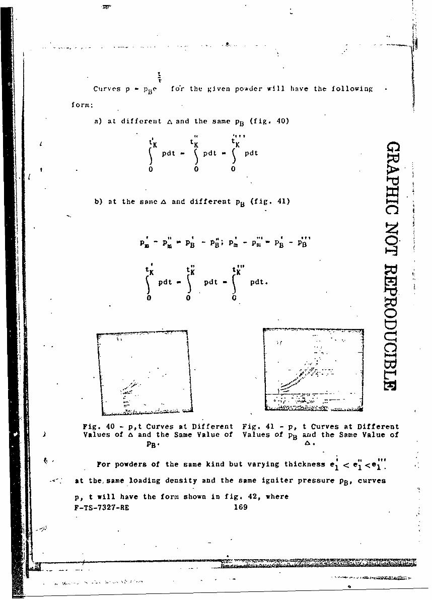
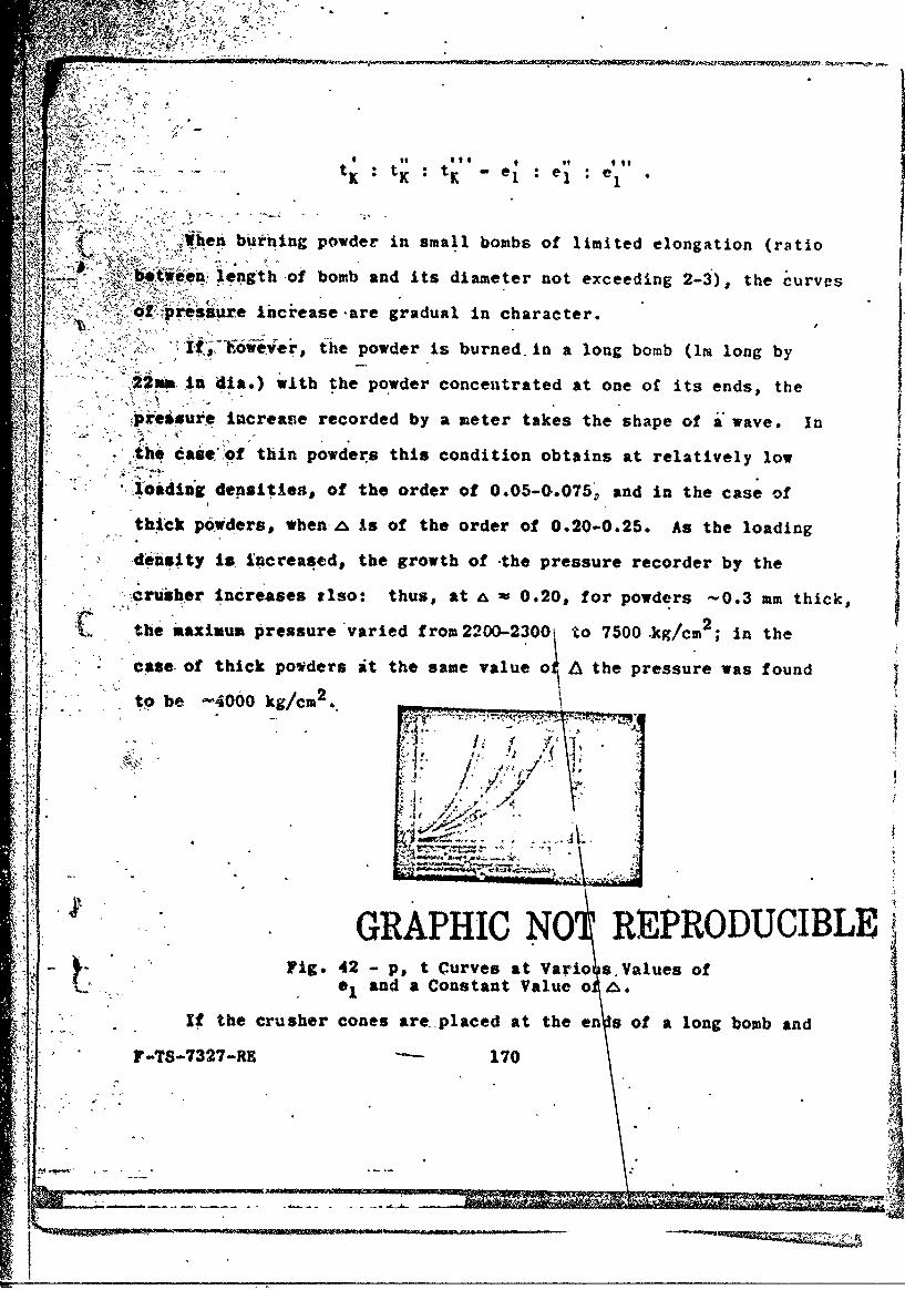
For tubular powder the relation p - f(t) serves as a characteristic
curve, whose slope .ngle (dp/dt - tanc) must continuously increase
in proportion to the gas pressure during the entire combustion process,
the rate of increase being the higher, the greater are the values of
f, &, u1 and the smaller the powder thickness ei. At the end of
burning the slope angle must be maximum (see figs. 39-42).
We shall derive the relation for the powder gas pressure impulse
on the basis of formula (41)
t Tt V
pdt PB e dt PpBt e d
0 0 0
B) el P -PB (3
- pBT(e - 1) -c(.p - PB) ( 43m - (4)
For the end of burning p Pm and
tK
pdt-- . (44)U-
0
The derived formulas confirm the general laws. of powder burning
F-TS-7327-U. 167
and show that the pressures the titae tor c onlplete co,.bustion and theS /
rate of pressure increase depend on the ballistic characteristics and- density of loading. Thus, it is precisely the ballistic characteristics
* L -,u, Ul the shape and dimensions of the powder (x , G, el) and the J
-P' losding density 4 that can be used to control the magnitude and rate- of zpressure increase of the gases evolved during the burning of- .
S, powder in a constant volume and to regulate the phenomenon of powder
buining and gas formation.j Example. Determine the maximum pressure and time of burning of