45
02220 Distributed Systems: Computer Networking Basics Alessio Di Mauro ([email protected]) Xenofon Fafoutis ([email protected])
| Date post: | 27-Dec-2015 |
| Category: |
Documents |
| Upload: | clemence-harper |
| View: | 214 times |
| Download: | 0 times |
02220 Distributed Systems: Computer Networking Basics
Alessio Di Mauro ([email protected])Xenofon Fafoutis ([email protected])
Introduction 1-2
Chapter 1Introduction
Computer Networking: A Top Down Approach 6th edition Jim Kurose, Keith RossAddison-WesleyMarch 2012
All material copyright 1996-2012 J.F Kurose and K.W. Ross, All Rights Reserved

Introduction
What’s the Internet: “nuts and bolts” view
millions of connected computing devices:
hosts = end systems running network apps
communication links
fiber, copper, radio, satellite
Packet switches: forward packets (chunks of data)
routers and switches
wiredlinks
wirelesslinks
router
mobile network
global ISP
regional ISP
home network
institutional network
smartphone
PC
server
wirelesslaptop
1-3

Introduction
What’s a protocol?
human protocols: “what’s the time?” “I have a question” introductions
… specific msgs sent… specific actions
taken when msgs received, or other events
network protocols: machines rather
than humans all communication
activity in Internet governed by protocols
protocols define format, order of msgs sent and
received among network entities,
and actions taken on msg transmission,
receipt
1-4

Introduction
a human protocol and a computer network protocol:
Hi
Hi
Got thetime?
2:00
TCP connectionresponse
Get http://www.awl.com/kurose-ross
<file>time
TCP connectionrequest
What’s a protocol?
1-5

Introduction
A closer look at network structure:
network edge: hosts: clients and servers servers often in data centers
access networks, physical media: wired, wireless communication links
network core: interconnected routers
network of networks
mobile network
global ISP
regional ISP
home network
institutional network
1-6

Introduction
mesh of interconnected routers
packet-switching: hosts break application-layer messages into packets forward packets from
one router to the next, across links on path from source to destination
The network core
1-7
Introduction
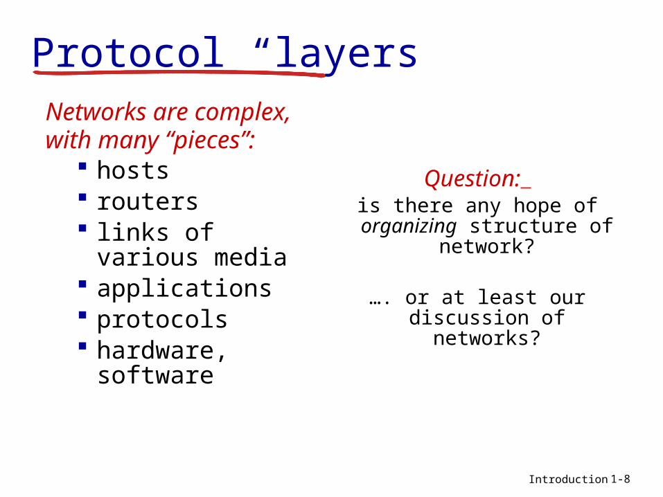
Protocol “layers”Networks are
complex,with many “pieces”:
hosts routers links of various
media applications protocols hardware,
software
Question: is there any hope of organizing structure of
network?
…. or at least our discussion of networks?
1-8

Introduction
Organization of air travel
a series of steps
ticket (purchase)
baggage (check)
gates (load)
runway takeoff
airplane routing
ticket (complain)
baggage (claim)
gates (unload)
runway landing
airplane routing
airplane routing
1-9
Introduction
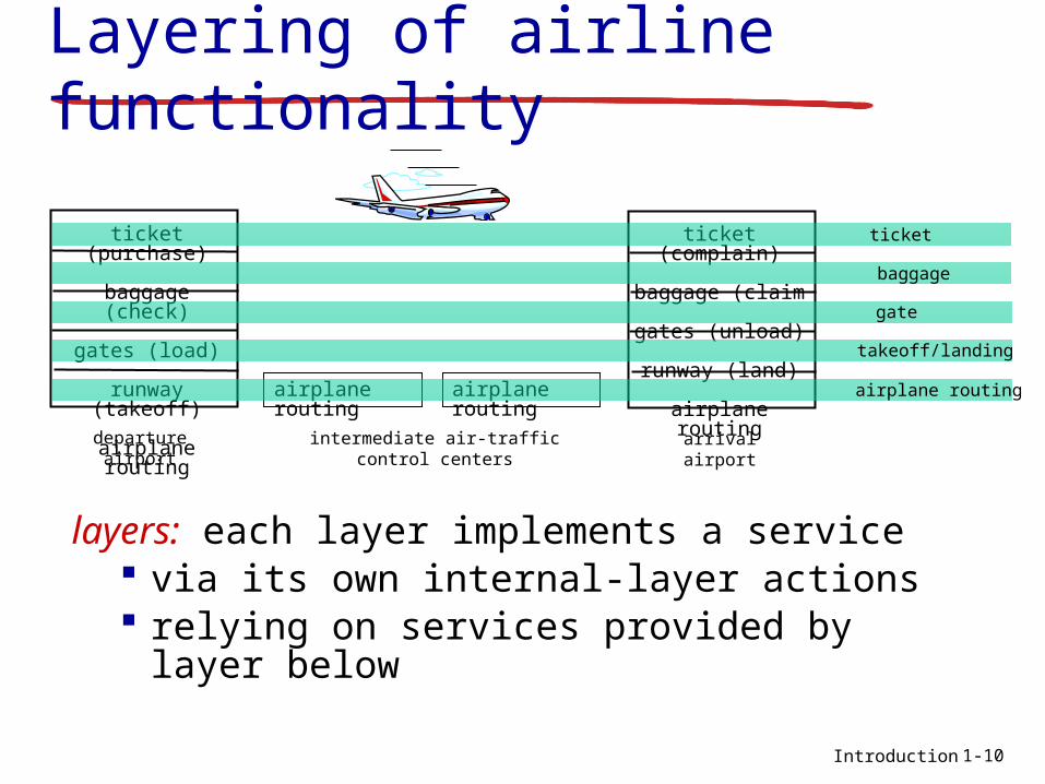
ticket (purchase)
baggage (check)
gates (load)
runway (takeoff)
airplane routing
departureairport
arrivalairport
intermediate air-trafficcontrol centers
airplane routing airplane routing
ticket (complain)
baggage (claim
gates (unload)
runway (land)
airplane routing
ticket
baggage
gate
takeoff/landing
airplane routing
Layering of airline functionality
layers: each layer implements a service via its own internal-layer actions relying on services provided by layer
below
1-10
Introduction
Why layering?dealing with complex systems: explicit structure allows identification,
relationship of complex system’s pieces layered reference model for discussion
modularization eases maintenance, updating of system change of implementation of layer’s service
transparent to rest of system e.g., change in gate procedure doesn’t
affect rest of system layering disadvantages?
1-11
Introduction
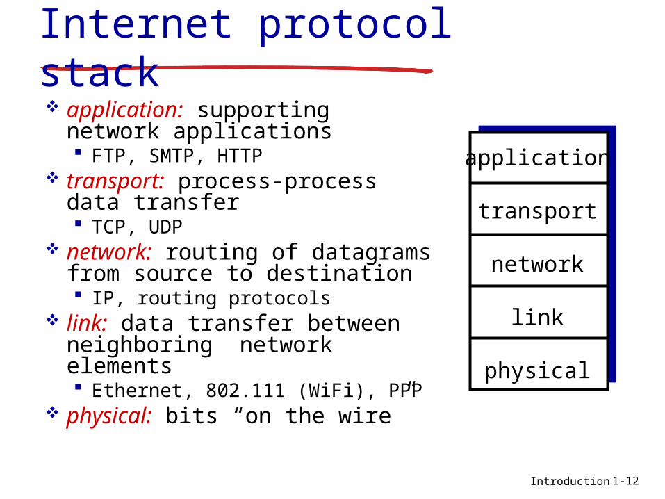
Internet protocol stack application: supporting
network applications FTP, SMTP, HTTP
transport: process-process data transfer TCP, UDP
network: routing of datagrams from source to destination IP, routing protocols
link: data transfer between neighboring network elements Ethernet, 802.111 (WiFi), PPP
physical: bits “on the wire”
application
transport
network
link
physical
1-12

Introduction
ISO/OSI reference model
presentation: allow applications to interpret meaning of data, e.g., encryption, compression, machine-specific conventions
session: synchronization, checkpointing, recovery of data exchange
Internet stack “missing” these layers! these services, if needed, must
be implemented in application needed?
application
presentation
session
transport
network
link
physical
1-13

Introduction
source
applicationtransportnetwork
linkphysical
HtHn M
segment Ht
datagram
destination
applicationtransportnetwork
linkphysical
HtHnHl M
HtHn M
Ht M
M
networklink
physical
linkphysical
HtHnHl M
HtHn M
HtHn M
HtHnHl M
router
switch
Encapsulationmessage M
Ht M
Hn
frame
1-14

Application Layer 2-15
Chapter 2Application Layer
Computer Networking: A Top Down Approach 6th edition Jim Kurose, Keith RossAddison-WesleyMarch 2012
All material copyright 1996-2012 J.F Kurose and K.W. Ross, All Rights Reserved
Application Layer 2-16
Some network apps e-mail web text messaging remote login P2P file sharing multi-user network
games streaming stored
video (YouTube, Hulu, Netflix)
voice over IP (e.g., Skype)
real-time video conferencing
social networking search … …

Application Layer 2-17
Creating a network appwrite programs that: run on (different) end
systems communicate over
network e.g., web server software
communicates with browser software
no need to write software for network-core devices
network-core devices do not run user applications
applications on end systems allows for rapid app development, propagation
applicationtransportnetworkdata linkphysical
applicationtransportnetworkdata linkphysical
applicationtransportnetworkdata linkphysical
Application Layer 2-18
Application architectures
possible structure of applications: client-server peer-to-peer (P2P)

Application Layer 2-19
Client-server architecture
server: always-on host permanent IP address data centers for scaling
clients: communicate with server may be intermittently
connected may have dynamic IP
addresses do not communicate
directly with each other
client/server
Application Layer 2-20
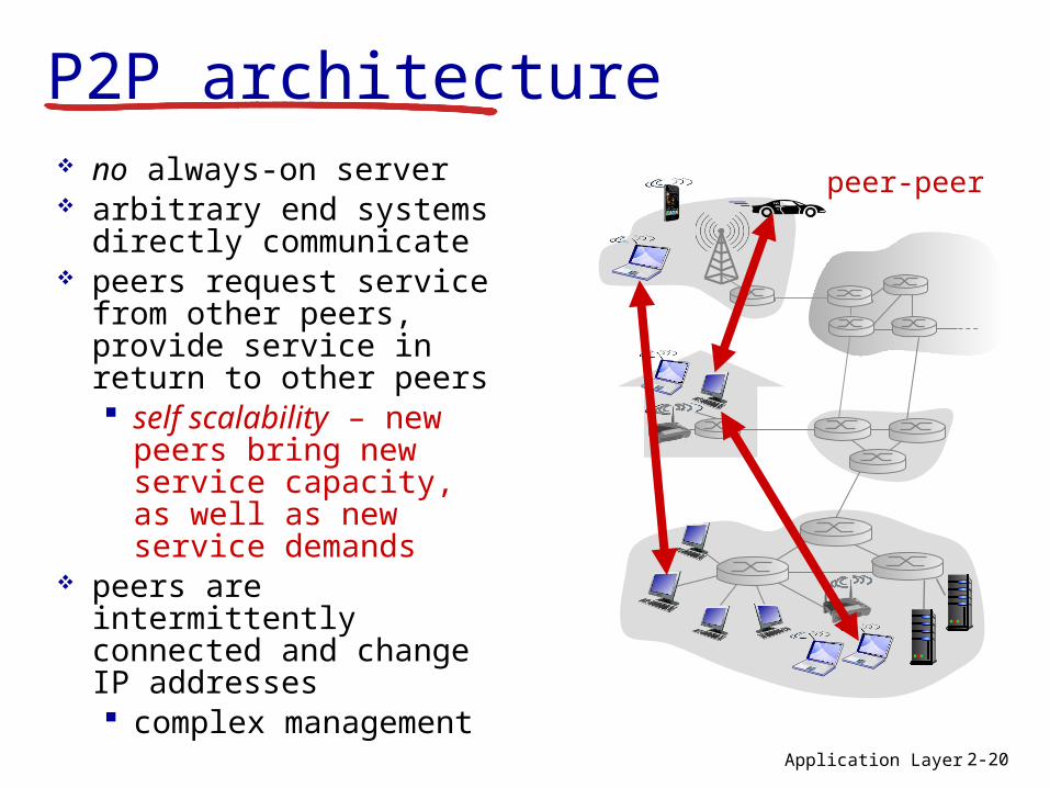
P2P architecture no always-on server arbitrary end systems
directly communicate peers request service
from other peers, provide service in return to other peers self scalability – new
peers bring new service capacity, as well as new service demands
peers are intermittently connected and change IP addresses complex
management
peer-peer

Application Layer 2-21
Processes communicating
process: program running within a host
within same host, two processes communicate using inter-process communication (defined by OS)
processes in different hosts communicate by exchanging messages
client process: process that initiates communication
server process: process that waits to be contacted
aside: applications with P2P architectures have client processes & server processes
clients, servers
Application Layer 2-22
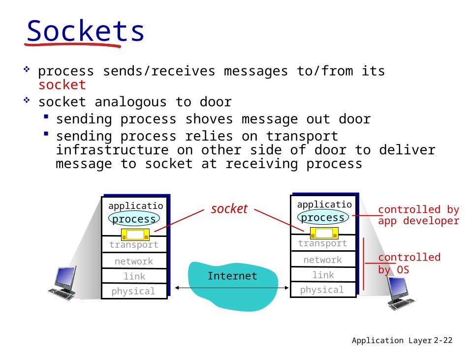
Sockets process sends/receives messages to/from its socket socket analogous to door
sending process shoves message out door sending process relies on transport infrastructure
on other side of door to deliver message to socket at receiving process
Internet
controlledby OS
controlled byapp developer
transport
application
physical
link
network
process
transport
application
physical
link
network
processsocket
Application Layer 2-23
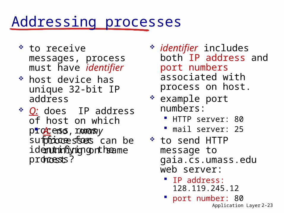
Addressing processes
to receive messages, process must have identifier
host device has unique 32-bit IP address
Q: does IP address of host on which process runs suffice for identifying the process?
identifier includes both IP address and port numbers associated with process on host.
example port numbers: HTTP server: 80 mail server: 25
to send HTTP message to gaia.cs.umass.edu web server: IP address:
128.119.245.12 port number: 80
A: no, many processes can be running on same host

Application Layer 2-24
App-layer protocol defines types of messages
exchanged, e.g., request,
response message syntax:
what fields in messages & how fields are delineated
message semantics meaning of
information in fields rules for when and how
processes send & respond to messages
open protocols: defined in RFCs allows for
interoperability e.g., HTTP, SMTPproprietary protocols: e.g., Skype
Application Layer 2-25
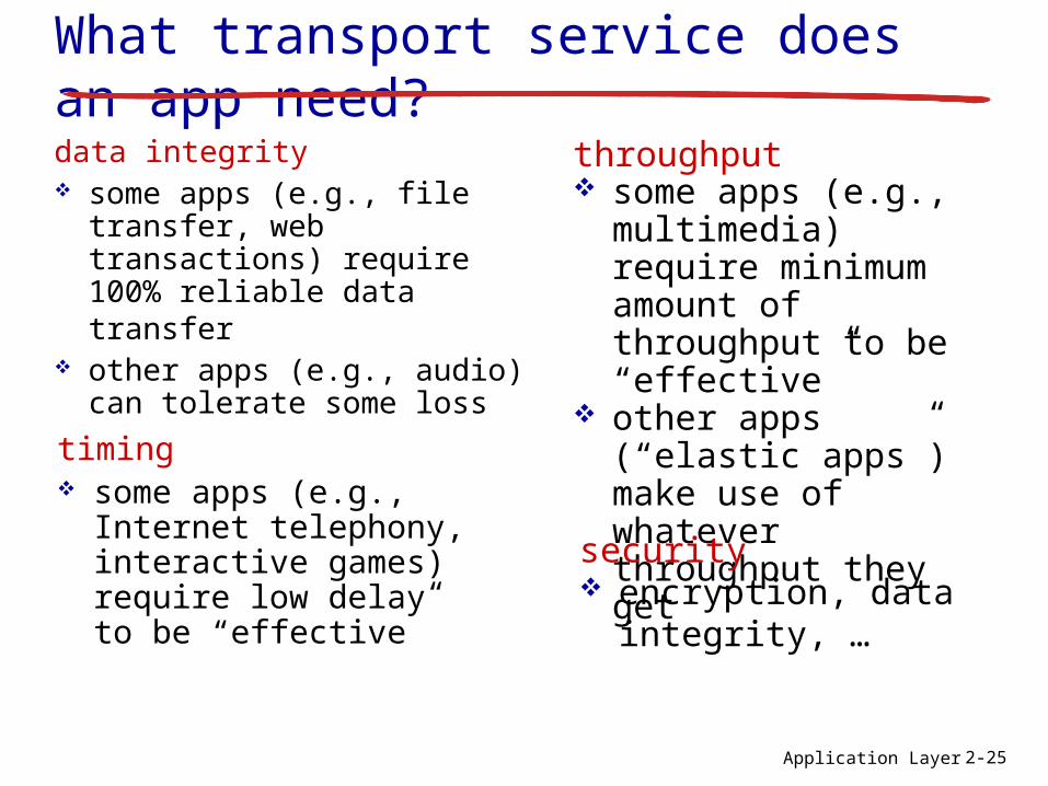
What transport service does an app need?data integrity some apps (e.g., file
transfer, web transactions) require 100% reliable data transfer
other apps (e.g., audio) can tolerate some losstiming
some apps (e.g., Internet telephony, interactive games) require low delay to be “effective”
throughput some apps (e.g.,
multimedia) require minimum amount of throughput to be “effective”
other apps (“elastic apps”) make use of whatever throughput they get
security encryption, data
integrity, …
Application Layer 2-26
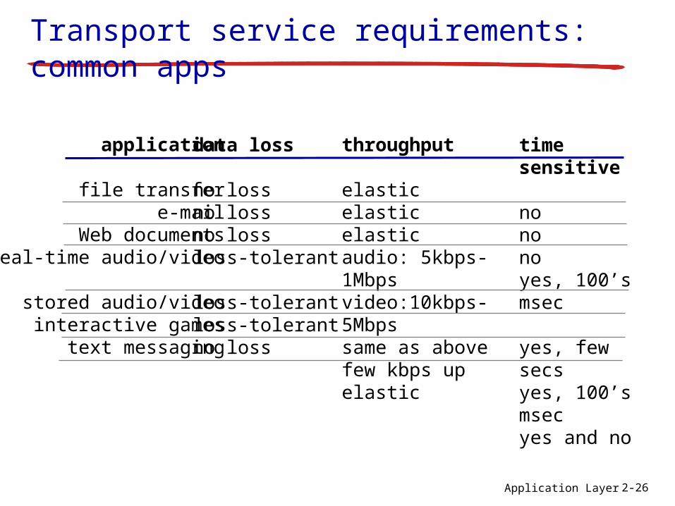
Transport service requirements: common apps
application
file transfere-mail
Web documentsreal-time audio/video
stored audio/videointeractive games
text messaging
data loss
no lossno lossno lossloss-tolerant
loss-tolerantloss-tolerantno loss
throughput
elasticelasticelasticaudio: 5kbps-1Mbpsvideo:10kbps-5Mbpssame as above few kbps upelastic
time sensitive
nononoyes, 100’s msec
yes, few secsyes, 100’s msecyes and no
Application Layer 2-27
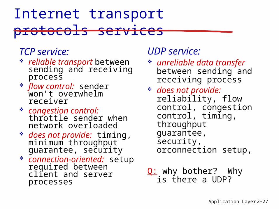
Internet transport protocols servicesTCP service: reliable transport
between sending and receiving process
flow control: sender won’t overwhelm receiver
congestion control: throttle sender when network overloaded
does not provide: timing, minimum throughput guarantee, security
connection-oriented: setup required between client and server processes
UDP service: unreliable data
transfer between sending and receiving process
does not provide: reliability, flow control, congestion control, timing, throughput guarantee, security, orconnection setup,
Q: why bother? Why is there a UDP?
Application Layer 2-28
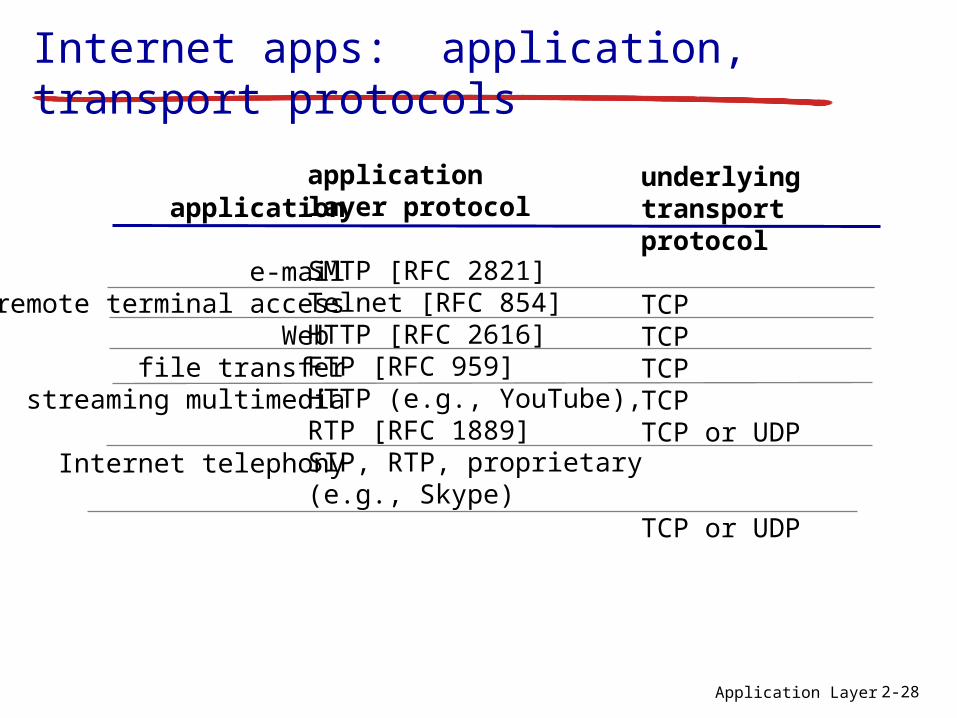
Internet apps: application, transport protocols
application
e-mailremote terminal access
Web file transfer
streaming multimedia
Internet telephony
applicationlayer protocol
SMTP [RFC 2821]Telnet [RFC 854]HTTP [RFC 2616]FTP [RFC 959]HTTP (e.g., YouTube), RTP [RFC 1889]SIP, RTP, proprietary(e.g., Skype)
underlyingtransport protocol
TCPTCPTCPTCPTCP or UDP
TCP or UDP
Transport Layer 3-29
Chapter 3Transport Layer
Computer Networking: A Top Down Approach 6th edition Jim Kurose, Keith RossAddison-WesleyMarch 2012
All material copyright 1996-2012 J.F Kurose and K.W. Ross, All Rights Reserved
Transport Layer 3-30
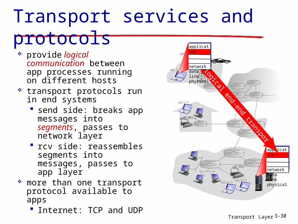
Transport services and protocols
provide logical communication between app processes running on different hosts
transport protocols run in end systems send side: breaks app
messages into segments, passes to network layer
rcv side: reassembles segments into messages, passes to app layer
more than one transport protocol available to apps Internet: TCP and UDP
applicationtransportnetworkdata linkphysical
logical end-end transport
applicationtransportnetworkdata linkphysical

Transport Layer 3-31
Transport vs. network layer network layer:
logical communication between hosts
transport layer: logical communication between processes relies on,
enhances, network layer services
12 kids in Ann’s house sending letters to 12 kids in Bill’s house:
hosts = houses processes = kids app messages =
letters in envelopes transport protocol =
Ann and Bill who demux to in-house siblings
network-layer protocol = postal service
household analogy:
Transport Layer 3-32
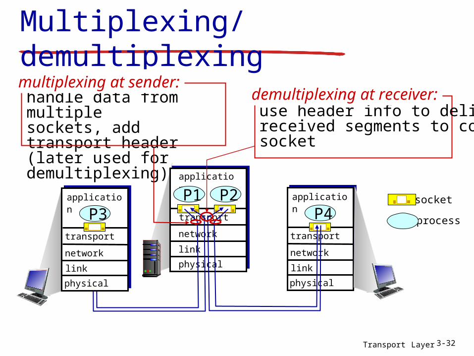
Multiplexing/demultiplexing
process
socket
use header info to deliverreceived segments to correct socket
demultiplexing at receiver:handle data from multiplesockets, add transport header (later used for demultiplexing)
multiplexing at sender:
transport
application
physical
link
network
P2P1
transport
application
physical
link
network
P4transport
application
physical
link
network
P3

Transport Layer 3-33
How demultiplexing works
host receives IP datagrams each datagram has source IP
address, destination IP address each datagram carries one
transport-layer segment each segment has source,
destination port number host uses IP addresses & port
numbers to direct segment to appropriate socket
source port # dest port #
32 bits
applicationdata (payload)
other header fields
TCP/UDP segment format

Transport Layer 3-34
Connectionless demultiplexing
recall: created socket has host-local port #:
DatagramSocket mySocket1 = new DatagramSocket(12534);
when host receives UDP segment: checks destination
port # in segment directs UDP segment
to socket with that port #
recall: when creating datagram to send into UDP socket, must specify
destination IP address destination port #IP datagrams with same dest. port #, but different source IP addresses and/or source port numbers will be directed to same socket at dest

Transport Layer 3-35
Connectionless demux: example
DatagramSocket serverSocket = new DatagramSocket
(6428);
transport
application
physical
link
network
P3transport
application
physical
link
network
P1
transport
application
physical
link
network
P4
DatagramSocket mySocket1 = new DatagramSocket (5775);
DatagramSocket mySocket2 = new DatagramSocket (9157);
source port: 9157dest port: 6428
source port: 6428dest port: 9157
source port: 6428dest port: 5775
source port: 5775dest port: 6428

Transport Layer 3-36
Connection-oriented demux
TCP socket identified by 4-tuple: source IP address source port number dest IP address dest port number
demux: receiver uses all four values to direct segment to appropriate socket
server host may support many simultaneous TCP sockets: each socket
identified by its own 4-tuple
web servers have different sockets for each connecting client
Transport Layer 3-37
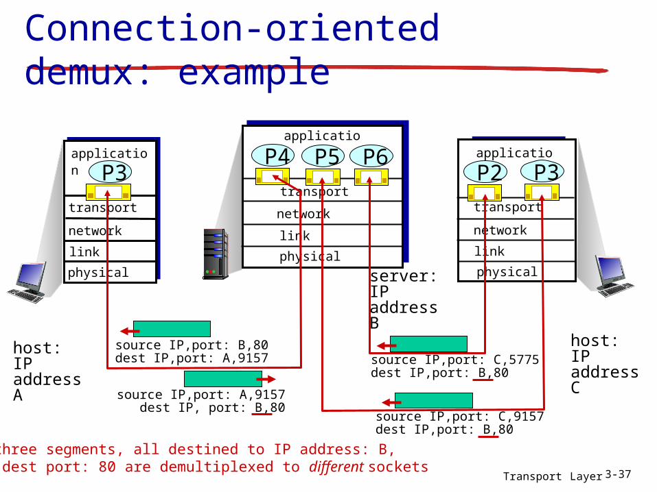
Connection-oriented demux: example
transport
application
physical
link
network
P3transport
application
physical
link
P4
transport
application
physical
link
network
P2
source IP,port: A,9157dest IP, port: B,80
source IP,port: B,80dest IP,port: A,9157
host: IP address A
host: IP address C
network
P6P5P3
source IP,port: C,5775dest IP,port: B,80
source IP,port: C,9157dest IP,port: B,80
three segments, all destined to IP address: B, dest port: 80 are demultiplexed to different sockets
server: IP address B
Transport Layer 3-38
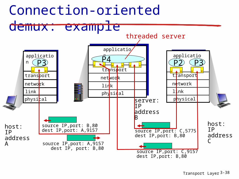
Connection-oriented demux: example
transport
application
physical
link
network
P3transport
application
physical
link
transport
application
physical
link
network
P2
source IP,port: A,9157dest IP, port: B,80
source IP,port: B,80dest IP,port: A,9157
host: IP address A
host: IP address C
server: IP address B
network
P3
source IP,port: C,5775dest IP,port: B,80
source IP,port: C,9157dest IP,port: B,80
P4
threaded server

Chapter 4Network Layer
Computer Networking: A Top Down Approach 6th edition Jim Kurose, Keith RossAddison-WesleyMarch 2012
All material copyright 1996-2012 J.F Kurose and K.W. Ross, All Rights Reserved
Network Layer 4-39

Network Layer 4-40
IP addressing: introduction
IP address: 32-bit identifier for host, router interface
interface: connection between host/router and physical link router’s typically have
multiple interfaces host typically has one
or two interfaces (e.g., wired Ethernet, wireless 802.11)
IP addresses associated with each interface
223.1.1.1
223.1.1.2
223.1.1.3
223.1.1.4 223.1.2.9
223.1.2.2
223.1.2.1
223.1.3.2223.1.3.1
223.1.3.27
223.1.1.1 = 11011111 00000001 00000001 00000001
223 1 11
Network Layer 4-41
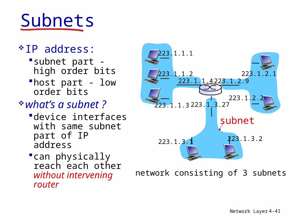
SubnetsIP address:
subnet part - high order bits
host part - low order bits
what’s a subnet ?device interfaces with same subnet part of IP address
can physically reach each other without intervening router
network consisting of 3 subnets
223.1.1.1
223.1.1.3
223.1.1.4 223.1.2.9
223.1.3.2223.1.3.1
subnet
223.1.1.2
223.1.3.27223.1.2.2
223.1.2.1

Network Layer 4-42
recipe to determine the
subnets, detach each interface from its host or router, creating islands of isolated networks
each isolated network is called a subnet
subnet mask: /24
Subnets223.1.1.0/24
223.1.2.0/24
223.1.3.0/24
223.1.1.1
223.1.1.3
223.1.1.4 223.1.2.9
223.1.3.2223.1.3.1
subnet
223.1.1.2
223.1.3.27223.1.2.2
223.1.2.1
Network Layer 4-43
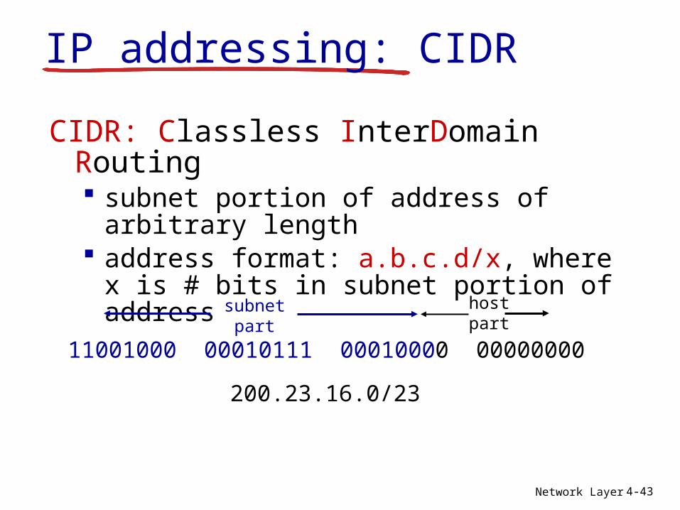
IP addressing: CIDR
CIDR: Classless InterDomain Routing subnet portion of address of arbitrary
length address format: a.b.c.d/x, where x is #
bits in subnet portion of address
11001000 00010111 00010000 00000000
subnetpart
hostpart
200.23.16.0/23

Network Layer 4-44
IP addresses: how to get one?Q: How does a host get IP address?
hard-coded by system admin in a file Windows: control-panel->network->configuration-
>tcp/ip->properties UNIX: /etc/rc.config
DHCP: Dynamic Host Configuration Protocol: dynamically get address from as server “plug-and-play”
Network Layer 4-45
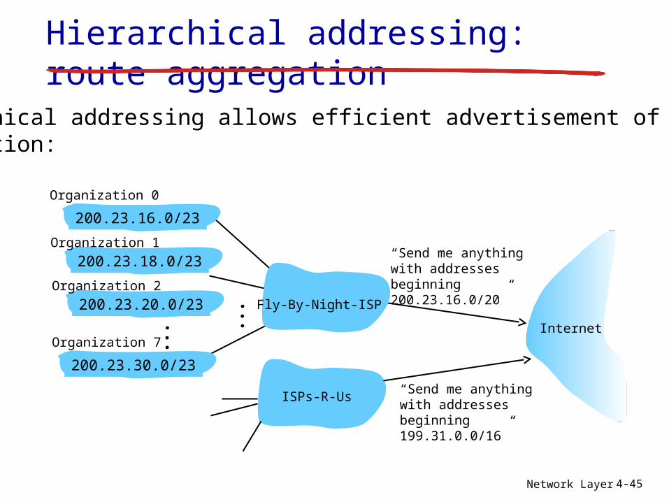
Hierarchical addressing: route aggregation
“Send me anythingwith addresses beginning 200.23.16.0/20”
200.23.16.0/23
200.23.18.0/23
200.23.30.0/23
Fly-By-Night-ISP
Organization 0
Organization 7Internet
Organization 1
ISPs-R-Us“Send me anythingwith addresses beginning 199.31.0.0/16”
200.23.20.0/23Organization 2
...
...
hierarchical addressing allows efficient advertisement of routing information:


![Canards in stiction: on solutions of a friction ... - DTU · Lyngby 2800, DK (ebos@dtu.dk,mobr@dtu.dk,krkri@dtu.dk). 1 arXiv:1703.08437v1 [math.DS] 24 Mar 2017. the discontinuity,](https://static.documents.pub/doc/80x56/613cff3c4c23507cb635bd60/canards-in-stiction-on-solutions-of-a-friction-dtu-lyngby-2800-dk-ebosdtudkmobrdtudkkrkridtudk.jpg)

![Xenofon“Fontas” Fafoutis · 2011-04-14 · Xenofon“Fontas” Fafoutis. 2 DTU Informatics, Technical University of Denmark Wireless Sensor Networks 14/04/2011 Sensors. ... [2-4]](https://static.documents.pub/doc/80x56/5e5f2da2fd7bcf75556e5b74/xenofonaoefontasa-2011-04-14-xenofonaoefontasa-fafoutis-2-dtu-informatics.jpg)


