60
ir33 platform ir33 ir33 power ir33 DIN powercompact powercompact small mastercella User manual
ir33 platform ir33 ir33 power ir33 DIN powercompact powercompact small mastercella
User manual


User manual
EN
GL
ISH
IMPORTANT WARNINGS
CAREL bases the development of its products on decades of experience in HVAC, on the continuous investments in technological innovations to products, procedures and strict quality processes with in-circuit and functional testing on 100% of its products, and on the most innovative production technology available on the market.CAREL and its subsidiaries nonetheless cannot guarantee that all the aspects of the product and the software included with the product respond to the requirements of the fi nal application, despite the product being developed according to start-of-the-art techniques. The customer (manufacturer, developer or installer of the fi nal equipment) accepts all liability and risk relating to the confi guration of the product in order to reach the expected results in relation to the specifi c fi nal installation and/or equipment. CAREL may, based on specifi c agreements, acts as a consultant for the positive commissioning of the fi nal unit/application, however in no case does it accept liability for the correct operation of the fi nal equipment/system.The CAREL product is a state-of-the-art product, whose operation is specifi ed in the technical documentation supplied with the product or can be downloaded, even prior to purchase, from the website www.carel.com.Each CAREL product, in relation to its advanced level of technology, requires setup/confi guration/programming/commissioning to be able to operate in the best possible way for the specifi c application. The failure to complete such operations, which are required/indicated in the user manual, may cause the fi nal product to malfunction; CAREL accepts no liability in such cases.Only qualifi ed personnel may install or carry out technical service on the product.The customer must only use the product in the manner described in the documentation relating to the product. In addition to observing any further warnings described in this manual, the following warnings must be heeded for all CAREL products:• Prevent the electronic circuits from getting wet. Rain, humidity and all types of liquids or condensate contain corrosive minerals that may damage the electronic circuits. In any case, the product should be used or stored in environments that comply with the temperature and humidity limits specifi ed in the manual.• Do not install the device in particularly hot environments. Too high temperatures may reduce the life of electronic devices, damage them and deform or melt the plastic parts. In any case, the product should be used or stored in environments that comply with the temperature and humidity limits specifi ed in the manual.• Do not attempt to open the device in any way other than described in the manual.• Do not drop, hit or shake the device, as the internal circuits and mechanisms may be irreparably damaged.• Do not use corrosive chemicals, solvents or aggressive detergents to clean the device.• Do not use the product for applications other than those specifi ed in the technical manual.
All of the above suggestions likewise apply to the controllers, serial boards, programming keys or any other accessory in the CAREL product portfolio.
CAREL adopts a policy of continual development. Consequently, CAREL reserves the right to make changes and improvements to any product described in this document without prior warning.
The technical specifi cations shown in the manual may be changed without prior warning.
The liability of CAREL in relation to its products is specifi ed in the CAREL general contract conditions, available on the website www.carel.com and/or by specifi c agreements with customers; specifi cally, to the extent where allowed by applicable legislation, in no case will CAREL, its employees or subsidiaries be liable for any lost earnings or sales, losses of data and information, costs of replacement goods or services, damage to things or people, downtime or any direct, indirect, incidental, actual, punitive, exemplary, special or consequential damage of any kind whatsoever, whether contractual, extra-contractual or due to negligence, or any other liabilities deriving from the installation, use or impossibility to use the product, even if CAREL or its subsidiaries are warned of the possibility of such damage.
Disposing of the parts of the controller:The controller is made up of metal and plastic parts and a lithium battery. All these parts must be disposed of separately in compliance with the local standards in force on waste disposal.
5
EN
GL
ISH
ir33 +030220440 - rel. 2.0 - 01.05.2006
Content
1. INTRODUCTION 7
1.1 Main features ..........................................................................................................................................72.1 Display .....................................................................................................................................................9
2. USER INTERFACE 9
2.2 ir33,ir33 power and ir33DIN keypad ................................................................................................102.3 powercompact, powercompact small and MasterCella keypad ................................................11
3. INSTALLATION 12
4. PROGRAMMING THE INSTRUMENTS 13
4.1 Modifying the parameters ...................................................................................................................134.2 Storing the new values assigned to the parameters .....................................................................134.3 Classifi cation of the parameters .........................................................................................................134.5 Setting the set point ..............................................................................................................................144.6 Alarms with manual reset ....................................................................................................................144.7 Procedure for setting the default parameter values ......................................................................144.8 Semi-automatic serial address assignment procedure .................................................................145.1 Parameter copying key .........................................................................................................................15
5. ACCESSORIES 15
5.2 Remote control ......................................................................................................................................165.3 RS485 serial interface ...........................................................................................................................175.4 Programming kit ...................................................................................................................................175.5 Transformers (ir33, power, DIN) .......................................................................................................175.6 RS485 serial board (DIN) ....................................................................................................................175.7 RS485 serial board (MasterCella) ......................................................................................................175.8 Door interlock (MasterCella) ..............................................................................................................175.9 Terminals (MasterCella) .......................................................................................................................185.10 Repeater display interface option ....................................................................................................185.11 IR00R*0000 display terminal ............................................................................................................185.12 PST00VR100 display terminal (powercompact) ...........................................................................185.13 Optional interface-repeater display connection cable ................................................................18
6. DESCRIPTION OF THE FUNCTIONS 19
6.1 Models .....................................................................................................................................................196.2 Testing the display and keypad on start-up ....................................................................................196.3 Switching the controller ON and OFF ..............................................................................................206.5 Light management ................................................................................................................................216.6 Defrost .....................................................................................................................................................216.7 New defrost activation modes ...........................................................................................................246.8 Pump down and low pressure ...........................................................................................................266.9 Continuous cycle ...................................................................................................................................266.10 High condensing temperature alarm ..............................................................................................286.11 Control with dead band .....................................................................................................................296.12 Control with second step ...................................................................................................................306.13 Anti-sweat heater function .................................................................................................................316.14 Antifreeze alarm ...................................................................................................................................316.15 Special functions for the management of multiplexed cabinets (mpx) ..................................326.16 HACCP (Hazard Analysis and Critical Control Point) ...................................................................33

EN
GL
ISH
7. DESCRIPTION OF THE OPERATING PARAMETERS 34
7.1 Temperature probe management parameters ................................................................................347.2 Temperature control parameters ........................................................................................................367.3 Compressor management parameters .............................................................................................387.4 Defrost management parameters ......................................................................................................407.5 Alarm management parameters ........................................................................................................437.6 Fan management parameters .............................................................................................................507.7 General confi guration parameters .....................................................................................................517.8 HACCP alarm management parameters ..........................................................................................547.9 RTC and timed defrost management parameters ..........................................................................557.10 Summary table of operating parameters ........................................................................................56
8. ALARMS AND SIGNALS 58
8.1 Summary table of alarms and signals: display, buzzer and relay ...............................................588.2 Table of alarms and signals: functions enabled/disabled ............................................................59
7
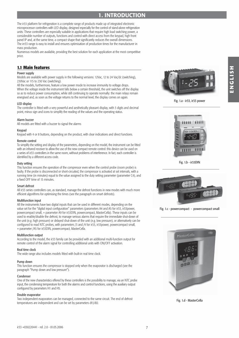
Fig. 1.b - ir33DIN
Fig. 1.c - powercompact - powercompact small
Fig. 1.a - ir33, ir33 power
Fig. 1.d - MasterCella
EN
GL
ISH
ir33 +030220441 - rel. 2.0 - 01.05.2006
1. INTRODUCTIONThe ir33 platform for refrigeration is a complete range of products made up of integrated electronic microprocessor controllers with LED display, designed especially for the control of stand-alone refrigeration units: These controllers are especially suitable in applications that require high load switching power, a considerable number of outputs, functions and control with direct access from the keypad, high front panel IP and, at the same time, a compact shape that signifi cantly reduces the overall dimensions. The irr33 range is easy to install and ensures optimisation of production times for the manufacturer in mass production.Numerous models are available, providing the best solution for each application at the most competitive price.
1.1 Main featuresPower supplyModels are available with power supply in the following versions: 12Vac, 12 to 24 Vac/dc (switching), 230Vac or 115 to 230 Vac (switching).All the models, furthermore, feature a low power mode to increase immunity to voltage drops.When the voltage inside the instrument falls below a certain threshold, the unit switches off the display so as to reduce power consumption, while still continuing to operate normally: the main relays remain energised and, as soon as the voltage returns to the normal level, the display comes on again.
LED displayThe controller is fitted with a very powerful and aesthetically pleasant display, with 3 digits and decimal point, minus sign and icons to simplify the reading of the values and the operating status.
Alarm buzzerAll models are fitted with a buzzer to signal the alarms
KeypadKeypad with 4 or 8 buttons, depending on the product, with clear indications and direct functions.
Remote controlTo simplify the setting and display of the parameters, depending on the model, the instrument can be fi tted with an infrared receiver to allow the use of the new compact remote control: this device can be used on a series of ir33 controllers in the same room, without problems of interference. In fact, each controller is identifi ed by a different access code.
Duty settingThis function ensures the operation of the compressor even when the control probe (room probe) is faulty. If the probe is disconnected or short-circuited, the compressor is activated at set intervals, with a running time (in minutes) equal to the value assigned to the duty setting parameter (parameter C4), and a fi xed OFF time of 15 minutes.
Smart defrostAll ir33 series controllers can, as standard, manage the defrost functions in new modes with much more effi cient algorithms for optimising the times (see the paragraph on smart defrosts).
Multifunction inputAll the instruments have two digital inputs that can be used in different modes, depending on the value set for the “digital input confi guration” parameters (parameters A4 and A5 for ir33, ir33power, powercompact small, + parameter A9 for ir33DIN, powercompact, MasterCella). These inputs can be used to enable/disable the defrost, to manage serious alarms that require the immediate shut-down of the unit (e.g. high pressure) or delayed shut-down of the unit (e.g. low pressure), or alternatively can be confi gured to read NTC probes, with parameters /3 and /4 for ir33, ir33power, powercompact small, + parameter /A5 for ir33DIN, powercompact, MasterCella.
Multifunction outputAccording to the model, the ir33 family can be provided with an additional multi-function output for remote control of the alarm signal for controlling additional units with ON/OFF activation.
Real time clockThe wide range also includes models fi tted with built-in real time clock.
Pump downThis function ensures the compressor is stopped only when the evaporator is discharged (see the paragraph “Pump down and low pressure”).
CondenserOne of the new characteristics offered by these controllers is the possibility to manage, via an NTC probe input, the condensing temperature for both the alarms and control functions, using the auxiliary output confi gured by parameters H1 and H5.
Double evaporatorTwo independent evaporators can be managed, connected to the same circuit. The end of defrost temperatures are independent and can be set by parameters dt1/dt2.
8
EN
GL
ISH
ir33 +030220441 - rel. 2.0 - 01.05.2006
HACCPThis function, increasingly required in the refrigeration market, is included as standard on all models with clock. This allows the monitoring of critical points by measuring and recording the temperatures in the event of high temperature alarms or power failures.Up to 3 high temperature alarms and 3 alarms corresponding to power failures can be saved.
Light managementThe ir33 platform has been enhanced by the introduction of the function for managing the light when the door opens, set by parameter.
Keypad protectionThe keypad and the remote control can be disabled to avoid tampering by unauthorised persons, above all in the event when the controller is installed in an area open to the public.
Continuous cycleThe “continuous cycle” function ensures the operation of the compressor for the time set by the corresponding parameter. This function is useful when a rapid reduction in the temperature is required.
Serial connectionThe entire range has an RS485 serial port for network connection to supervisor or telemaintenance systems using a shielded twisted pair cable.
Index of protectionThe gasket inside the front panel and the material used to make the keypad guarantee IP65 protection for the controller on the front panel.
InstallationThe controllers are mounted using the screws at the front, or alternatively using two quick-fi t side brac-kets, with compact dimensions, made from plastic.
In-circuit testingThe ir33 platform controllers are made using the most advanced SMD technology. All the controllers undergo “IN-CIRCUIT TESTING” to check electrical operation of all components.
NTC probeThe controllers can manage two types of NTC probes (see parameter “/P”): standard version –50T90°C (NTC0*HP*) or alternatively the model for high temperatures, up to 150°C (enhanced NTC –40T150°C).
Watch dogThis feature prevents the microprocessor from losing control over the unit even in the presence of considerable electromagnetic disturbance. In the event of abnormal operation, the watchdog function re-establishes the initial operating status. Not all the competitors fi t their products with this safety feature.
Electromagnetic compatibility The ir33 platform is compliant with EU standards on electromagnetic compatibility. The quality and the safety of the ir33 controllers are ensured by the CAREL ISO 9001 certifi ed design and production system and by the CE mark on the product.
Network functionsThe controllers feature management of multiplexed defrosts, remote alarm signals and the downloading of the parameters via the local network.
Parameter selectionSelection of the parameters on the display simplifi ed by the use of icons or with the standard Carel procedure.
Confi guration of the digital inputsThe digital inputs can be confi gured and used as NTC probe inputs, by simply setting a parameter.
ConnectorsModels fi tted with spade connectors or fi xed screw terminals.
Options• programming key;• RS485 serial interface can be added at any time;• optional repeater display for models with switching power supply.For further information, see the chapter on “Accessories”.
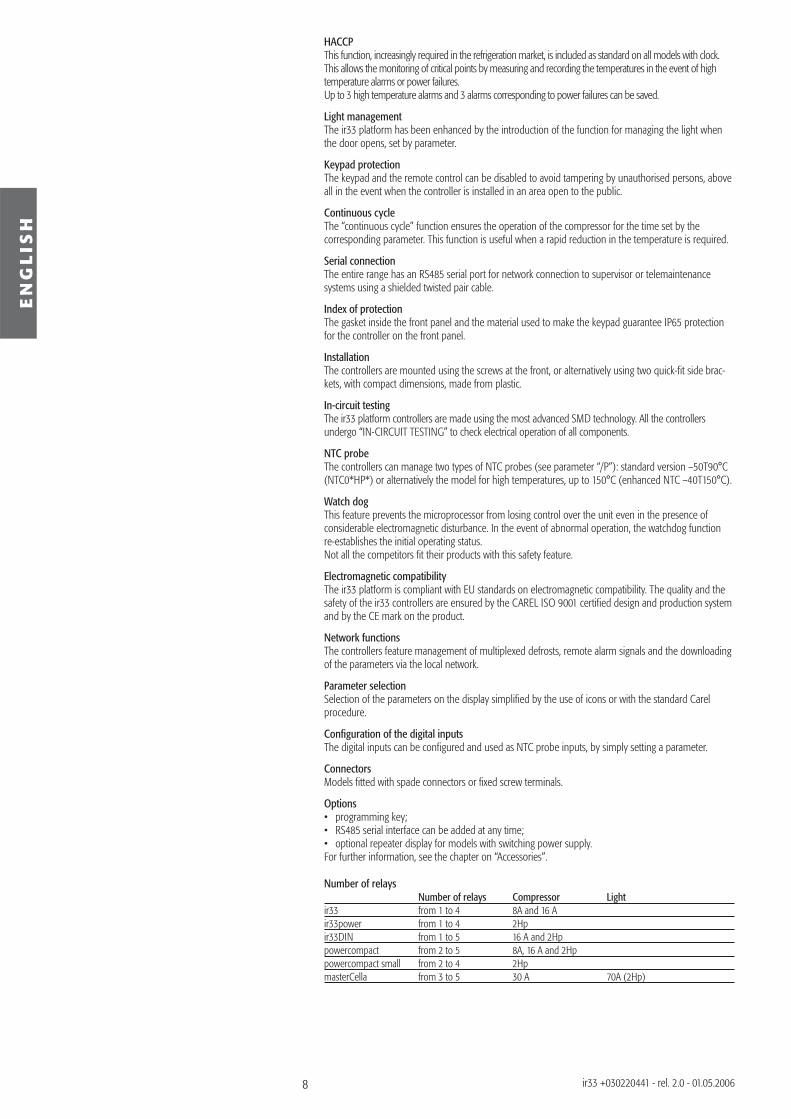
Number of relays Number of relays Compressor Lightir33 from 1 to 4 8A and 16 A ir33power from 1 to 4 2Hp ir33DIN from 1 to 5 16 A and 2Hp powercompact from 2 to 5 8A, 16 A and 2Hp powercompact small from 2 to 4 2Hp masterCella from 3 to 5 30 A 70A (2Hp)
9
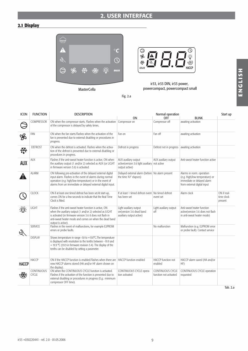
MasterCella ir33, ir33 DIN, ir33 power,
powercompact, powercompact small
Fig. 2.a EN
GL
ISH
ir33 +030220441 - rel. 2.0 - 01.05.2006
2.1 Display
ICON FUNCTION DESCRIPTION Normal operation Start upON OFF BLINK
COMPRESSOR ON when the compressor starts. Flashes when the activation of the compressor is delayed by safety times.
Compressor on Compressor off awaiting activation
FAN ON when the fan starts.Flashes when the activation of the fan is prevented due to external disabling or procedures in progress.
Fan on Fan off awaiting activation
DEFROST ON when the defrost is activated. Flashes when the activa-tion of the defrost is prevented due to external disabling or procedures in progress.
Defrost in progress Defrost not in progress awaiting activation
AUX Flashes if the anti-sweat heater function is active, ON when the auxiliary output (1 and/or 2) selected as AUX (or LIGHT in fi rmware version 3.6) is activated.
AUX auxiliary output active(version 3.6 light auxiliary output active)
AUX auxiliary output not active
Anti-sweat heater function active
ALARM ON following pre-activation of the delayed external digital input alarm. Flashes in the event of alarms during normal operation (e.g. high/low temperature) or in the event of alarms from an immediate or delayed external digital input.
Delayed external alarm (before the time ‘A7’ elapses)
No alarm present Alarms in norm. operation (e.g. High/low temperature) or immediate or delayed alarm from external digital input
CLOCK ON if at least one timed defrost has been set.At start-up, comes ON for a few seconds to indicate that the Real Time Clock is fi tted.
If at least 1 timed defrost event has been set
No timed defrost event set
Alarm clock ON if real-time clock present
LIGHT Flashes if the anti-sweat heater function is active, ON when the auxiliary output (1 and/or 2) selected as LIGHT is activated (in fi rmware version 3.6 it does not fl ash in anti-sweat heater mode and comes on when the dead band output is active).
Light auxiliary output on(version 3.6 dead band auxiliary output active)
Light auxiliary output off
Anti-sweat heater function active(version 3.6 does not fl ash in anti-sweat heater mode)
SERVICE Flashes in the event of malfunctions, for example E2PROM
errors or probe faults.No malfunction Malfunction (e.g. E2PROM error
or probe fault). Contact service
DISPLAY Shows temperature in range -50 to +150°C.The temperature is displayed with resolution to the tenths between –19.9 and + 19.9 °C (59.9 in fi rmware revision 3.4). The display of the tenths can be disabled by setting a parameter.
HACCP ON if the HACCP function is enabled.Flashes when there are
new HACCP alarms stored (HA and/or HF alarm shown on the display).
HACCP function enabled HACCP function not enabled
HACCP alarm saved (HA and/or HF)
CONTINUOUS CYCLE
ON when the CONTINUOUS CYCLE function is activated. Flashes if the activation of the function is prevented due to external disabling or procedures in progress (E.g.: minimum compressor OFF time).
CONTINUOUS CYCLE opera-tion activated
CONTINUOUS CYCLE function not activated
CONTINUOUS CYCLE operation requested
Tab. 2.a
2. USER INTERFACE
10
7
4
8
66 4
78
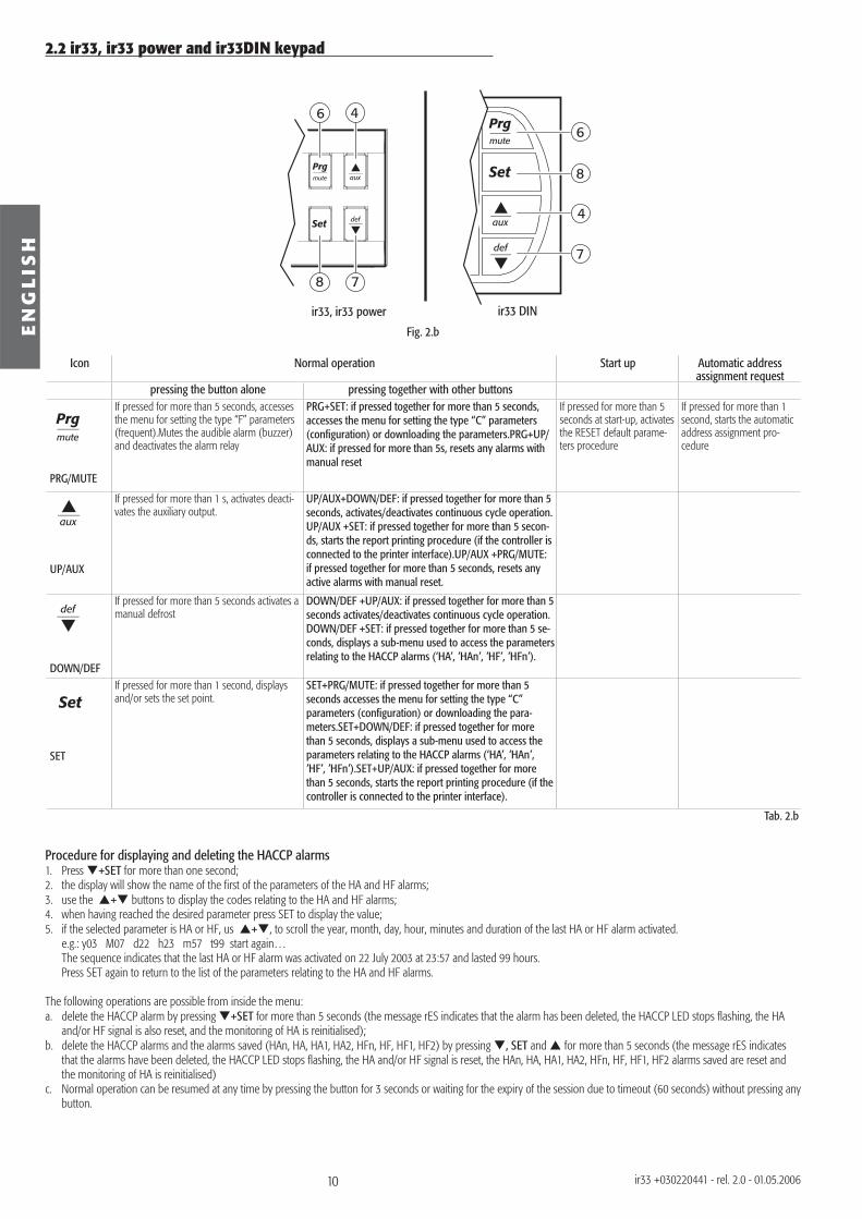
ir33, ir33 power ir33 DIN
Fig. 2.bEN
GL
ISH
ir33 +030220441 - rel. 2.0 - 01.05.2006
Icon Normal operation Start up Automatic address assignment request
pressing the button alone pressing together with other buttons
PRG/MUTE
If pressed for more than 5 seconds, accesses the menu for setting the type “F” parameters (frequent).Mutes the audible alarm (buzzer) and deactivates the alarm relay
PRG+SET: if pressed together for more than 5 seconds, accesses the menu for setting the type “C” parameters (confi guration) or downloading the parameters.PRG+UP/AUX: if pressed for more than 5s, resets any alarms with manual reset
If pressed for more than 5 seconds at start-up, activates the RESET default parame-ters procedure
If pressed for more than 1 second, starts the automatic address assignment pro-cedure
aux
UP/AUX
If pressed for more than 1 s, activates deacti-vates the auxiliary output.
UP/AUX+DOWN/DEF: if pressed together for more than 5 seconds, activates/deactivates continuous cycle operation.UP/AUX +SET: if pressed together for more than 5 secon-ds, starts the report printing procedure (if the controller is connected to the printer interface).UP/AUX +PRG/MUTE: if pressed together for more than 5 seconds, resets any active alarms with manual reset.
def
DOWN/DEF
If pressed for more than 5 seconds activates a manual defrost
DOWN/DEF +UP/AUX: if pressed together for more than 5 seconds activates/deactivates continuous cycle operation.DOWN/DEF +SET: if pressed together for more than 5 se-conds, displays a sub-menu used to access the parameters relating to the HACCP alarms (‘HA’, ’HAn’, ’HF’, ’HFn’).
Set
SET
If pressed for more than 1 second, displays and/or sets the set point.
SET+PRG/MUTE: if pressed together for more than 5 seconds accesses the menu for setting the type “C” parameters (confi guration) or downloading the para-meters.SET+DOWN/DEF: if pressed together for more than 5 seconds, displays a sub-menu used to access the parameters relating to the HACCP alarms (‘HA’, ’HAn’, ’HF’, ’HFn’).SET+UP/AUX: if pressed together for more than 5 seconds, starts the report printing procedure (if the controller is connected to the printer interface).
Tab. 2.b
Procedure for displaying and deleting the HACCP alarms 1. Press +SET for more than one second;2. the display will show the name of the fi rst of the parameters of the HA and HF alarms;3. use the + buttons to display the codes relating to the HA and HF alarms;4. when having reached the desired parameter press SET to display the value;5. if the selected parameter is HA or HF, us + , to scroll the year, month, day, hour, minutes and duration of the last HA or HF alarm activated. e.g.: y03 M07 d22 h23 m57 t99 start again… The sequence indicates that the last HA or HF alarm was activated on 22 July 2003 at 23:57 and lasted 99 hours. Press SET again to return to the list of the parameters relating to the HA and HF alarms.
The following operations are possible from inside the menu: a. delete the HACCP alarm by pressing +SET for more than 5 seconds (the message rES indicates that the alarm has been deleted, the HACCP LED stops fl ashing, the HA
and/or HF signal is also reset, and the monitoring of HA is reinitialised);b. delete the HACCP alarms and the alarms saved (HAn, HA, HA1, HA2, HFn, HF, HF1, HF2) by pressing , SET and for more than 5 seconds (the message rES indicates
that the alarms have been deleted, the HACCP LED stops fl ashing, the HA and/or HF signal is reset, the HAn, HA, HA1, HA2, HFn, HF, HF1, HF2 alarms saved are reset and the monitoring of HA is reinitialised)
c. Normal operation can be resumed at any time by pressing the button for 3 seconds or waiting for the expiry of the session due to timeout (60 seconds) without pressing any button.
2.2 ir33, ir33 power and ir33DIN keypad
11
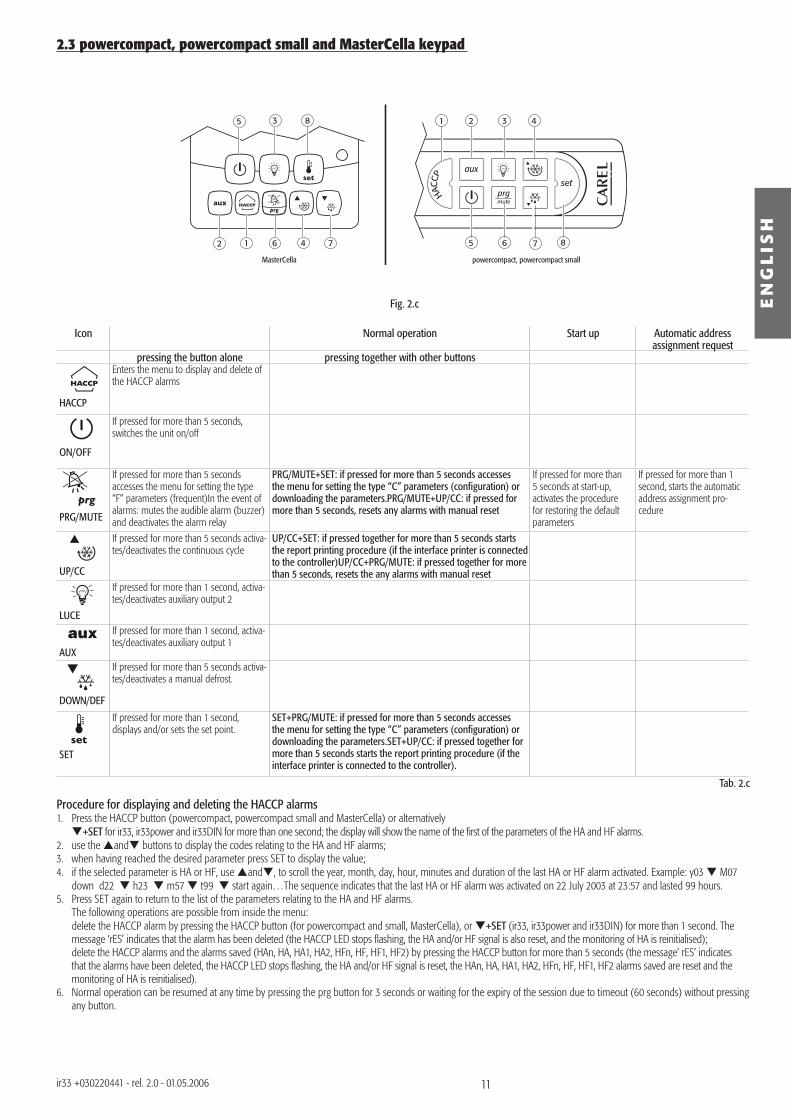
65 7 8
2 3 41
12 6 4 7
5 3 8
MasterCella powercompact, powercompact small
Fig. 2.c EN
GL
ISH
ir33 +030220441 - rel. 2.0 - 01.05.2006
Icon Normal operation Start up Automatic address assignment request
pressing the button alone pressing together with other buttons
HACCP
Enters the menu to display and delete of the HACCP alarms
ON/OFF
If pressed for more than 5 seconds, switches the unit on/off
PRG/MUTE
If pressed for more than 5 seconds accesses the menu for setting the type “F” parameters (frequent)In the event of alarms: mutes the audible alarm (buzzer) and deactivates the alarm relay
PRG/MUTE+SET: if pressed for more than 5 seconds accesses the menu for setting the type “C” parameters (confi guration) or downloading the parameters.PRG/MUTE+UP/CC: if pressed for more than 5 seconds, resets any alarms with manual reset
If pressed for more than 5 seconds at start-up, activates the procedure for restoring the default parameters
If pressed for more than 1 second, starts the automatic address assignment pro-cedure
UP/CC
If pressed for more than 5 seconds activa-tes/deactivates the continuous cycle
UP/CC+SET: if pressed together for more than 5 seconds starts the report printing procedure (if the interface printer is connected to the controller)UP/CC+PRG/MUTE: if pressed together for more than 5 seconds, resets the any alarms with manual reset
LUCE
If pressed for more than 1 second, activa-tes/deactivates auxiliary output 2
AUX
If pressed for more than 1 second, activa-tes/deactivates auxiliary output 1
DOWN/DEF
If pressed for more than 5 seconds activa-tes/deactivates a manual defrost.
SET
If pressed for more than 1 second, displays and/or sets the set point.
SET+PRG/MUTE: if pressed for more than 5 seconds accesses the menu for setting the type “C” parameters (confi guration) or downloading the parameters.SET+UP/CC: if pressed together for more than 5 seconds starts the report printing procedure (if the interface printer is connected to the controller).
2.3 powercompact, powercompact small and MasterCella keypad
Procedure for displaying and deleting the HACCP alarms1. Press the HACCP button (powercompact, powercompact small and MasterCella) or alternatively +SET for ir33, ir33power and ir33DIN for more than one second; the display will show the name of the first of the parameters of the HA and HF alarms.2. use the and buttons to display the codes relating to the HA and HF alarms;3. when having reached the desired parameter press SET to display the value;4. if the selected parameter is HA or HF, use and , to scroll the year, month, day, hour, minutes and duration of the last HA or HF alarm activated. Example: y03 M07
down d22 h23 m57 t99 start again…The sequence indicates that the last HA or HF alarm was activated on 22 July 2003 at 23:57 and lasted 99 hours.5. Press SET again to return to the list of the parameters relating to the HA and HF alarms. The following operations are possible from inside the menu: delete the HACCP alarm by pressing the HACCP button (for powercompact and small, MasterCella), or +SET (ir33, ir33power and ir33DIN) for more than 1 second. The
message ‘rES’ indicates that the alarm has been deleted (the HACCP LED stops fl ashing, the HA and/or HF signal is also reset, and the monitoring of HA is reinitialised); delete the HACCP alarms and the alarms saved (HAn, HA, HA1, HA2, HFn, HF, HF1, HF2) by pressing the HACCP button for more than 5 seconds (the message’ rES’ indicates
that the alarms have been deleted, the HACCP LED stops fl ashing, the HA and/or HF signal is reset, the HAn, HA, HA1, HA2, HFn, HF, HF1, HF2 alarms saved are reset and the monitoring of HA is reinitialised).
6. Normal operation can be resumed at any time by pressing the prg button for 3 seconds or waiting for the expiry of the session due to timeout (60 seconds) without pressing any button.
Tab. 2.c
12
EN
GL
ISH
ir33 +030220441 - rel. 2.0 - 01.05.2006
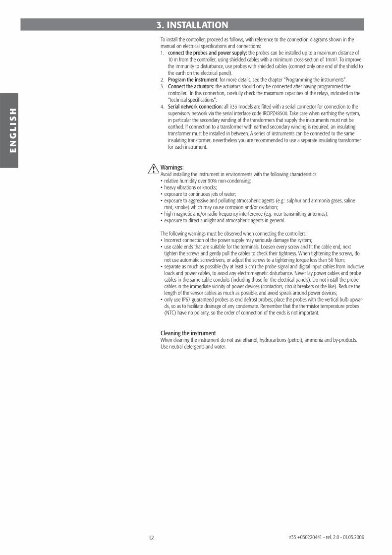
3. INSTALLATIONTo install the controller, proceed as follows, with reference to the connection diagrams shown in the manual on electrical specifi cations and connections:1. connect the probes and power supply: the probes can be installed up to a maximum distance of
10 m from the controller, using shielded cables with a minimum cross-section of 1mm². To improve the immunity to disturbance, use probes with shielded cables (connect only one end of the shield to the earth on the electrical panel).
2. Program the instrument: for more details, see the chapter “Programming the instruments”.3. Connect the actuators: the actuators should only be connected after having programmed the
controller. In this connection, carefully check the maximum capacities of the relays, indicated in the “technical specifi cations”.
4. Serial network connection: all ir33 models are fi tted with a serial connector for connection to the supervisory network via the serial interface code IROPZ48500. Take care when earthing the system, in particular the secondary winding of the transformers that supply the instruments must not be earthed. If connection to a transformer with earthed secondary winding is required, an insulating transformer must be installed in between. A series of instruments can be connected to the same insulating transformer, nevertheless you are recommended to use a separate insulating transformer for each instrument.
Warnings:Avoid installing the instrument in environments with the following characteristics:• relative humidity over 90% non-condensing;• heavy vibrations or knocks;• exposure to continuous jets of water;• exposure to aggressive and polluting atmospheric agents (e.g.: sulphur and ammonia gases, saline
mist, smoke) which may cause corrosion and/or oxidation;• high magnetic and/or radio frequency interference (e.g. near transmitting antennas);• exposure to direct sunlight and atmospheric agents in general.
The following warnings must be observed when connecting the controllers:• Incorrect connection of the power supply may seriously damage the system;• use cable ends that are suitable for the terminals. Loosen every screw and fi t the cable end, next
tighten the screws and gently pull the cables to check their tightness. When tightening the screws, do not use automatic screwdrivers, or adjust the screws to a tightening torque less than 50 Ncm;
• separate as much as possible (by at least 3 cm) the probe signal and digital input cables from inductive loads and power cables, to avoid any electromagnetic disturbance. Never lay power cables and probe cables in the same cable conduits (including those for the electrical panels). Do not install the probe cables in the immediate vicinity of power devices (contactors, circuit breakers or the like). Reduce the length of the sensor cables as much as possible, and avoid spirals around power devices;
• only use IP67 guaranteed probes as end defrost probes; place the probes with the vertical bulb upwar-ds, so as to facilitate drainage of any condensate. Remember that the thermistor temperature probes (NTC) have no polarity, so the order of connection of the ends is not important.
Cleaning the instrumentWhen cleaning the instrument do not use ethanol, hydrocarbons (petrol), ammonia and by-products.Use neutral detergents and water.
13
EN
GL
ISH
ir33 +030220441 - rel. 2.0 - 01.05.2006
The operating parameters can be modifi ed using the front keypad, and are divided into two families: frequent use parameters (type “F”) and confi guration parameters (type “C”). Access to the confi guration parameters is protected by a password that prevents unwanted modifi cations or access by unauthorised persons.How to access type “F” parameters (frequent use):press PRG for more than 5 seconds (if an alarm is active, the buzzer is muted fi rst of all), the display shows the code of the fi rst modifi able type “F” parameter.How to access type “C” parameters (confi guration):1. Press prg and SET together for more than 5 seconds; the display will show the number “00”, representing the password prompt;2. press or until displaying the number “22” (the code of the password allows access to the
parameters);3. confi rm by pressing SET; the display will show the code of the fi rst modifi able type “C” parameter.
4.1 Modifying the parametersAfter having displayed the parameter, either type “C” or type “F”, proceed as follows:1. press or suntil reaching the parameter to be modifi ed. When scrolling, an icon appears on
the display representing the category the parameter belongs to. Alternatively, press prg to display a menu that is used to quickly access the family of parameters to be modifi ed;
2. scroll the menu with the and buttons; the display shows the codes of the various categories of parameters (see the “Summary of operating parameters”), accompanied by the display of the corresponding icon (if present);
3. when having reached the desired category, press SET to move directly to the fi rst parameter in the category (if there are no visible parameters in the selected category, pressing SET will have no effect);
4. at this stage, continue to scroll the parameters, or return to the categories menu by pressing prg; 5. press SET to display the value associated with the parameter;6. increase or decrease the value using the or button respectively;7. press SET to temporarily save the new value and return to the display of the parameter code. Repeat
the operations from point 1 or point 2;8. if the parameter has sub-parameters, press SET to display the fi rst sub-parameter;9. press or to display all the sub-parameters;10. press SET to display the associated value;11. increase or decrease the value using the or button respectively;12. press SET to temporarily save the new value and return to the display of the sub-parameter code;13. press prg to return to the display of the parent parameter.
4.2 Storing the new values assigned to the parametersTo defi nitively store the new values of the modifi ed parameters, press prg for more than 5 seconds, thus exiting the parameter setting procedure. All the modifi cations made to the parameters, temporarily stored in the RAM, can be cancelled and “normal operation” resumed by not pressing any button for 60 seconds, thus allowing the parameter setting session to expire due to timeout. Important: if the programming session ends by timeout, the clock parameters will not be reset, as these parameters are saved immediately when entered.If the instrument is switched off before pressing prg, all the modifi cations made to the parameters and temporarily saved will be lost.
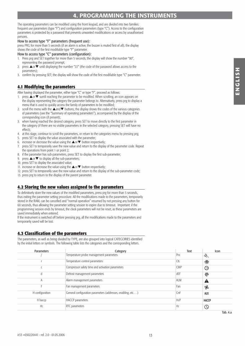
4.3 Classifi cation of the parametersThe parameters, as well as being divided by TYPE, are also grouped into logical CATEGORIES identifi ed by the initial letters or symbols. The following table lists the categories and the corresponding letters.
Parameters Category Text Icon/ Temperature probe management parameters Pro
r Temperature control parameters CtL
c Compressor safety time and activation parameters CMP
d Defrost management parameters dEF
A Alarm management parameters ALM
F Fan management parameters Fan
H confi guration General confi guration parameters (addresses, enabling, etc.…) CnF
H haccp HACCP parameters HcP
rtc RTC parameters rtc
Tab. 4.a
4. PROGRAMMING THE INSTRUMENTS
14
EN
GL
ISH
ir33 +030220441 - rel. 2.0 - 01.05.2006
4.4 Downloading the parameters via the network1. Press the prg and SET buttons together for more than 5 seconds; the display will show the number “00”;2. press the or button to scroll the numbers until displaying “66” (download activation password),
then confi rm by pressing SET;3. the display will show the message “dnL”, indicating that the download is in progress;4. at the end of the procedure, the message “dnL” is cancelled and, in the event of errors, one of the
messages d1 to d6 is displayed to indicate which unit the error occurred on.
4.5 Setting the set point1. Press SET for more than 1 second to display the set point;2. increase or decrease the set point using the or buttons respectively, until reaching the desired
value;3. press SET again to confi rm the new value.
4.6 Alarms with manual resetThe alarms with manual reset can be reset by pressing prg and ptogether for more than 5 seconds, if the causes are no longer present.
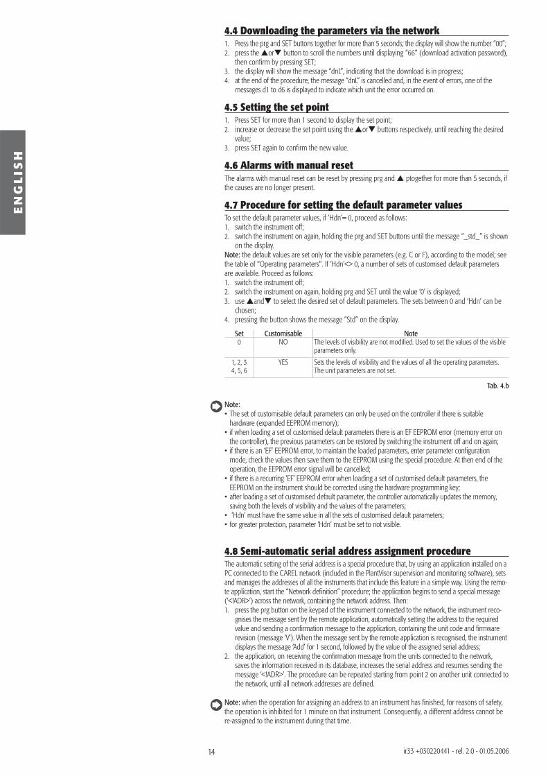
4.7 Procedure for setting the default parameter valuesTo set the default parameter values, if ‘Hdn’= 0, proceed as follows:1. switch the instrument off;2. switch the instrument on again, holding the prg and SET buttons until the message “_std_” is shown
on the display.Note: the default values are set only for the visible parameters (e.g. C or F), according to the model; see the table of “Operating parameters”. If ‘Hdn’<> 0, a number of sets of customised default parameters are available. Proceed as follows:1. switch the instrument off;2. switch the instrument on again, holding prg and SET until the value ‘0’ is displayed;3. use and to select the desired set of default parameters. The sets between 0 and ‘Hdn’ can be
chosen;4. pressing the button shows the message “Std” on the display.
Set Customisable Note0 NO The levels of visibility are not modifi ed. Used to set the values of the visible
parameters only.
1, 2, 34, 5, 6
YES Sets the levels of visibility and the values of all the operating parameters. The unit parameters are not set.
Tab. 4.b
Note:• The set of customisable default parameters can only be used on the controller if there is suitable hardware (expanded EEPROM memory);• if when loading a set of customised default parameters there is an EF EEPROM error (memory error on
the controller), the previous parameters can be restored by switching the instrument off and on again;• if there is an ‘EF’ EEPROM error, to maintain the loaded parameters, enter parameter confi guration
mode, check the values then save them to the EEPROM using the special procedure. At then end of the operation, the EEPROM error signal will be cancelled;
• if there is a recurring ‘EF’ EEPROM error when loading a set of customised default parameters, the EEPROM on the instrument should be corrected using the hardware programming key;
• after loading a set of customised default parameter, the controller automatically updates the memory, saving both the levels of visibility and the values of the parameters;
• ‘Hdn’ must have the same value in all the sets of customised default parameters;• for greater protection, parameter ‘Hdn’ must be set to not visible.
4.8 Semi-automatic serial address assignment procedureThe automatic setting of the serial address is a special procedure that, by using an application installed on a PC connected to the CAREL network (included in the PlantVisor supervision and monitoring software), sets and manages the addresses of all the instruments that include this feature in a simple way. Using the remo-te application, start the “Network defi nition” procedure; the application begins to send a special message (‘<!ADR>’) across the network, containing the network address. Then:1. press the prg button on the keypad of the instrument connected to the network, the instrument reco-
gnises the message sent by the remote application, automatically setting the address to the required value and sending a confi rmation message to the application, containing the unit code and fi rmware revision (message ‘V’). When the message sent by the remote application is recognised, the instrument displays the message ‘Add’ for 1 second, followed by the value of the assigned serial address;
2. the application, on receiving the confi rmation message from the units connected to the network, saves the information received in its database, increases the serial address and resumes sending the message ‘<!ADR>‘. The procedure can be repeated starting from point 2 on another unit connected to the network, until all network addresses are defi ned.
Note: when the operation for assigning an address to an instrument has fi nished, for reasons of safety, the operation is inhibited for 1 minute on that instrument. Consequently, a different address cannot be re-assigned to the instrument during that time.
15
EN
GL
ISH
ir33 +030220441 - rel. 2.0 - 01.05.2006
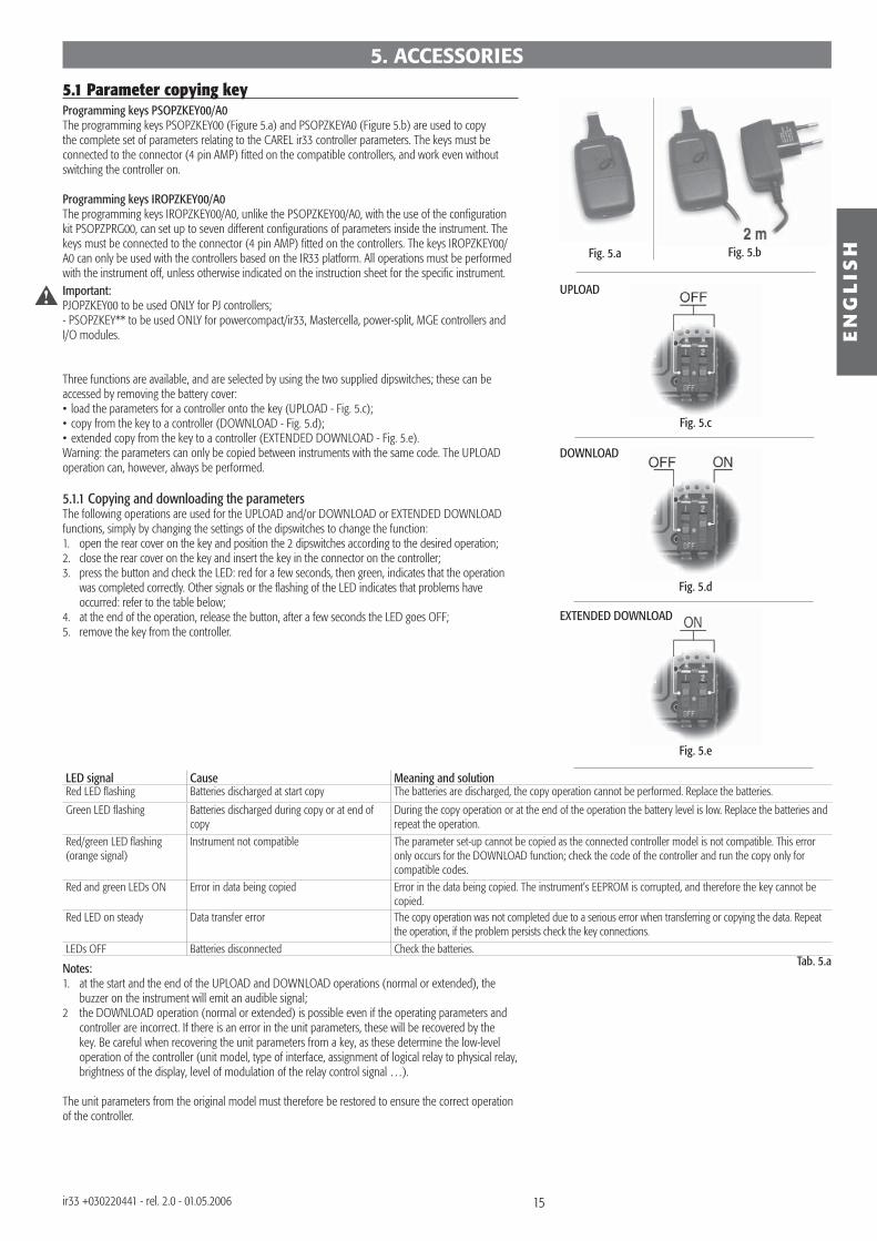
5.1 Parameter copying keyProgramming keys PSOPZKEY00/A0The programming keys PSOPZKEY00 (Figure 5.a) and PSOPZKEYA0 (Figure 5.b) are used to copy the complete set of parameters relating to the CAREL ir33 controller parameters. The keys must be connected to the connector (4 pin AMP) fi tted on the compatible controllers, and work even without switching the controller on. Programming keys IROPZKEY00/A0The programming keys IROPZKEY00/A0, unlike the PSOPZKEY00/A0, with the use of the confi guration kit PSOPZPRG00, can set up to seven different confi gurations of parameters inside the instrument. The keys must be connected to the connector (4 pin AMP) fi tted on the controllers. The keys IROPZKEY00/A0 can only be used with the controllers based on the IR33 platform. All operations must be performed with the instrument off, unless otherwise indicated on the instruction sheet for the specifi c instrument.Important: PJOPZKEY00 to be used ONLY for PJ controllers; - PSOPZKEY** to be used ONLY for powercompact/ir33, Mastercella, power-split, MGE controllers and I/O modules.
Three functions are available, and are selected by using the two supplied dipswitches; these can be accessed by removing the battery cover:• load the parameters for a controller onto the key (UPLOAD - Fig. 5.c);• copy from the key to a controller (DOWNLOAD - Fig. 5.d);• extended copy from the key to a controller (EXTENDED DOWNLOAD - Fig. 5.e).Warning: the parameters can only be copied between instruments with the same code. The UPLOAD operation can, however, always be performed.
5.1.1 Copying and downloading the parametersThe following operations are used for the UPLOAD and/or DOWNLOAD or EXTENDED DOWNLOAD functions, simply by changing the settings of the dipswitches to change the function:1. open the rear cover on the key and position the 2 dipswitches according to the desired operation;2. close the rear cover on the key and insert the key in the connector on the controller;3. press the button and check the LED: red for a few seconds, then green, indicates that the operation
was completed correctly. Other signals or the fl ashing of the LED indicates that problems have occurred: refer to the table below;4. at the end of the operation, release the button, after a few seconds the LED goes OFF;5. remove the key from the controller.
LED signal Cause Meaning and solutionRed LED fl ashing Batteries discharged at start copy The batteries are discharged, the copy operation cannot be performed. Replace the batteries.
Green LED fl ashing Batteries discharged during copy or at end of copy
During the copy operation or at the end of the operation the battery level is low. Replace the batteries and repeat the operation.
Red/green LED fl ashing (orange signal)
Instrument not compatible The parameter set-up cannot be copied as the connected controller model is not compatible. This error only occurs for the DOWNLOAD function; check the code of the controller and run the copy only for compatible codes.
Red and green LEDs ON Error in data being copied Error in the data being copied. The instrument’s EEPROM is corrupted, and therefore the key cannot be copied.
Red LED on steady Data transfer error The copy operation was not completed due to a serious error when transferring or copying the data. Repeat the operation, if the problem persists check the key connections.
LEDs OFF Batteries disconnected Check the batteries.
Notes:1. at the start and the end of the UPLOAD and DOWNLOAD operations (normal or extended), the
buzzer on the instrument will emit an audible signal;2 the DOWNLOAD operation (normal or extended) is possible even if the operating parameters and
controller are incorrect. If there is an error in the unit parameters, these will be recovered by the key. Be careful when recovering the unit parameters from a key, as these determine the low-level operation of the controller (unit model, type of interface, assignment of logical relay to physical relay, brightness of the display, level of modulation of the relay control signal …).
The unit parameters from the original model must therefore be restored to ensure the correct operation of the controller.
5. ACCESSORIES
Fig. 5.a Fig. 5.b
Fig. 5.c
Fig. 5.d
Fig. 5.e
UPLOAD
DOWNLOAD
EXTENDED DOWNLOAD
Tab. 5.a

16
Fig. 5.f
Fig. 5.h
Fig. 5.g
Fig. 5.i
EN
GL
ISH
ir33 +030220441 - rel. 2.0 - 01.05.2006
5.2 Remote controlThe compact remote control with 22 buttons, allows direct access to the following parameters (Fig. 5.f):• temperature;• defrost;• fans;• alarms;• HACCP.The following functions can also be controlled:• start defrost;• AUX;• light;• ON/OFF;• mute.The standard remote control features the four buttons, PRG/mute, SET, UP and DOWN, which access almost all the functions provided by the instrument keypad. The buttons can be divided into three groups, based on their functions:• Buttons for enabling and disabling the use of the remote control (Figure 5.g);• Buttons for remote simulation of the instrument keypad (Figure 5.h);• Buttons for direct display/modifi cation of the most commonly used parameters (Figure 5.i).
Activating and deactivating the use of the remote control
Button Immediate function Delayed functionSTART used to enable the remote control; each instrument
displays its own enabling code
EXIT ends operation using the remote control, cancelling all changes made to the parameters
PRG used to display the confi guration parameters pressing and holding for 5s ends use of the remote control, saving the modifi ed parameters.
NUMBERS used to select the instrument, by entering the enabling code displayed.
Tab. 5.b
By pressing the START button, each instrument displays its own remote control enabling code (H3). The numeric keypad is used to enter the enabling code of the instrument in question. At the end of this operation, only the instrument with the selected enabling code will be programmed from the remote control, all the others will resume normal operation. Assigning different enabling codes to the instruments, allows, in this phase, only the desired instrument to be programmed using the remote control, without the risk of interference. The instrument enabled for programming from the remote control will display the reading and the message rCt. This status is called Level 0.When having entered programming mode, pressing prg for 5 seconds exits the programming of the remote control, saving the modifi cations; vice-versa, press EXIT to exit the programming of the remote control, without saving the modifi cations
Remote simulation of the instrument keypadThe highlighted part is used to simulate the instrument keypad from the remote control.In Level 0 (display the reading and message rCt), the following functions are active:
Button Immediate functiondef start and stop defrostingaux activation and deactivation of auxiliary relay 1light activation and deactivation of auxiliary relay 2ON/OFF instrument ON/OFFPRG/mute mute the buzzer, if ON, and deactivate the alarm relay
Tab. 5.c
In this level, the set and PRG/mute buttons are also active, used to activate the set point (Level 1) and the confi guration parameters (Level 2).
Button Immediate function Delayed functionPRG/mute modify the confi guration parameters pressing and holding for 5s saves the
modifi ed parametersset modify the set point
Tab. 5.dIn Levels 1 and Level 2, the PRG/mute, SET, UP and DOWN buttons repeat the corresponding functions on the instrument keypad. In this way, all the instrument parameters can be displayed and modifi ed, even those without shortcut buttons.
Directly display/modify the most commonly used parameters: Some parameters, relating to: Temperature, Defrost, Alarms, Fans, HACCPare directly accessible using specifi c buttons.
17
Fig. 5.l
Fig. 5.m
Fig. 5.n
Fig. 5.o
Fig. 5.p
Fig. 5.q
EN
GL
ISH
ir33 +030220441 - rel. 2.0 - 01.05.2006
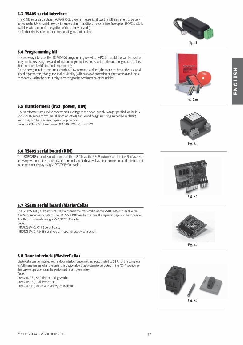
5.3 RS485 serial interfaceThe RS485 serial card option (IROPZ48500), shown in Figure 5.l, allows the ir33 instrument to be con-nected to the RS485 serial network for supervision. In addition, the serial interface option IROPZ485S0 is available, with automatic recognition of the polarity (+ and -).For further details, refer to the corresponding instruction sheet.
5.4 Programming kit This accessory interfaces the IROPZKEY00 programming key with any PC; this useful tool can be used to program the key using the standard instrument parameters, and save the different confi gurations to fi les that can be recalled during fi nal programming. For the new generation instruments, such as powercompact and ir33, the user can change the password, hide the parameters, change the level of visibility (with password protection or direct access) and, most importantly, assign the output relays according to the confi guration of the utilities.
5.5 Transformers (ir33, power, DIN) The transformers are used to convert mains voltage to the power supply voltage specifi ed for the ir33 and ir33DIN series controllers. Their compactness and sound design (winding immersed in plastic) mean they can be used in all types of applications.Code: TRA12VDE00: Transformer, 3VA 240/12VAC VDE - 153/M
5.6 RS485 serial board (DIN)The IROPZSER30 board is used to connect the ir33DIN via the RS485 network serial to the PlantVisor su-pervisory system (using the removable terminal supplied), as well as direct connection of the instrument to the repeater display using a PSTCON**B00 cable.
5.7 RS485 serial board (MasterCella)The IROPZSEM10/30 boards are used to connect the mastercella via the RS485 network serial to the PlantVisor supervisory system. The IROPZSEM30 board also allows the repeater display to be connected directly to mastercella using a PSTCON**B00 cable.Codes:• IROPZSEM10: RS485 serial board;• IROPZSEM30: RS485 serial board + repeater display connection.
5.8 Door interlock (MasterCella)Mastercella can be installed with a door interlock disconnecting switch, rated to 32 A, for the complete on/off management of all the units; this device allows the system to be locked in the “Off” position so that service operations can be performed in complete safety. Codes:• 0402512CEL, 32 A disconnecting switch;• 0402515CEL, shaft H=85mm;• 0402517CEL, switch with yellow/red indicator.
18
ir33powercompactpowercompact small
IROPZDSP00 PSTCON0**B0
IR00R*0000
PSTCON0**00
IR00R*0000
IROPZSEM30
MasterCella
ir33 DIN
PSTCON0**B0
IR00R*0000
IROPZSER30
Fig. 5.r
Fig. 5.s
Fig. 5.t
Fig. 5.u
Fig. 5.v
EN
GL
ISH
ir33 +030220441 - rel. 2.0 - 01.05.2006
Fig. 5.s
Fig. 5.t
Fig. 5.u
Fig. 5.v
Fig. 5.r
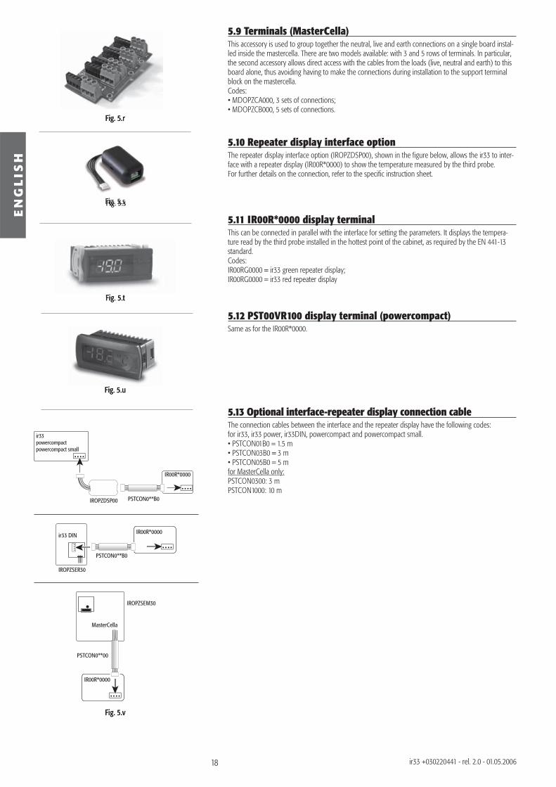
5.9 Terminals (MasterCella)This accessory is used to group together the neutral, live and earth connections on a single board instal-led inside the mastercella. There are two models available: with 3 and 5 rows of terminals. In particular, the second accessory allows direct access with the cables from the loads (live, neutral and earth) to this board alone, thus avoiding having to make the connections during installation to the support terminal block on the mastercella.Codes:• MDOPZCA000, 3 sets of connections;• MDOPZCB000, 5 sets of connections.
5.10 Repeater display interface optionThe repeater display interface option (IROPZDSP00), shown in the fi gure below, allows the ir33 to inter-face with a repeater display (IR00R*0000) to show the temperature measured by the third probe.For further details on the connection, refer to the specifi c instruction sheet.
5.11 IR00R*0000 display terminalThis can be connected in parallel with the interface for setting the parameters. It displays the tempera-ture read by the third probe installed in the hottest point of the cabinet, as required by the EN 441-13 standard.Codes:IR00RG0000 = ir33 green repeater display;IR00RG0000 = ir33 red repeater display
5.12 PST00VR100 display terminal (powercompact)Same as for the IR00R*0000.
5.13 Optional interface-repeater display connection cableThe connection cables between the interface and the repeater display have the following codes:for ir33, ir33 power, ir33DIN, powercompact and powercompact small.• PSTCON01B0 = 1.5 m• PSTCON03B0 = 3 m• PSTCON05B0 = 5 mfor MasterCella only:PSTCON0300: 3 mPSTCON1000: 10 m
19
EN
GL
ISH
ir33 +030220441 - rel. 2.0 - 01.05.2006
6. DESCRIPTION OF THE FUNCTIONS
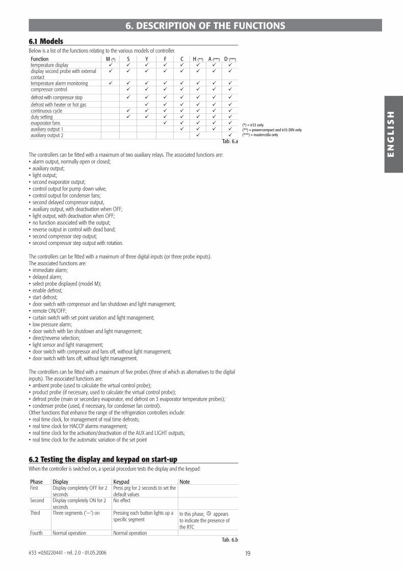
6.1 ModelsBelow is a list of the functions relating to the various models of controller.Function M (*) S Y F C H (**) A (***) D (***)temperature displaydisplay second probe with external contacttemperature alarm monitoringcompressor control
defrost with compressor stop defrost with heater or hot gascontinuous cycleduty settingevaporator fans auxiliary output 1auxiliary output 2
Tab. 6.a
The controllers can be fi tted with a maximum of two auxiliary relays. The associated functions are:• alarm output, normally open or closed;• auxiliary output;• light output;• second evaporator output;• control output for pump down valve;• control output for condenser fans;• second delayed compressor output,• auxiliary output, with deactivation when OFF;• light output, with deactivation when OFF;• no function associated with the output;• reverse output in control with dead band;• second compressor step output;• second compressor step output with rotation.
The controllers can be fi tted with a maximum of three digital inputs (or three probe inputs). The associated functions are:• immediate alarm;• delayed alarm;• select probe displayed (model M);• enable defrost;• start defrost;• door switch with compressor and fan shutdown and light management;• remote ON/OFF;• curtain switch with set point variation and light management;• low pressure alarm;• door switch with fan shutdown and light management;• direct/reverse selection;• light sensor and light management;• door switch with compressor and fans off, without light management;• door switch with fans off, without light management.
The controllers can be fi tted with a maximum of fi ve probes (three of which as alternatives to the digital inputs). The associated functions are:• ambient probe (used to calculate the virtual control probe);• product probe (if necessary, used to calculate the virtual control probe);• defrost probe (main or secondary evaporator, end defrost on 3 evaporator temperature probes);• condenser probe (used, if necessary, for condenser fan control).Other functions that enhance the range of the refrigeration controllers include:• real time clock, for management of real time defrosts;• real time clock for HACCP alarms management;• real time clock for the activation/deactivation of the AUX and LIGHT outputs;• real time clock for the automatic variation of the set point
6.2 Testing the display and keypad on start-upWhen the controller is switched on, a special procedure tests the display and the keypad:
Phase Display Keypad NoteFirst Display completely OFF for 2
secondsPress prg for 2 seconds to set the default values
Second Display completely ON for 2 seconds
No effect
Third Three segments (‘---’) on Pressing each button lights up a specifi c segment
In this phase, appears to indicate the presence of the RTC
Fourth Normal operation Normal operationTab. 6.b
(*) = ir33 only(**) = powercompact and ir33 DIN only(***) = mastercella only
20
EN
GL
ISH
ir33 +030220441 - rel. 2.0 - 01.05.2006
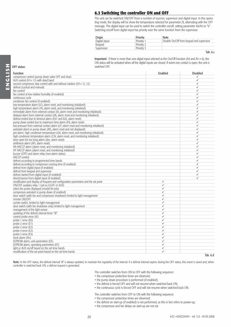
6.3 Switching the controller ON and OFFThe unit can be switched ON/OFF from a number of sources; supervisor and digital input. In this opera-ting mode, the display will be show the temperature selected for parameter /tI, alternating with the OFF message. The digital input can be used to switch the controller on/off, setting parameter A4/A5 to “6”. Switching on/off from digital input has priority over the same function from the supervisor.
Origin Priority NoteDigital input Priority 1 Disable On/Off from keypad and supervisorKeypad Priority 2Supervisor Priority 3
Tab. 6.c
Important: if there is more than one digital input selected as the On/Off function (A4 and A5 = 6), the ON status will be activated when all the digital inputs are closed. If event one contact is open, the unit is switched OFF.
Function Enabled Disabledcompressor control (pump down valve OFF and shut)AUX control (H1= 11) with dead bandsecond compressor step control with and without rotation (H1= 12, 13)defrost (cyclical and manual)fan controlfan control at low relative humidity (if enabled)continuous cyclecondenser fan control (if enabled)low temperature alarm (LO, alarm reset, and monitoring initialised)high temperature alarm (HI, alarm reset, and monitoring initialised)immediate alarm from external contact (IA, alarm reset and monitoring initialised)delayed alarm from external contact (dA, alarm reset and monitoring initialised)defrost ended due to timeout alarm (Ed1 and Ed2, alarm reset)pump down ended due to maximum time alarm (Pd, alarm reset)low pressure from external contact alarm (LP, alarm reset and monitoring initialised)autostart alarm in pump down (AtS, alarm reset and not displayed)pre-alarm: high condenser temperature (cht, alarm reset, and monitoring initialised)high condenser temperature alarm (Cht, alarm reset, and monitoring initialised)door open for too long alarm (dor, alarm reset)antifreeze alarm (AFr, alarm reset)HA HACCP alarm (alarm reset, and monitoring initialised)HF HACCP alarm (alarm reset, and monitoring initialised)buzzer (OFF) and alarm relay (non-alarm status)HACCP controldefrost according to programmed time bandsdefrost according to compressor running time (if enabled)defrost from digital input (if enabled)defrost from keypad and supervisor defrost started from digital input (if enabled)direct/reverse from digital input (if enabled).modifi cation and display of frequent and confi guration parameters and the set pointON/OFF auxiliary relay 1 (set as LIGHT or AUX)select the probe displayed (model M only)compressor autostart in pump down (if enabled)door switch (with fan and compressor shutdown) limited to light managementremote ON/OFFcurtain switch, limited to light managementdoor switch (with fan shutdown only) limited to light managementmanagement of the light sensorupdating of the defrost interval timer “dI”control probe error (rE)probe 1 error (E0)probe 2 error (E1)probe 3 error (E2)probe 4 error (E3)probe 5 error (E4)clock alarm (Etc)EEPROM alarm, unit parameters (EE)EEPROM alarm, operating parameters (EF)light or AUX on/off based on the set time bandsmodifi cation of the set point based on the set time bands
Tab. 6.d
Note: In the OFF status, the defrost interval ‘dI’ is always updated, to maintain the regularity of the interval. If a defrost interval expires during the OFF status, this event is saved and, when controller is switched back ON, a defrost request is generated.
The controller switches from ON to OFF with the following sequence:• the compressor protection times are observed;• the pump down procedure is performed (if enabled);• the defrost is forced OFF and will not resume when switched back ON;• the continuous cycle is forced OFF and will not resume when switched back ON.
The controller switches from OFF to ON with the following sequence:• the compressor protection times are observed;• the defrost on start-up (if enabled) is not performed, as this in fact refers to power-up;• the compressor and fan delays on start-up are not set.
OFF status:
21
EN
GL
ISH
ir33 +030220441 - rel. 2.0 - 01.05.2006
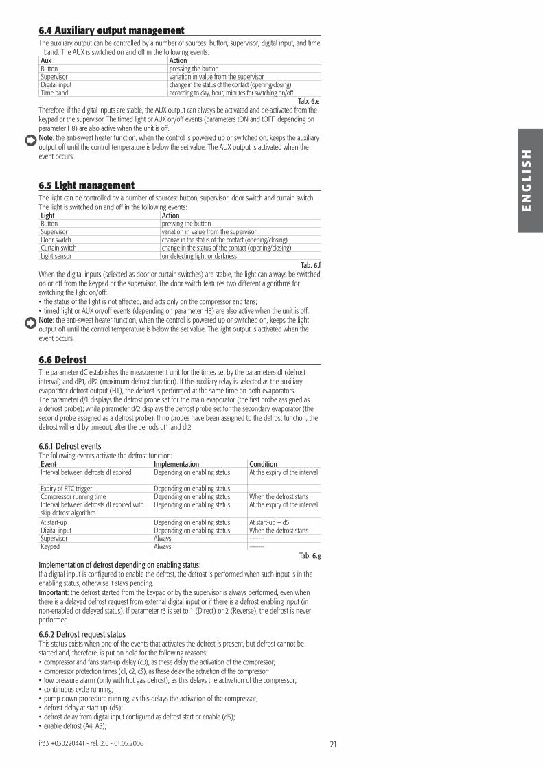
6.4 Auxiliary output managementThe auxiliary output can be controlled by a number of sources: button, supervisor, digital input, and time
band. The AUX is switched on and off in the following events:Aux ActionButton pressing the buttonSupervisor variation in value from the supervisorDigital input change in the status of the contact (opening/closing)Time band according to day, hour, minutes for switching on/off
Tab. 6.eTherefore, if the digital inputs are stable, the AUX output can always be activated and de-activated from the keypad or the supervisor. The timed light or AUX on/off events (parameters tON and tOFF, depending on parameter H8) are also active when the unit is off.Note: the anti-sweat heater function, when the control is powered up or switched on, keeps the auxiliary output off until the control temperature is below the set value. The AUX output is activated when the event occurs.
6.5 Light managementThe light can be controlled by a number of sources: button, supervisor, door switch and curtain switch. The light is switched on and off in the following events:Light ActionButton pressing the buttonSupervisor variation in value from the supervisorDoor switch change in the status of the contact (opening/closing)Curtain switch change in the status of the contact (opening/closing)Light sensor on detecting light or darkness
Tab. 6.fWhen the digital inputs (selected as door or curtain switches) are stable, the light can always be switched on or off from the keypad or the supervisor. The door switch features two different algorithms for switching the light on/off:• the status of the light is not affected, and acts only on the compressor and fans;• timed light or AUX on/off events (depending on parameter H8) are also active when the unit is off.Note: the anti-sweat heater function, when the control is powered up or switched on, keeps the light output off until the control temperature is below the set value. The light output is activated when the event occurs.
6.6 DefrostThe parameter dC establishes the measurement unit for the times set by the parameters dI (defrost interval) and dP1, dP2 (maximum defrost duration). If the auxiliary relay is selected as the auxiliary evaporator defrost output (H1), the defrost is performed at the same time on both evaporators. The parameter d/1 displays the defrost probe set for the main evaporator (the fi rst probe assigned as a defrost probe); while parameter d/2 displays the defrost probe set for the secondary evaporator (the second probe assigned as a defrost probe). If no probes have been assigned to the defrost function, the defrost will end by timeout, after the periods dt1 and dt2.
6.6.1 Defrost eventsThe following events activate the defrost function:Event Implementation ConditionInterval between defrosts dI expired Depending on enabling status At the expiry of the interval
Expiry of RTC trigger Depending on enabling status -------Compressor running time Depending on enabling status When the defrost startsInterval between defrosts dI expired with skip defrost algorithm
Depending on enabling status At the expiry of the interval
At start-up Depending on enabling status At start-up + d5Digital input Depending on enabling status When the defrost startsSupervisor Always --------Keypad Always --------
Tab. 6.gImplementation of defrost depending on enabling status:If a digital input is confi gured to enable the defrost, the defrost is performed when such input is in the enabling status, otherwise it stays pending.Important: the defrost started from the keypad or by the supervisor is always performed, even when there is a delayed defrost request from external digital input or if there is a defrost enabling input (in non-enabled or delayed status). If parameter r3 is set to 1 (Direct) or 2 (Reverse), the defrost is never performed.
6.6.2 Defrost request statusThis status exists when one of the events that activates the defrost is present, but defrost cannot be started and, therefore, is put on hold for the following reasons:• compressor and fans start-up delay (c0), as these delay the activation of the compressor;• compressor protection times (c1, c2, c3), as these delay the activation of the compressor;• low pressure alarm (only with hot gas defrost), as this delays the activation of the compressor;• continuous cycle running;• pump down procedure running, as this delays the activation of the compressor;• defrost delay at start-up (d5);• defrost delay from digital input confi gured as defrost start or enable (d5);• enable defrost (A4, A5);
22
EN
GL
ISH
ir33 +030220441 - rel. 2.0 - 01.05.2006
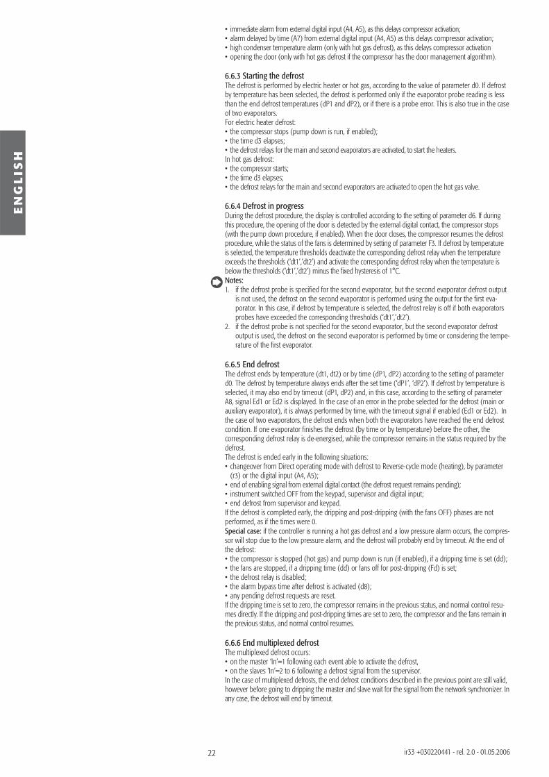
• immediate alarm from external digital input (A4, A5), as this delays compressor activation;• alarm delayed by time (A7) from external digital input (A4, A5) as this delays compressor activation;• high condenser temperature alarm (only with hot gas defrost), as this delays compressor activation• opening the door (only with hot gas defrost if the compressor has the door management algorithm).
6.6.3 Starting the defrostThe defrost is performed by electric heater or hot gas, according to the value of parameter d0. If defrost by temperature has been selected, the defrost is performed only if the evaporator probe reading is less than the end defrost temperatures (dP1 and dP2), or if there is a probe error. This is also true in the case of two evaporators.For electric heater defrost:• the compressor stops (pump down is run, if enabled);• the time d3 elapses;• the defrost relays for the main and second evaporators are activated, to start the heaters.In hot gas defrost:• the compressor starts;• the time d3 elapses;• the defrost relays for the main and second evaporators are activated to open the hot gas valve.
6.6.4 Defrost in progressDuring the defrost procedure, the display is controlled according to the setting of parameter d6. If during this procedure, the opening of the door is detected by the external digital contact, the compressor stops (with the pump down procedure, if enabled). When the door closes, the compressor resumes the defrost procedure, while the status of the fans is determined by setting of parameter F3. If defrost by temperature is selected, the temperature thresholds deactivate the corresponding defrost relay when the temperature exceeds the thresholds (‘dt1’,’dt2’) and activate the corresponding defrost relay when the temperature is below the thresholds (‘dt1’,’dt2’) minus the fi xed hysteresis of 1°C.Notes:1. if the defrost probe is specifi ed for the second evaporator, but the second evaporator defrost output
is not used, the defrost on the second evaporator is performed using the output for the fi rst eva-porator. In this case, if defrost by temperature is selected, the defrost relay is off if both evaporators probes have exceeded the corresponding thresholds (‘dt1’,’dt2’).
2. if the defrost probe is not specifi ed for the second evaporator, but the second evaporator defrost output is used, the defrost on the second evaporator is performed by time or considering the tempe-rature of the fi rst evaporator.
6.6.5 End defrostThe defrost ends by temperature (dt1, dt2) or by time (dP1, dP2) according to the setting of parameter d0. The defrost by temperature always ends after the set time (‘dP1’, ‘dP2’). If defrost by temperature is selected, it may also end by timeout (dP1, dP2) and, in this case, according to the setting of parameter A8, signal Ed1 or Ed2 is displayed. In the case of an error in the probe selected for the defrost (main or auxiliary evaporator), it is always performed by time, with the timeout signal if enabled (Ed1 or Ed2). In the case of two evaporators, the defrost ends when both the evaporators have reached the end defrost condition. If one evaporator fi nishes the defrost (by time or by temperature) before the other, the corresponding defrost relay is de-energised, while the compressor remains in the status required by the defrost.The defrost is ended early in the following situations:• changeover from Direct operating mode with defrost to Reverse-cycle mode (heating), by parameter
(r3) or the digital input (A4, A5);• end of enabling signal from external digital contact (the defrost request remains pending);• instrument switched OFF from the keypad, supervisor and digital input;• end defrost from supervisor and keypad.If the defrost is completed early, the dripping and post-dripping (with the fans OFF) phases are not performed, as if the times were 0.Special case: if the controller is running a hot gas defrost and a low pressure alarm occurs, the compres-sor will stop due to the low pressure alarm, and the defrost will probably end by timeout. At the end of the defrost:• the compressor is stopped (hot gas) and pump down is run (if enabled), if a dripping time is set (dd);• the fans are stopped, if a dripping time (dd) or fans off for post-dripping (Fd) is set;• the defrost relay is disabled;• the alarm bypass time after defrost is activated (d8);• any pending defrost requests are reset.If the dripping time is set to zero, the compressor remains in the previous status, and normal control resu-mes directly. If the dripping and post-dripping times are set to zero, the compressor and the fans remain in the previous status, and normal control resumes.
6.6.6 End multiplexed defrostThe multiplexed defrost occurs:• on the master ‘In’=1 following each event able to activate the defrost, • on the slaves ‘In’=2 to 6 following a defrost signal from the supervisor.In the case of multiplexed defrosts, the end defrost conditions described in the previous point are still valid, however before going to dripping the master and slave wait for the signal from the network synchronizer. In any case, the defrost will end by timeout.
23
EN
GL
ISH
ir33 +030220441 - rel. 2.0 - 01.05.2006
6.6.7 DrippingThe dripping time is set by parameter dd, when the compressor is OFF and the fans are OFF. At the end of dripping time, the post-dripping phase starts with the fans OFF (Fd):• the compressor restarts normal operation;• the fans remain off.If the post-dripping time with fans OFF is set to zero, normal control is resumed directly.
Post-dripping (fans OFF)The post-dripping time with fans OFF is set by parameter Fd. At the end of the post-dripping time with the fans OFF, normal control resumes.
Notes on the defrost function• If defrost with RTC is selected, the parameter dI has no effect. In any case, the dI timer is updated and
the parameter becomes valid on all days only in the event of RTC alarms. The parameter dI should therefore be set for safety reasons.
• The timer used to determine the defrost interval dI is updated cyclically when reaching the end of the interval, thus enabling cyclical defrosts. The timer is also updated when the unit is OFF. If the timer dI expires when the unit is OFF, a defrost is performed when the unit is started. If an “RTC” or manual defrost is run from the keypad or the supervisor, the timer linked to dI is not reset at the start of the defrost. Consequently, at the end of defrost, the dI timer may expire, and another defrost may be performed. If a defrost is run from the digital input, with the compressor running time algorithm, or from the supervisor in Slave controllers, the timer dI is reset when the defrost request is generated. In this way, the defrost interval is a timeout for the generation of the defrost requests (used, for example, when the external timer is not working correctly). If defrost on start-up (d4) has been selected, and a defrost on start-up delay (d5) has been set, the timer dI must be set to the end of the defrost delay on start-up. For units programmed in the same way, and with the same value of ‘dI’ and different values of ‘d5’, this enables the defrosts at start-up to be distributed through time, and the time staggering of the defrosts to be maintained for the subsequent events too. If control with 2 compressor steps is selected (with or without rotation, H1 = 12 or 13) the hot gas defrost requires the activation of the 2 steps, while the heater defrost deactivates the steps.
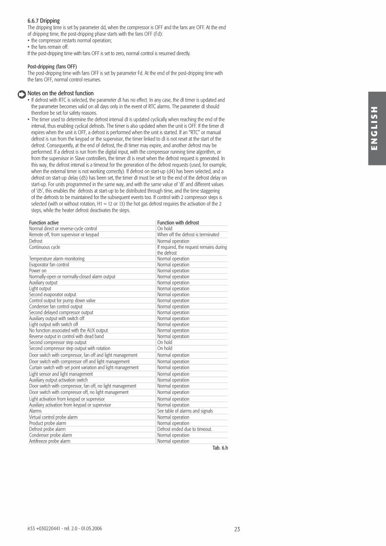
Function active Function with defrostNormal direct or reverse-cycle control On holdRemote off, from supervisor or keypad When off the defrost is terminatedDefrost Normal operationContinuous cycle If required, the request remains during
the defrostTemperature alarm monitoring Normal operationEvaporator fan control Normal operationPower on Normal operationNormally-open or normally-closed alarm output Normal operationAuxiliary output Normal operationLight output Normal operationSecond evaporator output Normal operationControl output for pump down valve Normal operationCondenser fan control output Normal operationSecond delayed compressor output Normal operationAuxiliary output with switch off Normal operationLight output with switch off Normal operationNo function associated with the AUX output Normal operationReverse output in control with dead band Normal operationSecond compressor step output On holdSecond compressor step output with rotation On holdDoor switch with compressor, fan off and light management Normal operationDoor switch with compressor off and light management Normal operationCurtain switch with set point variation and light management Normal operationLight sensor and light management Normal operationAuxiliary output activation switch Normal operationDoor switch with compressor, fan off, no light management Normal operationDoor switch with compressor off, no light management Normal operationLight activation from keypad or supervisor Normal operationAuxiliary activation from keypad or supervisor Normal operationAlarms See table of alarms and signalsVirtual control probe alarm Normal operationProduct probe alarm Normal operationDefrost probe alarm Defrost ended due to timeout.Condenser probe alarm Normal operationAntifreeze probe alarm Normal operation
Tab. 6.h
24
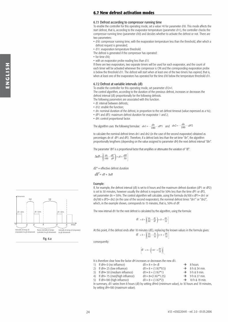
Sbrinamento
Intervallo di tempo dI (impostato) tra gli sbrinamenti
Nuovo intervallo di tempo (calcolato) tra gli sbrinamenti
Intervallo di tempo dI (impostato)tra gli sbrinamenti
dI dI1 dI2 dIdI
DdI DdI
tempo0
dE < dn% dE < dn% dE > dn%
Fig. 6.a
EN
GL
ISH
ir33 +030220441 - rel. 2.0 - 01.05.2006
6.7 New defrost activation modes
6.7.1 Defrost according to compressor running timeTo enable the controller for this operating mode, set a value >0 for parameter d10. This mode affects the start defrost, that is, according to the evaporator temperature (parameter d11), the controller checks the compressor running time (parameter d10) and decides whether to activate the defrost or not. There are two parameters:• d10: compressor running time, with the evaporation temperature less than the threshold, after which a
defrost request is generated;• d11: evaporation temperature threshold.The defrost is generated if the compressor has operated:• for time d10;• with an evaporator probe reading less than d11.If there are two evaporators, two separate timers will be used for each evaporator, and the count of each timer will be activated whenever the compressor is ON and the corresponding evaporation probe is below the threshold d11. The defrost will start when at least one of the two timers has expired, that is, when at least one of the evaporators has operated for the time d10 below the temperature threshold d11.
6.7.2 Defrost at variable intervals (dI)To enable the controller for this operating mode, set parameter d12=1.The control algorithm, according to the duration of the previous defrost, increases or decreases the defrost interval (dI) proportionally for the following defrosts. The following parameters are associated with this function. • dI: interval between defrosts;• d12: enable the function;• dn: nominal duration of the defrost, in proportion to the set defrost timeout (value expressed as a %);• dP1 and dP2: maximum defrost duration for evaporator 1 and 2;• dH: control proportional factor.
The algorithm uses the following formulae: dn1 dP1100dn and dn2 dP2
100dn
to calculate the nominal defrost times dn1 and dn2 (in the case of the second evaporator) obtained as percentages dn of dP1 and dP2. Therefore, if a defrost lasts less than the set time “dn”, the algorithm proportionally lengthens (depending on the value assigned to parameter dH) the next defrost interval “dIn”.
The parameter ‘dH’ is a proportional factor that amplifi es or attenuates the variation of “dI”:
∆dI dn100
dI dH50
dE*
dP
dE* = effective defrost duration
∆dIdIdI
n
Example:If, for example, the defrost interval (dI) is set to 8 hours and the maximum defrost duration (dP1 or dP2) is set to 30 minutes, however usually the defrost is required for 50% less than the time dP1 or dP2, set parameter dn = 50%. The control algorithm will calculate, using the formula dn/100 x dP1= dn1 or dn/100 x dP2= dn2 (in the case of the second evaporator), the nominal defrost times “dn1” or “dn2”, which, in the example shown, corresponds to 15 minutes, that is, 50% of dP.
The new interval dI1 for the next defrost is calculated by the algorithm, using the formula:
dI 1 dn
100dIdI + dH
50dEdP
At this point, if the defrost ends after 10 minutes (dE), replacing the known values in the formula gives:dI
1 50100
1030
8 8 dH50
consequently:
dI 1 1.1678 + dH
50.
It is therefore clear how the factor dH increases or decreases the new dI1.1) If dH= 0 (no infl uence) dI1= 8 + 0= dl 8 hours2) If dH= 25 (low infl uence) dI1= 8 + (1.167*0.5) 8 h & 34 min.3) If dH= 50 (medium infl uence) dI1= 8 + (1.167*1) 9 h & 9 min.4) If dH= 75 (med/high infl uence) dI1= 8+(1.167*1.25) 9 h & 27 min.5) If dH=100 (high infl uence) dI1= 8 + (1.167*2) 10 h & 19 min.In summary, dI1 varies from 8 hours (dI) by setting dH=0 (minimum value), to 10 hours and 19 minutes, by setting dH=100 (maximum value).
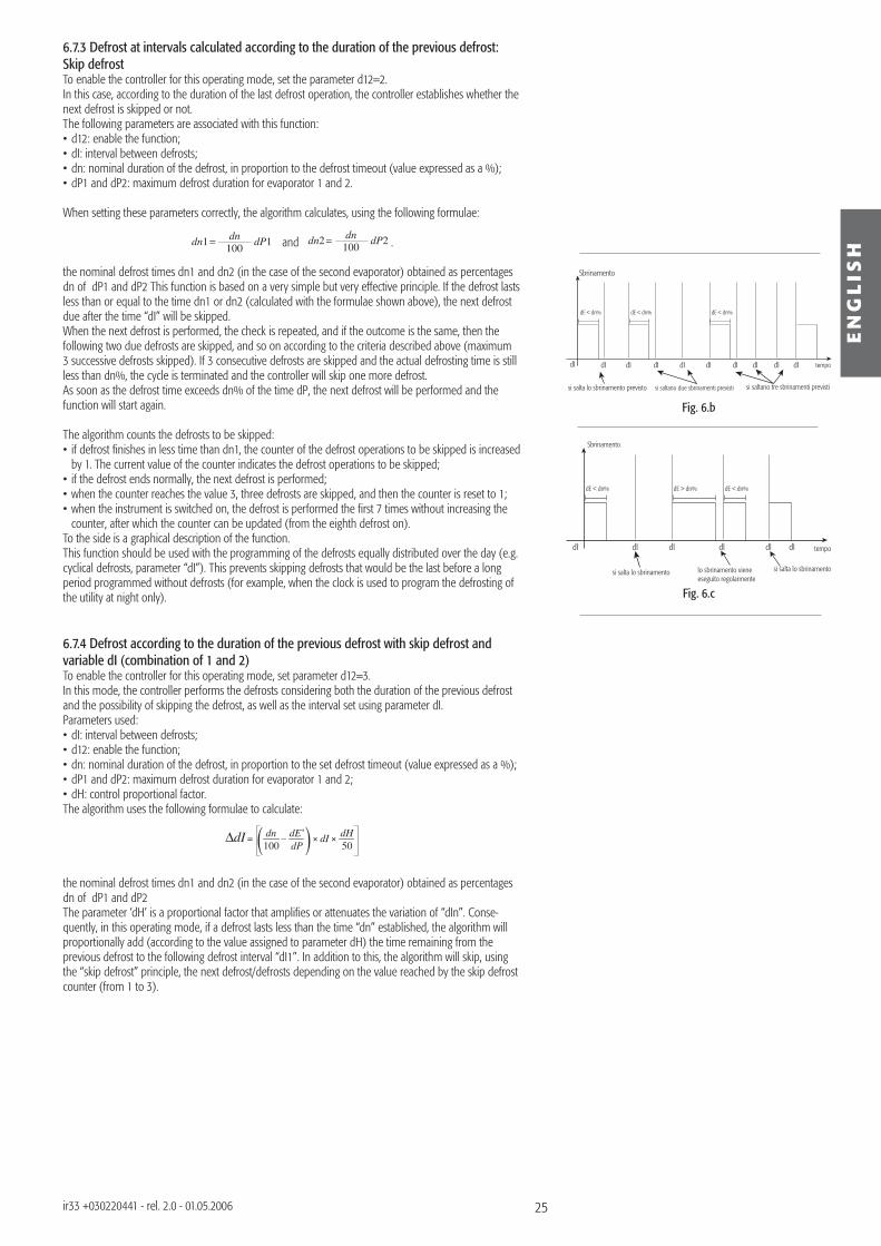
25
Sbrinamento
si salta lo sbrinamento previsto si saltano due sbrinamenti previsti si saltano tre sbrinamenti previsti
dI dI dI dI dI dI dI dIdI dI tempo
dE < dn% dE < dn% dE < dn%
Sbrinamento
si salta lo sbrinamento lo sbrinamento viene eseguito regolarmente
si salta lo sbrinamento
dI dI dI dIdI tempo
dE < dn% dE < dn%dE > dn%
dI
Fig. 6.b
Fig. 6.c
EN
GL
ISH
ir33 +030220441 - rel. 2.0 - 01.05.2006
6.7.3 Defrost at intervals calculated according to the duration of the previous defrost: Skip defrostTo enable the controller for this operating mode, set the parameter d12=2.In this case, according to the duration of the last defrost operation, the controller establishes whether the next defrost is skipped or not.The following parameters are associated with this function:• d12: enable the function;• dI: interval between defrosts;• dn: nominal duration of the defrost, in proportion to the defrost timeout (value expressed as a %);• dP1 and dP2: maximum defrost duration for evaporator 1 and 2.
When setting these parameters correctly, the algorithm calculates, using the following formulae:
dn1 dP1100dn and dn2 dP2
100dn
.
the nominal defrost times dn1 and dn2 (in the case of the second evaporator) obtained as percentages dn of dP1 and dP2 This function is based on a very simple but very effective principle. If the defrost lasts less than or equal to the time dn1 or dn2 (calculated with the formulae shown above), the next defrost due after the time “dI” will be skipped.When the next defrost is performed, the check is repeated, and if the outcome is the same, then the following two due defrosts are skipped, and so on according to the criteria described above (maximum 3 successive defrosts skipped). If 3 consecutive defrosts are skipped and the actual defrosting time is still less than dn%, the cycle is terminated and the controller will skip one more defrost.As soon as the defrost time exceeds dn% of the time dP, the next defrost will be performed and the function will start again.
The algorithm counts the defrosts to be skipped:• if defrost fi nishes in less time than dn1, the counter of the defrost operations to be skipped is increased
by 1. The current value of the counter indicates the defrost operations to be skipped;• if the defrost ends normally, the next defrost is performed;• when the counter reaches the value 3, three defrosts are skipped, and then the counter is reset to 1;• when the instrument is switched on, the defrost is performed the fi rst 7 times without increasing the
counter, after which the counter can be updated (from the eighth defrost on).To the side is a graphical description of the function.This function should be used with the programming of the defrosts equally distributed over the day (e.g. cyclical defrosts, parameter “dI”). This prevents skipping defrosts that would be the last before a long period programmed without defrosts (for example, when the clock is used to program the defrosting of the utility at night only).
6.7.4 Defrost according to the duration of the previous defrost with skip defrost and variable dI (combination of 1 and 2)To enable the controller for this operating mode, set parameter d12=3.In this mode, the controller performs the defrosts considering both the duration of the previous defrost and the possibility of skipping the defrost, as well as the interval set using parameter dI.Parameters used:• dI: interval between defrosts;• d12: enable the function;• dn: nominal duration of the defrost, in proportion to the set defrost timeout (value expressed as a %);• dP1 and dP2: maximum defrost duration for evaporator 1 and 2;• dH: control proportional factor.The algorithm uses the following formulae to calculate:
∆dI dn
100dI dH
50dE*
dP
the nominal defrost times dn1 and dn2 (in the case of the second evaporator) obtained as percentages dn of dP1 and dP2The parameter ‘dH’ is a proportional factor that amplifi es or attenuates the variation of “dIn”. Conse-quently, in this operating mode, if a defrost lasts less than the time “dn” established, the algorithm will proportionally add (according to the value assigned to parameter dH) the time remaining from the previous defrost to the following defrost interval “dI1”. In addition to this, the algorithm will skip, using the “skip defrost” principle, the next defrost/defrosts depending on the value reached by the skip defrost counter (from 1 to 3).
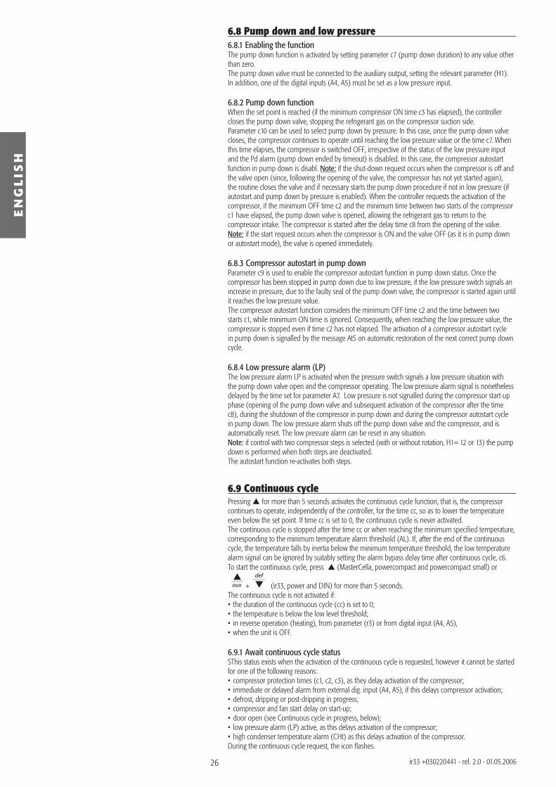
26
EN
GL
ISH
ir33 +030220441 - rel. 2.0 - 01.05.2006
6.8 Pump down and low pressure6.8.1 Enabling the functionThe pump down function is activated by setting parameter c7 (pump down duration) to any value other than zero.The pump down valve must be connected to the auxiliary output, setting the relevant parameter (H1). In addition, one of the digital inputs (A4, A5) must be set as a low pressure input.
6.8.2 Pump down functionWhen the set point is reached (if the minimum compressor ON time c3 has elapsed), the controller closes the pump down valve, stopping the refrigerant gas on the compressor suction side.Parameter c10 can be used to select pump down by pressure. In this case, once the pump down valve closes, the compressor continues to operate until reaching the low pressure value or the time c7. When this time elapses, the compressor is switched OFF, irrespective of the status of the low pressure input and the Pd alarm (pump down ended by timeout) is disabled. In this case, the compressor autostart function in pump down is disabl. Note: if the shut-down request occurs when the compressor is off and the valve open (since, following the opening of the valve, the compressor has not yet started again), the routine closes the valve and if necessary starts the pump down procedure if not in low pressure (if autostart and pump down by pressure is enabled). When the controller requests the activation of the compressor, if the minimum OFF time c2 and the minimum time between two starts of the compressor c1 have elapsed, the pump down valve is opened, allowing the refrigerant gas to return to the compressor intake. The compressor is started after the delay time c8 from the opening of the valve. Note: if the start request occurs when the compressor is ON and the valve OFF (as it is in pump down or autostart mode), the valve is opened immediately.
6.8.3 Compressor autostart in pump downParameter c9 is used to enable the compressor autostart function in pump down status. Once the compressor has been stopped in pump down due to low pressure, if the low pressure switch signals an increase in pressure, due to the faulty seal of the pump down valve, the compressor is started again until it reaches the low pressure value.The compressor autostart function considers the minimum OFF time c2 and the time between two starts c1, while minimum ON time is ignored. Consequently, when reaching the low pressure value, the compressor is stopped even if time c2 has not elapsed. The activation of a compressor autostart cycle in pump down is signalled by the message AtS on automatic restoration of the next correct pump down cycle.
6.8.4 Low pressure alarm (LP)The low pressure alarm LP is activated when the pressure switch signals a low pressure situation with the pump down valve open and the compressor operating. The low pressure alarm signal is nonetheless delayed by the time set for parameter A7. Low pressure is not signalled during the compressor start-up phase (opening of the pump down valve and subsequent activation of the compressor after the time c8), during the shutdown of the compressor in pump down and during the compressor autostart cycle in pump down. The low pressure alarm shuts off the pump down valve and the compressor, and is automatically reset. The low pressure alarm can be reset in any situation.Note: if control with two compressor steps is selected (with or without rotation, H1= 12 or 13) the pump down is performed when both steps are deactivated.The autostart function re-activates both steps.
6.9 Continuous cyclePressing for more than 5 seconds activates the continuous cycle function, that is, the compressor continues to operate, independently of the controller, for the time cc, so as to lower the temperature even below the set point. If time cc is set to 0, the continuous cycle is never activated.The continuous cycle is stopped after the time cc or when reaching the minimum specifi ed temperature, corresponding to the minimum temperature alarm threshold (AL). If, after the end of the continuous cycle, the temperature falls by inertia below the minimum temperature threshold, the low temperature alarm signal can be ignored by suitably setting the alarm bypass delay time after continuous cycle, c6.To start the continuous cycle, press (MasterCella, powercompact and powercompact small) or
aux + def
(ir33, power and DIN) for more than 5 seconds. The continuous cycle is not activated if:• the duration of the continuous cycle (cc) is set to 0;• the temperature is below the low level threshold;• in reverse operation (heating), from parameter (r3) or from digital input (A4, A5),• when the unit is OFF.
6.9.1 Await continuous cycle statusSThis status exists when the activation of the continuous cycle is requested, however it cannot be started for one of the following reasons:• compressor protection times (c1, c2, c3), as they delay activation of the compressor;• immediate or delayed alarm from external dig. input (A4, A5), if this delays compressor activation;• defrost, dripping or post-dripping in progress;• compressor and fan start delay on start-up;• door open (see Continuous cycle in progress, below);• low pressure alarm (LP) active, as this delays activation of the compressor;• high condenser temperature alarm (CHt) as this delays activation of the compressor.During the continuous cycle request, the icon fl ashes.
27
EN
GL
ISH
ir33 +030220441 - rel. 2.0 - 01.05.2006
6.9.2 Continuous cycle in progressWhen the continuous cycle is running:• the compressor is always ON;• the low temperature alarm is deactivated;• the icon is on steady.If, during the continuous cycle, the door is opened and one of the digital inputs is set to manage the opening of the door, the compressor stops and consequently the continuous cycle is temporarily interrupted.When the door closes the continuous cycle starts from where it left off, and thus ,in practice, the continuous cycle duration timer (cc) is put on hold when the door is opened, and starts again when the door closes. 6.9.3 End of the continuous cycleThe continuous cycle ends in the following ways:
• pressing (MasterCella, powercompact and powercompact small) or aux + def
(ir33, power and DIN) for more than 5 seconds;
• minimum specifi ed temperature (AL) reached;• maximum duration of the continuous cycle (cc) reached;• instrument switched off (OFF) from the keypad or supervisor;• changeover from Direct operating mode or Direct with defrost to Reverse-cycle mode (heating), by
parameter (r3) or the digital input (A4, A5).The low temperature alarm is bypassed for a time (c6) from the end of the continuous cycle.
Note: if control with 2 compressor steps is selected (with or without rotation, H1= 12 or 13) the conti-nuous cycle activates both steps.
Function active Function with continuous cycleNormal direct or reverse-cycle control On holdRemote off, from supervisor or keypad When off, the continuous cycle endsDefrost If necessary, the request remains during
the continuous cycleContinuous cycle Normal operationTemperature alarm monitoring Normal operationEvaporator fan control Normal operationPower on Normal operationNormally-open or normally-closed alarm output Normal operationAuxiliary output Normal operationLight output Normal operationSecond evaporator output Normal operationControl output for pump down valve Normal operationCondenser fan control output Normal operationSecond delayed compressor output Normal operationAuxiliary output with switch off Normal operationLight output with switch off Normal operationNo function associated with the AUX output Normal operationReverse output in control with dead band Normal operationSecond compressor step output ActivatedSecond compressor step output with rotation ActivatedDoor switch with compressor, fan off and light management Normal operationDoor switch with compressor off and light management Normal operationCurtain switch with set point variation and light management Normal operationLight sensor and light management Normal operationAuxiliary output activation switch Normal operationDoor switch with compressor, fan off, no light management Normal operationDoor switch with compressor off, no light management Normal operationLight activation from keypad or supervisor Normal operationAuxiliary activation from keypad or supervisor Normal operationAlarms See table of alarms and signalsVirtual control probe alarm Normal operationProduct probe alarm Normal operationDefrost probe alarm Normal operationCondenser probe alarm Normal operationAntifreeze probe alarm Normal operation
Tab. 6.g
28
EN
GL
ISH
ir33 +030220441 - rel. 2.0 - 01.05.2006
6.10 High condensing temperature alarmIf a probe is set as a condenser probe (/A2, /A3, /A4, /A5), the condensing temperature can be monitored and a high temperature condition signalled, probably due to situations of fouling and obstruction. If no condenser probe is selected, the condenser pre-alarm and alarm are disabled. The condenser fan output, if selected, is always OFF.If two condenser probes are selected, the high condenser temperature pre-alarm and alarm manage-ment algorithms are performed with reference to the probe with the higher value.The alarm status on one of the two condenser probes activates alarm management, ignoring the value of the other probe.The condenser high temperature threshold can be set with the parameter Ac and with a hysteresis used for activating the high condenser temperature alarm and for controlling the condensation fans by parameter AE. If the condenser temperature is > ‘Ac’+ (‘AE’/2), the pre-alarm is signalled, and there is no modifi cation to the status of the loads, but the display simply shows message ‘cht’. If in the pre-alarm situation the condenser temperature falls to <‘Ac’, the pre-alarm ends and the signal ‘cht’ is cancelled. If the condenser temperature is > ‘Ac’, the alarm delay timer is started (this can be set using the parameter ‘Acd’). If, at the end of delay ‘Acd’, the temperature is still above the threshold ‘Ac’, the alarm ‘CHt’ is activated, the message ‘CHt’ is shown on the display and the compressor is stopped, without observing the safety times (‘c1’, ‘c2’, ‘c3’). Alarm ‘CHt’ is manual reset only.If, on the other hand, the temperature returns below the threshold, the timer is reset and the pre-alarm status or normal operation resumes.The auxiliary relays can be set as condenser fan outputs (‘H1’), which are activated if the condenser temperature is > ‘F4’ + ‘F5’ and are deactivated if the condenser temperature is < ‘F4’. If two condenser probes are selected, the high condenser temperature pre-alarm and alarm management algorithms are performed with reference to the probe with the higher value.The alarm status on one of the two condenser probes activates alarm management, ignoring the value of the other probe.In the event of a condenser probe error, the pre-alarm cht and the alarm CHt are generated automatically.In the above situation, any auxiliary outputs confi gured accordingly are activated.
Condenser probe Pre-alarm Alarm Condenser fan outputs selectedNot present Not generated Not generated OFFTwo probes On probe with higher value On probe with higher value On probe with higher valueError (one of the probes) Generated Generated ON
Tab. 6.h
Function active Function with condenser fan controlNormal direct or reverse-cycle control Normal operationRemote off, from supervisor or keypad Condenser outputs deactivated, condenser pre-alarm and alarm resetDefrost Normal operationContinuous cycle Normal operationTemperature alarm monitoring Normal operationEvaporator fan control Normal operationPower on Normal operationNormally-open or normally-closed alarm output Normal operationAuxiliary output Normal operationLight output Normal operationSecond evaporator output Normal operationControl output for pump down valve Normal operationCondenser fan control output Normal operationSecond delayed compressor output Normal operationAuxiliary output with switch off Normal operationLight output with switch off Normal operationNo function associated with the AUX output Normal operationReverse output in control with dead band Normal operationSecond compressor step output Normal operationSecond compressor step output with rotation Normal operationDoor switch with compressor, fan off and light management Normal operationDoor switch with compressor off and light management Normal operationCurtain switch with set point variation and light management Normal operationLight sensor and light management Normal operationAuxiliary output activation switch Normal operationDoor switch with compressor, fan off, no light management Normal operationDoor switch with compressor off, no light management Normal operationLight activation from keypad or supervisor Normal operationAuxiliary activation from keypad or supervisor Normal operationAlarms See table of alarms and signalsVirtual control probe alarm Normal operationProduct probe alarm Normal operationDefrost probe alarm Normal operationCondenser probe alarm Condenser output on, condenser pre-alarm and alarm generated.Antifreeze probe alarm Normal operation
Tab. 6.i
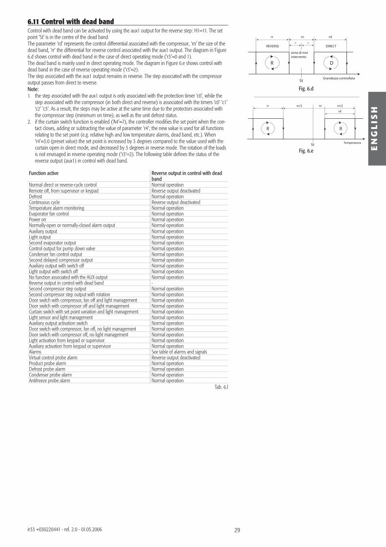
29
StGrandezza controllata
R
REVERSE
rr rn rd
D
DIRECT
zona di nonintervento
= =
St Temperatura
R
rr
rd
rnrn/2 rn/2
R
EN
GL
ISH
ir33 +030220441 - rel. 2.0 - 01.05.2006
Fig. 6.d
Fig. 6.e
6.11 Control with dead bandControl with dead band can be activated by using the aux1 output for the reverse step: H1=11. The set point ‘St’ is in the centre of the dead band.The parameter ‘rd’ represents the control differential associated with the compressor, ‘rn’ the size of the dead band, ‘rr’ the differential for reverse control associated with the aux1 output. The diagram in Figure 6.d shows control with dead band in the case of direct operating mode (‘r3’=0 and 1).The dead band is mainly used in direct operating mode. The diagram in Figure 6.e shows control with dead band in the case of reverse operating mode (‘r3’=2).The step associated with the aux1 output remains in reverse. The step associated with the compressor output passes from direct to reverse.Note: 1. the step associated with the aux1 output is only associated with the protection timer ‘c0’, while the
step associated with the compressor (in both direct and reverse) is associated with the timers ‘c0’ ‘c1’ ‘c2’ ‘c3’. As a result, the steps may be active at the same time due to the protectors associated with the compressor step (minimum on time), as well as the unit defrost status.
2. if the curtain switch function is enabled (‘A4’=7), the controller modifi es the set point when the con-tact closes, adding or subtracting the value of parameter ‘r4’; the new value is used for all functions relating to the set point (e.g. relative high and low temperature alarms, dead band, etc.). When ‘r4’=3.0 (preset value) the set point is increased by 3 degrees compared to the value used with the curtain open in direct mode, and decreased by 3 degrees in reverse mode. The rotation of the loads is not envisaged in reverse operating mode (‘r3’=2). The following table defi nes the status of the reverse output (aux1) in control with dead band.
Function active Reverse output in control with dead band
Normal direct or reverse-cycle control Normal operationRemote off, from supervisor or keypad Reverse output deactivatedDefrost Normal operationContinuous cycle Reverse output deactivatedTemperature alarm monitoring Normal operationEvaporator fan control Normal operationPower on Normal operationNormally-open or normally-closed alarm output Normal operationAuxiliary output Normal operationLight output Normal operationSecond evaporator output Normal operationControl output for pump down valve Normal operationCondenser fan control output Normal operationSecond delayed compressor output Normal operationAuxiliary output with switch off Normal operationLight output with switch off Normal operationNo function associated with the AUX output Normal operationReverse output in control with dead band -Second compressor step output Normal operationSecond compressor step output with rotation Normal operationDoor switch with compressor, fan off and light management Normal operationDoor switch with compressor off and light management Normal operationCurtain switch with set point variation and light management Normal operationLight sensor and light management Normal operationAuxiliary output activation switch Normal operationDoor switch with compressor, fan off, no light management Normal operationDoor switch with compressor off, no light management Normal operationLight activation from keypad or supervisor Normal operationAuxiliary activation from keypad or supervisor Normal operationAlarms See table of alarms and signalsVirtual control probe alarm Reverse output deactivatedProduct probe alarm Normal operationDefrost probe alarm Normal operationCondenser probe alarm Normal operationAntifreeze probe alarm Normal operation
Tab. 6.l
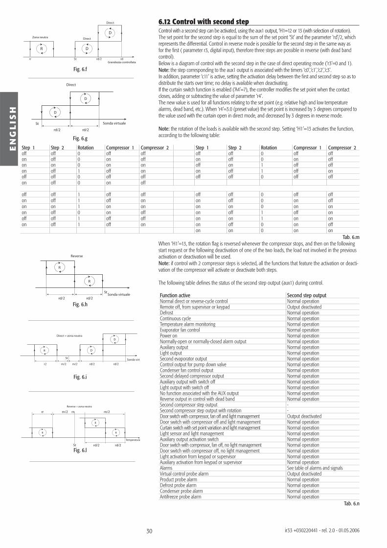
30
St
rd/2 rd/2Sonda virtuale
Reverse
R
R
St
r2
Sonda virtu
Direct + zona neutra
rd/2rd/2rn/2 rn/2
DR
D
St
rr rn/2 rn/2rn
Temperatura
rd/2rd/2
R
R
R
Reverse + zona neutra
St
rd/2 rd/2
Sonda virtuale
Direct
D
D
Zona neutra
rr St rd/2 rdGrandezza controllata
Direct
Direct
R D
D
EN
GL
ISH
ir33 +030220441 - rel. 2.0 - 01.05.2006
Fig. 6.g
Fig. 6.h
Fig. 6.i
Fig. 6.l
Fig. 6.f
6.12 Control with second stepControl with a second step can be activated, using the aux1 output, ‘H1=12 or 13 (with selection of rotation). The set point for the second step is equal to the sum of the set point ‘St’ and the parameter ‘rd’/2, which represents the differential. Control in reverse mode is possible for the second step in the same way as for the fi rst ( parameter r3, digital input), therefore three steps are possible in reverse (with dead band control).Below is a diagram of control with the second step in the case of direct operating mode (‘r3’=0 and 1).Note: the step corresponding to the aux1 output is associated with the timers ‘c0’,‘c1’,‘c2’,‘c3’.In addition, parameter ‘c11’ is active, setting the activation delay between the fi rst and second step so as to distribute the starts over time; no delay is available when deactivating.If the curtain switch function is enabled (‘A4’=7), the controller modifi es the set point when the contact closes, adding or subtracting the value of parameter ‘r4’.The new value is used for all functions relating to the set point (e.g. relative high and low temperature alarms, dead band, etc.). When ‘r4’=3.0 (preset value) the set point is increased by 3 degrees compared to the value used with the curtain open in direct mode, and decreased by 3 degrees in reverse mode.
Note: the rotation of the loads is available with the second step. Setting ‘H1’=13 activates the function, according to the following table:
Step 1 Step 2 Rotation Compressor 1 Compressor 2 Step 1 Step 2 Rotation Compressor 1 Compressor 2off off 0 off off off off 0 off offon off 0 on off on off 0 on offon on 0 on on off on 1 off offon off 1 off on on off 1 off onoff off 0 off off off off 0 off offon off 0 on off
off off 1 off off off off 0 off offon off 1 off on on off 0 on offon on 1 on on on on 0 on onon off 0 on off on off 1 off onoff off 1 off off on on 1 on onon off 1 off on on off 0 on off
on on 0 on onTab. 6.m
When ‘H1’=13, the rotation fl ag is reversed whenever the compressor stops, and then on the following start request or the following deactivation of one of the two loads, the load not involved in the previous activation or deactivation will be used.Note: if control with 2 compressor steps is selected, all the functions that feature the activation or deacti-vation of the compressor will activate or deactivate both steps.
The following table defi nes the status of the second step output (aux1) during control.
Function active Second step outputNormal direct or reverse-cycle control Normal operationRemote off, from supervisor or keypad Output deactivatedDefrost Normal operationContinuous cycle Normal operationTemperature alarm monitoring Normal operationEvaporator fan control Normal operationPower on Normal operationNormally-open or normally-closed alarm output Normal operationAuxiliary output Normal operationLight output Normal operationSecond evaporator output Normal operationControl output for pump down valve Normal operationCondenser fan control output Normal operationSecond delayed compressor output Normal operationAuxiliary output with switch off Normal operationLight output with switch off Normal operationNo function associated with the AUX output Normal operationReverse output in control with dead band Normal operationSecond compressor step output -Second compressor step output with rotation -Door switch with compressor, fan off and light management Output deactivatedDoor switch with compressor off and light management Normal operationCurtain switch with set point variation and light management Normal operationLight sensor and light management Normal operationAuxiliary output activation switch Normal operationDoor switch with compressor, fan off, no light management Normal operationDoor switch with compressor off, no light management Normal operationLight activation from keypad or supervisor Normal operationAuxiliary activation from keypad or supervisor Normal operationAlarms See table of alarms and signalsVirtual control probe alarm Output deactivatedProduct probe alarm Normal operationDefrost probe alarm Normal operationCondenser probe alarm Normal operationAntifreeze probe alarm Normal operation
Tab. 6.n
31
EN
GL
ISH
ir33 +030220441 - rel. 2.0 - 01.05.2006
6.13 Anti-sweat heater functionThe anti-sweat heater function is used to maintain the aux1 output, confi gured as the light or aux: (H1= 2, 3, 8, 9) deactivated while the control temperature (virtual probe) is less than ‘St’+‘Hdh’ when the instrument is fi rst powered up, the ‘HI’ ‘IA’ ‘dA ‘CHt’ ‘EE’ ‘EF’ ‘rE’ alarms are reset, or when switching on. During the aforementioned alarms, the aux1 output, confi gured as above, is deactivated. ‘Hdh’ represents the offset from the set point for the anti-sweat heater function. If ‘Hdh’=0, the anti-sweat heater function is disabled. Note: at the end of the anti-sweat heater function the outputs confi gured as the light or auxiliary can be controlled by the user using the keypad, the supervisor or the digital inputs.If the aux1 output is confi gured as light or auxiliary on power-up, it maintains the same status as prior to shutdown. If the anti-sweat heater function is enabled, this is no longer true: on power-up, the output remains off for the entire time that the function remains active. When the control temperature (virtual probe) reaches the value of ‘St’+‘Hdh’, the function ends, activating the light output and the auxiliary output, irrespective of their status prior to shutdown. Function active Function with anti-sweat heaterNormal direct or reverse-cycle control Normal operationRemote off, from supervisor or keypad Function restarted when switching onDefrost Normal operationContinuous cycle Normal operationTemperature alarm monitoring Normal operationEvaporator fan control Normal operationPower on Normal operationNormally-open or normally-closed alarm output Normal operationAuxiliary output Normal operationLight output Normal operationSecond evaporator output Normal operationControl output for pump down valve Normal operationCondenser fan control output Normal operationSecond delayed compressor output Normal operationAuxiliary output with switch off Normal operationLight output with switch off Normal operationNo function associated with the AUX output Normal operationReverse output in control with dead band Normal operationSecond compressor step output Normal operationSecond compressor step output with rotation Normal operationDoor switch with compressor, fan off and light management Normal operationDoor switch with compressor off and light management Normal operationCurtain switch with set point variation and light management Normal operationLight sensor and light management Normal operationAuxiliary output activation switch Normal operationDoor switch with compressor, fan off, no light management Normal operationDoor switch with compressor off, no light management Normal operationLight activation from keypad or supervisor Normal operationAuxiliary activation from keypad or supervisor Normal operationAlarms See table of alarms and signalsVirtual control probe alarm Function restarted.Product probe alarm Normal operationDefrost probe alarm Normal operationCondenser probe alarm Normal operationAntifreeze probe alarm Normal operation
Tab. 6.o
6.14 Antifreeze alarmThe antifreeze alarm is only active if a probe has been set as the antifreeze probe, /Ax = 4 (x=2-5).ALF defi nes the temperature value below which the antifreeze alarm AFr is activated, delayed by the time set for parameter AdF. The alarm is reset manually or from the supervisor. This condition involves the deactivation of the compressor and the activation of the alarm relay, if H1=0, 1.
Function active Function in antifreezeNormal direct or reverse-cycle control Normal operationRemote off, from supervisor or keypad Function disabled (timer restarted)Defrost Normal operationContinuous cycle Sospeso o pendenteTemperature alarm monitoring Normal operationEvaporator fan control Normal operationPower on Normal operationNormally-open or normally-closed alarm output Output energised with ‘AFr’Auxiliary output Normal operationLight output Normal operationSecond evaporator output Normal operationControl output for pump down valve Normal operationCondenser fan control output Normal operationSecond delayed compressor output Normal operationAuxiliary output with switch off Normal operationLight output with switch off Normal operationNo function associated with the AUX output Normal operationReverse output in control with dead band Normal operationSecond compressor step output Normal operationSecond compressor step output with rotation Normal operationDoor switch with compressor, fan off and light management Normal operationDoor switch with compressor off and light management Normal operationCurtain switch with set point variation and light management Normal operationLight sensor and light management Normal operationAuxiliary output activation switch Normal operation
32
EN
GL
ISH
ir33 +030220441 - rel. 2.0 - 01.05.2006
Function active Function in antifreezeDoor switch with compressor, fan off, no light management Normal operationDoor switch with compressor off, no light management Normal operationLight activation from keypad or supervisor Normal operationAuxiliary activation from keypad or supervisor Normal operationAlarms See table of alarms and signalsVirtual control probe alarm Normal operationProduct probe alarm Normal operationDefrost probe alarm Normal operationCondenser probe alarm Normal operationAntifreeze probe alarm Activation of ‘AFr’ alarm
Tab. 6.p
6.15 Special functions for the management of multiplexed cabinets (mpx)6.15.1 Multiplexed defrostThe multiplexed defrost allows the showcases belonging to the same sub-network to be defrosted in synch. As regards the instruments, the function is managed by a synchronizer that controls the start and the end of the defrost, as well as checking when all the controllers have reached the end (before the dripping phase). The master spontaneously starts the defrost (from any of the sources: RTC, keypad, supervisor, at intervals, …).The synchronizer detects the start of the defrost on the master and then activates it on the slaves.The master and slaves tell the synchronizer when they have reached the end defrost condition (before the dripping phase). The synchronizer sends a signal to all the units in the defrost status to end the procedure and pass to the dripping phase when all of them have reached the end defrost condition (including the end defrost by time out, parameter dP).Note: the synchronization of the multiplexed defrost is only activated in the Master and Slave controllers (‘In’=1 to 6).In the case of Slaves, the synchronization only takes place if the defrost has been started from the supervisor.
6.15.2 Remote alarm signalsThe alarm signals can be activated on other controllers in the system. This means that on each controller, the synchronizer can activate an alarm signal relating to another controller, using the symbol nx, where x may be between 1 and 6. Therefore, for example, if the controller with local network address 2 (slave 2) has an alarm, the signal n2 will be displayed on the controllers enabled.The parameter HSA enables the synchronizer to send the alarms to the controller from other devices in the local network. When displaying the remote alarms the alarm relay, if selected, is activated.Note: the synchronizer decides which alarms are signalled remotely.
6.15.3 Remote light and auxiliary outputThe light and aux relays on the master and on the slaves connected in the local network can be synchro-nized. The parameters ‘HrL’ and ‘HrA’ enable the synchronizer to send the status of the master light and the auxiliary relay, respectively. Note: the remote light and auxiliary function is managed by the synchronizer.
6.15.4 Downloading the parametersEntering parameter confi guration mode, with the current password + 44 (22 + 44 = 66), activates the download of the parameters. The download can be performed either from the master or from a slave in the local network. The controller that starts the function transfers its parameters to the other units. The synchronizer activates the message ‘dnL’ on all the controllers for the duration of the operation. In the event of errors when transferring the parameters, network errors, or errors saving the parameters to the controller, at the end of the download the synchronizer activates the corresponding error message (dx, x=1 to 6) to indicate that the download to unit x was not performed correctly.
Note: The parameters are downloaded by the network synchronizer, and thus this devices defi nes which parameters are transferred during the download.
Important: the parameters HrL, HrA, HsA and In are masked and therefore only visible using the programming kit (IROPZPRG00).
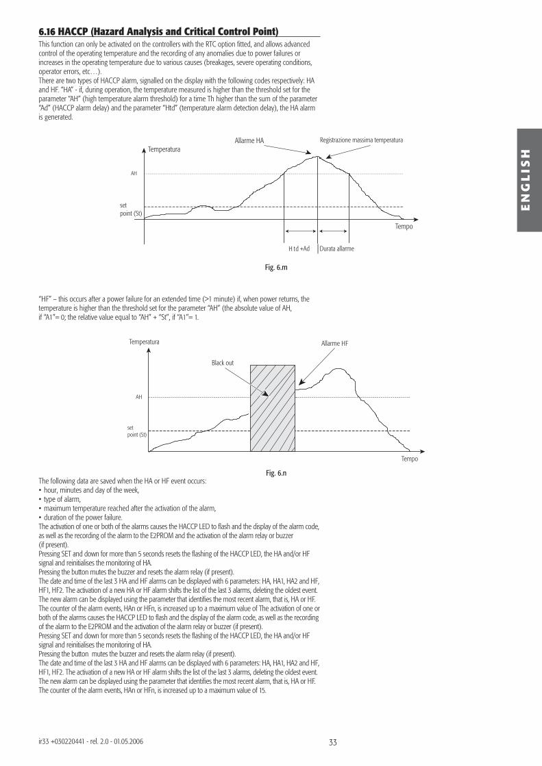
33
set point (St)
Registrazione massima temperatura
AH
H td +Ad
Allarme HA
Durata allarme
Temperatura
Tempo
set point (St)
AH
Black out
Allarme HF
Tempo
Temperatura
Fig. 6.m
Fig. 6.n
EN
GL
ISH
ir33 +030220441 - rel. 2.0 - 01.05.2006
6.16 HACCP (Hazard Analysis and Critical Control Point)This function can only be activated on the controllers with the RTC option fi tted, and allows advanced control of the operating temperature and the recording of any anomalies due to power failures or increases in the operating temperature due to various causes (breakages, severe operating conditions, operator errors, etc…).There are two types of HACCP alarm, signalled on the display with the following codes respectively: HA and HF. “HA” - if, during operation, the temperature measured is higher than the threshold set for the parameter “AH” (high temperature alarm threshold) for a time Th higher than the sum of the parameter “Ad” (HACCP alarm delay) and the parameter “Htd” (temperature alarm detection delay), the HA alarm is generated.
“HF” – this occurs after a power failure for an extended time (>1 minute) if, when power returns, the temperature is higher than the threshold set for the parameter “AH” (the absolute value of AH, if “A1”= 0; the relative value equal to “AH” + “St”, if “A1”= 1.
The following data are saved when the HA or HF event occurs:• hour, minutes and day of the week,• type of alarm,• maximum temperature reached after the activation of the alarm,• duration of the power failure.The activation of one or both of the alarms causes the HACCP LED to fl ash and the display of the alarm code, as well as the recording of the alarm to the E2PROM and the activation of the alarm relay or buzzer(if present).Pressing SET and down for more than 5 seconds resets the fl ashing of the HACCP LED, the HA and/or HF signal and reinitialises the monitoring of HA.Pressing the button mutes the buzzer and resets the alarm relay (if present).The date and time of the last 3 HA and HF alarms can be displayed with 6 parameters: HA, HA1, HA2 and HF, HF1, HF2. The activation of a new HA or HF alarm shifts the list of the last 3 alarms, deleting the oldest event. The new alarm can be displayed using the parameter that identifi es the most recent alarm, that is, HA or HF.The counter of the alarm events, HAn or HFn, is increased up to a maximum value of The activation of one or both of the alarms causes the HACCP LED to fl ash and the display of the alarm code, as well as the recording of the alarm to the E2PROM and the activation of the alarm relay or buzzer (if present).Pressing SET and down for more than 5 seconds resets the fl ashing of the HACCP LED, the HA and/or HF signal and reinitialises the monitoring of HA.Pressing the button mutes the buzzer and resets the alarm relay (if present).The date and time of the last 3 HA and HF alarms can be displayed with 6 parameters: HA, HA1, HA2 and HF, HF1, HF2. The activation of a new HA or HF alarm shifts the list of the last 3 alarms, deleting the oldest event. The new alarm can be displayed using the parameter that identifi es the most recent alarm, that is, HA or HF.The counter of the alarm events, HAn or HFn, is increased up to a maximum value of 15.
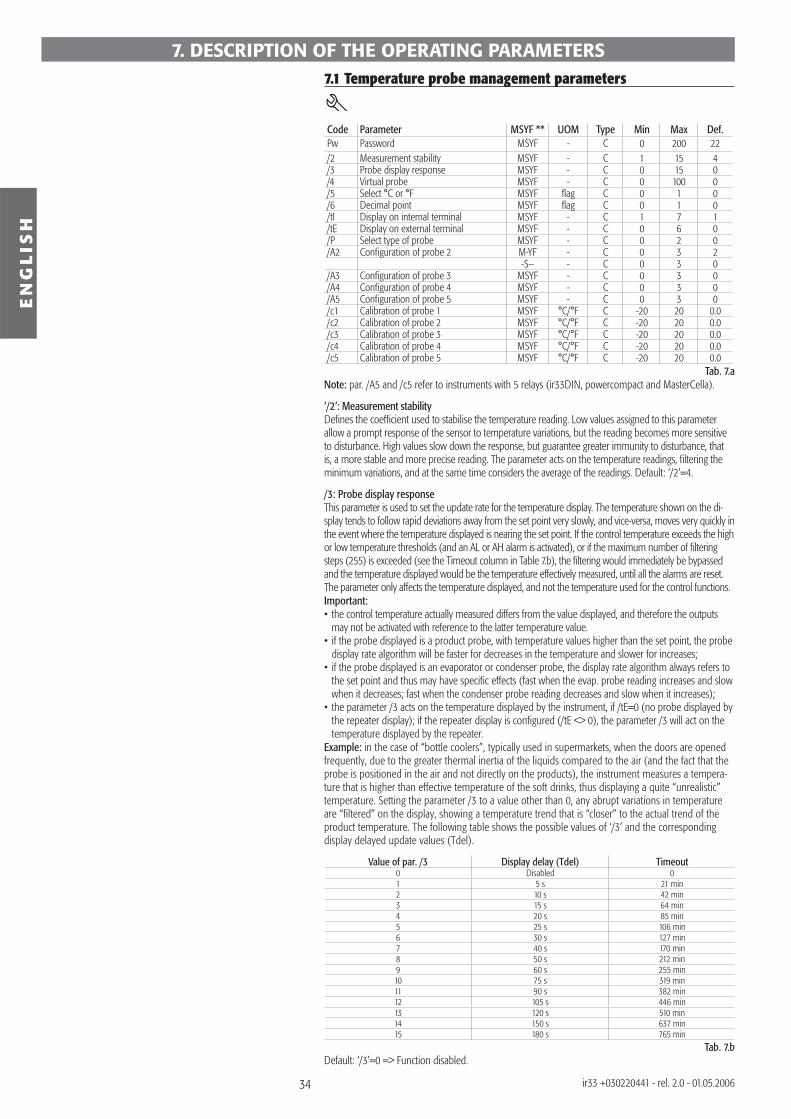
34
EN
GL
ISH
ir33 +030220441 - rel. 2.0 - 01.05.2006
7.1 Temperature probe management parameters
Code Parameter MSYF ** UOM Type Min Max Def.Pw Password MSYF - C 0 200 22/2 Measurement stability MSYF - C 1 15 4/3 Probe display response MSYF - C 0 15 0/4 Virtual probe MSYF - C 0 100 0/5 Select °C or °F MSYF fl ag C 0 1 0/6 Decimal point MSYF fl ag C 0 1 0/tI Display on internal terminal MSYF - C 1 7 1/tE Display on external terminal MSYF - C 0 6 0/P Select type of probe MSYF - C 0 2 0/A2 Confi guration of probe 2 M-YF - C 0 3 2
-S-- - C 0 3 0/A3 Confi guration of probe 3 MSYF - C 0 3 0/A4 Confi guration of probe 4 MSYF - C 0 3 0/A5 Confi guration of probe 5 MSYF - C 0 3 0/c1 Calibration of probe 1 MSYF °C/°F C -20 20 0.0/c2 Calibration of probe 2 MSYF °C/°F C -20 20 0.0/c3 Calibration of probe 3 MSYF °C/°F C -20 20 0.0/c4 Calibration of probe 4 MSYF °C/°F C -20 20 0.0/c5 Calibration of probe 5 MSYF °C/°F C -20 20 0.0
Tab. 7.aNote: par. /A5 and /c5 refer to instruments with 5 relays (ir33DIN, powercompact and MasterCella).
‘/2’: Measurement stabilityDefi nes the coeffi cient used to stabilise the temperature reading. Low values assigned to this parameter allow a prompt response of the sensor to temperature variations, but the reading becomes more sensitive to disturbance. High values slow down the response, but guarantee greater immunity to disturbance, that is, a more stable and more precise reading. The parameter acts on the temperature readings, fi ltering the minimum variations, and at the same time considers the average of the readings. Default: ‘/2’=4.
/3: Probe display responseThis parameter is used to set the update rate for the temperature display. The temperature shown on the di-splay tends to follow rapid deviations away from the set point very slowly, and vice-versa, moves very quickly in the event where the temperature displayed is nearing the set point. If the control temperature exceeds the high or low temperature thresholds (and an AL or AH alarm is activated), or if the maximum number of fi ltering steps (255) is exceeded (see the Timeout column in Table 7.b), the fi ltering would immediately be bypassed and the temperature displayed would be the temperature effectively measured, until all the alarms are reset. The parameter only affects the temperature displayed, and not the temperature used for the control functions.Important:• the control temperature actually measured differs from the value displayed, and therefore the outputs
may not be activated with reference to the latter temperature value.• if the probe displayed is a product probe, with temperature values higher than the set point, the probe
display rate algorithm will be faster for decreases in the temperature and slower for increases;• if the probe displayed is an evaporator or condenser probe, the display rate algorithm always refers to
the set point and thus may have specifi c effects (fast when the evap. probe reading increases and slow when it decreases; fast when the condenser probe reading decreases and slow when it increases);
• the parameter /3 acts on the temperature displayed by the instrument, if /tE=0 (no probe displayed by the repeater display); if the repeater display is confi gured (/tE <> 0), the parameter /3 will act on the temperature displayed by the repeater.
Example: in the case of “bottle coolers”, typically used in supermarkets, when the doors are opened frequently, due to the greater thermal inertia of the liquids compared to the air (and the fact that the probe is positioned in the air and not directly on the products), the instrument measures a tempera-ture that is higher than effective temperature of the soft drinks, thus displaying a quite “unrealistic” temperature. Setting the parameter /3 to a value other than 0, any abrupt variations in temperature are “fi ltered” on the display, showing a temperature trend that is “closer” to the actual trend of the product temperature. The following table shows the possible values of ‘/3’ and the corresponding display delayed update values (Tdel).
Value of par. /3 Display delay (Tdel) Timeout0 Disabled 01 5 s 21 min2 10 s 42 min3 15 s 64 min4 20 s 85 min5 25 s 106 min6 30 s 127 min7 40 s 170 min8 50 s 212 min9 60 s 255 min10 75 s 319 min11 90 s 382 min12 105 s 446 min13 120 s 510 min14 150 s 637 min15 180 s 765 min
Tab. 7.bDefault: ‘/3’=0 => Function disabled.
7. DESCRIPTION OF THE OPERATING PARAMETERS
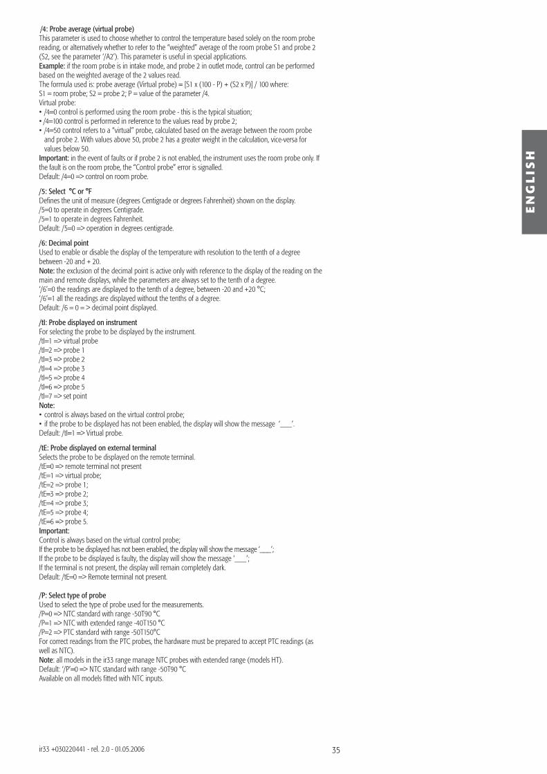
35
EN
GL
ISH
ir33 +030220441 - rel. 2.0 - 01.05.2006
/4: Probe average (virtual probe)This parameter is used to choose whether to control the temperature based solely on the room probe reading, or alternatively whether to refer to the “weighted” average of the room probe S1 and probe 2 (S2, see the parameter ‘/A2’). This parameter is useful in special applications.Example: if the room probe is in intake mode, and probe 2 in outlet mode, control can be performed based on the weighted average of the 2 values read.The formula used is: probe average (Virtual probe) = [S1 x (100 - P) + (S2 x P)] / 100 where:S1 = room probe; S2 = probe 2; P = value of the parameter /4.Virtual probe:• /4=0 control is performed using the room probe - this is the typical situation;• /4=100 control is performed in reference to the values read by probe 2;• /4=50 control refers to a “virtual” probe, calculated based on the average between the room probe
and probe 2. With values above 50, probe 2 has a greater weight in the calculation, vice-versa for values below 50.
Important: in the event of faults or if probe 2 is not enabled, the instrument uses the room probe only. If the fault is on the room probe, the “Control probe” error is signalled.Default: /4=0 => control on room probe.
/5: Select °C or °FDefi nes the unit of measure (degrees Centigrade or degrees Fahrenheit) shown on the display./5=0 to operate in degrees Centigrade./5=1 to operate in degrees Fahrenheit.Default: /5=0 => operation in degrees centigrade.
/6: Decimal pointUsed to enable or disable the display of the temperature with resolution to the tenth of a degree between -20 and + 20.Note: the exclusion of the decimal point is active only with reference to the display of the reading on the main and remote displays, while the parameters are always set to the tenth of a degree.‘/6’=0 the readings are displayed to the tenth of a degree, between -20 and +20 °C;‘/6’=1 all the readings are displayed without the tenths of a degree.Default: /6 = 0 = > decimal point displayed.
/tI: Probe displayed on instrumentFor selecting the probe to be displayed by the instrument./tI=1 => virtual probe/tI=2 => probe 1/tI=3 => probe 2/tI=4 => probe 3/tI=5 => probe 4/tI=6 => probe 5/tI=7 => set pointNote: • control is always based on the virtual control probe;• if the probe to be displayed has not been enabled, the display will show the message ‘___’.Default: /tI=1 => Virtual probe.
/tE: Probe displayed on external terminalSelects the probe to be displayed on the remote terminal./tE=0 => remote terminal not present/tE=1 => virtual probe;/tE=2 => probe 1;/tE=3 => probe 2;/tE=4 => probe 3;/tE=5 => probe 4;/tE=6 => probe 5.Important:Control is always based on the virtual control probe;If the probe to be displayed has not been enabled, the display will show the message ‘___’;If the probe to be displayed is faulty, the display will show the message ‘___’;If the terminal is not present, the display will remain completely dark.Default: /tE=0 => Remote terminal not present.
/P: Select type of probeUsed to select the type of probe used for the measurements./P=0 => NTC standard with range -50T90 °C/P=1 => NTC with extended range -40T150 °C/P=2 => PTC standard with range -50T150°CFor correct readings from the PTC probes, the hardware must be prepared to accept PTC readings (as well as NTC).Note: all models in the ir33 range manage NTC probes with extended range (models HT).Default: ‘/P’=0 => NTC standard with range -50T90 °CAvailable on all models fi tted with NTC inputs.
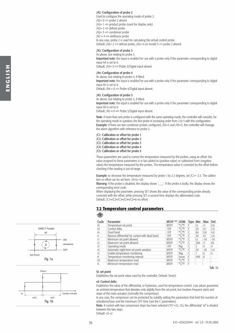
36
rd
Set Point
OFF
ON
DIRECT Freddo
attuatoreD
St
rd/2 rd/2
Sonda virtuale
Direct
EN
GL
ISH
ir33 +030220441 - rel. 2.0 - 01.05.2006
Fig. 7.b
Fig. 7.a
/A2: Confi guration of probe 2Used to confi gure the operating mode of probe 2./A2= 0 => probe 2 absent/A2= 1 => product probe (used for display only)/A2= 2 => defrost probe/A2= 3 => condenser probe/A2 = 4 => antifreeze probeIn any case, probe 2 is used for calculating the virtual control probe.Default: /A2= 2 => defrost probe; /A2= 0 on model S => probe 2 absent.
/A3: Confi guration of probe 3As above, but relating to probe 3. Important note: the input is enabled for use with a probe only if the parameter corresponding to digital input A4 is set to 0.Default: /A3= 0 => Probe 3/Digital input absent.
/A4: Confi guration of probe 4As above, but relating to probe 4, if fi tted. Important note: the input is enabled for use with a probe only if the parameter corresponding to digital input A5 is set to 0.Default: /A4 = 0 => Probe 4/Digital input absent.
/A5: Confi guration of probe 5 As above, but relating to probe 5, if fi tted.Important note: the input is enabled for use with a probe only if the parameter corresponding to digital input A9 is set to 0.Default: /A5 = 0 => Probe 5/Digital input absent.
Note: if more than one probe is confi gured with the same operating mode, the controller will consider, for the operating mode in question, the fi rst probe in increasing order from 2 to 5 with this confi guration.Example: if there are two condenser probes confi gured, /A3=3 and /A5=3, the controller will manage the alarm algorithm with reference to probe 3.
/C1: Calibration or offset for probe 1/C2: Calibration or offset for probe 2/C3: Calibration or offset for probe 3/C4: Calibration or offset for probe 4/C5: Calibration or offset for probe 5
These parameters are used to correct the temperature measured by the probes, using an offset: the value assigned to these parameters is in fact added to (positive value) or subtracted from (negative value) the temperature measured by the probes. The temperature value is corrected by the offset before checking if the reading is out-of-range.
Example: to decrease the temperature measured by probe 1 by 2.3 degrees, set /C1= -2.3. The calibra-tion or offset can be set from -20 to +20.Warning: if the probe is disabled, the display shows ‘___’. If the probe is faulty, the display shows the corresponding error code.When displaying the parameter, pressing SET shows the value of the corresponding probe already corrected with the offset, while pressing SET a second time displays the abbreviated code.Default: /C1=/C2=/C3=/C4=/C5=0 no offset.
7.2 Temperature control parameters
Code Parameter MSYF ** UOM Type Min Max Def.St Temperature set point MSYF °C/°F F r2 r1 0.0rd Control delta -SYF °C/°F F 20 0.1 2.0rn Dead band -SYF °C/°F C 60 0.0 4.0rr Reverse differential for control with dead band -SYF °C/°F C 20 0.1 2.0r1 Minimum set point allowed MSYF °C/°F C r2 -50 -50r2 Maximum set point allowed MSYF °C/°F C 200 r1 60r3 Operating mode -SYF fl ag C 2 0 0r4 Automatic night-time set point variation MSYF °C/°F C 20 -20 3.0r5 Enable temperature monitoring MSYF fl ag C 1 0 0rt Temperature monitoring interval MSYF hours F 999 0 -rH Maximum temperature read MSYF °C/°F F - - -rL Minimum temperature read MSYF °C/°F F - -
Tab. 7.cSt: set pointEstablishes the set point value used by the controller. Default: St=0.0.
rd: Control deltaEstablishes the value of the differential, or hysteresis, used for temperature control. Low values guarantee an ambient temperature that deviates only slightly from the set point, but involves frequent starts and stops of the main actuator (normally the compressor).In any case, the compressor can be protected by suitably setting the parameters that limit the number of activations/hour and the minimum OFF time (see the C parameters). Note: if control with two compressor steps has been selected (‘H1’=12, 13), the differential ‘rd’ is divided between the two steps.Default: rd =2
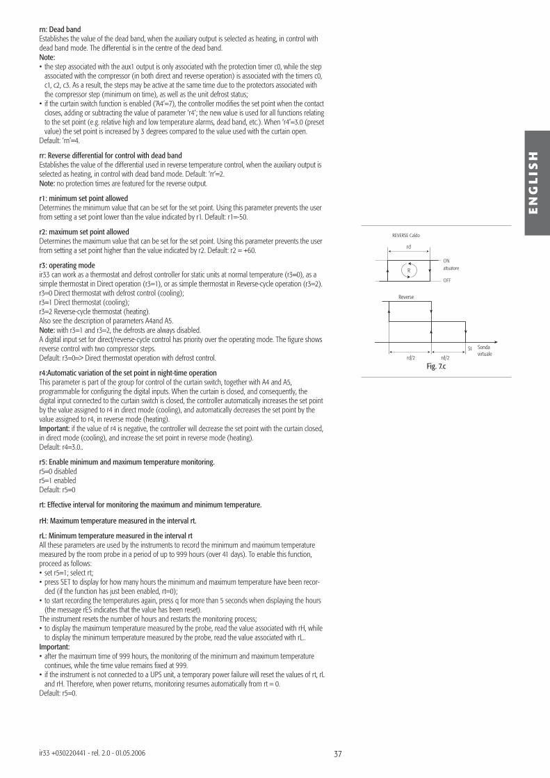
37
rd
OFF
ON
REVERSE Caldo
attuatoreR
St
rd/2 rd/2
Sonda virtuale
Reverse
Fig. 7.c
EN
GL
ISH
ir33 +030220441 - rel. 2.0 - 01.05.2006
rn: Dead bandEstablishes the value of the dead band, when the auxiliary output is selected as heating, in control with dead band mode. The differential is in the centre of the dead band.Note:• the step associated with the aux1 output is only associated with the protection timer c0, while the step
associated with the compressor (in both direct and reverse operation) is associated with the timers c0, c1, c2, c3. As a result, the steps may be active at the same time due to the protectors associated with the compressor step (minimum on time), as well as the unit defrost status;
• if the curtain switch function is enabled (‘A4’=7), the controller modifi es the set point when the contact closes, adding or subtracting the value of parameter ‘r4’; the new value is used for all functions relating to the set point (e.g. relative high and low temperature alarms, dead band, etc.). When ‘r4’=3.0 (preset value) the set point is increased by 3 degrees compared to the value used with the curtain open.
Default: ‘rn’=4.
rr: Reverse differential for control with dead bandEstablishes the value of the differential used in reverse temperature control, when the auxiliary output is selected as heating, in control with dead band mode. Default: ‘rr’=2.Note: no protection times are featured for the reverse output.
r1: minimum set point allowedDetermines the minimum value that can be set for the set point. Using this parameter prevents the user from setting a set point lower than the value indicated by r1. Default: r1=-50.
r2: maximum set point allowedDetermines the maximum value that can be set for the set point. Using this parameter prevents the user from setting a set point higher than the value indicated by r2. Default: r2 = +60.
r3: operating modeir33 can work as a thermostat and defrost controller for static units at normal temperature (r3=0), as a simple thermostat in Direct operation (r3=1), or as simple thermostat in Reverse-cycle operation (r3=2). r3=0 Direct thermostat with defrost control (cooling);r3=1 Direct thermostat (cooling);r3=2 Reverse-cycle thermostat (heating).Also see the description of parameters A4and A5.Note: with r3=1 and r3=2, the defrosts are always disabled.A digital input set for direct/reverse-cycle control has priority over the operating mode. The fi gure shows reverse control with two compressor steps.Default: r3=0=> Direct thermostat operation with defrost control.
r4:Automatic variation of the set point in night-time operationThis parameter is part of the group for control of the curtain switch, together with A4 and A5, programmable for confi guring the digital inputs. When the curtain is closed, and consequently, the digital input connected to the curtain switch is closed, the controller automatically increases the set point by the value assigned to r4 in direct mode (cooling), and automatically decreases the set point by the value assigned to r4, in reverse mode (heating).Important: if the value of r4 is negative, the controller will decrease the set point with the curtain closed, in direct mode (cooling), and increase the set point in reverse mode (heating).Default: r4=3.0..
r5: Enable minimum and maximum temperature monitoring.r5=0 disabledr5=1 enabledDefault: r5=0
rt: Effective interval for monitoring the maximum and minimum temperature.
rH: Maximum temperature measured in the interval rt.
rL: Minimum temperature measured in the interval rtAll these parameters are used by the instruments to record the minimum and maximum temperature measured by the room probe in a period of up to 999 hours (over 41 days). To enable this function, proceed as follows:• set r5=1; select rt;• press SET to display for how many hours the minimum and maximum temperature have been recor-
ded (if the function has just been enabled, rt=0);• to start recording the temperatures again, press q for more than 5 seconds when displaying the hours
(the message rES indicates that the value has been reset).The instrument resets the number of hours and restarts the monitoring process;• to display the maximum temperature measured by the probe, read the value associated with rH, while
to display the minimum temperature measured by the probe, read the value associated with rL..Important: • after the maximum time of 999 hours, the monitoring of the minimum and maximum temperature
continues, while the time value remains fi xed at 999.• if the instrument is not connected to a UPS unit, a temporary power failure will reset the values of rt, rL
and rH. Therefore, when power returns, monitoring resumes automatically from rt = 0.Default: r5=0.
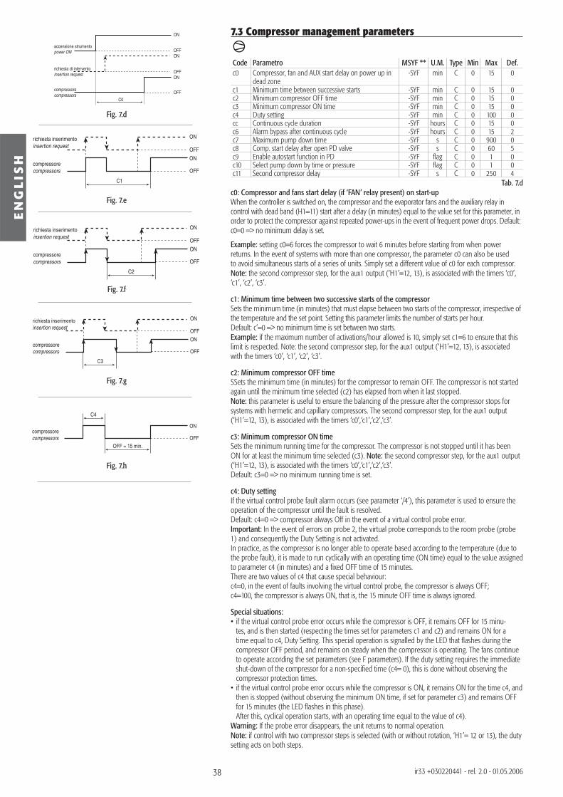
38
accensione strumento power ON
ON
ONOFF
ONOFF
OFF
C0
richiesta di interventoinsertion request
compressorecompressors
ON
ON
OFF
OFF
C1
richiesta inserimentoinsertion request
compressorecompressors
ON
ON
OFF
OFF
C2
richiesta inserimentoinsertion request
compressorecompressors
ON
ON
OFF
OFF
C3
richiesta inserimentoinsertion request
compressorecompressors
ON
OFF
C4
compressorecompressors
OFF = 15 min.
Fig. 7.d
Fig. 7.e
Fig. 7.f
Fig. 7.g
Fig. 7.h
EN
GL
ISH
ir33 +030220441 - rel. 2.0 - 01.05.2006
7.3 Compressor management parameters
Code Parametro MSYF ** U.M. Type Min Max Def.c0 Compressor, fan and AUX start delay on power up in
dead zone-SYF min C 0 15 0
c1 Minimum time between successive starts -SYF min C 0 15 0c2 Minimum compressor OFF time -SYF min C 0 15 0c3 Minimum compressor ON time -SYF min C 0 15 0c4 Duty setting -SYF min C 0 100 0cc Continuous cycle duration -SYF hours C 0 15 0c6 Alarm bypass after continuous cycle -SYF hours C 0 15 2c7 Maximum pump down time -SYF s C 0 900 0c8 Comp. start delay after open PD valve -SYF s C 0 60 5c9 Enable autostart function in PD -SYF fl ag C 0 1 0c10 Select pump down by time or pressure -SYF fl ag C 0 1 0c11 Second compressor delay -SYF s C 0 250 4
Tab. 7.dc0: Compressor and fans start delay (if ‘FAN’ relay present) on start-up When the controller is switched on, the compressor and the evaporator fans and the auxiliary relay in control with dead band (H1=11) start after a delay (in minutes) equal to the value set for this parameter, in order to protect the compressor against repeated power-ups in the event of frequent power drops. Default: c0=0 => no minimum delay is set.
Example: setting c0=6 forces the compressor to wait 6 minutes before starting from when power returns. In the event of systems with more than one compressor, the parameter c0 can also be used to avoid simultaneous starts of a series of units. Simply set a different value of c0 for each compressor. Note: the second compressor step, for the aux1 output (‘H1’=12, 13), is associated with the timers ‘c0’, ‘c1’, ‘c2’, ‘c3’.
c1: Minimum time between two successive starts of the compressorSets the minimum time (in minutes) that must elapse between two starts of the compressor, irrespective of the temperature and the set point. Setting this parameter limits the number of starts per hour. Default: c’=0 => no minimum time is set between two starts.Example: if the maximum number of activations/hour allowed is 10, simply set c1=6 to ensure that this limit is respected. Note: the second compressor step, for the aux1 output (‘H1’=12, 13), is associated with the timers ‘c0’, ‘c1’, ‘c2’, ‘c3’.
c2: Minimum compressor OFF timeSSets the minimum time (in minutes) for the compressor to remain OFF. The compressor is not started again until the minimum time selected (c2) has elapsed from when it last stopped.Note: this parameter is useful to ensure the balancing of the pressure after the compressor stops for systems with hermetic and capillary compressors. The second compressor step, for the aux1 output (‘H1’=12, 13), is associated with the timers ‘c0’,‘c1’,‘c2’,‘c3’.
c3: Minimum compressor ON timeSets the minimum running time for the compressor. The compressor is not stopped until it has been ON for at least the minimum time selected (c3). Note: the second compressor step, for the aux1 output (‘H1’=12, 13), is associated with the timers ‘c0’,‘c1’,‘c2’,‘c3’.Default: c3=0 => no minimum running time is set.
c4: Duty settingIf the virtual control probe fault alarm occurs (see parameter ‘/4’), this parameter is used to ensure the operation of the compressor until the fault is resolved.Default: c4=0 => compressor always Off in the event of a virtual control probe error.Important: In the event of errors on probe 2, the virtual probe corresponds to the room probe (probe 1) and consequently the Duty Setting is not activated.In practice, as the compressor is no longer able to operate based according to the temperature (due to the probe fault), it is made to run cyclically with an operating time (ON time) equal to the value assigned to parameter c4 (in minutes) and a fi xed OFF time of 15 minutes.There are two values of c4 that cause special behaviour:c4=0, in the event of faults involving the virtual control probe, the compressor is always OFF;c4=100, the compressor is always ON, that is, the 15 minute OFF time is always ignored.
Special situations:• if the virtual control probe error occurs while the compressor is OFF, it remains OFF for 15 minu-
tes, and is then started (respecting the times set for parameters c1 and c2) and remains ON for a time equal to c4, Duty Setting. This special operation is signalled by the LED that fl ashes during the compressor OFF period, and remains on steady when the compressor is operating. The fans continue to operate according the set parameters (see F parameters). If the duty setting requires the immediate shut-down of the compressor for a non-specifi ed time (c4= 0), this is done without observing the compressor protection times.
• if the virtual control probe error occurs while the compressor is ON, it remains ON for the time c4, and then is stopped (without observing the minimum ON time, if set for parameter c3) and remains OFF for 15 minutes (the LED fl ashes in this phase).
After this, cyclical operation starts, with an operating time equal to the value of c4). Warning: If the probe error disappears, the unit returns to normal operation.Note: if control with two compressor steps is selected (with or without rotation, ‘H1’= 12 or 13), the duty setting acts on both steps.
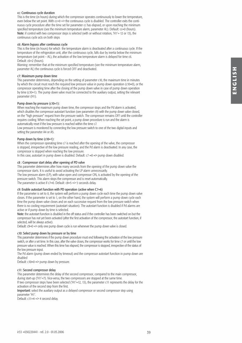
39
EN
GL
ISH
ir33 +030220441 - rel. 2.0 - 01.05.2006
cc: Continuous cycle durationThis is the time (in hours) during which the compressor operates continuously to lower the temperature, even below the set point. With cc=0 => the continuous cycle is disabled. The controller exits the conti-nuous cycle procedure after the time set for parameter cc has elapsed, or upon reaching the minimum specifi ed temperature (see the minimum temperature alarm, parameter AL). Default: cc=0 (hours).Note: if control with two compressor steps is selected (with or without rotation, ‘H1’= 12 or 13), the continuous cycle acts on both steps
c6: Alarm bypass after continuous cycleThis is the time (in hours) for which the temperature alarm is deactivated after a continuous cycle. If the temperature of the refrigeration unit, after the continuous cycle, falls due by inertia below the minimum temperature (set point – AL), the activation of the low temperature alarm is delayed for time c6. Default: c6=2 (hours).Warning: remember that at the minimum specifi ed temperature (see the minimum temperature alarm, parameter AL) the continuous cycle is forced OFF and deactivated.
c7: Maximum pump down timeThis parameter determines, depending on the setting of parameter c10, the maximum time in minutes by which the circuit must reach the required low pressure value in pump down operation (c10=0), or the compressor operating time after the closing of the pump down valve in case of pump down operation by time (c10=1). The pump down valve must be connected to the auxiliary output, setting the relevant parameter (H1).
Pump down by pressure (c10=1):When reaching the maximum pump down time, the compressor stops and the Pd alarm is activated, which disables the compressor autostart function (see parameter c9) with the pump down valve closed, on the “high pressure” request from the pressure switch. The compressor remains OFF until the controller requires cooling. When reaching the set point, a pump down procedure is run and the alarm is automatically reset if the low pressure is reached within the time c7.Low pressure is monitored by connecting the low pressure switch to one of the two digital inputs and setting the parameter A4 or A5.
Pump down by time (c10=1):When the compressor operating time c7 is reached after the opening of the valve, the compressor is stopped, irrespective of the low pressure reading, and the Pd alarm is deactivated. In any case, the compressor is stopped when reaching the low pressure.In this case, autostart in pump down is disabled. Default: c7 =0 => pump down disabled.
c8 : Compressor start delay after opening of PD valveThis parameter determines after how many seconds from the opening of the pump down valve the compressor starts. It is useful to avoid activating the LP alarm unnecessarily.The low pressure alarm (LP), with valve open and compressor ON, is activated by the opening of the pressure switch. This alarm stops the compressor and is reset automatically.The parameter is active if c7=0. Default: c8=5 => 5 seconds delay.
c9: Enable autostart function with PD operation (active when C7=6)If the parameter is set to 0, the system will perform a pump down cycle each time the pump down valve closes. If the parameter is set to 1, on the other hand, the system will perform a pump down cycle each time the pump down valve closes and on each successive request from the low pressure switch when there is no cooling requirement (autostart situation). The autostart function is disabled if Pd alarms are active or if pump down by time is selected.Note: the autostart function is disabled in the off status and if the controller has been switched on but the compressor has not yet been activated (after the fi rst activation of the compressor, the autostart function, if selected, will be always active).Default: c9=0 => only one pump down cycle is run whenever the pump down valve is closed.
c10: Select pump down by pressure or by timeThis parameter determines if the pump down procedure must end following the activation of the low pressure switch, or after a set time. In this case, after the valve closes, the compressor works for time c7 or until the low pressure value is reached. When this time has elapsed, the compressor is stopped, irrespective of the status of the low pressure input.The Pd alarm (pump down ended by timeout) and the compressor autostart function in pump down are disabledDefault: c10=0 => pump down by pressure.
c11: Second compressor delayThis parameter determines the delay of the second compressor, compared to the main compressor, during start-up (‘H1’=7). Vice-versa, the two compressors are stopped at the same time.If two compressor steps have been selected (‘H1’=12, 13), the parameter c11 represents the delay for the activation of the second step from the fi rst.Important: select the auxiliary output as a delayed compressor or second compressor step using parameter ‘H1’.Default: c11=4 => 4 second delay.
40
EN
GL
ISH
ir33 +030220441 - rel. 2.0 - 01.05.2006
7.4 Defrost management parameters
Code Parameter MSYF ** UOM Type Min Max Def.d0 Type of defrost -SYF fl ag C 0 4 0dI Interval between defrosts -SYF hours F 0 250 8dt1 End defrost temperature, evaporator -SYF °C/°F F -50 200 4.0dt2 End defrost temperature, aux evap. -SYF °C/°F F -50 200 4.0dP1 Maximum defrost duration, evaporator -SYF min F 1 250 30dP2 Maximum defrost duration, aux evap. -SYF min F 1 250 30d3 Defrost start delay -SYF Min C 0 250 0d4 Enable defrost on start-up -SYF fl ag C 0 1 0d5 Defrost delay on start-up -SYF min C 0 250 0d6 Display on hold during defrost -SYF - C 0 2 1dd Dripping time after defrost -SYF min F 0 15 2d8 Alarm bypass after defrost -SYF hours F 0 15 1d8d Alarm bypass after door open -SYF hours/
minC 0 250 0
d9 Defrost priority over compressor protectors -SYF fl ag C 0 1 0d/1 Display of defrost probe 1 MSYF °C/°F F - - -d/2 Display of defrost probe 2 MSYF °C/°F F - - -dC Time base for defrost -SYF fl ag C 0 1 0d10 Compressor running time -SYF hours C 0 250 0d11 Running time temperature threshold -SYF °C/°F C -20 20 1.0d12 Advanced defrost -SYF - C 0 3 0dn Nominal defrost duration -SYF - C 1 100 65dH Proportional factor, variation in dI -SYF - C 0 100 50
Tab. 7.eImportant warning: afor the set times to become immediately operational, the instrument needs to be turned off and on again. If this operation is not carried out, timing resumes operation the next time it is used.
d0: Type of defrostFor the instruments fi tted with defrost relays:• d0=0 electric heater defrost by temperature;• d0=1 hot gas defrost by temperature;• d0=2 electric heater defrost by time, Ed1 and Ed2 not displayed;• d0=3 hot gas defrost by time, Ed1 and Ed2 not displayed.Defrosts can be performed for all models: • by temperature, using the defrost probe fi tted on the evaporator. In any case, the defrost will be
stopped after a maximum set safety time (dP1 and dP2). The warnings Ed1 and Ed2, “end defrost due to maximum duration” (parameter ‘A8’) can be disabled;
• by time: without the defrost probe;• by time with temperature control: based on the evaporator temperature, the function is similar to the
mode where d0=0. Once the temperatures dt1 and dt2 (end defrost) have been reached, the defrost does not end completely, and the controller reactivates the defrost output if the temperature falls below dt1 and dt2. This occurs for the entire duration of the defrost set using the parameter dP.
Note:• model S does not have a defrost relay, and consequently the defrost can only be performed by stopping the compressor and selecting end of defrost by time or temperature. If the alarms Ed1 and
Ed2 are not disabled, when activated, they can be cancelled by pressing * and AUX together for more than 5 seconds, or automatically at the start of the next defrost operation.
• if control with two compressor steps is selected (with or without rotation, H1= 12 or 13) the defrost is performed acting on both steps.
Default: d0=0 => electric heater defrost by temperature.
dI: Interval between defrostsThe defrosts are performed cyclically at an interval equal to the value of dI in hours (or minutes, see parameter dC), counted from the end of the previous period. The duration of the defrost therefore does not therefore affect the interval between defrosts. The interval dI is also maintained when the unit is OFF. If the interval dI expires when the controller is OFF, when it is started again a defrost is performed.If dI =0 => the defrost is never performed except when forced from the keypad (manual defrost), from the supervisor or from the digital input (see parameter A4), or from the Real Time Clock.Important: PTo ensure regular defrosts, the interval between defrosts must be greater than the maxi-mum defrost duration, plus the dripping time and post-dripping time. Note: during the defrost, the temperature alarms are disabled.Default: dI =8 hour.
41
EN
GL
ISH
ir33 +030220441 - rel. 2.0 - 01.05.2006
dt1: evaporator end defrost temperature set pointThis parameter is used to set the end defrost temperature, measured on the evaporator. In any case, the maximum defrost duration is equal to the value, in minutes, set for parameter dP1.• if when a defrost is requested, the temperature measured by the defrost probe on the evaporator is
greater than the value set for the end defrost, the cycle is not performed (including the dripping and post-dripping phases). The same is true for the defrost on start-up, from digital contact, from RTC and from the keypad;
• if the defrost probe on the evaporator is faulty or disabled, the controller performs a timed defrost, with a duration equal to the value set for parameter dP1;
• if the end defrost set point is not reached within the time set for parameter dP1, the defrost is stopped. If enabled (parameter A8), the error Ed1 is displayed, which persists until the start of the next defrost cycle.
In the defrost by temperature, the parameter establishes the threshold for activating or deactivating the corresponding defrost relay.Default: dt1=4°C.
dt2: end defrost temperature set point, auxiliary evaporatordt2 acts in the same way as parameter dt1 described above, but referring to the auxiliary evaporator. Note for dt1 and dt2: in the defrost by temperature, the parameter establishes the threshold for activating or deactivating the corresponding defrost relay.Default: dt2 =4°C.
dP1: Maximum evaporator defrost durationDetermines the maximum defrost duration on the evaporator in minutes (or seconds, see parameter dC) if defrost by temperature is selected. If timed defrost has been selected, this is the actual duration of the defrost. Default: dP1=30 minutes.
dP2: Maximum defrost duration, auxiliary evaporatorAs for parameter dP1 described above, but refers to the auxiliary evaporator.Default: dP2=30 minutes.
d3: Defrost start delayThis parameter determines the time that must elapse, when the defrost is activated, between the stopping of the compressor (electric heater defrost) or the starting of the compressor (hot gas defrost), and the activation of the defrost relays on the main and auxiliary evaporators.The delay d3 is useful, in the hot gas defrost, to ensure a suffi cient quantity of hot gas for the defrost before the activation of the cycle reversing valve, in very special applications (see paragraph “Description of software functions”). Default: d3=0 minutes.
d4: Defrost when the instrument is switched onActivates a defrost when the instrument is switched on. Warning: this request has priority over the activation of the compressor and the continuous cycle.The possible values are:d4=0, no defrost is performed when the instrument is switched on;d4=1, a defrost is performed when the instrument is switched on.Starting a defrost when the instrument is switched on may be useful in special situations.
Example: frequent power drops occur in the system, which cause the internal clock to be reset. This clock calculates the interval between two defrosting operations, restarting from zero. If the frequency of the power failure were, in an extreme case, greater than the defrost frequency (e.g. a power failure every 8 hours, against a defrost every 10 hours) the controller would never perform a defrost. In a situation of this type, it is preferable to enable defrost on start-up, above all if the defrost is controlled by temperatu-re (probe on the evaporator), therefore avoiding unnecessary defrosts or at least reducing the running times. In the case of systems with a large number of units, if selecting defrosts at start-up, after a power failure all the units will start defrosting, thus causing a voltage overload. To overcome this, the parameter d5 can be used. It adds a delay before the defrost, and this delay must obviously be different for each unit.Default: d4=0 the instrument does not perform a defrost on start-up.Available on all models except for IR33M.
d5: Defrost delay when the instrument is switched on or from multifunction inputThe time that must elapse between start-up of the controller and the start of the defrost.• if the digital input is used to enable the defrost (see parameter A4=3) or to start a defrost from
external contact (see parameter A4=4), the parameter d5 refers to the delay between enabling of the defrost or request to enable, and the effective start.
• the defrost digital input (see parameter A4) can be usefully employed to perform defrosts in real time, connecting a timer to the input. The defrost will be activated when the timer contact closes.
• If several units are connected to the same timer, parameter d5 should be used to delay the various defrosts, thus avoiding power overloads.
In addition, to avoid unwanted defrosts started by the clock inside the instrument, set parameter dI=0 (manual defrosts only, started from the keypad, by the RTC, by the calculation of the compressor running time or by the multifunction contact).
Important warning: when connecting a series of units to the same timer, the best solution is to insulate all the contacts galvanically, fi tting intermediate relays for each contact.Default: d5=0 => no delayed defrost when switching the instrument on or following the activation of the multifunction input.
42
EN
GL
ISH
ir33 +030220441 - rel. 2.0 - 01.05.2006
d6: Display during defrostSpecifi ed values:• d6=0 => during the defrost the instrument displays the text dEF alternating with the value read by the
probe selected using parameter /tI. This is to signal that any high temperature values are due to the defrost procedure in progress.
• d6=1 => during the defrost the last temperature shown before the start of the cycle remains on the display. The display returns to normal when the control temperature reaches the set point, the tempe-rature to be displayed is less than the value locked on the display or, in any case, after the time set for the “alarm bypass after defrosting” (d8).
• d6=2 => during the defrost the instrument displays the text dEF steady on the display.Note: in OFF and REVERSE modes, the display is unlocked after the defrost.Default: d6=1 => during the defrost the last temperature read before the start of the cycle remains on the display, both on the built-in terminal and on the remote terminal.
dd: Dripping timeThis parameter is used to stop (in minutes) the compressor and the evaporator fans after a defrost to facilitate evaporator dripping.If dd=0 => there is no dripping time, therefore, at the end of the defrost the control functions start immediately. Default: dd=2 minutes.Note: if control with two compressor steps is selected (with or without rotation, H1= 12 or 13) the dripping acts on both steps.
d8: Alarm bypass time after defrost and/or door openIndicates the time (in hours) that the high temperature alarm signal is ignored from after the end of a defrost cycle or from when the door to the cold room is opened, if the Multifunction input is connected to the “door switch” (see parameters A4 and A5).Important: parameter ‘d8’ can be expressed in hours ‘dC1’=0 (default) or minutes ‘dC1’=1.Parameter dC1 is masked and consequently not visible.Default: d8 =1 hour bypass.
d8d: Open door alarm delay.This indicates the delay to signal that the door is open, if the multifunction input is connected to the “door switch” (see parameter ‘A4’, ‘A5’ or ‘A9’). If ‘d8d’= 0, parameter ‘d8d’ is disabled and the open door alarm delay returns to ‘d8’. Default: ‘d8d’=0 disabled.
d9: Defrost priority over compressor protective devicesIgnores the compressor protection times at the start of the defrost. Compressor protection times:• c1: minimum time between 2 successive starts;• c2: minimum OFF time;• c3: minimum operating time.d9 = 0 the protection times are respectedd9 = 1 the protection times are not respected. Therefore, defrost has higher priority and the compressor times are ignored.In the hot gas defrost, this is useful to avoid delaying the start of the defrost if the compressor has just stopped and there is a minimum time between two starts of the compressor. Remember, however, that in this event the maximum number of compressor starts per hour may not necessarily be respected.Warning: if the defrost requires the activation of the compressor (hot gas defrost) and parameter d9=1, the compressor may risk being damaged due to an excessive number of close starts.Default: d9=0 => the defrost respects the compressor times (however by default these are set to zero).
d/1: Defrost probe 1 readingThis parameter is used to display the value measured by defrost probe 1 (on the instruments where this is fi tted), by pressing SET.If defrost probe 1 is disabled, three horizontal dashes ‘_ _ _’ will be displayed.
d/2: Defrost probe 2 readingAs for parameter d/1 described above, but refers to defrost probe 2.
dC: Time baseUsed to modify the measurement unit used to count the times set for parameters dI (defrost interval), dP1 and dP2 (defrost duration).dC=0 =>dI expressed in hours, dP1 and dP2 in minutes.dC=1 =>dI expressed in minutes, dP1 and dP2 in seconds.The parameter dC=1 can be used to test defrost operation at shorter times. In addition, it is useful for using the instrument to manage air driers. The defrost cycle then becomes the condensate discharge cycle, which must be performed at close intervals (minutes) and for short durations (seconds).Default: dC=0 =>dI expressed in hours, dP1 and dP2 in minutes.
d10: Compressor running timeThis parameter indicates the compressor operating time in hours, with the temperature below the threshold indicated by the parameter d11, after which a defrost request is generated. Setting d10=0 disables the function.Note: if control with two compressor steps is selected (with or without rotation, H1= 12 or 13) the compressor running time is only calculated on the fi rst step.Default: d10=0 => Function disabled.
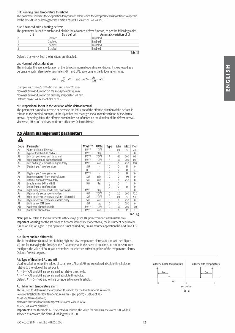
43
set point
allarme bassa temperatura allarme alta temperatura
A0 A0
AL
Fig. 7.i
EN
GL
ISH
ir33 +030220441 - rel. 2.0 - 01.05.2006
d11: Running time temperature thresholdThis parameter indicates the evaporation temperature below which the compressor must continue to operate for the time d10 in order to generate a defrost request. Default: d11 =1 => 1°C.
d12: Advanced auto-adapting defrostsThis parameter is used to enable and disable the advanced defrost function, as per the following table:
d12 Skip defrost Automatic variation of dI0 Disabled Disabled1 Disabled Enabled2 Enabled Disabled3 Enabled Enabled
Tab. 7.f Default: d12 =0 => Both the functions are disabled.
dn: Nominal defrost durationThis indicates the average duration of the defrost in normal operating conditions. It is expressed as a percentage, with reference to parameters dP1 and dP2, according to the following formulae:
dn1 dP1100dn
and dn2 dP2100dn
Example: with dn=65, dP1=90 min. and dP2=120 min.Nominal defrost duration on main evaporator: 59 min.Nominal defrost duration on auxiliary evaporator: 78 min.Default: dn=65 => 65% of dP1 or dP2
dH: Proportional factor in the variation of the defrost intervalThis parameter is used to increase or decrease the infl uence of the effective duration of the defrost, in relation to the nominal duration, in the algorithm that manages the automatic variation of the defrost interval. By setting dH=0, the effective duration has no infl uence on the duration of the defrost interval. Vice versa, dH = 100 achieves maximum effi ciency. Default: dH=50
7.5 Alarm management parameters
Code Parameter MSYF ** UOM Type Min Max Def.A0 Alarm and fan differential MSYF °C/°F C 0.1 20 2.0A1 Type of threshold AL and AH MSYF fl ag C 0 1 0AL Low temperature alarm threshold MSYF °C/°F F -50 200 0.0AH High temperature alarm threshold MSYF °C/°F F -50 200 0.0Ad Low and high temperature signal delay MSYF min F 0 250 120A4 Digital input 1 confi guration -SYF - C 0 14 0
M--- - C 0 14 3A5 Digital input 2 confi guration MSYF - C 0 14 0A6 Stop compressor from external alarm -SYF min C 0 100 0A7 External alarm detection delay -SYF min C 0 250 0A8 Enable alarms Ed1 and Ed2 -SYF fl ag C 0 1 0A9 Digital input 3 confi guration - C 0 14 0Ado Light management mode with door switch MSYF fl ag C 0 1 0Ac High condenser temperature alarm -SYF °C/°F C 0.0 200 70.0AE High condenser temperature alarm differential -SYF °C/°F C 0.1 20 5.0Acd High condenser temperature alarm delay -SYF min C 0 250 0AF Light sensor OFF time -SYF sec C 0 250 0ALF Antifreeze alarm threshold MSYF °C/°F C -50 200 -5.0AdF Antifreeze alarm delay MSYF min C 0 15 1
Tab. 7.g Note: par. A9 refers to the instruments with 5 relays (ir33DIN, powercompact and MasterCella).Important warning: for the set times to become immediately operational, the instrument needs to be turned off and on again. If this operation is not carried out, timing resumes operation the next time it is used.
A0: Alarm and fan differentialThis is the differential used for disabling high and low temperature alarms (AL and AH - see Figure 7.i) and for managing the fans (see the F parameters). In the event of an alarm, as can be seen from the fi gure, the value of A0 in part determines the effective activation points of the temperature alarms. Default: A0=2.0 degrees.
A1: Type of threshold AL and AHUsed to select whether the values of parameters AL and AH are considered absolute thresholds or relative to the value of the set point.A1 = 0 => AL and AH are considered as relative thresholds.A1 = 1 => AL and AH are considered absolute thresholds.Default: A1 = 0 => AL and AH are considered relative thresholds.
AL : Minimum temperature alarmThis is used to determine the activation threshold for the low temperature alarm.Relative threshold for low temperature alarm = (set point) - (value of AL)AL=0 => Alarm disabled;Absolute threshold for low temperature alarm = value of AL.AL=-50 => Alarm disabled.Important: If the threshold AL is selected as relative, the value for disabling the alarm is 0, while if selected as absolute, the alarm disabling value is -50.
44
EN
GL
ISH
ir33 +030220441 - rel. 2.0 - 01.05.2006
Warnings for the relative threshold:The value of AL does not indicate the actual alarm temperature, but the maximum permissible deviation from the set point; changing the set point automatically changes the low temperature alarm, while the maximum deviation allowed (=AL ) remains fi xed.Note: the low temperature alarm features automatic reset (this means that if the temperature returns above the minimum value set, the alarm signal is cancelled automatically).
Warnings for using the continuous cycleThe low temperature alarm is also used in the continuous cycle (see the description of parameter cc’. In fact, if the temperature falls to the alarm level, the continuous cycle is stopped automatically, even if the selected time has not yet elapsed. This deactivation, however, does not involve an alarm signal. Default: AL =0 => low temperature alarm disabled.Note: for the control probe alarm, the low temperature alarm is reset and monitoring reinitialised.
AH: High temperature alarmThis is used to determine the activation threshold for the high temperature alarm.Relative threshold for high temperature alarm = (set point) + (value of AH)AH=0 => Alarm disabled;Absolute threshold for high temperature alarm = value of AH.AH=200 => Alarm disabled.Important: if the threshold AH is selected as relative, the value for disabling the alarm is 0, while if selected as absolute, the alarm disabling value is 200.Warnings for the relative threshold:• the value of AH does not indicate the alarm temperature, but the maximum permissible deviation from
the set point; consequently, changing the set point automatically changes the high temperature alarm, while the maximum deviation allowed (=AH) remains fi xed.
Warnings:• the high temperature alarm has automatic reset: this means that if the temperature returns above/be-
low the minimum value envisaged, the alarm signal is cancelled automatically • in the event of a control probe alarm, the high temperature alarm is reset and monitoring reinitialised.Default: AH=0 => high temperature alarm disabled.
Ad: Temperature alarm delayIndicates after how many minutes the temperature alarm is signalled when the temperature threshold is exceeded.Warnings:• Setting a delay for signalling the temperature alarm may help eliminate false alarms due to interference
on the probe signal or brief situations (for example, the door to the cold room opened for a short period);
• no temperature alarms are generated during the defrost and continuous cycle procedures;• the temperature alarm is delayed by the time d8 after the defrost and by the time c6 after the continuous
cycle. At the end of these two times, the temperature alarm, if detected, is signalled without waiting for the time set for Ad. If d8 and c6 are set to zero, the temperature alarm is signalled after the time Ad;
• as already indicated by the default value for parameters AL and AH, the instruments are programmed in the factory with the relevant thresholds, and the high and low temperature alarms are disabled. The alarms, when enabled, activate the buzzer, if enabled, and show a code on the display: HI for the high temperature and LO for the low temperature alarm.
The following conditions generate the temperature alarms: • high temperature alarm: the temperature measured by the virtual control probe is above the threshold
set for parameter AH;• low temperature alarm: the temperature measured by the virtual control probe is below the threshold
set for parameter AL.Default: Ad=120 => 120 minute delay for the temperature alarms.
A4: Multifunction digital input confi guration In the ir33 series, this parameter and the model of controller used defi ne the meaning of the multifunction digital input. The possibilities are described below:A4=0 Input not active: the multifunction digital input is not used and is the factory-specifi ed confi guration for all versions.A4=1 Immediate external alarm: the digital input can be connected to an external alarm that requires immediate activation (for example, high pressure alarm or compressor thermal overload). Specifi cally, the alarm is detected when the contact opens (normal operation with contact closed). The activation of the alarm:• shows the message on the display (IA);• activates the buzzer, if enabled;• activates the alarm relay, if selected;• involves the following actions on the actuators: - compressor: operates depending on the values assigned to parameter A6 (stop compressor from external alarm). - fans: continue to operate according to the fan parameters (F).When stopping the compressor, the minimum ON time (c3) is ignored. When the alarm stops, the defrost and the continuous cycle can be performed again, and the compressor returns to normal operation.
Important warning: remember that in order to ensure the safety of the unit in the event of serious alarms, all the electromechanical safety devices required to guarantee correct operation must be fi tted on the unit.
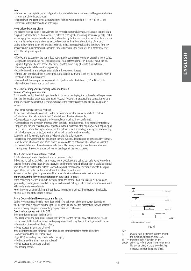
45
d5
d
dP
t
d5
sbrinamento
sbrinamento
sbrinamento
tempo
unità 1
unità 2
unità 3
richiesta di sbrinamento
Fig. 7.l
EN
GL
ISH
ir33 +030220441 - rel. 2.0 - 01.05.2006
Note: • if more than one digital input is confi gured as the immediate alarm, the alarm will be generated when
at least one of the inputs is open.• if control with two compressor steps is selected (with or without rotation, H1, H5 = 12 or 13) the
immediate external alarm acts on both steps.
A4=2 Delayed external alarmThe delayed external alarm is equivalent to the immediate external alarm (A4=1), except that this alarm is signalled after the time A7 from when it is detected (‘dA’ signal). This confi guration is especially useful for managing the low pressure alarm. In fact, when starting for the fi rst time, the unit often detects a low pressure alarm due to the environmental conditions rather than the malfunctioning of the unit.Setting a delay for the alarm will avoid false signals. In fact, by suitably calculating the delay, if the low pressure is due to environmental conditions (low temperature), the alarm will be automatically reset before the delay has elapsed.Note: • if ‘A7’=0, the activation of the alarm does not cause the compressor to operate according to the values
assigned to the parameter ‘A6’ (stop compressor from external alarm); on the other hand, the ‘dA’ signal is displayed, the icon fl ashes, the buzzer and the alarm relay (if selected) are activated;
the delayed external alarm is thus signal-only.• both the immediate and delayed external alarm have automatic reset;• if more than one digital input is confi gured as the delayed alarm, the alarm will be generated when at
least one of the inputs is open;• if control with two compressor steps is selected (with or without rotation, H1, H5 = 12 or 13) the
delayed external alarm acts on both steps.
A4 =3 The meaning varies according to the model usedVersion ir33M = probe selectionThis is used to exploit the digital input in order to show, on the display, the probe selected by parameter /tI or the fi rst enabled probe (see parameters /A2, /A3, /A4, /A5). In practice, if the contact is open, the probe selected by parameter /tl is shown, whereas, if the contact is closed, the fi rst enabled probe is shown.
For all other models = Defrost enablingAn external contact can be connected to the multifunction input to enable or inhibit the defrost.• Contact open: the defrost is inhibited. Contact closed: the defrost is enabled.• Contact closed without request from the controller: the defrost is not performed.• Contact closed and defrost in progress: when the digital input is opened, the defrost is immediately
stopped and the unit restarts normal operation (without performing the dripping or post-dripping pha-ses). The LED starts fl ashing to indicate that the defrost request is pending, awaiting the next enabling signal (closing of the contact), when the defrost will be performed completely..
Suggestion: this function is useful in the following situations, for example:- multiplexed showcases with hot gas defrost. In these systems, defrosts must be performed by “islands”,
and therefore, at any one time, some islands are enabled to be defrosted, while others are disabled;- to prevent defrosts on the units accessible by the public during opening times. Any defrost request
arriving when the contact is open will remain pending until the contact closes.
A4 = 4 Start defrost from external contactThis function used to start the defrost from an external contact.If dI=0 and no defrost enabling signal related to the clock is set, the defrost can only be performed on start-up, from the digital input, by the supervisor and from the keypad. This function is useful to run real time defrosts. To perform the defrosts, connect a cyclical, mechanical or electronic timer to the digital input: When the contact on the timer closes, the defrost request is sent. As seen in the description of parameter d5, a series of units can be connected to the same timer.Important warning for versions operating on 12Vac and 12-24VacWhen connecting a series of units to the same timer, the best solution is to insulate all the contacts galvanically, inserting an intermediate relay for each contact. Setting a different value for d5 on each unit will avoid simultaneous defrosts.Note: if more than one digital input is confi gured to enable the defrost, the defrost will be disabled when at least one of the inputs is closed.
A4 = 5 Door switch with compressor and fan stop Setting A4=5 manages the cold room door switch. The behaviour of the door switch depends on whether the door is opened with the light OFF or light ON. The need to differentiate the two operating modes is mainly designed for controlling display cases and cold rooms.Case 1 - door opened with light OFF:If the door is opened with the light OFF:• the compressor and evaporator fans are switched off (to stop the fans only, set parameter A4=9); • in the models fi tted with an auxiliary relay programmed as the light output, the light is switched on;• the reading displayed and the icon fl ash;• the temperature alarms are disabled.If the door remains open for longer than time d8, the controller restarts normal operation:• compressor and fan ON, if requested;• light ON (the auxiliary relay is selected as the light);• the buzzer and the alarm relay are activated;• the temperature alarms are enabled;• the reading fl ashes.
Key:t= impulse from the timer to start the defrost: the minimum duration must be 0.5 s.dP (1)= maximum defrost duration on unit 1.dP(2)= defrost delay from external contact for unit 2, higher than dP(1) to prevent overlapping defrosts. Same for d5(3) and dP(3).
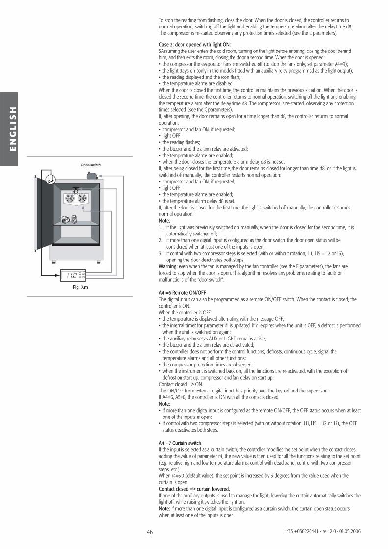
46
Fig. 7.m
EN
GL
ISH
ir33 +030220441 - rel. 2.0 - 01.05.2006
To stop the reading from fl ashing, close the door. When the door is closed, the controller returns to normal operation, switching off the light and enabling the temperature alarm after the delay time d8. The compressor is re-started observing any protection times selected (see the C parameters).
Case 2: door opened with light ON:SAssuming the user enters the cold room, turning on the light before entering, closing the door behind him, and then exits the room, closing the door a second time. When the door is opened:• the compressor the evaporator fans are switched off (to stop the fans only, set parameter A4=9);• the light stays on (only in the models fi tted with an auxiliary relay programmed as the light output);• the reading displayed and the icon fl ash;• the temperature alarms are disabledWhen the door is closed the fi rst time, the controller maintains the previous situation. When the door is closed the second time, the controller returns to normal operation, switching off the light and enabling the temperature alarm after the delay time d8. The compressor is re-started, observing any protection times selected (see the C parameters).If, after opening, the door remains open for a time longer than d8, the controller returns to normal operation:• compressor and fan ON, if requested;• light OFF;• the reading fl ashes;• the buzzer and the alarm relay are activated;• the temperature alarms are enabled;• when the door closes the temperature alarm delay d8 is not set.If, after being closed for the fi rst time, the door remains closed for longer than time d8, or if the light is switched off manually, the controller restarts normal operation:• compressor and fan ON, if requested;• light OFF;• the temperature alarms are enabled;• the temperature alarm delay d8 is set.If, after the door is closed for the fi rst time, the light is switched off manually, the controller resumes normal operation.Note: 1. if the light was previously switched on manually, when the door is closed for the second time, it is
automatically switched off;2. if more than one digital input is confi gured as the door switch, the door open status will be considered when at least one of the inputs is open;3. if control with two compressor steps is selected (with or without rotation, H1, H5 = 12 or 13), opening the door deactivates both steps.Warning: even when the fan is managed by the fan controller (see the F parameters), the fans are forced to stop when the door is open. This algorithm resolves any problems relating to faults or malfunctions of the “door switch”.
A4 =6 Remote ON/OFFThe digital input can also be programmed as a remote ON/OFF switch. When the contact is closed, the controller is ON. When the controller is OFF:• the temperature is displayed alternating with the message OFF;• the internal timer for parameter dI is updated. If dI expires when the unit is OFF, a defrost is performed
when the unit is switched on again;• the auxiliary relay set as AUX or LIGHT remains active;• the buzzer and the alarm relay are de-activated;• the controller does not perform the control functions, defrosts, continuous cycle, signal the temperature alarms and all other functions;• the compressor protection times are observed;• when the instrument is switched back on, all the functions are re-activated, with the exception of
defrost on start-up, compressor and fan delay on start-up.Contact closed => ON.The ON/OFF from external digital input has priority over the keypad and the supervisor.If A4=6, A5=6, the controller is ON with all the contacts closedNote:• if more than one digital input is confi gured as the remote ON/OFF, the OFF status occurs when at least
one of the inputs is open;• if control with two compressor steps is selected (with or without rotation, H1, H5 = 12 or 13), the OFF
status deactivates both steps.
A4 =7 Curtain switchIf the input is selected as a curtain switch, the controller modifi es the set point when the contact closes, adding the value of parameter r4; the new value is then used for all the functions relating to the set point (e.g. relative high and low temperature alarms, control with dead band, control with two compressor steps, etc.).When r4=3.0 (default value), the set point is increased by 3 degrees from the value used when the curtain is open.Contact closed => curtain lowered.If one of the auxiliary outputs is used to manage the light, lowering the curtain automatically switches the light off, while raising it switches the light on.Note: if more than one digital input is confi gured as a curtain switch, the curtain open status occurs when at least one of the inputs is open.
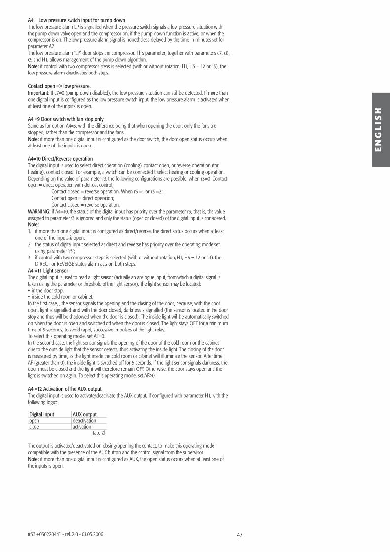
47
EN
GL
ISH
ir33 +030220441 - rel. 2.0 - 01.05.2006
A4 = Low pressure switch input for pump downThe low pressure alarm LP is signalled when the pressure switch signals a low pressure situation with the pump down valve open and the compressor on, if the pump down function is active, or when the compressor is on. The low pressure alarm signal is nonetheless delayed by the time in minutes set for parameter A7.The low pressure alarm ‘LP’ door stops the compressor. This parameter, together with parameters c7, c8, c9 and H1, allows management of the pump down algorithm.Note: if control with two compressor steps is selected (with or without rotation, H1, H5 = 12 or 13), the low pressure alarm deactivates both steps.
Contact open => low pressure.Important: If c7=0 (pump down disabled), the low pressure situation can still be detected. If more than one digital input is confi gured as the low pressure switch input, the low pressure alarm is activated when at least one of the inputs is open.
A4 =9 Door switch with fan stop onlySame as for option A4=5, with the difference being that when opening the door, only the fans are stopped, rather than the compressor and the fans.Note: if more than one digital input is confi gured as the door switch, the door open status occurs when at least one of the inputs is open.
A4=10 Direct/Reverse operationThe digital input is used to select direct operation (cooling), contact open, or reverse operation (for heating), contact closed. For example, a switch can be connected t select heating or cooling operation.Depending on the value of parameter r3, the following confi gurations are possible: when r3=0 Contact open = direct operation with defrost control; Contact closed = reverse operation. When r3 =1 or r3 =2; Contact open = direct operation; Contact closed = reverse operation.WARNING: if A4=10, the status of the digital input has priority over the parameter r3, that is, the value assigned to parameter r3 is ignored and only the status (open or closed) of the digital input is considered.Note:1. if more than one digital input is confi gured as direct/reverse, the direct status occurs when at least
one of the inputs is open;2. the status of digital input selected as direct and reverse has priority over the operating mode set
using parameter ‘r3’;3. if control with two compressor steps is selected (with or without rotation, H1, H5 = 12 or 13), the
DIRECT or REVERSE status alarm acts on both steps.A4 =11 Light sensorThe digital input is used to read a light sensor (actually an analogue input, from which a digital signal is taken using the parameter or threshold of the light sensor). The light sensor may be located:• in the door stop,• inside the cold room or cabinet.In the fi rst case, , the sensor signals the opening and the closing of the door, because, with the door open, light is signalled, and with the door closed, darkness is signalled (the sensor is located in the door stop and thus will be shadowed when the door is closed). The inside light will be automatically switched on when the door is open and switched off when the door is closed. The light stays OFF for a minimum time of 5 seconds, to avoid rapid, successive impulses of the light relay.To select this operating mode, set AF=0.In the second case, the light sensor signals the opening of the door of the cold room or the cabinet due to the outside light that the sensor detects, thus activating the inside light. The closing of the door is measured by time, as the light inside the cold room or cabinet will illuminate the sensor. After time AF (greater than 0), the inside light is switched off for 5 seconds. If the light sensor signals darkness, the door must be closed and the light will therefore remain OFF. Otherwise, the door stays open and the light is switched on again. To select this operating mode, set AF>0.
A4 =12 Activation of the AUX outputThe digital input is used to activate/deactivate the AUX output, if confi gured with parameter H1, with the following logic:
Digital input AUX outputopen deactivationclose activation
Tab. 7.h The output is activated/deactivated on closing/opening the contact, to make this operating mode compatible with the presence of the AUX button and the control signal from the supervisor.Note: if more than one digital input is confi gured as AUX, the open status occurs when at least one of the inputs is open.
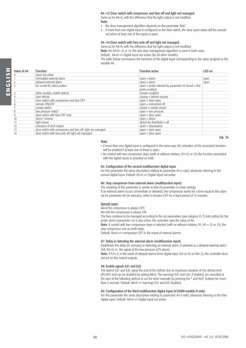
48
EN
GL
ISH
ir33 +030220441 - rel. 2.0 - 01.05.2006
A4 =13 Door switch with compressor and fans off and light not managed.Same as for A4=5, with the difference that the light output is not modifi ed.Note:1. the door management algorithm depends on the parameter ‘Ado’.2. if more than one digital input is confi gured as the door switch, the door open status will be conside-
red when at least one of the inputs is open.
A4 =14 Door switch with fans only off and light not managed.Same as for A4=9, with the difference that the light output is not modifi ed.Note: for A4/5= 13 or 14: the Ado door management algorithm is used in both cases.Default: A4=0 => Digital input not active (for all other models).The table below summarises the functions of the digital input corresponding to the value assigned to the variable A4.
Value of A4 Function Function active LED on0 input not active1 immediate external alarm open = alarm open2 delayed external alarm open = alarm open3 for model M, select probes open = probe selected by parameter /tI closed = fi rst
probe enabled3 other models, enable defrost closed= enabled4 start defrost closing = defrost request5 door switch with compressor and fans OFF open = door open6 remote ON/OFF open = instrument off7 curtain switch closed = curtain closed8 low pressure switch open = low pressure9 door switch with fans OFF only open = door open10 direct / reverse open = direct11 light sensor above the threshold = off12 activation of AUX output open = deactivation13 door switch with compressor and fans off, light not managed open = door open14 door switch with fans only off, light not managed open = door open
Tab. 7.hNote:• if more than one digital input is confi gured in the same way, the activation of the associated function
will be enabled if at least one of these is open.• for control with two compressor steps (with or without rotation, H1=12 or 13) the function associated
with the digital inputs is activated on both.
A5: Confi guration of the second multifunction digital input.For this parameter the same description relating to parameter A4 is valid, obviously referring to the second digital input. Default: A5=0 => Digital input not active.
A6: Stop compressor from external alarm (multifunction input)The meaning of this parameter is similar to that of parameter c4 (duty setting).If an external alarm occurs (immediate or delayed), the compressor works for a time equal to the value set for parameter A6 (in minutes), while it remains OFF for a fi xed period of 15 minutes.
Special cases:A6=0 the compressor is always OFF;A6=100 the compressor is always ON.The fans continue to be managed according to the set parameters (see category F). If duty setting for the probe alarm (parameter c4) is also active, the controller uses the value of A6.Note: if control with two compressor steps is selected (with or without rotation, H1, H5 = 12 or 13), the stop compressor acts on both steps.Default: A6=0 => compressor OFF in the event of external alarms.
A7: Delay in detecting the external alarm (multifunction input)Establishes the delay (in minutes) in detecting an external alarm, if selected as a delayed external alarm (A4, A5=2) or the signal of the low pressure (LP) alarm).Note: if A7= 0, in the event of delayed alarms from digital input (A4 or A5 or A9= 2), the controller does not act on the control outputs.
A8: Enable signals Ed1 and Ed2The alarms Ed1 and Ed2 signal the end of the defrost due to maximum duration of the defrost time dP1/dP2 and can be disabled by setting A8=0. The warnings Ed1 and Ed2, if enabled, are cancelled at the start of the following defrost or can be reset manually by pressing the * and AUX buttons for more than 5 seconds. Default: A8=0 => warnings Ed1 and Ed2 disabled.
A9: Confi guration of the third multifunction digital input (ir33DIN models H only)For this parameter the same description relating to parameter A4 is valid, obviously referring to the thirs digital input. Default: A9=0 => Digital input not active.
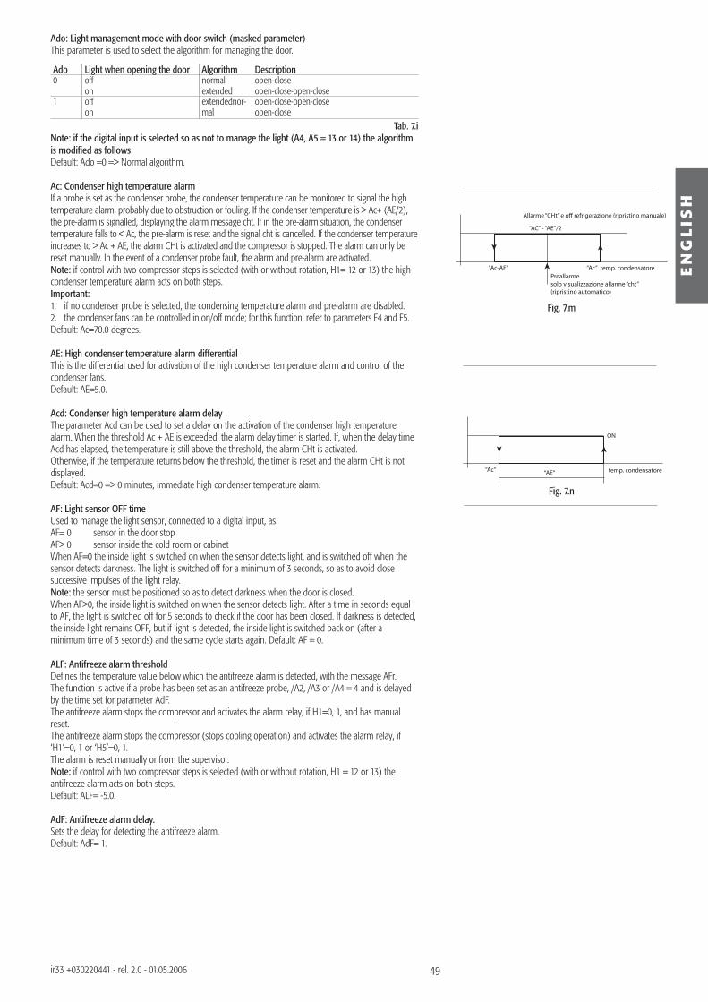
49
Allarme “CHt” e off refrigerazione (ripristino manuale)
temp. condensatorePreallarmesolo visualizzazione allarme “cht”(ripristino automatico)
“AC” - “AE”/2
“Ac”“Ac-AE”
ON
temp. condensatore“AE”“Ac”
Fig. 7.m
Fig. 7.n
EN
GL
ISH
ir33 +030220441 - rel. 2.0 - 01.05.2006
Ado: Light management mode with door switch (masked parameter)This parameter is used to select the algorithm for managing the door.
Ado Light when opening the door Algorithm Description0 off
onnormalextended
open-closeopen-close-open-close
1 offon
extendednor-mal
open-close-open-closeopen-close
Tab. 7.iNote: if the digital input is selected so as not to manage the light (A4, A5 = 13 or 14) the algorithm is modifi ed as follows:Default: Ado =0 => Normal algorithm.
Ac: Condenser high temperature alarmIf a probe is set as the condenser probe, the condenser temperature can be monitored to signal the high temperature alarm, probably due to obstruction or fouling. If the condenser temperature is > Ac+ (AE/2), the pre-alarm is signalled, displaying the alarm message cht. If in the pre-alarm situation, the condenser temperature falls to < Ac, the pre-alarm is reset and the signal cht is cancelled. If the condenser temperature increases to > Ac + AE, the alarm CHt is activated and the compressor is stopped. The alarm can only be reset manually. In the event of a condenser probe fault, the alarm and pre-alarm are activated.Note: if control with two compressor steps is selected (with or without rotation, H1= 12 or 13) the high condenser temperature alarm acts on both steps.Important:1. if no condenser probe is selected, the condensing temperature alarm and pre-alarm are disabled.2. the condenser fans can be controlled in on/off mode; for this function, refer to parameters F4 and F5.Default: Ac=70.0 degrees.
AE: High condenser temperature alarm differentialThis is the differential used for activation of the high condenser temperature alarm and control of the condenser fans.Default: AE=5.0. Acd: Condenser high temperature alarm delayThe parameter Acd can be used to set a delay on the activation of the condenser high temperature alarm. When the threshold Ac + AE is exceeded, the alarm delay timer is started. If, when the delay time Acd has elapsed, the temperature is still above the threshold, the alarm CHt is activated.Otherwise, if the temperature returns below the threshold, the timer is reset and the alarm CHt is not displayed.Default: Acd=0 => 0 minutes, immediate high condenser temperature alarm.
AF: Light sensor OFF timeUsed to manage the light sensor, connected to a digital input, as:AF= 0 sensor in the door stopAF> 0 sensor inside the cold room or cabinetWhen AF=0 the inside light is switched on when the sensor detects light, and is switched off when the sensor detects darkness. The light is switched off for a minimum of 3 seconds, so as to avoid close successive impulses of the light relay. Note: the sensor must be positioned so as to detect darkness when the door is closed.When AF>0, the inside light is switched on when the sensor detects light. After a time in seconds equal to AF, the light is switched off for 5 seconds to check if the door has been closed. If darkness is detected, the inside light remains OFF, but if light is detected, the inside light is switched back on (after a minimum time of 3 seconds) and the same cycle starts again. Default: AF = 0.
ALF: Antifreeze alarm thresholdDefi nes the temperature value below which the antifreeze alarm is detected, with the message AFr.The function is active if a probe has been set as an antifreeze probe, /A2, /A3 or /A4 = 4 and is delayed by the time set for parameter AdF.The antifreeze alarm stops the compressor and activates the alarm relay, if H1=0, 1, and has manual reset.The antifreeze alarm stops the compressor (stops cooling operation) and activates the alarm relay, if ‘H1’=0, 1 or ‘H5’=0, 1.The alarm is reset manually or from the supervisor.Note: if control with two compressor steps is selected (with or without rotation, H1 = 12 or 13) the antifreeze alarm acts on both steps.Default: ALF= -5.0.
AdF: Antifreeze alarm delay.Sets the delay for detecting the antifreeze alarm.Default: AdF= 1.
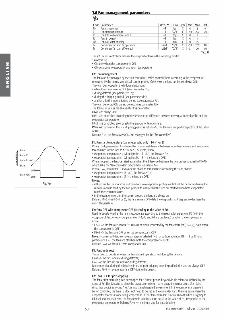
50
ON
OFF
Amb.
Amb. F1
Amb. F1 - A0
Evap.
Evap. Fan
tem
pera
tura
Fig. 7.o
EN
GL
ISH
ir33 +030220441 - rel. 2.0 - 01.05.2006
7.6 Fan management parameters
Code Parameter MSYF ** UOM Type Min Max Def.F0 Fan management ---F fl ag C 0 2 0F1 Fan start temperature ---F °C/°F F -50 200 5.0F2 Fan OFF with compressor OFF ---F fl ag C 0 1 1F3 Fans in defrost ---F fl ag C 0 1 1Fd Fan OFF after dripping ---F min F 0 15 1F4 Condenser fan stop temperature MSYF °C/°F C -50 200 40F5 Condenser fan start differential MSYF °C/°F C 0.1 20 5.0
Tab. 7.lThe ir33 series controllers manage the evaporator fans in the following modes:• always ON;• ON only when the compressor is ON;• ON according to evaporator and room temperature.
F0: Fan managementThe fans can be managed by the “fan controller”, which controls them according to the temperature measured by the defrost and virtual control probes. Otherwise, the fans can be left always ON.They can be stopped in the following situations:• when the compressor is OFF (see parameter F2);• during defrosts (see parameter F3);• during the dripping period (see parameter dd);• and for a further post-dripping period (see parameter Fd).They can be forced ON during defrosts (see parameter F3).The following values are allowed for this parameter:F0=0 fans always ON;F0=1 fans controlled according to the temperature difference between the virtual control probe and the evaporator temperature;F0=2 fans controlled according to the evaporator temperature.Warning: remember that if a dripping period is set (dd=0), the fans are stopped irrespective of the value of F0.Default: F0=0 => fans always ON, not managed by the “fan controller”.
F1: Fan start temperature (parameter valid only if F0 =1 or 2)When F0=1, parameter F1 indicates the minimum difference between room temperature and evaporator temperature for the fans to be started. Therefore, when:• evaporator temperature < (virtual probe – F1-A0), the fans are ON;• evaporator temperature > (virtual probe – F1), the fans are OFF.When stopped, the fans can start again when the difference between the two probes is equal to F1+A0, where A0 is the “fan controller” differential (see Figure 7.o).When F0=2, parameter F1 indicates the absolute temperature for starting the fans, that is:• evaporator temperature < (F1-A0), the fans are ON;• evaporator temperature > (F1), the fans are OFF.Notes:• if there are two evaporators and therefore two evaporator probes, control will be performed using the
maximum value read by the two probes, to ensure that the fans are started when both evaporators reach the set temperature.
• in the event of errors on the control probes, the fans are always on.Default: F1=5 =>(if F0=1 or 2), the fans remain ON while the evaporator is 5 degrees colder than the room temperature.
F2: Fans OFF with compressor OFF (according to the value of F0)Used to decide whether the fans must operate according to the rules set for parameter F0 (with the exception of the defrost cycle, parameters F3, dd and Fd are displayed) or when the compressor is active.• F2=0 => the fans are always ON (F0=0) or when requested by the fan controller (F0=1,2), even when
the compressor is OFF;• F2=1 => the fans are OFF when the compressor is OFF.Note: if control with two compressor steps is selected (with or without rotation, H1 = 12 or 13) and parameter F2 =1, the fans are off when both the compressors are off.Default: F2=1 => fans OFF with compressor OFF.
F3: Fans in defrostThis is used to decide whether the fans should operate or not during the defrosts.F3=0 => the fans operate during defrosts;F3=1 => the fans do not operate during defrosts.Remember that during the dripping time and post-dripping time, if specifi ed, the fans are always OFF. Default: F3=1 => evaporator fans OFF during the defrost.
Fd: Fans OFF for post-drippingThe fans, after defrosting, can be stopped for a further period beyond dd (in minutes), defi ned by the value of Fd. This is useful to allow the evaporator to return to its operating temperature after defro-sting, thus avoiding forcing “hot” air into the refrigerated environment. In the event of management by fan controller, the time Fd does not need to be set, as the controller starts the fans again when the evaporator reaches its operating temperature. If the “fan controller” is active (F0=0), when assigning to Fd a value other than zero, the fans remain OFF for a time equal to the value of Fd, irrespective of the evaporator temperature. Default: Fd=1 => 1 minute stop for post-dripping.
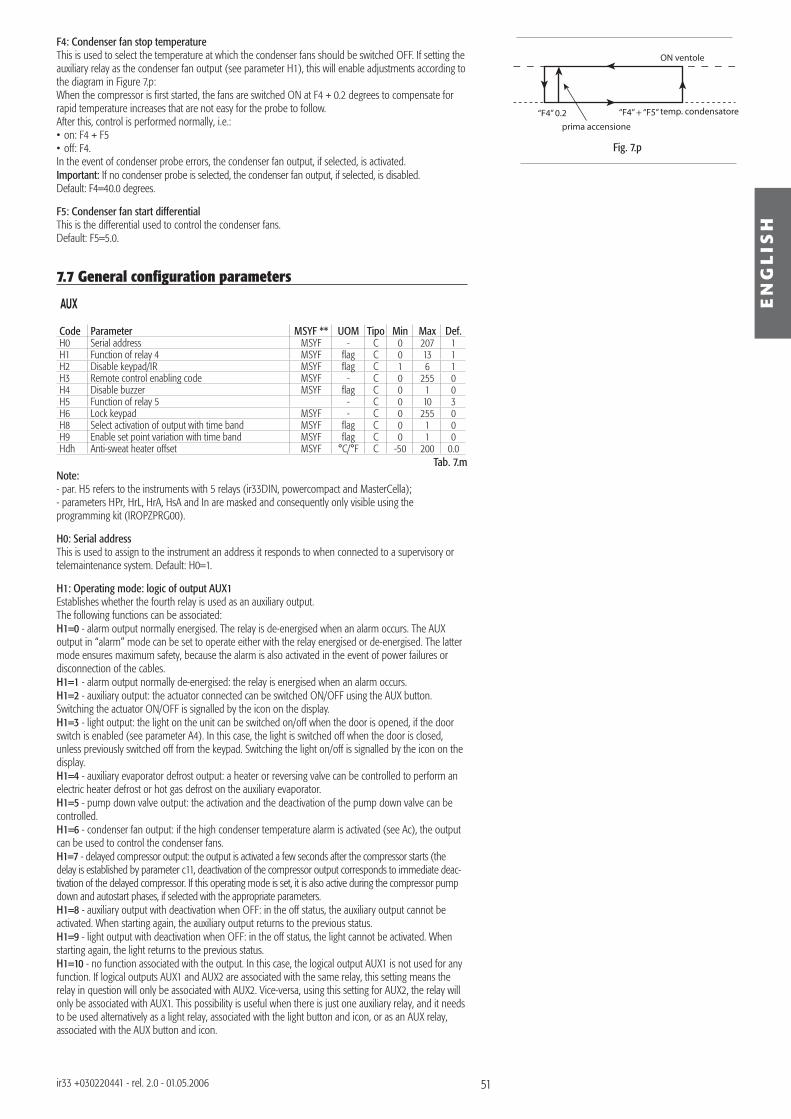
51
ON ventole
prima accensione
“F4” + “F5”“F4” 0.2 temp. condensatore
Fig. 7.p
EN
GL
ISH
ir33 +030220441 - rel. 2.0 - 01.05.2006
F4: Condenser fan stop temperatureThis is used to select the temperature at which the condenser fans should be switched OFF. If setting the auxiliary relay as the condenser fan output (see parameter H1), this will enable adjustments according to the diagram in Figure 7.p:When the compressor is fi rst started, the fans are switched ON at F4 + 0.2 degrees to compensate for rapid temperature increases that are not easy for the probe to follow.After this, control is performed normally, i.e.: • on: F4 + F5• off: F4.In the event of condenser probe errors, the condenser fan output, if selected, is activated.Important: If no condenser probe is selected, the condenser fan output, if selected, is disabled.Default: F4=40.0 degrees.
F5: Condenser fan start differentialThis is the differential used to control the condenser fans.Default: F5=5.0.
7.7 General confi guration parameters
Code Parameter MSYF ** UOM Tipo Min Max Def.H0 Serial address MSYF - C 0 207 1H1 Function of relay 4 MSYF fl ag C 0 13 1H2 Disable keypad/IR MSYF fl ag C 1 6 1H3 Remote control enabling code MSYF - C 0 255 0H4 Disable buzzer MSYF fl ag C 0 1 0H5 Function of relay 5 - C 0 10 3H6 Lock keypad MSYF - C 0 255 0H8 Select activation of output with time band MSYF fl ag C 0 1 0H9 Enable set point variation with time band MSYF fl ag C 0 1 0Hdh Anti-sweat heater offset MSYF °C/°F C -50 200 0.0
Tab. 7.mNote: - par. H5 refers to the instruments with 5 relays (ir33DIN, powercompact and MasterCella);- parameters HPr, HrL, HrA, HsA and In are masked and consequently only visible using the programming kit (IROPZPRG00).
H0: Serial addressThis is used to assign to the instrument an address it responds to when connected to a supervisory or telemaintenance system. Default: H0=1.
H1: Operating mode: logic of output AUX1Establishes whether the fourth relay is used as an auxiliary output. The following functions can be associated:H1=0 - alarm output normally energised. The relay is de-energised when an alarm occurs. The AUX output in “alarm” mode can be set to operate either with the relay energised or de-energised. The latter mode ensures maximum safety, because the alarm is also activated in the event of power failures or disconnection of the cables.H1=1 - alarm output normally de-energised: the relay is energised when an alarm occurs.H1=2 - auxiliary output: the actuator connected can be switched ON/OFF using the AUX button. Switching the actuator ON/OFF is signalled by the icon on the display. H1=3 - light output: the light on the unit can be switched on/off when the door is opened, if the door switch is enabled (see parameter A4). In this case, the light is switched off when the door is closed, unless previously switched off from the keypad. Switching the light on/off is signalled by the icon on the display.H1=4 - auxiliary evaporator defrost output: a heater or reversing valve can be controlled to perform an electric heater defrost or hot gas defrost on the auxiliary evaporator.H1=5 - pump down valve output: the activation and the deactivation of the pump down valve can be controlled.H1=6 - condenser fan output: if the high condenser temperature alarm is activated (see Ac), the output can be used to control the condenser fans.H1=7 - delayed compressor output: the output is activated a few seconds after the compressor starts (the delay is established by parameter c11, deactivation of the compressor output corresponds to immediate deac-tivation of the delayed compressor. If this operating mode is set, it is also active during the compressor pump down and autostart phases, if selected with the appropriate parameters.H1=8 - auxiliary output with deactivation when OFF: in the off status, the auxiliary output cannot be activated. When starting again, the auxiliary output returns to the previous status.H1=9 - light output with deactivation when OFF: in the off status, the light cannot be activated. When starting again, the light returns to the previous status.H1=10 - no function associated with the output. In this case, the logical output AUX1 is not used for any function. If logical outputs AUX1 and AUX2 are associated with the same relay, this setting means the relay in question will only be associated with AUX2. Vice-versa, using this setting for AUX2, the relay will only be associated with AUX1. This possibility is useful when there is just one auxiliary relay, and it needs to be used alternatively as a light relay, associated with the light button and icon, or as an AUX relay, associated with the AUX button and icon.
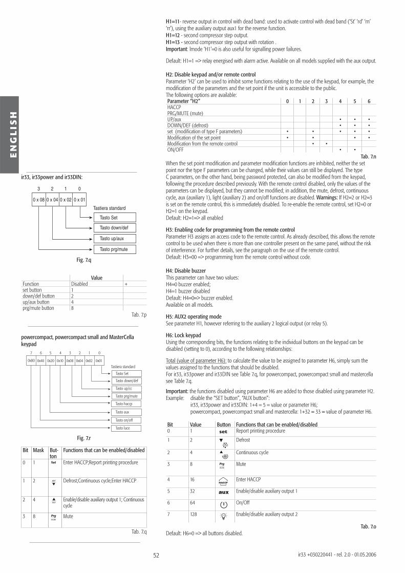
52
Fig. 7.q
0 x 08 0 x 04 0 x 02 0 x 01
3 2 1 0
Tasto Set
Tasto down/def
Tasto up/aux
Tasto prg/mute
Tastiera standard
0x08 0x04 0x02 0x01
3 2 1 0
Tasto Set
Tasto down/def
Tasto up/cc
Tasto prg/mute
Tastiera standard0x40 0x20 0x10
7 6 5 4
0x80
Tasto haccp
Tasto aux
Tasto on/off
Tasto luce
Fig. 7.r
EN
GL
ISH
ir33 +030220441 - rel. 2.0 - 01.05.2006
H1=11- reverse output in control with dead band: used to activate control with dead band (‘St’ ‘rd’ ‘rn’ ‘rr’), using the auxiliary output aux1 for the reverse function.H1=12 - second compressor step output.H1=13 - second compressor step output with rotation . Important: lmode ‘H1’=0 is also useful for signalling power failures.
Default: H1=1 => relay energised with alarm active. Available on all models supplied with the aux output.
H2: Disable keypad and/or remote controlParameter ‘H2’ can be used to inhibit some functions relating to the use of the keypad, for example, the modifi cation of the parameters and the set point if the unit is accessible to the public. The following options are available:Parameter “H2” 0 1 2 3 4 5 6HACCP PRG/MUTE (mute)UP/aux • • •DOWN/DEF (defrost) • • •set (modifi cation of type F parameters) • • • • •Modifi cation of the set point • • • •Modifi cation from the remote control • •ON/OFF • •
Tab. 7.n When the set point modifi cation and parameter modifi cation functions are inhibited, neither the set point nor the type F parameters can be changed, while their values can still be displayed. The type C parameters, on the other hand, being password protected, can also be modifi ed from the keypad, following the procedure described previously. With the remote control disabled, only the values of the parameters can be displayed, but they cannot be modifi ed; in addition, the mute, defrost, continuous cycle, aux (auxiliary 1), light (auxiliary 2) and on/off functions are disabled. Warnings: If H2=2 or H2=3 is set on the remote control, this is immediately disabled. To re-enable the remote control, set H2=0 or H2=1 on the keypad.Default: H2=1=> all enabled
H3: Enabling code for programming from the remote controlParameter H3 assigns an access code to the remote control. As already described, this allows the remote control to be used when there is more than one controller present on the same panel, without the risk of interference. For further details, see the paragraph on the use of the remote control.Default: H3=00 => programming from the remote control without code.
H4: Disable buzzerThis parameter can have two values:H4=0 buzzer enabled;H4=1 buzzer disabledDefault: H4=0=> buzzer enabled.Available on all models.
H5: AUX2 operating modeSee parameter H1, however referring to the auxiliary 2 logical output (or relay 5).
H6: Lock keypadUsing the corresponding bits, the functions relating to the individual buttons on the keypad can be disabled (setting to 0), according to the following relationships:
Total (value of parameter H6): to calculate the value to be assigned to parameter H6, simply sum the values assigned to the functions that should be disabled.For ir33, ir33power and ir33DIN see Table 7.q, for powercompact, powercompact small and mastercella see Table 7.q.
Important: the functions disabled using parameter H6 are added to those disabled using parameter H2.Example: disable the “SET button”, “AUX button”: ir33, ir33power and ir33DIN: 1+4 = 5 = value or parameter H6; powercompact, powercompact small and mastercella: 1+32 = 33 = value of parameter H6. Bit Value Button Functions that can be enabled/disabled0 1 Report printing procedure
1 2 Defrost
2 4 Continuous cycle
3 8 Mute
4 16 Enter HACCP
5 32 Enable/disable auxiliary output 1
6 64 On/Off
7 128 Enable/disable auxiliary output 2
Tab. 7.oDefault: H6=0 => all buttons disabled.
ir33, ir33power and ir33DIN:
powercompact, powercompact small and MasterCella keypad
ValueFunction Disabled +set button 1down/def button 2up/aux button 4prg/mute button 8
Tab. 7.p
Bit Mask But-ton
Functions that can be enabled/disabled
0 1 Set Enter HACCP;Report printing procedure
1 2 def Defrost;Continuous cycle;Enter HACCP
2 4aux
Enable/disable auxiliary output 1; Continuous cycle
3 8 Mute
Tab. 7.q
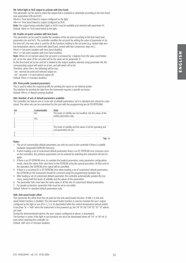
53
EN
GL
ISH
ir33 +030220441 - rel. 2.0 - 01.05.2006
H8: Select light or AUX output to activate with time band.This parameter can be used to select the output that is activated or deactivate according to the time band (see parameters tON and tOF).H8=0=> Time band linked to output confi gured as the light.H8=1=> Time band linked to output confi gured as AUX.Note: the output being controlled (light or AUX) must be available and selected with parameter H1.Default: H8=0 => Time band linked to the light.
H9: Enable set point variation with time band.This parameter can be used to enable the variation of the set point according to the time band (see parameters ton and toF). The controller modifi es the set point by adding the value of parameter r4 (to the time toF), the new value is used for all the functions relating to the set point (e.g. relative high and low temperature alarms, control with dead band, control with two compressor steps etc.). H9=0 => Set point variation with time band disabled.H9=1 => Set point variation with time band enabled.Note: When r4=3.0 (preset value) the set point is increased by 3 degrees from the value used before toF, at ton the value of the set point will be the value set for parameter St.As the time band set by ton and toF is related to the output auxiliary selected using parameter H8, the corresponding output will switch on at ton, and will switch off at toF.Therefore, when H9=1, the following will be true: - ton : normal set point and selected output on.- toF : set point + r4 and selected output off.Default: H9=0 => Function disabled.
HPr: Print profi le (masked parameter)This is used to select the required profi le for printing the report on an external printer.The interface for printing the data from the instrument requires a specifi c accessory. Default: HPr=0 => Report printing disabled.
Hdn: Number of sets of default parameters availableThe controller can feature one or more sets of default parameters. Set 0 is standard and cannot be custo-mised. The other sets can be customised by the user with the programming key kit PSOPZPGR00.
Set Customisable Note0 NO The levels of visibility are not modifi ed. Sets the values of the
visible parameters only.1 YES234 The levels of visibility and the values of all the operating and
unit parameters are set.56
Tab. 7.rNotes:1. The set of customisable default parameters can only be used on the controller if there is suitable
hardware (expanded EEPROM memory).2. If when loading a set of customised default parameters there is an EF EEPROM error (memory error
on the controller), the previous parameters can be restored by switching the instrument off and on again.
3. If there is an EF EEPROM error, to maintain the loaded parameters, enter parameter confi guration mode, check the values then save them to the EEPROM using the special procedure. At then end of the operation, the EEPROM error signal will be cancelled.
4. If there is a recurring EE or EF EEPROM error when loading a set of customised default parameters, the EEPROM on the instrument should be corrected using the programming hardware key.
5. After loading a set of customised default parameter, the controller automatically updates the me-mory, saving both the levels of visibility and the values of the parameters.
6. The parameter Hdn must have the same value in all the sets of customised default parameters.7. For greater protection, parameter Hdn must be set to not visible.Default: Hdn=0 => standard default parameters only.
Hdh: Anti-sweat heater offsetThis represents the offset from the set point for the anti-sweat heater function. If Hdh = 0, the anti-sweat heater function is disabled. The anti-sweat heater function is used to maintain the aux1 output, confi gured as the light or aux (H1= 2, 3, 8, 9) deactivated while the control temperature (virtual probe) is less than ‘St’ + ‘Hdh’ when the instrument is fi rst powered up, the ‘HI’ ‘IA’ ‘dA ‘CHt’ ‘EE’ ‘EF’ ‘rE’ alarms are reset.During the aforementioned alarms, the aux1 output, confi gured as above, is deactivated.The function is active, if the light or aux functions are set to be deactivated when off ,‘H1’ or ‘H5’=8, 9, even when switching the controller on.Default: Hdh =0.0 => function disabled.
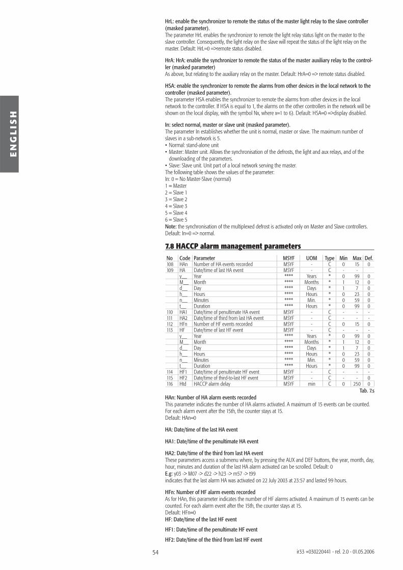
54
EN
GL
ISH
ir33 +030220441 - rel. 2.0 - 01.05.2006
HrL: enable the synchronizer to remote the status of the master light relay to the slave controller(masked parameter).The parameter HrL enables the synchronizer to remote the light relay status light on the master to the slave controller. Consequently, the light relay on the slave will repeat the status of the light relay on the master. Default: HrL=0 =>remote status disabled.
HrA: HrA: enable the synchronizer to remote the status of the master auxiliary relay to the control-ler (masked parameter)As above, but relating to the auxiliary relay on the master. Default: HrA=0 => remote status disabled.
HSA: enable the synchronizer to remote the alarms from other devices in the local network to the controller (masked parameter).The parameter HSA enables the synchronizer to remote the alarms from other devices in the local network to the controller. If HSA is equal to 1, the alarms on the other controllers in the network will be shown on the local display, with the symbol Nx, where x=1 to 6). Default: HSA=0 =>display disabled.
In: select normal, master or slave unit (masked parameter).The parameter In establishes whether the unit is normal, master or slave. The maximum number of slaves in a sub-network is 5.• Normal: stand-alone unit• Master: Master unit. Allows the synchronisation of the defrosts, the light and aux relays, and of the
downloading of the parameters.• Slave: Slave unit. Unit part of a local network serving the master.The following table shows the values of the parameter:In: 0 = No Master-Slave (normal)1 = Master2 = Slave 13 = Slave 24 = Slave 35 = Slave 46 = Slave 5Note: the synchronisation of the multiplexed defrost is activated only on Master and Slave controllers.Default: In=0 => normal.
7.8 HACCP alarm management parametersNo Code Parameter MSYF UOM Type Min Max Def.108 HAn Number of HA events recorded MSYF - C 0 15 0109 HA Date/time of last HA event MSYF - C - -
y__ Year **** Years * 0 99 0M__ Month **** Months * 1 12 0d__ Day **** Days * 1 7 0h__ Hours **** Hours * 0 23 0n__ Minutes **** Min. * 0 59 0t__ Duration **** Hours * 0 99 0
110 HA1 Date/time of penultimate HA event MSYF - C - - -111 HA2 Date/time of third from last HA event MSYF - C - - -112 HFn Number of HF events recorded MSYF - C 0 15 0113 HF Date/time of last HF event MSYF - C - - -
y__ Year **** Years * 0 99 0M__ Month **** Months * 1 12 0d__ Day **** Days * 1 7 0h__ Hours **** Hours * 0 23 0n__ Minutes **** Min. * 0 59 0t__ Duration **** Hours * 0 99 0
114 HF1 Date/time of penultimate HF event MSYF - C - - -115 HF2 Date/time of third-to-last HF event MSYF - C - - 0116 Htd HACCP alarm delay MSYF min C 0 250 0
Tab. 7.sHAn: Number of HA alarm events recordedThis parameter indicates the number of HA alarms activated. A maximum of 15 events can be counted. For each alarm event after the 15th, the counter stays at 15.Default: HAn=0
HA: Date/time of the last HA event
HA1: Date/time of the penultimate HA event
HA2: Date/time of the third from last HA eventThese parameters access a submenu where, by pressing the AUX and DEF buttons, the year, month, day, hour, minutes and duration of the last HA alarm activated can be scrolled. Default: 0E.g: y03 -> M07 -> d22 -> h23 -> m57 -> t99 indicates that the last alarm HA was activated on 22 July 2003 at 23:57 and lasted 99 hours.
HFn: Number of HF alarm events recordedAs for HAn, this parameter indicates the number of HF alarms activated. A maximum of 15 events can be counted. For each alarm event after the 15th, the counter stays at 15.Default: HFn=0HF: Date/time of the last HF event
HF1: Date/time of the penultimate HF event
HF2: Date/time of the third from last HF event
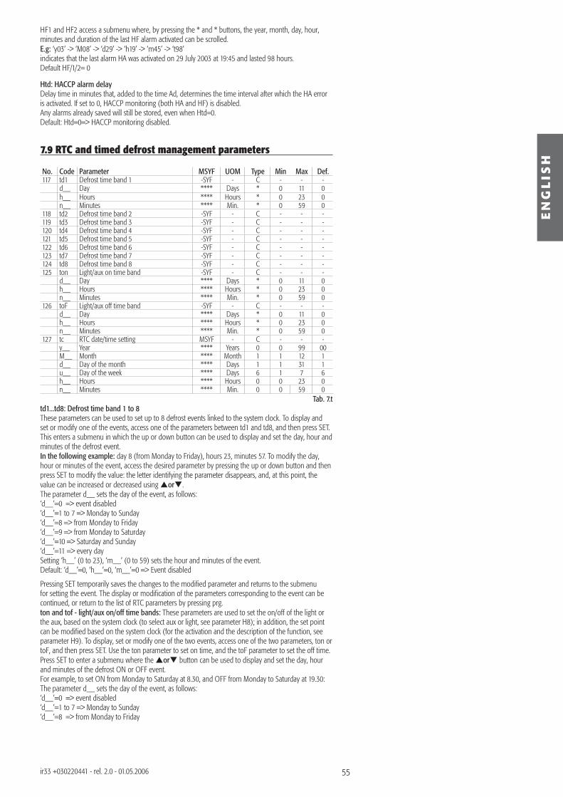
55
EN
GL
ISH
ir33 +030220441 - rel. 2.0 - 01.05.2006
HF1 and HF2 access a submenu where, by pressing the * and * buttons, the year, month, day, hour, minutes and duration of the last HF alarm activated can be scrolled.E.g: ‘y03’ -> ‘M08’ -> ‘d29’ -> ‘h19’ -> ‘m45’ -> ‘t98’indicates that the last alarm HA was activated on 29 July 2003 at 19:45 and lasted 98 hours.Default HF/1/2= 0
Htd: HACCP alarm delayDelay time in minutes that, added to the time Ad, determines the time interval after which the HA error is activated. If set to 0, HACCP monitoring (both HA and HF) is disabled.Any alarms already saved will still be stored, even when Htd=0.Default: Htd=0=> HACCP monitoring disabled.
7.9 RTC and timed defrost management parameters
No. Code Parameter MSYF UOM Type Min Max Def.117 td1 Defrost time band 1 -SYF - C - - -
d__ Day **** Days * 0 11 0h__ Hours **** Hours * 0 23 0n__ Minutes **** Min. * 0 59 0
118 td2 Defrost time band 2 -SYF - C - - -119 td3 Defrost time band 3 -SYF - C - - -120 td4 Defrost time band 4 -SYF - C - - -121 td5 Defrost time band 5 -SYF - C - - -122 td6 Defrost time band 6 -SYF - C - - -123 td7 Defrost time band 7 -SYF - C - - -124 td8 Defrost time band 8 -SYF - C - - -125 ton Light/aux on time band -SYF - C - - -
d__ Day **** Days * 0 11 0h__ Hours **** Hours * 0 23 0n__ Minutes **** Min. * 0 59 0
126 toF Light/aux off time band -SYF - C - - -d__ Day **** Days * 0 11 0h__ Hours **** Hours * 0 23 0n__ Minutes **** Min. * 0 59 0
127 tc RTC date/time setting MSYF - C - - -y__ Year **** Years 0 0 99 00M__ Month **** Month 1 1 12 1d__ Day of the month **** Days 1 1 31 1u__ Day of the week **** Days 6 1 7 6h__ Hours **** Hours 0 0 23 0n__ Minutes **** Min. 0 0 59 0
Tab. 7.ttd1...td8: Defrost time band 1 to 8These parameters can be used to set up to 8 defrost events linked to the system clock. To display and set or modify one of the events, access one of the parameters between td1 and td8, and then press SET. This enters a submenu in which the up or down button can be used to display and set the day, hour and minutes of the defrost event.In the following example: day 8 (from Monday to Friday), hours 23, minutes 57. To modify the day, hour or minutes of the event, access the desired parameter by pressing the up or down button and then press SET to modify the value: the letter identifying the parameter disappears, and, at this point, the value can be increased or decreased using or .The parameter d__ sets the day of the event, as follows: ‘d__’=0 => event disabled‘d__’=1 to 7 => Monday to Sunday‘d__’=8 => from Monday to Friday‘d__’=9 => from Monday to Saturday‘d__’=10 => Saturday and Sunday‘d__’=11 => every daySetting ‘h__’ (0 to 23), ‘m__’ (0 to 59) sets the hour and minutes of the event.Default: ‘d__’=0, ‘h__’=0, ‘m__’=0 => Event disabled
Pressing SET temporarily saves the changes to the modifi ed parameter and returns to the submenu for setting the event. The display or modifi cation of the parameters corresponding to the event can be continued, or return to the list of RTC parameters by pressing prg.ton and tof - light/aux on/off time bands: These parameters are used to set the on/off of the light or the aux, based on the system clock (to select aux or light, see parameter H8); in addition, the set point can be modifi ed based on the system clock (for the activation and the description of the function, see parameter H9). To display, set or modify one of the two events, access one of the two parameters, ton or toF, and then press SET. Use the ton parameter to set on time, and the toF parameter to set the off time.Press SET to enter a submenu where the or button can be used to display and set the day, hour and minutes of the defrost ON or OFF event.For example, to set ON from Monday to Saturday at 8.30, and OFF from Monday to Saturday at 19.30:The parameter d__ sets the day of the event, as follows: ‘d__’=0 => event disabled‘d__’=1 to 7 => Monday to Sunday‘d__’=8 => from Monday to Friday
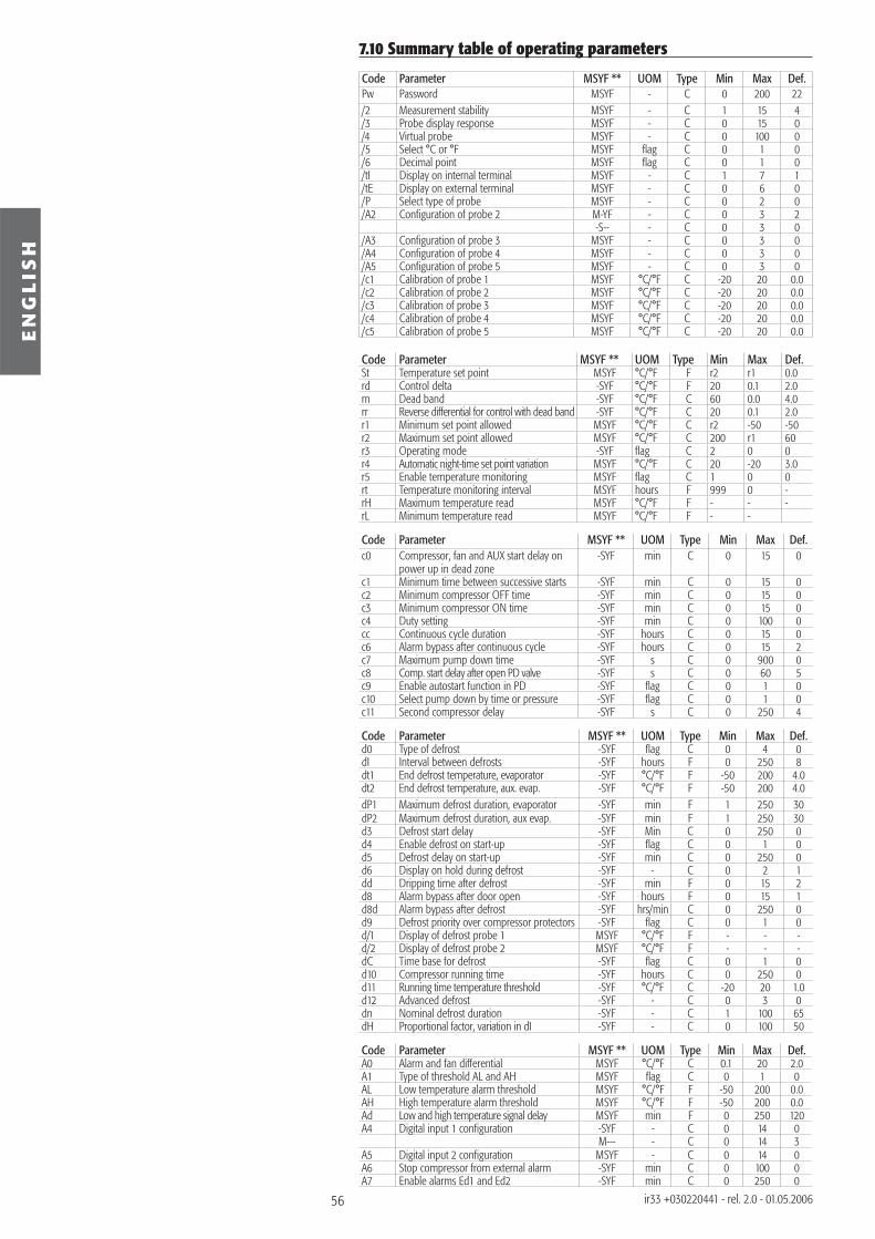
56
EN
GL
ISH
ir33 +030220441 - rel. 2.0 - 01.05.2006
7.10 Summary table of operating parameters
Code Parameter MSYF ** UOM Type Min Max Def.Pw Password MSYF - C 0 200 22/2 Measurement stability MSYF - C 1 15 4/3 Probe display response MSYF - C 0 15 0/4 Virtual probe MSYF - C 0 100 0/5 Select °C or °F MSYF fl ag C 0 1 0/6 Decimal point MSYF fl ag C 0 1 0/tI Display on internal terminal MSYF - C 1 7 1/tE Display on external terminal MSYF - C 0 6 0/P Select type of probe MSYF - C 0 2 0/A2 Confi guration of probe 2 M-YF - C 0 3 2
-S-- - C 0 3 0/A3 Confi guration of probe 3 MSYF - C 0 3 0/A4 Confi guration of probe 4 MSYF - C 0 3 0/A5 Confi guration of probe 5 MSYF - C 0 3 0/c1 Calibration of probe 1 MSYF °C/°F C -20 20 0.0/c2 Calibration of probe 2 MSYF °C/°F C -20 20 0.0/c3 Calibration of probe 3 MSYF °C/°F C -20 20 0.0/c4 Calibration of probe 4 MSYF °C/°F C -20 20 0.0/c5 Calibration of probe 5 MSYF °C/°F C -20 20 0.0
Code Parameter MSYF ** UOM Type Min Max Def.St Temperature set point MSYF °C/°F F r2 r1 0.0rd Control delta -SYF °C/°F F 20 0.1 2.0rn Dead band -SYF °C/°F C 60 0.0 4.0rr Reverse differential for control with dead band -SYF °C/°F C 20 0.1 2.0r1 Minimum set point allowed MSYF °C/°F C r2 -50 -50r2 Maximum set point allowed MSYF °C/°F C 200 r1 60r3 Operating mode -SYF fl ag C 2 0 0r4 Automatic night-time set point variation MSYF °C/°F C 20 -20 3.0r5 Enable temperature monitoring MSYF fl ag C 1 0 0rt Temperature monitoring interval MSYF hours F 999 0 -rH Maximum temperature read MSYF °C/°F F - - -rL Minimum temperature read MSYF °C/°F F - -
Code Parameter MSYF ** UOM Type Min Max Def.c0 Compressor, fan and AUX start delay on
power up in dead zone-SYF min C 0 15 0
c1 Minimum time between successive starts -SYF min C 0 15 0c2 Minimum compressor OFF time -SYF min C 0 15 0c3 Minimum compressor ON time -SYF min C 0 15 0c4 Duty setting -SYF min C 0 100 0cc Continuous cycle duration -SYF hours C 0 15 0c6 Alarm bypass after continuous cycle -SYF hours C 0 15 2c7 Maximum pump down time -SYF s C 0 900 0c8 Comp. start delay after open PD valve -SYF s C 0 60 5c9 Enable autostart function in PD -SYF fl ag C 0 1 0c10 Select pump down by time or pressure -SYF fl ag C 0 1 0c11 Second compressor delay -SYF s C 0 250 4
Code Parameter MSYF ** UOM Type Min Max Def.d0 Type of defrost -SYF fl ag C 0 4 0dI Interval between defrosts -SYF hours F 0 250 8dt1 End defrost temperature, evaporator -SYF °C/°F F -50 200 4.0dt2 End defrost temperature, aux. evap. -SYF °C/°F F -50 200 4.0dP1 Maximum defrost duration, evaporator -SYF min F 1 250 30dP2 Maximum defrost duration, aux evap. -SYF min F 1 250 30d3 Defrost start delay -SYF Min C 0 250 0d4 Enable defrost on start-up -SYF fl ag C 0 1 0d5 Defrost delay on start-up -SYF min C 0 250 0d6 Display on hold during defrost -SYF - C 0 2 1dd Dripping time after defrost -SYF min F 0 15 2d8 Alarm bypass after door open -SYF hours F 0 15 1d8d Alarm bypass after defrost -SYF hrs/min C 0 250 0d9 Defrost priority over compressor protectors -SYF fl ag C 0 1 0d/1 Display of defrost probe 1 MSYF °C/°F F - - -d/2 Display of defrost probe 2 MSYF °C/°F F - - -dC Time base for defrost -SYF fl ag C 0 1 0d10 Compressor running time -SYF hours C 0 250 0d11 Running time temperature threshold -SYF °C/°F C -20 20 1.0d12 Advanced defrost -SYF - C 0 3 0dn Nominal defrost duration -SYF - C 1 100 65dH Proportional factor, variation in dI -SYF - C 0 100 50
Code Parameter MSYF ** UOM Type Min Max Def.A0 Alarm and fan differential MSYF °C/°F C 0.1 20 2.0A1 Type of threshold AL and AH MSYF fl ag C 0 1 0AL Low temperature alarm threshold MSYF °C/°F F -50 200 0.0AH High temperature alarm threshold MSYF °C/°F F -50 200 0.0Ad Low and high temperature signal delay MSYF min F 0 250 120A4 Digital input 1 confi guration -SYF - C 0 14 0
M--- - C 0 14 3A5 Digital input 2 confi guration MSYF - C 0 14 0A6 Stop compressor from external alarm -SYF min C 0 100 0A7 Enable alarms Ed1 and Ed2 -SYF min C 0 250 0
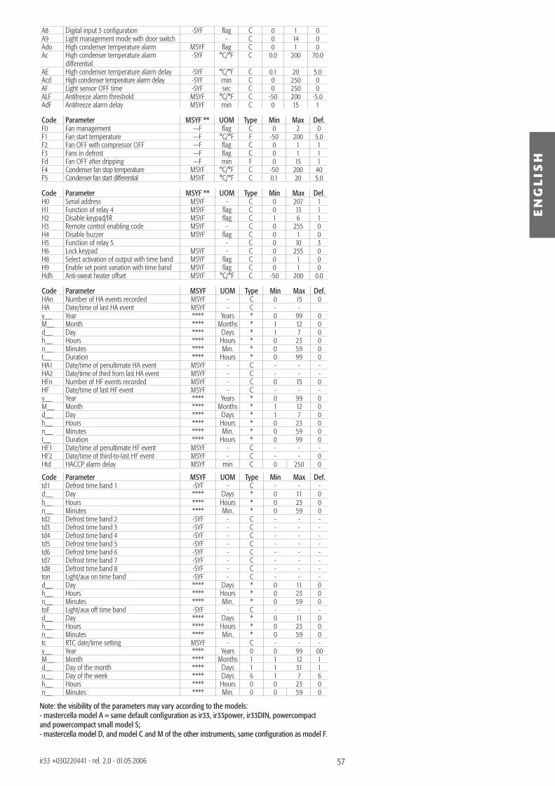
57
EN
GL
ISH
ir33 +030220441 - rel. 2.0 - 01.05.2006
A8 Digital input 3 confi guration -SYF fl ag C 0 1 0A9 Light management mode with door switch - C 0 14 0Ado High condenser temperature alarm MSYF fl ag C 0 1 0Ac High condenser temperature alarm
differential-SYF °C/°F C 0.0 200 70.0
AE High condenser temperature alarm delay -SYF °C/°F C 0.1 20 5.0Acd High condenser temperature alarm delay -SYF min C 0 250 0AF Light sensor OFF time -SYF sec C 0 250 0ALF Antifreeze alarm threshold MSYF °C/°F C -50 200 -5.0AdF Antifreeze alarm delay MSYF min C 0 15 1
Code Parameter MSYF ** UOM Type Min Max Def.F0 Fan management ---F fl ag C 0 2 0F1 Fan start temperature ---F °C/°F F -50 200 5.0F2 Fan OFF with compressor OFF ---F fl ag C 0 1 1F3 Fans in defrost ---F fl ag C 0 1 1Fd Fan OFF after dripping ---F min F 0 15 1F4 Condenser fan stop temperature MSYF °C/°F C -50 200 40F5 Condenser fan start differential MSYF °C/°F C 0.1 20 5.0
Code Parameter MSYF ** UOM Type Min Max Def.H0 Serial address MSYF - C 0 207 1H1 Function of relay 4 MSYF fl ag C 0 13 1H2 Disable keypad/IR MSYF fl ag C 1 6 1H3 Remote control enabling code MSYF - C 0 255 0H4 Disable buzzer MSYF fl ag C 0 1 0H5 Function of relay 5 - C 0 10 3H6 Lock keypad MSYF - C 0 255 0H8 Select activation of output with time band MSYF fl ag C 0 1 0H9 Enable set point variation with time band MSYF fl ag C 0 1 0Hdh Anti-sweat heater offset MSYF °C/°F C -50 200 0.0
Code Parameter MSYF UOM Type Min Max Def.HAn Number of HA events recorded MSYF - C 0 15 0HA Date/time of last HA event MSYF - C - -y__ Year **** Years * 0 99 0M__ Month **** Months * 1 12 0d__ Day **** Days * 1 7 0h__ Hours **** Hours * 0 23 0n__ Minutes **** Min. * 0 59 0t__ Duration **** Hours * 0 99 0HA1 Date/time of penultimate HA event MSYF - C - - -HA2 Date/time of third from last HA event MSYF - C - - -HFn Number of HF events recorded MSYF - C 0 15 0HF Date/time of last HF event MSYF - C - - -y__ Year **** Years * 0 99 0M__ Month **** Months * 1 12 0d__ Day **** Days * 1 7 0h__ Hours **** Hours * 0 23 0n__ Minutes **** Min. * 0 59 0t__ Duration **** Hours * 0 99 0HF1 Date/time of penultimate HF event MSYF - C - - -HF2 Date/time of third-to-last HF event MSYF - C - - 0Htd HACCP alarm delay MSYF min C 0 250 0
Code Parameter MSYF UOM Type Min Max Def.td1 Defrost time band 1 -SYF - C - - -d__ Day **** Days * 0 11 0h__ Hours **** Hours * 0 23 0n__ Minutes **** Min. * 0 59 0td2 Defrost time band 2 -SYF - C - - -td3 Defrost time band 3 -SYF - C - - -td4 Defrost time band 4 -SYF - C - - -td5 Defrost time band 5 -SYF - C - - -td6 Defrost time band 6 -SYF - C - - -td7 Defrost time band 7 -SYF - C - - -td8 Defrost time band 8 -SYF - C - - -ton Light/aux on time band -SYF - C - - -d__ Day **** Days * 0 11 0h__ Hours **** Hours * 0 23 0n__ Minutes **** Min. * 0 59 0toF Light/aux off time band -SYF - C - - -d__ Day **** Days * 0 11 0h__ Hours **** Hours * 0 23 0n__ Minutes **** Min. * 0 59 0tc RTC date/time setting MSYF - C - - -y__ Year **** Years 0 0 99 00M__ Month **** Months 1 1 12 1d__ Day of the month **** Days 1 1 31 1u__ Day of the week **** Days 6 1 7 6h__ Hours **** Hours 0 0 23 0n__ Minutes **** Min. 0 0 59 0
Note: the visibility of the parameters may vary according to the models:- mastercella model A = same default confi guration as ir33, ir33power, ir33DIN, powercompact and powercompact small model S; - mastercella model D, and model C and M of the other instruments, same confi guration as model F.
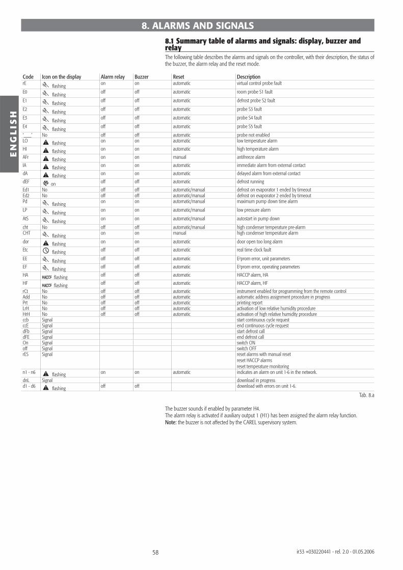
58
EN
GL
ISH
ir33 +030220441 - rel. 2.0 - 01.05.2006
8.1 Summary table of alarms and signals: display, buzzer and relayThe following table describes the alarms and signals on the controller, with their description, the status of the buzzer, the alarm relay and the reset mode.
Code Icon on the display Alarm relay Buzzer Reset DescriptionrE fl ashing on on automatic virtual control probe fault
E0 fl ashing off off automatic room probe S1 fault
E1 fl ashing off off automatic defrost probe S2 fault
E2 fl ashing off off automatic probe S3 fault
E3 fl ashing off off automatic probe S4 fault
E4 fl ashing off off automatic probe S5 fault
‘___’ No off off automatic probe not enabledLO fl ashing on on automatic low temperature alarm
HI fl ashing on on automatic high temperature alarm
AFr fl ashing on on manual antifreeze alarm
IA fl ashing on on automatic immediate alarm from external contact
dA fl ashing on on automatic delayed alarm from external contact
dEF on off off automatic defrost running
Ed1 No off off automatic/manual defrost on evaporator 1 ended by timeoutEd2 No off off automatic/manual defrost on evaporator 2 ended by timeoutPd fl ashing on on automatic/manual maximum pump down time alarm
LP fl ashing on on automatic/manual low pressure alarm
AtS fl ashing on on automatic/manual autostart in pump down
cht No off off automatic/manual high condenser temperature pre-alarmCHT fl ashing on on manual high condenser temperature alarm
dor fl ashing on on automatic door open too long alarm
Etc fl ashing off off automatic real time clock fault
EE fl ashing off off automatic E²prom error, unit parameters
EF fl ashing off off automatic E²prom error, operating parameters
HA fl ashing off off automatic HACCP alarm, HA
HF fl ashing off off automatic HACCP alarm, HF
rCt No off off automatic instrument enabled for programming from the remote controlAdd No off off automatic automatic address assignment procedure in progressPrt No off off automatic printing reportLrH No off off automatic activation of low relative humidity procedureHrH No off off automatic activation of high relative humidity procedureccb Signal start continuous cycle requestccE Signal end continuous cycle requestdFb Signal start defrost calldFE Signal end defrost callOn Signal switch ONoff Signal switch OFFrES Signal reset alarms with manual reset
reset HACCP alarmsreset temperature monitoring
n1 - n6 fl ashing on on automatic indicates an alarm on unit 1-6 in the network.
dnL Signal download in progressd1 - d6 fl ashing off off download with errors on unit 1-6.
Tab. 8.a
The buzzer sounds if enabled by parameter H4.The alarm relay is activated if auxiliary output 1 (H1) has been assigned the alarm relay function.Note: the buzzer is not affected by the CAREL supervisory system.
8. ALARMS AND SIGNALS
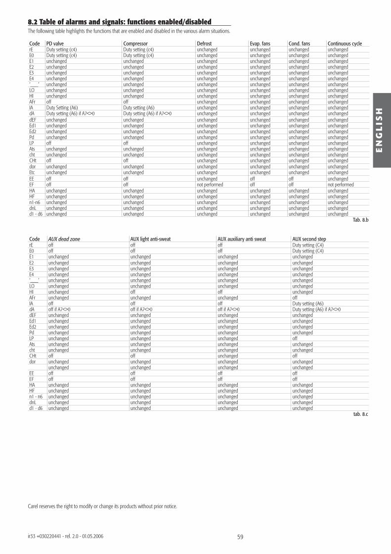
59
EN
GL
ISH
ir33 +030220441 - rel. 2.0 - 01.05.2006
8.2 Table of alarms and signals: functions enabled/disabledThe following table highlights the functions that are enabled and disabled in the various alarm situations.
Code PD valve Compressor Defrost Evap. fans Cond. fans Continuous cyclerE Duty setting (c4) Duty setting (c4) unchanged unchanged unchanged unchanged E0 Duty setting (c4) Duty setting (c4) unchanged unchanged unchanged unchanged E1 unchanged unchanged unchanged unchanged unchanged unchangedE2 unchanged unchanged unchanged unchanged unchanged unchanged E3 unchanged unchanged unchanged unchanged unchanged unchanged E4 unchanged unchanged unchanged unchanged unchanged unchanged ‘___’ unchanged unchanged unchanged unchanged unchanged unchangedLO unchanged unchanged unchanged unchanged unchanged unchangedHI unchanged unchanged unchanged unchanged unchanged unchanged AFr off off unchanged unchanged unchanged unchanged IA Duty Setting (A6) Duty setting (A6) unchanged unchanged unchanged unchanged dA Duty setting (A6) if A7<>0 Duty setting (A6) if A7<>0 unchanged unchanged unchanged unchanged dEF unchanged unchanged unchanged unchanged unchanged unchangedEd1 unchanged unchanged unchanged unchanged unchanged unchangedEd2 unchanged unchanged unchanged unchanged unchanged unchanged Pd unchanged unchanged unchanged unchanged unchanged unchanged LP off off unchanged unchanged unchanged unchanged Ats unchanged unchanged unchanged unchanged unchanged unchanged cht unchanged unchanged unchanged unchanged unchanged unchanged CHt off off unchanged unchanged unchanged unchanged dor unchanged unchanged unchanged unchanged unchanged unchangedEtc unchanged unchanged unchanged unchanged unchanged unchanged EE off off unchanged off off unchanged EF off off not performed off off not performedHA unchanged unchanged unchanged unchanged unchanged unchanged HF unchanged unchanged unchanged unchanged unchanged unchanged n1-n6 unchanged unchanged unchanged unchanged unchanged unchanged dnL unchanged unchanged unchanged unchanged unchanged unchanged d1 - d6 unchanged unchanged unchanged unchanged unchanged unchanged
Tab. 8.b
Code AUX dead zone AUX light anti-sweat AUX auxiliary anti sweat AUX second steprE off off off Duty setting (C4)E0 off off off Duty setting (C4)E1 unchanged unchanged unchanged unchanged E2 unchanged unchanged unchanged unchanged E3 unchanged unchanged unchanged unchanged E4 unchanged unchanged unchanged unchanged‘___’ unchanged unchanged unchanged unchangedLO unchanged unchanged unchanged unchangedHI unchanged off off unchangedAFr unchanged unchanged unchanged offIA off off off Duty setting (A6)dA off if A7<>0 off if A7<>0 off if A7<>0 Duty setting (A6) if A7<>0dEF unchanged unchanged unchanged unchangedEd1 unchanged unchanged unchanged unchangedEd2 unchanged unchanged unchanged unchangedPd unchanged unchanged unchanged unchangedLP unchanged unchanged unchanged offAts unchanged unchanged unchanged unchangedcht unchanged unchanged unchanged unchangedCHt off off unchanged offdor unchanged unchanged unchanged unchanged
unchanged unchanged unchanged unchangedEE off off off offEF off off off offHA unchanged unchanged unchanged unchangedHF unchanged unchanged unchanged unchangedn1 - n6 unchanged unchanged unchanged unchangeddnL unchanged unchanged unchanged unchangedd1 - d6 unchanged unchanged unchanged unchanged
tab. 8.c
Carel reserves the right to modify or change its products without prior notice.

CAREL S.p.A.Via dell’Industria, 11 - 35020 Brugine - Padova (Italy)Tel. (+39) 049.9716611 - Fax (+39) 049.9716600e-mail: [email protected] - www.carel.com
Agenzia / Agency:
+030
2204
41 r
el. 2
.0 -
01.0
5.20
06
![OPTYMA™ kondenseringsaggregater - Schløsser Møller ... · El karakteristik = 10 K overophedet Aggregat LRA kompressor [A] MCC kompressor [A] MCC blæser [A] 400 V/ 3 fase 230](https://static.documents.pub/doc/80x56/5c9054da09d3f23a138d1a4e/optyma-kondenseringsaggregater-schlosser-moller-el-karakteristik.jpg)


