(3) Situation of Fukushima Dai-ni Nuclear Power Station 1) Outline of Fukushima Dai-ni Nuclear Power Station Fukushima Dai-ni Nuclear Power Station (NPS) is located in the towns of Tomioka and Naraha in Futaba County in Fukushima Prefecture, about 12 km south of Fukushima Dai-ichi NPS, and faces the Pacific in the east. The shape of the site is roughly square and the total site area is about 1.47 million m 2 (Fig. II-2-84). Since the commissioning of Unit 1 in April 1982, Fukushima Dai-ni NPS gradually extended its facilities, and at present it consists of a total of four reactors, with a total generating capacity of 4,400 MW (Table II-2-38). TableII-2-38 Power Generation Facilities of Fukushima Dai-ni NPS Unit 1 Unit 2 Unit 3 Unit 4 Electric output (10,000 kW) 110.0 110.0 110.0 110.0 Start of construction 1975/11 1979/2 1980/12 1980/12 Commercial operation 1982/4 1984/2 1985/6 1987/8 Reactor type BWR-5 Containment type Mark II Improved Mark II Number of fuel assemblies 764 764 764 764 Number of control rods 185 185 185 185 Figure II-2-84 General Arrangement Plan of Fukushima Daini Nuclear Power Station Unit 4 Unit 3 Unit 2 Unit 1 Chapter II II-220
Transcript
(3) Situation of Fukushima Dai-ni Nuclear Power Station
1) Outline of Fukushima Dai-ni Nuclear Power Station
Fukushima Dai-ni Nuclear Power Station (NPS) is located in the towns of Tomioka and
Naraha in Futaba County in Fukushima Prefecture, about 12 km south of Fukushima
Dai-ichi NPS, and faces the Pacific in the east. The shape of the site is roughly square
and the total site area is about 1.47 million m2
(Fig. II-2-84). Since the commissioning
of Unit 1 in April 1982, Fukushima Dai-ni NPS gradually extended its facilities, and at
present it consists of a total of four reactors, with a total generating capacity of 4,400
MW (Table II-2-38).
TableII-2-38 Power Generation Facilities of Fukushima Dai-ni NPS
Unit 1 Unit 2 Unit 3 Unit 4
Electric output
(10,000 kW) 110.0 110.0 110.0 110.0
Start of construction 1975/11 1979/2 1980/12 1980/12
Commercial operation 1982/4 1984/2 1985/6 1987/8
Reactor type BWR-5
Containment type Mark II Improved Mark II
Number of fuel
assemblies 764 764 764 764
Number of control rods 185 185 185 185
Figure II-2-84 General Arrangement Plan of Fukushima Daini Nuclear Power Station
1号機
2号機
3号機
4号機 Unit 4
Unit 3
Unit 2
Unit 1
Chapter II
II-220
2) Safety design against design basis events at Fukushima Dai-ni NPS
Safety design of the external power supply, emergency power supply system and
cooling functions, etc. against design basis events at Fukushima Dai-ni NPS, as related
to the recent accident, is as follows.
The external power supply is designed to be connected to the electric power system
through two or more lines. Concerning the emergency power supply system responding
to a loss of external power supply, emergency DGs are installed based on the concept of
redundancy and independence. In addition to this, an emergency DC power supply
system (batteries) is installed in order to address the short-term loss of all AC power
supplies, and thus redundancy and independence have been secured.
High pressure core spray systems (HPCS) and RCIC are also installed as systems to
cool down the core under high pressure condition, in case cooling by a condenser
cannot be achieved. In addition, RHR and low pressure core spray systems (LPCS) are
installed as systems to cool down the core under low pressure condition.
Further, SRV is installed in the main steam pipe connecting to the RPV in order to
discharge reactor steam to S/C. The SRV has a function of automatic de-pressurization.
A comparison of these safety facilities is shown in Table II-2-39, and the system
configuration is shown in Figures II-2-85 to II-2-105.
Seawater supplied by the seawater cooling system is used as the ultimate heat sink at the
heat exchangers in RHR, as is shown in Figures II-2-94 to II-2-102.
For the prevention of hydrogen explosions, a nitrogen atmosphere is maintained inside
the PCV, and a flammable gas control system (FCS) is installed in order to prevent
hydrogen combustion inside the PCV.
Chapter II
II-221
Table II-2-39 Comparison of Engineering Safety Equipment and Reactor
Auxiliary Equipment
Unit 1 Unit 2 Unit 3 Unit 4
Number of systems 1 1 1 1
Flow rate
Unit 1 flow rate(t/h)Units 2-4 pumping rate (t/h)
Total pump head (m) 866~197 Approx.860~Approx.200
Number of pumps 1 1 1 1
Number of systems 1 1 1 1
Flow rate
Unit 1 flow rate(t/h)Units 2-4 pumping rate (t/h)
Total pump head(m) 218 Approx.210 Approx.210 Approx.210
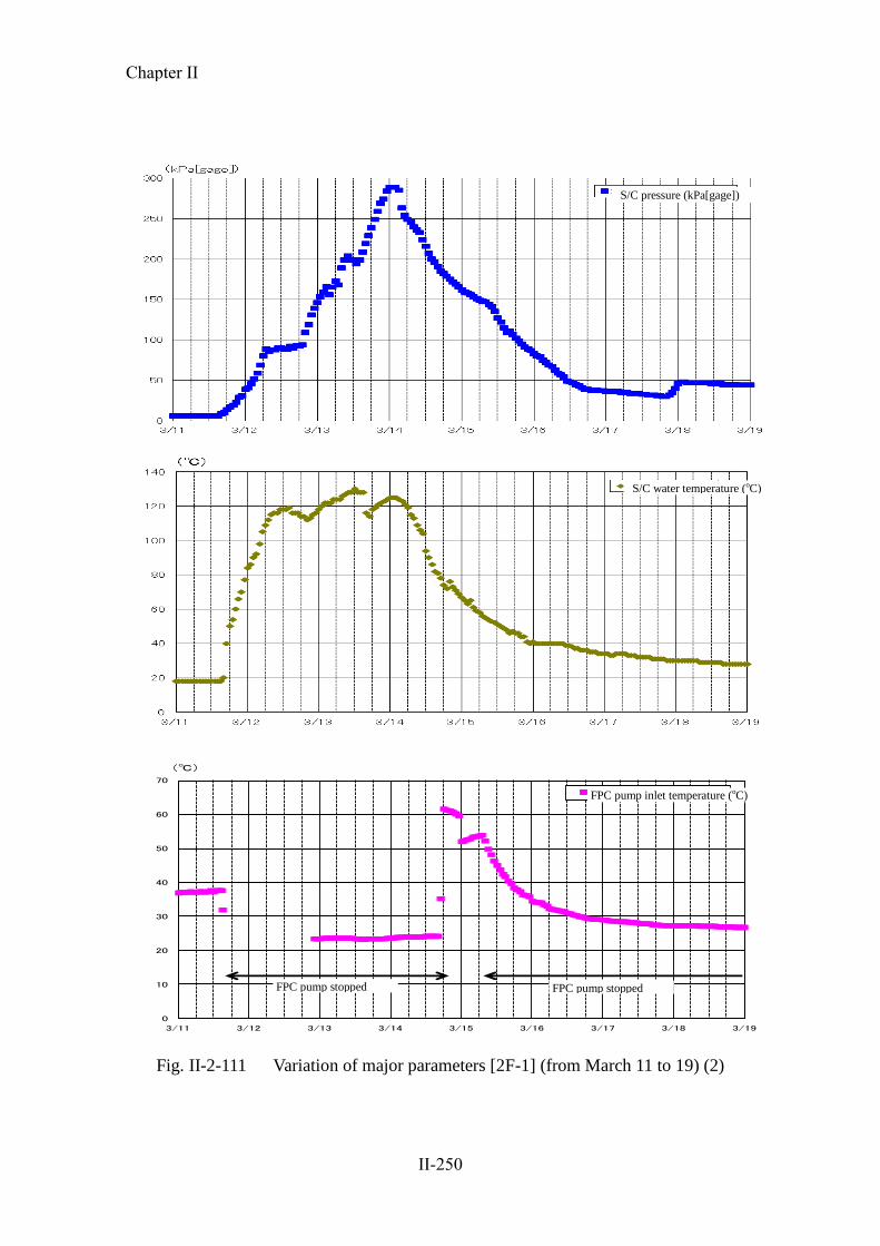
water was injected into the S/C via the SRV, secondly, S/C water was cooled by the
Chapter II
II-240
RHR heat exchanger (B) and thirdly, cooled S/C water was injected into the reactor
again through the LPCI line. As a result, the reactor water temperature fell below
100oC at 17:00, and it was confirmed that Unit 1 reached cold shutdown status.
Spent fuel pool
The FPC pump tripped due to the influence of the earthquake (“skimmer surge tank
water level low-low” or “pump’s suction pressure low”). Also, the seawater (SW)
system pumps (A, B and C) of the non-safety service water system were inundated,
and the RCW pumps (A, B and C) on the first basement in the seawater heat
exchanger building were submerged. As these pumps became inoperable and unable
to provide cooling water into the FPC heat exchanger, cooling of the SFP by FPC
could no longer be achieved.
As a result, the SFP temperature rose as high as 62oC at its peak. Water injection
into the SFP through the fuel pool make-up water (FPMUW) system started at
16:30 on March 14. Then, cooling of the SFP by circulating the injected water
started at 20:26 on the same day by the FPC pump (B). Subsequently, cooling of
SFP by the RHR pump (B) started at 0:42 on March 16, and finally at 10:30 on the
same day, the SFP temperature returned to about 38oC, which was the level before
the occurrence of the earthquake.
Containment function
The reactor containment isolation system (hereinafter referred to as “PCIS”) and the
SGTS functioned properly in response to the “reactor water level low (L-3)” signal,
generated at the time when the reactor was scrammed automatically by the “seismic
acceleration high” trip signal at 14:48 on March 11, and the PCV was isolated and
atmospheric pressure inside the reactor building was maintained. Although the PCV
pressure reached as high as about 282kPa gage (on the S/C side) at its peak, it did
not reach the maximum operating pressure of 310kPa gage.
Based on the fact that the PCV pressure was on an upward trend, and assuming that
it would take time to restore the reactor heat removal function, a line configuration
for a PCV pressure resistance ventilation system (a status where the action to open
the outlet valve on the S/C side remained available) was set up.
On-site power supply system
Chapter II
II-241
Immediately after the reactor scram, all on-site power supply systems were
operable. However, due to the subsequent tsunamis, the emergency power supply
system (M/C 1C and 1HPCS) became inoperable because of the submergence of
the reactor building annex, and the emergency power supply system (P/C 1C-2 and
1D-2) became inoperable because of the submergence of the seawater heat
exchanger building. MCC 1C-1-8 lost power because of the inoperability of M/C
1C, and the vital AC 120V power supply distribution board 1A, which had been its
load, shut down and thereby some recorders, etc. became inoperable in the main
control room.
Emergency DGs (A and B systems, and HPCS system) were all operable
immediately after the reactor scram. However, after the tsunami strike, all the
emergency equipment cooling water system pumps failed to be actuated.
Furthermore, as the reactor building annex was submerged due to tsunamis, the
main bodies of the emergency DGs and their accessories (such as pumps, control
panels, MCCs) were inundated, and thus all the emergency DGs became
inoperable.
In the course of the subsequent restoration, the AC 120V vital power supply
distribution board 1A succeeded in receiving power through temporary cables
installed from the temporary power supply distribution board at Unit 2 and became
operable (with restoration work conducted on March 12). Among the load supplied
to the inoperable emergency power supply (P/C 1D-2), RHRC pump (D) and RHRS
pump (B), required for cooling down the reactor and the SFP, secured the power
supply through temporary cables installed from the power supply system of the
radioactive waste treatment building (P/C 1WB-1), and EECW pump (B) secured
the power from a high voltage power supply vehicle (with restoration work
conducted on March 13 and 14).
The main time-series data is shown in Table II-2-40. Statuses of ECCS components,
etc. are shown in Table II-2-41. A schematic view of the plant status is shown in
Figures II-2-107 and 108. The status of the single-line diagram is shown in Figure
II-2-109. Changes in major parameters are shown in Figures II-2-110 and 111.
Chapter II
II-242
Table II-2-40 Fukushima Dai-ni NPS, Unit 1 – Main Chronology (provisional)
* The information included in the table is subject to modifications following later verifications. The
table was established based on the information provided by TEPCO, but it may include unreliable
information due to tangled process of collectinginformation amid the emergency response. As for the view of the Government of Japan, it is expressed in the body text of the report.
3/11 14:46 Earthquake occurred
14:48 All control rods inserted
Automatic reactor shutdown (Trip caused by large earthquake acceleration)
Automatic turbine shutdown
One circuit of Tomioka Line went down (Line 2 tripped, while Line 1 continued receiving electricity)
15:00 Subcritical reactor confirmed
15:22 First wave of tsunami observed (Subsequently, tsunami was observed intermittently until 17:14)
15:33 Circulating water pump (CWP) (C) manually stopped
15:34 Emergency diesel generator (emergency DG) (A) (B) (H) started automatically/immediately stopped due to the impact of tsunami
15:36 Main steam isolation valve (MSIV) closed manually
Reactor core isolation cooling system (RCIC) started manually (Subsequently, start and stop occurred as appropriate)
15:50 Iwaido Line completely went down (Line 2 went down, while Line 1 has already been down for maintenance since before the earthquake)
15:55 Started reactor depressurization (Safety relief valve (SRV) opened automatically) (Subsequently the reactor pressure controlled by automatic or manual opening/closing)
15:57 CWP (A) (B) automatically stopped
17:35 "High Dry Well Pressure" alarm issuedOperator determined that an event to be reported according to Article 10 of the Act on Special Measures concerning Nuclear Emergency Preparedness (reactor coolant leakage) had occurred
(At 18:33, Operator determined that the event was not the reactor coolant leakage)
17:53 Dry well (D/W) cooling system started manually
18:33 Operator determined that an event to be reported according to Article 10 of the Act on Special Measures concerning Nuclear Emergency Preparedness (loss of reactor heat removal function) had occurred
3/12 0:00 Alternative injection using condensate water makeup system (MUWC) started3:50 Started rapid reactor depressurization (Because the heat capacity exceeded the allowable range for operation)
4:56 Completed rapid reactor depressurization
4:58 RCIC stopped manually (Shutdown due to the pressure drop of reactor)
5:22 As the water temperature in the suppression chamber (S/C) exceeded 100℃, Operator determined that an event to be reported according to Article 15 of the Act on Special Measures concerning Nuclear Emergency Preparedness (loss of pressure control function) had occurred
5:58 "Abnormal 10-51 PIP Control Rod" alarm issued
6:20 S/C cooling performed using flammability control system (FCS) cooling water (MUWC)
7:10 D/W spray performed using MUWC (Subsequently it was done as appropriate)
7:37 S/C spray performed using MUWC (Subsequently it was done as appropriate)
7:45 Completed S/C cooling using FCS cooling water (MUWC)
10:21 Started configuration of pressure-proof vent line for reactor containment vessel (PCV)
10:30 "Abnormal 10-51 PIP Control Rod" alarm cleared (Subsequently, issued/cleared several times)Around13:38 One circuit of Iwaido Line received electricity (Line 2 finished recovery)
18:30Completed configuration of PCV pressure-proof vent line
3/13 Around 5:15 Two circuits of Iwaido Line received electricity (Line 1 finished recovery)
20:17 Manually started residual heat removal and cooling seawater system (RHRS) pump (B) (A temporary cable laid down
from 480V standby low voltage switchboard (power center (P/C)) IWB-1, in order to receive electricity)
21:03 Manually started residual heat removal and cooling system (RHRC) pump (D) (Motor replaced/A temporary cable laid down from P/C IWB-1, in order to receive electricity)
3/14 1:24 Manually started residual heat removal system (RHR) (B) (Started S/C cooling mode) As the RHR (B) started, Operator determined that the condition
deemed as an event to be reported according to Article 10 of the Act on Special Measures concerning Nuclear Emergency Preparedness (loss of reactor heat removal function) had become normal
1:44 Manually started emergency equipment cooling system (EECW) (B) (Motor replaced/Received electricity from high voltage power supply vehicle)
3:39 Started RHR (B) S/C spray mode10:05 Started water injection to reactor by RHR (B) low-pressure injection (LPCI) mode10:15 As the S/C water temperature dropped below 100℃, Operator determined that the condition deemed as an event to be reported according to Article 15 of the Act on
Special Measures concerning Nuclear Emergency Preparedness (loss of pressure control function) had become normal
16:30 Started water injection to spent fuel pool (SFP) using fuel pool makeup water system (FPMUW)
17:00 As the reactor water temperature dropped below 100℃, the reactor was put into a state of cold shutdown
20:26 Started circulation operation of fuel pool cooling and purification system (FPC) (B)
22:07 Because Monitoring Post No.1 measured radiation dose in excess of 5 μGy/h (at 0:12 on March 15, Monitoring Post No.3 also measured), Operator determined that an event to be reported
according to Article 10 of the Act on Special Measures concerning Nuclear Emergency Preparedness (increase of radiation dose on the site boundary) had occurred
(It is estimated that the increase in dose was caused by the effect of radioactive material released into the atmosphere due to the accident in Fukushima Daiichi Nuclear Power Station)
3/15
3/16 0:42 Started SFP cooling using RHR (B)
10:30 SFP water temperature became about 38℃ (Returned to water temperature before the earthquake)
3/17 17:22 PCV vent ready state restored to normal state
3/18
3/19 15:28 Stopped RHR (B) (For inspection of pumps in RHRC system)
3/20 22:14 Started RHR (B)
3/21
3/223/23
3/24
3/25
3/26
3/27
3/28
3/29
3/30 10:34 Stopped RHR (B) (For construction of a temporary power supply)RHR(B)
14:30 Started RHR (B)
17:56 Smoke was detected at the power supply board on the first floor of turbine building
18:13 After the electricity supply was turned off, the smoke went out.
19:15 It was determined that the smoke from the power supply board had been caused by the defect of the board, not fire
3/31
4/1 13:43 Stopped RHR (B) (For intake inspection)
15:07 Started RHR (B)
4/2
Fukushima Dai-ni Nuclear Power Station
Unit 1Status before earthquake: In operation
Chapter II
II-243
4/3
4/4
4/5
4/6
4/7
4/8
4/9
4/10
4/11
4/124/13
4/14
4/15 Around 17:43 Two circuits of Tomioka Line received electricity (Line 2 restored)
5/27 10:01 Fire occurred from the lighting panel board for HPCS M/C room in the attached wing to the reactor building
10:04 Field workers extinguished the fire and a person on duty confirmed
11:19 After the extinction, it was determined as a small fire in the building
7/7 Around 14:05 Sparks were found at a connection breaker between M/C HPCS and M/C 1SB-2M/C
17:37 Stopped RHR pump (B)
17:44 Released the connection breaker and started inspection
21:15 Started RHR pump (B)
7/17 9:36 Stopped RHR (B) (For changing cooling mode, from LPCI mode to reactor shutdown cooling (SHC) mode)
11:04 Started SFP cooling using FPC
14:13 Started RHR (B)
8/31
Chapter II
II-244
Table II-2-41 Status of Emergency Core Cooling System Equipment etc.[2F-1]
Installed
place
Seismic
class
When the
reactor
scrammed
Till just before
tsunami arrived
after rector scram
Till cold
shutdown
after
tsunami
arrival
Remarks
Cooling
Function
ECCS etc.
RHR(A) R/B 2nd
basement (o.p.0000)
A ○ ○ ×
Unavailable because power supply equipment was submerged and RHRS, RHRC and EECW became unoperable due to tsunami. No damage on the pump body
LPCS R/B 2nd
basement (o.p.0000)
A ○ ○ ×
Unavailable because power supply equipment was submerged and RHRS, RHRC and EECW became unoperable due to tsunami. No damage on the pump body
RHRC(A) Hx/B 1st
floor (o.p.4200)
A ○ ○ × Unavailable because power supply equipment and motor was submerged and unopearble due to tsunami
RHRC(C) Hx/B 1st
floor (o.p.4200)
A ○ ○ × Unavailable because power supply equipment and motor was submerged and unopearble due to tsunami
RHRS(A) Hx/B 1st
floor (o.p.4200)
A ○ ◎ × Unavailable because power supply equipment was submerged due to tsunami. No damage on the pump body
RHRS(C) Hx/B 1st
floor (o.p.4200)
A ○ ◎ × Unavailable because power supply equipment was submerged due to tsunami. No damage on the pump body
EECW(A) Hx/B 1st
floor (o.p.4200)
A ○ ◎ × Unavailable because power supply equipment and motor was submerged and unoperable due to tsunami
RHR(B) R/B 2nd
basement (o.p.0000)
A ○ ○ ×→◎
Unavailable because RHRS, RHRC and EECW became unoperable due to tsunami. No damage on the pump body. Started operation after recovery of RHRS, RHRC and EECW on Mar. 14
RHR(C) R/B 2nd
basement (o.p.0000)
A ○ ○ ×→○
Unavailable because RHRS, RHRC and EECW became unoperable due to tsunami. No damage on the pump body. Became stnadby after recovery of RHRS, RHRC and EECW on Mar. 14
RHRC(B) Hx/B 1st
floor (o.p.4200)
A ○ ◎ × Unavailable because power supply equipment and motor was submerged and unoperable due to tsunami
RHRC(D) Hx/B 1st
floor (o.p.4200)
A ○ ◎ ×→◎
Unavailable because power supply equipment and motor was submerged and unoperable due to tsunami. Temporary cabling from RW/B and started operation after motor replacement on Mar. 13
RHRS(B) Hx/B 1st
floor (o.p.4200)
A ○ ◎ ×→◎
Unavailable because power supply equipment was submerged and unoperable due to tsunami. Temporary cabling from RW/B and started operation after motor replacement on Mar. 13
RHRS(D) Hx/B 1st
floor (o.p.4200)
A ○ ◎ × Unavailable because power supply equipment was submerged due to tsunami. No damage on the pump body
EECW(B) Hx/B 1st
floor (o.p.4200)
A ○ ◎ ×→◎
Unavailable because power supply equipment and motor was submerged due to tsunami. Temporary cabling from high voltage power supply vehicle and started operation after motor replacement on Mar. 13
HPCS R/B 2nd
basement (o.p.0000)
A ○ ○ ×
Unavailable because power supply equipment was submerged and HPCSS and HPCSC became unoperable due to tsunami. No damage on the pump body
HPCSC Hx/B 1st
floor (o.p.4200)
A ○ ○ × Unavailable because power supply equipment was submerged due to tsunami. No damage on the pump body
HPCSS Hx/B 1st
floor (o.p.4200)
A ○ ○ × Unavailable because power supply equipment was submerged due to tsunami. No damage on the pump body
Water
Injection
to
Reactor
RCIC R/B 2nd
basement (o.p.0000)
A ○ ◎ ◎→○ Started operation after tsunami and stopped due to reactor pressure drop on Mar. 12.
MUWC
(Alternative
Injection)
T/B 1st basement (o.p.2400)
B ○ ○ ○→◎→○
Operated on Mar. 12 and became standby on Mar. 14. For (a) and (c), unavailable because power supply equipment was submerged due to tsunami.
Pool
Cooling
SFP Cooling
(FPC)
R/B 4th floor (o.p.33000) B ◎ × ×
Unavailable because of trip by earthequake and RCW out of operation due to tsunami. Started water injection by FPMUW pump and circulation by FPC pump. Started cooling by FPC on Mar. 14.
SFP Cooling
(RHR)
R/B 2nd basement (o.p.0000)
A ○ ○ ×→◎
Unavailable because RHRS, RHRC and EECW was unoperable due to tsunami. Started operation after recovery of RHRS, RHRC and EECW on Mar. 16.
Confine-
ment
Function
Cantain-
ment
Facility
Reactor
Building A ○ ○ ○
Maintain negative pressure and observed no sign of damage.
Primary
Containment
Vessel
As ○ ○ ○
Observe no sign of damage regarding PCV presuure
(Legend) ◎:in operation ○:stand by ×:Loss of Function or Outage
Chapter II
II-245
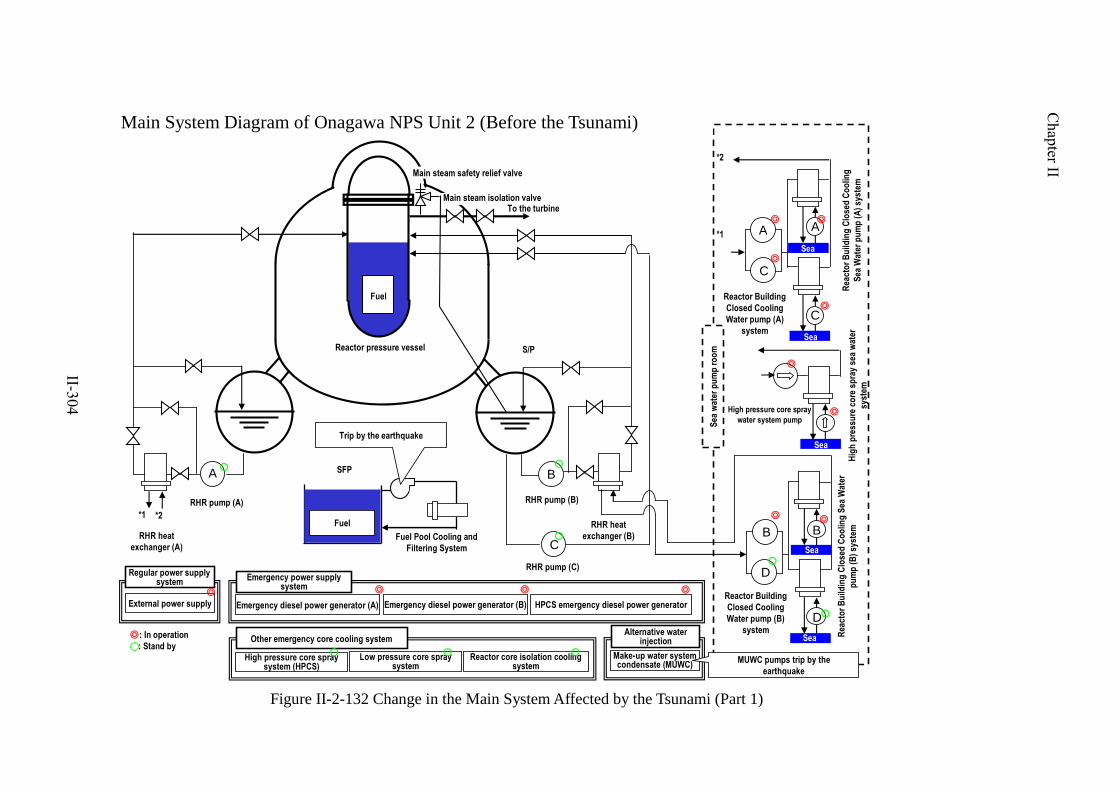
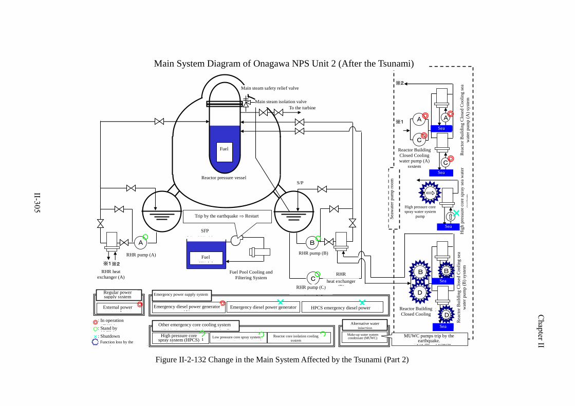
Figure II-2-107 Schematic Diagram of Station Status [2F-1] (Part 1)
Table II-2-43 Status of Emergency Core Cooling System Equipment etc.[2F-2]
Installed
place
Seismic
class
When the
reactor
scrammed
Till just before
tsunami arrived
after rector scram
Till cold
shutdown
after
tsunami
arrival
Remarks
Cooling
Function
ECCS etc.
RHR(A) R/B 2nd
basement (o.p.0000)
A ○ ○ × Unavailable because RHRS, RHRC and EECW became unoperable due to tsunami. No damage on the pump body
LPCS R/B 2nd
basement (o.p.0000)
A ○ ○ × Unavailable because RHRS, RHRC and EECW became unoperable due to tsunami. No damage on the pump body
RHRC(A) Hx/B 2nd
floor (o.p.11200)
A ○ ○ ×
Unavailable because power supply equipment and motor was submerged and unopearble due to tsunami. No damage on the pump body
RHRC(C) Hx/B 2nd
floor (o.p.11200)
A ○ ○ ×
Unavailable because power supply equipment and motor was submerged and unopearble due to tsunami. No damage on the pump body
RHRS(A) Hx/B 1st
floor (o.p.4200)
A ○ ○ × Unavailable because power supply equipment and motor was submerged and unoperable due to tsunami
RHRS(C) Hx/B 1st
floor (o.p.4200)
A ○ ○ × Unavailable because power supply equipment and motor was submerged and unoperable due to tsunami
EECW(A) Hx/B 1st
floor (o.p.4200)
A ○ ◎ × Unavailable because power supply equipment and motor was submerged and unoperable due to tsunami
RHR(B) R/B 2nd
basement (o.p.0000)
A ○ ◎ ×→◎
Unavailable because RHRS, RHRC and EECW became unoperable due to tsunami. No damage on the pump body. Started operation after recovery of RHRS, RHRC and EECW on Mar. 14
RHR(C) R/B 2nd
basement (o.p.0000)
A ○ ○ ×→○
Unavailable because RHRS, RHRC and EECW became unoperable due to tsunami. No damage on the pump body. Became standby after recovery of RHRS, RHRC and EECW on Mar. 14
RHRC(B) Hx/B 2nd
floor (o.p.11200)
A ○ ◎ ×→◎
Unavailable because power supply equipment and motor was submerged and unoperable due to tsunami. No damage on the pump body. Temporary cabling from RW/B and started operation on Mar. 13
RHRC(D) Hx/B 2nd
floor (o.p.11200)
A ○ ◎ ×
Unavailable because power supply equipment was submerged and unoperable due to tsunami. No damage on the pump body.
RHRS(B) Hx/B 1st
floor (o.p.4200)
A ○ ◎ ×→◎
Unavailable because power supply equipment was submerged and unoperable due to tsunami. No damage on the pump body. Temporary cabling from RW/B and started operation on Mar. 13
RHRS(D) Hx/B 1st
floor (o.p.4200)
A ○ ◎ × Unavailable because power supply equipment and motro was submerged and unoperable due to tsunami.
EECW(B) Hx/B 2nd
floor (o.p.11200)
A ○ ◎ ×→◎
Unavailable because power supply equipment was submerged and unoperable due to tsunami. No damage on the pump body. Temporary cabling from Hx/B of Unit 3 and started operation on Mar. 14
HPCS R/B 2nd
basement (o.p.0000)
A ○ ○ × Unavailable because HPCSC was submerged and unoperable due to tsunami. No damage on the pump body
HPCSC Hx/B 1st
floor (o.p.4200)
A ○ ◎ × Unavailable because motor was submerged and unoperable due to tsunami.
HPCSS Hx/B 1st
floor (o.p.4200)
A ○ ◎ ○
Water
Injection
to
Reactor
RCIC R/B 2nd
basement (o.p.0000)
A ○ ◎ ◎→○ Started operation after tsunami and stopped due to reactor pressure drop on Mar. 12.
MUWC
(Alternative
Injection)
T/B 1st basement (o.p.2400)
B ○ ○ ○→◎→○
Operated on Mar. 12 and became standby on Mar. 14.
Pool
Cooling
SFP Cooling
(FPC)
R/B 4th floor (o.p.31800) B ◎ × ×
Unavailable because of trip by earthequake and RCW out of operation due to tsunami. Started operation on Mar. 16.
SFP Cooling
(RHR)
R/B 2nd basement (o.p.0000)
A ○ ○ ×→◎
Unavailable because RHRS, RHRC and EECW was unoperable due to tsunami. Started operation after recovery of RHRS, RHRC and EECW on Mar. 16 (FPC Auxiliary Coolig Mode).
Confine-
ment
Function
Cantain-
ment
Facility
Reactor
Building A ○ ○ ○
Maintain negative pressure and observed no sign of damage.
Primary
Containment
Vessel
As ○ ○ ○
Observe no sign of damage regarding PCV presuure
(Legend) ◎:in operation ○:stand by ×:Loss of Function or Outage
Chapter II
II-258
Figure II-2-112 Schematic Diagram of Station Status [2F-2] (Part 1)
Fig. II-2-115 Variation of major parameters [2F-2] (from March 11 to 19) (1)
Beyond scale
Reactor level (wide range) (mm)
Reactor pressure (MPa[gage])
Chapter II
II-262
0
10
20
30
40
50
60
70
3/11 3/12 3/13 3/14 3/15 3/16 3/17 3/18 3/19
燃料プール表面温度(℃)
FPCポンプ入口温度(℃)
(℃)
FPCポンプ停止
温度計測不良
Fig. II-2-116 Variation of major parameters [2F-2] (from March 11 to 19) (2)
S/C pressure (kPa[gage])
S/C water temperature (oC)
Fuel pool surface temperature (oC)
FPC pump inlet temperature (oC)
Temperature measurrment unavailable
FPC pump stopped
Chapter II
II-263
c Fukushima Dai-ni NPS Unit 3
Overall conditions immediately after the occurrence of the earthquake
The reactor, which had been under operation at its rated thermal power, was
scrammed automatically at 14:48 on March 11, immediately after the occurrence of
the earthquake, due to excessive seismic acceleration. All the control rods were
fully inserted and the reactor was scrammed properly. It was confirmed at 15:05 on
March 11 that the reactor became subcritical.
Immediately after the reactor scram, voids in the reactor core decreased and the
reactor water level declined to as low as the “reactor water level low (L-3).” After
that, the reactor water level was recovered by water supplied from the reactor feed
water system without further declining to the level at which the ECCS pump and
RCIC automatically actuate.
At 15:37 on March 11, the MSIV was fully closed manually so that the reactor
pressure could be controlled by the SRV in preparation for the situations that the
CWP stopped due to the influence of the tsunamis and the resulting inability to
condensate main steam by the condenser, and also that the turbine gland seal steam
was lost caused by the shutdown of the auxiliary boilers due to the influence of the
earthquake.
In association with the complete closure of the MSIV, the RCIC was manually
actuated at 16:06, and water injection into the reactor was started.
Influence of the tsunamis
Mainly because the seawater heat exchanger building was submerged by the
tsunamis, it was judged that RHRC pumps (A and C), RHRS pumps (A and C), and
EECW pump (A) failed to be actuated (later, it was confirmed at the site that some
motors and emergency power supply systems (P/C 3C-2) became inoperable
because they had been inundated).
It is estimated that the emergency power supply unit (P/C 3D-2) and its load RHRC
pumps (B and D), RHRS pumps (B and D) and EECW pump (B) and also the
HPCSC pump and HPCSS pump were operable as the extent of submersion of the
seawater heat exchanger building by the tsunamis was small in comparison to the
Chapter II
II-264
cases of other units, and the effect of inundation of the equipment was also small.
Furthermore, RHR pumps (B and C) and the HPCS pump were also operable as the
second basement of the reactor compartment of reactor building was not submerged
by the tsunamis.
Operations until the establishment of cold shutdown status
Initially, water was supplied to the reactor by the RCIC. However, from 22:53 on
March 11 onwards, an alternate feed water system was started, using the MUWC,
which had been introduced as an AM measure. Later, the RCIC was manually
stopped at 23:11, due to the fall of steam pressure driving the RCIC turbine in
association with depressurization of the reactor. After that, alternate feed water via
the MUWC was conducted. At 9:37 on March 12, water injection and cooling by
the operable RHR pump (B) was started and the reactor water temperature fell
below 100oC at 12:15, and it was confirmed that the unit reached cold shutdown
status.
A “drywell pressure high” (set value: 13.7kPa gage) alarm was issued at 19:46 on
March 11, because the temperature and pressure in the PCV rose due to operation
of the RCIC and SRV. The HPCS pump, LPCS pump, and RHRS pumps (A and C)
did not actuate, as measures to prevent automatic actuation had been taken for these
pumps because the coolant system (RHRC pumps (A and C), RHRS pumps (A and
C) and EECW pump (A)) were inoperable. RHR pump (B) was under operation for
cooling the S/C when the “drywell pressure high” alarm was issued (at 15:36 on
March 11).
Spent fuel pool
The FPC pump tripped due to the influence of the earthquake (“skimmer surge tank
water level low-low” or “pump’s suction pressure low”). Also, the SW system
pumps (A, B and C) of the non-safety service water system were inundated, and the
RCW pumps (A, B and C) on the first basement in the seawater heat exchanger
building were submerged. As these pumps became inoperable and unable to provide
cooling water into the FPC heat exchanger, the cooling of the SFP by FPC could no
longer be achieved.
As a result, the SFP temperature rose to 51oC at its peak. At 17:42 on March 15,
Chapter II
II-265
cooling water for the FPC heat exchanger was switched from RCW to RHRC.
Subsequently, at 22:30 on March 16, the SFP water temperature returned to about
34oC, which was the level before the occurrence of the earthquake.
Containment function
PCIS and SGTS properly functioned in response to the “reactor water level low
(L-3)” signal, generated at the time when the reactor was scrammed by the “seismic
acceleration high” trip signal at 14:48 on March 11, and the PCV was isolated and
atmospheric pressure inside the reactor building was maintained. Although the PCV
pressure reached about 38kPa gage (on the D/W side) at its peak, it did not reach
the maximum operating pressure of 310kPa gage.
Just in case the PCV pressure rises, the line configuration for the PCV pressure
resistance ventilation system (the status whereby the action to open the outlet valve
on the S/C side remained available) was set up.
On-site power supply system
Immediately after the reactor scram, all on-site power supply systems were
operable. However, due to the subsequent tsunamis, the emergency power supply
system (P/C 3C-2) became inoperable because of the submergence of the seawater
heat exchanger building.
Emergency DGs (A and B systems, and HPCS system) were all operable
immediately after the reactor scram. However, after the tsunami strike, the
emergency DG (A) became inoperable, as RHRS pumps (A and C) and EECW
pump (A) failed to be actuated.
The main time-series data is shown in Table II-2-44. Statuses of ECCS components,
etc. are shown in Table II-2-45. A schematic view of the plant status is shown in
Figures II-2-117 and 118. The status of the single-line diagram is shown in Figure
II-2-119. Changes in major parameters are shown in Figures II-2-120 and 121.
Chapter II
II-266
Table II-2-44 Fukushima Dai-ni NPS Unit 3 – Main Chronology (provisional) * The information included in the table is subject to modifications following later verifications. The table was established based on the information provided by TEPCO, but it may include unreliable information due to tangled process of collecting information amid the emergency response. As for the view of the Government of Japan, it is expressed in the body text of the report.
Fukushima Daini Nuclear Power Plant Unit 3
Status before earthquake: In operation
3/11 14:46
14:48
Earthquake occurred
All control rods inserted
Automatic reactor shutdown (Trip caused by high seismic acceleration)
Automatic turbine shutdown
One circuit of Tomioka Line stopped (Line 2 tripped, while Line 1 continued receiving electricity)
Confirmed reactor subcriticality
15:05
15:22 Observed first wave of tsunami (Tsunami was observed intermittently until 17:14)
15:34 Manually stopped circulating water pump (CWP) (C)
15:35 Emergency diesel generator (emergency DG) (A) and (B) started automatically/emergency DG (A) immediately stopped due to the
tsunami attack
15:36 Manually started residual heat removal system (RHR) (B) (S/C cooling mode)
15:37 Manually closed main steam isolation valve (MSIV)
15:38 Manually stopped circulating water pump (CWP) (B)
15:46 Started reactor depressurization (Safety relief valve (SRV) opened automatically) (Subsequently the reactor pressure controlled with
automatic or manual opening/closing)
15:50 Iwaido Line completely stopped (Line 2 stopped, while Line 1 has already been down for maintenance before the earthquake)
16:06 Manually started reactor core isolation cooling system (RCIC) (started or stopped subsequently as appropriate)
16:48 Circulating water pump (CWP) (B) manually stopped
19:46 "High Dry Well Pressure" alarm issued
RHR (B) Automatically switched from S/C cooling mode to low-pressure injection (LPCI) mode
20:07 RHR (B) Switched to LPCI mode S/C cooling mode
20:12 Manually started dry well (D/W) cooling system
22:53 Started alternate injection using condensate water makeup system (MUWC)
23:11 Manually stopped RCIC (Shutdown due to the pressure drop of reactor)
3/12 0:06 Started preparation of configuration of RHR (B) reactor shutdown cooling (SHC) mode
1:23 Manually stopped RHR (B) (For preparation of SHC mode)
2:39 Manually started RHR (B) (S/C cooling mode started)
9:37 Manually started RHR (B) (To start operation in SHC mode)
12:08 Started configuration of pressure vent line for primary containment vessel (PCV)
12:13 Completed configuration of PCV pressure vent line
12:15 As the reactor water temperature dropped below 100℃, the reactor was put into a state of cold shutdown
around 13:38 One circuit of Iwaido Line received electricity (Line 2 finished recovery)
3/13 around 5:15 Two circuits of Iwaido Line received electricity (Line 1 finished recovery)
3/14 22:07 Determined that a reportable event (increase of radiation dose on the site boundary) had occurred in accordance with Article 10 of the
Nuclear Disaster Special Measures Law because Monitoring Post No.1 measured radiation dose in excess of 5 μGy/h, which was also
measured by Monitoring Post No.3 at 0:12 on March 15. (It is estimated that the increase in dose was caused by the effect of radioactive
materials released into the atmosphere due to the Fukushima Daiichi accident.)
3/15 17:42 Switched heat exchanger cooling water for fuel pool cooling and purification system (FPC) (From reactor auxiliary cooling water system
(RCW) to residual heat removal cooling system (RHRC).)
3/16 22:30 Spent fuel pool (SFP) water temperature measured about 34℃ (Returned to the temperature before the earthquake)
3/17 9:55 The unit returned form PCV vent ready state to normal state
3/18
3/19
3/20 14:36
15:05
Stopped RHR (B) (To switch to S/C cooling)
Started RHR (B) (To start S/C cooling)
3/21
3/22
3/23
3/24
3/25
3/26
3/27
3/28
3/29
3/30
3/31
4/1
4/2
4/3
4/4
4/5
4/6
4/7
4/8
4/9
4/10
4/11
4/12
4/13
4/14
4/15 around 17:43 Two circuits of Tomioka Line received electricity (Line 2 restored)
(Skipped)
5/9 9:51
14:46
Stopped RHR (B) (For intake inspection)
Started RHR (B)
(Skipped)
6/8 around 18:10 Oil film was found around the discharge structure of Units 3 and 4
Measures were taken to collect oil and prevent its spread by installing an oil fence and using oil absorbing sheets.
(Skipped)
8/31
Chapter II
II-267
Table II-2-45 Status of Emergency Core Cooling System Equipment etc.[2F-3]
Installed
place
Seismic
class
When the
reactor
scrammed
Till just before
tsunami arrived
after rector scram
Till cold
shutdown
after
tsunami
arrival
Remarks
Cooling
Function
ECCS etc.
RHR(A) R/B 2nd
basement (o.p.0000)
A ○ ○ × Unavailable because RHRS, RHRC and EECW was unoperable due to tsunami. No damage on the pump body
LPCS R/B 2nd
basement (o.p.0000)
A ○ ○ × Unavailable because RHRS, RHRC and EECW was unoperable due to tsunami. No damage on the pump body
RHRC(A) Hx/B 1st
floor (o.p.4200)
A ○ ◎ × Unavailable because power supply equipment and motor was submerged and unoperable due to tsunami
RHRC(C) Hx/B 1st
floor (o.p.4200)
A ○ ◎ × Unavailable because power supply equipment and motor was submerged and unoperable due to tsunami
RHRS(A) Hx/B 1st
floor (o.p.4200)
A ○ ◎ ×
Unavailable because power supply equipment was submerged and unoperable due to tsunami. No damage on the pump body
RHRS(C) Hx/B 1st
floor (o.p.4200)
A ○ ◎ ×
Unavailable because power supply equipment was submerged and unoperable due to tsunami. No damage on the pump body
EECW(A) Hx/B 1st
floor (o.p.4200)
A ○ ◎ × Unavailable because power supply equipment and motor was submerged and unoperable due to tsunami
RHR(B) R/B 2nd
basement (o.p.0000)
A ○ ◎ ◎ Started operation on Mar. 11 (S/C Cooling mode). Transferred to Shutdown Cooling mode on Mar. 12.
RHR(C) R/B 2nd
basement (o.p.0000)
A ○ ○ ○
RHRC(B) Hx/B 1st
floor (o.p.4200)
A ○ ◎ ◎ Started operation on Mar. 11.
RHRC(D) Hx/B 1st
floor (o.p.4200)
A ○ ◎ ◎ Started operation on Mar. 11.
RHRS(B) Hx/B 1st
floor (o.p.4200)
A ○ ◎ ◎ Started operation on Mar. 11.
RHRS(D) Hx/B 1st
floor (o.p.4200)
A ○ ◎ ◎ Started operation on Mar. 11.
EECW(B) Hx/B 1st
floor (o.p.4200)
A ○ ◎ ◎ Started operation on Mar. 11.
HPCS R/B 2nd
basement (o.p.0000)
A ○ ○ ○
HPCSC Hx/B 1st
floor (o.p.4200)
A ○ ◎ ◎
HPCSS Hx/B 1st
floor (o.p.4200)
A ○ ◎ ◎
Water
Injection
to
Reactor
RCIC R/B 2nd
basement (o.p.0000)
A ○ ◎ ◎→○ Started operation after tsunami and stopped due to reactor pressure drop on Mar. 11.
MUWC
(Alternative
Injection)
T/B 2nd basement
(o.p.-2000) B ○ ○ ○→◎→○
Started operated on Mar. 11 and became stand by on Mar. 12.
Pool
Cooling
SFP Cooling
(FPC)
R/B 4th floor (o.p.31800) B ◎ × ×→◎
Unavailable due to trip by earthequake and RCW out of operation due to tsunami. Started on Mar. 15 (Cooling water for FPC heat exchanger was supplied by RHRC) Switched cooling water to RCW after recovery of RCW on June 13.
SFP Cooling
(RHR)
R/B 2nd basement (o.p.0000)
A ○ ○ ○
Confine-
ment
Function
Cantain-
ment
Facility
Reactor
Building A ○ ○ ○
Maintain negative pressure and observed no sign of damage.
Primary
Containment
Vessel
As ○ ○ ○
Observe no sign of damage regarding PCV presuure
(Legend) ◎:in operation ○:stand by ×:Loss of Function or Outage
Chapter II
II-268
Figure II-2-117 Schematic Diagram of Station Status [2F-3] (Part 1)
海
RHR
ポンプ(A)
圧力抑制室
RHR
熱交換器(A)
RHR
ポンプ(C)
RHR
ポンプ(B)
RHR
熱交換器(B)
海
※2※1
※1
RHRCポンプ(B)系
RHRCポンプ(A)系
EECWポンプ(B)
EECWポンプ(A)
A
C
B
D
RHRSポンプ(A)系
C
A
RHRSポンプ(B)系
D
B
ポンプ(A系)の電源系
ポンプ(B系)の電源系
3号機-(1)3月11日地震発生~津波到達前まで
タービン
※3
※3
使用済燃料
プールへ
HPCSSポンプHPCSCポンプ
※4
※4
※5
※5:SFPより
MUWC
MUWC
原子炉格納容器
熱交換器
熱交換器
熱交換器
熱交換器
熱交換器
熱交換器
熱交換器
○:使用中
○:待機中
×:使用不能
外部電源
常用電源系
海
RHR
ポンプ(A)
圧力抑制室
RHR
熱交換器(A)
RHR
ポンプ(C)
RHR
ポンプ(B)
RHR
熱交換器(B)
海
※2※1RHRCポンプ(B)系
RHRCポンプ(A)系
EECWポンプ(B)
EECWポンプ(A)
A
C
B
D
RHRSポンプ(A)系
C
A
RHRSポンプ(B)系
D
B
ポンプ(A系)の電源系
ポンプ(B系)の電源系
3号機-(2)3月11日津波到達後
タービン
使用済燃料
プールへ
HPCSSポンプHPCSCポンプ
※4
※4
※5
※5:SFPより
MUWC
MUWC
【他非常用炉心冷却系状態】・HPCS ○
・LPCS ×
原子炉格納容器
×
×
×
×
××
減圧
熱交換器
熱交換器
熱交換器
熱交換器
熱交換器
熱交換器
熱交換器
○:使用中
○:待機中
×:使用不能
外部電源
常用電源系
×
【他非常用炉心冷却系状態】
・HPCS ○
・LPCS ○
・RCIC ○
原子炉圧力容器
原子炉圧力容器
MSIV
MSIV
FCS冷却水
(MUWC)
FCS冷却水
(MUWC)
海水熱交換器建屋
※2
D/G(A)設備冷却
RHR,LPCS機器冷却
RHR,LPCS機器冷却
D/G(HPCS)設備冷却
HPCS機器冷却
D/G(B)設備冷却
RHR機器冷却
RHR機器冷却
非常用電源系
D/G(A) D/G(B) D/G(HPCS)M/C 3C M/C 3D M/C 3HPCS
海水熱交換器建屋
※1
※2
D/G(A)設備冷却
RHR,LPCS機器冷却
RHR,LPCS機器冷却
D/G(HPCS)設備冷却
HPCS機器冷却
D/G(B)設備冷却
RHR機器冷却
RHR機器冷却
非常用電源系
D/G(A) D/G(B) D/G(HPCS)M/C 3C M/C 3D M/C 3HPCS
×
SRV
SRV
RCIC
【Status of other emergency core cooling systems 】
Unit 3-(1)March 11After earthquake until just before tsunami reached
reactor water was injected into the S/C via the SRV, secondly, S/C water was cooled
by the RHR heat exchanger (B) and thirdly, cooled S/C water was injected into the
reactor again through the LPCI line. As a result, the reactor water temperature fell
below 100oC at 7:15 on March 15, and it was confirmed that Unit 1 reached cold
shutdown status.
Spent fuel pool
The FPC pump tripped due to the influence of the earthquake (“skimmer surge tank
water level low-low” or “pump’s suction pressure low”). Also, the SW system
pumps (A, B and C) of the non-safety service water system were inundated, and the
RCW pumps (A, B and C) on the first basement in the seawater heat exchanger
building were submerged. As these pumps became inoperable and unable to provide
cooling water into the FPC heat exchanger, cooling of the SFP by FPC could no
longer be achieved.
As a result, the SFP temperature rose to 62oC at its peak. At 16:35 on March 15,
cooling water for the FPC heat exchanger was switched from RCW to RHRC. Then,
at 20:59 on March 16, cooling of the SFP by RHR pump (B) began. Subsequently,
at 7:30 on March 18, the SFP water temperature returned to about 35.0oC, which
was the level before the occurrence of the earthquake.
Containment function
The PCIS and SGTS properly functioned in response to the “reactor water level low
(L-3)” signal, generated at the time when the reactor was scrammed by the “seismic
acceleration high” trip signal at 14:48 on March 11, and the PCV was isolated and
atmospheric pressure inside the reactor building was maintained. Although the PCV
pressure reached as high as about 245kPa gage (on the S/C side) at its peak, it did
not reach the maximum operating pressure of 310kPa gage.
Based on the fact that the PCV pressure was on an upward trend, and assuming that
it would take time to restore the reactor heat removal function, the line
configuration for the PCV pressure resistance ventilation system (the status where
an action to open the outlet valve on the S/C side remained available) was set up.
On-site power supply system
Chapter II
II-277
Immediately after the reactor scram, all on-site power supply systems were
operable. However, due to the subsequent tsunamis, the emergency power supply
system (P/C 4C-2 and 4D-2) became inoperable because of the submergence of the
seawater heat exchanger building.
Emergency DGs (A and B systems, and HPCS system) were all operable
immediately after the reactor scram. However, after the tsunami strike, the
emergency DGs (A and B) became inoperable, as RHRS pumps (A, B, C and D),
EECW pumps (A and B) failed to be actuated.
In the course of the subsequent restoration, the load supplied to the inoperable
emergency power supply (P/C 4D-2), RHRC pump (B) and RHRS pump (D),
required for cooling down the reactor and the SFP, secured the power supply
through temporary cables installed from the power supply system of the seawater
heat exchanger building of Unit 3 (P/C 3D-2), and EECW pump (B) secured the
power supply from a high voltage power supply vehicle (with restoration work
conducted on March 14).
As the emergency DG (B) became operable, the emergency power supply unit
(M/C 4D) could receive power from the emergency DG (B) even in the case of a
loss of external power supply.
The main time-series data is shown in Table II-2-46. Statuses of ECCS components,
etc. are shown in Table II-2-47. A schematic view of the plant status is shown in
Figures II-2-122 and 123. The status of the single-line diagram is shown in Figure
II-2-124. Changes in major parameters are shown in Figures II-2-125 and 126.
Chapter II
II-278
2-46 Fukushima Dai-ni NPS, Unit 4 – Main Chronology (provisional)
* The information included in the table is subject to modifications following later verifications. The
table was established based on the information provided by TEPCO, but it may include unreliable
information due to tangled process of collectinginformation amid the emergency response. As for the
view of the Government of Japan, it is expressed in the body text of the report. Fukushima Dai-ni NPS
Unit 4
Operational Status before Earthquake: In operation
3/11 14:46 Earthquake ocuurred
14:48 All control rods were fully inserted
Reactor scram (large earthquake accelation)
Turbine trip
Shut down of one circuit of Tomioka Line ( Line 2 was stopped, Continued receipt of power by Line 1)
15:05 Confirmed reactor subcriticl
15:22 Observed first wave of tsunami (Subsequently several waves were observed intermittently until 17:14)
15:33 Manually stopped circulating water pump (CWP) (C)
Around15:34 Emergency diesel generator (Emergency DG) (A) (B) (H) automatically started / immediately DG (A) (B) stopped due to tsunami impact
15:35 CWP (A) (B) automatically stopped
15:36 Manually closed main steam isolation valves (MSIV)
Manually started residual heat removal system RHR (B) (Automatically stopped at 15:41)
15:37 Manually started RHR (A) (Automatically stopped at 15:38)
15:46 Started reactor depressurization (Safety relief valve (SRV) automatically opened) (Subsequently controlled reactor pressure by opening and
closing manually or automatically )
15:50 Iwado line completely stopped (Line 2 was stopped while line 1 had been down for maintenance before earthquake)
15:54 Manually started reactor core isolation cooling system (RCIC) (Subsequently started and stopped appropriately)
18:33 Determined that a notification event according to NEPA Article 10 ( loss of residual heat removal function) occurred
19:02 Alarm “Dry well high pressure ” was generated
19:14 Manually started dry well (D/W) cooling system
3/12 0:16 Manually stopped RCIC (Shutdown due to the pressure drop of reactor)
Strated alternative injection using makeup water condensate system (MUWC)
6:07 Licensee determined that a notification event according to NEPA Article 15 ( loss of pressure suppresion function) occurred due to suppersion
chamber water temperature exceeded 100 Cerisius
7:23 Performed S/C cooling by flammability gas control system (FCS) using makeup water pure water system (MUWP)
7:35 Performed S/C spray by using MUWC
11:17 Transffered reactor cooling from MUWC (alternative injection) to high pressure core spray (HPCS ) sytem
11:44 Started configuration of pressure vent line for primary containment vessel (PCV)
11:52 Completed configuration of pressure vent line for primary containment vessel (PCV)
Around13:38 Received electricity of one circuit of Iwado line (completed restoration of line 2)
13:48 Stopped reactor water injection by HPCS (Subsequently done appropriately)
3/13 Around5:15 Received electricity of two circuits of Iwado line (completed restoration of line 1)
12:43 Alarm “Control rod 10-19 Drift” was generated
3/14 11:00 Manually started emergency equipment cooling water sytem (EECW) (B) (Receiving power from high voltage power supply vehicle)
13:07 Manually started residual heat removal sea water system (RHRS) pump (D) (Temporary cabling from 480V emergency low voltage switch gear
(power center (P/C) 3D-2 for receiving power)
14:56 Manually started residual heat removal cooling water system (RHRC) pump (B) ( Motor replaced / Temporary cabling from P/C 3D-2)
15:42 Manually started RHR (B) (started S/C cooling mode)
Licensee determined that a notification event according to NEPA Article 10 ( loss of residual heat removal function) was restored by starting RHR
(B)
16:02 Started RHR (B) S/C spray mode
18:58 Started water injection to reactor by RHR (B) low pressure core injection (LPCI) mode (stopped at 19:02) (Subsequently started and stopped
appropriately)
20:19 Alarm “Control rod 10-19 Drift” was reset
21:07 Alarm “Control rod 10-19 Drift” was generated (Subsequently continued)
22:07 Licensee determined that a notification event according to NEPA Article 10 (increase of radiation dose at site boundary) occurred due to
monitoring post (No.1 ) exceeding 5 μ Gy/h (also monitoring post (No.3) at 0:12 on Mar.15) (assumed that it was due to the effect of radioactive
materials released to the atmosphere caused by Fukushima Dai-ichi NPS accident)
3/15 7:15 Determined that a notification event according to NEPA Article 15 ( loss of pressure suppresion function) was restored due to suppersion chamber
water temperaturedroped below 100 Cerisius
16:35 Switching fuel pool cooling and filitering system (FPC) heat exchanger cooling (reactor componet cooling water system (RCW)→ residual heat
removal component cooling water system (RHRC))
3/16 20:59 Started spent fuel pool (SFP) cooling by RHR (B)
3/17 11:24 Returned PCV vent ready status to normal
3/18 7:30 SFP water reached at around 32.5 Cerisius (returned to water temperature before earthquake)
3/19
3/20
3/21
3/22
3/23
3/24
3/25
3/26
3/27
3/28
3/29 10:52 Stopped RHR (B) (For maintenance of water intake)
Table II-2-47 Status of Emergency Core Cooling System Equipment etc.[2F-4]
Installed
place
Seismic
class
When the
reactor
scrammed
Till just before
tsunami arrived
after rector scram
Till cold
shutdown
after
tsunami
arrival
Remarks
Cooling
Function
ECCS etc.
RHR(A) R/B 2nd
basement (o.p.0000)
A ○ ◎ × Unavailable because RHRS, RHRC and EECW became unoperable due to tsunami. No damage on the pump body
LPCS R/B 2nd
basement (o.p.0000)
A ○ ○ × Unavailable because RHRS, RHRC and EECW became unoperable due to tsunami. No damage on the pump body
RHRC(A) Hx/B 1st
floor (o.p.4200)
A ○ ◎ × Unavailable because power supply equipment and motor was submerged and unoperable due to tsunami
RHRC(C) Hx/B 1st
floor (o.p.4200)
A ○ ◎ × Unavailable because power supply equipment and motor was submerged and unoperable due to tsunami
RHRS(A) Hx/B 1st
floor (o.p.4200)
A ○ ◎ × Unavailable because power supply equipment and motor was submerged and unoperable due to tsunami
RHRS(C) Hx/B 1st
floor (o.p.4200)
A ○ ◎ × Unavailable because power supply equipment and motor was submerged and unoperable due to tsunami
EECW(A) Hx/B 1st
floor (o.p.4200)
A ○ ◎ × Unavailable because power supply equipment and motor was submerged and unoperable due to tsunami
RHR(B) R/B 2nd
basement (o.p.0000)
A ○ ◎ ×→◎
Unavailable because RHRS, RHRC and EECW became unoperable due to tsunami. No damage on the pump body. Started operation after recovery of RHRS, RHRC and EECW on Mar. 14
RHR(C) R/B 2nd
basement (o.p.0000)
A ○ ○ ×→○
Unavailable because RHRS, RHRC and EECW became unoperable due to tsunami. No damage on the pump body. Became standby after recovery of RHRS, RHRC and EECW on Mar. 14
RHRC(B) Hx/B 1st
floor (o.p.4200)
A ○ ◎ ×→◎
Unavailable because power supply equipment and motor was submerged and unoperable due to tsunami. Temporary cabling from Hx/B of Unit 3 and started operation after replacement of motor on Mar. 14.
RHRC(D) Hx/B 1st
floor (o.p.4200)
A ○ ◎ × Unavailable because power supply equipment and motor was submerged and unoperable due to tsunami.
RHRS(B) Hx/B 1st
floor (o.p.4200)
A ○ ◎ × Unavailable because power supply equipment and motor was submerged and unoperable due to tsunami.
RHRS(D) Hx/B 1st
floor (o.p.4200)
A ○ ◎ ×→◎
Unavailable because power supply equipment was submerged and unoperable due to tsunami. No damage on the pump body. Temporary cabling from Hx/B of Unit 3 and started operation on Mar. 14.
EECW(B) Hx/B 2nd
floor (o.p.11200)
A ○ ◎ ×→◎
Unavailable because power supply equipment was submerged and unoperable due to tsunami. No damage on the pump body. Temporary cabling from high voltage power supply vehicle and started operation on Mar. 14.
HPCS R/B 2nd
basement (o.p.0000)
A ○ ◎ ○→◎→○ Injected water appropriately from Mar. 12 and became standby on Mar. 14.
HPCSC Hx/B 1st
floor (o.p.4200)
A ○ ◎ ◎
HPCSS Hx/B 1st
floor (o.p.4200)
A ○ ◎ ◎
Water
Injection
to
Reactor
RCIC R/B 2nd
basement (o.p.0000)
A ○ ◎ ◎→○ Started operation after tsunami and stopped due to reactor pressure drop on Mar. 12.
MUWC
(Alternative
Injection)
T/B 2nd basement
(o.p.-2000) B ○ ○ ○→◎→○
Operated on Mar. 12 and became stand by on Mar. 14.
Pool
Cooling
SFP Cooling
(FPC)
R/B 4th floor (o.p.31800) B ◎ ×
×→◎→○
→◎
Unavailable due to trip by earthequake and RCW unoperable due to tsunami. Started operation on Mar. 15 (the cooling water of FPC Hx was supplied by RHRC). Became standby on Mar. 16.
SFP Cooling
(RHR)
R/B 2nd basement (o.p.0000)
A ○ ○ ×→○→◎
→○
Unavailable because RHRS, RHRC and EECW was unoperable due to tsunami. Started operation after recovery of RHRS, RHRC and EECW on Mar. 16 (FPC auxiliary cooling mode). Became stndby on June 5.
Confine-
ment
Function
Cantain-
ment
Facility
Reactor
Building A ○ ○ ○
Maintain negative pressure and observe no sign of damage.
Primary
Containment
Vessel
As ○ ○ ○
Observe no sign of damage regarding PCV presuure
(Legend) ◎:in operation ○:stand by ×:Loss of Function or Outage
Chapter II
II-281
Figure II-2-122 Schematic Diagram of Station Status [2F-4] (Part 1)
海
RHR
ポンプ(A)
圧力抑制室
RHR
熱交換器(A)
RHR
ポンプ(C)
RHR
ポンプ(B)
RHR
熱交換器(B)
海
※2※1
RHRCポンプ(B)系
RHRCポンプ(A)系
EECWポンプ(B)
EECWポンプ(A)
A
C
B
D
RHRSポンプ(A)系
C
A
RHRSポンプ(B)系
D
B
ポンプ(A系)の電源系
ポンプ(B系)の電源系
4号機-(1)3月11日
地震発生~津波到達前まで
タービン
※3
※3
使用済燃料
プールへ
HPCSSポンプHPCSCポンプ
※5:熱交換器
※4
※4
※5
※5:SFPより
MUWC
MUWC
【他非常用炉心冷却系状態】・HPCS ○
・LPCS ○
・RCIC ○原子炉格納容器
熱交換器
熱交換器
熱交換器
熱交換器
熱交換器
熱交換器
熱交換器
○:使用中
○:待機中
×:使用不能
外部電源
常用電源系
海
RHR
ポンプ(A)
圧力抑制室
RHR
熱交換器(A)
RHR
ポンプ(C)
RHR
ポンプ(B)
RHR
熱交換器(B)
海
※2※1
※2
RHRCポンプ(B)系
RHRCポンプ(A)系
EECWポンプ(B)
EECWポンプ(A)
A
C
B
D
RHRSポンプ(A)系
C
RHRSポンプ(B)系
D
B
ポンプ(A系)の電源系
ポンプ(B系)の電源系
4号機-(2)3月11日津波到達後のプラント状況
タービン
※3
※3
使用済燃料
プールへ
HPCSSポンプHPCSCポンプ
※4
※4
※5
※5:SFPより
MUWC
MUWC
【他非常用炉心冷却系状態】・HPCS ○
・LPCS ×
原子炉格納容器
×
××
×
×
×
××
×
×××
×
×
熱交換器
熱交換器
熱交換器
熱交換器
熱交換器
熱交換器
熱交換器
○:使用中
○:待機中
×:使用不能
外部電源
常用電源系
原子炉圧力容器
原子炉圧力容器
MSIV
MSIV
FCS冷却水
(MUWP)
FCS冷却水
(MUWP)
海水熱交換器建屋
※2
※1
D/G(A)設備冷却
RHR,LPCS機器冷却
RHR,LPCS機器冷却
RHR機器冷却
非常用電源系
D/G(A) D/G(B) D/G(HPCS)M/C 4C M/C 4D M/C 4HPCS
SRV
海水熱交換器建屋
RHR,LPCS機器冷却
D/G(HPCS)設備冷却
HPCS機器冷却
D/G(B)設備冷却
RHR機器冷却
RHR機器冷却
D/G(A)設備冷却
RHR,LPCS機器冷却
※1
非常用電源系
D/G(A) D/G(B) D/G(HPCS)M/C 4C M/C 4D M/C 4HPCS
非常用電源系
D/G(A) D/G(B) D/G(HPCS)M/C 4C M/C 4D M/C 4HPCS
非常用電源系
D/G(HPCS)M/C 4C M/C 4D M/C 4HPCS
× ×
SRV
A
×
RCIC
D/G(HPCS)設備冷却
HPCS機器冷却
D/G(B)設備冷却
RHR機器冷却
Unit 4-(1)March 11After earthquake until just before tsunami reached
[Side view of the metal-clad switchgear] [Front view of the metal-clad switchgear]
Front Back
Controller duct
(2) Connecting conductors make contact with surrounding structures (such as barriers) leading to ground fault or
(3) Internal short circuit causes arc discharge.
(4) Heat generated by the arc discharge causes smoke from cable insulating sheath, and burns the breaker (leading to fire).
(1) Because MBB with a space underneath of it (lifted about 30 cm) and without a quake-resistant frame is not secured, large seismic motion makes it swing significantly, leading to damage on a disconnecting section.
Magnetic blast breaker (MBB)
Approximately 30 cm
Bus Barrier
Seco
ndar
y di
scon
nect
ing
sect
ion
Prim
ary
disc
onne
ctin
g se
ctio
n
Front view of MBB
MB
B li
fting
dev
ice
Bus
Current transforme
Estimated mechanism that led to the fire:
Because the breaker unit in connecting position during operation is a vertical-type magnet blast breaker (MBB), the lifting device lifts the MBB in order to shift its position from disconnection to connection. However, the MBB is not secured because no quake-resistant frame is installed under MBB.
This makes a space of about 30 cm under the MBB at its connecting position, and a large seismic motion can make the MBB swing significantly to deform or damage the disconnecting sections or the inside of the breaker.
The investigation revealed that the area close to the disconnecting section on top of MBB in this unit was significantly damaged, and that short circuit and ground fault alarms were set off in the Main Control Room. It is highly likely that arc discharge had occurred in this unit.
Therefore, the mechanism for the fire is estimated as follows:
(1) The MBB of this breaker unit with no quake-resistant frame was not secured. A large seismic motion made the MBB swing significantly due to the space under the MBB, and the connecting conductors and insulators at the primary and secondary disconnecting sections were deformed and damaged.
(2) Deformation and damage at the disconnecting sections caused connecting conductors to make contact with surrounding structures (such as barriers) leading to ground fault or short circuit.
(3) Internal short circuit caused arc discharge between the connecting conductors and the surrounding structures.
(4) Heat generated by the arc discharge caused the cable insulating sheath in the unit to melt to issue smoke, burning the surrounding structures including the breaker.
The cause of the fire cannot be other than the electric equipment, because fire was not used and no combustible material (the cable insulating sheath is flame retardant) was present at the place of the fire, and identified remains of fire spread were restricted to the area close to this unit. (The fire-fighting team of the In-house Fire Brigade did not recognize any flames at this site on the day of the fire.)
High-voltage power panels using a vacuum circuit breaker (VCB) are of the horizontal type. Rotating the drive lever on the VCB side houses an attached
drive pin in the drive pin receiver on the power-panel side and secures it at the connection point.
It has been confirmed that this mechanism was intact even after the earthquake. Therefore, high-voltage power panels using circuit breakers of the same type
as the damaged non-earthquake-resistant magnetic blast circuit breaker (MBB) will be replaced by high-voltage power panels using VCB.
Chapter II
II-335
j. Collapse of a heavy oil tank at Unit 1
A heavy oil tank reserving HB fuel for supplying steam for heating the plant
buildings and for supplying sealing steam to turbine bearings at Unit 1 collapsed due
to the tsunami, making HB unavailable as detailed below.
○ Outlines
During a post-earthquake patrol, the heavy oil tank for HB located outdoors
(O.P. + 2.5m*) was found to have collapsed, and a heavy oil spill was found
on the side of the water intake (seawater intake) of Onagawa Unit 1 (at 16:05).
The spilled heavy oil was collected using oil absorption mats, and oil booms
were installed to prevent emigration of the oil to outside the bay.
It is estimated that 600 kl of heavy oil spilled out of the collapsed heavy oil
tank.
At the time the tank collapsed, the HB had already been shut off, with no
heavy oil being supplied.
Figure II-2-149 shows the collapsed heavy oil tank.
○ Presumed cause
It is presumed that the heavy oil tank was located at the height of O.P. +
2.5m* and collapsed due to the tsunami (O.P. + about 13m*)
○ Countermeasures
Measures such as relocating the tank to higher ground in consideration of
tsunami are to be studied.
Dismantling of the collapsed heavy oil tank was completed on July 19.
Chapter II
II-336
Fig. II-2-149 Collapsed heavy oil tank
Chapter II
II-337
k. Others (Indirect damage to emergency DG (A) at Unit 1)
Affected by a fire on the high-voltage power panels of the normal system,
varistor (protection elements) and the rectifier of emergency DG (A) were
damaged during a subsequent periodic test as detailed below.
○ Outlines
During a periodic test (a manual start-up test) of DG (A) on April 1, the
synchronoscope did not operate, and the circuit breaker could not be manually
activated. Therefore, considering the possible unavailability of an emergency
power source for the RHR (A) system that had been in operation, at 10:40 on
the same day, it was judged that the limiting conditions for operation (herein
after referred to as ―LCO‖) stipulated by the Operational Safety Program were
not satisfied. .
While cutting off the circuit with the idea that the malfunction of the
synchronoscope had been due to some failure in the circuit, the emergency DG
(A) breaker was automatically activated without startup of the emergency DG
(A). In response to this phenomenon, an inspection of the emergency DG (A)
was started on April 5.
As a result of the inspection, the varistor for protecting field windings of the
emergency DG (A) from high voltage transient was found to have been
damaged, and furthermore, some diodes in the field circuit rectifier were
confirmed to have been short-circuited.
As for the LCO, Operational Safety Program requirements were satisfied by
conducting a manual start-up test of the emergency DG (B) and switching SHC
operation from RHR pump (A) to (B). Therefore, LCO deviation was declared
to have been cleared at 21:18 on April 1.
Figure II-2-150 shows the schematic of the emergency DG (A) system
connection.
Figure II-2-151 shows damages of parts of the emergency DG (A) field
circuit.
Chapter II
II-338
○ Presumed cause
- The malfunction of the synchronoscope as a cause
The mechanisms that led to the malfunction of the synchronoscope are
presumed to have been as described below.
i. Being affected by the fire in the high-voltage power panel 6-1A of the
normal system during the earthquake, the cable connecting the
synchronoscope to the panel 6-A1 of the normal system became
ground-faulted.
ii. The ground-fault current then went through the synchronoscope as it
was switched on, blowing its fuse and causing the malfunction to
occur.
Figure II-2-152 shows a diagram that explains the malfunction of the
synchronoscope.
- The automatic breaker activation as a cause
The mechanisms that led to the automatic breaker activation are
presumed to have been as described below.
i. Output contact circuit cables of the synchronization detection relay
were disconnected, as this was a condition used for activation of the
emergency DG (A) breaker.
ii. During the disconnection work, DC voltage from the high-voltage
power panel 6-1A control circuit of the normal system was applied
through melted/damaged cables, causing the breaker to be activated
automatically without startup of the emergency DG (A).
Figure II-2-153 shows a diagram explaining the phenomenon of
automatic breaker activation.
○ Causes of damages to the varistor and the rectifier
- The mechanisms that led to the damages to the varistor and the rectifier
are presumed to have been as described below.
Chapter II
II-339
i. Automatic activation of the breaker of the emergency DG (A) caused
an application of voltage to the stator windings of the emergency DG
(A) from a bus of the emergency system high-voltage power panel
6-1C, overcurrent was generated, and overvoltage was induced to the
field windings.
ii. As a result of field overvoltage exceeding the varistor’s sparkover
voltage, the varistor was damaged, current ran through the loop
between field coils and the varistor, and the electric wire was cut off
due to electromagnetic repulsion between wires connecting the
varistor.
iii. Field overvoltage was continuously applied to the rectifier, and some
diodes got short-circuited due to inter-electrode overvoltage in the
rectifier.
Figure II-2-154 shows the mechanisms that caused damage to the varistor
and the rectifier.
○ Countermeasures
i. In order to prevent fire, the high-voltage power panel 6-1A of the
normal system in which fire broke out will be replaced with one using
horizontal-type vacuum circuit breakers having a stronger anti-seismic
structure.
ii. The varistor and the rectifier with which abnormalities had been found
were replaced on April 28. In addition, those emergency DG (A) and
synchronoscope circuits with which ground faults had been found
were isolated.
Output circuits of synchronization detection relays have been designed to be
separated from the normal system via relays. However, with a view to
improving reliability of the emergency DGs against cables' damages and
melting due to fire and other causes, output circuits of the synchronization
detection relays are to be separated at all times, and switches and other devices
will be installed so that connection can be established only when it is necessary
to make connection for manual start-up tests of the emergency DGs.
Chapter II
II-340
Fig. II-2-150 Onagawa Nuclear Power Station Unit 1 Schematic connection diagram for DG (A) system
(1) Because of the fact that the
synchroscope was not actuated and
the DG (A) generator circuit breaker
could not be closed, it was
determined that the limit of
operation was not met (Article 62,
the Fitness-for-Safety Program).
(2) When the synchroscope was
disconnected from the circuit to
perform a manual DG (A) start-up
test again, the circuit breaker was
automatically closed with the DG
(A) not actuated.
: Closed
RHR pump (B)
RHR pump (D)
RHR pump (A)
RHR pump (C)
Auxiliary transformer
B
Auxiliary transformer
A
Main transformer
Unit 2
Starting transformer
66-kV power transmission
line 275-kV power transmission
line
Emergency
transformer
Unit 2
: Open Chapter II
II-341
Varistor
Rectifier
DG (A) field circuit
* 2 out of 12 diodes (6 pairs) short-circuited.
Fig. II-2-151 Onagawa Nuclear Power Station Unit 1 Damage to the DG (A) field circuit components
Generator
Field winding
For more details, see (ED397)
Varistor
Red
White
Black
Chapter II
II-342
メタクラ6-1A 火災
同期検出継電器と接続するケーブル地絡
同期検定器スイッチ 「入」
地絡電流発生
電圧入力回路ヒューズ 断線
制御ケーブル 溶損
同期検定器動作不良発生 メタクラ6-1C
中央制御室
同期検定器
運転側電圧計
起動側電圧計
DG(A)電圧6-1C電圧
同期検出継電器
投入コイル
CS
同期検定スイッチ
メタクラ6-1A
①火災により地絡
②同期検定スイッチを「入」操作
同期検定スイッチ③地絡電流が流れヒューズが切れた
R RS S
RBA
RGA
SA
事象発生後の処置とし当該端子にてリフトを実施しメタクラ6-1Aと隔離した
Fig. II-2-152 How the synchroscope malfunctioned
Metal clad switchgear 6-1A A fire occurred
Control cable Melted
Cable connected to the synchroscope
Ground fault
Synchroscope switch On
Ground fault current Generated
Voltage input circuit fuse Broken
Synchroscope
Malfunctioned
Main control room
Synchroscop
e
Operation-side
voltmeter
Start-up-side
voltmeter
Metal-clad switchgear
6-1A
Synchroscop
e switch
Synchronization
detection relay
(2) The synchroscope
switch was turned on
DG (A) voltage 6-1C voltage
(3) Ground fault current
flowed and the fuse broke.
Synchroscope switch (1) A fire occurred,
causing a ground fault
In response to the event, lifting operation was performed with this terminal to disconnect metal-clad switchgear 6-1A.
Closing
coil
Metal-clad switchgear
6-1C
Chapter II
II-343
同期検出継電器
投入コイル
CS
同期検定スイッチ
メタクラ6-1A制御回路
投入コイル
52-6-1DGA制御回路
DC125V P側
1
2
②1番端子の切離し実施
③2番端子の切離し実施中
④メタクラ6-1A制御回路から直流電圧が印加
①火災により制御ケーブルが溶損地絡
DC125V P側
⑤DGAしゃ断器投入コイル動作
メタクラ6-1C(制御建屋)メタクラ6-1A(タービン建屋)
事象発生後の処置とし当該端子をリフトしメタクラ6-1Aから隔離した
①火災により制御ケーブルが溶損地絡
自動投入回路手動投入回路
非常用母線低電圧検出リレー
DG自動起動検出リレー
しゃ断器位置検出接点
Fig. II-2-153 How the circuit breaker automatically closed
Metal clad switchgear 6-1A (Turbine building)
DC125 V P side
(4) DC voltage was applied from the metal clad
switchgear 6-1A control circuit
Metal clad switchgear 6-1C (Control
building)
(1) The fire caused the control
cable to melt, causing a ground
fault
Closing
coil
(1) The fire caused the control
cable to melt, causing a ground
fault
After the event occurred, lifting
operation was performed to disconnect
this terminal from metal clad switchgear
6-1A.
Synchronization
detection relay
Circuit breaker position
detection contact
(3) Terminal 2 is disconnected
(5) The DGA circuit breaker closing coil was
actuated
(2) Terminal 1 was disconnected
Automatic closing circuit
Emergency bus line low-voltage
detection relay
DC automatic start-up detection
relay
Synchroscope switch
Manual
closing circuit
Closing
coil
Metal clad switchgear 6-1A control circuit
52-6-1DGA control circuit
DC125 V P side
Chapter II
II-344
高圧電源盤6-1A の他の制御回路の直流電圧が火災により
溶損したケーブルから印加
同期検定回路のリフト操作実施
バリスタ接続電線間の電磁反発力により電線が断線
界磁過電圧がシリコン整流器に連続で印加
シリコン整流器の極間過電圧により一部ダイオードの
短絡が発生
DG界磁巻線に過電圧を誘起
界磁過電圧がバリスタ放電開始電圧を超過
界磁巻線~バリスタ間で通電
高圧電源盤6-1C 受電中 DG(A)停止
DG受電しゃ断器投入
DG固定子巻線に3相電圧印加され過電流が発生
Fig. II-2-154 Varistor and rectifier mechanisms
High-voltage power panel 6-1C
was receiving electricity DG (A) stopped
Lifting operation was performed
for the synchroscope circuit
DC voltage from other control circuit of
high-voltage power panel 6-1A was applied from the cable that had melted due
to a fire
The DG circuit breaker was
closed
Three-phase voltage was applied
to the DG stator winding, causing
overcurrent
Overvoltage was induced to the
DG field winding
The field overvoltage exceeded
the varistor discharge starting
voltage
The field overvoltage was applied
continuously to the silicon
rectifier
Overvoltage between the electrodes of the silicon
rectifier caused short circuit in some diodes Current flowed between the
field winding and varistor
An electric wire was broken due to
electromagnetic repulsion between the
varistor connection lines
Chapter II
II-345
2) Situation of the Tokai Dai-ni NPS
a. Outline of the Tokai Dai-ni NPS
The Tokai Dai-ni NPS is located in Tokai Village, Naka County, Ibaraki Prefecture, and
faces the Pacific Ocean on the east side (Figure II-2-155). The site area is approx. 0.76
million squire meters. One reactor was constructed in the Tokai Dai-ni NPS and, it has
been operating to date since its commissioning in November 1978 (Table II-2-58).
Also, the Tokai NPS located next to the Tokai Dai-ni NPS started operations in July
1966, with operations ceasing in March 1998, and decommissioning work is being
carried out at present, and all the spent fuel has already taken out outside the NPS.
Table II-2-58 Power Generation Facilities of Tokai Dai-ni NPS
Tokai Dai-ni NPS
Electrical power output (x 10 MWe) 110.0
Start of construction 1973/2
Start of commercial operation 1978/11
Reactor type BWR-5
CV type Mark II
Number of fuel assemblies (assemblies) 764
Number of control rods (pieces) 185
Notes
Fig. II-2-155 Tokai NPS, Tokai Dai-ni NPS General Site Plan
Water intake
opening
Nuclear
power
building
Solid waste storage
warehouse A
Turbine
buildingReactor
building
Tokai
port
Tokai Dai-ni NPSTokai NPS
Spent fuel dry
storage
equipment
building
Plant area: about 760,000 m2 (north area site: about 400,000 m
2)
Site plan of
main NPS equipment
Tokai NPS
Tokai Dai-ni NPS
NPS site
North area site
Chapter II
II-346
b. Safety design for design basis events at the Tokai Dai-ni NPS
Safety design for design basis events, including external power supply, emergency
power supply and cooling function at the Tokai Dai-ni NPS related to this incident, are
described as follows.
The external power supply is designed to be connected to power grids by two or more
power transmission lines. For emergency power supply responding to a loss of external
power supply, emergency DGs are installed to work independently, with built-in
redundancy. Furthermore, to respond to a short-period loss of all AC power supplies,
emergency DC power supplies (batteries) are installed to work independently, with
build-in redundancy.
Also, as equipments to cool the reactor core under high pressure for the case that
cooling by condenser would not be available, HPCS and RCIC are installed. As
equipments to cool the reactor under low pressure, RHR and LPCS are installed.
Additionally, in the main steam line connected to the RPV, SRV that discharges steam
in the reactor to the S/P is installed, and SRV has a function of automatic
depressurization system. A brief summary of these safety systems and the system
structure are shown in Table II-2-59 and Figure II-2-156, respectively.
Also, ultimate heat sink is, as described in Figure II-2-157, cooled through heat
exchanger in RHR by using seawater supplied via RHRS.
For countermeasures against hydrogen explosion, a nitrogen atmosphere is
maintained in the PCV, and, FCS is installed to prevent hydrogen combustion in the
PCV.
Chapter II
II-347
Table II-2-59 Specifications of Engineered Safety Features and Reactor Auxiliary Sytems
Low-presuure core spray
system
High-pressure core spray
system
Residual heat removal
system
Low-pressure core injection
system (RHR: LPCI mode)
Reactor core isolation
cooling system
Standby gas treatment
system
Filteration recirculation and
ventilation system
Safety valve/safety relief
valve
Emergency diesel generator
(D/G)
Number of systems
Design flow rate of system (t/h)
Number of pumps
Total pump head (m)
Number of systems
Design flow rate of system (t/h)
Number of pumps
Total pump head (m)
Pump
Number of pumps
Flow rate (m3/h/number of pumps)
Total head (m)
Seawater pump
Number of pumps
Flow rate (m3/h/number of pumps)
Total head (m)
Heat exchanger
Number of units
Heat transmission capacity (kW / unit)
Number of systems
Designed flow rate of system (t/h)
Number of pumps
Steam turbine
Number of pumps
Reactor pressure (MPa[gage])
Output (kW)
Number of rotations (rpm)
Pump
Number of pumps
Flow rate (m3/h/number of pumps)
Total pump head (m)
Number of systems
Number of blowers (/system)
Exhaust air capacity (m3/h/number of
blowers) Iodine removal efficiency of system (%)
Number of systems
Number of blowers (/system)
Circulation capacity (m3/h/number of units)
Iodine removal efficiency of system (%)
Number of pieces
Blowoff position
Safety valve (SV)
Safety relief valve (SRV)
Unit
Engine Rating (kW)
Number of rotations of engine (rpm)
Engine startup time
Rated capacity of generator (kVA)
Power factor of generator
Generator voltage (kV)
Generator frequency (Hz)
(the same valve has functions of safety valve and safety relief valve.)
(Seven pieces out of 18 have automatic depressurization system (ADS) function.)
This event acted as impetus for creation of "Tsunami
Assesment Method for Nuclear Power Plants in Japan"
by Japan Society of Civil Engineers.
M 7.8 with the
highest tsunami
height 16.8 m
1994 Seismic BC conducted "Assessment of Historical
Tsunamis."
1997 The assessment result of "Tsunami Assesment Method
for Nuclear Power Plants in Japan" by Japan Society of
Civil Engineers was published in 2002. On the basis of
its information in advance, however, partition walls
(height: TP +4.91 m) were constructed at the northern
pump vessel as an anti-tsunami measure.
The anti-tsunami
measures was taken
from 1997 to 2001.
February, 2002 The highest tidal level was presumed to be TP +4.86m on
the basis of the assessment result of "Tsunami Assesment
Method for Nuclear Power Plants in Japan" by Japan
Society of Civil Engineers.
Southern seawater pump vessel
Southern seawater pump vessel
Southern seawater pump vessel
Chapter II
II-376
Fig. II-2-172 Status of Construction at Seawater Pump Area for Anti-tsunami Measures When Earthquake Occrred (March 11)
Diagram of seawater pump area of water
intake
Construction of new partition wall
Cable pit, filling construction for discharge
channels
Construction name etc. Notes 2010 2011
March 11
Earthquake occurred
June Sept.
Construction completed on Sept. 30
Nov. End of
March
Filling construction for piping penetration (11) portions completed on
March 9
End of
May Feb. 2
Filling construction for cable pits not completed
Filling construction for piping penetration
New partition wall
Circulating water pump valve chamber
Construction completed on March
9
Construction completed on Sept.
30
Circulating water pump vessel
AWS strainer area Opening
Cable pit
Strainer chamber
Southern seawater pump vessel
Strainer
chamber
Strainer
chamber
Filling of piping penetration
portions
Northern seawater pump
vessel
Chapter II
II-377
Measure 2: Ensuring water tightness by concrete placement to cable pit
• Surroundings of Cable pit • Inside of cable pit
Concrete was
placed to the
surroundings of
the cable pit.
Measure 1: Ensuring water tightness by concrete placement to the opening of drainage side ditch
ASW strainer
area
Ocean-facing
side
Mountain-facing side
Northern pump
vessel
RHRS-A,C
Cable pit
Opening of drainage side
ditch
DGSW-2C
2
ASW
strainer area Northern
pump vessel
Drainage
side ditch
Cross sectional View of
Drainage Side Ditch
Sealing by
concrete
placement
Concrete was
placed to the
inside of the
cable pit.
Concrete was placed
to the northern pump
tank area side.
Concrete was
placed to the
ASW strainer
area side.
Fig. II-2-173 Measures Taken for Northern Pump Tank
1
1
2
Chapter II
II-378
(5) An Outline of the Development of Events at Fukushima Dai-Ni NPS and Other
Power Stations
Fukushima Dai-ichi NPS, Units 1 through 3 suffered serious core damage, while
Fukushima Dai-ichi, Units 5 and 6 as well as Fukushima Dai-ni, Units 1 through 4
achieved cold shutdown without incurring core damage. The previous report laid out
these progressions in a function event tree, while also positing that the major
differentiating events were as below.
○ The failure to achieve early restoration of AC power due to the following reasons:
Electricity could not be provisionally procured from adjacent units due to
simultaneous loss of AC power.
Electrical switchboards and other peripheral systems were inundated by the
tsunamis.
External power supply and emergency DG could not be restored in the early
stages.
○ The inability to maintain core cooling until power was restored, even though
accident management following total loss of AC power enabled core cooling for a
period of time.
○ The tsunami-induced loss of function in the system for transferring heat to the sea,
the ultimate heat sink.
○ The inadequacy of the substitute method for removing decay heat from the PCV.
In this report, NISA created the sequence of events shown in Figs. II-2-174 to
II-2-176 with respect to the function event tree regarding the progression of events in
the Fukushima Dai-ni NPS and other NPSs and explained how cold shutdown was
achieved, seeing that there was no damage to the reactor cores.
1) Fukushima Dai-ni NPS (Figure II-2-174)
a. Securing of the AC power supplies
At the Fukushima Dai-ni NPS, AC power supplies were successfully secured as
a line of external power supplies was secured at the NPS as a whole.
Although no emergency DG for Unit 1 or Unit 2 was in a usable condition
because of the tsunamis, the loss of all AC power supplies was avoided because
external power supplies were secured. In Unit 3 and Unit 4, one or more
systems of emergency DGs were secured.
Chapter II
II-379
b. Core cooling
In Unit 1 and Unit 2, the cores were successfully cooled as the turbine-driven
water injection system was secured and an electrically-driven water injection
system other than all of the ECCS, which became unusable, was secured.
In Unit 3 and Unit 4, the cores were successfully cooled as the turbine-driven
water injection system was secured and the electrically-driven water injection
system. including a part of ECCS and others, was secured.
c. Removal of decay heat from containment vessels
In Unit 3, as a system of RHR had been secured, cooling continued to reach
the status of cold shutdown without incident.
On the other hand, as for Unit 1, Unit 2 and Unit 4, all of the heat removal
functions had been lost due to the tsunamis. Cooling was conducted after
temporarily restoring a system of RHR by replacing the motors of pumps for
emergency equipment cooling, receiving electricity from temporarily installed
cables and from high voltage power supply vehicles, and by suppressing the
pressure increase in the primary containment vessels using several kinds of
cooling functions. As a result, the status of cold shutdown could be realized
without reaching circumstances which would require PCV venting. The time
necessary for the temporary restoration of RHR as well as the start of cooling
since the influence of the tsunamis, such as the shutdown of the emergency DGs,
began to develop was around 58 hours at Unit 1, around 64 hours at Unit 2, and
around 72 hours at Unit 4.
2) Onagawa NPS (Figure II-2-175)
a. Securing of the AC power supplies
At the Onagawa NPS, a line of external power supplies was secured for the
NPS as a whole. At Unit 1, external power supplies became unusable as
power supplies could not be distributed to emergency distribution boards due to
a fire in the distribution boards for regular use; however, AC power supplies
were finally secured as all the emergency DGs started up normally.
At Unit 2 and Unit 3, AC power supplies were successfully secured with
external power supplies.
Chapter II
II-380
b. Core cooling
At Unit 1 and Unit 3, both the turbine-driven water injection system and the
electrically-driven water injection system were secured, enabling successful
cooling of the cores.
Regarding Unit 2, which was on the process of reactor start-up by pulling
control rods, the temperatures of the reactor water was below 100oC, and it
immediately shifted to a cold shutdown status because a scram was conducted
automatically.
c. Removal of decay heat from containment vessels
As for Unit 1 and Unit 3, all the RHR were secured and cooling conditions
were maintained, enabling a cold shutdown status to be reached.
Regarding Unit 2, the temperature of the core was below 100oC, and the status
shifted to cold shutdown. A system of RHR became unusable due to the
subsequent tsunamis but another system of RHR was usable; therefore, decay
heat removal was successfully secured.
3) Tokai Dai-ni NPS (Figure II-2-176)
a. Securing of AC power supplies
At the Tokai Dai-ni NPS, the distribution of three external power supply lines
was stopped, and as a result external power supplies were lost. All emergency
DGs started up normally. Although a system of emergency DG became unusable
due to the subsequent tsunamis afterwards, AC power supplies were secured by
another system of emergency DG and DG(H).
b. Core cooling
As only a single system of power supplies was secured by emergency DGs,
the number of electrically-driven water injection system secured was thus also
limited to one; however, it functioned without incident, resulting in the
successful implementation of core cooling.
c. Removal of decay heat from containment vessel
As only a single system of power supplies was secured by emergency DGs,
the number of RHR secured was also limited to one. For this reason, while it
took a longer time, continued cooling enabled it to reach the status of cold
shutdown.
Chapter II
II-381
Fig.II-2-174 Functional Event Tree for Fukushima Dai-ni NPS Units 1 to 4
Event that occurred
Reactor shutdown
AC power supply Core cooling Removal of decay heat from the PCV Core state
Earthquake and Tsunami
Reactor scram
Off-site power supply
Emergency DG
interchange of power supply
Main steam/ feedwater/ condensate systems
Turbine driven injection system (RCIC)
Motor driven injection system (ECCS) (HPCS, LPCS, LPCI)
Motor driven injection system (other than ECCS) (such as MUWC) and depressuriza-tion operation (SRV)
Heat removal with RHR
Recovery of RHR function (including functional recovery of alternative power supply and seawater pumps)
PCV vent (before core damage)
Cold shutdown, core damage, PCV damage, etc.
(Succeeded)
(Succeeded)
(Succeeded)
(Succeeded)
(Succeeded)
(Succeeded)
(Succeeded) (Succeeded)
(Succeeded)
(Succeeded)
(Succeeded)
(Succeeded)
(Failed)
(Failed)
(Failed)
(Failed)
(Failed)
(Failed)
(Failed)
(Failed)
(Failed)
(Failed)
(Succeeded*)
(Failed)
(Failed)
(Unit 3)
(Unit 4)
(Units 3 and 4)
(Units 1 and
2)
Cold shutdown
Cold shutdown
Unit 4: At 07:15, March 15
Long-term cooling required
Unit 1: At 17:00, March 14 Unit 2: At 18:00, March 14
Cold shutdown
PCV damage
Long-term cooling required
PCV damage * Actuation request was not issued for Unit 3.
Chapter II
II-382
Fig.II-2-175 Functional Event Tree for Onagawa NPS Units 1 to 3
Fig.II-2-176 Functional Event Tree for Tokai Dai-ni NPS
(Succeeded)
(Units 2 and 3)
(Succeeded) (Succeeded)
(Succeeded
)
(Succeeded*)
(Succeeded)
(Succeeded
) (Succeeded)
(Succeeded)
(Succeeded)
(Succeeded
)
(Failed)
(Failed*)
(Failed) (Failed)
(Failed)
(Failed) (Failed)
(Failed) (Failed)
(Failed)
(Failed)
(Failed)
(Failed)
(Failed)
(Lost)
(Unit 1) PCV damage
Long-term
cooling required
Cold shutdown
PCV damage
Cold shutdown
Long-term
cooling required
Cold shutdown
Cold shutdown
Unit 2 (at 14:49, March 11) Unit 3 (at 1:17, March 12)
Unit 1 (at 0:58, March 12)
While Units 1 and 3 were in power operation, Unit 2 was in start-up operation (where the reactor was not critical and the reactor water temperature was less than 100 degrees Celsius) right after the earthquake.
* Actuation request was not issued for Unit 2.
Event that occurred
Reactor shutdown
AC power supply
Core cooling
Removal of decay heat from the PCV
Core state
Earthquake and Tsunami
Reactor scram
Off-site power supply
Emergency DG
Interchange of power supply
Main steam/ feedwater/ and condensate systems
Turbine driven injection system (RCIC, HPCI (Unit 1 only))
Motor driven injection system (ECCS) (HPCS (Units 2 and 3 only), LPCI etc.)
Motor driven injection system (other than ECCS) (CRD, MUWC) and depressurization operation (SRV)
Heat removal with RHR
Recovery of RHR function (including functional recovery of alternative power supply and seawater pumps)
PCV vent (before core damage)
Cold shutdown, core damage, PCV damage, etc.
(Succeeded) (Succeeded)
(Succeeded)
(Succeeded)
(Succeeded)
(Failed)
(Failed)
(Failed)
(Failed)
(Failed) (Failed)
(Lost)
(Actuated)
Cold shutdown
Long-term cooling
required
Cold shutdown
PCV damage
Event that occurred
Reactor shutdown
AC power supply
Core cooling
Removal of decay heat from the PCV Core state
Earthquake and Tsunami
Reactor scram
off-site power supply
Emergency
DG
Interchange of power
supply
Main steam/ feedwater/ and condensate systems
Turbine driven injection system (RCIC)
Motor driven injection system (ECCS) (HPCS, LPCS, LPCI)
Motor driven injection system (other than ECCS) (MUWC etc.) and depressurization operation (SRV)
Heat removal with RHR
Recovery of RHR function (including functional recovery of alternative power supply and seawater pumps)
PCV vent (before core damage)
Cold shutdown, core damage, PCV damage, etc.
Chapter II
II-383
Fig.II-2-177 Functional Event Tree for Fukushima Dai-ichi NPS Units 1 to 3
(Extracted from the last report)
Event that occurred
Reactor shutdown
Core cooling
Core state
Reactor depressurization
Hydrogen control
Earthquake and Tsunami
Reactor scram
AC power supply
IC requiring no AC power supply, t urbine driven injection system (RCIC, HPCI)
Recovery of the power supply
Heat removal with RHR
Recovery of RHR function (including functional recovery of alternative power supply and seawater pumps)
Cold shutdown, core damage, PCV damage, etc.
PCV cooling system
Reactor depressurization using SR valves, etc.
Core injection
Fire extinguishing system diesel pumps or fire fighting pumps, etc.
PCV injection
Off-site power supply
Emergency DG
Recovery of the off-site power supply, recovery of emergency DG, or interchange of power supply
Removal of decay heat from the PCV
PCV vent (before core damage)
PCV spray (including fire extinguishing system sprays)
PCV vent (after core damage)
PCV injection (including fire extinguishing system injection into reactor, etc.)
FCS (including nitrogen purge)
Final state
Cold shutdown, core damage, PCV damage, etc.
(Succeeded)
(Actuated)
(Lost)
(Actuation failed)
(Not actuated)
(Failed to recover)
(Recovered)
Core damage
Core damage
Though PCV vent was attempted for 1F2, it is not sure whether the reactor was depressurized or not.
The underlined sequences indicate that they assumed major RPV damage.
Explosion occurred near the S/C. However, it was not confirmed if it had occurred within the PCV or not.