45
1 Uniflair Uniflair ARA Range ARA Range
| Date post: | 25-Dec-2015 |
| Category: |
Documents |
| Upload: | david-ross |
| View: | 412 times |
| Download: | 18 times |

1
Uniflair Uniflair
ARA RangeARA Range
2
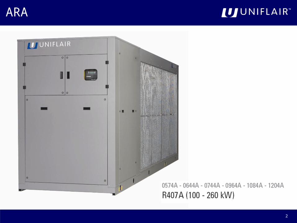
ARA
3
Nominal Cooling Capacities
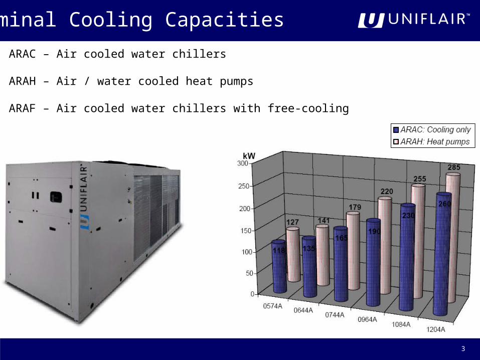
ARAC ndash Air cooled water chillers
ARAH ndash Air water cooled heat pumps
ARAF ndash Air cooled water chillers with free-cooling
4
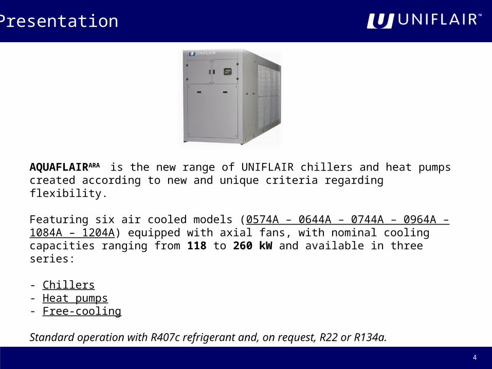
AQUAFLAIRARA is the new range of UNIFLAIR chillers and heat pumps created according to new and unique criteria regarding flexibility
Featuring six air cooled models (0574A ndash 0644A ndash 0744A ndash 0964A ndash 1084A ndash 1204A) equipped with axial fans with nominal cooling capacities ranging from 118 to 260 kW and available in three series
- Chillers- Heat pumps- Free-cooling
Standard operation with R407c refrigerant and on request R22 or R134a
Presentation
5
Simple maintenance and installation of components
Easily accessibleEasily accessibleelectrical panelelectrical panel
Simple replacement of Simple replacement of components (accesscomponents (access from 3 sides)from 3 sides)
Protected userProtected user terminalterminal
Anti-vibration supports to avoid Anti-vibration supports to avoid vibrations inside the unitvibrations inside the unit
Layout ndash Macro Components
6
Layout ndash Macro Components
Shell amp tube evaporatorShell amp tube evaporator
Water tankWater tank Expansion Expansion receiver (24 l - 10 receiver (24 l - 10 bar max)bar max)
Fans Fans
Condensing sectionCondensing section
Electrical panelElectrical panelCirculation pumpCirculation pump
7
Temperature sensor Temperature sensor HH22O inletO inlet
Temperature sensor Temperature sensor HH22O outletO outlet
Differential Differential pressure pressure switchswitch
Second temperature Second temperature sensor Hsensor H22O outletO outlet
Pump shut-off Pump shut-off taptap
Check valveCheck valve
Layout
8
Accessible Accessible dehydration dehydration
filtersfilters
Scroll Scroll CompressorsCompressors
in tandemin tandem
TWIN SYSTEMTWIN SYSTEM
Expansion Expansion valvevalve
Expansion Expansion valvevalve
Layout
9
Main characteristics of the hydraulic sectionMain characteristics of the hydraulic section
bull The check valve is downstream from the pumps this allows easy replacement in the event of pump installation bull 1 or 2 circulation pumps (1+1 in stand by) with automatic control exchange if one of the two is damaged
OptionsOptionsbull 2 possible configurations standard amp high
pressure (150 and 300 kPa)bull Water tank (500 litres and 650 litres) and expansion receiver with safety valve
bullAnti-freeze heaters
bull Algorithm regulation of the inlet water temperature
Layout
10
Cooling system
Twin systemAll of the units are equipped with 4 identically sized compressors placed in parallel in pairs on two refrigerant circuits For this reason the circuits and the compressors are independent from each other
4 STEPS AT ANY GIVEN TIME 4 STEPS AT ANY GIVEN TIME
ELEVATED COP AT PARTIAL LOADSELEVATED COP AT PARTIAL LOADS
OPTIMUM MODULATION OF THE OPTIMUM MODULATION OF THE
COOLING CAPACITYCOOLING CAPACITY
SUPPLIED BY THE UNITSUPPLIED BY THE UNIT
11
All of the models are equipped with four rotary SCROLL compressors connected in tandem
All of the models have two independent refrigerant circuits guaranteeing at least 50 of the cooling capacity in the event of problems with one of the two circuits as well as elevated energy performance at partial loads
bull Electronic protection device on each compressorbull Internal check valve on the compressor dischargebull Rubber anti-vibration supports
OPTIONSOPTIONS
bull Compressor discharge tap bull A cover and other solutions which make the unit Low Noisebull R134a on request
Components ndash the compressor
12
Components ndash refrigerant circuit
bull Composed of two independent refrigerant circuits
bull Expansion valve with internal equalisation
bull Accessible dehydration filters
bull Valve on the liquid line and liquid sight glass with humidity sensor
OPTIONSOPTIONS
bull High and low pressure gauges (onboard)
bull High and low pressure transducers
13
Components ndash fans
bull The units are equipped with axial fans which have a diameter of 800 mm bull There are between 2 and 8 installed on each unit bull They are directly coupled to the electric rotary motor which regulates the speed by means of modulating the power supplybull If it has been requested modulating control of the condensing temperature is available with cut off regulation of the fan speed
This control is standard in low noise and low water temperature versions and when the unit features total or partial heat recovery
14
Components ndash condensing coil
All of the units are designed to work with maximum external temperatures of up to 45degC
bull Each unit features two coils which are placed vertically
bull Copper piping and collection trays and aluminium fins (pitch 18 mm)
OPTIONS OPTIONS
bull Cataphoresis treatment (significant resistance to corrosion thanks to epoxy resin covering)
bull Metallic protection filters for the coils
bull Cu ndash Cu protection
15
Components ndash evaporating coil
Removable Shell amp Tube chilled water exchanger
bull Two gas circuits and a single hydraulic circuit which is able to operate with low head losses
bull The exchanger is completely insulated with closed cell expanded polyurethane to prevent the formation of condensation and to limit thermal dispersion
bull Equipped with anti-freeze sensors
OPTIONS OPTIONS
bull Antindashfreeze heaters around the evaporatorbull Hydraulic connection Kit (standard on units with pumps water tank and ARAF)
16
Components ndash anti-vibration supports
Composed of four springs these supports provide large deflection under load with a small footprint and are therefore particularly effective at insulating at low frequencies
Moreover it is suitable to be used in environments which are particularly difficult and or aggressive since it is highly resistant to oil corrosion and high temperatures
Features
bull the springs are made from elastomer with metallic insertsbull the base is made from metal covered in elastomer (Lexan with stud bolts)
17
Hydronic section
The maximum working pressures areThe maximum working pressures are
bull Basic version (without hydraulic fittings onboard the unit) 10bargbull Basic version equipped with hydraulic connections onboard the unit 6bargbull All of the other versions 5barg
LIST OF MACRO-COMPONENTSLIST OF MACRO-COMPONENTS
1 Pump group 1 or 1+1 with standard or elevated head (optional)2 Water tank (with primary secondary predisposition) (optional)3 Hydraulic tubes Kit hydronic polyurathane fittings onboard the unit (optional for ARAC and ARAH without pump group standard with pump group or water tank and
in the ARAF range)
PlushellipPlushellip
1 Expansion tray and safety valve 2 Water tank3 Double pump shut-off valve4 Bleeding valves on the connections5 Anti-freeze heaters on the evaporator pumps water tank tube fittings
18
Diagram of the hydraulic circuit
Pumps Pumps both standard and high head versions can be selected featuring two pole motors with 2900 rotations per minute
The materials used allow pump operation with pump temperatures between -10degC and 85degC
A Water tank
B Pump shut off tap
C Pump
D Expansion collection tank
E Check valve
F Discharge water temperature sensor
G Evaporator
H Safety valve
I Differential pressure switch
J Second discharge water temperature sensor
K Inlet water temeprature sensor
19
The control
The AQUAFLAIRAQUAFLAIRARAARA range is based on advanced technology which has lead to the use even in the standard version of a new advanced control The control is based on a UPC1mUPC1m card and a mP20IImP20II user interface which is equipped with a large size display Moreover the units are equipped with a LAN card and thanks to a RS485 serial adaptorto a RS485 serial adaptor (optional) are able to be connected to various supervision systems
The control is principally composed of
middot microcompressor control board to which the sensors are connected
middot user interface All of the control algorithms can be found in the microprocessor control and it is also where all of the operating parameters are memorised displayed and set via the user terminal
20
The control
The main functions which are offered by the system are
middot discharge water temperature control based on a settable setpointmiddot possibility of setting a double set-point (in cooling mode)middot possibility of calculating the setpoint depending on the compensation of the external temperaturemiddot complete alarm detection system with visual and acoustic signals indicating the interventions needed to be carried out
middot historical alarm eventsmiddot Alarm signal contacts divided by typemiddot possibility of programming automatic start-up when the power supply returnsmiddot remote start-upshut-down of the unit middot control of all of the compressors operating times pump-down management and compressor rotation in order to guarantee efficiency and reliability
middot 3 types of condensation regolation modulating step and ultra low noise stepmiddot suction pump managementmiddot anti-freeze heater managementmiddot unit management in heat pump modemiddot defrost managementmiddot password on 2 programming levels (setting hardware and software configuration)middot possibility of communicating with a supervision system by means of a communciation protocol Netvisor Modbus Bacnet Lon Metasys SNMP (TCPIP) and Trend
21
middot clockdate management (optional clock card)middot operating hours counter for the main componentsmiddot display of the operating status of all of the unit components and display of the values read by the sensors connected to the control board
middot management of the local network with the possibility of placing a unit in stand-by and setting the operation of this unit in set back mode regulation based on the average temperature and the implementation of step regulation
middot override function with which the operation of the main components can be manually controlled
middot improved control algorithm which continuously measures the external temperature in order to operate more effectively in free-cooling mode
The control
22
Programme identificationLanguage change
It is possible to see the programme version installed in the pCO1 at any timeby using the key This is very important if other units need to be connected to the same
LAN network In fact it is necessary for all the units to have the same software installed
Moreover it is possible to change the language used by pressing the buttons at the same time However the language cannot be changed on the menus concerning hardware and software configuration of the unit that is the service menu
23
To pass from one chiller to another by means of the same user terminal when the units are connected on the same LAN network these buttons must be pressed at the same time
The operating parameters of the unit (temperature humidityhellip) can be seen by pressing
the keys
Return to the status mask by pressing the button
Switch between units in LANDisplay of unit status
24
SET POINT RESET
To carry out a reset of the factory set set-point and other values (except the hardware configurations) press the and buttons at the same time for at least 5 seconds
If the microprocessor board has a clock card installed the date and time will be shown on the status mask
There is also the possibility of setting
bull The start-up and shut-down of the unit according to a time programme
bull Historical alarm event memory
OPTIONAL CLOCK CARD
25
Access to the parameters Consultation amp Programming
READ ONLY allows the parameters to be consulted without the possibility of modifying them
READING amp PROGRAMMING allows the data and parameters which are memorised in the microprocessor board to be modified
1 Press the button until an acoustic signal is heard
2 Immediately press the buttons
3 Insert the password required
MEANING OF THE KEYS Allows the hour-counter to be reset and the hour thresholds to be modified for each component
Allows the second level alarms to be configured
Allows the real configuration of the unit delay setting manual start-up of the units and their components
Contains all the functions linked to the clock card
Allows the set points to be modified
Allows the remote control the LAn and the serial settings to be configured
26
Hardware configuration
The regulation programme of the unit needs to be ldquoconfiguredrdquo that is adapted to the unit in which it is installed it is necessary to define allof the elements featured on the unit and which the microprocessor must control
In general this intervention is required only when the control is installed onboard the unit and this is therefore carried out in the factory during final testing it may however be necessary to reconfigure the unit should further modifications be made to the unit
The passwords are contained inside an envelope along with the documentation which is sent on delivery of the unitFor simple settings the password is 0000 while for hardware configurations it is 0121
27
Hardware configuration
Mask 60 allows
bull Configure the type of unit depending on if the unit is
- a standard chiller- low temperature chiller- chiller with condensing heat recovery- heat pump- heat pump with condensing heat recovery- chiller with free-cooling
bull Selection the number of pumps and modulating regulation of the fan speed
Mask 61 allows the type of refrigerant gas to be set
28
Hardware configuration
Allows the minimum and maximum limits of the set pointto be set
Mask 64 allows the parameters and and condensing temperature intervals to be set by using a remote control switch with a star connection (lowest speed) and a triangle connection (maximum speed)
1048713 TCondPresetTCondPreset when one of the two circuits moves from operation with one compressor running to operation with two compressors running automatic change from star to triangle only occurs if the condensing temp (during star operation) is higher at that value1048713 TCondy SetPTCondy SetP if the condensing temperature exceeds this value when two compressors are operating on one circuit it switches to triangle operation1048713 TCondD SetPTCondD SetP if in triangle operation the condensing temperature falls below this value it returns to star operation
29
The TevPreset TevY SetP and TevD SetP parameters which appear on the following masks have the same means as the previous ones the only difference being that they refer to the evaporating temperatures
Hardware configuration
Star Triangle regulation and viceversa
30
Hardware configuration
Mask 66 allows the frequency of the electric network to be set for fan operation
Mask 67 and the ones following it allow the parameters concerning modulating regulation of the fans to be set depending on the condensing pressure by setting the low noise mode the fan speed regulation is based on three steps rather than two
31
Hardware configuration
Standard modulating regulation
Modulating Regulation in low noise mode
32
In units with free-cooling the mask which is shown here appears which allows the start-up delta T to be set When the external air temperature is lower than the inlet water temperature by the value indicated the unit enters into free-cooling mode the water circulation pump through the free-cooling coil activates and changes the profile of the compressor insertion steps to increase the efficiency of the air-water exchanger
It is also possible to activate free-cooling in the stand ndash by units
Hardware configuration
33
Hardware configuration
Intelligent Free Cooling activated also in the stand ndash by unitsIntelligent Free Cooling activated also in the stand ndash by units
34
Screen 74 gives the option of activating or not the water circulation pump through the free-cooling coil in anti-freeze function If it is activated in the stand-by unit the FC pump is switched on as soon as the external temperature falls below 45degC it switches off when it rises above 55degCNB Only a correct glycol mixture ensures that the coil does not freeze if the external temperature falls below zero the function indicated does not guarantee the integrity of the coil aboveall at extremely low temperatures
Hardware configuration
35
PROGRAMME SETUPPROGRAMME SETUP This function can be useful if there is ldquofoulingrdquo of the data (set-point configuration etc) since it enables the memory to be memory to be cleanedcleaned (including the data concerning the HARDWARE configuration of the unit) all of the set points will automatically all of the set points will automatically be resetbe reset to the values set in the factory (see the DEFAULT VALUESrdquo section)
After this operation has been carried out it is necessary to reconfigure the control and change the set-points if they are required to be different from the default valuesAL PAGE CLEAR-UPAL PAGE CLEAR-UP The cleaning of the historical alarm events cancels all of the alarm events held in the memoryHARDWARE SET-UPHARDWARE SET-UP This enables automatic recognition of the devices connected to the control This operation is useful when options need to be added to the board a sensor needs to be replaced or when the display shows NC instead of a temperature sensor reading
Hardware configuration
36
Remote control of the unit
Start-up and shut-down of the unit can be carried out alternatively by means of1 A remote contact (or ldquoremote control)2 A ldquoSupervision system connected to the microprocessor with a serial cableThe control of the resources with which the unit is equipped is however carried out by the microprocessor
ONOFF BY REMOTE CONTACTONOFF BY REMOTE CONTACT start-up of the unit is carried out by the closure of a remote NO contact when power is connected to the main board (see electrical diagram) In units with a standard regulation programme the digital input 1 is dedicated to the sart-upshut-down of the unit
SUPERVISION SYSTEMSUPERVISION SYSTEM a supervision system exchanges data via a serial cable with the main board of the unit and is controlled remotely for this reason an optional Serial Card is available which opto-couples the interface to a RS485 network to transmit data
37
Mask 141 allows the following to be set
1 The serial address of the unit connected to the serial supervision network
2 The speed of the data transmission 1200 2400 4800 9600 and 19200 per RS485
3 The type of protocol (standard or Modbus)
Remote control of the unit
Moreover on the fourth line the number of units connected in the LAN localnetwork is set (if the unit is predisposed for LAN connection)
38
Units in a local LAN network
bull presence of such management (YesNo) when automatic rotation is activated on a unit with an address lower than the network it is necessary to press the ON button
bull the duration of the automatic cycle between one inversion and the next if it is zero (0) the control will carry out a test placing the units in rotation at intervals of 2 minutesbull the number of units in stand-by
Automatic rotation can happenbull on a timed basis (according to the time of the above mentioned cycle)bull following a second level alarm that is following an alarm for which AR or BR has been set in the alarm address mask
Mask 143 which is only displayed if the local network is configured allows the temperature regulation to be managed in three different waysbull Independent modeIndependent mode the unit control only manages water temperature regulationbull Interconnected modeInterconnected mode the unit control carried out water temperature regulation by calculating the average temperature of the units which are operatingbull Cascade modeCascade mode The control carries out an off-set on the regulation set point depending on the units connected in the network enabling the units therefore to be switched on in succession Each unit maintains its own regulation schedule
39
Mask 144 which is only displayed if the local network is configured allows the unit operation to be managed according to the average temperature reading taken from the ambient of with a local value taken from a single sensor present inside the unit
-Mode Local - Unit control is based on the temperature and humidity readings read by the sensors present on the unit
-Mode Average ndash Unit control is based on the average temperature and humidity reading read by the sensors present on the units connected in the local network
If the difference between the average value and the reading taken by a single sensor is higher than the ldquoAVERAGELOC DIFFldquo value (which by default is 2degC) the control automatically changes from ldquoAVERAGErdquo mode to ldquoLOCALrdquo mode
Units in a local LAN network
40
Operating parameters ndash the setpoint
Mask 120 does not allow settings The discharge water temperature setpoint used as a reference point for regulation is shownA message is shown in the third and fourth line indicating the origin of the setpoint value if it is different that that which is set as standard
-Compensation Text indicates that the setpoint shown in the second line is calculated according to the external temperature (according to the parameters set in the masks shown on the following pages)
-Optional SetPoint indicates that a second setpoint is activated due to the commutation of the contact for digital input 10
-Supervision SetP indicates that the setpoint on the set-back cycle is activated
- Remote Offset Activated indicates that the setpoint is calculated based on the offset read by the analogical input 3 (an option which is possible only if there isnrsquot an evaporator pressure sensor present)
41
This allows the main cooling setpoint to be set and an eventual ldquosecond setpointrdquo activated via commutation of a contact connected to digital input 10
This allows summer compensation of the ccoling setpoint to be set according to the external temperature based on a ramp in which the coordinates of the two angular P1 and P2 points are indicated
Operating parameters ndash the setpoint
42
Operating parameters ndash set back cycle
The set back cycle consists of the automatic start-up of a unit which is switched off ndash but connected to the power supply ndash based on a settable setpoint
Basically the intervention of the set back cycle has the task of controlling the ambient conditions ndash even in a large area ndash andeven when the system is switched off its intervention is therefore not conditioned by the signals issed by a remote controlled system over which it has priority
The intervention of the set back cycle is not considered an alarm condition
43
Reading of the alarms
By pressing the button the alarm buzzer will switch off and the alarm description will be shown on the displayIf the cause of the alarm has been eliminated the last alarm message can be resetBy pressing the button for a few seconds the red light on the button will turn off immediately
If the cause of the alarm has not been eliminated the acoustic signal made by the buzzer will be activated once more
HISTORICAL ALARM SEQUENCEHISTORICAL ALARM SEQUENCE
In order to be able to reconstruct the historical alarm sequence the microprocessor keeps the last 100 alarm events in its memoryAll of the memorized alarm events can be read in series by pressing the button on the STATUS mask
For alarms which are still active general guidelines are shown underneath the description to resolve the problem
44
Reading of the alarms
For a more in-depth description of each alarm please refer to the Control Manual
Thermal pre-alarm of the compressor 1 This automatically re-arms when the contact closes If it is triggered three times in a row within a period of three hours the alarm is activated (NB it is necessary to reset)
45
2
ARA
3
Nominal Cooling Capacities
ARAC ndash Air cooled water chillers
ARAH ndash Air water cooled heat pumps
ARAF ndash Air cooled water chillers with free-cooling
4
AQUAFLAIRARA is the new range of UNIFLAIR chillers and heat pumps created according to new and unique criteria regarding flexibility
Featuring six air cooled models (0574A ndash 0644A ndash 0744A ndash 0964A ndash 1084A ndash 1204A) equipped with axial fans with nominal cooling capacities ranging from 118 to 260 kW and available in three series
- Chillers- Heat pumps- Free-cooling
Standard operation with R407c refrigerant and on request R22 or R134a
Presentation
5
Simple maintenance and installation of components
Easily accessibleEasily accessibleelectrical panelelectrical panel
Simple replacement of Simple replacement of components (accesscomponents (access from 3 sides)from 3 sides)
Protected userProtected user terminalterminal
Anti-vibration supports to avoid Anti-vibration supports to avoid vibrations inside the unitvibrations inside the unit
Layout ndash Macro Components
6
Layout ndash Macro Components
Shell amp tube evaporatorShell amp tube evaporator
Water tankWater tank Expansion Expansion receiver (24 l - 10 receiver (24 l - 10 bar max)bar max)
Fans Fans
Condensing sectionCondensing section
Electrical panelElectrical panelCirculation pumpCirculation pump
7
Temperature sensor Temperature sensor HH22O inletO inlet
Temperature sensor Temperature sensor HH22O outletO outlet
Differential Differential pressure pressure switchswitch
Second temperature Second temperature sensor Hsensor H22O outletO outlet
Pump shut-off Pump shut-off taptap
Check valveCheck valve
Layout
8
Accessible Accessible dehydration dehydration
filtersfilters
Scroll Scroll CompressorsCompressors
in tandemin tandem
TWIN SYSTEMTWIN SYSTEM
Expansion Expansion valvevalve
Expansion Expansion valvevalve
Layout
9
Main characteristics of the hydraulic sectionMain characteristics of the hydraulic section
bull The check valve is downstream from the pumps this allows easy replacement in the event of pump installation bull 1 or 2 circulation pumps (1+1 in stand by) with automatic control exchange if one of the two is damaged
OptionsOptionsbull 2 possible configurations standard amp high
pressure (150 and 300 kPa)bull Water tank (500 litres and 650 litres) and expansion receiver with safety valve
bullAnti-freeze heaters
bull Algorithm regulation of the inlet water temperature
Layout
10
Cooling system
Twin systemAll of the units are equipped with 4 identically sized compressors placed in parallel in pairs on two refrigerant circuits For this reason the circuits and the compressors are independent from each other
4 STEPS AT ANY GIVEN TIME 4 STEPS AT ANY GIVEN TIME
ELEVATED COP AT PARTIAL LOADSELEVATED COP AT PARTIAL LOADS
OPTIMUM MODULATION OF THE OPTIMUM MODULATION OF THE
COOLING CAPACITYCOOLING CAPACITY
SUPPLIED BY THE UNITSUPPLIED BY THE UNIT
11
All of the models are equipped with four rotary SCROLL compressors connected in tandem
All of the models have two independent refrigerant circuits guaranteeing at least 50 of the cooling capacity in the event of problems with one of the two circuits as well as elevated energy performance at partial loads
bull Electronic protection device on each compressorbull Internal check valve on the compressor dischargebull Rubber anti-vibration supports
OPTIONSOPTIONS
bull Compressor discharge tap bull A cover and other solutions which make the unit Low Noisebull R134a on request
Components ndash the compressor
12
Components ndash refrigerant circuit
bull Composed of two independent refrigerant circuits
bull Expansion valve with internal equalisation
bull Accessible dehydration filters
bull Valve on the liquid line and liquid sight glass with humidity sensor
OPTIONSOPTIONS
bull High and low pressure gauges (onboard)
bull High and low pressure transducers
13
Components ndash fans
bull The units are equipped with axial fans which have a diameter of 800 mm bull There are between 2 and 8 installed on each unit bull They are directly coupled to the electric rotary motor which regulates the speed by means of modulating the power supplybull If it has been requested modulating control of the condensing temperature is available with cut off regulation of the fan speed
This control is standard in low noise and low water temperature versions and when the unit features total or partial heat recovery
14
Components ndash condensing coil
All of the units are designed to work with maximum external temperatures of up to 45degC
bull Each unit features two coils which are placed vertically
bull Copper piping and collection trays and aluminium fins (pitch 18 mm)
OPTIONS OPTIONS
bull Cataphoresis treatment (significant resistance to corrosion thanks to epoxy resin covering)
bull Metallic protection filters for the coils
bull Cu ndash Cu protection
15
Components ndash evaporating coil
Removable Shell amp Tube chilled water exchanger
bull Two gas circuits and a single hydraulic circuit which is able to operate with low head losses
bull The exchanger is completely insulated with closed cell expanded polyurethane to prevent the formation of condensation and to limit thermal dispersion
bull Equipped with anti-freeze sensors
OPTIONS OPTIONS
bull Antindashfreeze heaters around the evaporatorbull Hydraulic connection Kit (standard on units with pumps water tank and ARAF)
16
Components ndash anti-vibration supports
Composed of four springs these supports provide large deflection under load with a small footprint and are therefore particularly effective at insulating at low frequencies
Moreover it is suitable to be used in environments which are particularly difficult and or aggressive since it is highly resistant to oil corrosion and high temperatures
Features
bull the springs are made from elastomer with metallic insertsbull the base is made from metal covered in elastomer (Lexan with stud bolts)
17
Hydronic section
The maximum working pressures areThe maximum working pressures are
bull Basic version (without hydraulic fittings onboard the unit) 10bargbull Basic version equipped with hydraulic connections onboard the unit 6bargbull All of the other versions 5barg
LIST OF MACRO-COMPONENTSLIST OF MACRO-COMPONENTS
1 Pump group 1 or 1+1 with standard or elevated head (optional)2 Water tank (with primary secondary predisposition) (optional)3 Hydraulic tubes Kit hydronic polyurathane fittings onboard the unit (optional for ARAC and ARAH without pump group standard with pump group or water tank and
in the ARAF range)
PlushellipPlushellip
1 Expansion tray and safety valve 2 Water tank3 Double pump shut-off valve4 Bleeding valves on the connections5 Anti-freeze heaters on the evaporator pumps water tank tube fittings
18
Diagram of the hydraulic circuit
Pumps Pumps both standard and high head versions can be selected featuring two pole motors with 2900 rotations per minute
The materials used allow pump operation with pump temperatures between -10degC and 85degC
A Water tank
B Pump shut off tap
C Pump
D Expansion collection tank
E Check valve
F Discharge water temperature sensor
G Evaporator
H Safety valve
I Differential pressure switch
J Second discharge water temperature sensor
K Inlet water temeprature sensor
19
The control
The AQUAFLAIRAQUAFLAIRARAARA range is based on advanced technology which has lead to the use even in the standard version of a new advanced control The control is based on a UPC1mUPC1m card and a mP20IImP20II user interface which is equipped with a large size display Moreover the units are equipped with a LAN card and thanks to a RS485 serial adaptorto a RS485 serial adaptor (optional) are able to be connected to various supervision systems
The control is principally composed of
middot microcompressor control board to which the sensors are connected
middot user interface All of the control algorithms can be found in the microprocessor control and it is also where all of the operating parameters are memorised displayed and set via the user terminal
20
The control
The main functions which are offered by the system are
middot discharge water temperature control based on a settable setpointmiddot possibility of setting a double set-point (in cooling mode)middot possibility of calculating the setpoint depending on the compensation of the external temperaturemiddot complete alarm detection system with visual and acoustic signals indicating the interventions needed to be carried out
middot historical alarm eventsmiddot Alarm signal contacts divided by typemiddot possibility of programming automatic start-up when the power supply returnsmiddot remote start-upshut-down of the unit middot control of all of the compressors operating times pump-down management and compressor rotation in order to guarantee efficiency and reliability
middot 3 types of condensation regolation modulating step and ultra low noise stepmiddot suction pump managementmiddot anti-freeze heater managementmiddot unit management in heat pump modemiddot defrost managementmiddot password on 2 programming levels (setting hardware and software configuration)middot possibility of communicating with a supervision system by means of a communciation protocol Netvisor Modbus Bacnet Lon Metasys SNMP (TCPIP) and Trend
21
middot clockdate management (optional clock card)middot operating hours counter for the main componentsmiddot display of the operating status of all of the unit components and display of the values read by the sensors connected to the control board
middot management of the local network with the possibility of placing a unit in stand-by and setting the operation of this unit in set back mode regulation based on the average temperature and the implementation of step regulation
middot override function with which the operation of the main components can be manually controlled
middot improved control algorithm which continuously measures the external temperature in order to operate more effectively in free-cooling mode
The control
22
Programme identificationLanguage change
It is possible to see the programme version installed in the pCO1 at any timeby using the key This is very important if other units need to be connected to the same
LAN network In fact it is necessary for all the units to have the same software installed
Moreover it is possible to change the language used by pressing the buttons at the same time However the language cannot be changed on the menus concerning hardware and software configuration of the unit that is the service menu
23
To pass from one chiller to another by means of the same user terminal when the units are connected on the same LAN network these buttons must be pressed at the same time
The operating parameters of the unit (temperature humidityhellip) can be seen by pressing
the keys
Return to the status mask by pressing the button
Switch between units in LANDisplay of unit status
24
SET POINT RESET
To carry out a reset of the factory set set-point and other values (except the hardware configurations) press the and buttons at the same time for at least 5 seconds
If the microprocessor board has a clock card installed the date and time will be shown on the status mask
There is also the possibility of setting
bull The start-up and shut-down of the unit according to a time programme
bull Historical alarm event memory
OPTIONAL CLOCK CARD
25
Access to the parameters Consultation amp Programming
READ ONLY allows the parameters to be consulted without the possibility of modifying them
READING amp PROGRAMMING allows the data and parameters which are memorised in the microprocessor board to be modified
1 Press the button until an acoustic signal is heard
2 Immediately press the buttons
3 Insert the password required
MEANING OF THE KEYS Allows the hour-counter to be reset and the hour thresholds to be modified for each component
Allows the second level alarms to be configured
Allows the real configuration of the unit delay setting manual start-up of the units and their components
Contains all the functions linked to the clock card
Allows the set points to be modified
Allows the remote control the LAn and the serial settings to be configured
26
Hardware configuration
The regulation programme of the unit needs to be ldquoconfiguredrdquo that is adapted to the unit in which it is installed it is necessary to define allof the elements featured on the unit and which the microprocessor must control
In general this intervention is required only when the control is installed onboard the unit and this is therefore carried out in the factory during final testing it may however be necessary to reconfigure the unit should further modifications be made to the unit
The passwords are contained inside an envelope along with the documentation which is sent on delivery of the unitFor simple settings the password is 0000 while for hardware configurations it is 0121
27
Hardware configuration
Mask 60 allows
bull Configure the type of unit depending on if the unit is
- a standard chiller- low temperature chiller- chiller with condensing heat recovery- heat pump- heat pump with condensing heat recovery- chiller with free-cooling
bull Selection the number of pumps and modulating regulation of the fan speed
Mask 61 allows the type of refrigerant gas to be set
28
Hardware configuration
Allows the minimum and maximum limits of the set pointto be set
Mask 64 allows the parameters and and condensing temperature intervals to be set by using a remote control switch with a star connection (lowest speed) and a triangle connection (maximum speed)
1048713 TCondPresetTCondPreset when one of the two circuits moves from operation with one compressor running to operation with two compressors running automatic change from star to triangle only occurs if the condensing temp (during star operation) is higher at that value1048713 TCondy SetPTCondy SetP if the condensing temperature exceeds this value when two compressors are operating on one circuit it switches to triangle operation1048713 TCondD SetPTCondD SetP if in triangle operation the condensing temperature falls below this value it returns to star operation
29
The TevPreset TevY SetP and TevD SetP parameters which appear on the following masks have the same means as the previous ones the only difference being that they refer to the evaporating temperatures
Hardware configuration
Star Triangle regulation and viceversa
30
Hardware configuration
Mask 66 allows the frequency of the electric network to be set for fan operation
Mask 67 and the ones following it allow the parameters concerning modulating regulation of the fans to be set depending on the condensing pressure by setting the low noise mode the fan speed regulation is based on three steps rather than two
31
Hardware configuration
Standard modulating regulation
Modulating Regulation in low noise mode
32
In units with free-cooling the mask which is shown here appears which allows the start-up delta T to be set When the external air temperature is lower than the inlet water temperature by the value indicated the unit enters into free-cooling mode the water circulation pump through the free-cooling coil activates and changes the profile of the compressor insertion steps to increase the efficiency of the air-water exchanger
It is also possible to activate free-cooling in the stand ndash by units
Hardware configuration
33
Hardware configuration
Intelligent Free Cooling activated also in the stand ndash by unitsIntelligent Free Cooling activated also in the stand ndash by units
34
Screen 74 gives the option of activating or not the water circulation pump through the free-cooling coil in anti-freeze function If it is activated in the stand-by unit the FC pump is switched on as soon as the external temperature falls below 45degC it switches off when it rises above 55degCNB Only a correct glycol mixture ensures that the coil does not freeze if the external temperature falls below zero the function indicated does not guarantee the integrity of the coil aboveall at extremely low temperatures
Hardware configuration
35
PROGRAMME SETUPPROGRAMME SETUP This function can be useful if there is ldquofoulingrdquo of the data (set-point configuration etc) since it enables the memory to be memory to be cleanedcleaned (including the data concerning the HARDWARE configuration of the unit) all of the set points will automatically all of the set points will automatically be resetbe reset to the values set in the factory (see the DEFAULT VALUESrdquo section)
After this operation has been carried out it is necessary to reconfigure the control and change the set-points if they are required to be different from the default valuesAL PAGE CLEAR-UPAL PAGE CLEAR-UP The cleaning of the historical alarm events cancels all of the alarm events held in the memoryHARDWARE SET-UPHARDWARE SET-UP This enables automatic recognition of the devices connected to the control This operation is useful when options need to be added to the board a sensor needs to be replaced or when the display shows NC instead of a temperature sensor reading
Hardware configuration
36
Remote control of the unit
Start-up and shut-down of the unit can be carried out alternatively by means of1 A remote contact (or ldquoremote control)2 A ldquoSupervision system connected to the microprocessor with a serial cableThe control of the resources with which the unit is equipped is however carried out by the microprocessor
ONOFF BY REMOTE CONTACTONOFF BY REMOTE CONTACT start-up of the unit is carried out by the closure of a remote NO contact when power is connected to the main board (see electrical diagram) In units with a standard regulation programme the digital input 1 is dedicated to the sart-upshut-down of the unit
SUPERVISION SYSTEMSUPERVISION SYSTEM a supervision system exchanges data via a serial cable with the main board of the unit and is controlled remotely for this reason an optional Serial Card is available which opto-couples the interface to a RS485 network to transmit data
37
Mask 141 allows the following to be set
1 The serial address of the unit connected to the serial supervision network
2 The speed of the data transmission 1200 2400 4800 9600 and 19200 per RS485
3 The type of protocol (standard or Modbus)
Remote control of the unit
Moreover on the fourth line the number of units connected in the LAN localnetwork is set (if the unit is predisposed for LAN connection)
38
Units in a local LAN network
bull presence of such management (YesNo) when automatic rotation is activated on a unit with an address lower than the network it is necessary to press the ON button
bull the duration of the automatic cycle between one inversion and the next if it is zero (0) the control will carry out a test placing the units in rotation at intervals of 2 minutesbull the number of units in stand-by
Automatic rotation can happenbull on a timed basis (according to the time of the above mentioned cycle)bull following a second level alarm that is following an alarm for which AR or BR has been set in the alarm address mask
Mask 143 which is only displayed if the local network is configured allows the temperature regulation to be managed in three different waysbull Independent modeIndependent mode the unit control only manages water temperature regulationbull Interconnected modeInterconnected mode the unit control carried out water temperature regulation by calculating the average temperature of the units which are operatingbull Cascade modeCascade mode The control carries out an off-set on the regulation set point depending on the units connected in the network enabling the units therefore to be switched on in succession Each unit maintains its own regulation schedule
39
Mask 144 which is only displayed if the local network is configured allows the unit operation to be managed according to the average temperature reading taken from the ambient of with a local value taken from a single sensor present inside the unit
-Mode Local - Unit control is based on the temperature and humidity readings read by the sensors present on the unit
-Mode Average ndash Unit control is based on the average temperature and humidity reading read by the sensors present on the units connected in the local network
If the difference between the average value and the reading taken by a single sensor is higher than the ldquoAVERAGELOC DIFFldquo value (which by default is 2degC) the control automatically changes from ldquoAVERAGErdquo mode to ldquoLOCALrdquo mode
Units in a local LAN network
40
Operating parameters ndash the setpoint
Mask 120 does not allow settings The discharge water temperature setpoint used as a reference point for regulation is shownA message is shown in the third and fourth line indicating the origin of the setpoint value if it is different that that which is set as standard
-Compensation Text indicates that the setpoint shown in the second line is calculated according to the external temperature (according to the parameters set in the masks shown on the following pages)
-Optional SetPoint indicates that a second setpoint is activated due to the commutation of the contact for digital input 10
-Supervision SetP indicates that the setpoint on the set-back cycle is activated
- Remote Offset Activated indicates that the setpoint is calculated based on the offset read by the analogical input 3 (an option which is possible only if there isnrsquot an evaporator pressure sensor present)
41
This allows the main cooling setpoint to be set and an eventual ldquosecond setpointrdquo activated via commutation of a contact connected to digital input 10
This allows summer compensation of the ccoling setpoint to be set according to the external temperature based on a ramp in which the coordinates of the two angular P1 and P2 points are indicated
Operating parameters ndash the setpoint
42
Operating parameters ndash set back cycle
The set back cycle consists of the automatic start-up of a unit which is switched off ndash but connected to the power supply ndash based on a settable setpoint
Basically the intervention of the set back cycle has the task of controlling the ambient conditions ndash even in a large area ndash andeven when the system is switched off its intervention is therefore not conditioned by the signals issed by a remote controlled system over which it has priority
The intervention of the set back cycle is not considered an alarm condition
43
Reading of the alarms
By pressing the button the alarm buzzer will switch off and the alarm description will be shown on the displayIf the cause of the alarm has been eliminated the last alarm message can be resetBy pressing the button for a few seconds the red light on the button will turn off immediately
If the cause of the alarm has not been eliminated the acoustic signal made by the buzzer will be activated once more
HISTORICAL ALARM SEQUENCEHISTORICAL ALARM SEQUENCE
In order to be able to reconstruct the historical alarm sequence the microprocessor keeps the last 100 alarm events in its memoryAll of the memorized alarm events can be read in series by pressing the button on the STATUS mask
For alarms which are still active general guidelines are shown underneath the description to resolve the problem
44
Reading of the alarms
For a more in-depth description of each alarm please refer to the Control Manual
Thermal pre-alarm of the compressor 1 This automatically re-arms when the contact closes If it is triggered three times in a row within a period of three hours the alarm is activated (NB it is necessary to reset)
45
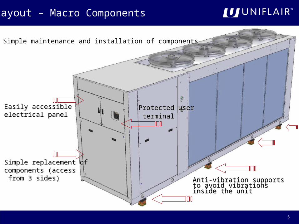
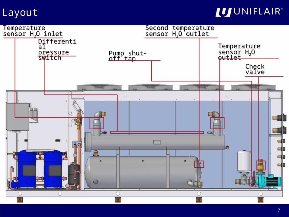
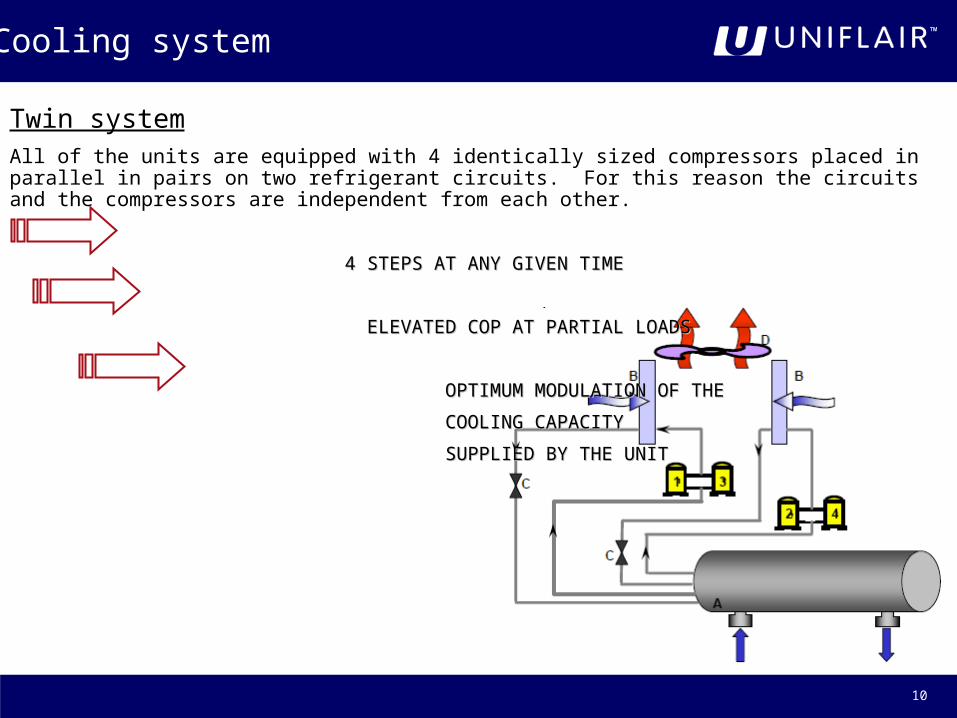
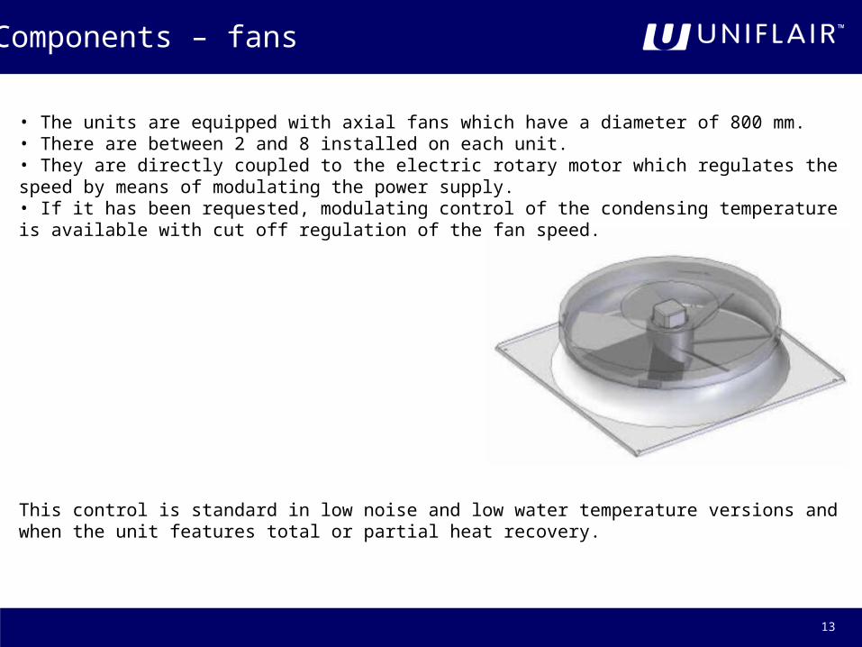
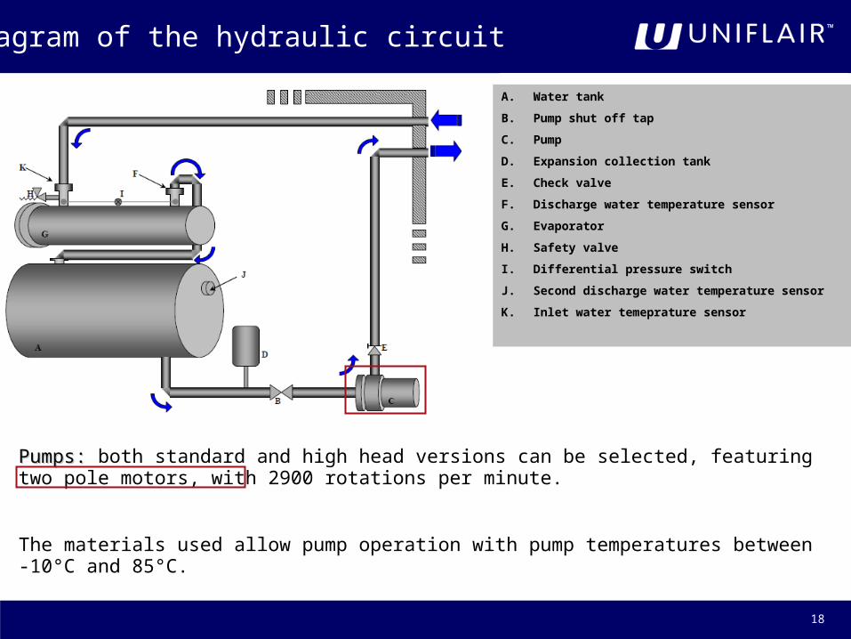
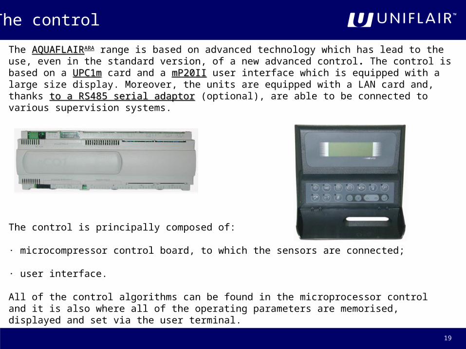
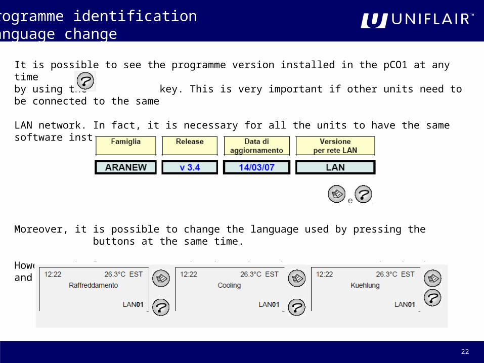
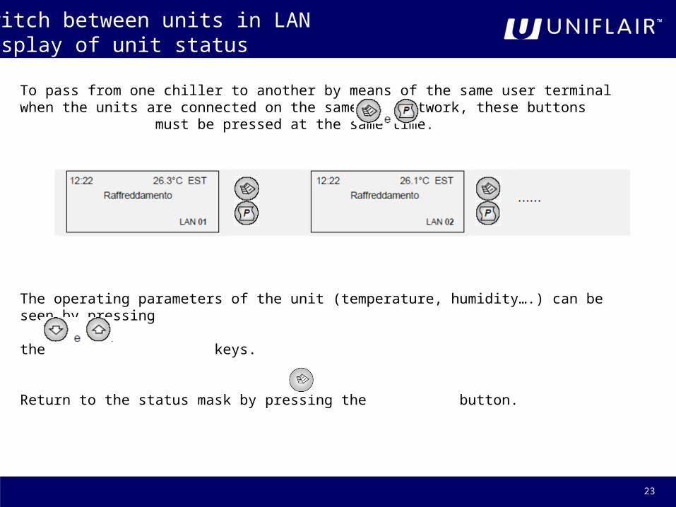
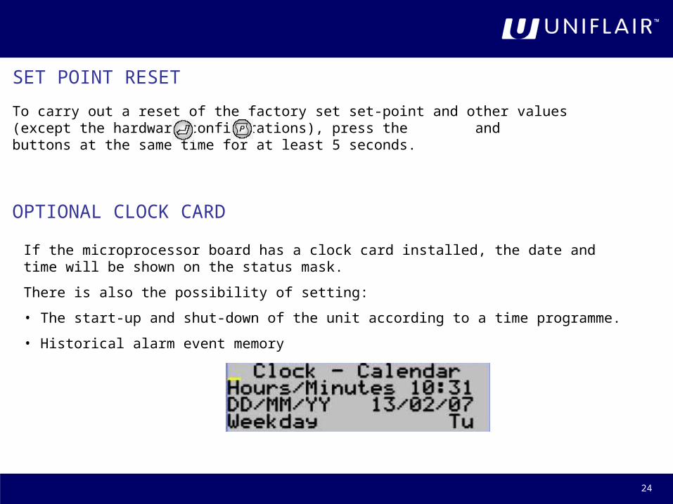
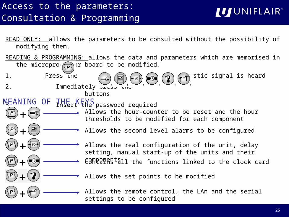
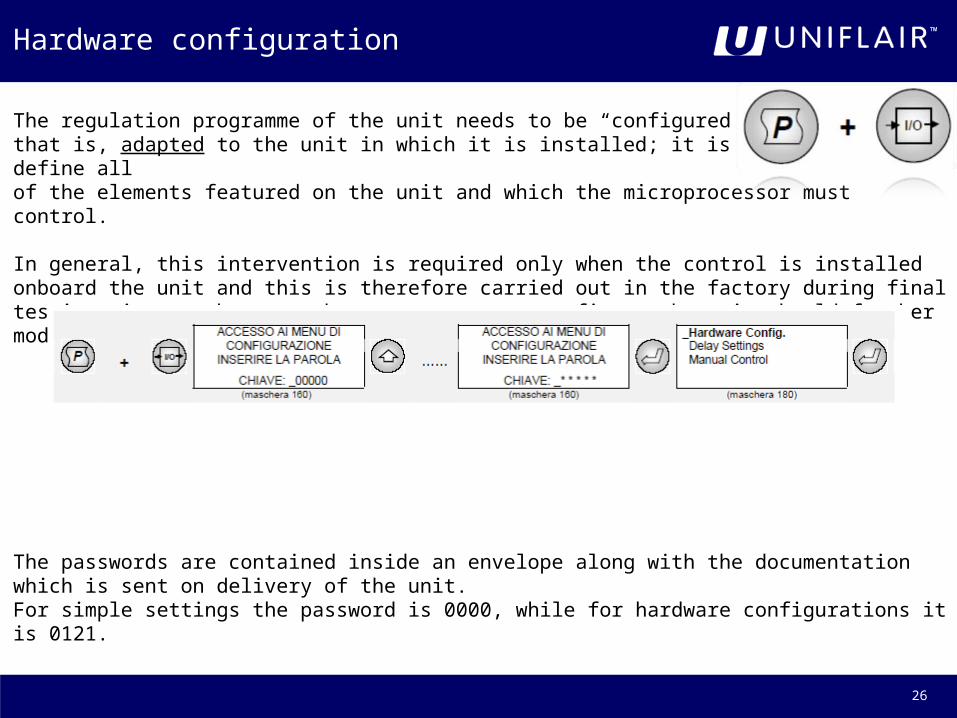
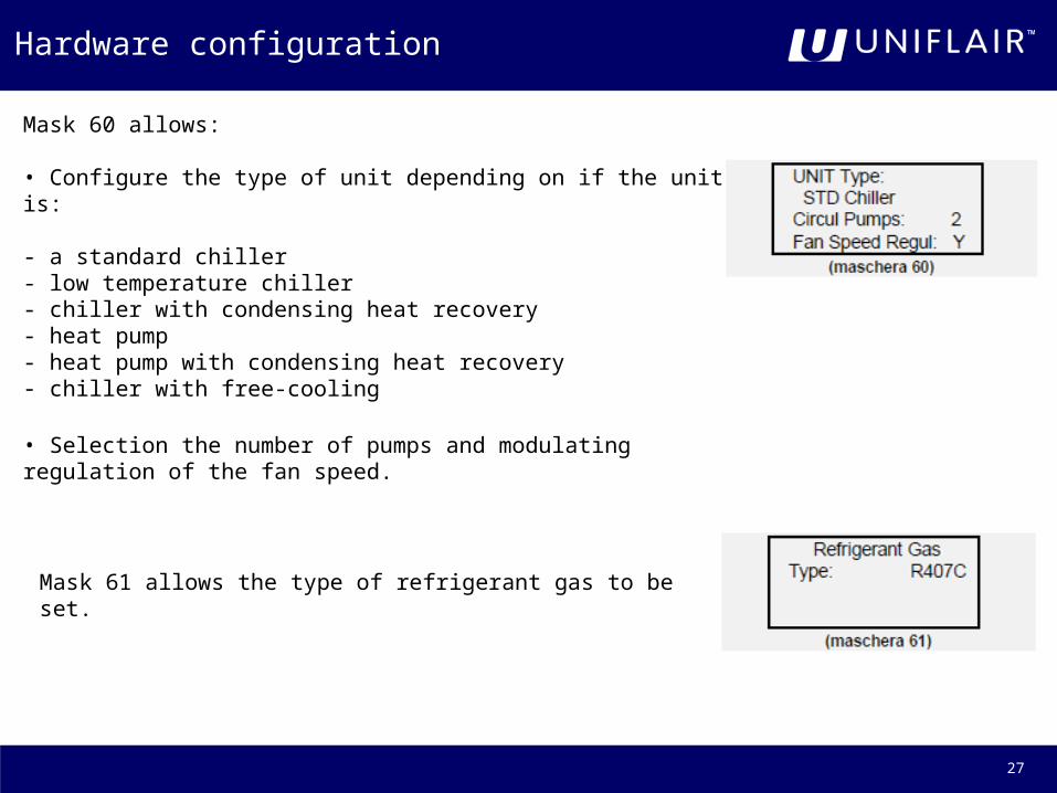
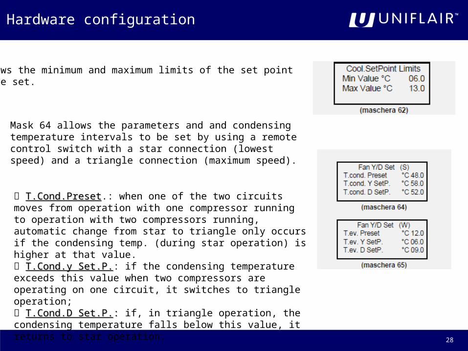
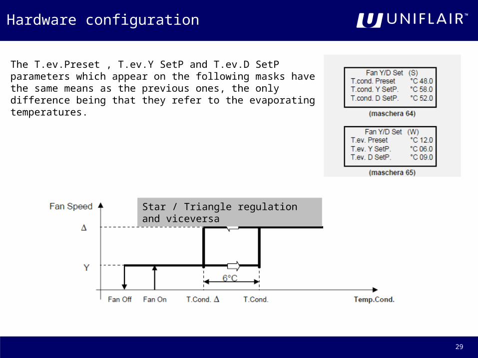
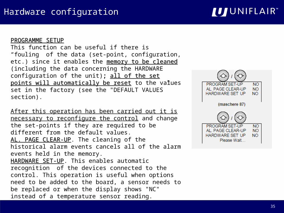
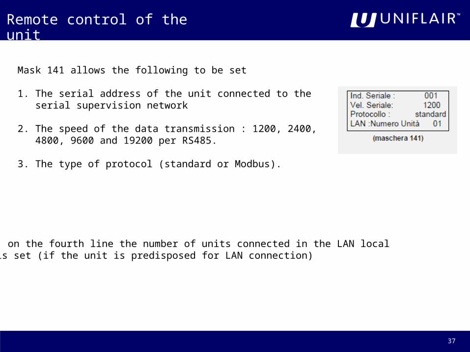
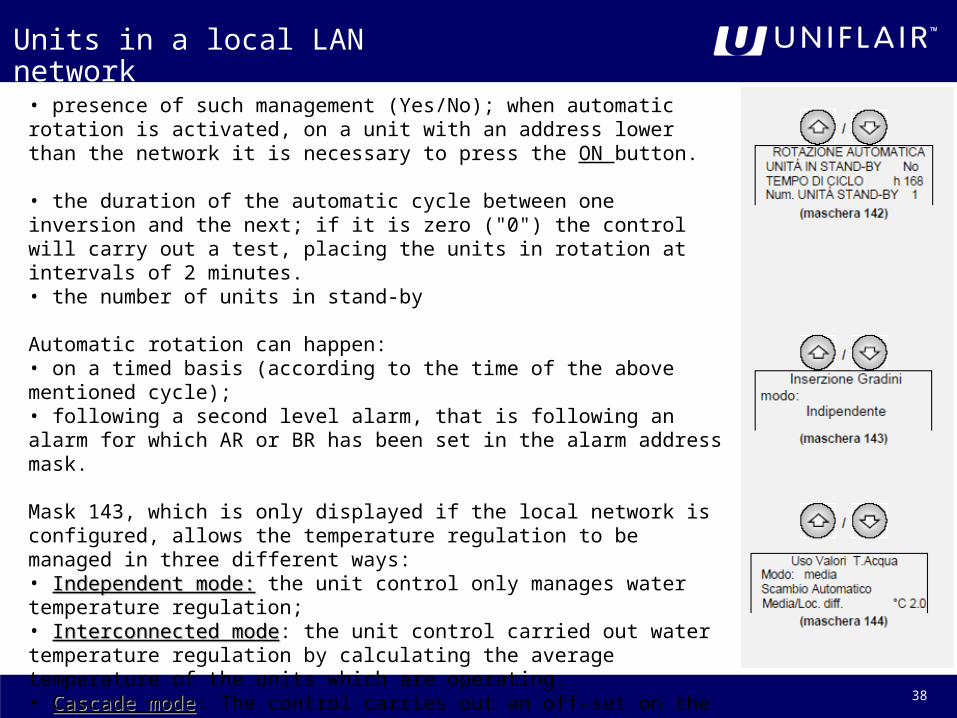
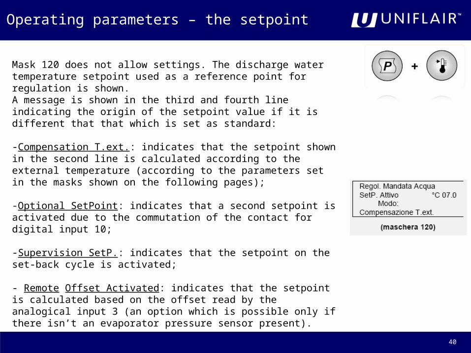
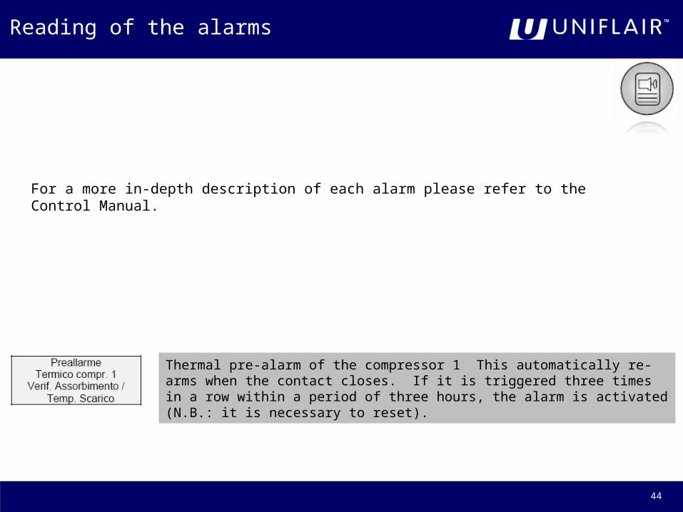

45


