522
115/135/150/175 OptiMax Direct Fuel Injection Starting Model Year 2000 Starting Serial Number OG960500 Starting Model Year 2000 Starting S/N OG960500 115/135/150/175 OptiMax
| Date post: | 23-Oct-2014 |
| Category: |
Documents |
| Upload: | steinstraat |
| View: | 102 times |
| Download: | 5 times |

©2000, Mercury Marine Printed in U.S.A. 90-859494R1 JUNE 2000
115/135/150/175OptiMax
Direct Fuel Injection
Starting Model Year 2000Starting Serial Number OG960500
Starting Model Year 2000
Starting S/N OG960500115/135/150/175 OptiM
ax

90-859494R1 JUNE 2000 Page i
Notice
Throughout this publication, “Dangers”, “Warnings” and “Cautions” (accompanied by the In-ternational HAZARD Symbol ) are used to alert the mechanic to special instructions con-cerning a particular service or operation that may be hazardous if performed incorrectly orcarelessly. OBSERVE THEM CAREFULLY!
These “Safety Alerts” alone cannot eliminate the hazards that they signal. Strict complianceto these special instructions when performing the service, plus “Common Sense” operation,are major accident prevention measures.
DANGERDANGER - Imm ediate hazards which WILL result in severe personal injury or death.
WARNINGWARNING - Hazards or unsafe practices which COULD result in severe personal in-jury or death.
CAUTIONHazards or unsafe practices which could result in minor personal injury or productor property damage.
Notice to Users of This Manual
This service manual has been written and published by the Service Department of MercuryMarine to aid our dealers’ mechanics and company service personnel when servicing theproducts described herein.
It is assumed that these personnel are familiar with the servicing procedures of these prod-ucts, or like or similar products manufactured and marketed by Mercury Marine, that theyhave been trained in the recommended servicing procedures of these products which in-cludes the use of mechanics’ common hand tools and the special Mercury Marine or recom-mended tools from other suppliers.
We could not possibly know of and advise the service trade of all conceivable proceduresby which a service might be performed and of the possible hazards and/or results of eachmethod. We have not undertaken any such wide evaluation. Therefore, anyone who usesa service procedure and/or tool, which is not recommended by the manufacturer, first mustcompletely satisfy himself that neither his nor the products safety will be endangered by theservice procedure selected.
All information, illustrations and specifications contained in this manual are based on thelatest product information available at the time of publication. As required, revisions to thismanual will be sent to all dealers contracted by us to sell and/or service these products.
It should be kept in mind, while working on the product, that the electrical system and ignitionsystem are capable of violent and damaging short circuits or severe electrical shocks. Whenperforming any work where electrical terminals could possibly be grounded or touched bythe mechanic, the battery cables should be disconnected at the battery.
Any time the intake or exhaust openings are exposed during service they should be coveredto protect against accidental entrance of foreign material which could enter the cylinders andcause extensive internal damage when the engine is started.
Page ii 90-859494R1 JUNE 2000
It is important to note, during any maintenance procedure replacement fasteners must havethe same measurements and strength as those removed. Numbers on the heads of the met-ric bolts and on the surfaces of metric nuts indicate their strength. American bolts use radiallines for this purpose, while most American nuts do not have strength markings. Mis-matched or incorrect fasteners can result in damage or malfunction, or possibly personalinjury. Therefore, fasteners removed should be saved for reuse in the same locations when-ever possible. Where the fasteners are not satisfactory for re-use, care should be taken toselect a replacement that matches the original.
Cleanliness and Care of Outboard Motor
A marine power product is a combination of many machined, honed, polished and lappedsurfaces with tolerances that are measured in the ten thousands of an inch/mm. When anyproduct component is serviced, care and cleanliness are important. Throughout this manu-al, it should be understood that proper cleaning, and protection of machined surfaces andfriction areas is a part of the repair procedure. This is considered standard shop practiceeven if not specifically stated.
Whenever components are removed for service, they should be retained in order. At thetime of installation, they should be installed in the same locations and with the same matingsurfaces as when removed.
Personnel should not work on or under an outboard which is suspended. Outboards shouldbe attached to work stands, or lowered to ground as soon as possible.
We reserve the right to make changes to this manual without prior notification.
Refer to dealer service bulletins for other pertinent information concerning the products de-scribed in this manual.
Page Numbering
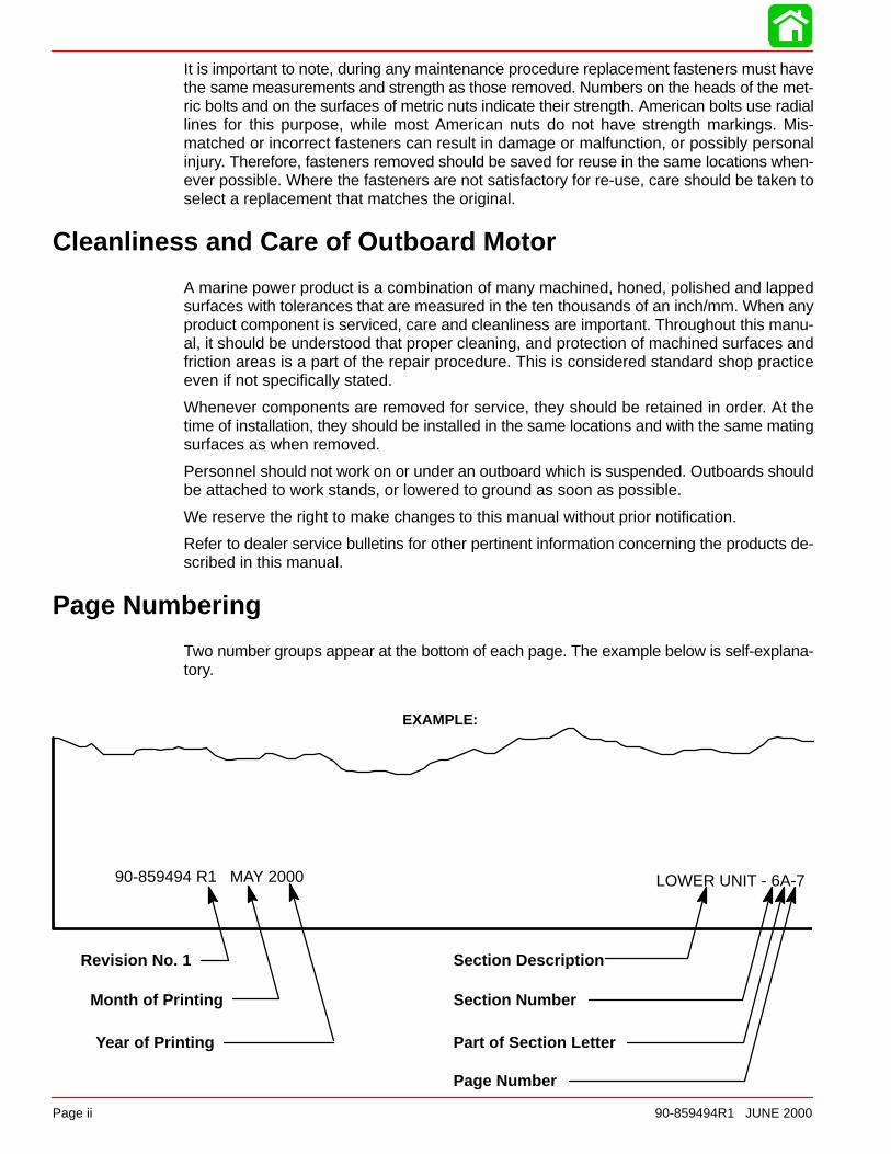
Two number groups appear at the bottom of each page. The example below is self-explana-tory.
EXAMPLE:
90-859494 R1 MAY 2000 LOWER UNIT - 6A-7
Revision No. 1
Month of Printing
Year of Printing
Section Description
Section Number
Part of Section Letter
Page Number

1
2
3
4
5
6
7
General Information& Specifications
Ignition System
Fuel System
Powerhead
Mid-Section
Gear Housing
Attachment/Control Linkage
8Color Diagrams
90-859494R1 JUNE 2000 Page iii
Service Manual Outline
Section 1 - General Information & SpecificationsA - SpecificationsB - MaintenanceC - General InformationD - Outboard Installation
Section 2 - ElectricalA - IgnitionB - Charging & Starting SystemC - Timing, Synchronizing & AdjustingD - Wiring Diagrams
Section 3 - Fuel SystemA - Fuel PumpB - Direct Fuel InjectionC - Oil InjectionD - Emissions
Section 4 - PowerheadA - PowerheadB - Cooling
Section 5 - Mid-SectionA - Clamp/Swivel Brackets & Drive Shaft HousingB - Power Trim – Design I (Showa)C - Power Trim – Design II (Oildyne)
Section 6 - Gear HousingA - Right Hand (Standard) Rotation Non-RatchetingB - Left Hand (Counter) Rotattion Non-Ratcheting
Section 7 - Attachments/Control LinkageSection 8 - Color Diagrams
1A
SPECIFICATIONS
90-855347R1 JANUARY 1999 Page 1A-1
IMPORTANT INFORMATIONSection 1A - Specifications
Table of Contents
Master Specifications 1A-1. . . . . . . . . . . . . . . . . . . . . . . . .
Master Specifications
Model 135/150 DFIHORSEPOWER
(KW)Model 135Model 150
Full Throttle RPM (135/150)Idle RPM (In Gear) (135/150)
RPM Limiter1998 Model 135/1501999 Model 1351999 Model 150
135 (100.7 kw)150 (111.8 kw)
5000 - 5600550 ± 25
575057505950
OUTBOARDWEIGHT
Model 135/150– 20 in. (50.8cm) Shaft– 25 in. (63.5cm) Shaft
440.0 lbs. (200.0 kg)452.0 lbs. (206.0 kg)
CYLINDERBLOCK
TypeDisplacement
V-6 Cylinder, Two Cycle, Direct Injected153 cu. in. (2508 cc) 60° Vee
STROKE Length (All Models) 2.65 in. (67.3 mm)
CYLINDERBORE
Diameter (Std)Diameter 0.015 in. OversizeTaper/Out of Round/Wear MaximumBore Type
3.501 in. (88.925 mm)3.516 in. (89.306 mm)0.003 in. (0.076 mm)
Cast Iron
CRANKSHAFT Maximum Runout 0.006 in. (0.152 mm)
PISTON Piston TypeDiameter Standard
Diameter 0.015 in. Oversize
Aluminum3.4925 in. ± .0005 in. (88.7095 mm ±
0.0127 mm)3.5075 in. ± 0.0005 in.
(89.0905 mm ± 0.0127 mm)
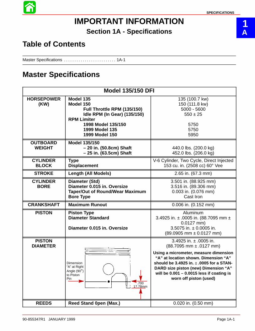
PISTONDIAMETER
Dimension“A” at RightAngle (90°)to PistonPin
.70017.78mm
3.4925 in. ± .0005 in.(88.7095 mm ± .0127 mm)
Using a micrometer, measure dimension“A” at location shown. Dimension “A”
should be 3.4925 in. ± .0005 for a STAN-DARD size piston (new) Dimension “A”will be 0.001 – 0.0015 less if coating is
worn off piston (used)
REEDS Reed Stand 0pen (Max.) 0.020 in. (0.50 mm)

SPECIFICATIONS
Page 1A-2 90-855347R1 JANUARY 1999
Model 135/150 DFI
MIDSECTION
Power Trim (Total Tilt Range)Power Trim (Tilt Range)Steering Pivot RangeTilt Pin Adjustment PositionsAllowable Transom Thickness
73°19°60°4
2-3/8 in. (6.03 cm)
GEARHOUSING
Gear RatioStandard Ratio – 135Standard Ratio – 150Optional High Altitude Ratio
– 135 – 150
Gearcase Capacity
Pinion Height
Forward Gear Backlash– 1.87:1
– 2.00:1
– 2.30:1
Reverse Gear Backlash– Standard/Counter Rotation
Water Pressure @ RPM
2.00:1 12/24 Teeth1.87:1 15/28 Teeth
2.30:1 13/30 Teeth2.00:1 12/24 Teeth
22.5 fl. oz. (665.4 ml)
0.025 in. (0.635 mm).
0.017 in. – 0.028 in. (0.431 mm – 0.711 mm)
0.015 in. – 0.022 in. (0.381 mm – 0.558 mm)
0.018 in. – 0.023 in. (0.460 mm – 0.584 mm)
0.030 in. to 0.050 in. (0.076 mm to 0.127 mm)
12 PSI Minimum @ 5500 RPM
DIRECTINJECTION
Injectors– Quantity– Injectors are Crank Angle Drivenby ECM
– #2 Cylinder– #4 Cylinder– #6 Cylinder– #1 Cylinder– #3 Cylinder– #5 Cylinder
Fuel Line Pressure @ InjectorsAir PressureHigh Pressure Electric Fuel PumpAmperage DrawLow Pressure Electric Fuel PumpAmperage DrawLow Pressure Electric Fuel PumpOutputFuel Injector Ohm ResistanceDirect Injector Ohm ResistanceFuel/Air Differential
6
WHT/RED + RED/WHT LeadsWHT/YEL + YEL/WHT LeadsWHT/PPL + PPL/WHT LeadsWHT/BRN + BRN/WHT LeadsWHT/ORG + ORG/WHT Leads
WHT/DRK BLU + DRK BLU/WHTLeads
89 ± 2 psi (613.5 ± 13.8 kPa)79 ± 2 psi (544.0 ± 13.8 kPa)
5 – 9 Amperes
1 – 2 Amperes
6 – 9 psi (41.37 – 62.04 kPa)1.8 ± 0.1 Ω1.3 ± 0.3 Ω
10 psi (68.5 kPa)
SPECIFICATIONS
90-855347R1 JANUARY 1999 Page 1A-3
Master SpecificationsModel 135/150 DFI
FUELSYSTEM
FuelRecommended GasolineRecommended Oil
Gasoline/Oil Ratio – @ Idle
– @ WOTFuel Pressure
Crankcase Pump – @ Idle– @ WOT
Gasoline w/Oil InjectionUnleaded 87 Octane Minimum
Quicksilver TC-W3 Premium Plus 2Cycle Outboard Oil
300 – 400:160:1
2 psi (13.8 kPa)8 psi (55.2 kPa)
STARTINGSYSTEM
Electric Start – All ModelsStarter Draw (Under Load)Starter Draw (No Load)Minimum Brush Length
Battery Rating
165 Amperes30 Amperes
0.25 in. (65.4 mm)
1000 (Minimum) Marine Cranking Amps(MCA)
750 (Minimum) Cold Cranking Amps(CCA)
IGNITIONSYSTEM
TypeSpark Plug Type
Spark Plug GapMaximum TimingIdle TimingThrottle Position Sensor 1 (InnerTPS)
@ Idle@ W.O.T
Throttle Position Sensor 2 (OuterTPS)
@ Idle@ W.O.T
Crank Position SensorAir Gap
Digital InductiveNGK PZFR5F-11NGK ZFR5F-11 or
Champion RC12MC4 0.040 in. (1.0 mm)
Not Adjustable; Controlled by ECMNot Adjustable; Controlled by ECM
3.70 – 4.90 VDC0.30 – 1.80 VDC
0.10 – 1.50 VDC3.20 – 4.90 VDC
0.025 in. – 0.040 in. (0.635 mm – 1.01 mm)
CHARGINGSYSTEM
Alternator Output (Regulated)
Brush Length
Voltage OutputRegulator Current Draw
32 - 38 Amperes @ 2000 RPM@ Battery*
52 - 60 Amperes @ 2000 RPM@ Alternator
Std Exposed Length:0.413 in. (10.5 mm)
Min. Exposed Length:0.059 in. (1.5 mm)13.5 to 15.1 Volts
0.15 mA (Ign. Switch Off)30.0 mA (Ign. Switch On)
*Amperage listed is when battery is in a discharged state. If battery is fully charged, amperage readings willbe less.

1B
MAINTENANCE
90-855347R1 JANUARY 1999 Page 1B-1
IMPORTANT INFORMATIONSection 1B - Maintenance
Table of Contents
Specifications 1B-1. . . . . . . . . . . . . . . . . . . . . . . . . . . . . . . . Gear Case Lubricant Capacity 1B-1. . . . . . . . . . . . . .
Special Tools 1B-2. . . . . . . . . . . . . . . . . . . . . . . . . . . . . . . . Quicksilver Lubricant/Sealant 1B-2. . . . . . . . . . . . . . . . . . Inspection and Maintenance Schedule 1B-4. . . . . . . . . .
Before Each Use 1B-4. . . . . . . . . . . . . . . . . . . . . . . . . . After Each Use 1B-4. . . . . . . . . . . . . . . . . . . . . . . . . . . . Every 100 Hours of Use or Once yearly,Whichever occurs first 1B-4. . . . . . . . . . . . . . . . . . . . .
Flushing Engine 1B-5. . . . . . . . . . . . . . . . . . . . . . . . . . . . . . Flushing Cooling System – Using CowlFlush Plug 1B-5. . . . . . . . . . . . . . . . . . . . . . . . . . . . . . . . Flushing Cooling System – Using FlushingAttachment 44357A2 1B-5. . . . . . . . . . . . . . . . . . . . . .
Fuel System 1B-6. . . . . . . . . . . . . . . . . . . . . . . . . . . . . . . . . Fuel Line Inspection 1B-6. . . . . . . . . . . . . . . . . . . . . . . Water Separating Fuel Filter 1B-6. . . . . . . . . . . . . . . .
Corrosion Control Anode 1B-7. . . . . . . . . . . . . . . . . . . . . . Spark Plug Inspection 1B-7. . . . . . . . . . . . . . . . . . . . . . . . . Battery Inspection 1B-8. . . . . . . . . . . . . . . . . . . . . . . . . . . . Fuse Replacement 1B-8. . . . . . . . . . . . . . . . . . . . . . . . . . . Compressor Air intake Filter 1B-9. . . . . . . . . . . . . . . . . . .
Removal 1B-9. . . . . . . . . . . . . . . . . . . . . . . . . . . . . . . . . Installation 1B-9. . . . . . . . . . . . . . . . . . . . . . . . . . . . . . . .
Lubrication Points 1B-9. . . . . . . . . . . . . . . . . . . . . . . . . . . . Checking Power Trim Fluid 1B-11. . . . . . . . . . . . . . . . . . . Gear Case Lubrication 1B-12. . . . . . . . . . . . . . . . . . . . . . . Storage Preparation 1B-13. . . . . . . . . . . . . . . . . . . . . . . . .
Specifications
Gear Case Lubricant Capacity
Gear Case Ratio Capacity1.87:1 22.5 fl. oz. (665ml)
2.00:1 22.5 fl. oz. (665ml)
2.30:1 22.5 fl. oz. (665ml)
MAINTENANCE
Page 1B-2 90-855347R1 JANUARY 1999
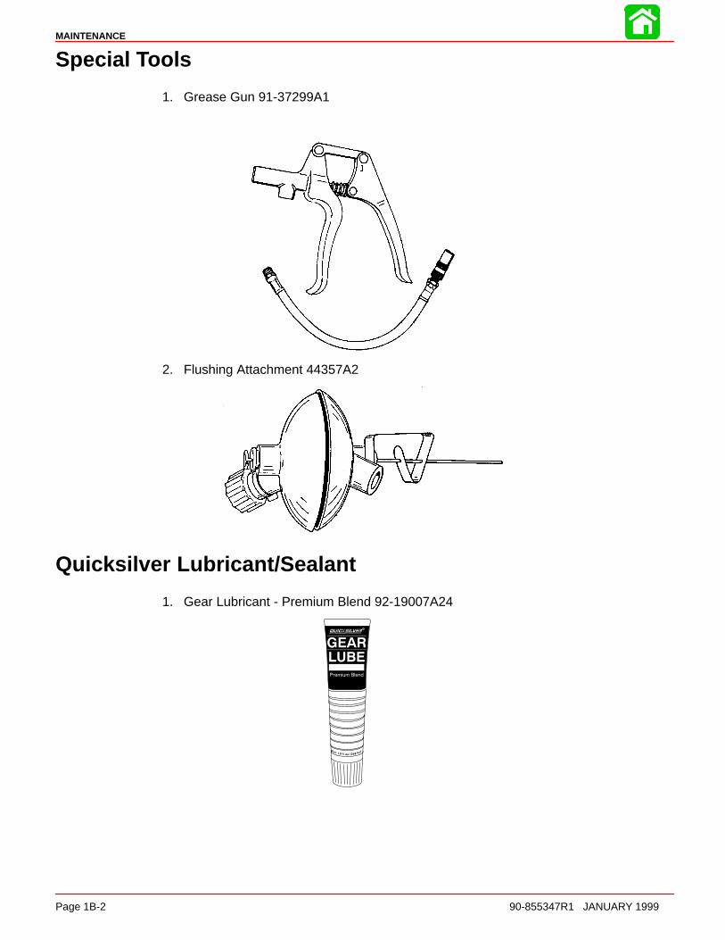
Special Tools
1. Grease Gun 91-37299A1
2. Flushing Attachment 44357A2
Quicksilver Lubricant/Sealant
1. Gear Lubricant - Premium Blend 92-19007A24

MAINTENANCE
90-855347R1 JANUARY 1999 Page 1B-3
2. Anti-Corrosion Grease 92-78376A6
3. 2-4-C Marine Lubricant with Teflon 92-825407A12
4. SAE 30W Motor Oil (Obtain Locally)
5. Quicksilver Power Trim and Steering Fluid 91-90100A12)
MAINTENANCE
Page 1B-4 90-855347R1 JANUARY 1999
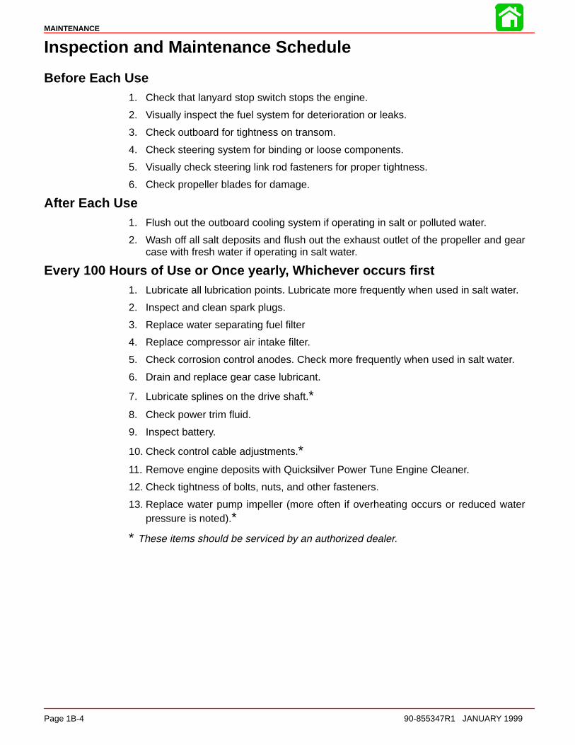
Inspection and Maintenance Schedule
Before Each Use1. Check that lanyard stop switch stops the engine.
2. Visually inspect the fuel system for deterioration or leaks.
3. Check outboard for tightness on transom.
4. Check steering system for binding or loose components.
5. Visually check steering link rod fasteners for proper tightness.
6. Check propeller blades for damage.
After Each Use1. Flush out the outboard cooling system if operating in salt or polluted water.
2. Wash off all salt deposits and flush out the exhaust outlet of the propeller and gearcase with fresh water if operating in salt water.
Every 100 Hours of Use or Once yearly, Whichever occurs first1. Lubricate all lubrication points. Lubricate more frequently when used in salt water.
2. Inspect and clean spark plugs.
3. Replace water separating fuel filter
4. Replace compressor air intake filter.
5. Check corrosion control anodes. Check more frequently when used in salt water.
6. Drain and replace gear case lubricant.
7. Lubricate splines on the drive shaft.∗8. Check power trim fluid.
9. Inspect battery.
10. Check control cable adjustments.∗11. Remove engine deposits with Quicksilver Power Tune Engine Cleaner.
12. Check tightness of bolts, nuts, and other fasteners.
13. Replace water pump impeller (more often if overheating occurs or reduced waterpressure is noted).∗
∗ These items should be serviced by an authorized dealer.
MAINTENANCE
90-855347R1 JANUARY 1999 Page 1B-5
Flushing Engine
Flushing Cooling System – Using Cowl Flush PlugFlush the internal water passages of the outboard with fresh water after each use in salt,polluted or muddy water. This will help prevent a buildup of deposits from clogging theinternal water passages.
NOTE: Engine can be stopped or running at idle speed when flushing the cooling system.Do not flush engine using a water system that exceeds 45 psi.
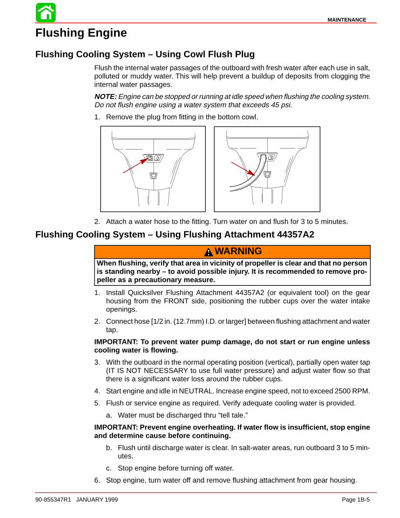
1. Remove the plug from fitting in the bottom cowl.
2. Attach a water hose to the fitting. Turn water on and flush for 3 to 5 minutes.
Flushing Cooling System – Using Flushing Attachment 44357A2
WARNINGWhen flushing, verify that area in vicinity of propeller is clear and that no personis standing nearby – to avoid possible injury. It is recommended to remove pro-peller as a precautionary measure.
1. Install Quicksilver Flushing Attachment 44357A2 (or equivalent tool) on the gearhousing from the FRONT side, positioning the rubber cups over the water intakeopenings.
2. Connect hose [1/2 in. (12.7mm) I.D. or larger] between flushing attachment and watertap.
IMPORTANT: To prevent water pump damage, do not start or run engine unlesscooling water is flowing.
3. With the outboard in the normal operating position (vertical), partially open water tap(IT IS NOT NECESSARY to use full water pressure) and adjust water flow so thatthere is a significant water loss around the rubber cups.
4. Start engine and idle in NEUTRAL. Increase engine speed, not to exceed 2500 RPM.
5. Flush or service engine as required. Verify adequate cooling water is provided.
a. Water must be discharged thru “tell tale.”
IMPORTANT: Prevent engine overheating. If water flow is insufficient, stop engineand determine cause before continuing.
b. Flush until discharge water is clear. In salt-water areas, run outboard 3 to 5 min-utes.
c. Stop engine before turning off water.
6. Stop engine, turn water off and remove flushing attachment from gear housing.
MAINTENANCE
Page 1B-6 90-855347R1 JANUARY 1999
IMPORTANT: While and after flushing, keep outboard in upright position until allwater has drained from drive shaft housing to prevent water from entering the pow-erhead via drive shaft housing and exhaust ports.
Fuel System
WARNINGAvoid serious injury or death from gasoline fire or explosion. Carefully follow allfuel system service instructions. Always stop the engine and DO NOT smoke orallow open flames or sparks in the area while servicing any part of the fuel sys-tem.
Before servicing any part of the fuel system, stop engine and disconnect the battery. Drainthe fuel system completely. Use an approved container to collect and store fuel. Wipe upany spillage immediately. Material used to contain spillage must be disposed of in an ap-proved receptacle. Any fuel system service must be performed in a well ventilated area.Inspect any completed service work for sign of fuel leakage.
Fuel Line InspectionVisually inspect the fuel line and primer bulb for cracks, swelling, leaks, hardness, or othersigns of deterioration or damage. If any of these conditions is found, the fuel line or primerbulb must be replaced.
Water Separating Fuel FilterNOTE: The warning system will turn on when water in the fuel filter reaches the full level.
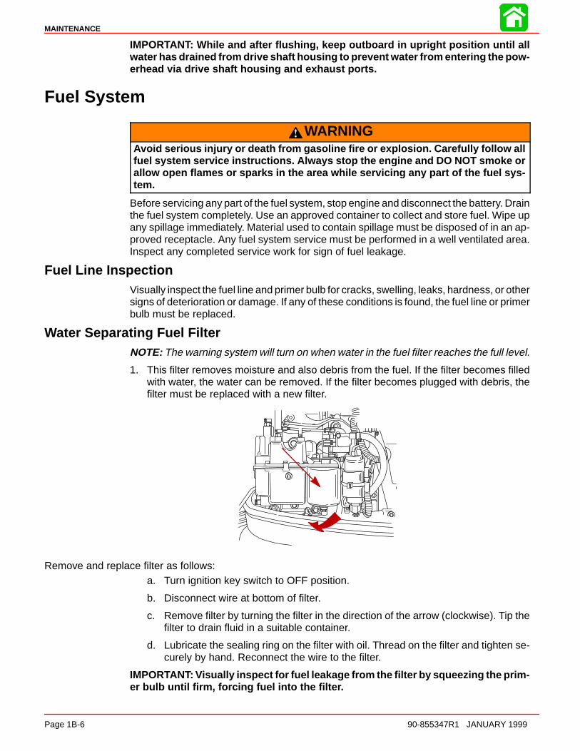
1. This filter removes moisture and also debris from the fuel. If the filter becomes filledwith water, the water can be removed. If the filter becomes plugged with debris, thefilter must be replaced with a new filter.
Remove and replace filter as follows:a. Turn ignition key switch to OFF position.
b. Disconnect wire at bottom of filter.
c. Remove filter by turning the filter in the direction of the arrow (clockwise). Tip thefilter to drain fluid in a suitable container.
d. Lubricate the sealing ring on the filter with oil. Thread on the filter and tighten se-curely by hand. Reconnect the wire to the filter.
IMPORTANT: Visually inspect for fuel leakage from the filter by squeezing the prim-er bulb until firm, forcing fuel into the filter.
MAINTENANCE
90-855347R1 JANUARY 1999 Page 1B-7
Corrosion Control Anode
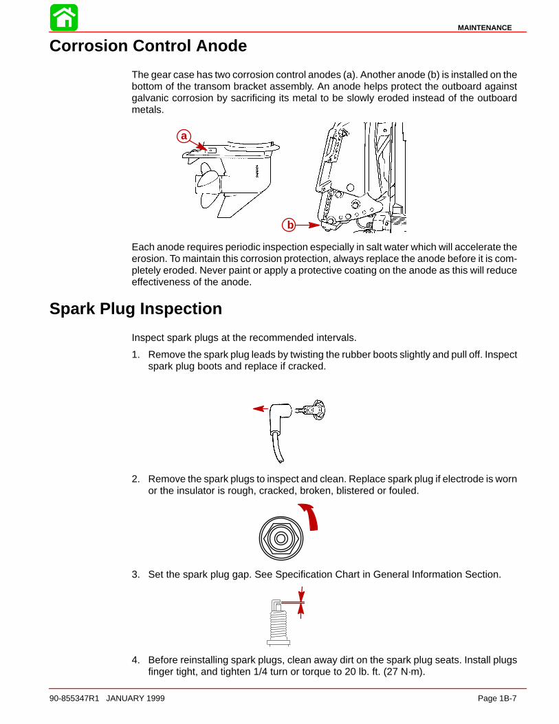
The gear case has two corrosion control anodes (a). Another anode (b) is installed on thebottom of the transom bracket assembly. An anode helps protect the outboard againstgalvanic corrosion by sacrificing its metal to be slowly eroded instead of the outboardmetals.
a
b
Each anode requires periodic inspection especially in salt water which will accelerate theerosion. To maintain this corrosion protection, always replace the anode before it is com-pletely eroded. Never paint or apply a protective coating on the anode as this will reduceeffectiveness of the anode.
Spark Plug Inspection
Inspect spark plugs at the recommended intervals.
1. Remove the spark plug leads by twisting the rubber boots slightly and pull off. Inspectspark plug boots and replace if cracked.
2. Remove the spark plugs to inspect and clean. Replace spark plug if electrode is wornor the insulator is rough, cracked, broken, blistered or fouled.
3. Set the spark plug gap. See Specification Chart in General Information Section.
4. Before reinstalling spark plugs, clean away dirt on the spark plug seats. Install plugsfinger tight, and tighten 1/4 turn or torque to 20 lb. ft. (27 N·m).
MAINTENANCE
Page 1B-8 90-855347R1 JANUARY 1999
Battery Inspection
The battery should be inspected at periodic intervals to ensure proper engine startingcapability.
IMPORTANT: Read the safety and maintenance instructions which accompanyyour battery.
1. Turn off the engine before servicing the battery.
2. Add water as necessary to keep the battery full.
3. Make sure the battery is secure against movement.
4. Battery cable terminals should be clean, tight, and correctly installed. Positive to posi-tive and negative to negative.
5. Make sure the battery is equipped with a nonconductive shield to prevent accidentalshorting of battery terminals.
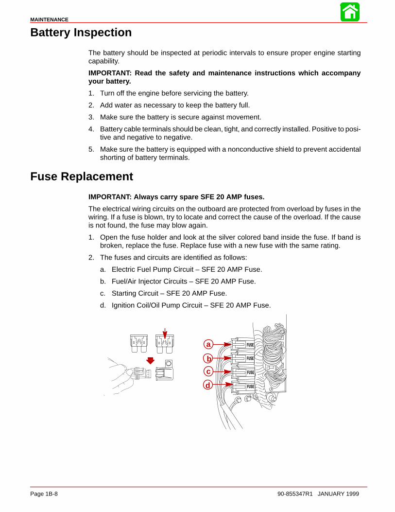
Fuse Replacement
IMPORTANT: Always carry spare SFE 20 AMP fuses.
The electrical wiring circuits on the outboard are protected from overload by fuses in thewiring. If a fuse is blown, try to locate and correct the cause of the overload. If the causeis not found, the fuse may blow again.
1. Open the fuse holder and look at the silver colored band inside the fuse. If band isbroken, replace the fuse. Replace fuse with a new fuse with the same rating.
2. The fuses and circuits are identified as follows:
a. Electric Fuel Pump Circuit – SFE 20 AMP Fuse.
b. Fuel/Air Injector Circuits – SFE 20 AMP Fuse.
c. Starting Circuit – SFE 20 AMP Fuse.
d. Ignition Coil/Oil Pump Circuit – SFE 20 AMP Fuse.
a
b
c
d

MAINTENANCE
90-855347R1 JANUARY 1999 Page 1B-9
Compressor Air intake Filter
The filter should be changed every 100 hours of operation, or once a season. Never runthe engine without the air filter.
Removal1. Remove flywheel cover from the engine. Snap out the retainer (a) and remove filter
(b).
a
b
InstallationInstall filter (b) into the cover. Secure filter into cover with retainer (a).
Lubrication Points
Lubricate Point 1 with Quicksilver Special Lubricant 101.
1. Trim Rod Ball Ends – Turn the ball ends to work the lubricant into the ball sockets.
1
MAINTENANCE
Page 1B-10 90-855347R1 JANUARY 1999
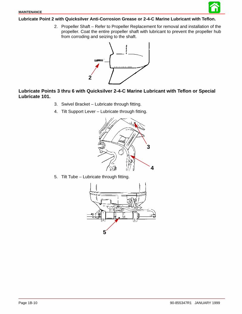
Lubricate Point 2 with Quicksilver Anti-Corrosion Grease or 2-4-C Marine Lubricant with Teflon.
2. Propeller Shaft – Refer to Propeller Replacement for removal and installation of thepropeller. Coat the entire propeller shaft with lubricant to prevent the propeller hubfrom corroding and seizing to the shaft.
2
Lubricate Points 3 thru 6 with Quicksilver 2-4-C Marine Lubricant with Teflon or SpecialLubricate 101.
3. Swivel Bracket – Lubricate through fitting.
4. Tilt Support Lever – Lubricate through fitting.
3
4
5. Tilt Tube – Lubricate through fitting.
5

MAINTENANCE
90-855347R1 JANUARY 1999 Page 1B-11
6. Steering Cable Grease Fitting (If Equipped) – Rotate steering wheel to fully retract thesteering cable end (a) into the outboard tilt tube. Lubricate through fitting (b).
WARNINGThe end of the steering cable must be fully retracted into the outboard tilt tubebefore adding lubricant. Adding lubricant to steering cable when fully extendedcould cause steering cable to become hydraulically locked. An hydraulicallylocked steering cable will cause loss of steering control, possibly resulting in se-rious injury or death.
Lubricate Points 7 With Light Weight Oil.
7. Steering Link Rod Pivot Points – Lubricate pivot points.
7
6-b 6-a
Checking Power Trim Fluid
8. Tilt outboard to the full up position and engage the tilt support lock.
8
9. Remove fill cap and check fluid level. The fluid level should be even with the bottomof the fill hole. Add Quicksilver Power Trim & Steering Fluid. If not available, use auto-motive (ATF) automatic transmission fluid.
9

MAINTENANCE
Page 1B-12 90-855347R1 JANUARY 1999
Gear Case Lubrication
When adding or changing gear case lubricant, visually check for the presence of waterin the lubricant. If water is present, it may have settled to the bottom and will drain out priorto the lubricant, or it may be mixed with the lubricant, giving it a milky colored appearance.If water is noticed, have the gear case checked by your dealer.Water in the lubricant mayresult in premature bearing failure or, in freezing temperatures, will turn to ice and damagethe gear case.
Whenever you remove the fill/drain plug, examine the magnetic end for metal particles.A small amount of metal filings or fine metal particles indicates normal gear wear. An ex-cessive amount of metal filings or larger particles (chips) may indicate abnormal gearwear and should be checked by an authorized dealer.
DRAINING GEAR CASE
NOTE: Some models may have the vent and fill/drain plugs on the opposite side.
1. Place outboard in a vertical operating position.
2. Place drain pan below outboard.
3. Remove vent plug and fill/drain plug and drain lubricant.
2 1
3
GEAR CASE LUBRICANT CAPACITY
Gear case lubricant capacity is approximately 22.5 fl. oz. (666 ml).

MAINTENANCE
90-855347R1 JANUARY 1999 Page 1B-13
CHECKING GEAR CASE LUBRICANT LEVEL AND REFILLING GEAR CASE
NOTE: Some models may have the vent and fill/drain plugs on the opposite side.
1. Place outboard in a vertical operating position.
2. Remove vent plug (a).
3. Place lubricant tube (b) into the fill hole and add lubricant until it appears at the venthole (c).
IMPORTANT: Replace sealing washers if damaged.
4. Stop adding lubricant. Install the vent plug and sealing washer (a) before removingthe lubricant tube.
5. Remove lubricant tube and reinstall cleaned fill/drain plug and sealing washer (d).
1-5
a
cd
b
STORAGE PREPARATION
The major consideration in preparing your outboard for storage is to protect it from rust,corrosion, and damage caused by freezing of trapped water.
The following storage procedures should be followed to prepare your outboard for out ofseason storage or prolonged storage (two months or longer).
CAUTIONNever start or run your outboard (even momentarily) without water circulatingthrough all the cooling water intake holes in the gear case to prevent damage tothe water pump (running dry) or overheating of the engine.
FUEL SYSTEM
IMPORTANT: Gasoline containing alcohol (ethanol or methanol) can cause a for-mation of acid during storage and can damage the fuel system. If the gasoline be-ing used contains alcohol, it is advisable to drain as much of the remaining gaso-line as possible from the fuel tank, remote fuel line, and engine fuel system.
Fill the fuel system (tank, hoses, fuel pumps, and fuel injection systems) with treated (sta-bilized) fuel to help prevent formation of varnish and gum. Proceed with following instruc-tions.
1. Portable Fuel Tank – Pour the required amount of Quicksilver Gasoline Stabilizer (fol-low instructions on container) into fuel tank. Tip fuel tank back and forth to mix stabiliz-er with the fuel.
2. Permanently Installed Fuel Tank – Pour the required amount of Quicksilver GasolineStabilizer (follow instructions on container) into a separate container and mix with ap-proximately one quart (one liter) of gasoline. Pour this mixture into fuel tank.

MAINTENANCE
Page 1B-14 90-855347R1 JANUARY 1999
3. Place the outboard in water or connect flushing attachment for circulating coolingwater. Run the engine at 2000 rpm for 25 minutes to allow treated fuel to fill the fuelsystem.
PROTECTING INTERNAL ENGINE COMPONENTS
NOTE: Make sure the fuel system has been prepared for storage.
1. Remove the spark plugs and add approximately one ounce (30ml) of engine oil intoeach spark plug hole. Rotate the flywheel manually several times to distribute the oilin the cylinders. Reinstall spark plugs.
2. Remove the water separating fuel filter and empty contents into a suitable container.Refer to Maintenance Section for removal and installation of filter. Replace fuel filterannually, or every 100 Hours of operation, or if large amount of fuel contamination ispresent.
PROTECTING EXTERNAL OUTBOARD COMPONENTS
1. Lubricate all outboard components listed in the Inspection and MaintenanceSchedule.
2. Touch up any paint nicks. See your dealer for touch-up paint.
3. Spray Quicksilver Corrosion Guard on external metal surfaces (except corrosion con-trol anodes).
GEAR CASE
Drain and refill the gear case lubricant (refer to maintenance procedure).
POSITIONING OUTBOARD FOR STORAGE
Store outboard in an upright (vertical) position to allow water to drain out of outboard.
CAUTIONIf outboard is stored tilted up in freezing temperature, trapped cooling water orrain water that may have entered the propeller exhaust outlet in the gear casecould freeze and cause damage to the outboard.
BATTERY STORAGE
1. Follow the battery manufacturers instructions for storage and recharging.
2. Remove the battery from the boat and check water level. Recharge if necessary.
3. Store the battery in a cool, dry place.
4. Periodically check the water level and recharge the battery during storage.
1C
GENERAL INFORMATION
90-855347R1 JANUARY 1999 Page 1C-1
IMPORTANT INFORMATIONSection 1C - General Information
Table of Contents
Serial Number Location 1C-1. . . . . . . . . . . . . . . . . . . . . . . Conditions Affecting Performance 1C-2. . . . . . . . . . . . . .
Weather 1C-2. . . . . . . . . . . . . . . . . . . . . . . . . . . . . . . . . . Boat 1C-3. . . . . . . . . . . . . . . . . . . . . . . . . . . . . . . . . . . . . Trim 1C-4. . . . . . . . . . . . . . . . . . . . . . . . . . . . . . . . . . . . . Engine 1C-6. . . . . . . . . . . . . . . . . . . . . . . . . . . . . . . . . . . Engine Compression 1C-6. . . . . . . . . . . . . . . . . . . . . . .
Following Complete Submersion 1C-7. . . . . . . . . . . . . . . Salt Water Submersion 1C-7. . . . . . . . . . . . . . . . . . . . . Submerged While Running 1C-7. . . . . . . . . . . . . . . . .
Model 135/150 DFI Powerhead Front View 1C-9. . . . . . Model 135/150 DFI Powerhead Starboard View 1C-10Model 135/150 DFI Powerhead Port View 1C-11. . . . . . Model 135/150 DFI Powerhead Top View 1C-12. . . . . . Model 135/150 DFI Powerhead Aft View 1C-13. . . . . . Painting Procedures 1C-14. . . . . . . . . . . . . . . . . . . . . . . .
Cleaning & Painting Aluminum Propellers & GearHousings 1C-14. . . . . . . . . . . . . . . . . . . . . . . . . . . . . . .
Decal Application 1C-15. . . . . . . . . . . . . . . . . . . . . . . . . . . Decal Removal 1C-15. . . . . . . . . . . . . . . . . . . . . . . . . . Instructions for “Wet” Application 1C-15. . . . . . . . . .
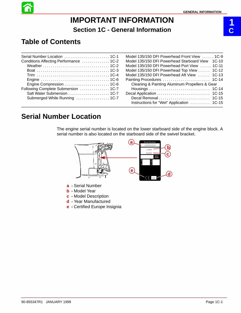
Serial Number Location
The engine serial number is located on the lower starboard side of the engine block. Aserial number is also located on the starboard side of the swivel bracket.
19XX
XX
OGXXXXXX
XXXX
a
ed
cb
a - Serial Numberb - Model Yearc - Model Descriptiond - Year Manufacturede - Certified Europe Insignia
GENERAL INFORMATION
Page 1C-2 90-855347R1 JANUARY 1999
Conditions Affecting Performance
Weather
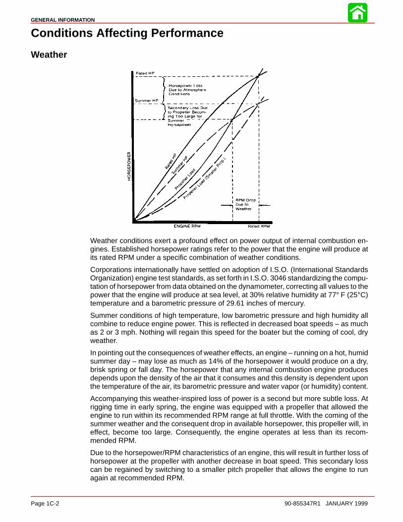
Weather conditions exert a profound effect on power output of internal combustion en-gines. Established horsepower ratings refer to the power that the engine will produce atits rated RPM under a specific combination of weather conditions.
Corporations internationally have settled on adoption of I.S.O. (International StandardsOrganization) engine test standards, as set forth in I.S.O. 3046 standardizing the compu-tation of horsepower from data obtained on the dynamometer, correcting all values to thepower that the engine will produce at sea level, at 30% relative humidity at 77° F (25°C)temperature and a barometric pressure of 29.61 inches of mercury.
Summer conditions of high temperature, low barometric pressure and high humidity allcombine to reduce engine power. This is reflected in decreased boat speeds – as muchas 2 or 3 mph. Nothing will regain this speed for the boater but the coming of cool, dryweather.
In pointing out the consequences of weather effects, an engine – running on a hot, humidsummer day – may lose as much as 14% of the horsepower it would produce on a dry,brisk spring or fall day. The horsepower that any internal combustion engine producesdepends upon the density of the air that it consumes and this density is dependent uponthe temperature of the air, its barometric pressure and water vapor (or humidity) content.
Accompanying this weather-inspired loss of power is a second but more subtle loss. Atrigging time in early spring, the engine was equipped with a propeller that allowed theengine to run within its recommended RPM range at full throttle. With the coming of thesummer weather and the consequent drop in available horsepower, this propeller will, ineffect, become too large. Consequently, the engine operates at less than its recom-mended RPM.
Due to the horsepower/RPM characteristics of an engine, this will result in further loss ofhorsepower at the propeller with another decrease in boat speed. This secondary losscan be regained by switching to a smaller pitch propeller that allows the engine to runagain at recommended RPM.

GENERAL INFORMATION
90-855347R1 JANUARY 1999 Page 1C-3
To obtain optimum engine performance under changing weather conditions, the engineMUST be propped to allow it to operate at or near the top end of the recommended maxi-mum RPM range at wide-open-throttle with a normal boat load.
This will allow the engine to develop full power while operating in an RPM range that dis-courages damaging detonation.
BoatWEIGHT DISTRIBUTION
1. Proper positioning of the weight inside the boat (persons and gear) has a significanteffect on the boat’s performance, for example:
a. Shifting weight to the rear (stern)
(1.)Generally increases top speed.
(2.) If in excess, can cause the boat to porpoise.
(3.)Can make the bow bounce excessively in choppy water.
(4.)Will increase the danger of the following wave splashing into the boat whencoming off plane.
b. Shifting weight to the front (bow)
(1.) Improves ease of planing off.
(2.)Generally improves rough water ride.
(3.) If excessive, can make the boat veer back-and-forth (bow steer).
BOTTOM
1. Boat Bottom: For maximum speed, a boat bottom should be nearly a flat plane whereit contacts the water and particularly straight and smooth in fore-and-aft direction.
a. Hook: Exists when bottom is concave in fore-and -aft direction when viewed fromthe side. When boat is planing, “hook” causes more lift on bottom near transomand allows bow to drop, thus greatly increasing wetted surface and reducing boatspeed. “Hook” frequently is caused by supporting boat too far ahead of transomwhile hauling on a trailer or during storage.
b. Rocker: The reverse of hook and much less common. “Rocker” exists if bottomis convex in fore-and-aft direction when viewed from the side, and boat has strongtendency to porpoise.
c. Surface Roughness: Moss, barnacles, etc., on boat or corrosion of motor’s gearhousing increase skin friction and cause speed loss. Clean surfaces when neces-sary.
d. Gear Housing: If unit is left in the water, marine vegetation may accumulate overa period of time. This growth MUST be removed from unit before operation, as itmay clog the water inlet holes in the gear housing and cause the engine to over-heat.

GENERAL INFORMATION
Page 1C-4 90-855347R1 JANUARY 1999
TrimTRIMMING OUTBOARD “OUT” (“UP”)
WARNINGExcessive trim “out” also may reduce the stability of some high speed hulls. Tocorrect instability at high speed, reduce the power GRADUALLY and trim the out-board “in” slightly before resuming high speed operation. (Rapid reduction inpower will cause a sudden change of steering torque and may cause additionalmomentary boat instability.)
1. Will lift bow of boat, generally increasing top speed.
2. Transfers steering torque harder to left on single outboard installations below 23 in.(584mm) transom height.
3. Increases clearance over submerged objects.
4. In excess, can cause porpoising and/or ventilation.
5. If trimmed out beyond the water pickup, reduced water supply can cause overheatingresulting in engine damage.
GENERAL INFORMATION
90-855347R1 JANUARY 1999 Page 1C-5
TRIMMING OUTBOARD “IN” (“DOWN”) CHARACTERISTICS
WARNINGExcessive speed at minimum trim “in” may cause undesirable and/or unsafesteering conditions. Each boat should be tested for handling characteristics afterany adjustment is made to the angle (trim adjustment bolt relocation.)
1. Will help planing off, particularly with a heavy load.
2. Usually improves ride in choppy water.
3. In excess, can cause boat to veer to the left or right (bow steer).
4. Transfers steering torque harder to right (or less to the left) on single outboard installa-tions.
5. Improves planing speed acceleration (by moving trim adjustment bolt one hole closerto transom).
WATER ABSORPTION
It is imperative that all through hull fasteners be coated with a quality marine sealer at timeof installation. Water intrusion into the transom core and/or inner hull will result in addition-al boat weight (reduced boat performance), hull decay and eventual structural failure.
CAVITATION
Cavitation is caused by water vapor bubbles forming either from a sharp edge or angleon the gear case or from an irregularity in the propeller blade itself. These vapor bubblesflow back and collapse when striking the surface of the propeller blade resulting in the ero-sion of the propeller blade surface. If allowed to continue, eventual blade failure (break-age) will occur.
VENTILATION
Ventilation occurs when air is drawn from the water’s surface (excessive trim out angle)or from the engine exhaust flow (wrong propeller/propeller hardware installed or gearcase labyrinth seal worn) into the propeller blades. These air bubbles strike the propellerblade surface and cause erosion of the blade surface. If allowed to continue, eventualblade failure (breakage) will occur.
GENERAL INFORMATION
Page 1C-6 90-855347R1 JANUARY 1999
EngineDETONATION
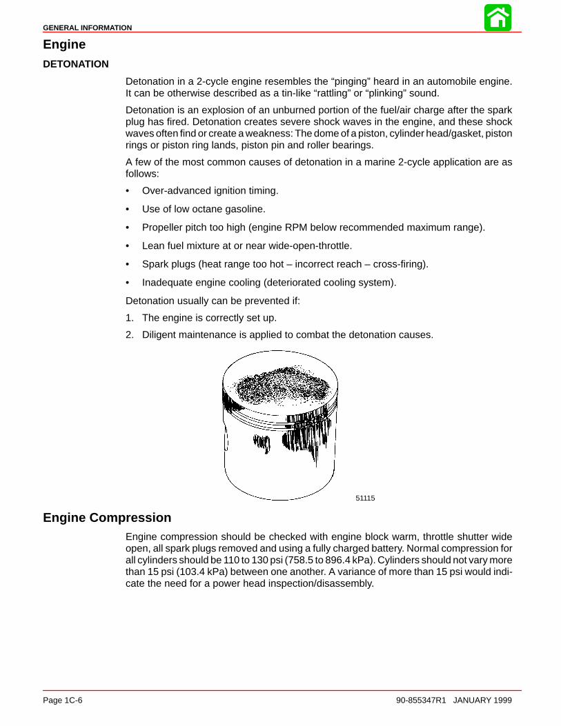
Detonation in a 2-cycle engine resembles the “pinging” heard in an automobile engine.It can be otherwise described as a tin-like “rattling” or “plinking” sound.
Detonation is an explosion of an unburned portion of the fuel/air charge after the sparkplug has fired. Detonation creates severe shock waves in the engine, and these shockwaves often find or create a weakness: The dome of a piston, cylinder head/gasket, pistonrings or piston ring lands, piston pin and roller bearings.
A few of the most common causes of detonation in a marine 2-cycle application are asfollows:
• Over-advanced ignition timing.
• Use of low octane gasoline.
• Propeller pitch too high (engine RPM below recommended maximum range).
• Lean fuel mixture at or near wide-open-throttle.
• Spark plugs (heat range too hot – incorrect reach – cross-firing).
• Inadequate engine cooling (deteriorated cooling system).
Detonation usually can be prevented if:
1. The engine is correctly set up.
2. Diligent maintenance is applied to combat the detonation causes.
51115
Engine CompressionEngine compression should be checked with engine block warm, throttle shutter wideopen, all spark plugs removed and using a fully charged battery. Normal compression forall cylinders should be 110 to 130 psi (758.5 to 896.4 kPa). Cylinders should not vary morethan 15 psi (103.4 kPa) between one another. A variance of more than 15 psi would indi-cate the need for a power head inspection/disassembly.

GENERAL INFORMATION
90-855347R1 JANUARY 1999 Page 1C-7
Following Complete Submersion
Salt Water SubmersionDue to the corrosive effect of salt water on internal engine components, complete disas-sembly is necessary before any attempt is made to start the engine.
Submerged While RunningWhen an engine is submerged while running, the possibility of internal engine damageis greatly increased. If, after engine is recovered and with spark plugs removed, enginefails to turn over freely when turning flywheel, the possibility of internal damage (bent con-necting rod and/or bent crankshaft) exists. If this is the case, the powerhead must be dis-assembled.
SUBMERGED ENGINE (FRESH WATER)
IMPORTANT: Engine should be run within 2 hours after recovery, or serious inter-nal damage may occur. If unable to start engine in this period, disassemble engineand clean all parts. Apply oil as soon as possible.
NOTE: If sand has entered the air intake on the engine, do not attempt to the start theengine. Sand will cause internal engine damage. disassembly is required to clean all in-ternal engine components of sand.
1. Recover engine from water as quickly as possible.
2. Remove cowling.
3. Clean the exterior of the outboard with fresh water.
4. Dry all wiring and electrical components using compressed air.
5. Drain water from fuel system as follows:
a. Disconnect remote fuel hose from engine.
b. Remove drain plug from vapor separator and drain fuel/water. Reinstall plug afterdraining.
c. Remove the fuel hose from bottom of port side fuel rail and drain fuel/water. Rein-stall hose.
d. Remove the water separating fuel filter and empty contents.
6. Drain water from air compressor system as follows:
a. Dry or replace the air filter for the compressor.
b. Remove air outlet hose for the air compressor and drain water from compressorand hose. Reinstall hose.
c. Remove the air hose from bottom of port side fuel rail and drain water. Reinstallhose.
7. Drain water from engine as follows:
a. Remove air sensor from front of the air plenum. Tilt up the outboard and drain wa-ter out of the air plenum through the air sensor mounting hole. Reinstall Sensor.
b. Remove spark plugs from engine.
c. Rotate flywheel manually to blow out any water from the cylinders.
d. Add approximately one ounce (30ml) of engine oil into each spark plug hole. Ro-tate the flywheel manually several times to distribute the oil in the cylinders. Rein-stall spark plugs.
GENERAL INFORMATION
Page 1C-8 90-855347R1 JANUARY 1999
8. Drain water from the oil injection system as follows:
a. Remove remote oil hose (black without blue stripe) from pulse fitting on starboardside of engine.
b. Drain any water from hose and reconnect.
c. If water was present in hose, check for water in the remote oil tank. Drain tank ifwater is present.
9. Disassemble the engine starter motor and dry components.
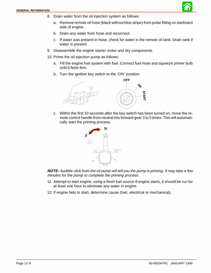
10. Prime the oil injection pump as follows:
a. Fill the engine fuel system with fuel. Connect fuel hose and squeeze primer bulbuntil it feels firm.
b. Turn the ignition key switch to the “ON” position.
c. Within the first 10 seconds after the key switch has been turned on, move the re-mote control handle from neutral into forward gear 3 to 5 times. This will automati-cally start the priming process.
N
F
NOTE: Audible click from the oil pump will tell you the pump is priming. It may take a fewminutes for the pump to complete the priming process.
11. Attempt to start engine, using a fresh fuel source.If engine starts, it should be run forat least one hour to eliminate any water in engine.
12. If engine fails to start, determine cause (fuel, electrical or mechanical).
GENERAL INFORMATION
90-855347R1 JANUARY 1999 Page 1C-9
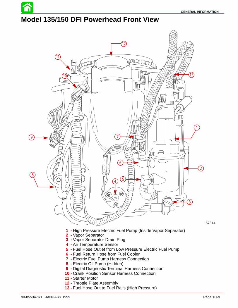
Model 135/150 DFI Powerhead Front View
57314
10
12
11
13
3
2
1
5
6
7
4
8
9
1 - High Pressure Electric Fuel Pump (Inside Vapor Separator)2 - Vapor Separator3 - Vapor Separator Drain Plug4 - Air Temperature Sensor5 - Fuel Hose Outlet from Low Pressure Electric Fuel Pump6 - Fuel Return Hose from Fuel Cooler7 - Electric Fuel Pump Harness Connection8 - Electric Oil Pump (Hidden)9 - Digital Diagnostic Terminal Harness Connection
10 - Crank Position Sensor Harness Connection11 - Starter Motor12 - Throttle Plate Assembly13 - Fuel Hose Out to Fuel Rails (High Pressure)
GENERAL INFORMATION
Page 1C-10 90-855347R1 JANUARY 1999
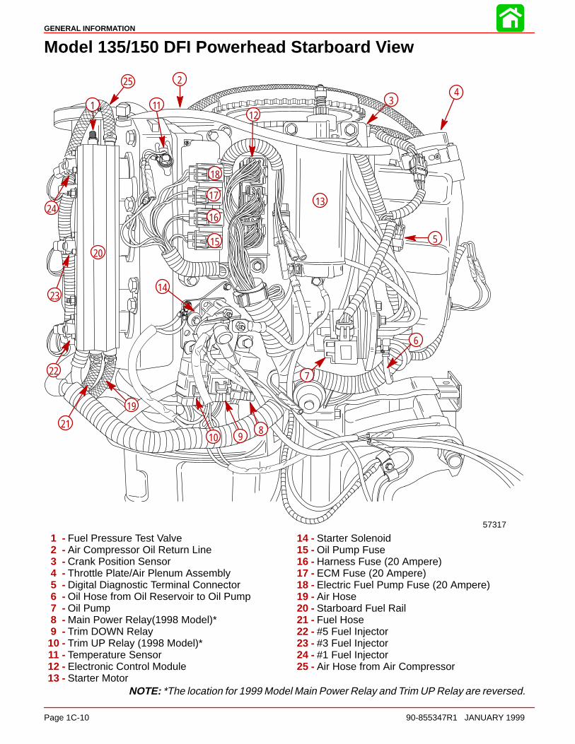
Model 135/150 DFI Powerhead Starboard View
57317
1
2
34
5
6
7
8910
1112
13
14
15
16
17
18
19
20
21
22
23
24
25
1 - Fuel Pressure Test Valve2 - Air Compressor Oil Return Line3 - Crank Position Sensor4 - Throttle Plate/Air Plenum Assembly5 - Digital Diagnostic Terminal Connector6 - Oil Hose from Oil Reservoir to Oil Pump7 - Oil Pump8 - Main Power Relay(1998 Model)*9 - Trim DOWN Relay
10 - Trim UP Relay (1998 Model)*11 - Temperature Sensor12 - Electronic Control Module13 - Starter Motor
14 - Starter Solenoid15 - Oil Pump Fuse16 - Harness Fuse (20 Ampere)17 - ECM Fuse (20 Ampere)18 - Electric Fuel Pump Fuse (20 Ampere)19 - Air Hose20 - Starboard Fuel Rail21 - Fuel Hose22 - #5 Fuel Injector23 - #3 Fuel Injector24 - #1 Fuel Injector25 - Air Hose from Air Compressor
NOTE: *The location for 1999 Model Main Power Relay and Trim UP Relay are reversed.
GENERAL INFORMATION
90-855347R1 JANUARY 1999 Page 1C-11
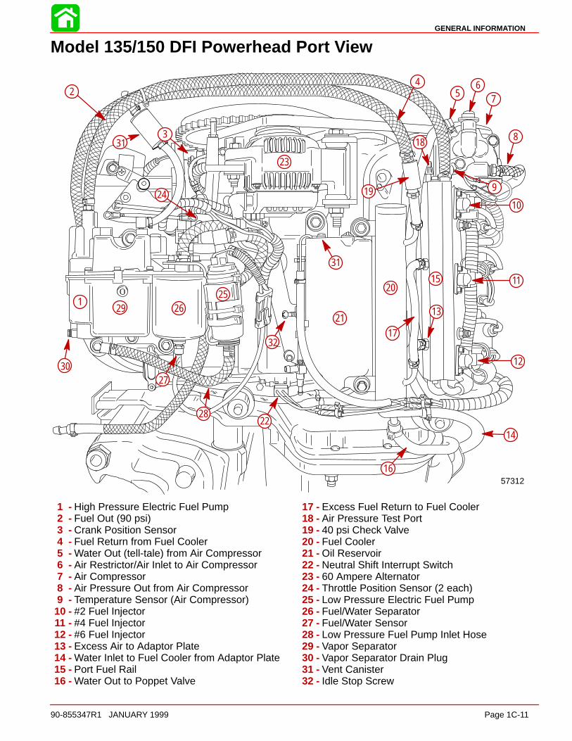
Model 135/150 DFI Powerhead Port View
57312
2
3
1
15
45
67
8
9
10
11
12
13
14
16
17
18
19
20
21
22
23
24
2526
27
28
29
30
31
31
32
1 - High Pressure Electric Fuel Pump2 - Fuel Out (90 psi)3 - Crank Position Sensor4 - Fuel Return from Fuel Cooler5 - Water Out (tell-tale) from Air Compressor6 - Air Restrictor/Air Inlet to Air Compressor7 - Air Compressor8 - Air Pressure Out from Air Compressor9 - Temperature Sensor (Air Compressor)
10 - #2 Fuel Injector11 - #4 Fuel Injector12 - #6 Fuel Injector13 - Excess Air to Adaptor Plate14 - Water Inlet to Fuel Cooler from Adaptor Plate15 - Port Fuel Rail16 - Water Out to Poppet Valve
17 - Excess Fuel Return to Fuel Cooler18 - Air Pressure Test Port19 - 40 psi Check Valve20 - Fuel Cooler21 - Oil Reservoir22 - Neutral Shift Interrupt Switch23 - 60 Ampere Alternator24 - Throttle Position Sensor (2 each)25 - Low Pressure Electric Fuel Pump26 - Fuel/Water Separator27 - Fuel/Water Sensor28 - Low Pressure Fuel Pump Inlet Hose29 - Vapor Separator30 - Vapor Separator Drain Plug31 - Vent Canister32 - Idle Stop Screw
GENERAL INFORMATION
Page 1C-12 90-855347R1 JANUARY 1999
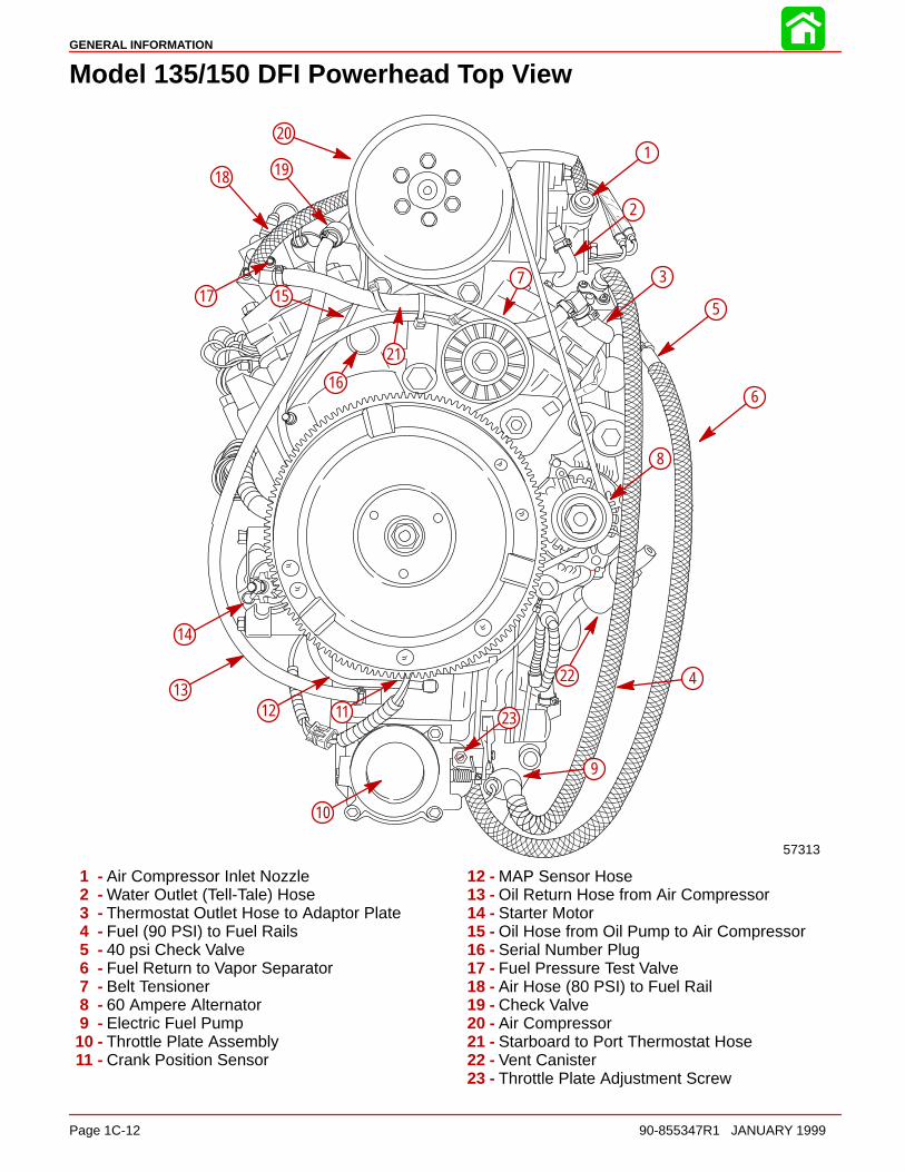
Model 135/150 DFI Powerhead Top View
57313
1
2
3
5
6
7
8
9
10
111213
14
15
16
17
18 19
20
21
22
23
4
1 - Air Compressor Inlet Nozzle2 - Water Outlet (Tell-Tale) Hose3 - Thermostat Outlet Hose to Adaptor Plate4 - Fuel (90 PSI) to Fuel Rails5 - 40 psi Check Valve6 - Fuel Return to Vapor Separator7 - Belt Tensioner8 - 60 Ampere Alternator9 - Electric Fuel Pump
10 - Throttle Plate Assembly11 - Crank Position Sensor
12 - MAP Sensor Hose13 - Oil Return Hose from Air Compressor14 - Starter Motor15 - Oil Hose from Oil Pump to Air Compressor16 - Serial Number Plug17 - Fuel Pressure Test Valve18 - Air Hose (80 PSI) to Fuel Rail19 - Check Valve20 - Air Compressor21 - Starboard to Port Thermostat Hose22 - Vent Canister23 - Throttle Plate Adjustment Screw

GENERAL INFORMATION
90-855347R1 JANUARY 1999 Page 1C-13
Model 135/150 DFI Powerhead Aft View
57315
17
25
1
3
4
5
67
8
9
10
11
12
2
1314
15
16
18
19
2021
2223
24
26
27
28
1 - Air Compressor Restrictor/Air Inlet2 - Water Out (tell-tale) from Air Compressor3 - Air Compressor Oil Inlet from Oil Pump4 - Air Compressor5 - Air Pressure Out (80 psi)6 - Fuel Pressure Test Valve7 - Check Valve8 - Excess Oil Return from Air Compressor9 - #1 Fuel Injector
10 - Starboard Fuel Rail11 - #3 Fuel Injector12 - #5 Fuel Injector13 - Tell-Tale Outlet14 - Flush Plug
15 - #5 Ignition Coil16 - #3 Ignition Coil17 - #1 Ignition Coil18 - Water Inlet to Air Compressor19 - #2 Ignition Coil20 - MAP Sensor21 - #4 Ignition Coil22 - #6 Ignition Coil23 - #6 Fuel Injector24 - Air Regulator25 - Port Fuel Rail26 - #4 Fuel Injector27 - Fuel Regulator28 - #2 Fuel Injector

GENERAL INFORMATION
Page 1C-14 90-855347R1 JANUARY 1999
Painting Procedures
Cleaning & Painting Aluminum Propellers & Gear Housings
WARNINGAvoid serious injury from flying debris. Avoid serious injury from airborne par-ticles. Use eye and breathing protection with proper ventilation.
PROPELLERS
1. Sand the entire area to be painted with 3M 120 Regalite Polycut or coarse Scotch-Brite, disc or belts.
2. Feather edges of all broken paint edges. Try not to sand through the primer.
3. Clean the surface to be painted using PPG Industries DX330 Wax and Grease Re-mover or equivalent (Xylene or M.E.K.).
4. If bare metal has been exposed, use Quicksilver’s Light Gray Primer.
5. Allow a minimum of 1 hour dry time and no more than 1 week before applying the finishcoat.
6. Apply the finish coat using Quicksilver’s EDP Propeller Black.
GEAR HOUSINGS
The following procedures should be used in refinishing gear housings. This procedure willprovide the most durable paint system available in the field. The materials recommendedare of high quality and approximate marine requirements. The following procedure willprovide a repaint job that compares with a properly applied factory paint finish. It is recom-mended that the listed materials be purchased from a local Ditzler Automotive Finish Sup-ply Outlet. The minimum package quantity of each material shown following is sufficientto refinish several gear housings.
Procedure:
1. Wash gear housing with a muriatic acid base cleaner to remove any type of marinegrowth, and rinse with water, if necessary.
2. Wash gear housing with soap and water, then rinse.
3. Sand blistered area with 3M 180 grit sandpaper or P180 Gold Film Disc to removepaint blisters only. Feather edge all broken paint edges.
4. Clean gear housing thoroughly with (DX-330) wax and grease remover.
5. Spot repair surfaces where bare metal is exposed with (DX-503) alodine treatment.
IMPORTANT: Do not use any type of aerosol spray paints as the paint will not prop-erly adhere to the surface nor will the coating be sufficiently thick to resist futurepaint blistering.
6. Mix epoxy chromate primer (DP-40) with equal part catalyst (DP-401) per manufac-turers instructions, allowing proper induction period for permeation of the epoxy prim-er and catalyst.
7. Allow a minimum of one hour drying time and no more than one week before top coat-ing assemblies.
8. Use Ditzler Urethane DU9000 for Mercury Black, DU34334 for Mariner Grey, andDU35466 for Force Charcoal, and DU33414M for Sea Ray White. Catalyze all fourcolors with Ditzler DU5 catalyst mixed 1:1 ratio. Reduce with solvents per Ditzler label.

GENERAL INFORMATION
90-855347R1 JANUARY 1999 Page 1C-15
CAUTIONBe sure to comply with instructions on the label for ventilation and respirators.Using a spray gun, apply one half to one mil even film thickness. Let dry, flash offfor five minutes and apply another even coat of one half to one mil film thickness.This urethane paint will dry to the touch in a matter of hours, but will remain sensi-tive to scratches and abrasions for a few days.
9. The type of spray gun used will determine the proper reduction ratio of the paint.
IMPORTANT: Do not paint sacrificial zinc trim tab or zinc anode.
10. Cut out a cardboard “plug” for trim tab pocket to keep paint off of mating surface tomaintain good continuity circuitry between trim tab and gear housing.
Decal Application
Decal Removal1. Mark decal location before removal to assure proper alignment of new decal.
2. Carefully soften decal and decal adhesive with a heat gun or heat blower while re-moving old decal.
3. Clean decal contact area with a 1:1 mixture of isopropyl alcohol and water.
4. Thoroughly dry decal contact area and check for a completely cleaned surface.
Instructions for “Wet” ApplicationNOTE: The following decal installation instructions are provided for a “Wet” installation.All decals should be applied wet.
TOOLS REQUIRED
1. Plastic Squeegee*
2. Stick Pin
3. Dish Washing Liquid/Detergent without ammonia** “Joy” and “Drift” are known tobe compatible for this process.
** Automotive Body Filler Squeegee
** Do not use a soap that contains petroleum based solvents.
SERVICE TIP: Placement of decals using the “Wet” application will allow time toposition decal. Read entire installation instructions on this technique before pro-ceeding.
TEMPERATURE
IMPORTANT: Installation of vinyl decals should not be attempted while in directsunlight. Air and surface temperature should be between 60 °F (15°C) and 100°F(38°C) for best application.
SURFACE PREPARATION
IMPORTANT: Do not use a soap or any petroleum based solvents to clean applica-tion surface.
Clean entire application surface with mild dish washing liquid and water. Rinse surfacethoroughly with clean water.

GENERAL INFORMATION
Page 1C-16 90-855347R1 JANUARY 1999
DECAL APPLICATION
1. Mix 1/2 ounce (16 ml) of dish washing liquid in one gallon (4 l) of cool water to use aswetting solution.
NOTE: Leave protective masking, if present, on the face of decal until final steps of decalinstallation. This will ensure that the vinyl decal keeps it’s shape during installation.
2. Place the decal face down on a clean work surface and remove the paper backingfrom “adhesive side” of decal.
3. Using a spray bottle, flood the entire “adhesive side” of the decal with the pre-mixedwetting solution.
4. Flood area where the decal will be positioned with wetting solution.
5. Position pre-wetted decal on wetted surface and slide into position.
6. Starting at the center of the decal, “lightly” squeegee out the air bubbles and wettingsolution with overlapping strokes to the outer edge of the decal. Continue going overthe decal surface until all wrinkles are gone and adhesive bonds to the cowl surface.
7. Wipe decal surface with soft paper towel or cloth.
8. Wait 10 - 15 minutes.
9. Starting at one corner, “carefully and slowly” pull the masking off the decal surface ata 180° angle.
NOTE: To remove any remaining bubbles, pierce the decal at one end of the bubble withstick pin and press out the entrapped air or wetting solution with your thumb (moving to-ward the puncture).
1D
OUTBOARD MOTOR INSTALLATION
90-855347R1 JANUARY 1999 Page 1D-1
IMPORTANT INFORMATIONSection 1D - Outboard Motor Installation
Table of Contents
Installation Specifications 1D-1. . . . . . . . . . . . . . . . . . . . . . Lifting Outboard 1D-1. . . . . . . . . . . . . . . . . . . . . . . . . . . . . . Installing Outboard to Boat Transom 1D-2. . . . . . . . . . . .
Determining Recommended Outboard MountingHeight 1D-2. . . . . . . . . . . . . . . . . . . . . . . . . . . . . . . . . . .
Installing Outboard 1D-3. . . . . . . . . . . . . . . . . . . . . . . . . . . Drilling Outboard Mounting Holes 1D-3. . . . . . . . . . . . Securing Outboard To Boat Transom 1D-4. . . . . . . . .
Steering Cable 1D-4. . . . . . . . . . . . . . . . . . . . . . . . . . . . . . . Steering Link Rod 1D-5. . . . . . . . . . . . . . . . . . . . . . . . . . . . Electrical, Hoses and Control Cables 1D-6. . . . . . . . . . .
Installation Note 1D-6. . . . . . . . . . . . . . . . . . . . . . . . . . . Remote Wiring Harness 1D-6. . . . . . . . . . . . . . . . . . . . Warning Gauge Harness 1D-7. . . . . . . . . . . . . . . . . . .
Battery Cables 1D-8. . . . . . . . . . . . . . . . . . . . . . . . . . . . . . . Single Outboard 1D-8. . . . . . . . . . . . . . . . . . . . . . . . . . .
Dual Outboard 1D-8. . . . . . . . . . . . . . . . . . . . . . . . . . . . Shift Cable 1D-9. . . . . . . . . . . . . . . . . . . . . . . . . . . . . . . . . .
Counter Rotation Outboards 1D-9. . . . . . . . . . . . . . . . Installation 1D-10. . . . . . . . . . . . . . . . . . . . . . . . . . . . . .
Throttle Cable 1D-12. . . . . . . . . . . . . . . . . . . . . . . . . . . . . Installation 1D-12. . . . . . . . . . . . . . . . . . . . . . . . . . . . . . Front Clamp Reassembly 1D-13. . . . . . . . . . . . . . . . .
Filling Fuel System 1D-14. . . . . . . . . . . . . . . . . . . . . . . . . Oil Injection Set-Up 1D-14. . . . . . . . . . . . . . . . . . . . . . . . .
Filling 1D-14. . . . . . . . . . . . . . . . . . . . . . . . . . . . . . . . . . Priming the Oil Injection Pump 1D-15. . . . . . . . . . . . Purging Air From the Engine Oil Tank 1D-16. . . . . .
Trim “In” Angle Adjustment 1D-16. . . . . . . . . . . . . . . . . . Trim Tab Adjustment 1D-17. . . . . . . . . . . . . . . . . . . . . . . .
Models Without Power Steering 1D-17. . . . . . . . . . . Models With Power Steering 1D-17. . . . . . . . . . . . . .
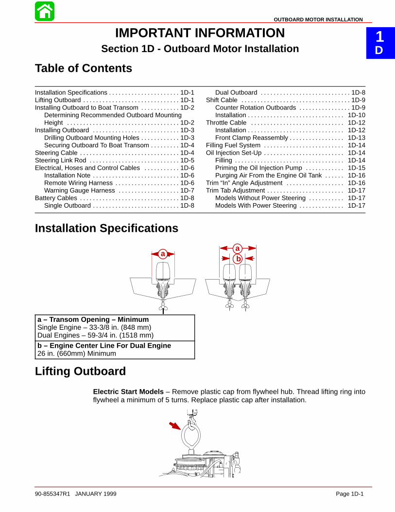
Installation Specifications
aab
aa
a – Transom Opening – MinimumSingle Engine – 33-3/8 in. (848 mm)Dual Engines – 59-3/4 in. (1518 mm)
b – Engine Center Line For Dual Engine26 in. (660mm) Minimum
Lifting Outboard
Electric Start Models – Remove plastic cap from flywheel hub. Thread lifting ring intoflywheel a minimum of 5 turns. Replace plastic cap after installation.
OUTBOARD MOTOR INSTALLATION
Page 1D-2 90-855347R1 JANUARY 1999
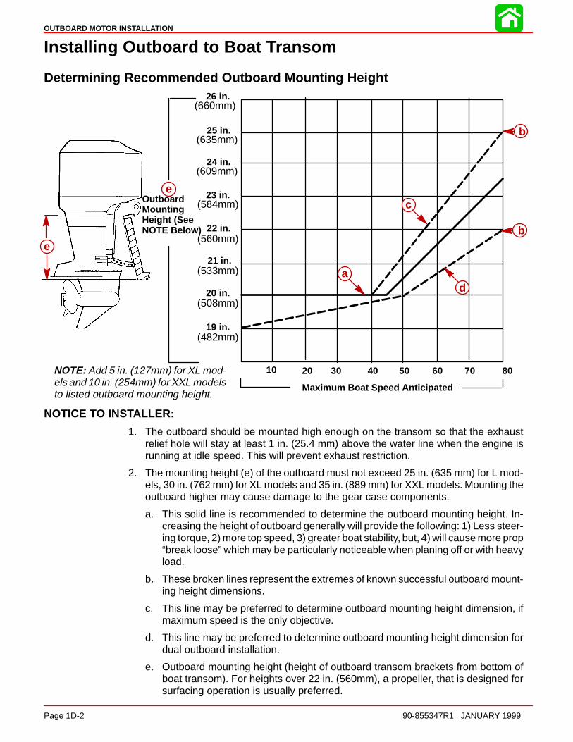
Installing Outboard to Boat Transom
Determining Recommended Outboard Mounting Height
20 in.
21 in.
22 in.
23 in.
24 in.
25 in.
26 in.
19 in.
10 20 30 40 50 60 70 80
Maximum Boat Speed Anticipated
NOTE: Add 5 in. (127mm) for XL mod-els and 10 in. (254mm) for XXL modelsto listed outboard mounting height.
(660mm)
(635mm)
(609mm)
(584mm)
(560mm)
(533mm)
(508mm)
(482mm)
e
e
a
c
d
b
b
OutboardMountingHeight (SeeNOTE Below)
NOTICE TO INSTALLER:
1. The outboard should be mounted high enough on the transom so that the exhaustrelief hole will stay at least 1 in. (25.4 mm) above the water line when the engine isrunning at idle speed. This will prevent exhaust restriction.
2. The mounting height (e) of the outboard must not exceed 25 in. (635 mm) for L mod-els, 30 in. (762 mm) for XL models and 35 in. (889 mm) for XXL models. Mounting theoutboard higher may cause damage to the gear case components.
a. This solid line is recommended to determine the outboard mounting height. In-creasing the height of outboard generally will provide the following: 1) Less steer-ing torque, 2) more top speed, 3) greater boat stability, but, 4) will cause more prop“break loose” which may be particularly noticeable when planing off or with heavyload.
b. These broken lines represent the extremes of known successful outboard mount-ing height dimensions.
c. This line may be preferred to determine outboard mounting height dimension, ifmaximum speed is the only objective.
d. This line may be preferred to determine outboard mounting height dimension fordual outboard installation.
e. Outboard mounting height (height of outboard transom brackets from bottom ofboat transom). For heights over 22 in. (560mm), a propeller, that is designed forsurfacing operation is usually preferred.

OUTBOARD MOTOR INSTALLATION
90-855347R1 JANUARY 1999 Page 1D-3
Installing Outboard
Drilling Outboard Mounting Holes1. Attach (tape) engine mounting template (located with the installation manual) to boat
transom.
IMPORTANT: If using “Transom Drilling Fixture” (part number 91-98234A2), usedrill guide holes marked “A” when drilling outboard mounting holes.
b
a
a - Centerline of Transomb - Transom Drilling Fixture (91-98234A2)
2. Mark and drill four 17/32 in. (13.5mm) mounting holes.
OUTBOARD MOTOR INSTALLATION
Page 1D-4 90-855347R1 JANUARY 1999
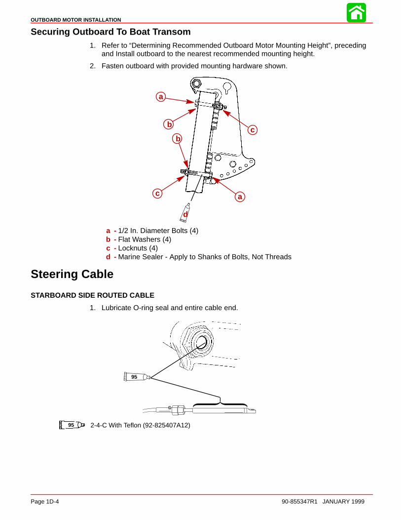
Securing Outboard To Boat Transom1. Refer to “Determining Recommended Outboard Motor Mounting Height”, preceding
and Install outboard to the nearest recommended mounting height.
2. Fasten outboard with provided mounting hardware shown.
d
cb
a
b
c a
a - 1/2 In. Diameter Bolts (4)b - Flat Washers (4)c - Locknuts (4)d - Marine Sealer - Apply to Shanks of Bolts, Not Threads
Steering Cable
STARBOARD SIDE ROUTED CABLE
1. Lubricate O-ring seal and entire cable end.
95
95 2-4-C With Teflon (92-825407A12)

OUTBOARD MOTOR INSTALLATION
90-855347R1 JANUARY 1999 Page 1D-5
2. Insert steering cable into tilt tube.
3. Torque nut to 35 lb. ft. (47.5 N·m).
Steering Link Rod
1. Install steering link rod per illustration.
a
d
c
b
a - Special Bolt (10-90041) Torque to 20 lb-ft (27 N·m)b - Nylon Insert Locknut (11-34863) Torque to 20 lb-ft (27 N·m)c - Flat Washer (2)d - Nylon Insert Locknut (11-34863) Tighten Locknut Until it Seats, Then Back
Nut Off 1/4 TurnIMPORTANT: The steering link rod that connects the steering cable to the enginemust be fastened using special washer head bolt (“a” – Part Number 10-14000) andself locking nuts (“b” & “c” – Part Number 11-34863). These locknuts must neverbe replaced with common nuts (non locking) as they will work loose and vibrateoff freeing the link rod to disengage.
WARNINGDisengagement of a steering link rod can result in the boat taking a full, sudden,sharp turn. This potentially violent action can cause occupants to be thrownoverboard exposing them to serious injury or death.

OUTBOARD MOTOR INSTALLATION
Page 1D-6 90-855347R1 JANUARY 1999
Electrical, Hoses and Control Cables
IMPORTANT: Warning Horn Requirement – The remote control or key switch as-sembly must be wired with a warning horn. This warning horn is used with the en-gine warning system.
Installation NoteOpen the front clamp assembly.
Remote Wiring Harness1. Connect wiring. Place harness into the holder.
GRN/WHTBLU/WHT
BRN/WHTTAN
BLU/WHTGRN/WHT a
a - Power Trim Connections
OUTBOARD MOTOR INSTALLATION
90-855347R1 JANUARY 1999 Page 1D-7
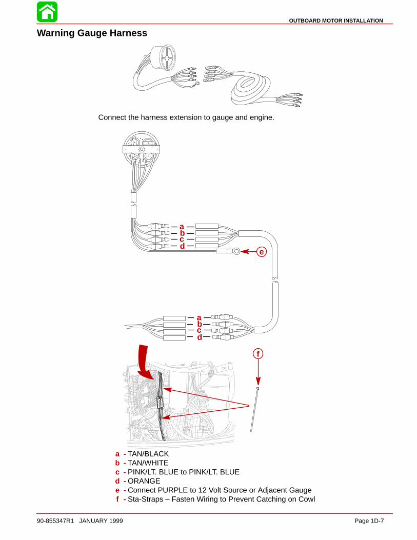
Warning Gauge Harness
Connect the harness extension to gauge and engine.
1
2 3 45
6
a
cb
d
f
e
a
cb
d
a - TAN/BLACKb - TAN/WHITEc - PINK/LT. BLUE to PINK/LT. BLUEd - ORANGEe - Connect PURPLE to 12 Volt Source or Adjacent Gaugef - Sta-Straps – Fasten Wiring to Prevent Catching on Cowl
OUTBOARD MOTOR INSTALLATION
Page 1D-8 90-855347R1 JANUARY 1999
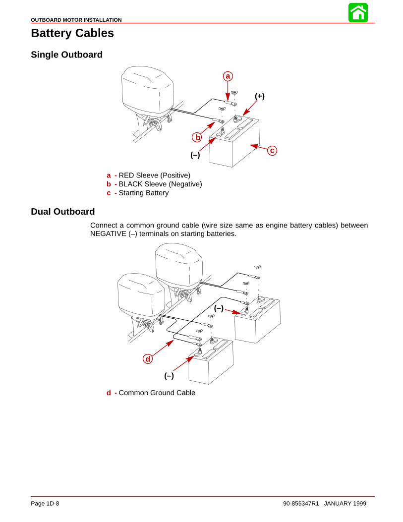
Battery Cables
Single Outboard
(+)
(–)
a
b
c
a - RED Sleeve (Positive)b - BLACK Sleeve (Negative)c - Starting Battery
Dual OutboardConnect a common ground cable (wire size same as engine battery cables) betweenNEGATIVE (–) terminals on starting batteries.
(–)
(–)
d
d - Common Ground Cable
OUTBOARD MOTOR INSTALLATION
90-855347R1 JANUARY 1999 Page 1D-9
Shift Cable
Install cables into the remote control following the instructions provided with the remotecontrol.
NOTE: Install the shift cable to the engine first. The shift cable is the first cable to movewhen the remote control handle is moved out of neutral.
COUNTER ROTATION OUTBOARDS
Counter rotating (left hand) gear cases can be identified by a “L” stamped into the end ofthe propeller shaft.
The Quicksilver Dual Engine Console Mount Control, P/N 88688A22 or 88688A52, is re-quired to shift the counter rotation outboard. The installation instructions shipped with thecontrol explain the procedure required to connect this control to a counter rotation out-board.
IMPORTANT: If the counter rotation outboard is rigged similar to a standard rota-tion outboard OR if a standard rotation outboard is rigged similar to a counter rota-tion outboard, the reverse gear and bearing in the gear case must function as for-ward gear. THE REVERSE GEAR/BEARING ARE NOT DESIGNED TO CARRY THESUSTAINED LOADS THAT ARE GENERATED WHEN RUNNING UNDER CONSTANTHIGH RPM AND THRUST CONDITIONS.
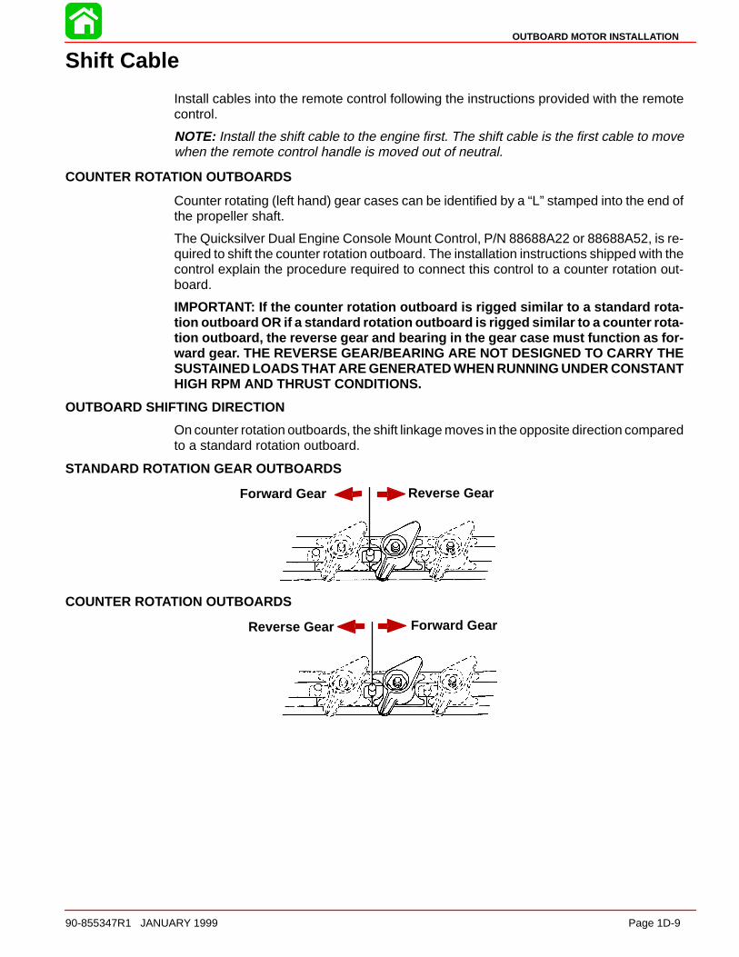
OUTBOARD SHIFTING DIRECTION
On counter rotation outboards, the shift linkage moves in the opposite direction comparedto a standard rotation outboard.
STANDARD ROTATION GEAR OUTBOARDS
Forward Gear Reverse Gear
COUNTER ROTATION OUTBOARDS
Forward GearReverse Gear

OUTBOARD MOTOR INSTALLATION
Page 1D-10 90-855347R1 JANUARY 1999
InstallationIMPORTANT: Step 1 must be followed for proper adjustment of the shift cable.
1. Locate the center point of the slack or lost motion that exists in the shift cable as fol-lows:
a. Move the remote control handle from neutral into forward and advance the handleto full speed position. Slowly return the handle back to the neutral. Place a mark(a) on the cable against the cable end guide.
b. Move the remote control handle from neutral into reverse and advance the handleto full speed position. Slowly return the handle back to the neutral. Place a mark(b) on the cable against the cable end guide.
c. Make a center mark (c), midway between marks (“a” and “b”). Align the cable endguide against this center mark when installing cable to the engine.
STANDARD ROTATION OUTBOARDS
a
b
c
COUNTER ROTATION OUTBOARDS
b
a
c
OUTBOARD MOTOR INSTALLATION
90-855347R1 JANUARY 1999 Page 1D-11
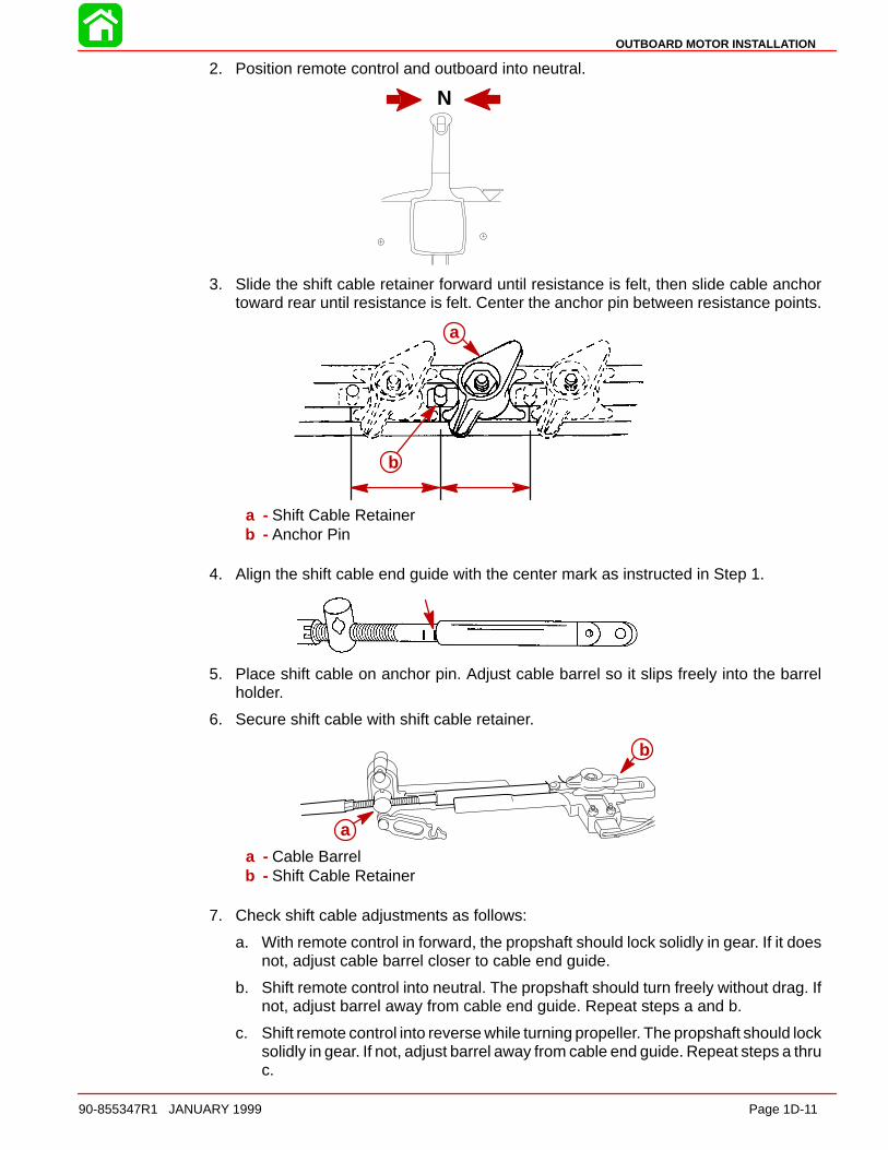
2. Position remote control and outboard into neutral.
N
3. Slide the shift cable retainer forward until resistance is felt, then slide cable anchortoward rear until resistance is felt. Center the anchor pin between resistance points.
b
a
a - Shift Cable Retainerb - Anchor Pin
4. Align the shift cable end guide with the center mark as instructed in Step 1.
5. Place shift cable on anchor pin. Adjust cable barrel so it slips freely into the barrelholder.
6. Secure shift cable with shift cable retainer.
b
a
a - Cable Barrelb - Shift Cable Retainer
7. Check shift cable adjustments as follows:
a. With remote control in forward, the propshaft should lock solidly in gear. If it doesnot, adjust cable barrel closer to cable end guide.
b. Shift remote control into neutral. The propshaft should turn freely without drag. Ifnot, adjust barrel away from cable end guide. Repeat steps a and b.
c. Shift remote control into reverse while turning propeller. The propshaft should locksolidly in gear. If not, adjust barrel away from cable end guide. Repeat steps a thruc.
OUTBOARD MOTOR INSTALLATION
Page 1D-12 90-855347R1 JANUARY 1999
d. Return remote control handle to neutral. The propeller should turn freely withoutdrag. If not, adjust barrel closer to cable end guide. Repeat steps a thru d.
Throttle Cable
INSTALLATION
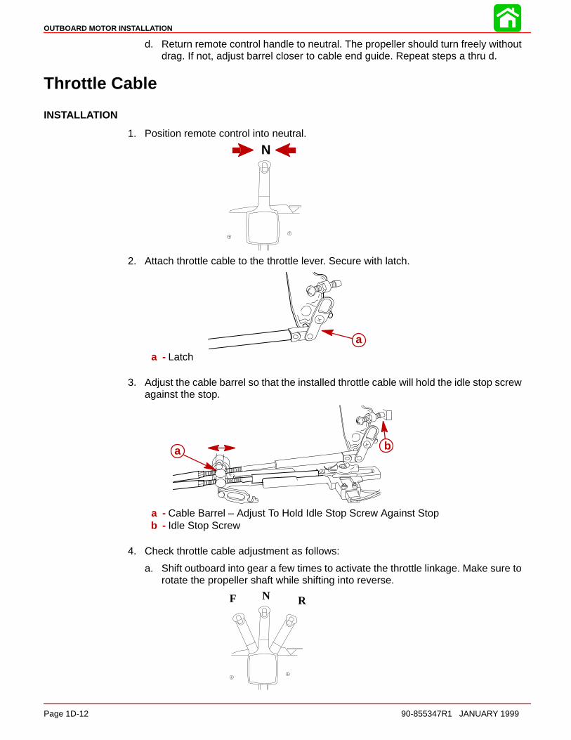
1. Position remote control into neutral.
N
2. Attach throttle cable to the throttle lever. Secure with latch.
a
a - Latch
3. Adjust the cable barrel so that the installed throttle cable will hold the idle stop screwagainst the stop.
a b
a - Cable Barrel – Adjust To Hold Idle Stop Screw Against Stopb - Idle Stop Screw
4. Check throttle cable adjustment as follows:
a. Shift outboard into gear a few times to activate the throttle linkage. Make sure torotate the propeller shaft while shifting into reverse.
N RF
OUTBOARD MOTOR INSTALLATION
90-855347R1 JANUARY 1999 Page 1D-13
b. Return remote control to neutral. Place a thin piece of paper between idle adjust-ment screw and idle stop. Adjustment is correct when the paper can be removedwithout tearing, but has some drag on it. Readjust cable barrel if necessary.
IMPORTANT: The idle stop screw must be touching the stop.
a b
a - Idle Stop Screwb - Idle Stop
5. Lock the barrel holder in place with the cable latch.
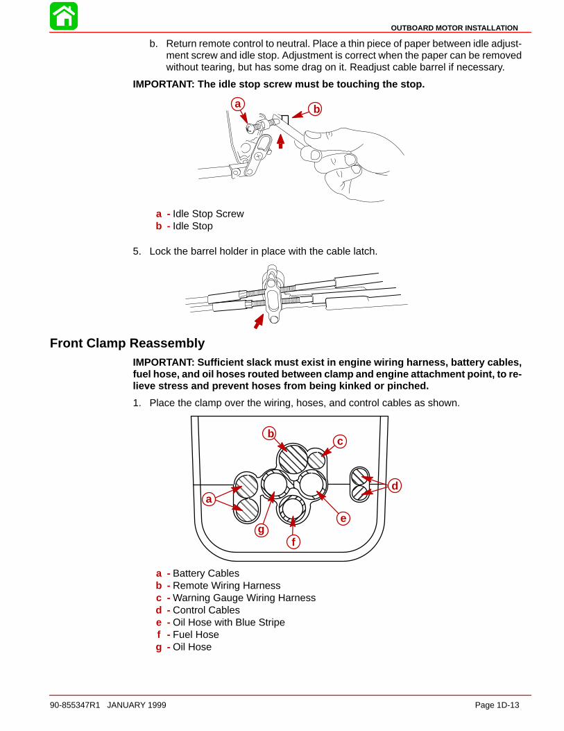
Front Clamp ReassemblyIMPORTANT: Sufficient slack must exist in engine wiring harness, battery cables,fuel hose, and oil hoses routed between clamp and engine attachment point, to re-lieve stress and prevent hoses from being kinked or pinched.
1. Place the clamp over the wiring, hoses, and control cables as shown.
ÇÇÇÇÇÇÇÇÇÉÉÉÉÉÉÉÉÉ
ÇÇÇÇÇÇÇÇÇÇÇÇÇÇÇ
ÇÇÇÇÇÇÇÇÇÉÉÉÉ
ÇÇÇÇÇÇ
bc
da
gf
e
a - Battery Cablesb - Remote Wiring Harnessc - Warning Gauge Wiring Harnessd - Control Cablese - Oil Hose with Blue Stripef - Fuel Hoseg - Oil Hose
OUTBOARD MOTOR INSTALLATION
Page 1D-14 90-855347R1 JANUARY 1999
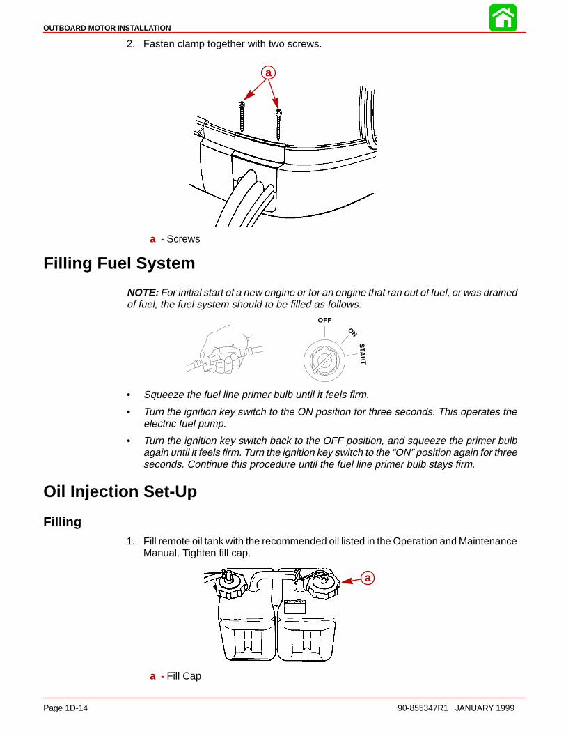
2. Fasten clamp together with two screws.
a
a - Screws
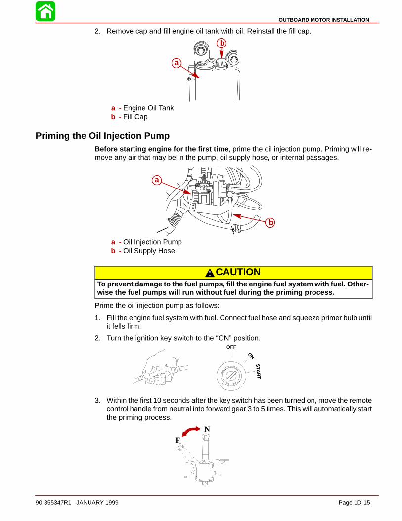
Filling Fuel System
NOTE: For initial start of a new engine or for an engine that ran out of fuel, or was drainedof fuel, the fuel system should to be filled as follows:
• Squeeze the fuel line primer bulb until it feels firm.
• Turn the ignition key switch to the ON position for three seconds. This operates theelectric fuel pump.
• Turn the ignition key switch back to the OFF position, and squeeze the primer bulbagain until it feels firm. Turn the ignition key switch to the “ON” position again for threeseconds. Continue this procedure until the fuel line primer bulb stays firm.
Oil Injection Set-Up
Filling1. Fill remote oil tank with the recommended oil listed in the Operation and Maintenance
Manual. Tighten fill cap.
a
a - Fill Cap
OUTBOARD MOTOR INSTALLATION
90-855347R1 JANUARY 1999 Page 1D-15
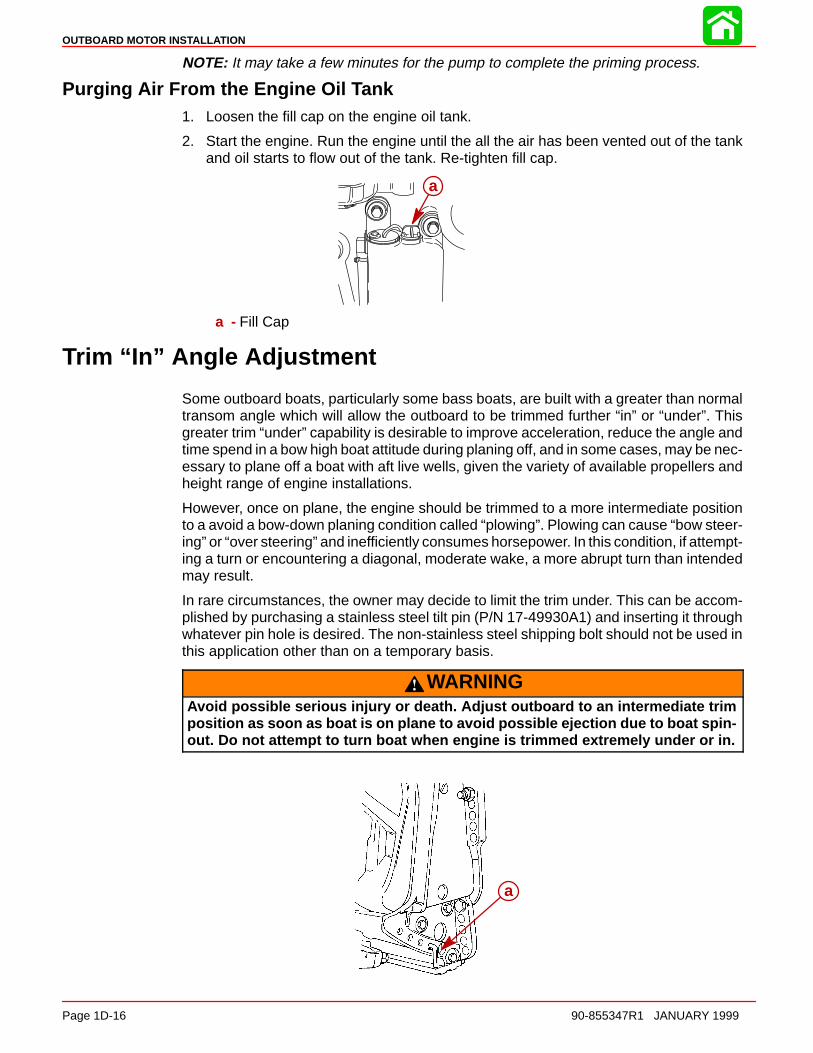
2. Remove cap and fill engine oil tank with oil. Reinstall the fill cap.
a
b
a - Engine Oil Tankb - Fill Cap
Priming the Oil Injection PumpBefore starting engine for the first time , prime the oil injection pump. Priming will re-move any air that may be in the pump, oil supply hose, or internal passages.
a
b
a - Oil Injection Pumpb - Oil Supply Hose
CAUTIONTo prevent damage to the fuel pumps, fill the engine fuel system with fuel. Other-wise the fuel pumps will run without fuel during the priming process.
Prime the oil injection pump as follows:
1. Fill the engine fuel system with fuel. Connect fuel hose and squeeze primer bulb untilit fells firm.
2. Turn the ignition key switch to the “ON” position.
3. Within the first 10 seconds after the key switch has been turned on, move the remotecontrol handle from neutral into forward gear 3 to 5 times. This will automatically startthe priming process.
NF
OUTBOARD MOTOR INSTALLATION
Page 1D-16 90-855347R1 JANUARY 1999
NOTE: It may take a few minutes for the pump to complete the priming process.
Purging Air From the Engine Oil Tank1. Loosen the fill cap on the engine oil tank.
2. Start the engine. Run the engine until the all the air has been vented out of the tankand oil starts to flow out of the tank. Re-tighten fill cap.
a
a - Fill Cap
Trim “In” Angle Adjustment
Some outboard boats, particularly some bass boats, are built with a greater than normaltransom angle which will allow the outboard to be trimmed further “in” or “under”. Thisgreater trim “under” capability is desirable to improve acceleration, reduce the angle andtime spend in a bow high boat attitude during planing off, and in some cases, may be nec-essary to plane off a boat with aft live wells, given the variety of available propellers andheight range of engine installations.
However, once on plane, the engine should be trimmed to a more intermediate positionto a avoid a bow-down planing condition called “plowing”. Plowing can cause “bow steer-ing” or “over steering” and inefficiently consumes horsepower. In this condition, if attempt-ing a turn or encountering a diagonal, moderate wake, a more abrupt turn than intendedmay result.
In rare circumstances, the owner may decide to limit the trim under. This can be accom-plished by purchasing a stainless steel tilt pin (P/N 17-49930A1) and inserting it throughwhatever pin hole is desired. The non-stainless steel shipping bolt should not be used inthis application other than on a temporary basis.
WARNINGAvoid possible serious injury or death. Adjust outboard to an intermediate trimposition as soon as boat is on plane to avoid possible ejection due to boat spin-out. Do not attempt to turn boat when engine is trimmed extremely under or in.
a

OUTBOARD MOTOR INSTALLATION
90-855347R1 JANUARY 1999 Page 1D-17
Trim Tab Adjustment
Propeller steering torque may cause your boat to pull in one direction. This steering torqueresults from your outboard not being trimmed so the propeller shaft is parallel to the watersurface. The trim tab can help compensate for this steering torque and can be adjustedwithin limits to reduce any unequal steering effort.
Models Without Power SteeringOperate your boat at normal cruising speed, trimmed to desired position. Turn your boatleft and right and note the direction the boat turns more easily.
If adjustment is necessary, loosen trim tab bolt until trim tab moves freely (does not rubagainst locking ridges). DO NOT strike tab to make adjustments. Make small adjustmentsat a time. If the boat turns more easily to the left, move the trailing edge of trim tab to theleft. If the boat turns more easily to the right move the trailing edge of trim tab to the right.Position trim tab in one of the locating grooves BEFORE tightening bolt to prevent dam-age to holding mechanism. Torque bolt to 40 lb-ft (54 Nm) and retest.
Models With Power SteeringTrim tab adjustment is not required. The trailing edge of the trim tab should be set straightback.

2A
IGNITION
90-855347R1 JANUARY 1999 Page 2A-1
ELECTRICALSection 2A – Ignition
Table of Contents
Specifications 2A-1. . . . . . . . . . . . . . . . . . . . . . . . . . . . . . . . Special Tools 2A-2. . . . . . . . . . . . . . . . . . . . . . . . . . . . . . . . Electrical Components 2A-4. . . . . . . . . . . . . . . . . . . . . . . . Theory of Operation 2A-6. . . . . . . . . . . . . . . . . . . . . . . . . . Ignition Component Description 2A-6. . . . . . . . . . . . . . . .
Electronic Control Module (ECM) 2A-6. . . . . . . . . . . . Flywheel 2A-7. . . . . . . . . . . . . . . . . . . . . . . . . . . . . . . . . Ignition Coils 2A-7. . . . . . . . . . . . . . . . . . . . . . . . . . . . . . Crank Position Sensor 2A-7. . . . . . . . . . . . . . . . . . . . . Throttle Position Sensor (TPS) 2A-7. . . . . . . . . . . . . . Charging System Alternator 2A-7. . . . . . . . . . . . . . . . . Temperature Sensor 2A-8. . . . . . . . . . . . . . . . . . . . . . . Manifold Absolute Pressure (MAP) Sensor 2A-9. . . Air Temperature Sensor 2A-9. . . . . . . . . . . . . . . . . . . . Direct Injectors 2A-9. . . . . . . . . . . . . . . . . . . . . . . . . . . . Fuel Injectors 2A-9. . . . . . . . . . . . . . . . . . . . . . . . . . . . .
Disconnecting Harness Connectors fromIgnition Coils and/or Injectors 2A-9. . . . . . . . . . . . . . . Troubleshooting 2A-9. . . . . . . . . . . . . . . . . . . . . . . . . . .
Troubleshooting Without Digital DiagnosticTerminal 2A-10. . . . . . . . . . . . . . . . . . . . . . . . . . . . . . . . . . . Troubleshooting With the Digital DiagnosticTerminal 2A-11. . . . . . . . . . . . . . . . . . . . . . . . . . . . . . . . . . . Notes 2A-12. . . . . . . . . . . . . . . . . . . . . . . . . . . . . . . . . . . . . . DDT Functions 2A-13. . . . . . . . . . . . . . . . . . . . . . . . . . . . . . DFI Troubleshooting Guide 2A-15. . . . . . . . . . . . . . . . . . . Ignition Components Removal and Installation 2A-18. .
Flywheel Cover Removal and Installation 2A-18. . . . Electronic Control Module (ECM) 2A-19. . . . . . . . . . . Ignition Module (Coil) 2A-20. . . . . . . . . . . . . . . . . . . . . Crank Position Sensor 2A-21. . . . . . . . . . . . . . . . . . . . Throttle Position Sensors (TPS) 2A-21. . . . . . . . . . . .
Specifications
Ignition Coil Ohm Test
Connect meter leads between primary terminal (GRN/Striped)and ground (BLACK) terminal pin.
0.38 - 0.78
Connect meter leads between spark plug wire/high voltagetower and ground terminal pin.
8.1 - 8.9 k
Temperature Sensor Test (Refer to Chart page 2A-8)
Temperature Sensor(s)Between Black and each TAN/BLK wire. No Continuity
Between each lead and ground No Continuity
Direct Injector Test
Direct Injector Ohm Test (Injector Lead Disconnected)
Connect meter leads between each in-jector terminal pin.
1 - 1.6
Fuel Injector Test
Fuel Injector Ohm Test (Injector Lead Disconnected)
Connect meter leads between each in-jector terminal pin.
1.7 - 1.9

IGNITION
Page 2A-2 90-855347R1 JANUARY 1999
Special Tools
1. Digital Diagnostic Terminal (DDT) 91-823686A2
2. Software Cartridge 91-822608--5
3. DDT Reference Manual 90-825159-3
4. Adaptor Harness 84-822560A5
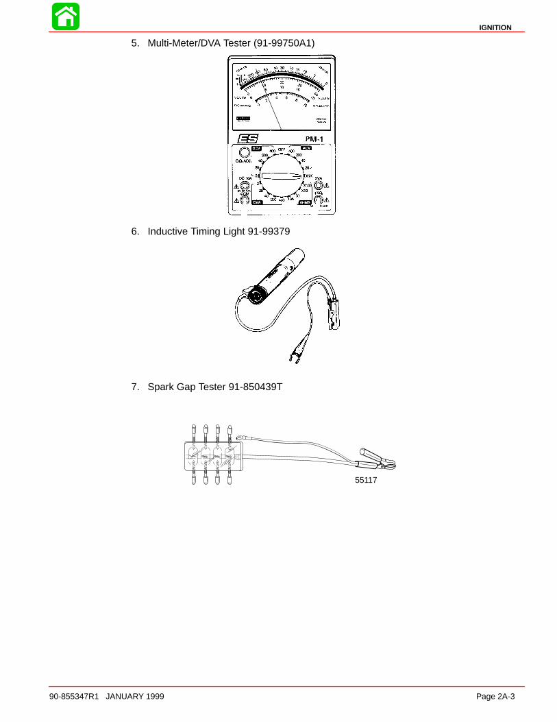
IGNITION
90-855347R1 JANUARY 1999 Page 2A-3
5. Multi-Meter/DVA Tester (91-99750A1)
6. Inductive Timing Light 91-99379
7. Spark Gap Tester 91-850439T
55117
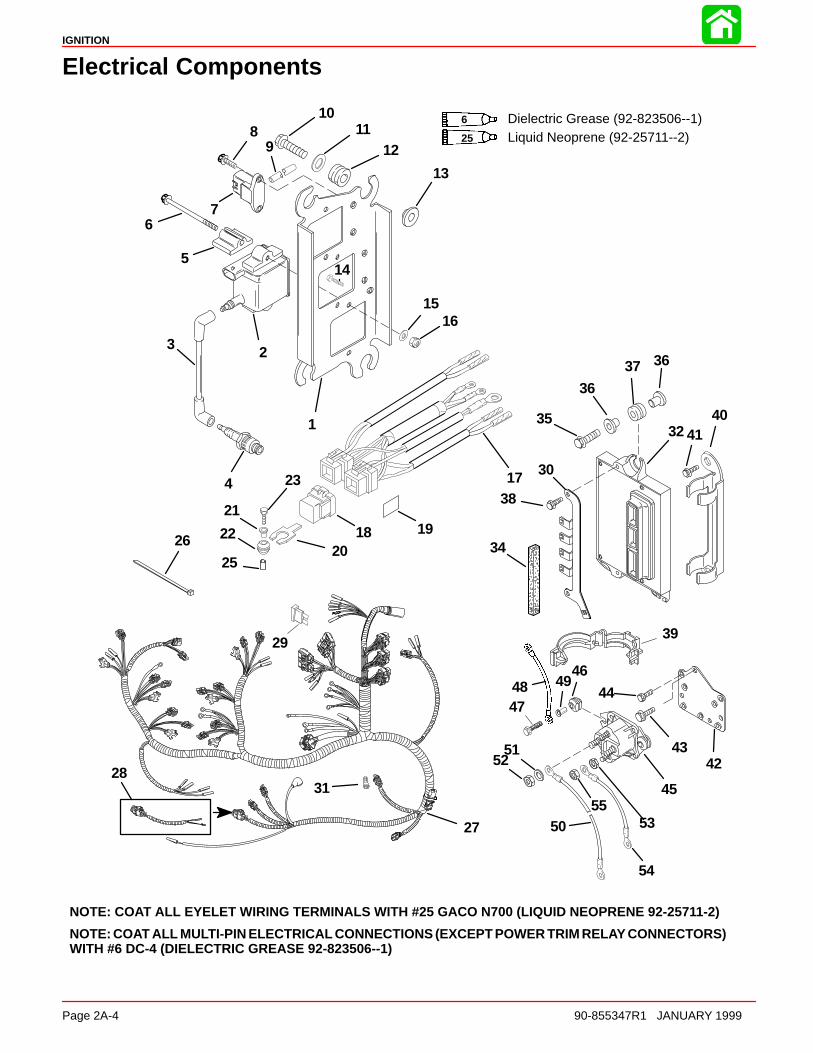
IGNITION
Page 2A-4 90-855347R1 JANUARY 1999
Electrical Components
NOTE: COAT ALL EYELET WIRING TERMINALS WITH #25 GACO N700 (LIQUID NEOPRENE 92-25711-2)
NOTE: COAT ALL MULTI-PIN ELECTRICAL CONNECTIONS (EXCEPT POWER TRIM RELAY CONNECTORS)WITH #6 DC-4 (DIELECTRIC GREASE 92-823506--1)
1
23
4
5
67
89
1011
12
13
14
1516
17
18 19
20
21
22
23
25
26
27
28
29
30
31
32
34
35
3637
38
39
4041
4243
44
45
46
4748 49
50
5152
53
54
55
36
Liquid Neoprene (92-25711--2)6 Dielectric Grease (92-823506--1)25

IGNITION
90-855347R1 JANUARY 1999 Page 2A-5
Electrical Components
REF. TORQUEREF.NO. QTY. DESCRIPTION lb-in lb-ft Nm.
1 1 ELECTRICAL MOUNTING PLATE2 6 IGNITION COIL3 1 HI-TENSION CABLE4 6 SPARK PLUG (HEAVY DUTY) 240 20 275 6 SPACER6 6 SCREW (1/4-20 x 3-1/4 IN.)7 1 MAP SENSOR8 2 SCREW (M6 x 14) 35 49 1 TUBING (31 IN.)
10 4 SCREW (.312-18 x 1-1/4 IN.) 235 19.6 26.511 4 WASHER12 4 GROMMET13 4 BUSHING14 2 SCREW-engine harness ground (M6 x 14) 35 415 6 WASHER16 6 NUT17 1 TRIM HARNESS18 3 RELAY19 3 DECAL-Trim Relay20 3 BRACKET21 3 BUSHING22 3 GROMMET23 2 SCREW (M6 x 25) 35 424 1 SCREW (M6 x 35) 35 425 1 BUSHING26 2 STA STRAP27 1 ENGINE HARNESS28 1 HARNESS (SERVICE ITEM)29 4 FUSE30 1 BRACKET-Fuse Holder31 2 SCREW (M4 x 8)32 1 ECU (135)33 1 ECU (150)34 1 PAD35 3 SCREW (M6 x 25) 70 836 6 BUSHING37 3 GROMMET38 2 SCREW (M6 x 14) 100 11.539 1 CLIP40 1 CLAMP41 2 SCREW (10-16 x 3/8 IN.)42 1 SOLENOID MOUNTING PLATE43 3 SCREW (M6 x 12) 150 1744 2 SCREW (M6 x 14) 35 445 1 STARTER SOLENOID46 2 GROMMET47 2 SCREW (M6 x 25) 35 448 1 CABLE (BLACK)49 2 BUSHING50 1 BATTERY CABLE (POSITIVE)51 2 LOCKWASHER52 2 NUT (5/16-18) 50 5.553 2 NUT (10-32) 8 0.954 1 CABLE55 1 CAP NUT
IGNITION
Page 2A-6 90-855347R1 JANUARY 1999
Theory of Operation
When the ignition key is turned to the RUN position, battery voltage is applied to the mainrelay through the PURPLE wire. When the Electronic Control Module (ECM) receives asignal from the Crank Position Sensor, the main relay ground circuit is completed throughthe ECM. The main relay is then closed and D.C. current from the battery or charging sys-tem is transferred through the main relay 20 Amp fuse to the positive terminal of all 6 igni-tion coil primary windings. The negative terminal of the coil primary is connected to engineground through the Electronic Control Module (ECM). When this circuit is closed, a mag-netic field is allowed to be built up in the ignition coil. The Crank Position Sensor sensesthe location of the 24 teeth on the flywheel and supplies a trigger signal to the ECM. Whenthe ECM receives this signal, the ECM will then open the ground circuit of the coil primary.The magnetic field in the ignition coil primary will then collapse cutting across the coil sec-ondary winding creating a high voltage charge (50,000 volts) that is sent to the spark plug.
Ignition Component Description
Electronic Control Module (ECM)The ECM requires 8 VDC minimum to operate. If the ECM should fail, the engine will stoprunning.
The inputs to the ECM can be monitored and tested by the Digital Diagnostic Terminal91-823686A2 using adaptor harness 84-822560A5.
The ECM performs the following functions:
• Calculates the precise fuel and ignition timing requirements based on engine speed,throttle position, manifold pressure and coolant temperature.
• Controls fuel injectors for each cylinder, direct injectors for each cylinder and ignitionfor each cylinder.
• Controls all alarm horn and warning lamp functions.
• Supplies tachometer signal to gauge.
• Controls RPM limit function.
• Monitors shift interrupt switch.
• Records engine running information.
IGNITION
90-855347R1 JANUARY 1999 Page 2A-7
Flywheel24 teeth under the flywheel ring gear provide engine rpm and crankshaft position informa-tion to the ECM through the crank position sensor.
Ignition CoilsInductive type ignition coils are used on the DFI engines.
Ignition Coil Ohm Test
Connect meter leads between primary terminal (GRN/Striped)and ground (Black) terminal pin.
0.38 - 0.78
Connect meter leads between spark plug wire/high voltagetower and ground terminal pin.
8.1 - 8.9 k
Crank Position SensorSenses 24 teeth located on flywheel under ring gear. Supplies the ECM with crank posi-tion information and engine speed. If sensor should fail, the engine will stop running.
Throttle Position Sensor (TPS)Two (2) Throttle Position Sensors are used in conjunction with one another. If one sensorshould fail, the dash mounted CHECK ENGINE light will light and the warning horn willsound. RPM will be limited to 3000 rpm. If both TPS’s should fail, rpm will be reduced toidle by the ECM. TPS settings are not adjustable. TPS settings can be monitored with theDigital Diagnostic Terminal through the ECM.
Charging System AlternatorBattery charging system is contained within the belt driven alternator, including the regu-lator. At cranking speeds, electrical power for the engine is provided by the boat battery– minimum recommended size is 750 CCA, or 1,000 MCA, cold cranking amperes. Above550 RPM, all electrical power is provided by the alternator. Should engine rpm drop below550 RPM, the alternator is not capable of providing sufficient output and the battery be-comes the primary source of electrical power. Alternator output (when hot) to the battery @ 2000 RPM is approximately 33 - 38 am-peres.

IGNITION
Page 2A-8 90-855347R1 JANUARY 1999
Temperature SensorTwo (2) temperature sensors are used to provide cylinder head temperature informationto the ECM. One sensor is mounted in the starboard cylinder head and one in the air com-pressor cylinder head. The ECM uses this information to increase injector pulse width forcold starts and to retard timing in the event of an over-heat condition.
An ohms test of the temperature sensor would be as follows:
Insert digital or analog ohmmeter test leads into both TAN/BLACK sensor leads. With en-gine at temperature (F) indicated, ohm readings should be as indicated ±10%.
0153045607590
105120135150165180195210225240255270
0 0.2 0.4 0.6 0.8 1.0 1.2 1.4 1.6 1.8 2.0 2.2 2.4 2.6 2.8 3.0 3.2
Resistance (k )
Tem
pera
ture
(F) Temperature Sensor
Temperature Sensor(s)Between Black and each TAN/BLK wire. No Continuity
Between each lead and ground No Continuity

IGNITION
90-855347R1 JANUARY 1999 Page 2A-9
Manifold Absolute Pressure (MAP) SensorThe MAP sensor is mounted between the cylinder heads. A vacuum hose connects themap sensor to the intake manifold. The ECM regulates fuel flow, in part, based on man-ifold absolute pressure. Drawing a vacuum on the MAP sensor hose will create a lean fuelcondition.
Air Temperature SensorThe air temperature sensor is mounted on the intake manifold. The ECM regulates fuelflow, in part, based on manifold air temperature. As air temperature increases, the ECMdecreases fuel flow.
Direct Injectors6 direct injectors (1 per cylinder) are used to inject a fuel/air mix into cylinders. Injectorsare mounted between fuel rails and cylinder heads.
Direct Injector Ohm Test (Injector Lead Disconnected)
Connect meter leads between each in-jector terminal pin.
1 - 1.6
Fuel Injectors6 fuel injectors (1 per cylinder) are used to provide fuel from the fuel rail to the direct injec-tors. The fuel injectors are mounted in the fuel rail.
Fuel Injector Ohm Test (Injector Lead Disconnected)
Connect meter leads between each in-jector terminal pin.
1.7 - 1.9
Disconnecting Harness Connectors from Ignition Coils and/or Injectors
54871
a
a - Wire Clip (push center down to remove)
TroubleshootingThe ECM is designed such that if a sensor fails, the ECM will compensate so that the en-gine does not go into an over-rich condition.
Disconnecting a sensor for troubleshooting purposes may have no noticeable effect.

IGNITION
Page 2A-10 90-855347R1 JANUARY 1999
Troubleshooting Without Digital Diagnostic Terminal
Troubleshooting without the DDT is limited to checking resistance on some of the sen-sors.
Typical failures usually do not involve the ECM. Connectors, set-up, and mechanical wearare most likely at fault.
• Verify spark plug wires are securely installed (pushed in) into the coil tower.
• The engine may not run or may not run above idle with the wrong spark plugs installed.
• Swap ignition coils to see if the problem follows the coil or stays with the particularcylinder.
NOTE: ECMs are capable of performing a cylinder misfire test to isolate problem cylin-ders. Once a suspect cylinder is located, an output load test on the ignition coil, fuel injec-tor and direct injector may be initiated through use of the DDT.
• Any sensor or connection can be disconnected and reconnected while the engine isoperating without damaging the ECM. Disconnecting the crank position sensor willstop the engine.
IMPORTANT: Any sensor that is disconnected while the engine is running will berecorded as a Fault in the ECM Fault History. Use the DDT to view and clear the faulthistory when troubleshooting/repair is completed.
• If all cylinders exhibit similar symptoms, the problem is with a sensor or harness inputto the ECM.
• If problem is speed related or intermittent, it is probably connector or contact related.Inspect connectors for corrosion, loose wires or loose pins. Secure connector seating;use dielectric compound 92-823506-1.
• Inspect the harness for obvious damage: pinched wires, chaffing.
• Secure grounds and all connections involving ring terminals (coat with Liquid Neo-prene 92-25711--3).
• Check fuel pump terminals.
• Check fuel pump pressure.
• Check air compressor pressure.

IGNITION
90-855347R1 JANUARY 1999 Page 2A-11
Troubleshooting with the Digital Diagnostic Terminal
a
bdc
a - Digital Diagnostic Terminal (91-823686A2)b - Software Cartridge (91-822608--4 or --5)c - DDT Reference Manual (90-825159-3)d - Adapter Harness (84-822560A5)
The Quicksilver Digital Diagnostic Terminal (DDT) has been developed specifically tohelp technicians diagnose and repair Mercury Marine 2 and 4 cycle engines.
Attach the diagnostic cable to the ECM diagnostic connector and plug in the software car-tridge. You will be able to monitor sensors and ECM data values including status switches.
The ECM program can help diagnose intermittent engine problems. It will record the stateof the engine sensors and switches for a period of time and then can be played back toreview the recorded information.
Refer to the Digital Diagnostic Terminal Reference Manual for complete diagnostic proce-dures.

IGNITION
Page 2A-12 90-855347R1 JANUARY 1999
Notes:
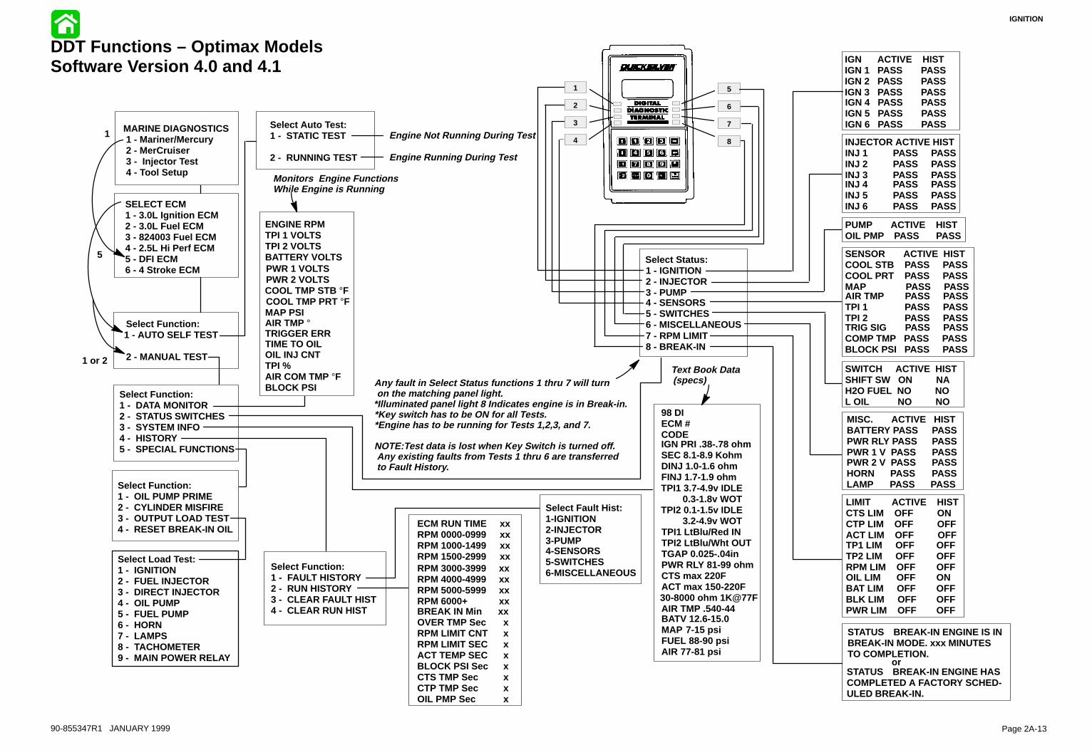
IGNITION
Page 2A-1390-855347R1 JANUARY 1999
DDT Functions – Optimax ModelsSoftware Version 4.0 and 4.1
Select Status:1 - IGNITION2 - INJECTOR3 - PUMP4 - SENSORS5 - SWITCHES6 - MISCELLANEOUS7 - RPM LIMIT8 - BREAK-IN
MARINE DIAGNOSTICS1 - Mariner/Mercury2 - MerCruiser3 - Injector Test4 - Tool Setup
SELECT ECM1 - 3.0L Ignition ECM2 - 3.0L Fuel ECM3 - 824003 Fuel ECM4 - 2.5L Hi Perf ECM5 - DFI ECM6 - 4 Stroke ECM
Select Function:1 - AUTO SELF TEST
2 - MANUAL TEST
Select Function:1 - DATA MONITOR2 - STATUS SWITCHES3 - SYSTEM INFO4 - HISTORY5 - SPECIAL FUNCTIONS
Select Auto Test:1 - STATIC TEST
2 - RUNNING TEST
ENGINE RPMTPI 1 VOLTSTPI 2 VOLTSBATTERY VOLTSPWR 1 VOLTSPWR 2 VOLTSCOOL TMP STB °FCOOL TMP PRT °FMAP PSIAIR TMP °TRIGGER ERRTIME TO OILOIL INJ CNTTPI %AIR COM TMP °FBLOCK PSI
Select Function:1 - FAULT HISTORY2 - RUN HISTORY3 - CLEAR FAULT HIST4 - CLEAR RUN HIST
Select Function:1 - OIL PUMP PRIME2 - CYLINDER MISFIRE3 - OUTPUT LOAD TEST4 - RESET BREAK-IN OIL
98 DI ECM # CODEIGN PRI .38-.78 ohmSEC 8.1-8.9 KohmDINJ 1.0-1.6 ohmFINJ 1.7-1.9 ohmTPI1 3.7-4.9v IDLE
0.3-1.8v WOTTPI2 0.1-1.5v IDLE
3.2-4.9v WOTTPI1 LtBlu/Red INTPI2 LtBlu/Wht OUTTGAP 0.025-.04inPWR RLY 81-99 ohmCTS max 220FACT max 150-220F30-8000 ohm 1K@77FAIR TMP .540-44BATV 12.6-15.0MAP 7-15 psiFUEL 88-90 psiAIR 77-81 psi
Text Book Data(specs)
Monitors Engine FunctionsWhile Engine is Running
SWITCH ACTIVE HISTSHIFT SW ON NAH2O FUEL NO NOL OIL NO NO
PUMP ACTIVE HISTOIL PMP PASS PASS
LIMIT ACTIVE HISTCTS LIM OFF ONCTP LIM OFF OFFACT LIM OFF OFFTP1 LIM OFF OFFTP2 LIM OFF OFFRPM LIM OFF OFFOIL LIM OFF ONBAT LIM OFF OFFBLK LIM OFF OFFPWR LIM OFF OFF
STATUS BREAK-IN ENGINE IS INBREAK-IN MODE. xxx MINUTESTO COMPLETION.
STATUS BREAK-IN ENGINE HASCOMPLETED A FACTORY SCHED-ULED BREAK-IN.
or
MISC. ACTIVE HISTBATTERY PASS PASSPWR RLY PASS PASSPWR 1 V PASS PASSPWR 2 V PASS PASSHORN PASS PASSLAMP PASS PASS
SENSOR ACTIVE HISTCOOL STB PASS PASSCOOL PRT PASS PASSMAP PASS PASSAIR TMP PASS PASSTPI 1 PASS PASSTPI 2 PASS PASSTRIG SIG PASS PASSCOMP TMP PASS PASSBLOCK PSI PASS PASS
INJECTOR ACTIVE HISTINJ 1 PASS PASSINJ 2 PASS PASSINJ 3 PASS PASSINJ 4 PASS PASSINJ 5 PASS PASSINJ 6 PASS PASS
IGN ACTIVE HISTIGN 1 PASS PASSIGN 2 PASS PASSIGN 3 PASS PASSIGN 4 PASS PASSIGN 5 PASS PASSIGN 6 PASS PASS
Engine Not Running During Test
Engine Running During Test
Select Fault Hist:1-IGNITION2-INJECTOR3-PUMP4-SENSORS5-SWITCHES6-MISCELLANEOUSRPM 3000-3999 xx
RPM 4000-4999 xxRPM 5000-5999 xxRPM 6000+ xxBREAK IN Min xxOVER TMP Sec xRPM LIMIT CNT xRPM LIMIT SEC xACT TEMP SEC xBLOCK PSI Sec xCTS TMP Sec xCTP TMP Sec xOIL PMP Sec x
ECM RUN TIME xxRPM 0000-0999 xxRPM 1000-1499 xxRPM 1500-2999 xx
1
2
3
4
5
6
7
8
Any fault in Select Status functions 1 thru 7 will turn on the matching panel light.*Illuminated panel light 8 Indicates engine is in Break-in.*Key switch has to be ON for all Tests. *Engine has to be running for Tests 1,2,3, and 7.
NOTE:Test data is lost when Key Switch is turned off. Any existing faults from Tests 1 thru 6 are transferred to Fault History.
1 or 2
1
5
Select Load Test:1 - IGNITION2 - FUEL INJECTOR3 - DIRECT INJECTOR4 - OIL PUMP5 - FUEL PUMP6 - HORN7 - LAMPS8 - TACHOMETER9 - MAIN POWER RELAY

IGNITION
90-855347R1 JANUARY 1999 Page 2A-15
DFI Troubleshooting Guide
Symptom Cause Action
1. Engine cranks but won’tstart
1.0 Lanyard stop switch in wrong position.
Reset lanyard stop switch.
1.1 Weak battery or bad starter motor, battery voltage drops below 8 volts while cranking (ECM cuts out below 8 volts)(Fuel pump requires 9 Volts).
Replace/charge battery.Inspect condition of starter motor.Check condition of battery termi-nals and cables.
1.2 Low air pressure in rail (less than 70 psi at cranking
Inspect air system for leaks.Inspect air filter for plugging (airpressure measured on port rail).Inspect air compressor reed valvesif necessary.
1.3 No fuel Check that primer bulb is firm.Key-on engine to verify that fuelpump runs for 2 seconds and thenturn off. Measure fuel pressure(valve on starboard rail). Fuel pres-sure should be 10 ± 1 psi greaterthan the air pressure.
1.4 Low fuel pressure Check fuel pressure from low pres-sure electric fuel pump (6–10 psi).Check for fuel leaks. If fuel pres-sure leaks down faster than airpressure, seals on fuel pump maybe leaking. Check air system pres-sure, see 1.2.
1.5 Sheared Flywheel Key Remove flywheel and inspect key.
1.6 Blown fuse Replace fuse. Inspect engine har-ness and electrical components.
1.7 Main Power Relay notfunctioning
Listen for relay to “click” when thekey switch is turned on.
1.8 Spark Plugs Remove fuel pump fuse.Unplug all direct injector connec-tors.Remove spark plugs from eachcylinder.Connect spark plug leads to SparkGap Tester 91-830230T.Crank engine or use DDT outputload test for each ignition coil andobserve spark. If no spark is pres-ent, replace appropriate ignitioncoil. If spark is present, replacespark plugs.

IGNITION
Page 2A-16 90-855347R1 JANUARY 1999
DFI Troubleshooting Guide (continued)
Symptom Cause Action
1. Engine cranks but will notstart (continued)
1.9 ECM not functioning Injection System:Listen for injector “ticking” whencranking or connect spare injectorto each respective harness. Tick-ing should start after 2 crankingrevolutions.
Ignition System:– Check for proper operation by
using Inductive Timing Light91-99379.
– Check battery voltage(RED/YEL Lead) @ ignitioncoils.
– Check for blown fuse (C15).– Check battery voltage to fuse
from main power relay(PURPLE Lead).
– Check for shorted stop wire(BLK/YEL).
– Check crank position sensorsetting [0.015 in. – 0.040 in. (0.38mm – 1.01mm)] fromflywheel or for defective crankposition sensor.
– Defective ECM.
Power Supply:Clean and inspect remote controlmale and female harness connec-tors.
2. Engine cranks, starts andstalls
2.0 Low air pressure in rail See 1.2
2.1 Low fuel pressure in rail See 1.2 and 1.3
2.2 Abnormally high friction inengine
Check for scuffed piston or othersources of high friction.
2.3 Air in fuel system/lines See 1.3 Crank and start engineseveral times to purge.
2.4 TPS malfunction Check motion of throttle arm. Stopnuts should contact block at idleand WOT. Check TPS set-up. Mustconnect DDT with adapter harness(84-822560A5) to ECM.
2.5 Remote control to engineharness connection is poor
Clean and inspect male and fe-male connectors.

IGNITION
90-855347R1 JANUARY 1999 Page 2A-17
DFI Troubleshooting Guide (continued)
Symptom Cause Action
3. Engine idle is rough 3.1 Low air pressure in rail (less than 79 ± 2 psi while running)
See 1.2
3.2 Fouled spark plug Replace spark plug:–If carbon bridges electrode gap
or if it is completely black.–If it is not firing and is wet with
fuel.Note: If spark plug is grey or com-pletely black with aluminum specs,this indicates a scuffed piston.
3.3 Failed direct injector Refer to specifications for ohmtest.
3.4 Failed fuel injector Refer to specifications for ohmtest.
3.5 Bad coil/weak spark Refer to specifications for ohmtest.
3.6 Flywheel key sheared Remove flywheel and inspect key.
4. Engine idles fast (RPM>700) or surges
4.1 Broken fuel pressure regulator or tracker diaphragm
Measure fuel pressure. Removeand inspect diaphragms (a specialtool is required for assembly).
4.2 Fuel leak Check for fuel entering inductionmanifold or air compressor inlet.Fuel pump diaphragm leaking and/or Vapor Separator flooding over.
4.3 Tracker Valve spring missing Inspect tracker valve for proper as-sembly.
4.4 Improper set-up Check throttle cable & cam rolleradjustment.
5. Engine runs rough below3000 rpm
5.1 Fouled spark plug See 3.2
5.2 Low air pressure in rail See 1.2
5.3 Throttle misadjusted Check throttle cam setup on induc-tion manifold. Inspect linkage androller.If throttle plate stop screws havebeen tampered with, contact Mer-cury Marine Service Departmentfor correct adjustment procedures.
5.4 Bad coil/weak spark See 3.5
5.5 TPS malfunction See 2.4
6. Engine runs rough above3000 rpm
6.1 Fouled spark plug See 3.2
6.2 Speed Reduction See 7
6.3 Low air pressure in rails See 1.2
6.4 TPS malfunction See 2.4
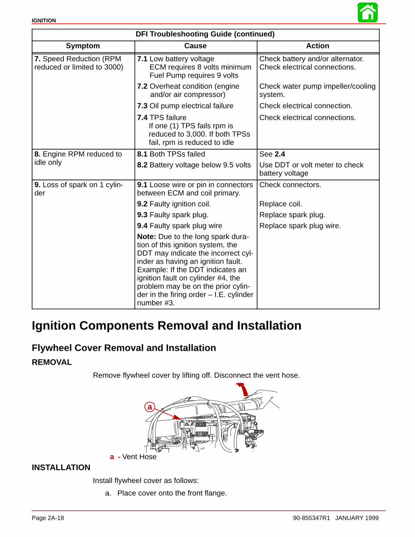
IGNITION
Page 2A-18 90-855347R1 JANUARY 1999
DFI Troubleshooting Guide (continued)
Symptom Cause Action
7. Speed Reduction (RPMreduced or limited to 3000)
7.1 Low battery voltageECM requires 8 volts minimumFuel Pump requires 9 volts
Check battery and/or alternator.Check electrical connections.
7.2 Overheat condition (engineand/or air compressor)
Check water pump impeller/coolingsystem.
7.3 Oil pump electrical failure Check electrical connection.
7.4 TPS failureIf one (1) TPS fails rpm isreduced to 3,000. If both TPSsfail, rpm is reduced to idle
Check electrical connections.
8. Engine RPM reduced toidle only
8.1 Both TPSs failed
8.2 Battery voltage below 9.5 volts
See 2.4Use DDT or volt meter to checkbattery voltage
9. Loss of spark on 1 cylin-der
9.1 Loose wire or pin in connectorsbetween ECM and coil primary.
9.2 Faulty ignition coil.
9.3 Faulty spark plug.
9.4 Faulty spark plug wire
Note: Due to the long spark dura-tion of this ignition system, theDDT may indicate the incorrect cyl-inder as having an ignition fault.Example: If the DDT indicates anignition fault on cylinder #4, theproblem may be on the prior cylin-der in the firing order – I.E. cylindernumber #3.
Check connectors.
Replace coil.
Replace spark plug.
Replace spark plug wire.
Ignition Components Removal and Installation
Flywheel Cover Removal and InstallationREMOVAL
Remove flywheel cover by lifting off. Disconnect the vent hose.
a
a - Vent Hose
INSTALLATION
Install flywheel cover as follows:
a. Place cover onto the front flange.
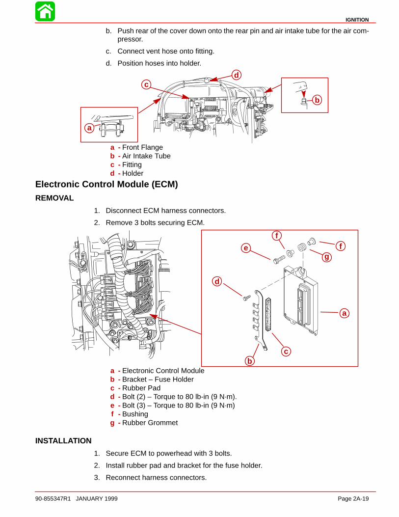
IGNITION
90-855347R1 JANUARY 1999 Page 2A-19
b. Push rear of the cover down onto the rear pin and air intake tube for the air com-pressor.
c. Connect vent hose onto fitting.
d. Position hoses into holder.
a
b
dc
a - Front Flangeb - Air Intake Tubec - Fittingd - Holder
Electronic Control Module (ECM)REMOVAL
1. Disconnect ECM harness connectors.
2. Remove 3 bolts securing ECM.
a
cb
e
f
fg
d
a
bc
d
e
ff
g
a - Electronic Control Moduleb - Bracket – Fuse Holderc - Rubber Padd - Bolt (2) – Torque to 80 lb-in (9 N·m).e - Bolt (3) – Torque to 80 lb-in (9 N·m)f - Bushingg - Rubber Grommet
INSTALLATION
1. Secure ECM to powerhead with 3 bolts.
2. Install rubber pad and bracket for the fuse holder.
3. Reconnect harness connectors.

IGNITION
Page 2A-20 90-855347R1 JANUARY 1999
Ignition Module (Coil)REMOVAL
1. Disconnect coil harness and spark plug lead.
2. Loosen the electrical mounting plate to gain access to the rear locknuts.
3. Remove module attaching bolts.
56141
a
c
b
d
ef
gh
i
j
b
a
b
cb
dj
i
hg
fe
a - Bolts (6) –Torque to 80 lb-in (9 Nm).b - Ignition Coils (6)c - Spacer – Place on Bolts between coilsd - Electrical Mounting Platee - Bolts (4) – Torque to 235 lb-in (27 Nm).f - Washerg - Rubber Grommeth - Bushingi - Washerj - Locknut (6)
INSTALLATION
1. Fasten coils to electrical mounting plate as shown.
2. Reinstall electrical mounting plate.
3. Reconnect spark plug lead and coil harness.
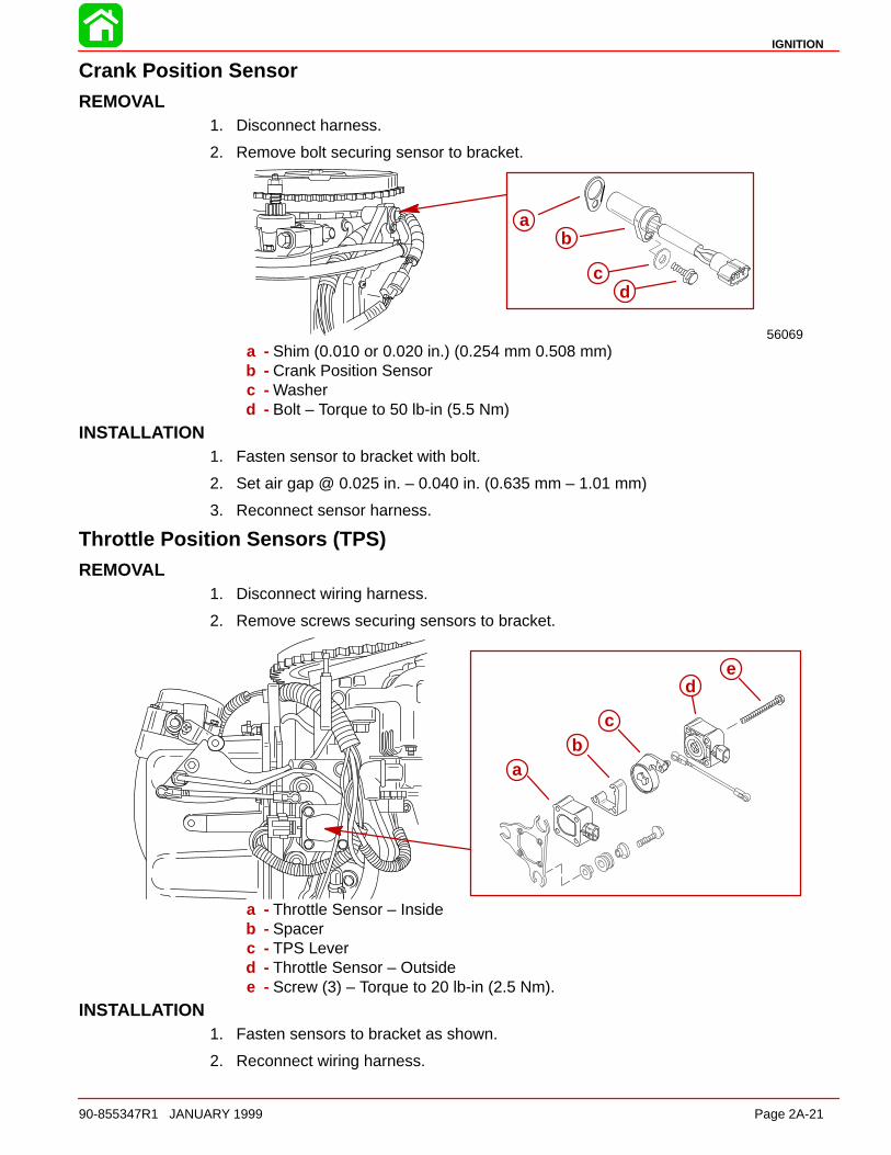
IGNITION
90-855347R1 JANUARY 1999 Page 2A-21
Crank Position SensorREMOVAL
1. Disconnect harness.
2. Remove bolt securing sensor to bracket.
56069
ab
cd
a - Shim (0.010 or 0.020 in.) (0.254 mm 0.508 mm)b - Crank Position Sensorc - Washerd - Bolt – Torque to 50 lb-in (5.5 Nm)
INSTALLATION1. Fasten sensor to bracket with bolt.
2. Set air gap @ 0.025 in. – 0.040 in. (0.635 mm – 1.01 mm)
3. Reconnect sensor harness.
Throttle Position Sensors (TPS)REMOVAL
1. Disconnect wiring harness.
2. Remove screws securing sensors to bracket.
ab
c
de
ab
c
de
a - Throttle Sensor – Insideb - Spacerc - TPS Leverd - Throttle Sensor – Outsidee - Screw (3) – Torque to 20 lb-in (2.5 Nm).
INSTALLATION1. Fasten sensors to bracket as shown.
2. Reconnect wiring harness.
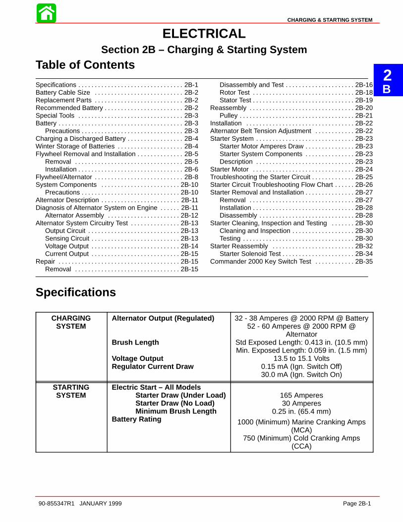
2B
CHARGING & STARTING SYSTEM
90-855347R1 JANUARY 1999 Page 2B-1
ELECTRICALSection 2B – Charging & Starting System
Table of Contents
Specifications 2B-1. . . . . . . . . . . . . . . . . . . . . . . . . . . . . . . . Battery Cable Size 2B-2. . . . . . . . . . . . . . . . . . . . . . . . . . . Replacement Parts 2B-2. . . . . . . . . . . . . . . . . . . . . . . . . . . Recommended Battery 2B-2. . . . . . . . . . . . . . . . . . . . . . . . Special Tools 2B-3. . . . . . . . . . . . . . . . . . . . . . . . . . . . . . . . Battery 2B-3. . . . . . . . . . . . . . . . . . . . . . . . . . . . . . . . . . . . . .
Precautions 2B-3. . . . . . . . . . . . . . . . . . . . . . . . . . . . . . . Charging a Discharged Battery 2B-4. . . . . . . . . . . . . . . . . Winter Storage of Batteries 2B-4. . . . . . . . . . . . . . . . . . . . Flywheel Removal and Installation 2B-5. . . . . . . . . . . . . .
Removal 2B-5. . . . . . . . . . . . . . . . . . . . . . . . . . . . . . . . . Installation 2B-6. . . . . . . . . . . . . . . . . . . . . . . . . . . . . . . .
Flywheel/Alternator 2B-8. . . . . . . . . . . . . . . . . . . . . . . . . . . System Components 2B-10. . . . . . . . . . . . . . . . . . . . . . . .
Precautions 2B-10. . . . . . . . . . . . . . . . . . . . . . . . . . . . . . Alternator Description 2B-11. . . . . . . . . . . . . . . . . . . . . . . . Diagnosis of Alternator System on Engine 2B-11. . . . . .
Alternator Assembly 2B-12. . . . . . . . . . . . . . . . . . . . . . Alternator System Circuitry Test 2B-13. . . . . . . . . . . . . . .
Output Circuit 2B-13. . . . . . . . . . . . . . . . . . . . . . . . . . . . Sensing Circuit 2B-13. . . . . . . . . . . . . . . . . . . . . . . . . . . Voltage Output 2B-14. . . . . . . . . . . . . . . . . . . . . . . . . . . Current Output 2B-15. . . . . . . . . . . . . . . . . . . . . . . . . . .
Repair 2B-15. . . . . . . . . . . . . . . . . . . . . . . . . . . . . . . . . . . . . Removal 2B-15. . . . . . . . . . . . . . . . . . . . . . . . . . . . . . . .
Disassembly and Test 2B-16. . . . . . . . . . . . . . . . . . . . . Rotor Test 2B-18. . . . . . . . . . . . . . . . . . . . . . . . . . . . . . . Stator Test 2B-19. . . . . . . . . . . . . . . . . . . . . . . . . . . . . . .
Reassembly 2B-20. . . . . . . . . . . . . . . . . . . . . . . . . . . . . . . . Pulley 2B-21. . . . . . . . . . . . . . . . . . . . . . . . . . . . . . . . . . .
Installation 2B-22. . . . . . . . . . . . . . . . . . . . . . . . . . . . . . . . . Alternator Belt Tension Adjustment 2B-22. . . . . . . . . . . . Starter System 2B-23. . . . . . . . . . . . . . . . . . . . . . . . . . . . . .
Starter Motor Amperes Draw 2B-23. . . . . . . . . . . . . . . Starter System Components 2B-23. . . . . . . . . . . . . . . Description 2B-23. . . . . . . . . . . . . . . . . . . . . . . . . . . . . .
Starter Motor 2B-24. . . . . . . . . . . . . . . . . . . . . . . . . . . . . . . Troubleshooting the Starter Circuit 2B-25. . . . . . . . . . . . . Starter Circuit Troubleshooting Flow Chart 2B-26. . . . . . Starter Removal and Installation 2B-27. . . . . . . . . . . . . . .
Removal 2B-27. . . . . . . . . . . . . . . . . . . . . . . . . . . . . . . . Installation 2B-28. . . . . . . . . . . . . . . . . . . . . . . . . . . . . . . Disassembly 2B-28. . . . . . . . . . . . . . . . . . . . . . . . . . . . .
Starter Cleaning, Inspection and Testing 2B-30. . . . . . . Cleaning and Inspection 2B-30. . . . . . . . . . . . . . . . . . . Testing 2B-30. . . . . . . . . . . . . . . . . . . . . . . . . . . . . . . . . .
Starter Reassembly 2B-32. . . . . . . . . . . . . . . . . . . . . . . . . Starter Solenoid Test 2B-34. . . . . . . . . . . . . . . . . . . . . .
Commander 2000 Key Switch Test 2B-35. . . . . . . . . . . .
Specifications
CHARGINGSYSTEM
Alternator Output (Regulated)
Brush Length
Voltage OutputRegulator Current Draw
32 - 38 Amperes @ 2000 RPM @ Battery52 - 60 Amperes @ 2000 RPM @
AlternatorStd Exposed Length: 0.413 in. (10.5 mm)Min. Exposed Length: 0.059 in. (1.5 mm)
13.5 to 15.1 Volts0.15 mA (Ign. Switch Off)30.0 mA (Ign. Switch On)
STARTINGSYSTEM
Electric Start – All ModelsStarter Draw (Under Load)Starter Draw (No Load)Minimum Brush Length
Battery Rating
165 Amperes30 Amperes
0.25 in. (65.4 mm)
1000 (Minimum) Marine Cranking Amps(MCA)
750 (Minimum) Cold Cranking Amps(CCA)
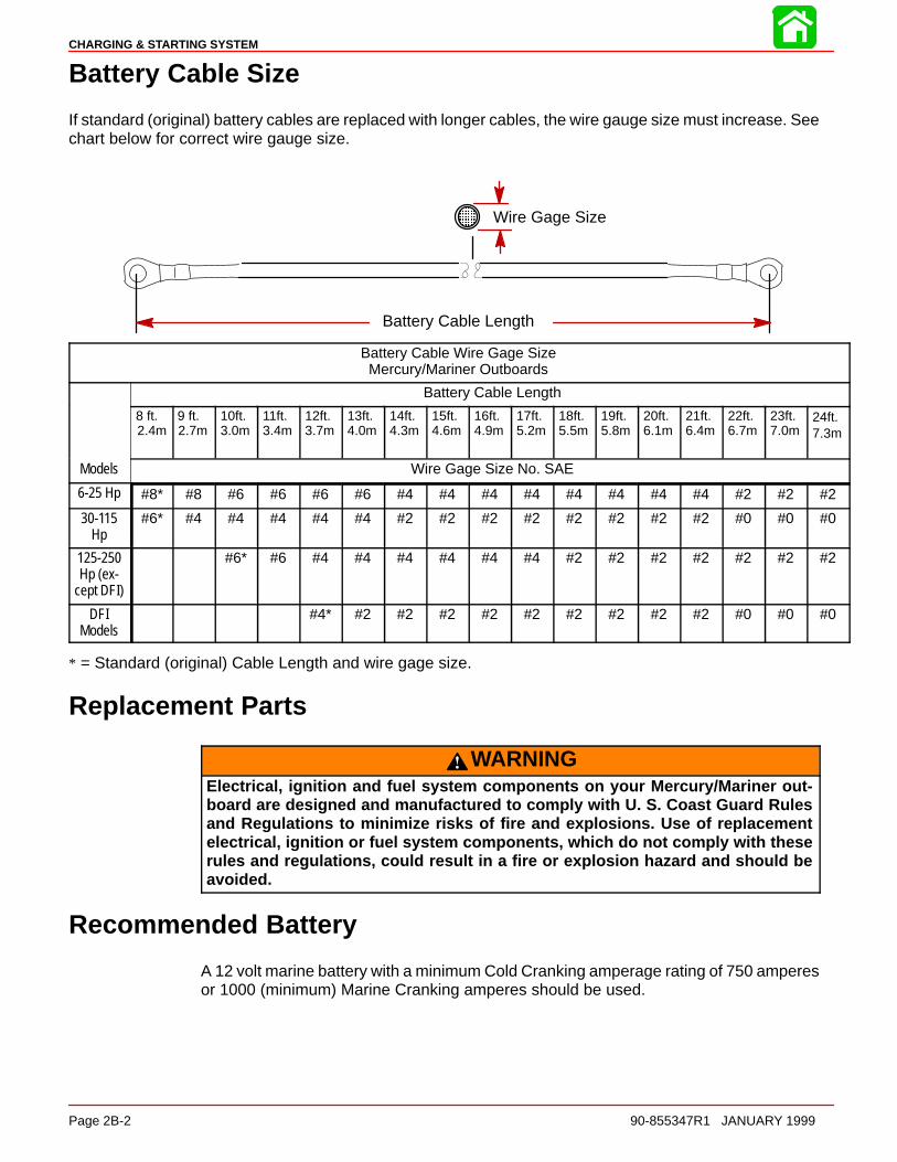
CHARGING & STARTING SYSTEM
Page 2B-2 90-855347R1 JANUARY 1999
Battery Cable Size
If standard (original) battery cables are replaced with longer cables, the wire gauge size must increase. Seechart below for correct wire gauge size.
Battery Cable Length
ÎÎÎÎ
Wire Gage Size
Battery Cable Wire Gage SizeMercury/Mariner Outboards
Battery Cable Length
8 ft.2.4m
9 ft.2.7m
10ft.3.0m
11ft.3.4m
12ft.3.7m
13ft.4.0m
14ft.4.3m
15ft.4.6m
16ft.4.9m
17ft.5.2m
18ft.5.5m
19ft.5.8m
20ft.6.1m
21ft.6.4m
22ft.6.7m
23ft.7.0m
24ft.7.3m
Models Wire Gage Size No. SAE
6-25 Hp #8* #8 #6 #6 #6 #6 #4 #4 #4 #4 #4 #4 #4 #4 #2 #2 #2
30-115Hp
#6* #4 #4 #4 #4 #4 #2 #2 #2 #2 #2 #2 #2 #2 #0 #0 #0
125-250Hp (ex-
cept DFI)
#6* #6 #4 #4 #4 #4 #4 #4 #2 #2 #2 #2 #2 #2 #2
DFIModels
#4* #2 #2 #2 #2 #2 #2 #2 #2 #2 #0 #0 #0
* = Standard (original) Cable Length and wire gage size.
Replacement Parts
WARNINGElectrical, ignition and fuel system components on your Mercury/Mariner out-board are designed and manufactured to comply with U. S. Coast Guard Rulesand Regulations to minimize risks of fire and explosions. Use of replacementelectrical, ignition or fuel system components, which do not comply with theserules and regulations, could result in a fire or explosion hazard and should beavoided.
Recommended Battery
A 12 volt marine battery with a minimum Cold Cranking amperage rating of 750 amperesor 1000 (minimum) Marine Cranking amperes should be used.

CHARGING & STARTING SYSTEM
90-855347R1 JANUARY 1999 Page 2B-3
Special Tools
1. Volt/Ohm Meter 91-99750A1or DMT 2000 Digital Tachometer Multimeter91-854009A1
a b
a - Volt/Ohm Meter 91-99750A1b - DMT 2000 Digital Tachometer Multimeter 91-854009A1
2. Ammeter (60 Ampere minimum) (Obtain locally)
3. Flywheel Holder 91-52344
549644. Protector Cap 91-24161
5. Flywheel Puller 91-73687A1
Battery
Precautions
CAUTIONIf battery acid comes in contact with skin or eyes, wash skin immediately with amild soap. Flush eyes with water immediately and see a doctor.
When charging batteries, an explosive gas mixture forms in each cell. Part of this gas es-capes through holes in vent plugs and may form an explosive atmosphere around batteryif ventilation is poor. This explosive gas may remain in or around battery for several hoursafter it has been charged. Sparks or flames can ignite this gas and cause an internal ex-plosion which may shatter the battery.
The following precautions should be observed to prevent an explosion.

CHARGING & STARTING SYSTEM
Page 2B-4 90-855347R1 JANUARY 1999
1. DO NOT smoke near batteries being charged or which have been charged veryrecently.
2. DO NOT break live circuits at terminals of batteries because a spark usually occursat the point where a live circuit is broken. Always be careful when connecting or dis-connecting cable clamps on chargers. Poor connections are a common cause of elec-trical arcs which cause explosions.
3. DO NOT reverse polarity of battery terminal to cable connections.
Charging a Discharged Battery
WARNINGHydrogen and oxygen gases are produced during normal battery operation orcharging. Sparks or flame can cause this mixture to ignite and explode, if they arebrought near the vent openings. Sulphuric acid in battery can cause seriousburns, if spilled on skin or in eyes. Flush or wash away immediately with clear wa-ter.
The following basic rule applies to any battery charging situation:
1. Any battery may be charged at any rate (in amperes) or as long as spewing of electro-lyte (from violent gassing) does not occur and for as long as electrolyte temperaturedoes not exceed 125° F (52° C). If spewing of electrolyte occurs, or if electrolyte tem-perature exceeds 125° F, charging rate (in amperes) must be reduced or temporarilyhalted to avoid damage to the battery.
2. Battery is fully charged when, over a 2-hour period at a low charging rate (in amperes),all cells are gassing freely (not spewing liquid electrolyte), and no change in specificgravity occurs. Full charge specific gravity is 1.260-1.275, corrected for electrolytetemperature with electrolyte level at 3/16 in. (4.8 mm) over plate, unless electrolyteloss has occurred (from age or over-filling) in which case specific gravity reading willbe lower. For most satisfactory charging, lower charging rates in amperes are recom-mended.
3. If, after prolonged charging, specific gravity of at least 1.230 on all cells cannot bereached, battery is not in optimum condition and will not provide optimum perform-ance; however, it may continue to provide additional service, if it has performed satis-factorily in the past.
4. To check battery voltage while cranking engine with electric starting motor, place RED(+) lead of tester on POSITIVE (+) battery terminal and BLACK (–) lead of tester onNEGATIVE (–) battery terminal. If the voltage drops below 9-1/2 volts while cranking,the battery is weak and should be recharged or replaced.
Winter Storage of Batteries
Battery companies are not responsible for battery damage either in winter storage or indealer stock if the following instructions are not observed:
1. Remove battery from its installation as soon as possible and remove all grease, sul-fate and dirt from top surface by running water over top of battery. Be sure, however,that vent caps are tight beforehand, and blow off all excess water thoroughly with com-pressed air. Check water level, making sure that plates are covered.

CHARGING & STARTING SYSTEM
90-855347R1 JANUARY 1999 Page 2B-5
2. When adding distilled water to battery, be extremely careful not to fill more than 3/16in. (4.8 mm) above perforated baffles inside battery. Battery solution or electrolyte ex-pands from heat caused by charging. Overfilling battery will cause electrolyte to over-flow (if filled beyond 3/16″ above baffles).
3. Grease terminal bolts well with 2-4-C Marine Lubricant and store battery in a COOL-DRY place. Remove battery from storage every 30-45 days, check water level andput on charge for 5 or 6 hours at 6 amperes. DO NOT FAST CHARGE.
4. If specific gravity drops below 1.240, check battery for reason and recharge. Whengravity reaches 1.260, discontinue charging. To check specific gravity, use a hydrom-eter, which can be purchased locally.
5. Repeat preceding charging procedure every 30-45 days, as long as battery is in stor-age, for best possible maintenance during inactive periods to ensure a good service-able battery in spring. When ready to place battery back in service, remove excessgrease from terminals (a small amount is desirable on terminals at all times), rechargeagain as necessary and reinstall battery.
Flywheel Removal and Installation
Removal1. Remove flywheel cover from engine.
WARNINGEngine could possibly start when turning flywheel during removal and installa-tion; therefore, disconnect (and isolate) spark plug leads from spark plugs to pre-vent engine from starting.
2. Disconnect spark plug leads from spark plugs.
3. While holding flywheel with flywheel holder (91-52344), remove flywheel nut andwasher.
57415
a
a - Flywheel Holder (91-25344)
4. Install a crankshaft Protector Cap (91-24161) on end of crankshaft, then install Fly-wheel Puller (91-73687A2) into flywheel.
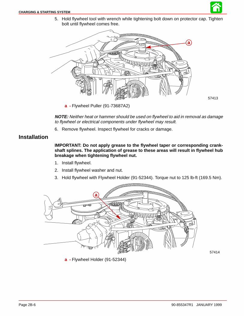
CHARGING & STARTING SYSTEM
Page 2B-6 90-855347R1 JANUARY 1999
5. Hold flywheel tool with wrench while tightening bolt down on protector cap. Tightenbolt until flywheel comes free.
57413
a
a - Flywheel Puller (91-73687A2)
NOTE: Neither heat or hammer should be used on flywheel to aid in removal as damageto flywheel or electrical components under flywheel may result.
6. Remove flywheel. Inspect flywheel for cracks or damage.
InstallationIMPORTANT: Do not apply grease to the flywheel taper or corresponding crank-shaft splines. The application of grease to these areas will result in flywheel hubbreakage when tightening flywheel nut.
1. Install flywheel.
2. Install flywheel washer and nut.
3. Hold flywheel with Flywheel Holder (91-52344). Torque nut to 125 lb-ft (169.5 Nm).
57414
a
a - Flywheel Holder (91-52344)

CHARGING & STARTING SYSTEM
90-855347R1 JANUARY 1999 Page 2B-7
Notes:

CHARGING & STARTING SYSTEM
Page 2B-8 90-855347R1 JANUARY 1999
Flywheel/Alternator
1
2
12
14
23
27
16
4
15
20
1721
25
26
3
22
19
24
18
14
7
8
9
10
11
13
6
55
7
9
4
4
20
5
7
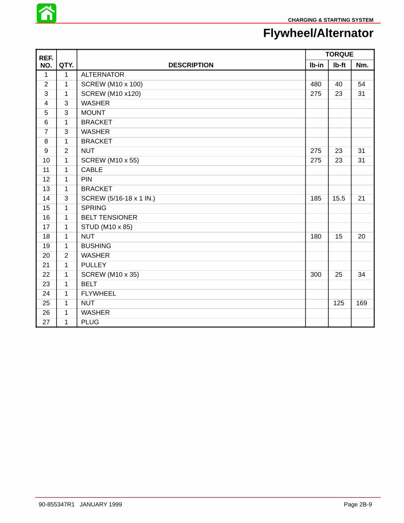
CHARGING & STARTING SYSTEM
90-855347R1 JANUARY 1999 Page 2B-9
Flywheel/Alternator
REF. TORQUEREF.NO. QTY. DESCRIPTION lb-in lb-ft Nm.
1 1 ALTERNATOR
2 1 SCREW (M10 x 100) 480 40 543 1 SCREW (M10 x120) 275 23 314 3 WASHER5 3 MOUNT6 1 BRACKET7 3 WASHER
8 1 BRACKET9 2 NUT 275 23 3110 1 SCREW (M10 x 55) 275 23 3111 1 CABLE12 1 PIN13 1 BRACKET14 3 SCREW (5/16-18 x 1 IN.) 185 15.5 21
15 1 SPRING16 1 BELT TENSIONER17 1 STUD (M10 x 85)18 1 NUT 180 15 2019 1 BUSHING20 2 WASHER21 1 PULLEY
22 1 SCREW (M10 x 35) 300 25 3423 1 BELT24 1 FLYWHEEL25 1 NUT 125 16926 1 WASHER27 1 PLUG

CHARGING & STARTING SYSTEM
Page 2B-10 90-855347R1 JANUARY 1999
System Components
The battery charging system consists of the alternator, battery, ignition switch, startersolenoid and the wiring which connects these components.
51708To
a
d
b
c
a
b
c
d
a - Alternatorb - Batteryc - 20 Ampere Fused - Starter Solenoid
PrecautionsThe following precautions must be observed when working on the alternator system. Fail-ure to observe these precautions may result in serious damage to the alternator system.
1. Do not attempt to polarize the alternator.
2. Do not short across or ground any of the terminals on the alternator, except as specifi-cally instructed.
3. Never disconnect the alternator output lead, regulator harness or battery cables whenthe alternator is being driven by the engine.
4. Always remove NEGATIVE (–) battery cable from battery before working on alternatorsystem.
5. When installing battery, be sure to connect the NEGATIVE (–) (GROUNDED) batterycable to NEGATIVE (–) battery terminal and the POSITIVE (+) battery cable to POSI-TIVE (+) battery terminal.
6. When using a charger or booster battery, connect it in parallel with existing battery(POSITIVE to POSITIVE; NEGATIVE to NEGATIVE).
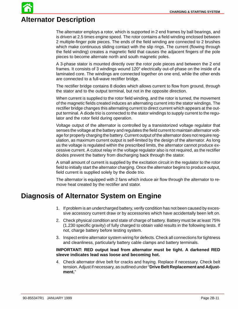
CHARGING & STARTING SYSTEM
90-855347R1 JANUARY 1999 Page 2B-11
Alternator Description
The alternator employs a rotor, which is supported in 2 end frames by ball bearings, andis driven at 2.5 times engine speed. The rotor contains a field winding enclosed between2 multiple-finger pole pieces. The ends of the field winding are connected to 2 brusheswhich make continuous sliding contact with the slip rings. The current (flowing throughthe field winding) creates a magnetic field that causes the adjacent fingers of the polepieces to become alternate north and south magnetic poles.
A 3-phase stator is mounted directly over the rotor pole pieces and between the 2 endframes. It consists of 3 windings wound 120° electrically out-of-phase on the inside of alaminated core. The windings are connected together on one end, while the other endsare connected to a full-wave rectifier bridge.
The rectifier bridge contains 8 diodes which allows current to flow from ground, throughthe stator and to the output terminal, but not in the opposite direction.
When current is supplied to the rotor field winding, and the rotor is turned, the movementof the magnetic fields created induces an alternating current into the stator windings. Therectifier bridge changes this alternating current to direct current which appears at the out-put terminal. A diode trio is connected to the stator windings to supply current to the regu-lator and the rotor field during operation.
Voltage output of the alternator is controlled by a transistorized voltage regulator thatsenses the voltage at the battery and regulates the field current to maintain alternator volt-age for properly charging the battery. Current output of the alternator does not require reg-ulation, as maximum current output is self-limited by the design of the alternator. As longas the voltage is regulated within the prescribed limits, the alternator cannot produce ex-cessive current. A cutout relay in the voltage regulator also is not required, as the rectifierdiodes prevent the battery from discharging back through the stator.
A small amount of current is supplied by the excitation circuit in the regulator to the rotorfield to initially start the alternator charging. Once the alternator begins to produce output,field current is supplied solely by the diode trio.
The alternator is equipped with 2 fans which induce air flow through the alternator to re-move heat created by the rectifier and stator.
Diagnosis of Alternator System on Engine
1. If problem is an undercharged battery, verify condition has not been caused by exces-sive accessory current draw or by accessories which have accidentally been left on.
2. Check physical condition and state of charge of battery. Battery must be at least 75%(1.230 specific gravity) of fully charged to obtain valid results in the following tests. Ifnot, charge battery before testing system.
3. Inspect entire alternator system wiring for defects. Check all connections for tightnessand cleanliness, particularly battery cable clamps and battery terminals.
IMPORTANT: RED output lead from alternator must be tight. A darkened REDsleeve indicates lead was loose and becoming hot.
4. Check alternator drive belt for cracks and fraying. Replace if necessary. Check belttension. Adjust if necessary, as outlined under “Drive Belt Replacement and Adjust-ment. ”
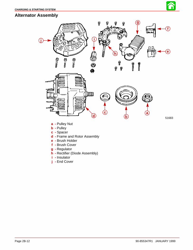
CHARGING & STARTING SYSTEM
Page 2B-12 90-855347R1 JANUARY 1999
Alternator Assembly
51683
j i
g
f
eh
ab
cd
ab
cd
e
f
g
h
ij
a - Pulley Nutb - Pulleyc - Spacerd - Frame and Rotor Assemblye - Brush Holderf - Brush Coverg - Regulatorh - Rectifier (Diode Assembly)i - Insulatorj - End Cover
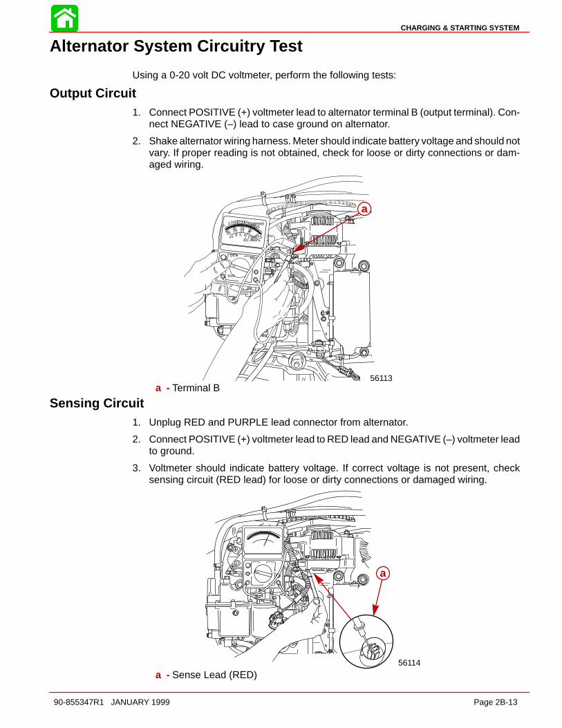
CHARGING & STARTING SYSTEM
90-855347R1 JANUARY 1999 Page 2B-13
Alternator System Circuitry Test
Using a 0-20 volt DC voltmeter, perform the following tests:
Output Circuit1. Connect POSITIVE (+) voltmeter lead to alternator terminal B (output terminal). Con-
nect NEGATIVE (–) lead to case ground on alternator.
2. Shake alternator wiring harness. Meter should indicate battery voltage and should notvary. If proper reading is not obtained, check for loose or dirty connections or dam-aged wiring.
VOLTSDC AMPS
OHMS
0246810
DCVACV
DVA
00510
201030
154020
05101520304060100200
56113
aa
a - Terminal B
Sensing Circuit1. Unplug RED and PURPLE lead connector from alternator.
2. Connect POSITIVE (+) voltmeter lead to RED lead and NEGATIVE (–) voltmeter leadto ground.
3. Voltmeter should indicate battery voltage. If correct voltage is not present, checksensing circuit (RED lead) for loose or dirty connections or damaged wiring.
56114
aa
a - Sense Lead (RED)

CHARGING & STARTING SYSTEM
Page 2B-14 90-855347R1 JANUARY 1999
Voltage Output1. Using a 0-20 volt DC voltmeter, connect POSITIVE (+) lead of voltmeter to TERMINAL
B of alternator and NEGATIVE (–) lead of voltmeter to engine ground.
2. Start engine and allow to warm up. Increase engine RPM from idle to 2000. Normalvoltage output should be 13.5 – 15.1 volts. If voltage reading is greater than normal,replace voltage regulator.
3. If voltage reading is less than normal, fabricate a tool from a piece of stiff wire to thefollowing specifications:
8 in. (203 mm)
13/16 in. (20.6 mm)
0.060 in. (1.52 mm)
VOLTSDC AMPS
OHMS
0246810
DCVACV
DVA
00510
201030154020
05101520304060100200
56113
aa
a - Terminal B
4. Insert bent end of tool through end cover and ground TERMINAL F.
56115
VOLTSDC AMPS
OHMS
02 4 6 8 10
DCVACV
DVA
00510
2010 30
15 4020
05101520304060100200
b
ac
51683
aa
b
ca
a - Terminal Fb - Toolc - Jumper Wire to Engine Ground (Attach to end of Tool)
5. With TERMINAL F grounded, voltage should rise to within the normal range (13.5 –15.1). If voltage rises, replace the regulator.
6. If the voltage DOES NOT rise to within the normal range with TERMINAL F grounded,perform “CURRENT OUTPUT” test.
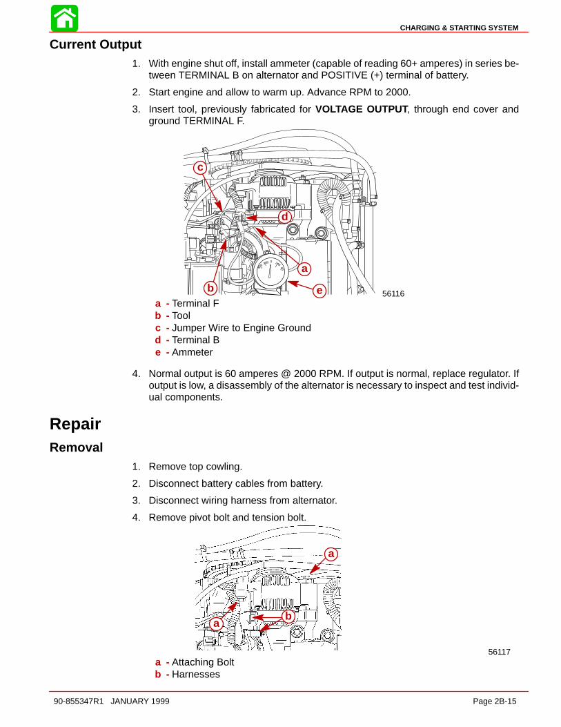
CHARGING & STARTING SYSTEM
90-855347R1 JANUARY 1999 Page 2B-15
Current Output1. With engine shut off, install ammeter (capable of reading 60+ amperes) in series be-
tween TERMINAL B on alternator and POSITIVE (+) terminal of battery.
2. Start engine and allow to warm up. Advance RPM to 2000.
3. Insert tool, previously fabricated for VOLTAGE OUTPUT, through end cover andground TERMINAL F.
56116b e
a
d
c
a - Terminal Fb - Toolc - Jumper Wire to Engine Groundd - Terminal Be - Ammeter
4. Normal output is 60 amperes @ 2000 RPM. If output is normal, replace regulator. Ifoutput is low, a disassembly of the alternator is necessary to inspect and test individ-ual components.
RepairRemoval
1. Remove top cowling.
2. Disconnect battery cables from battery.
3. Disconnect wiring harness from alternator.
4. Remove pivot bolt and tension bolt.
a
a
b
56117
a
ba
a - Attaching Boltb - Harnesses

CHARGING & STARTING SYSTEM
Page 2B-16 90-855347R1 JANUARY 1999
Disassembly and Test1. Remove 3 screws and nut securing end cover and remove insulator and cover.
2. Remove 5 screws securing regulator and brush assembly.
51680
a
b
e
f
g g
51683
c
d
a
b
a
b
c
d
a - Coverb - Screwsc - Nutd - Insulatore - Regulatorf - Brush Assemblyg - Screws
NOTE: Proper regulator operation can be determined by VOLTAGE OUTPUT and CUR-RENT OUTPUT, previous. If regulator does not meet specifications, replace regulator.Torque regulator screws to 17 lb-in (2 Nm).
NOTE: Brushes are replaced as an assembly. Inspect assembly for stuck brushes or ex-cessive brush wear. Normal exposed brush length is 0.156 in. (4.0 mm). Minimum ex-posed brush length is 0.059 in. (1.5 mm).
3. Remove 4 screws securing rectifier (diode assembly) to alternator.
51684b
a
ba - Screwsb - Rectifier (Diode Assembly)
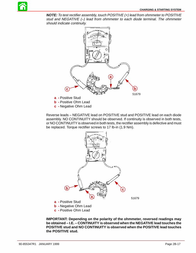
CHARGING & STARTING SYSTEM
90-855347R1 JANUARY 1999 Page 2B-17
NOTE: To test rectifier assembly, touch POSITIVE (+) lead from ohmmeter to POSITIVEstud and NEGATIVE (–) lead from ohmmeter to each diode terminal. The ohmmetershould indicate continuity.
51679
b
a
c
a
bc
a - Positive Studb - Positive Ohm Leadc - Negative Ohm Lead
Reverse leads – NEGATIVE lead on POSITIVE stud and POSITIVE lead on each diodeassembly. NO CONTINUITY should be observed. If continuity is observed in both tests,or NO CONTINUITY is observed in both tests, the rectifier assembly is defective and mustbe replaced. Torque rectifier screws to 17 lb-in (1.9 Nm).
51679
b
a
c
a
b c
a - Positive Studb - Negative Ohm Leadc - Positive Ohm Lead
IMPORTANT: Depending on the polarity of the ohmmeter, reversed readings maybe obtained – I.E. – CONTINUITY is observed when the NEGATIVE lead touches thePOSITIVE stud and NO CONTINUITY is observed when the POSITIVE lead touchesthe POSITIVE stud.

CHARGING & STARTING SYSTEM
Page 2B-18 90-855347R1 JANUARY 1999
IMPORTANT: The regulator, rectifier and brush assembly are the only componentsindividually replaceable on this alternator. If the rotor or stator is defective, the en-tire rotor, stator and housing must be replaced as an assembly.
IMPORTANT: Clean anti-corrosion paint from electrical connections prior to reas-sembly. Coat all electrical connections with LIQUID NEOPRENE (92-25711-1).
Rotor Test1. Inspect slip ring surface for roughness, abnormal wear and/or burning. If such condi-
tions exist, rotor is not considered serviceable and alternator should be replaced.
2. Measure the outer diameter of the slip rings using vernier calipers. STANDARD DI-AMETER: 0.567 in. (14.4 mm); MINIMUM DIAMETER: 0.551 in. (14 mm). If slip ringdiameter is less than minimum, rotor is not considered serviceable and alternatorshould be replaced.
5168051684
aa
a - Slip Rings
3. Inspect rotor for an open circuit. Using an ohmmeter, check for continuity between sliprings. Resistance should not exceed 3 ohms. If no continuity exists, rotor is defective.
4. Check rotor for short to ground. NO CONTINUITY should exist between slip rings androtor shaft. If CONTINUITY exists, rotor is defective.
51683
a
b
51682
aa a
b
a - Slip Ringsb - Rotor Shaft
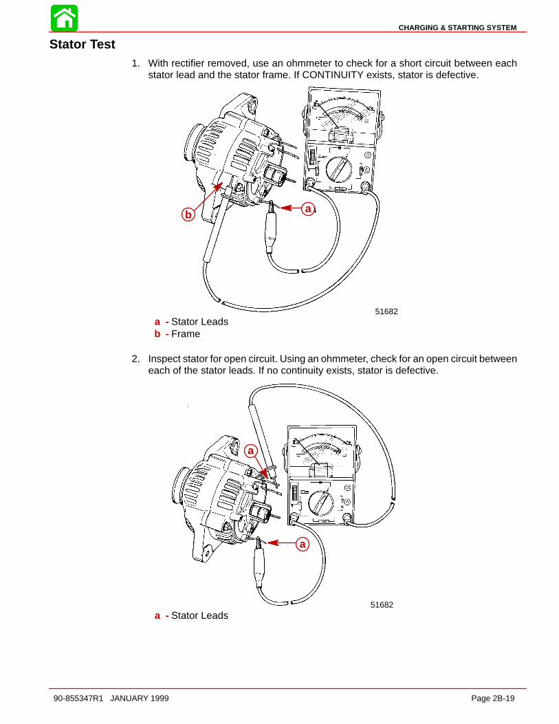
CHARGING & STARTING SYSTEM
90-855347R1 JANUARY 1999 Page 2B-19
Stator Test1. With rectifier removed, use an ohmmeter to check for a short circuit between each
stator lead and the stator frame. If CONTINUITY exists, stator is defective.
51682
baab
a - Stator Leadsb - Frame
2. Inspect stator for open circuit. Using an ohmmeter, check for an open circuit betweeneach of the stator leads. If no continuity exists, stator is defective.
51682
a
aa
a
a - Stator Leads

CHARGING & STARTING SYSTEM
Page 2B-20 90-855347R1 JANUARY 1999
Reassembly1. Position rectifier assembly over stator leads.
2. Form stator leads in a clockwise loop and secure leads to rectifier with 4 screws.Torque screws to 17 lb-in (1.9 Nm).
51684
b
b
a
a
c
c
d
d51683
b
a
b
a
b
b
a - Rectifier Assemblyb - Stator Leadsc - Stator Leadsd - Screws [Torque to 17 lb-in (1.9 Nm)]
3. Secure regulator to alternator with 2 screws [1 in. (25.4 mm) long]; 1 screw [0.25 in.(6.4 mm) long] and lockwashers. DO NOT tighten screws at this time.
4. Secure brush assembly with 2 screws – [0.25 in. (6.4 mm) long] and [0.312 in. (8.0mm) long].
51680
b
c
ad
e
f
51684
c
aa b
c
a - Regulatorb - Screws [1 in. (25.4 mm)]c - Screw [0.25 in. (6.4 mm)]d - Brush Assemblye - Screw [0.25 in. (6.4 mm)]f - Screw [0.312 in. (8.0 mm)]

CHARGING & STARTING SYSTEM
90-855347R1 JANUARY 1999 Page 2B-21
5. Install end cover. Secure cover with 3 screws. Torque screws to 23 lb-in. (2.5 Nm).Install terminal insulator. Torque nut to 36 lb-in (4 Nm).
51683
d
c
a
b
a
b
c
d
a - Coverb - Screw [Torque to 23 lb-in (2.5 Nm)]c - Terminal Insulatord - Nut [Torque to 36 lb-in. (4 Nm)]
Pulley1. While holding rotor shaft, remove pulley nut.
2. Before reinstalling pulley, verify spacer is installed on rotor shaft.
51683
ad
51679
a
c
b
a
b
c
a - Pulleyb - Rotor Shaftc - Nutd - Spacer
3. Torque pulley nut to 50 lb-ft (68 Nm).
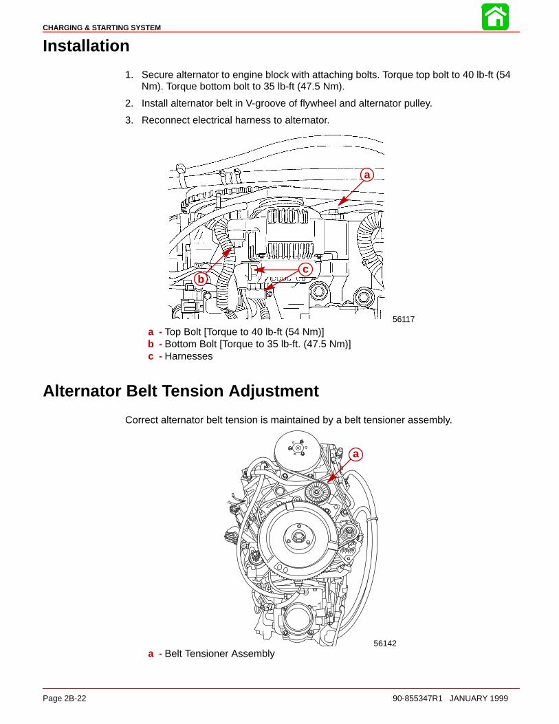
CHARGING & STARTING SYSTEM
Page 2B-22 90-855347R1 JANUARY 1999
Installation
1. Secure alternator to engine block with attaching bolts. Torque top bolt to 40 lb-ft (54Nm). Torque bottom bolt to 35 lb-ft (47.5 Nm).
2. Install alternator belt in V-groove of flywheel and alternator pulley.
3. Reconnect electrical harness to alternator.
a
56117
bc
a
bc
a - Top Bolt [Torque to 40 lb-ft (54 Nm)]b - Bottom Bolt [Torque to 35 lb-ft. (47.5 Nm)]c - Harnesses
Alternator Belt Tension Adjustment
Correct alternator belt tension is maintained by a belt tensioner assembly.
a
56142
a
a - Belt Tensioner Assembly

CHARGING & STARTING SYSTEM
90-855347R1 JANUARY 1999 Page 2B-23
Starter System
Starter Motor Amperes DrawSTARTER MOTOR NO LOAD NORMALPART NO. AMP. DRAW AMP. DRAW50-833153-1 30 AMPS 165 AMPS
Starter System Components1. Battery
2. Starter Solenoid
3. Neutral Start Switch
4. Starter Motor
5. Ignition Switch
DescriptionThe battery supplies electricity to activate the starter motor. When the ignition is turnedto the “START” position, the starter solenoid is energized and completes the starter circuitbetween the battery and starter.
The neutral start switch opens the starter circuit when the shift control lever is not in neu-tral thus preventing accidental starting when the engine is in gear.
CAUTIONThe starter motor may be damaged if operated continuously. DO NOT operatecontinuously for more than 30 seconds. Allow a 2 minute cooling period betweenstarting attempts.

CHARGING & STARTING SYSTEM
Page 2B-24 90-855347R1 JANUARY 1999
Starter Motor
1
2
3
4
5
6
78
9
10
131411
12
15
715
17
14
1618
14 2 Cycle Outboard Oil (92-826666A24)
REF. TORQUEREF.NO. QTY. DESCRIPTION lb-in lb-ft Nm.
1 1 STARTER MOTOR2 1 DRIVE CAP3 2 THRU BOLT 70 84 1 DRIVE KIT5 1 PINION6 1 ARMATURE7 1 BRUSH/SPRING KIT8 1 BRUSH HOLDER9 1 COMMUTATOR CAP10 2 SCREW Drive Tight11 1 LOCKWASHER12 1 NUT (1/4-20) 35 4.013 1 LOCKWASHER14 1 NUT (1/4-20) 35 4.015 3 SCREW (5/16-18 x 1-3/4) 210 17.5 2416 1 BATTERY CABLE (NEGATIVE)17 1 DECAL-Warning-High Voltage18 1 BOOT
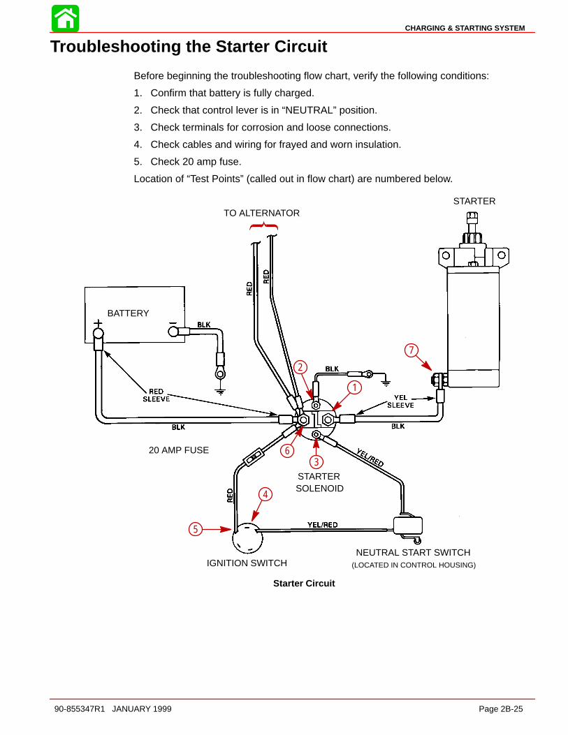
CHARGING & STARTING SYSTEM
90-855347R1 JANUARY 1999 Page 2B-25
Troubleshooting the Starter Circuit
Before beginning the troubleshooting flow chart, verify the following conditions:
1. Confirm that battery is fully charged.
2. Check that control lever is in “NEUTRAL” position.
3. Check terminals for corrosion and loose connections.
4. Check cables and wiring for frayed and worn insulation.
5. Check 20 amp fuse.
Location of “Test Points” (called out in flow chart) are numbered below.
Starter Circuit
STARTER
BATTERY
STARTERSOLENOID
20 AMP FUSE
IGNITION SWITCHNEUTRAL START SWITCH
(LOCATED IN CONTROL HOUSING)
TO ALTERNATOR
7
1
2
63
5
4
1
2
3
4
5
6
7
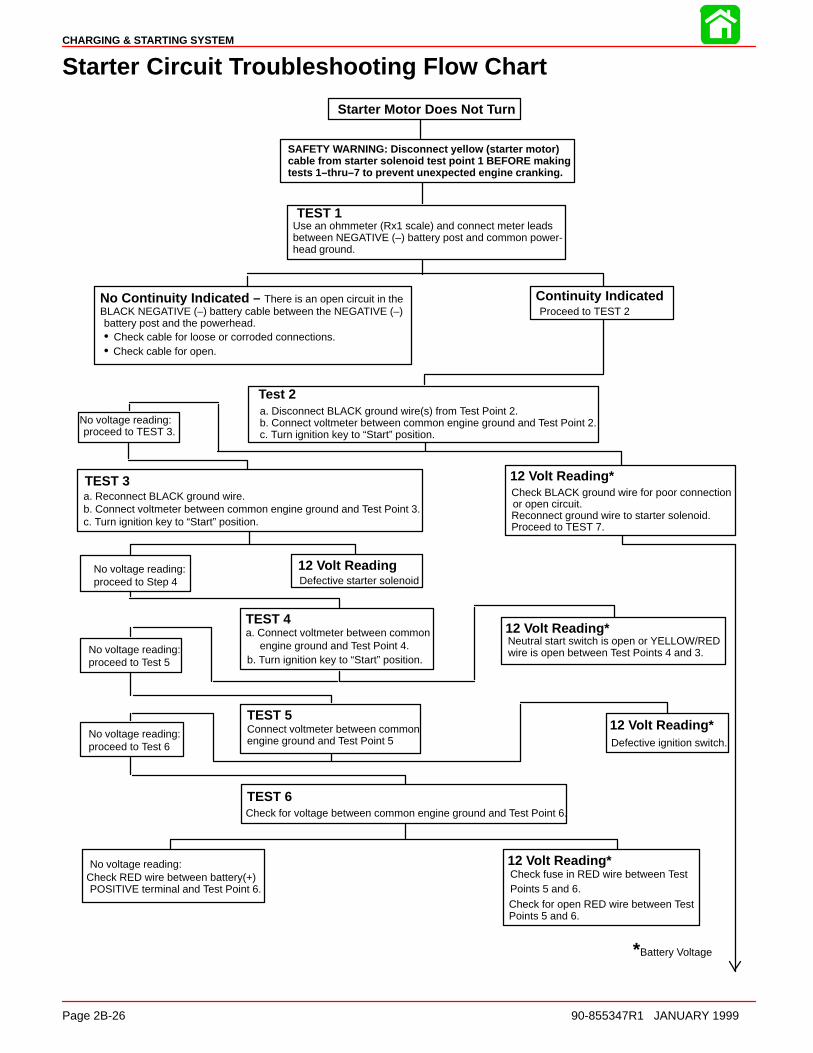
CHARGING & STARTING SYSTEM
Page 2B-26 90-855347R1 JANUARY 1999
Starter Circuit Troubleshooting Flow Chart
Starter Motor Does Not Turn
SAFETY WARNING: Disconnect yellow (starter motor)cable from starter solenoid test point 1 BEFORE makingtests 1–thru–7 to prevent unexpected engine cranking.
TEST 1Use an ohmmeter (Rx1 scale) and connect meter leadsbetween NEGATIVE (–) battery post and common power-head ground.
No Continuity Indicated – There is an open circuit in the BLACK NEGATIVE (–) battery cable between the NEGATIVE (–) battery post and the powerhead.• Check cable for loose or corroded connections.• Check cable for open.
Continuity IndicatedProceed to TEST 2
Test 2a. Disconnect BLACK ground wire(s) from Test Point 2. b. Connect voltmeter between common engine ground and Test Point 2.c. Turn ignition key to “Start” position.
No voltage reading:proceed to TEST 3.
TEST 3a. Reconnect BLACK ground wire.b. Connect voltmeter between common engine ground and Test Point 3.c. Turn ignition key to “Start” position.
12 Volt Reading*Check BLACK ground wire for poor connectionor open circuit.Reconnect ground wire to starter solenoid.Proceed to TEST 7.
12 Volt ReadingDefective starter solenoid
TEST 4a. Connect voltmeter between common
engine ground and Test Point 4.b. Turn ignition key to “Start” position.
12 Volt Reading*Neutral start switch is open or YELLOW/REDwire is open between Test Points 4 and 3.
TEST 5Connect voltmeter between commonengine ground and Test Point 5
12 Volt Reading*Defective ignition switch.
TEST 6Check for voltage between common engine ground and Test Point 6.
No voltage reading:Check RED wire between battery(+)POSITIVE terminal and Test Point 6.
12 Volt Reading*Check fuse in RED wire between TestPoints 5 and 6.Check for open RED wire between TestPoints 5 and 6.
*Battery Voltage
No voltage reading:proceed to Step 4
No voltage reading:proceed to Test 5
No voltage reading:proceed to Test 6

CHARGING & STARTING SYSTEM
90-855347R1 JANUARY 1999 Page 2B-27
TEST 7a. Connect voltmeter between common engine and Test Point1.b. Turn ignition key to “Start” position.
No voltage reading:Defective starter solenoid
12 Volt Reading*Should hear solenoid click: proceed to TEST 8
TEST 8a. Reconnect BLACK cable (with YELLOW sleeve) to starter solenoid TestPoint 1.b. Connect voltmeter between common engine ground and Test Point 7.c. Turn ignition key to “Start” position.
No voltage reading:Check BLACK cable (with YELLOWsleeve) for poor connection or open circuit.
12 Volt Reading*If starter motor does not turn, check starter motor.
*Battery Voltage
Starter Removal and Installation
Removal
CAUTIONDisconnect battery leads from battery before removing starter.
1. Disconnect BLACK ground cable from starter.
2. Disconnect BLACK cable (with YELLOW sleeve) from starter.
3. Remove 2 upper bolts and 1 lower bolt securing starter and remove starter.
a
c
52135
b
a
b
c
a - BLACK (with YELLOW sleeve) POSITIVE (+) 12-Volt Cableb - Upper Mounting Boltsc - Lower Mounting Bolt
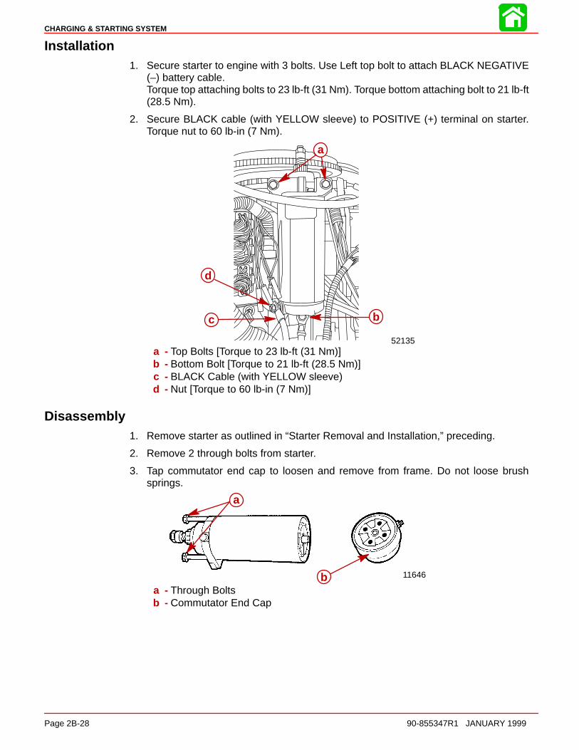
CHARGING & STARTING SYSTEM
Page 2B-28 90-855347R1 JANUARY 1999
Installation1. Secure starter to engine with 3 bolts. Use Left top bolt to attach BLACK NEGATIVE
(–) battery cable.Torque top attaching bolts to 23 lb-ft (31 Nm). Torque bottom attaching bolt to 21 lb-ft(28.5 Nm).
2. Secure BLACK cable (with YELLOW sleeve) to POSITIVE (+) terminal on starter.Torque nut to 60 lb-in (7 Nm).
d
c b
52135
aa
bc
d
a - Top Bolts [Torque to 23 lb-ft (31 Nm)]b - Bottom Bolt [Torque to 21 lb-ft (28.5 Nm)]c - BLACK Cable (with YELLOW sleeve)d - Nut [Torque to 60 lb-in (7 Nm)]
Disassembly1. Remove starter as outlined in “Starter Removal and Installation,” preceding.
2. Remove 2 through bolts from starter.
3. Tap commutator end cap to loosen and remove from frame. Do not loose brushsprings.
11646
a
b
a
ba - Through Boltsb - Commutator End Cap
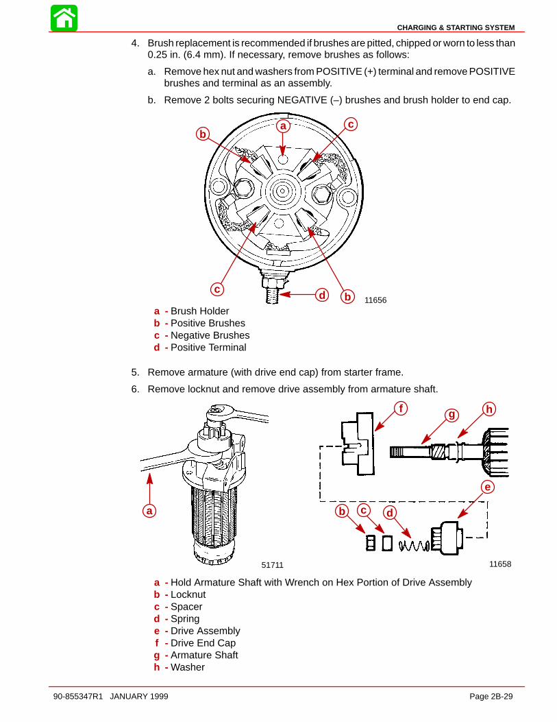
CHARGING & STARTING SYSTEM
90-855347R1 JANUARY 1999 Page 2B-29
4. Brush replacement is recommended if brushes are pitted, chipped or worn to less than0.25 in. (6.4 mm). If necessary, remove brushes as follows:
a. Remove hex nut and washers from POSITIVE (+) terminal and remove POSITIVEbrushes and terminal as an assembly.
b. Remove 2 bolts securing NEGATIVE (–) brushes and brush holder to end cap.
11656
bc
bdc
aab
c
c
bda - Brush Holderb - Positive Brushesc - Negative Brushesd - Positive Terminal
5. Remove armature (with drive end cap) from starter frame.
6. Remove locknut and remove drive assembly from armature shaft.
11658
ef
g
d
cbaa
51711
b c d
e
f g h
a
a - Hold Armature Shaft with Wrench on Hex Portion of Drive Assemblyb - Locknutc - Spacerd - Springe - Drive Assemblyf - Drive End Capg - Armature Shafth - Washer
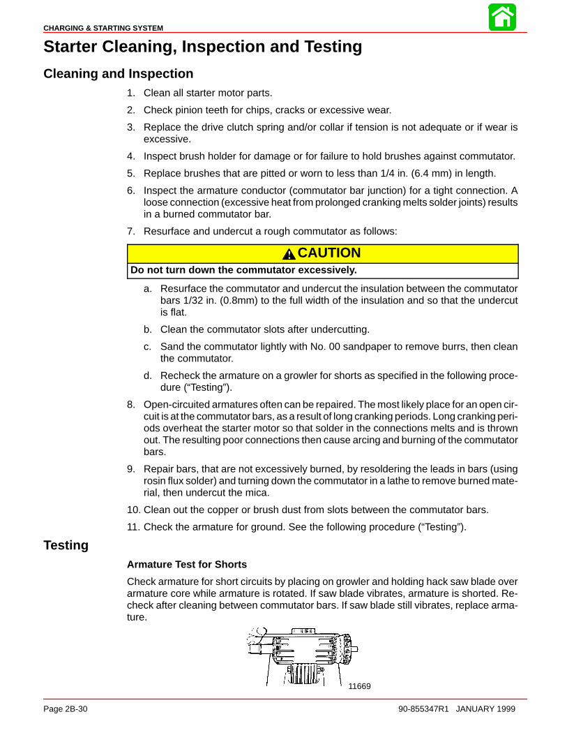
CHARGING & STARTING SYSTEM
Page 2B-30 90-855347R1 JANUARY 1999
Starter Cleaning, Inspection and Testing
Cleaning and Inspection1. Clean all starter motor parts.
2. Check pinion teeth for chips, cracks or excessive wear.
3. Replace the drive clutch spring and/or collar if tension is not adequate or if wear isexcessive.
4. Inspect brush holder for damage or for failure to hold brushes against commutator.
5. Replace brushes that are pitted or worn to less than 1/4 in. (6.4 mm) in length.
6. Inspect the armature conductor (commutator bar junction) for a tight connection. Aloose connection (excessive heat from prolonged cranking melts solder joints) resultsin a burned commutator bar.
7. Resurface and undercut a rough commutator as follows:
CAUTIONDo not turn down the commutator excessively.
a. Resurface the commutator and undercut the insulation between the commutatorbars 1/32 in. (0.8mm) to the full width of the insulation and so that the undercutis flat.
b. Clean the commutator slots after undercutting.
c. Sand the commutator lightly with No. 00 sandpaper to remove burrs, then cleanthe commutator.
d. Recheck the armature on a growler for shorts as specified in the following proce-dure (“Testing”).
8. Open-circuited armatures often can be repaired. The most likely place for an open cir-cuit is at the commutator bars, as a result of long cranking periods. Long cranking peri-ods overheat the starter motor so that solder in the connections melts and is thrownout. The resulting poor connections then cause arcing and burning of the commutatorbars.
9. Repair bars, that are not excessively burned, by resoldering the leads in bars (usingrosin flux solder) and turning down the commutator in a lathe to remove burned mate-rial, then undercut the mica.
10. Clean out the copper or brush dust from slots between the commutator bars.
11. Check the armature for ground. See the following procedure (“Testing”).
TestingArmature Test for Shorts
Check armature for short circuits by placing on growler and holding hack saw blade overarmature core while armature is rotated. If saw blade vibrates, armature is shorted. Re-check after cleaning between commutator bars. If saw blade still vibrates, replace arma-ture.
11669
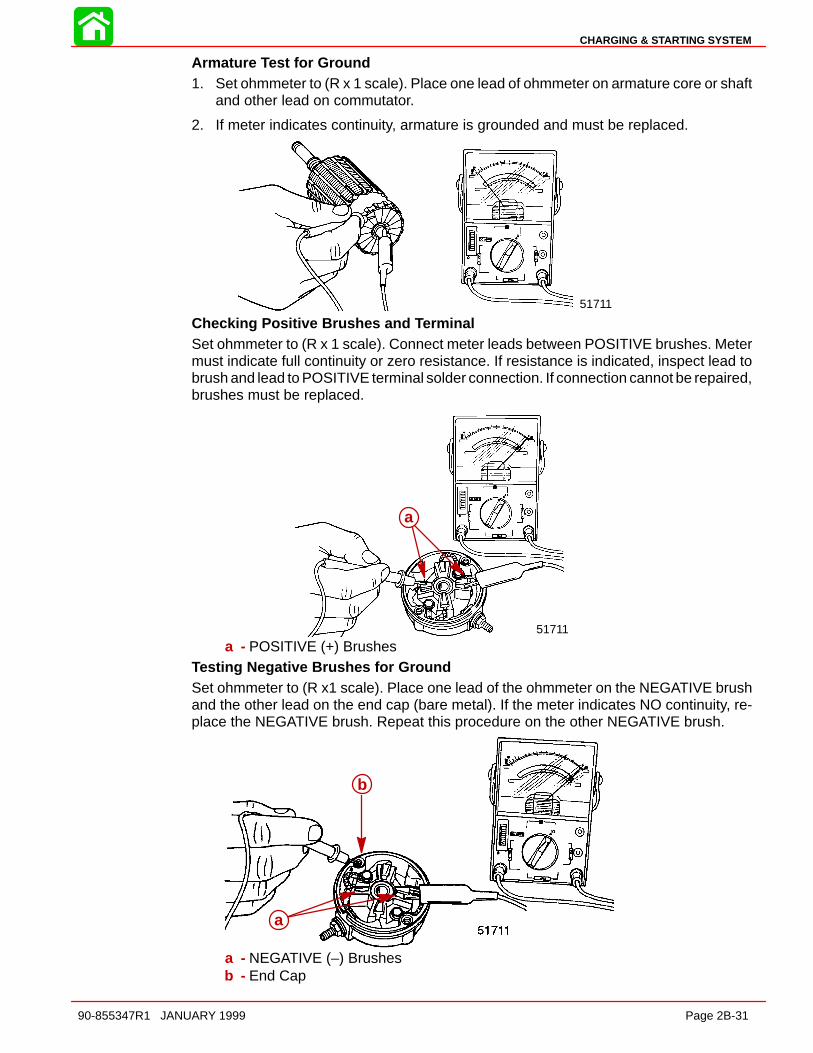
CHARGING & STARTING SYSTEM
90-855347R1 JANUARY 1999 Page 2B-31
Armature Test for Ground1. Set ohmmeter to (R x 1 scale). Place one lead of ohmmeter on armature core or shaft
and other lead on commutator.
2. If meter indicates continuity, armature is grounded and must be replaced.
51711
Checking Positive Brushes and TerminalSet ohmmeter to (R x 1 scale). Connect meter leads between POSITIVE brushes. Metermust indicate full continuity or zero resistance. If resistance is indicated, inspect lead tobrush and lead to POSITIVE terminal solder connection. If connection cannot be repaired,brushes must be replaced.
a
51711
a
a - POSITIVE (+) BrushesTesting Negative Brushes for GroundSet ohmmeter to (R x1 scale). Place one lead of the ohmmeter on the NEGATIVE brushand the other lead on the end cap (bare metal). If the meter indicates NO continuity, re-place the NEGATIVE brush. Repeat this procedure on the other NEGATIVE brush.
aa
b
a - NEGATIVE (–) Brushesb - End Cap
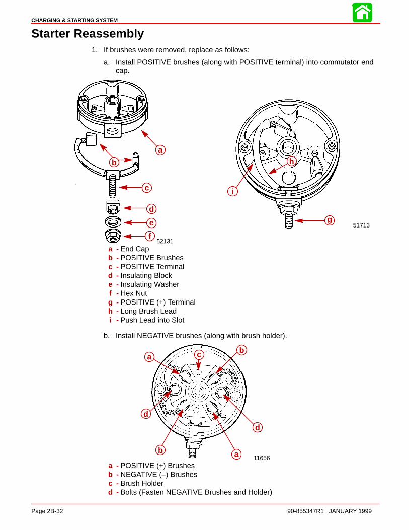
CHARGING & STARTING SYSTEM
Page 2B-32 90-855347R1 JANUARY 1999
Starter Reassembly1. If brushes were removed, replace as follows:
a. Install POSITIVE brushes (along with POSITIVE terminal) into commutator endcap.
52131
a
b
c
d
e
f
c
a
b
51713g
h
i
a
b
c
d
e
f
a - End Capb - POSITIVE Brushesc - POSITIVE Terminald - Insulating Blocke - Insulating Washerf - Hex Nutg - POSITIVE (+) Terminalh - Long Brush Leadi - Push Lead into Slot
b. Install NEGATIVE brushes (along with brush holder).
11656
a cb
d
ab
d
abc
ab
d
d
a - POSITIVE (+) Brushesb - NEGATIVE (–) Brushesc - Brush Holderd - Bolts (Fasten NEGATIVE Brushes and Holder)

CHARGING & STARTING SYSTEM
90-855347R1 JANUARY 1999 Page 2B-33
2. If removed, reinstall parts on armature shaft. Use a new locknut and tighten securelyon end of shaft.
11658
e f gd
cbaa b ce
d
f g
a - Locknutb - Spacerc - Springd - Drive Assemblye - Drive End Capf - Armature Shaftg - Washer
3. Lubricate helix threads on armature shaft with a drop of SAE 10W oil.
4. Lubricate bushing in drive end plate with a drop of SAE 10W oil.
5. Position armature into starter frame.
6. Lubricate bushing (located in commutator end cap) with one drop of SAE 10W oil. DONOT overlubricate.
7. To prevent damage to brushes and springs when installing commutator end cap, it isrecommended that a brush retaining tool be made as shown:
5″
9/16″2-1/6″
1-3/4″
aa
(14.3 mm)(55.1 mm)
(44.5 mm)
(127.0 mm)
a - Bushing (DO NOT overlubricate)
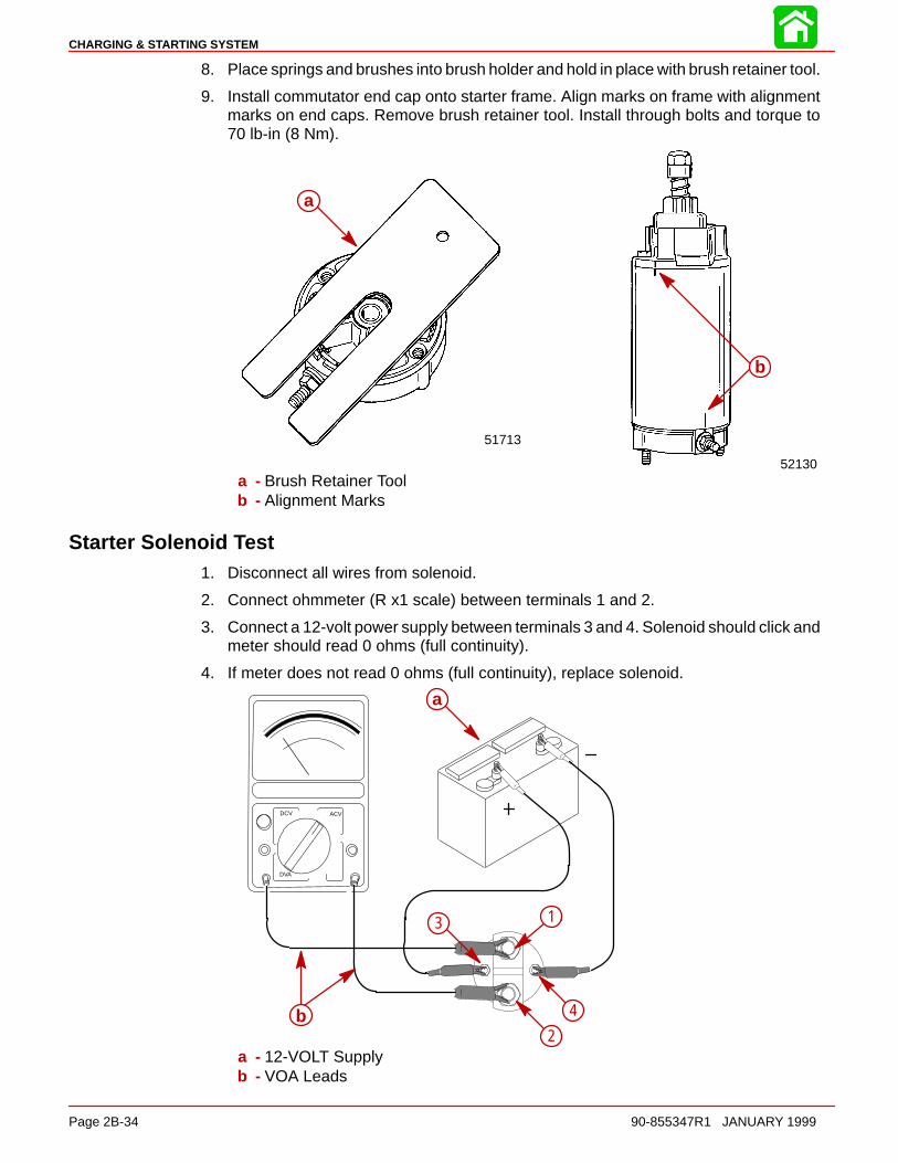
CHARGING & STARTING SYSTEM
Page 2B-34 90-855347R1 JANUARY 1999
8. Place springs and brushes into brush holder and hold in place with brush retainer tool.
9. Install commutator end cap onto starter frame. Align marks on frame with alignmentmarks on end caps. Remove brush retainer tool. Install through bolts and torque to70 lb-in (8 Nm).
52130
a
51713
a
b
a
a - Brush Retainer Toolb - Alignment Marks
Starter Solenoid Test1. Disconnect all wires from solenoid.
2. Connect ohmmeter (R x1 scale) between terminals 1 and 2.
3. Connect a 12-volt power supply between terminals 3 and 4. Solenoid should click andmeter should read 0 ohms (full continuity).
4. If meter does not read 0 ohms (full continuity), replace solenoid.
DCV ACV
DVA
a
b
1
2
3
4
a
b
1
2
3
4
a - 12-VOLT Supplyb - VOA Leads

CHARGING & STARTING SYSTEM
90-855347R1 JANUARY 1999 Page 2B-35
Commander 2000 Key Switch Test
1. Disconnect remote control wiring harness and instrument panel connector.
2. Set ohmmeter on R x 1 scale for the following tests.
3. If meter readings are other than specified in the following tests, verify that switch andnot wiring is faulty. If wiring checks ok, replace switch.
IMPORTANT: Key switch must be positioned to “RUN” or “START” and key pushedin to actuate choke for this test.
KEYPOSITION
OFF
RUN
START
CHOKE*
CONTINUITY SHOULD BE INDICATED AT THE FOLLOWING POINTS:BLK BLK/YEL RED YEL/RED PUR YEL/BLK

2C
TIMING, SYNCHRONIZING & ADJUSTING
90-855347R1 JANUARY 1999 Page 2C-1
ELECTRICALSection 2C – Timing, Synchronizing & Adjusting
Table of Contents
Specifications 2C-1. . . . . . . . . . . . . . . . . . . . . . . . . . . . . . . . Special Tools 2C-2. . . . . . . . . . . . . . . . . . . . . . . . . . . . . . . . Crank Position Sensor 2C-4. . . . . . . . . . . . . . . . . . . . . . . . Throttle Cam Adjustment 2C-5. . . . . . . . . . . . . . . . . . . . . .
Maximum Throttle 2C-5. . . . . . . . . . . . . . . . . . . . . . . . .
Throttle Plate Screw 2C-6. . . . . . . . . . . . . . . . . . . . . . . Throttle Position Sensor (TPS) Adjustment 2C-6. . . . . . Idle Speed 2C-6. . . . . . . . . . . . . . . . . . . . . . . . . . . . . . . . . .
Specifications
FULL THROTTLE RPM RANGE 5000 - 5600
IDLE RPM (IN FORWARD GEAR) 550 ± 25
MAXIMUM TIMING: @ WIDE OPEN Not Adjustable Controlled by ECM
IDLE TIMING Not Adjustable Controlled by ECM
SPARK PLUG TYPELIGHT DUTY
HEAVY DUTYSPARK PLUG GAP
NGK: ZFR5F-11Champion RC12MC4
NGK: PZFR5F-11 (Heavy Duty)*0.040 in. (1.0 mm)
FIRING ORDER 1-2-3-4-5-6
THROTTLE POSITION SENSOR 1(INNER TPS)
@ IDLE@ W.O.T.
3.70 - 4.90 VDC0.30 - 1.80 VDC
THROTTLE POSITION SENSOR 2(OUTER TPS)
@ IDLE@ W.O.T.
0.10 - 1.50 VDC3.20 - 4.90 VDC
*Standard with engine

TIMING, SYNCHRONIZING & ADJUSTING
Page 2C-2 90-855347R1 JANUARY 1999
Special Tools
1. DMT 2000 Digital Tachometer Multi-meter P/N 91-854009A1
2. Digital Diagnostic Tool (DDT) 91-823686A2
3. Software Cartridge 91-822608--4

TIMING, SYNCHRONIZING & ADJUSTING
90-855347R1 JANUARY 1999 Page 2C-3
4. DDT Reference Manual 90-825159-2
5. ECM Harness 84-822560--5
6. Extension Cable [10 ft. (3.05m)] 84-5003A1

TIMING, SYNCHRONIZING & ADJUSTING
Page 2C-4 90-855347R1 JANUARY 1999
Crank Position Sensor
NOTE: Crank Position Sensor is normally not adjustable, but shims are available if sensoris found to be to close to flywheel.
1. Remove flywheel cover.
2. Using a feeler gauge, measure the air gap between the crank position sensor and atooth on the flywheel. Gap should be 0.025 in. - 0.040 in. (0.635 mm - 1.02 mm).
IMPORTANT: Crank Position Sensor must be perpendicular to flywheel tooth.
3. Reinstall flywheel cover.
d
c
56069
a
c
d
be
a - Air Gap [0.025 in - 0.040 in.(0.635 mm - 1.02 mm)]b - Crank Position Sensorc - Flywheel Toothd - Bracket Screw (Drive Tight)e - 0.010 in. (0.254 mm) or 0.020 in. (0.508 mm) Shim if required – refer to parts
manual

TIMING, SYNCHRONIZING & ADJUSTING
90-855347R1 JANUARY 1999 Page 2C-5
Throttle Cam Adjustment
NOTE: Low pressure electric fuel pump is removed for viewing purpose.
1. Loosen roller arm screw allowing roller to move freely.
2. Allow roller to rest on throttle cam. Adjust idle stop screw on throttle arm to align camroller in the pocket of the throttle cam.
3. Tighten roller arm screw to provide clearance of 0.005 in. ± 0.005 in. (0.127 mm ±0.127 mm) between roller and cam.
–
d
a
e 56061
a
b
c
d ea - Roller Arm Screwb - Rollerc - Throttle Camd - Wide Open Throttle Stop Screwe - Idle Stop Screw
Maximum Throttle1. Hold throttle arm against full throttle stop.
2. Adjust full throttle stop screw (located behind electric fuel pump) to allow full throttlevalve opening while maintaining a 0.020 in. (0.508 mm) clearance between arm ofthrottle shaft and stop on attenuator box.
3. Tighten jam nut on full throttle stop screw.
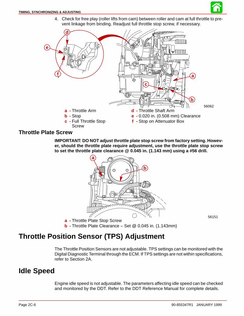
TIMING, SYNCHRONIZING & ADJUSTING
Page 2C-6 90-855347R1 JANUARY 1999
4. Check for free play (roller lifts from cam) between roller and cam at full throttle to pre-vent linkage from binding. Readjust full throttle stop screw, if necessary.
a
b
c
56062
d
e
f a
b
c
d
e
f
a - Throttle Armb - Stopc - Full Throttle Stop
Screw
d - Throttle Shaft Arme - 0.020 in. (0.508 mm) Clearancef - Stop on Attenuator Box
Throttle Plate ScrewIMPORTANT: DO NOT adjust throttle plate stop screw from factory setting. Howev-er, should the throttle plate require adjustment, use the throttle plate stop screwto set the throttle plate clearance @ 0.045 in. (1.143 mm) using a #56 drill.
a
56151
b
a
b
a - Throttle Plate Stop Screwb - Throttle Plate Clearance – Set @ 0.045 in. (1.143mm)
Throttle Position Sensor (TPS) Adjustment
The Throttle Position Sensors are not adjustable. TPS settings can be monitored with theDigital Diagnostic Terminal through the ECM. If TPS settings are not within specifications,refer to Section 2A.
Idle Speed
Engine idle speed is not adjustable. The parameters affecting idle speed can be checkedand monitored by the DDT. Refer to the DDT Reference Manual for complete details.

2D
WIRING DIAGRAMS
90-855347R1 JANUARY 1999 Page 2D-1
ELECTRICALSection 2D – Wiring Diagrams
Table of Contents
Power Trim Wiring Diagram 2D-2. . . . . . . . . . . . . . . . . . . Instrument Wiring Connections 2D-3. . . . . . . . . . . . . . . . . Commander 3000 Classic Panel Remote Control 2D-4. Commander 3000 Panel Remote Control 2D-5. . . . . . . . Instrument/Lanyard Stop Switch Wiring Diagram 2D-6. Oil Level Gauge Wiring Diagram 2D-7. . . . . . . . . . . . . . . Instrument/Lanyard Stop Switch Wiring Diagram(Dual Outboard) 2D-8. . . . . . . . . . . . . . . . . . . . . . . . . . . . . . QSI Gauge Wiring Diagrams 2D-10. . . . . . . . . . . . . . . . .
Tachometer Wiring Diagram 2D-10. . . . . . . . . . . . . . Water Temperature Gauge 2D-11. . . . . . . . . . . . . . . .
Oil Level Gauge Wiring 2D-12. . . . . . . . . . . . . . . . . . . Engine Synchronizer Wiring Diagram 2D-14. . . . . .
Maintenance 2D-15. . . . . . . . . . . . . . . . . . . . . . . . . . . . . . . Multi-Function Gauge 2D-16. . . . . . . . . . . . . . . . . . . . . . .
Dip Switch Setting/Testing 2D-16. . . . . . . . . . . . . . . . Outboard Multi-Function Gauge Setting 2D-17. . . . Warning System Signals 2D-18. . . . . . . . . . . . . . . . . Warning System Operation 2D-19. . . . . . . . . . . . . . .
Panel Mount Remote Control Wiring Installation 2D-221998 135/150 DFI Wiring Diagram 2D-23. . . . . . . . . . . . 1999 135/150 DFI Wiring Diagram 2D-24. . . . . . . . . . . .
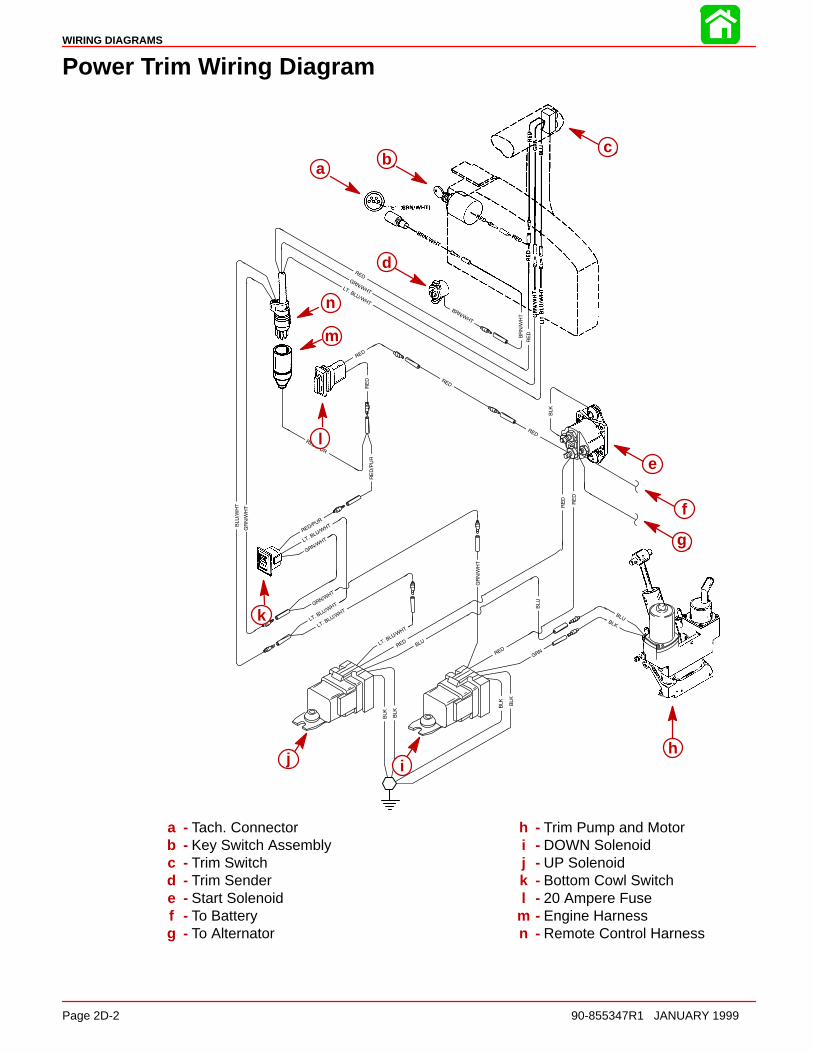
WIRING DIAGRAMS
Page 2D-2 90-855347R1 JANUARY 1999
Power Trim Wiring Diagram
a bc
d
e
f
g
hij
k
l
m
n
a bc
d
e
f
g
hij
k
l
m
n
a - Tach. Connectorb - Key Switch Assemblyc - Trim Switchd - Trim Sendere - Start Solenoidf - To Batteryg - To Alternator
h - Trim Pump and Motori - DOWN Solenoidj - UP Solenoidk - Bottom Cowl Switchl - 20 Ampere Fuse
m - Engine Harnessn - Remote Control Harness
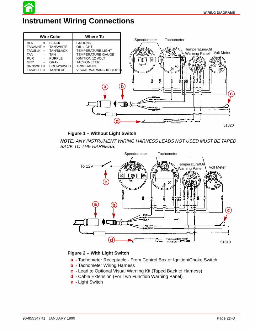
WIRING DIAGRAMS
90-855347R1 JANUARY 1999 Page 2D-3
Instrument Wiring Connections
Speedometer Tachometer
Temperature/Oil Warning Panel Volt Meter
TAN/WHTTAN/BLK
51820
a b
d
c
BLK = BLACK GROUNDTAN/WHT = TAN/WHITE OIL LIGHTTAN/BLK = TAN/BLACK TEMPERATURE LIGHTTAN = TAN TEMPERATURE GAUGEPUR = PURPLE IGNITION 12 VOLTGRY = GRAY TACHOMETERBRN/WHT = BROWN/WHITE TRIM GAUGETAN/BLU = TAN/BLUE VISUAL WARNING KIT (OPT.)
Wire Color Where To
a bc
d
Figure 1 – Without Light Switch
NOTE: ANY INSTRUMENT WIRING HARNESS LEADS NOT USED MUST BE TAPEDBACK TO THE HARNESS.
TAN/WHTTAN/BLK
Speedometer Tachometer
Temperature/Oil Warning Panel Volt Meter
51819
To 12V
e
a b
d
ca b
c
d
e
Figure 2 – With Light Switcha - Tachometer Receptacle - From Control Box or Ignition/Choke Switchb - Tachometer Wiring Harnessc - Lead to Optional Visual Warning Kit (Taped Back to Harness)d - Cable Extension (For Two Function Warning Panel)e - Light Switch
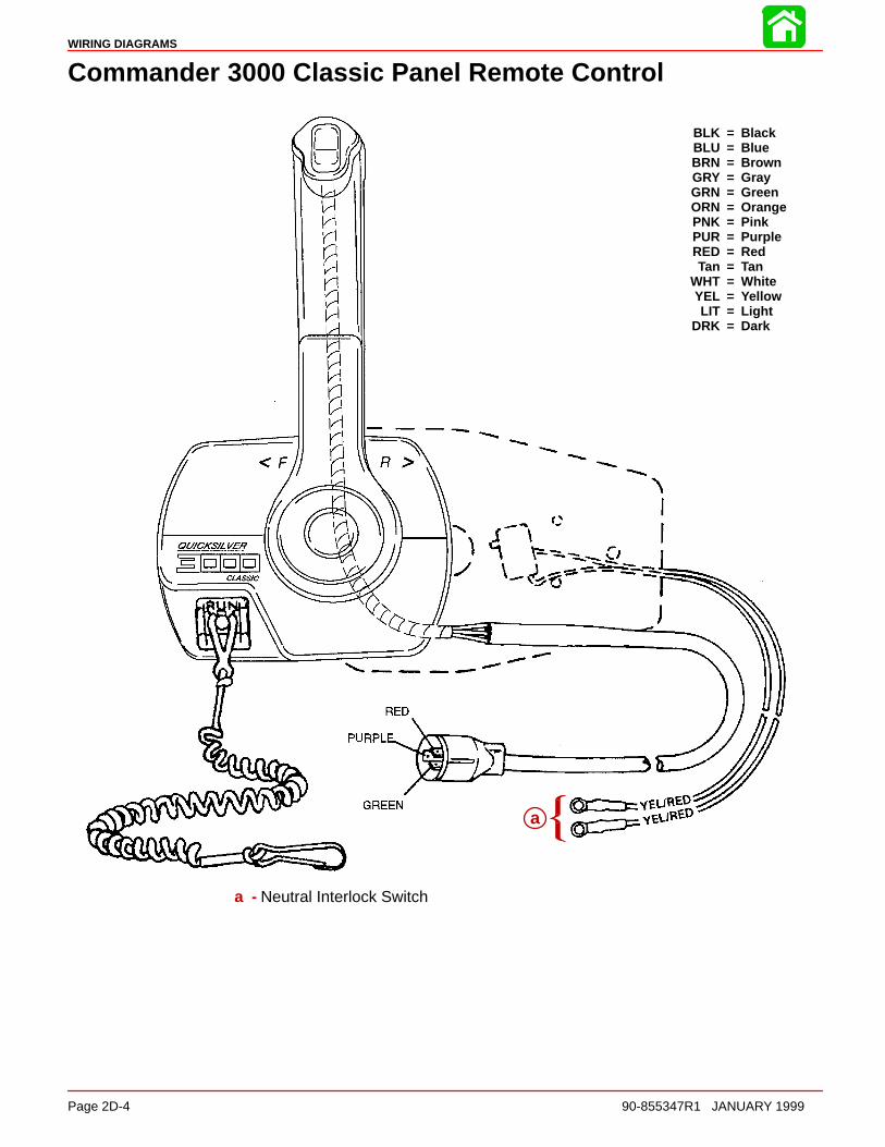
WIRING DIAGRAMS
Page 2D-4 90-855347R1 JANUARY 1999
Commander 3000 Classic Panel Remote Control
BLK = BlackBLU = BlueBRN = BrownGRY = GrayGRN = GreenORN = OrangePNK = PinkPUR = PurpleRED = RedTan = Tan
WHT = WhiteYEL = YellowLIT = Light
DRK = Dark
a
a - Neutral Interlock Switch
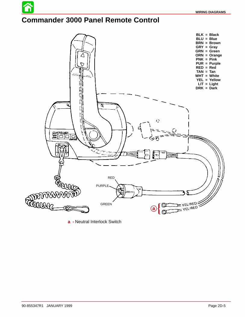
WIRING DIAGRAMS
90-855347R1 JANUARY 1999 Page 2D-5
Commander 3000 Panel Remote Control
RED
PURPLE
GREEN
BLK = BlackBLU = BlueBRN = BrownGRY = GrayGRN = GreenORN = OrangePNK = PinkPUR = PurpleRED = RedTAN = Tan
WHT = WhiteYEL = YellowLIT = Light
DRK = Dark
aa
a - Neutral Interlock Switch
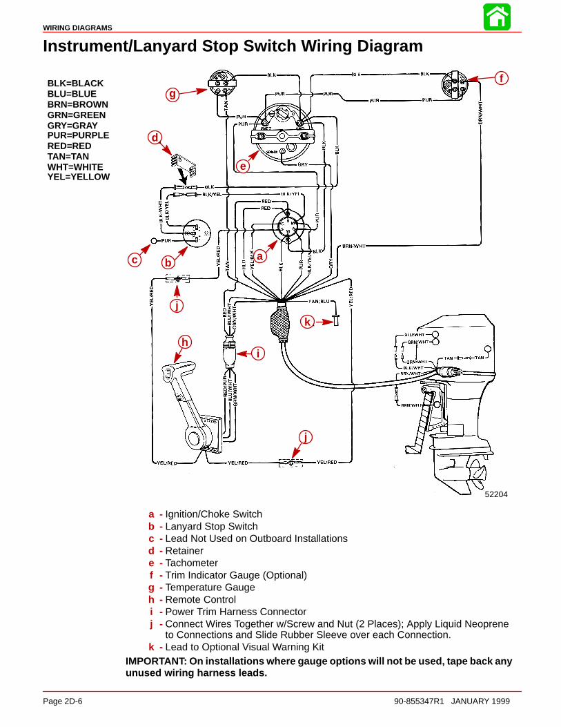
WIRING DIAGRAMS
Page 2D-6 90-855347R1 JANUARY 1999
Instrument/Lanyard Stop Switch Wiring Diagram
BLK=BLACKBLU=BLUEBRN=BROWNGRN=GREENGRY=GRAYPUR=PURPLERED=REDTAN=TANWHT=WHITEYEL=YELLOW
52204
d
e
abc
j
i
k
j
h
fg
abc
d
e
hi
j
k
j
a - Ignition/Choke Switchb - Lanyard Stop Switchc - Lead Not Used on Outboard Installationsd - Retainere - Tachometerf - Trim Indicator Gauge (Optional)g - Temperature Gaugeh - Remote Controli - Power Trim Harness Connectorj - Connect Wires Together w/Screw and Nut (2 Places); Apply Liquid Neoprene
to Connections and Slide Rubber Sleeve over each Connection.k - Lead to Optional Visual Warning Kit
IMPORTANT: On installations where gauge options will not be used, tape back anyunused wiring harness leads.

WIRING DIAGRAMS
90-855347R1 JANUARY 1999 Page 2D-7
Oil Level Gauge Wiring Diagram
a
b
c
i
o
m
n
j
kl
h
g
f
p
qr
s
t
e
d
a
b
c
d
e
f
g
h
i
j
klm
n
o
p
qr
s
t
a - To 12 Volt Sourceb - PURPLE Wire (Connect to Trim Indicator Gauge “I” [or POSITIVE (+) 12 Volt
Source that is Turned “ON” and “OFF” with Ignition Switch])c - Oil Level Gauged - BLACK Wire (Connects to NEGATIVE Ground)e - To Groundf - BLACK Wire (From Gauge to Oil Clip Connector)g - LIGHT BLUE Sender Lead to Gaugeh - Wiring Harness (LT. BLU. and BLACK)i - Screw (10-16 x 5/8 in.)j - Springk - Oil Clip Connectorl - Adaptor Housing
m - Screw (10-16 x 1/4 in.)n - Springo - Screw (10-16 x 5/8 in.)p - BLACK Wireq - Oil Level Sender Unitr - Oil Pick-Up Tubes - WHITE Lead (from Oil Level Sender)t - Screw (10-16 x 5/8 in.)
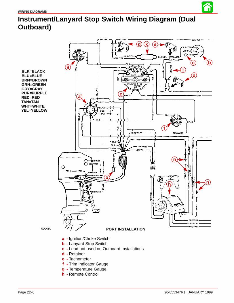
WIRING DIAGRAMS
Page 2D-8 90-855347R1 JANUARY 1999
Instrument/Lanyard Stop Switch Wiring Diagram (DualOutboard)
BLK=BLACKBLU=BLUEBRN=BROWNGRN=GREENGRY=GRAYPUR=PURPLERED=REDTAN=TANWHT=WHITEYEL=YELLOW
52205
g
ae
d k d
bc
ld
f
n
nh
o
BATT GND
SENDER
PORT INSTALLATION
a
g
d k d
c b
ld
e
f
n
nh
o
a - Ignition/Choke Switchb - Lanyard Stop Switchc - Lead not used on Outboard Installationsd - Retainere - Tachometerf - Trim Indicator Gaugeg - Temperature Gaugeh - Remote Control

WIRING DIAGRAMS
90-855347R1 JANUARY 1999 Page 2D-9
IMPORTANT: On installations where gauge options will not be used, tape back andisolate unused wiring harness leads.
52206
i
g
ae
jf
m
o
STARBOARD INSTALLATION
BATT GND
SENDER
g
i
jf
m
o
ae
i - Synchronizer Gaugej - Synchronizer Modulek - Lanyard Switch (Isolation) Diodel - Y Harness
m - Power Trim Harness Connectorn - Connect Wires together with Screw and Nut (4 Places); Apply Liquid Neo-
prene to Connections and slide Rubber Sleeve over each Connection.o - Lead to Visual Warning Kit
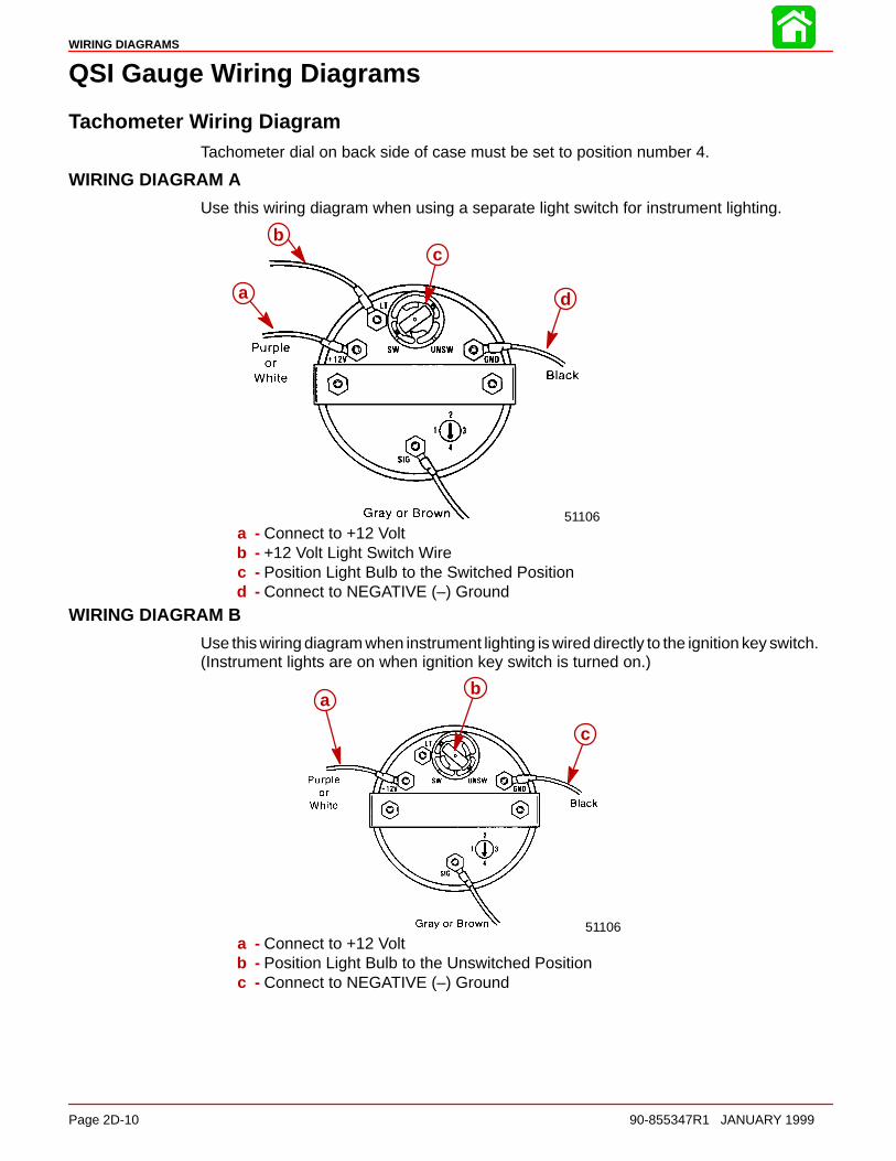
WIRING DIAGRAMS
Page 2D-10 90-855347R1 JANUARY 1999
QSI Gauge Wiring Diagrams
Tachometer Wiring DiagramTachometer dial on back side of case must be set to position number 4.
WIRING DIAGRAM A
Use this wiring diagram when using a separate light switch for instrument lighting.
51106
a
c
d
b
a - Connect to +12 Voltb - +12 Volt Light Switch Wirec - Position Light Bulb to the Switched Positiond - Connect to NEGATIVE (–) Ground
WIRING DIAGRAM B
Use this wiring diagram when instrument lighting is wired directly to the ignition key switch.(Instrument lights are on when ignition key switch is turned on.)
51106
ab
c
a - Connect to +12 Voltb - Position Light Bulb to the Unswitched Positionc - Connect to NEGATIVE (–) Ground
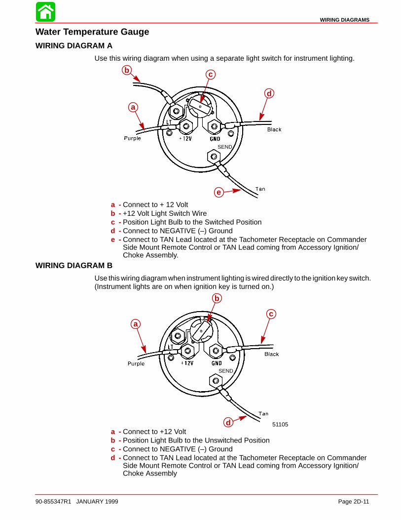
WIRING DIAGRAMS
90-855347R1 JANUARY 1999 Page 2D-11
Water Temperature GaugeWIRING DIAGRAM A
Use this wiring diagram when using a separate light switch for instrument lighting.
SEND
a
b c
d
e
a - Connect to + 12 Voltb - +12 Volt Light Switch Wirec - Position Light Bulb to the Switched Positiond - Connect to NEGATIVE (–) Grounde - Connect to TAN Lead located at the Tachometer Receptacle on Commander
Side Mount Remote Control or TAN Lead coming from Accessory Ignition/Choke Assembly.
WIRING DIAGRAM B
Use this wiring diagram when instrument lighting is wired directly to the ignition key switch.(Instrument lights are on when ignition key is turned on.)
51105
SEND
a
b
c
da - Connect to +12 Voltb - Position Light Bulb to the Unswitched Positionc - Connect to NEGATIVE (–) Groundd - Connect to TAN Lead located at the Tachometer Receptacle on Commander
Side Mount Remote Control or TAN Lead coming from Accessory Ignition/Choke Assembly
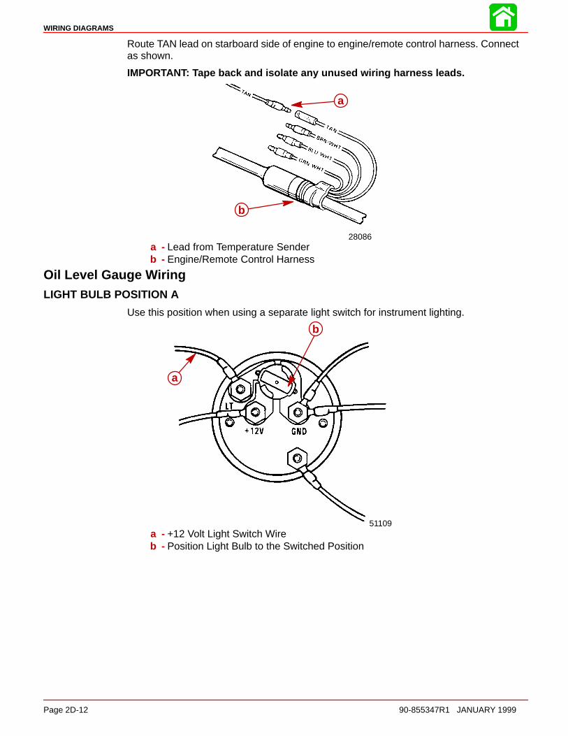
WIRING DIAGRAMS
Page 2D-12 90-855347R1 JANUARY 1999
Route TAN lead on starboard side of engine to engine/remote control harness. Connectas shown.
IMPORTANT: Tape back and isolate any unused wiring harness leads.
28086
a
b
a - Lead from Temperature Senderb - Engine/Remote Control Harness
Oil Level Gauge WiringLIGHT BULB POSITION A
Use this position when using a separate light switch for instrument lighting.
51109
a
b
a - +12 Volt Light Switch Wireb - Position Light Bulb to the Switched Position
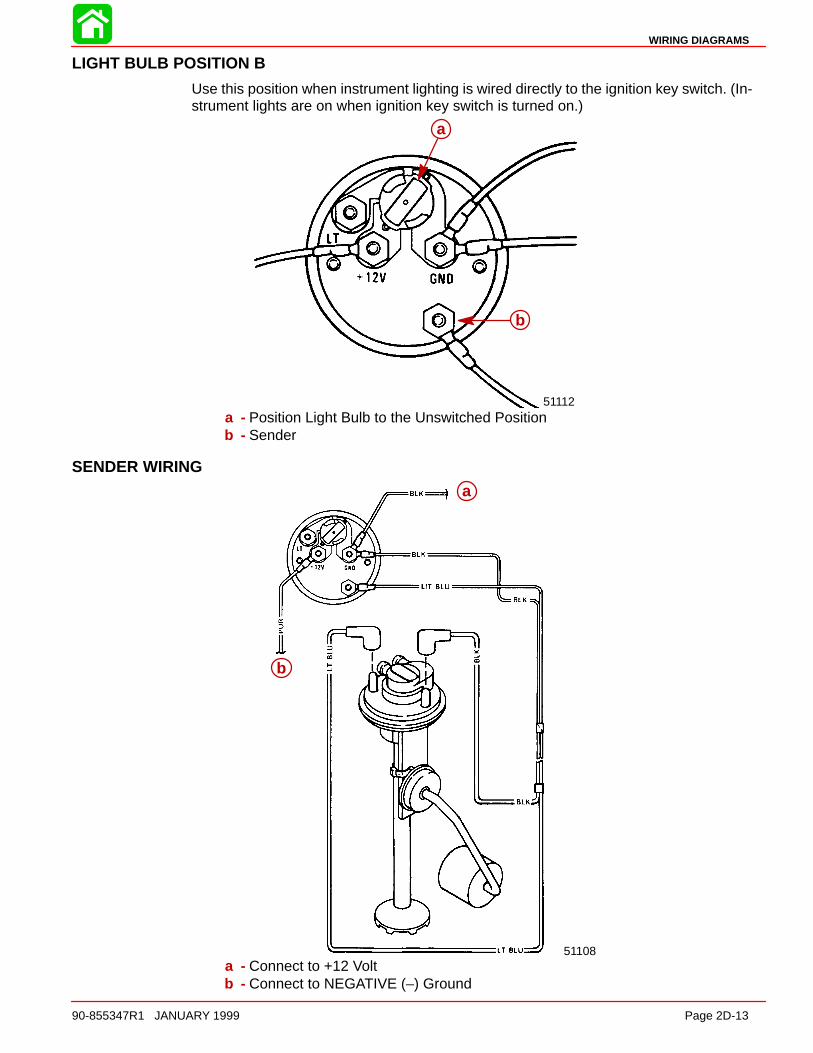
WIRING DIAGRAMS
90-855347R1 JANUARY 1999 Page 2D-13
LIGHT BULB POSITION B
Use this position when instrument lighting is wired directly to the ignition key switch. (In-strument lights are on when ignition key switch is turned on.)
51112
a
b
a - Position Light Bulb to the Unswitched Positionb - Sender
SENDER WIRING
51108
a
b
a
b
a - Connect to +12 Voltb - Connect to NEGATIVE (–) Ground
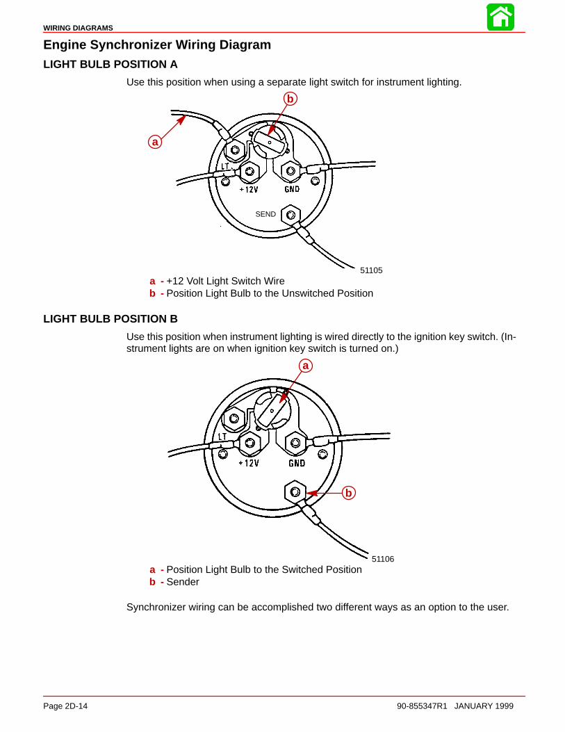
WIRING DIAGRAMS
Page 2D-14 90-855347R1 JANUARY 1999
Engine Synchronizer Wiring DiagramLIGHT BULB POSITION A
Use this position when using a separate light switch for instrument lighting.
SEND
51105
a
b
a - +12 Volt Light Switch Wireb - Position Light Bulb to the Unswitched Position
LIGHT BULB POSITION B
Use this position when instrument lighting is wired directly to the ignition key switch. (In-strument lights are on when ignition key switch is turned on.)
51106
a
b
a - Position Light Bulb to the Switched Positionb - Sender
Synchronizer wiring can be accomplished two different ways as an option to the user.
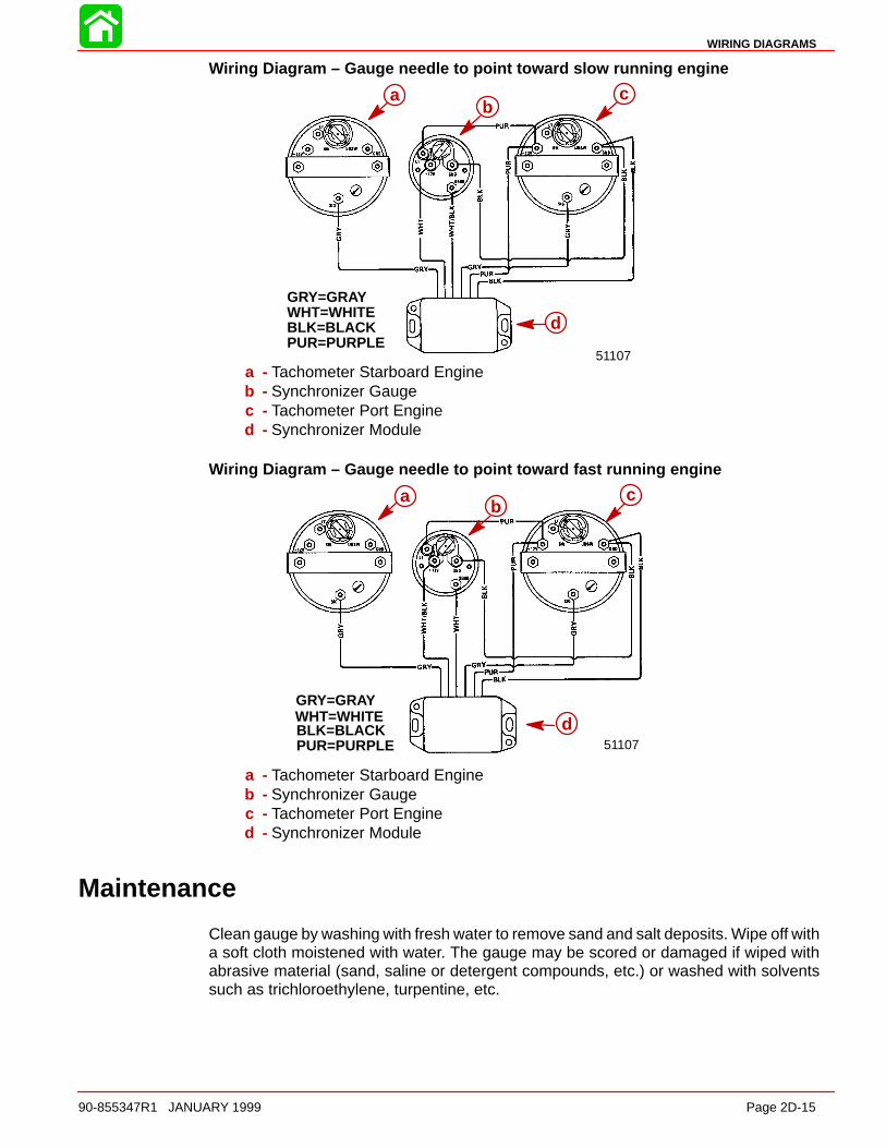
WIRING DIAGRAMS
90-855347R1 JANUARY 1999 Page 2D-15
Wiring Diagram – Gauge needle to point toward slow running engine
GRY=GRAYWHT=WHITEBLK=BLACKPUR=PURPLE
51107
bc
d
ab
c
d
a - Tachometer Starboard Engineb - Synchronizer Gaugec - Tachometer Port Engined - Synchronizer Module
Wiring Diagram – Gauge needle to point toward fast running engine
GRY=GRAYWHT=WHITEBLK=BLACKPUR=PURPLE
bc
d51107
ab
c
d
a - Tachometer Starboard Engineb - Synchronizer Gaugec - Tachometer Port Engined - Synchronizer Module
Maintenance
Clean gauge by washing with fresh water to remove sand and salt deposits. Wipe off witha soft cloth moistened with water. The gauge may be scored or damaged if wiped withabrasive material (sand, saline or detergent compounds, etc.) or washed with solventssuch as trichloroethylene, turpentine, etc.

WIRING DIAGRAMS
Page 2D-16 90-855347R1 JANUARY 1999
Multi-Function Gauge
Dip Switch Setting/TestingNOTE: The multi-function gauge “Dip Switch” must be set on the back of gauge prior tooperation. Turn the ignition switch to the “OFF” position before setting dip switch. Thegauge will reset to selected settings when the ignition is turned “On”.
IMPORTANT: Test the gauge and related wiring BEFORE making final “Dip Switch”settings and BEFORE securing the gauge to dashboard of boat.
1. With the ignition switch in the “Off” position, set the multi-function gauge “Dip Switch”in (test) position as shown. (BLACK dot indicates switch position).
a
b
52095Open
1 2 3 4
a
a
b
a - “Dip Switch” (shown in test position)b - Black Dot - Switch in “Open” Position
2. Turn ignition switch to the “Run” position. The multi-function gauge now is in the dis-play test mode. The gauge Temp, Batt, Oil, and Fuel red warning lights should be alter-nately flashing “On” and “Off”; the BLACK L.C.D. bar graphs should be cycling. (Thisindicates that all gauge functions are operational).
3. Turn ignition switch to the “Off” position. Reset the gauge “Dip Switch” to the correctoperating position for the outboard application.
b
aa
b
a - Gauge Lights (Red)b - Gauge L.C.D. Bar Graph (Black)
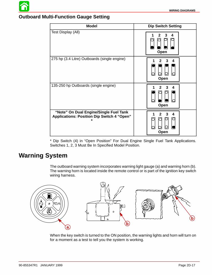
WIRING DIAGRAMS
90-855347R1 JANUARY 1999 Page 2D-17
Outboard Multi-Function Gauge Setting
Model Dip Switch Setting
Test Display (All)
Open
1 2 3 4
275 hp (3.4 Litre) Outboards (single engine)
Open
1 2 3 4
135-250 hp Outboards (single engine)
Open
1 2 3 4
“Note” On Dual Engine/Single Fuel TankApplications: Position Dip Switch 4 “Open”
*
Open
1 2 3 4
* Dip Switch (4) in “Open Position” For Dual Engine Single Fuel Tank Applications.Switches 1, 2, 3 Must Be In Specified Model Position.
Warning System
The outboard warning system incorporates warning light gauge (a) and warning horn (b).The warning horn is located inside the remote control or is part of the ignition key switchwiring harness.
ab
b
ab
b
When the key switch is turned to the ON position, the warning lights and horn will turn onfor a moment as a test to tell you the system is working.
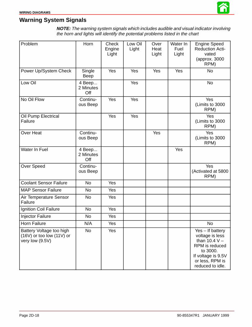
WIRING DIAGRAMS
Page 2D-18 90-855347R1 JANUARY 1999
Warning System SignalsNOTE: The warning system signals which includes audible and visual indicator involvingthe horn and lights will identify the potential problems listed in the chart
Problem Horn CheckEngineLight
Low OilLight
OverHeatLight
Water InFuelLight
Engine Speed Reduction Acti-
vated(approx. 3000
RPM)
Power Up/System Check SingleBeep
Yes Yes Yes Yes No
Low Oil 4 Beep...2 Minutes
Off
Yes No
No Oil Flow Continu-ous Beep
Yes Yes Yes (Limits to 3000
RPM)
Oil Pump Electrical Failure
Yes Yes Yes(Limits to 3000
RPM)
Over Heat Continu-ous Beep
Yes Yes (Limits to 3000
RPM)
Water In Fuel 4 Beep...2 Minutes
Off
Yes
Over Speed Continu-ous Beep
Yes (Activated at 5800
RPM)
Coolant Sensor Failure No Yes
MAP Sensor Failure No Yes
Air Temperature SensorFailure
No Yes
Ignition Coil Failure No Yes
Injector Failure No Yes
Horn Failure N/A Yes No
Battery Voltage too high(16V) or too low (11V) orvery low (9.5V)
No Yes Yes – If batteryvoltage is lessthan 10.4 V –
RPM is reducedto 3000.
If voltage is 9.5Vor less, RPM isreduced to idle.
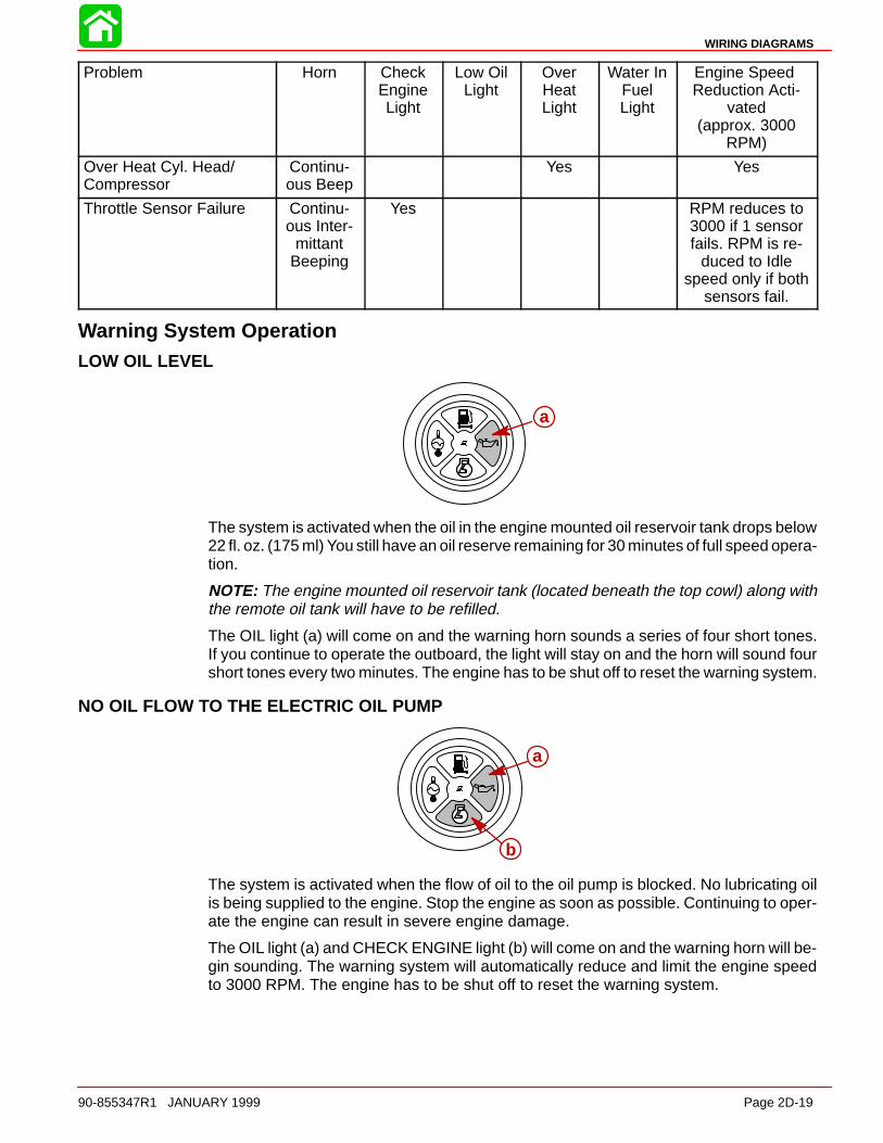
WIRING DIAGRAMS
90-855347R1 JANUARY 1999 Page 2D-19
Problem Horn CheckEngineLight
Low OilLight
OverHeatLight
Water InFuelLight
Engine Speed Reduction Acti-
vated(approx. 3000
RPM)
Over Heat Cyl. Head/Compressor
Continu-ous Beep
Yes Yes
Throttle Sensor Failure Continu-ous Inter-
mittantBeeping
Yes RPM reduces to3000 if 1 sensorfails. RPM is re-
duced to Idlespeed only if both
sensors fail.
Warning System OperationLOW OIL LEVEL
aa
The system is activated when the oil in the engine mounted oil reservoir tank drops below22 fl. oz. (175 ml) You still have an oil reserve remaining for 30 minutes of full speed opera-tion.
NOTE: The engine mounted oil reservoir tank (located beneath the top cowl) along withthe remote oil tank will have to be refilled.
The OIL light (a) will come on and the warning horn sounds a series of four short tones.If you continue to operate the outboard, the light will stay on and the horn will sound fourshort tones every two minutes. The engine has to be shut off to reset the warning system.
NO OIL FLOW TO THE ELECTRIC OIL PUMP
a
b
a
b
The system is activated when the flow of oil to the oil pump is blocked. No lubricating oilis being supplied to the engine. Stop the engine as soon as possible. Continuing to oper-ate the engine can result in severe engine damage.
The OIL light (a) and CHECK ENGINE light (b) will come on and the warning horn will be-gin sounding. The warning system will automatically reduce and limit the engine speedto 3000 RPM. The engine has to be shut off to reset the warning system.

WIRING DIAGRAMS
Page 2D-20 90-855347R1 JANUARY 1999
ENGINE OVERHEAT
aa
The system is activated when the engine temperature is too hot.
The TEMP light (a) will come on and the warning horn begins sounding. The warning sys-tem will automatically limit the engine speed to 3000 RPM. After the engine has cooled,shift the outboard into neutral to reset the overheat circuit.
IGNITION COIL, SENSOR, OR INJECTOR NOT FUNCTIONING
aa
The system is activated if an ignition coil, sensor or injector is not functioning correctly.
The CHECK ENGINE light (a) will turn on.
THROTTLE SENSOR NOT FUNCTIONING
aa
The system is activated if the throttle sensors are not functioning correctly.
The CHECK ENGINE light (a) will turn on and the warning horn will begin sounding.
WATER SEPARATING FUEL FILTER IS FULL OF WATER
a
The water level detection warning is activated when water in the water separating fuel fil-ter reaches the full level. The water can be removed from the filter.
The WATER DETECTION light (a) will come on and the warning horn will begin soundinga series of four beeps. If you continue to operate the outboard, the light will stay on andthe horn will sound every two minutes.
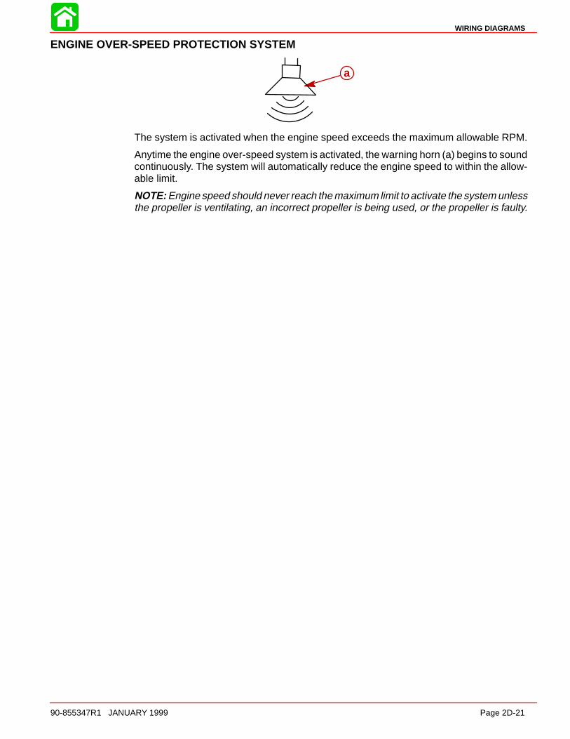
WIRING DIAGRAMS
90-855347R1 JANUARY 1999 Page 2D-21
ENGINE OVER-SPEED PROTECTION SYSTEM
aa
The system is activated when the engine speed exceeds the maximum allowable RPM.
Anytime the engine over-speed system is activated, the warning horn (a) begins to soundcontinuously. The system will automatically reduce the engine speed to within the allow-able limit.
NOTE: Engine speed should never reach the maximum limit to activate the system unlessthe propeller is ventilating, an incorrect propeller is being used, or the propeller is faulty.
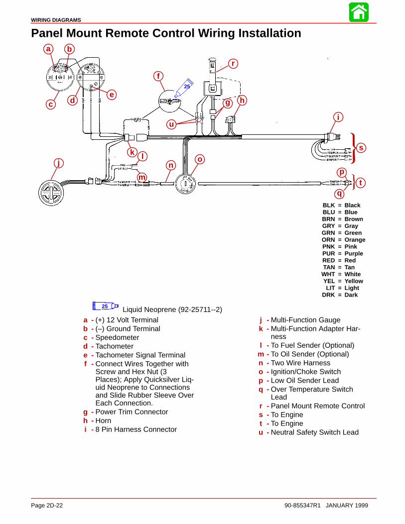
WIRING DIAGRAMS
Page 2D-22 90-855347R1 JANUARY 1999
Panel Mount Remote Control Wiring Installation
BLK = BlackBLU = BlueBRN = BrownGRY = GrayGRN = GreenORN = OrangePNK = PinkPUR = PurpleRED = RedTAN = Tan
WHT = WhiteYEL = YellowLIT = Light
DRK = Dark
a b
c d
f
g h
r
ui
s
tp
q
on
m
lkj
e25
a b
c de
f
g h
i
jk l
m
no
p
q
r
s
t
u
25 Liquid Neoprene (92-25711--2)a - (+) 12 Volt Terminalb - (–) Ground Terminalc - Speedometerd - Tachometere - Tachometer Signal Terminalf - Connect Wires Together with
Screw and Hex Nut (3Places); Apply Quicksilver Liq-uid Neoprene to Connectionsand Slide Rubber Sleeve OverEach Connection.
g - Power Trim Connectorh - Horni - 8 Pin Harness Connector
j - Multi-Function Gaugek - Multi-Function Adapter Har-
nessl - To Fuel Sender (Optional)
m - To Oil Sender (Optional)n - Two Wire Harnesso - Ignition/Choke Switchp - Low Oil Sender Leadq - Over Temperature Switch
Leadr - Panel Mount Remote Controls - To Enginet - To Engineu - Neutral Safety Switch Lead
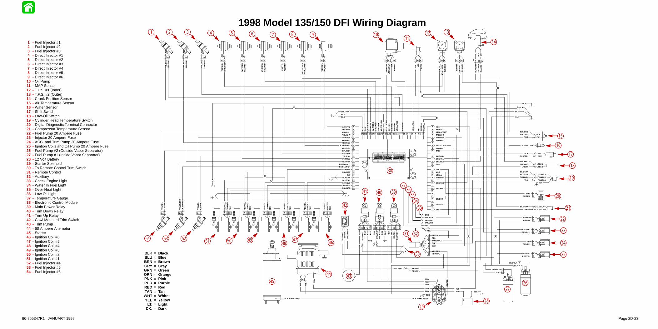
BLK = BlackBLU = BlueBRN = BrownGRY = GrayGRN = GreenORN = OrangePNK = PinkPUR = PurpleRED = RedTAN = Tan
WHT = WhiteYEL = Yellow
LT. = LightDK. = Dark
1998 Model 135/150 DFI Wiring Diagram
RE
D/B
LU
RE
D/B
LU
YE
L
LT.B
LU/B
LK
PN
K/O
RG
LT.B
LU/R
ED
PN
K/B
RN
BR
N/W
HT
BLK
/OR
GW
HT
/DK
.BLU
OR
G/P
NK
OR
G/W
HT
BR
N/P
NK
WH
T/B
RN
BLK
RE
D/Y
EL
PPLBLU/YEL
TAN/BLK
PNK/LT.BLU
TAN/PPLTAN
BLK/GRNBLK/YEL
WHT
LT.BLU
BLK/TAN
GRY/RED
GR
N/R
ED
RE
D/Y
EL
GR
N/O
RG
RE
D/Y
EL
GR
N/Y
EL
RE
D/Y
EL
GR
N/B
LU
RE
D/Y
EL
GR
N/P
PL
RE
D/Y
EL
GR
N/B
RN
WH
T/B
RN
BR
N/W
HT
WH
T/R
ED
RE
D/W
HT
WH
T/O
RG
OR
G/W
HT
WH
T/Y
EL
YE
L/W
HT
WH
T/D
K.B
LUD
K.B
LU/W
HT
WH
T/P
PL
PP
L/W
HT
GRN/PPLPPL/WHT
RED/WHTPNK/RED
DK.BLU/WHT
WHT/PPLPPL/PNK
WHT/YELYEL/PNK
WHT/RED
DK.BLU/PNK
GRN/YELGRN/RED
BLK
BLK/TAN
GRN/BLUGRN/ORG
PNK/PPLYEL/WHTPNK/YEL
RED/PNKPNK/DK.BLU
BLK/TAN
GRN/BRN
OR
G/P
NK
PN
K/O
RG
RE
D/P
NK
PN
K/R
ED
BR
N/P
NK
PN
K/B
RN
PP
L/Y
EL
LT.B
LU/G
RN
WH
T/O
RG
BLK
LT.B
LU/G
RN
LT.B
LU/B
LK BLK
RE
D/Y
EL
PP
L/Y
EL
LT.B
LU/R
ED
BLK
/OR
G
BLK
/GR
NLT
.BLU
/WH
T
BLU
/YE
L
PP
L/Y
EL
YE
LB
LK/O
RG
LT.BLU/WHT
TAN/WHTTAN/LT.BLU
BLK/REDGRY
TAN/GRN
YEL/PPL
DK.BLU
BLK
/GR
N
GR
Y/R
ED
BLU
/YE
L
ORG
TAN/PPL
TANBLK/ORG
PNK/LT.BLU
TAN/BLKTAN/WHT
ORG
TANBLK
TAN/BLKTAN/BLK
TAN/BLU
BLK
TAN
DN
UP
BLK
DDT
BRNBLK
BLK
BLK
BLK
BLK
BLK
PPLPPL
BLK/GRNTAN/GRN
TAN
BLK/GRN
LT.BLU
LT.BLUBLK/ORG
LT.BLU
1
23
456
78
910
111213
141516
1718
192021
2223
24
1
23
456
78
910
111213
141516
1718
192021
2223
242526
272829
3031
32
12345678109 11121314151618171920212223241 2345678 109 11121314151617181920222324252627282921303132
21 345678109 1112131415161817192021222324
123456789101112131415161718192021222324
BLK
DK
.BLU
/PN
K
PN
K/D
K.B
LU
YE
L/P
NK
PN
K/Y
EL
PP
L/P
NK
PN
K/P
PL
B A B A B A
B A B A B A
B A B A B A B A B A B A
A B CA B CA B CA B CA B CA B C
C DBA B AC B AC B AC A B C
BLK
PP
L
GR
Y
BLK/ORG
BLK/ORG
BLKBLK
BLKBLK/RED
TAN/BLK
TAN/BLK
BLK/GRNBRN
1
234
56
78
BLK/YEL
PPLTAN/LT.BLUBLK
GRY
YEL/REDRED/PPL
DK.BLUWHT
AB
86 878530 87a
GR
N/W
HT
GR
N
RE
DB
LK BLK
86 878530 87a
PP
L
RE
D
RE
D/W
HT
YE
L/P
PL
RED
RED/WHT
RED/WHT
RED/BLK
RED/BLU
RED/WHTRED/YEL
RED/PPL
BA
BA
B
A
BA
86 878530 87a
LT.B
LU/W
HT
BLU
RE
DB
LK
BLK
RED
A B C
RE
D
PP
L
REDRED
BLK
YE
L/R
ED
RED
RED
RED
BARED/BLK
BLK
BLK W/YEL ENDSBLK W/YEL ENDS
RED
RED/PPLRED/PPL
RED/PPL
RE
D/P
PL
LT.B
LU/W
HT
GR
N/W
HT
BLK
BLK
BLK
BLK
BLK
BLK/TAN
BLK
RE
D
BARED/BLK
BLK
1 - Fuel Injector #12 - Fuel Injector #23 - Fuel Injector #34 - Direct Injector #15 - Direct Injector #26 - Direct Injector #37 - Direct Injector #48 - Direct Injector #59 - Direct Injector #610 - Oil Pump11 - MAP Sensor12 - T.P.S. #1 (Inner)13 - T.P.S. #2 (Outer)14 - Crank Position Sensor15 - Air Temperature Sensor16 - Water Sensor17 - Shift Switch18 - Low-Oil Switch19 - Cylinder Head Temperature Switch20 - Digital Diagnostic Terminal Connector21 - Compressor Temperature Sensor22 - Fuel Pump 20 Ampere Fuse23 - Injector 20 Ampere Fuse24 - ACC. and Trim Pump 20 Ampere Fuse25 - Ignition Coils and Oil Pump 20 Ampere Fuse26 - Fuel Pump #2 (Outside Vapor Separator)27 - Fuel Pump #1 (Inside Vapor Separator)28 - 12 Volt Battery29 - Starter Solenoid30 - To Remote Control Trim Switch31 - Remote Control32 - Auxiliary33 - Check Engine Light34 - Water In Fuel Light35 - Over-Heat Light36 - Low Oil Light37 - Temperature Gauge38 - Electronic Control Module39 - Main Power Relay40 - Trim Down Relay41 - Trim Up Relay42 - Cowl Mounted Trim Switch43 - Trim Pump44 - 60 Ampere Alternator45 - Starter46 - Ignition Coil #647 - Ignition Coil #548 - Ignition Coil #449 - Ignition Coil #350 - Ignition Coil #251 - Ignition Coil #152 - Fuel Injector #453 - Fuel Injector #554 - Fuel Injector #6
6 7 8 9 1011
12 13
14
15
16
17
18
19
20
21
22
23
24
25
2627
2829
30
31 32
3435
3637
38
394041
42
4344
45
4647
4849
33
1 2 3 4 5
5051525354
90-855347R1 JANUARY 1999 Page 2D-23
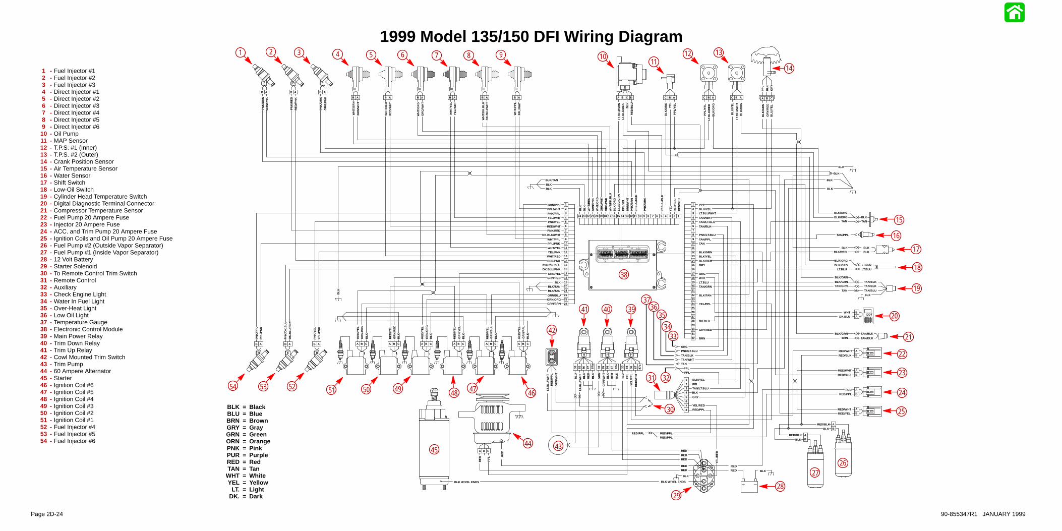
BLK = BlackBLU = BlueBRN = BrownGRY = GrayGRN = GreenORN = OrangePNK = PinkPUR = PurpleRED = RedTAN = Tan
WHT = WhiteYEL = Yellow
LT. = LightDK. = Dark
1999 Model 135/150 DFI Wiring Diagram
RE
D/B
LU
RE
D/B
LU
YE
L
LT.B
LU/B
LK
PN
K/O
RG
LT.B
LU/R
ED
PN
K/B
RN
BR
N/W
HT
BLK
/OR
GW
HT
/DK
.BLU
OR
G/P
NK
OR
G/W
HT
BR
N/P
NK
WH
T/B
RN
BLK
RE
D/Y
EL
PPLBLU/YEL
TAN/BLK
PNK/LT.BLU
TAN/PPLTAN
BLK/GRNBLK/YEL
WHT
LT.BLU
BLK/TAN
GRY/RED
GR
N/R
ED
RE
D/Y
EL
GR
N/O
RG
RE
D/Y
EL
GR
N/Y
EL
RE
D/Y
EL
GR
N/B
LU
RE
D/Y
EL
GR
N/P
PL
RE
D/Y
EL
GR
N/B
RN
WH
T/B
RN
BR
N/W
HT
WH
T/R
ED
RE
D/W
HT
WH
T/O
RG
OR
G/W
HT
WH
T/Y
EL
YE
L/W
HT
WH
T/D
K.B
LUD
K.B
LU/W
HT
WH
T/P
PL
PP
L/W
HT
GRN/PPLPPL/WHT
RED/WHTPNK/RED
DK.BLU/WHT
WHT/PPLPPL/PNK
WHT/YELYEL/PNK
WHT/RED
DK.BLU/PNK
GRN/YELGRN/RED
BLK
BLK/TAN
GRN/BLUGRN/ORG
PNK/PPLYEL/WHTPNK/YEL
RED/PNKPNK/DK.BLU
BLK/TAN
GRN/BRN
OR
G/P
NK
PN
K/O
RG
RE
D/P
NK
PN
K/R
ED
BR
N/P
NK
PN
K/B
RN
PP
L/Y
EL
LT.B
LU/G
RN
WH
T/O
RG
BLK
LT.B
LU/G
RN
LT.B
LU/B
LK BLK
PP
L/Y
EL
LT.B
LU/R
ED
BLK
/OR
G
BLK
/GR
NLT
.BLU
/WH
T
BLU
/YE
L
PP
L/Y
EL
YE
LB
LK/O
RG
LT.BLU/WHT
TAN/WHTTAN/LT.BLU
BLK/REDGRY
TAN/GRN
YEL/PPL
DK.BLU
BLK
/GR
N
GR
Y/R
ED
BLU
/YE
L
ORG
TAN/PPL
TANBLK/ORG
PNK/LT.BLU
TAN/BLKTAN/WHT
ORG
TANBLK
TAN/BLKTAN/BLK
TAN/BLU
BLK
TAN
DN
UP
BLK
DDT
BRNBLK
BLK
BLK
BLK
BLK
BLK
PPLPPL
BLK/GRNTAN/GRN
TAN
BLK/GRN
LT.BLU
LT.BLUBLK/ORG
LT.BLU
1
23
456
78
910
111213
141516
1718
192021
2223
24
1
23
456
78
910
111213
141516
1718
192021
2223
242526
272829
3031
32
12345678109 11121314151618171920212223241 2345678 109 11121314151617181920222324252627282921303132
21 345678109 1112131415161817192021222324
123456789101112131415161718192021222324
BLK
DK
.BLU
/PN
K
PN
K/D
K.B
LU
YE
L/P
NK
PN
K/Y
EL
PP
L/P
NK
PN
K/P
PL
B A B A B A
B A B A B A
B A B A B A B A B A B A
A B CA B CA B CA B CA B CA B C
C DBA B AC B AC B AC A B C
BLK
PP
L
GR
Y
BLK/ORG
BLK/ORG
BLKBLK
BLKBLK/RED
TAN/BLK
TAN/BLK
BLK/GRNBRN
1
234
56
78
BLK/YEL
PPLTAN/LT.BLUBLK
GRY
YEL/REDRED/PPL
DK.BLUWHT
AB
86 878530 87a
GR
N/W
HT
GR
N
RE
DB
LK BLK
86 878530 87a
PP
L
RE
D
RE
D/W
HT
YE
L/P
PL
RED
RED/WHT
RED/WHT
RED/BLK
RED/BLU
RED/WHTRED/YEL
RED/PPL
BA
BA
B
A
BA
86 878530 87a
LT.B
LU/W
HT
BLU
RE
DB
LK
BLK
RED
A B C
RE
D
PP
L
REDRED
BLK
YE
L/R
ED
RED
RED
RED
BARED/BLK
BLK
BLK W/YEL ENDSBLK W/YEL ENDS
RED
RED/PPLRED/PPL
RED/PPL
RE
D/P
PL
LT.B
LU/W
HT
GR
N/W
HT
BLK
BLK
BLK
BLK
BLK
BLK/TAN
BLK
RE
D
BARED/BLK
BLK
RE
D/B
LU
1 2 3 4 5 6 7 8 9 1011
12 13
14
15
16
17
18
19
20
21
22
23
24
25
2627
2829
30
31 32
3334
3536
37
38
394041
42
434445
464748495051525354
1 - Fuel Injector #12 - Fuel Injector #23 - Fuel Injector #34 - Direct Injector #15 - Direct Injector #26 - Direct Injector #37 - Direct Injector #48 - Direct Injector #59 - Direct Injector #610 - Oil Pump11 - MAP Sensor12 - T.P.S. #1 (Inner)13 - T.P.S. #2 (Outer)14 - Crank Position Sensor15 - Air Temperature Sensor16 - Water Sensor17 - Shift Switch18 - Low-Oil Switch19 - Cylinder Head Temperature Switch20 - Digital Diagnostic Terminal Connector21 - Compressor Temperature Sensor22 - Fuel Pump 20 Ampere Fuse23 - Injector 20 Ampere Fuse24 - ACC. and Trim Pump 20 Ampere Fuse25 - Ignition Coils and Oil Pump 20 Ampere Fuse26 - Fuel Pump #2 (Outside Vapor Separator)27 - Fuel Pump #1 (Inside Vapor Separator)28 - 12 Volt Battery29 - Starter Solenoid30 - To Remote Control Trim Switch31 - Remote Control32 - Auxiliary33 - Check Engine Light34 - Water In Fuel Light35 - Over-Heat Light36 - Low Oil Light37 - Temperature Gauge38 - Electronic Control Module39 - Main Power Relay40 - Trim Down Relay41 - Trim Up Relay42 - Cowl Mounted Trim Switch43 - Trim Pump44 - 60 Ampere Alternator45 - Starter46 - Ignition Coil #647 - Ignition Coil #548 - Ignition Coil #449 - Ignition Coil #350 - Ignition Coil #251 - Ignition Coil #152 - Fuel Injector #453 - Fuel Injector #554 - Fuel Injector #6
Page 2D-24 90-855347R1 JANUARY 1999

3A
FUEL PUMP
90-855347R1 JANUARY 1999 Page 3A-1
FUEL SYSTEMSection 3A – Pulse Crankcase Driven Fuel Pump
Table of Contents
Specifications 3A-1. . . . . . . . . . . . . . . . . . . . . . . . . . . . . . . . Fuel Pump Pressure @ W.O.T. 3A-1. . . . . . . . . . . . . . Fuel Pump Pressure @ Idle 3A-1. . . . . . . . . . . . . . . .
Special Tools 3A-1. . . . . . . . . . . . . . . . . . . . . . . . . . . . . . . . Fuel Pump 3A-2. . . . . . . . . . . . . . . . . . . . . . . . . . . . . . . . . . Fuel Pump Description/Operation 3A-3. . . . . . . . . . . . . .
Checking for Restricted Fuel Flow Caused byAnti-Siphon Valves 3A-4. . . . . . . . . . . . . . . . . . . . . . . . . . . Testing Fuel Pump 3A-5. . . . . . . . . . . . . . . . . . . . . . . . . . . Fuel Pump Removal/Disassembly 3A-6. . . . . . . . . . . . . .
Cleaning/Inspection 3A-7. . . . . . . . . . . . . . . . . . . . . . . . Reassembly/lnstallation 3A-7. . . . . . . . . . . . . . . . . . . .
Specifications
Fuel Pump Pressure @ W.O.T.Maximum – 10 psiNormal – 8-10 psiMinimum – 3 psi
Fuel Pump Pressure @ IdleNormal – 2-3 psiMinimum – 1 psi
NOTE: Electric fuel pump pressure, if used in conjunction with engine mechanical fuelpump, must be limited to no more than 4 psi.
Special Tools
1. Fuel Pressure Gauge (0–15 psi) (Obtain Locally)
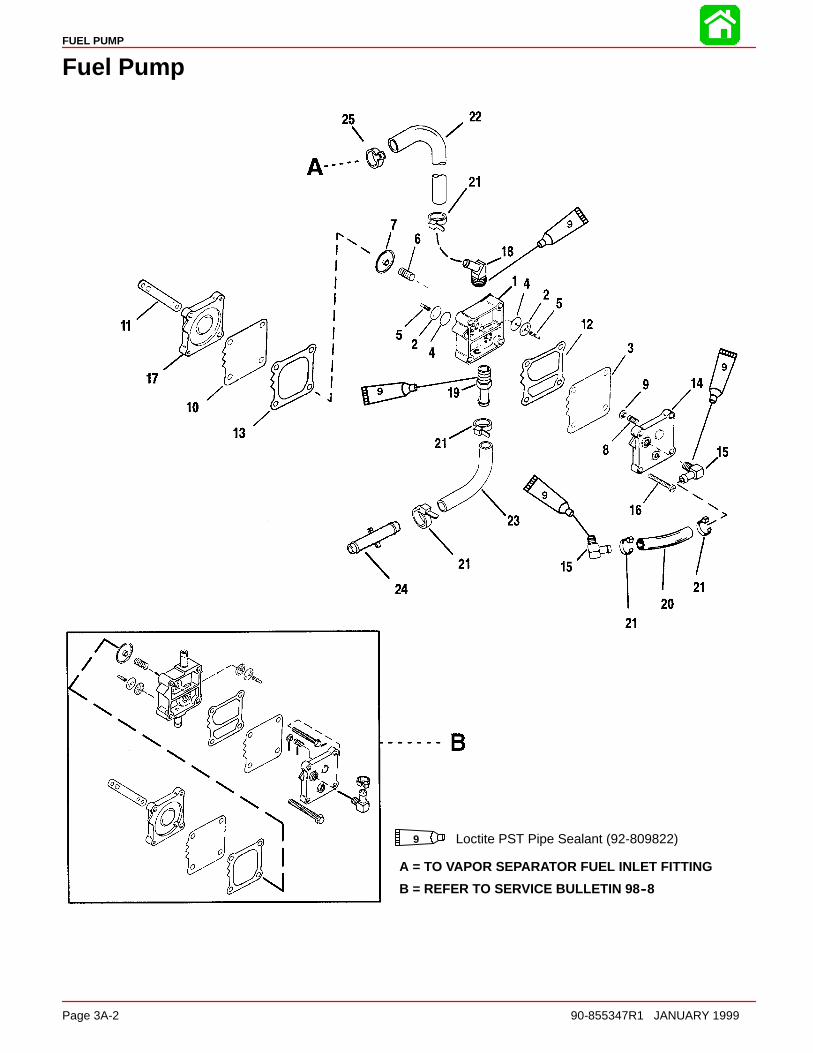
FUEL PUMP
Page 3A-2 90-855347R1 JANUARY 1999
Fuel Pump
Loctite PST Pipe Sealant (92-809822)9
A = TO VAPOR SEPARATOR FUEL INLET FITTINGB = REFER TO SERVICE BULLETIN 98--8
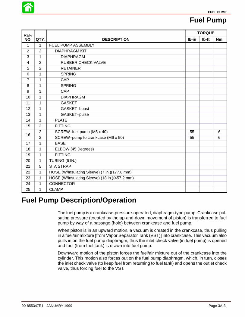
FUEL PUMP
90-855347R1 JANUARY 1999 Page 3A-3
Fuel Pump
REF. TORQUEREF.NO. QTY. DESCRIPTION lb-in lb-ft Nm.
1 1 FUEL PUMP ASSEMBLY
2 2 DIAPHRAGM KIT3 1 DIAPHRAGM4 2 RUBBER CHECK VALVE5 2 RETAINER6 1 SPRING7 1 CAP
8 1 SPRING9 1 CAP10 1 DIAPHRAGM11 1 GASKET12 1 GASKET–boost13 1 GASKET–pulse14 1 PLATE
15 2 FITTING
162 SCREW–fuel pump (M5 x 40) 55 6
162 SCREW–pump to crankcase (M6 x 50) 55 6
17 1 BASE18 1 ELBOW (45 Degrees)19 1 FITTING20 1 TUBING (6 IN.)
21 5 STA STRAP22 1 HOSE (W/Insulating Sleeve) (7 in.)(177.8 mm)23 1 HOSE (W/Insulating Sleeve) (18 in.)(457.2 mm)24 1 CONNECTOR25 1 CLAMP
Fuel Pump Description/Operation
The fuel pump is a crankcase-pressure-operated, diaphragm-type pump. Crankcase pul-sating pressure (created by the up-and-down movement of piston) is transferred to fuelpump by way of a passage (hole) between crankcase and fuel pump.
When piston is in an upward motion, a vacuum is created in the crankcase, thus pullingin a fuel/air mixture [from Vapor Separator Tank (VST)] into crankcase. This vacuum alsopulls in on the fuel pump diaphragm, thus the inlet check valve (in fuel pump) is openedand fuel (from fuel tank) is drawn into fuel pump.
Downward motion of the piston forces the fuel/air mixture out of the crankcase into thecylinder. This motion also forces out on the fuel pump diaphragm, which, in turn, closesthe inlet check valve (to keep fuel from returning to fuel tank) and opens the outlet checkvalve, thus forcing fuel to the VST.
FUEL PUMP
Page 3A-4 90-855347R1 JANUARY 1999
CHECKING for RESTRICTED FUEL FLOW CAUSED byANTI-SIPHON VALVES
While anti-siphon valves may be helpful from a safety stand-point, they clog with debris,they may be too small, or they may have too heavy a spring. Summarizing, the pressuredrop across these valves can, and often does, create operational problems and/or pow-er-head damage by restricting fuel to the fuel pump and VST. Some symptoms of re-stricted (lean) fuel flow, which could be caused by use of an anti-siphon valve, are:
1 - Loss of fuel pump pressure 2 - Loss of power 3 - High speed surging 4 - Preignition/detonation (piston dome erosion)5 - Outboard cuts out or hesitates upon acceleration 6 - Outboard runs rough7 - Outboard quits and cannot be restarted 8 - Outboard will not start 9 - Vapor lock
Since any type of anti-siphon device must be located between the outboard fuel inlet andfuel tank outlet, a simple method of checking [if such a device (or bad fuel) is a problemsource] is to operate the outboard with a separate fuel supply which is known to be good,such as a remote fuel tank.
If, after using a separate fuel supply, it is found that the anti-siphon valve is the cause ofthe problem, there are 2 solutions to the problem; either 1) remove the anti- siphon valveor 2) replace it with a solenoid-operated fuel shut off valve.
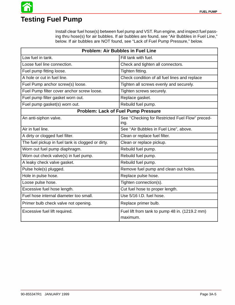
FUEL PUMP
90-855347R1 JANUARY 1999 Page 3A-5
Testing Fuel Pump
Install clear fuel hose(s) between fuel pump and VST. Run engine, and inspect fuel pass-ing thru hose(s) for air bubbles. If air bubbles are found, see “Air Bubbles in Fuel Line,”below. If air bubbles are NOT found, see “Lack of Fuel Pump Pressure,” below.
Problem: Air Bubbles in Fuel LineLow fuel in tank. Fill tank with fuel.
Loose fuel line connection. Check and tighten all connectors.
Fuel pump fitting loose. Tighten fitting.
A hole or cut in fuel line. Check condition of all fuel lines and replace
Fuel Pump anchor screw(s) loose. Tighten all screws evenly and securely.
Fuel Pump filter cover anchor screw loose. Tighten screws securely.
Fuel pump filter gasket worn out. Replace gasket.
Fuel pump gasket(s) worn out. Rebuild fuel pump.
Problem: Lack of Fuel Pump PressureAn anti-siphon valve. See ‘‘Checking for Restricted Fuel Flow” preced-
ing.
Air in fuel line. See ‘‘Air Bubbles in Fuel Line”, above.
A dirty or clogged fuel filter. Clean or replace fuel filter.
The fuel pickup in fuel tank is clogged or dirty. Clean or replace pickup.
Worn out fuel pump diaphragm. Rebuild fuel pump.
Worn out check valve(s) in fuel pump. Rebuild fuel pump.
A leaky check valve gasket. Rebuild fuel pump.
Pulse hole(s) plugged. Remove fuel pump and clean out holes.
Hole in pulse hose. Replace pulse hose.
Loose pulse hose. Tighten connection(s).
Excessive fuel hose length. Cut fuel hose to proper length.
Fuel hose internal diameter too small. Use 5/16 I.D. fuel hose.
Primer bulb check valve not opening. Replace primer bulb.
Excessive fuel lift required. Fuel lift from tank to pump 48 in. (1219.2 mm)maximum.

FUEL PUMP
Page 3A-6 90-855347R1 JANUARY 1999
Fuel Pump Removal/DisassemblyIMPORTANT: Fuel pump diaphragm and gaskets should not be re-used once fuelpump is disassembled.
NOTE: External low pressure electric fuel pump and vapor separator has been removedfrom illustration to provide improved visual clarity for location of mechanical fuel pump.
1. Disconnect fuel hoses from fuel pump.
2. Disconnect pulse hose.
3. Remove two mounting screws.
4. Remove fuel pump from engine.
a
e
57298
c d
b
a - Fuel hose from tank to fuel pumpb - Fuel hose from fuel pump to Water Separatorc - Pulse hosed - Mounting screwse - Fuel pump
5. Disassemble fuel pump.

FUEL PUMP
90-855347R1 JANUARY 1999 Page 3A-7
Cleaning/Inspection1. Clean fuel pump housing, check valves, pulse chamber and pump base in solvent and
dry all but check valves with compressed air.
2. Inspect each check valve for splits, chips and for proper sealing against pump hous-ing.
3. Inspect boost springs for weakness or breakage.
4. Inspect fuel pump housing, pulse chamber and base for cracks or rough gasket sur-face and replace if any are found.
5. Inspect fitting on fuel pump housing for loosening or any signs of fuel or air leaks. Re-place or tighten fitting if a leak is found.
Reassembly/lnstallationASSEMBLY
1. Insert retainer thru plastic disc and rubber check valve.
23601
a
b
c
a - Retainerb - Plastic Discc - Rubber Check Valve
2. Install check valves and retainers into fuel pump body.

FUEL PUMP
Page 3A-8 90-855347R1 JANUARY 1999
3. With retainer installed in pump body, break retainer rod from retainer by bending side-ways.
23601
a
b
a - Rodb - Retainer Cap
4. Reinstall rod into retainer cap and, use a small hammer or hammer and punch to taprod down into retainer until flush with top of retainer.
23601
a
b
a - Rodb - Retainer Cap
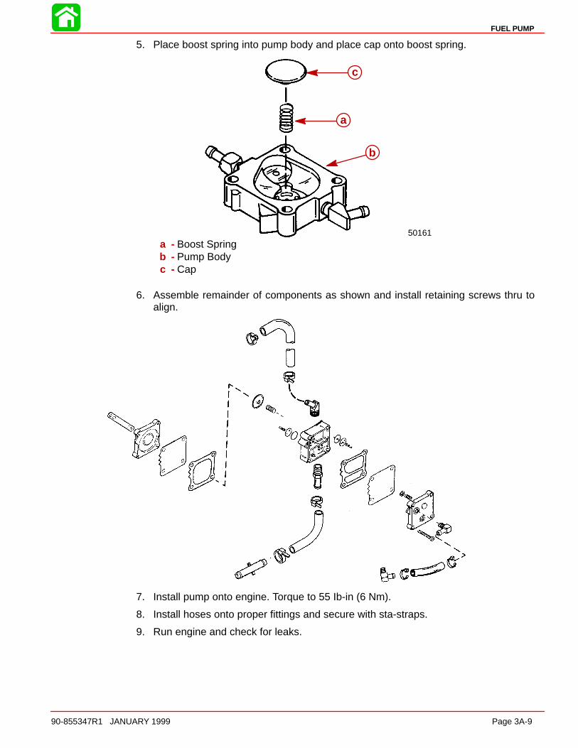
FUEL PUMP
90-855347R1 JANUARY 1999 Page 3A-9
5. Place boost spring into pump body and place cap onto boost spring.
50161
a
b
c
a - Boost Springb - Pump Bodyc - Cap
6. Assemble remainder of components as shown and install retaining screws thru toalign.
7. Install pump onto engine. Torque to 55 Ib-in (6 Nm).
8. Install hoses onto proper fittings and secure with sta-straps.
9. Run engine and check for leaks.
3B
DIRECT FUEL INJECTION
90-855347R1 JANUARY 1999 Page 3B-1
FUEL SYSTEMSection 3B – Direct Fuel Injection
Table of Contents
Specifications 3B-2. . . . . . . . . . . . . . . . . . . . . . . . . . . . . . . . Special Tools 3B-3. . . . . . . . . . . . . . . . . . . . . . . . . . . . . . . . Notes: 3B-5. . . . . . . . . . . . . . . . . . . . . . . . . . . . . . . . . . . . . . Air Handler 3B-6. . . . . . . . . . . . . . . . . . . . . . . . . . . . . . . . . . Air Handler Components 3B-8. . . . . . . . . . . . . . . . . . . . . . Vapor Separator Components 3B-10. . . . . . . . . . . . . . . . . Fuel Rails/Air Compressor Hose Routing 3B-12. . . . . . . Fuel Rails 3B-14. . . . . . . . . . . . . . . . . . . . . . . . . . . . . . . . . . Air Compressor Components 3B-16. . . . . . . . . . . . . . . . . DFI Operation 3B-18. . . . . . . . . . . . . . . . . . . . . . . . . . . . . .
Air Induction Through Crankcase 3B-18. . . . . . . . . . . Air Compressor System 3B-18. . . . . . . . . . . . . . . . . . . Fuel 3B-18. . . . . . . . . . . . . . . . . . . . . . . . . . . . . . . . . . . . Oil 3B-19. . . . . . . . . . . . . . . . . . . . . . . . . . . . . . . . . . . . . . Electrical 3B-19. . . . . . . . . . . . . . . . . . . . . . . . . . . . . . . . Operation 3B-19. . . . . . . . . . . . . . . . . . . . . . . . . . . . . . .
Testing Electric Fuel Pump Pressure Output 3B-20. . . . Low Pressure Electric Fuel Pump 3B-20. . . . . . . . . . . High Pressure Electric Fuel Pump 3B-21. . . . . . . . . .
Fuel Management Assembly Removal 3B-22. . . . . . . . . Reed Block Assembly Removal 3B-25. . . . . . . . . . . . Reed Block Assembly Installation 3B-25. . . . . . . . . . .
Air Temperature Sensor Removal 3B-25. . . . . . . . . . Air Temperature Sensor Installation 3B-26. . . . . . . . . Throttle Plate Assembly Removal 3B-26. . . . . . . . . . . Throttle Plate Assembly Installation 3B-26. . . . . . . . . Vapor Separator Disassembly 3B-26. . . . . . . . . . . . . . Vapor Separator Reassembly 3B-28. . . . . . . . . . . . . . Air Plenum Installation 3B-29. . . . . . . . . . . . . . . . . . . . Low Pressure Electric Fuel Pump Installation 3B-29. Vapor Separator Installation 3B-31. . . . . . . . . . . . . . . Fuel Rail Removal 3B-33. . . . . . . . . . . . . . . . . . . . . . . . Fuel Rail Disassembly 3B-34. . . . . . . . . . . . . . . . . . . . Fuel Pressure Regulator 3B-37. . . . . . . . . . . . . . . . . . Air Pressure Regulator 3B-39. . . . . . . . . . . . . . . . . . . . Tracker Valve 3B-41. . . . . . . . . . . . . . . . . . . . . . . . . . . . Fuel Rail Cleaning 3B-43. . . . . . . . . . . . . . . . . . . . . . . . Direct Injector Removal 3B-43. . . . . . . . . . . . . . . . . . . Fuel Rail and Direct Injector Installation 3B-45. . . . . Air Compressor 3B-46. . . . . . . . . . . . . . . . . . . . . . . . . . Air Compressor Disassembly/Reassembly 3B-49. . . Air Compressor Flow Diagram 3B-50. . . . . . . . . . . . . Air Compressor Pressure Test 3B-51. . . . . . . . . . . . .
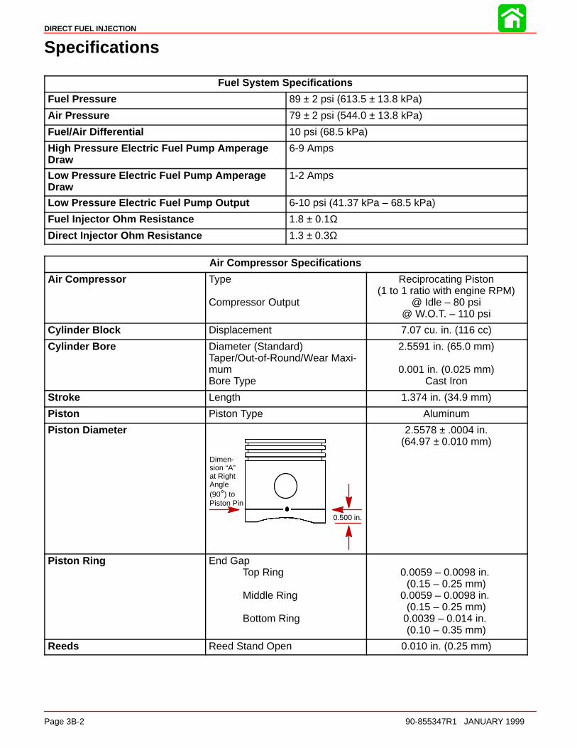
DIRECT FUEL INJECTION
Page 3B-2 90-855347R1 JANUARY 1999
Specifications
Fuel System Specifications
Fuel Pressure 89 ± 2 psi (613.5 ± 13.8 kPa)
Air Pressure 79 ± 2 psi (544.0 ± 13.8 kPa)
Fuel/Air Differential 10 psi (68.5 kPa)
High Pressure Electric Fuel Pump AmperageDraw
6-9 Amps
Low Pressure Electric Fuel Pump AmperageDraw
1-2 Amps
Low Pressure Electric Fuel Pump Output 6-10 psi (41.37 kPa – 68.5 kPa)
Fuel Injector Ohm Resistance 1.8 ± 0.1ΩDirect Injector Ohm Resistance 1.3 ± 0.3Ω
Air Compressor Specifications
Air Compressor Type
Compressor Output
Reciprocating Piston(1 to 1 ratio with engine RPM)
@ Idle – 80 psi@ W.O.T. – 110 psi
Cylinder Block Displacement 7.07 cu. in. (116 cc)
Cylinder Bore Diameter (Standard)Taper/Out-of-Round/Wear Maxi-mumBore Type
2.5591 in. (65.0 mm)
0.001 in. (0.025 mm)Cast Iron
Stroke Length 1.374 in. (34.9 mm)
Piston Piston Type Aluminum
Piston Diameter
Dimen-sion “A”at RightAngle(90°) toPiston Pin
0.500 in.
2.5578 ± .0004 in.(64.97 ± 0.010 mm)
Piston Ring End GapTop Ring
Middle Ring
Bottom Ring
0.0059 – 0.0098 in. (0.15 – 0.25 mm)
0.0059 – 0.0098 in. (0.15 – 0.25 mm)
0.0039 – 0.014 in. (0.10 – 0.35 mm)
Reeds Reed Stand Open 0.010 in. (0.25 mm)
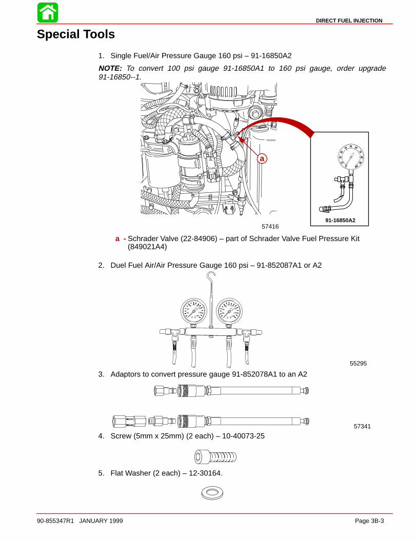
DIRECT FUEL INJECTION
90-855347R1 JANUARY 1999 Page 3B-3
Special Tools
1. Single Fuel/Air Pressure Gauge 160 psi – 91-16850A2
NOTE: To convert 100 psi gauge 91-16850A1 to 160 psi gauge, order upgrade91-16850--1.
5741691-16850A2
a
a - Schrader Valve (22-84906) – part of Schrader Valve Fuel Pressure Kit(849021A4)
2. Duel Fuel Air/Air Pressure Gauge 160 psi – 91-852087A1 or A2
55295
3. Adaptors to convert pressure gauge 91-852078A1 to an A2
57341
4. Screw (5mm x 25mm) (2 each) – 10-40073-25
5. Flat Washer (2 each) – 12-30164.

DIRECT FUEL INJECTION
Page 3B-4 90-855347R1 JANUARY 1999
6. Seal/Teflon Ring Installation Tool – 91-851980
56015
7. Seal/Teflon Ring Sizing Tool – 91-851980-1
560148. DMT 2000 Digital Tachometer Multi-meter P/N 91-854009A1
9. Clamp Tool Kit 91-803146A2
57316
a
a - Clamp Tool 91-803146T

DIRECT FUEL INJECTION
90-855347R1 JANUARY 1999 Page 3B-5
Notes:

DIRECT FUEL INJECTION
Page 3B-6 90-855347R1 JANUARY 1999
Air Handler
A = OIL LINE TO COMPRESSORB = TO FITTING IN FLYWHEEL COVERC = PRESS INTO TUBING
Loctite Superbonder 454 GEL96
10
25
12
2
30
3
26
8
1
2
30
56
A
35
96
4
29
27
36
28
9
13
16
1920
21
22 23
17
17
17
18
24
7
33
3331
32
B
C34
37
15
38
39
40
11
14
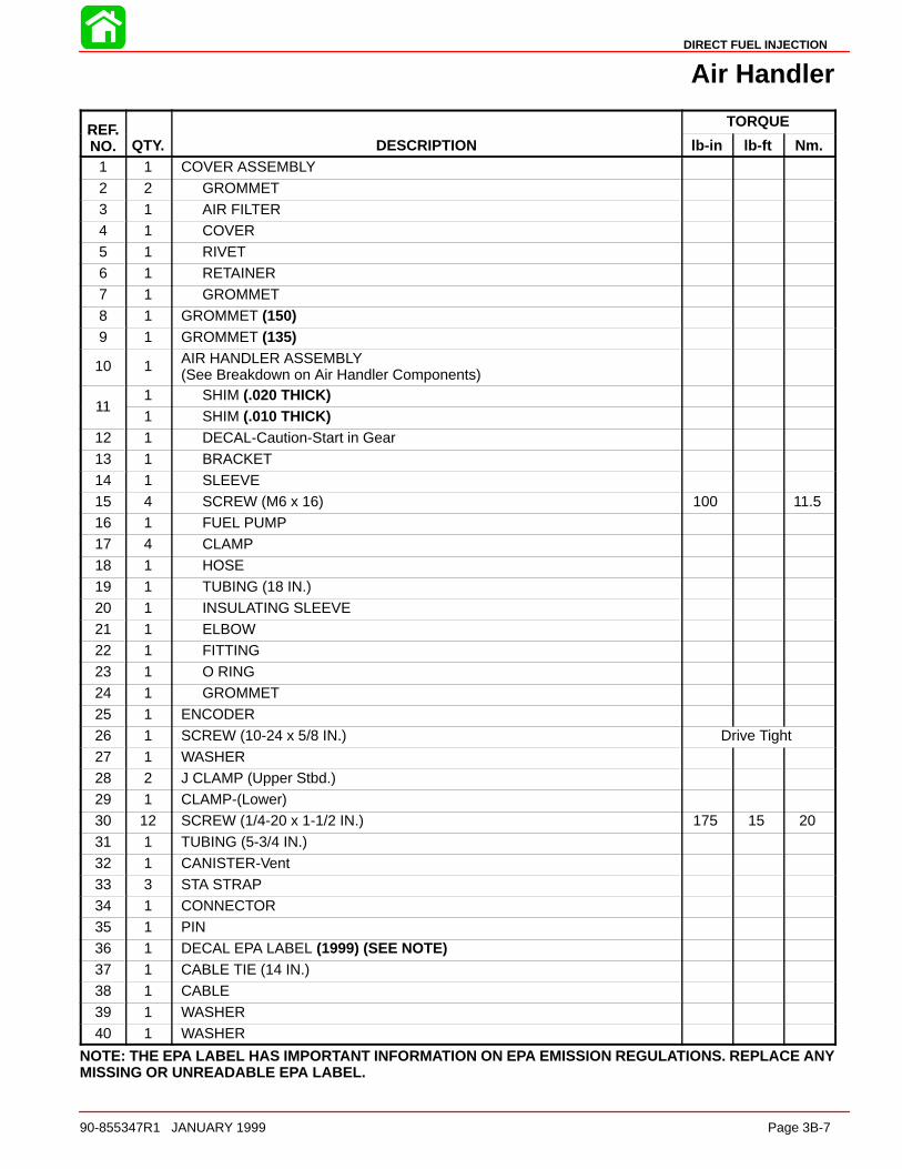
DIRECT FUEL INJECTION
90-855347R1 JANUARY 1999 Page 3B-7
Air Handler
REF. TORQUEREF.NO. QTY. DESCRIPTION lb-in lb-ft Nm.
1 1 COVER ASSEMBLY
2 2 GROMMET3 1 AIR FILTER4 1 COVER5 1 RIVET6 1 RETAINER7 1 GROMMET
8 1 GROMMET (150)9 1 GROMMET (135)
10 1 AIR HANDLER ASSEMBLY(See Breakdown on Air Handler Components)
111 SHIM (.020 THICK)
111 SHIM (.010 THICK)
12 1 DECAL-Caution-Start in Gear13 1 BRACKET14 1 SLEEVE15 4 SCREW (M6 x 16) 100 11.516 1 FUEL PUMP17 4 CLAMP
18 1 HOSE19 1 TUBING (18 IN.)20 1 INSULATING SLEEVE21 1 ELBOW22 1 FITTING23 1 O RING24 1 GROMMET
25 1 ENCODER26 1 SCREW (10-24 x 5/8 IN.) Drive Tight27 1 WASHER28 2 J CLAMP (Upper Stbd.)29 1 CLAMP-(Lower)30 12 SCREW (1/4-20 x 1-1/2 IN.) 175 15 2031 1 TUBING (5-3/4 IN.)
32 1 CANISTER-Vent33 3 STA STRAP34 1 CONNECTOR35 1 PIN36 1 DECAL EPA LABEL (1999) (SEE NOTE)37 1 CABLE TIE (14 IN.)38 1 CABLE
39 1 WASHER40 1 WASHER
NOTE: THE EPA LABEL HAS IMPORTANT INFORMATION ON EPA EMISSION REGULATIONS. REPLACE ANYMISSING OR UNREADABLE EPA LABEL.

DIRECT FUEL INJECTION
Page 3B-8 90-855347R1 JANUARY 1999
Air Handler Components
1
4
2
35
6
7
8
13
14
15
16
910
17
1920
21
22
23
25
26
27
15
1413
9
9
10
18
24
A11
12
16
A = OIL LINE TO COMPRESSOR

DIRECT FUEL INJECTION
90-855347R1 JANUARY 1999 Page 3B-9
Air Handler Components
REF. TORQUEREF.NO. QTY. DESCRIPTION lb-in lb-ft Nm.
– 1 AIR HANDLER
1 1 ADAPTOR PLATE KIT2 1 GASKET3 1 GASKET4 6 REED BLOCK5 12 SCREW (1/4-20 x .88) 100 11.56 1 OIL PUMP
7 1 GASKET8 1 BRACKET9 3 FITTING10 3 FITTING11 1 ELBOW12 1 FITTING (STRAIGHT)13 6 BUSHING
14 6 GROMMET15 6 SCREW 140 12 1616 6 WASHER17 1 AIR PLENUM KIT18 1 ELBOW
191 ELBOW (.236 O.D.)
191 ELBOW (.159 O.D.)
20 1 GASKET21 1 TEMPERATURE SENSOR22 3 SCREW Drive Tight23 3 LOCKWASHER24 12 SCREW (M4 x 16) Drive Tight25 1 THROTTLE BODY KIT26 1 O RING
27 4 SCREW 100 11.5
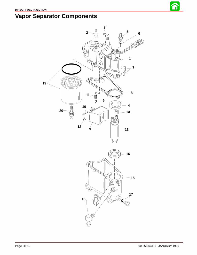
DIRECT FUEL INJECTION
Page 3B-10 90-855347R1 JANUARY 1999
Vapor Separator Components
1
2 5
7
8
9
10
11
1213
14
15
16
1718
19
20
6
49
3

DIRECT FUEL INJECTION
90-855347R1 JANUARY 1999 Page 3B-11
Vapor Separator Components
REF. TORQUEREF.NO. QTY. DESCRIPTION lb-in lb-ft Nm.
1 1 COVER KIT2 1 FITTING - Straight3 1 ELBOW4 1 SEAL5 1 FITTING KIT-Pump Outlet6 1 O RING7 7 SCREW 30 3.5
8 1 GASKET9 1 FLOAT KIT10 1 FLOAT PIN11 1 NEEDLE VALVE12 1 SCREW 10 1.013 1 FUEL PUMP KIT
14 1 SLEEVE15 1 BOWL KIT16 1 SEAL17 1 PLUG KIT18 2 ELBOW19 1 FUEL FILTER ASSEMBLY20 1 PROBE
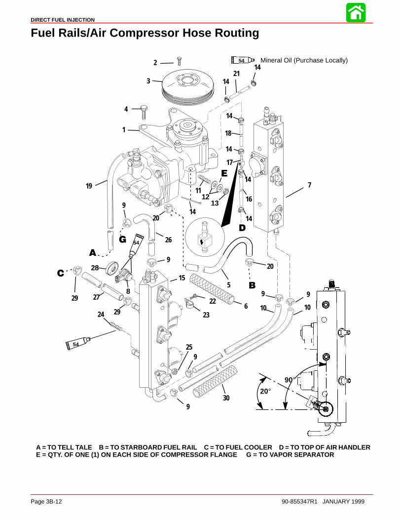
DIRECT FUEL INJECTION
Page 3B-12 90-855347R1 JANUARY 1999
Fuel Rails/Air Compressor Hose Routing
Mineral Oil (Purchase Locally)542
3
1
4
5
7
9
10
1116
17
18
19
20
21
22
2324
25
26
27
28
8
9
9
9
99
10
1213
14
14
14
14
14
15
20°
14
20
90°
54
629
29
14
30
54
A = TO TELL TALE B = TO STARBOARD FUEL RAIL C = TO FUEL COOLER D = TO TOP OF AIR HANDLERE = QTY. OF ONE (1) ON EACH SIDE OF COMPRESSOR FLANGE G = TO VAPOR SEPARATOR

DIRECT FUEL INJECTION
90-855347R1 JANUARY 1999 Page 3B-13
Fuel Rails/Air Compressor Hose Routing
REF. TORQUEREF.NO. QTY. DESCRIPTION lb-in lb-ft Nm.
1 1 AIR COMPRESSOR (See breakdown on Air Compressor Components)
2 5 SCREW (M6 x 12) 100 11.53 1 PULLEY4 2 SCREW 40 545 1 HOSE
6 1 INSULATOR SLEEVE (16 IN.)7 1 FUEL RAIL (STARBOARD)8 6 INJECTOR9 4 CLAMP10 2 HOSE (16 IN.)11 1 STUD12 2 WASHER
13 1 NUT 25 3414 8 STA STRAP15 1 FUEL RAIL (PORT)16 1 TUBING (22-1/2 IN.)17 1 CHECK VALVE18 1 TUBING (2-1/2 IN.)
19 1 TUBING (28-1/2 IN.)20 2 CLAMP21 1 TUBING (28-1/2 IN.)22 4 SCREW (M5 x 10)23 4 CLAMP24 4 STUD25 4 NUT 33 45
26 1 HOSE (30 IN.) (W/INSULATING SLEEVE)27 1 HOSE (W/INSULATING SLEEVE)28 6 CUPPED WASHER29 4 CLAMP30 1 INSULATOR SLEEVE (18 IN.)

DIRECT FUEL INJECTION
Page 3B-14 90-855347R1 JANUARY 1999
Fuel Rails
1
2
3
4
5
6
7
8
910
11
1213
14
15
1617
18
19
20
21
22
1
4
44
5
55
12
13
5
21
22
2222

DIRECT FUEL INJECTION
90-855347R1 JANUARY 1999 Page 3B-15
Fuel Rails
REF. TORQUEREF.NO. QTY. DESCRIPTION lb-in lb-ft Nm.
1 2 SCHRADER VALVE KIT (air and fuel)
2 1 FITTING (air inlet)3 1 FITTING (fuel inlet)4 4 CLAMP (fitting retainer)5 10 SCREW M5X8 70 86 1 RAIL (starboard) w/out injectors7 4 SCREW M5X16 70 8
8 1 COVER (tracker valve)9 1 SPRING (tracker valve)10 1 DIAPHRAGM (tracker valve)11 1 O-RING (tracker cover)12 2 FITTING (air/fuel) starboard13 2 FITTING (air/fuel) port14 6 RETAINER (injector) DESIGN II
15 6 RETAINER (injector) DESIGN I16 6 INJECTOR (fuel)17 O-RING KIT (large) 6 per kit18 O-RING KIT (small) 6 per kit19 2 FITTING20 1 RAIL (port) w/out injectors21 O-RING (2 per kit)
22 O-RING fitting/schrader (16 per kit)

DIRECT FUEL INJECTION
Page 3B-16 90-855347R1 JANUARY 1999
Air Compressor Components
1
2
5
6
7
8
9
10
13
14
15
16
4
17
20
2122
19 ÇÇÇÇÇÇÇÇÇÇÇÇ
8
9
11
12
11
18 18
27
3
23
24
25
26
9
9
14
14
14
14
9
9
6Dielectric Grease (92-823506--1)6
Loctite PST Pipe Sealant (92-809822)9
14 2 Cycle Outboard Oil (92-826666A24)
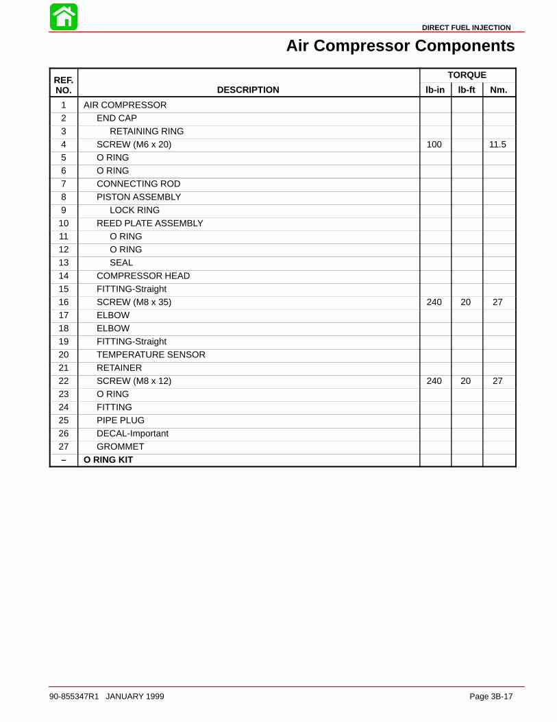
DIRECT FUEL INJECTION
90-855347R1 JANUARY 1999 Page 3B-17
Air Compressor Components
REF. TORQUEREF.NO. DESCRIPTION lb-in lb-ft Nm.
1 AIR COMPRESSOR2 END CAP3 RETAINING RING4 SCREW (M6 x 20) 100 11.55 O RING6 O RING7 CONNECTING ROD
8 PISTON ASSEMBLY9 LOCK RING10 REED PLATE ASSEMBLY11 O RING12 O RING13 SEAL
14 COMPRESSOR HEAD15 FITTING-Straight16 SCREW (M8 x 35) 240 20 2717 ELBOW18 ELBOW19 FITTING-Straight20 TEMPERATURE SENSOR
21 RETAINER22 SCREW (M8 x 12) 240 20 2723 O RING24 FITTING25 PIPE PLUG26 DECAL-Important27 GROMMET
– O RING KIT
DIRECT FUEL INJECTION
Page 3B-18 90-855347R1 JANUARY 1999
DFI Operation
Air Induction Through CrankcaseCombustion air enters the cowl through holes located in the top aft end of the cowl. Thecowl liner directs this air to the bottom of the powerhead. This limits the exposure of saltair to the components inside the engine cowl.
Once inside the cowl the air enters the plenum through the throttle shutter which are lo-cated in the plenum assembly. The air then continues through the reed valves and intothe crankcase. The throttle shutter are actuated by the throttle shaft. Mounted onto a sep-arate shaft are two throttle position sensors (TPS). These sensors tell the engine controlunit (ECM) the position of the throttle.
2 TPS’s are installed on the DFI engine for safety redundancy. If one TPS should fail, thedash mounted CHECK ENGINE light will flash and the warning horn will sound. enginespeed will be reduced to 3000 RPM. If both TPS’s should fail, engine speed will be re-duced to idle. DFI engines require large amounts of air into the cylinders at idle speed.To accomplish this, the throttle shutters are partially open at low engine speeds. The dualTPS system reads the shaft movement in both directions, one reads movement up (in-creasing resistance), while the other reads the same movement as down (decreasing re-sistance). The ECM reads both and calculates the throttle shutter position.
Air Compressor SystemAir from inside the engine cowl is drawn into the compressor through the flywheel cover.This cover acts like a muffler to quiet compressor noise and contains a filter to preventthe ingestion of debris into the compressor. The compressor is driven by a serpentine beltfrom a pulley mounted on the crankshaft, and is automatically self adjusted using a singleidler pulley. This air compressor is a single cylinder unit containing a connecting rod, pis-ton, rings, bearings, reed valves, and a crankshaft. The compressor is water cooled tolower the temperature of the air charge and is lubricated by oil from the engine oil pumpassembly. As the compressor piston moves downward inside the cylinder, air is pulledthrough the filter, reed valves and into the cylinder. After the compressor piston changesdirection, the intake reeds close and the exhaust reeds open allowing compressed air intothe hose leading to the air/fuel rails.
The air/fuel rails contain two passages; one for fuel, the second is the air passage. Theair passage is common between all the cylinders included in the rail. A hose connects thestarboard rail air passage to the air compressor. Another hose connects the starboard airrail passage to the port air rail passage. An air pressure regulator will limit the amount ofpressure developed inside the air passages to approximately 10 psi below the pressureof the fuel inside the fuel passages (i.e. 80 psi air vs 90 psi fuel). Air exiting the pressureregulator is returned into the exhaust adaptor and exits thru the propeller.
FuelFuel for the engine is stored in a typical fuel tank. A primer bulb is installed into the fuelline to allow priming of the fuel system. A crankcase mounted pulse driven diaphragm fuelpump draws fuel through the fuel line, primer bulb, fuel pump assembly and then pushesthe fuel thru a water separating fuel filter. This filter removes any contaminates and waterbefore the fuel reaches the vapor separator. Fuel vapors are bled through a vent cannisterinto the air compressor inlet in the front of the flywheel cover. The electric fuel pump isdifferent than the fuel pump that is utilized on the standard EFI engine (non DFI), and iscapable of developing fuel pressures in excess of 90 psi. Fuel inside the rail must remainpressurized at exactly 10 psi over the air rail pressure or the ECM (map) calibrations willbe incorrect. Fuel from the vapor separator is supplied to the top of one fuel rail. A fuelline connects the bottom of the first rail to the opposite fuel rail. Fuel is stored inside the
DIRECT FUEL INJECTION
90-855347R1 JANUARY 1999 Page 3B-19
rail until an injector opens. A fuel pressure regulator controls pressure in the fuel rails, andallows excess fuel to return into the vapor separator. The fuel regulator not only regulatesfuel pressure but also regulates it at approximately 10 p.s.i. higher than whatever the airrail pressure is. The fuel regulator diaphragm is held closed with a spring that requires 10p.s.i. to force the diaphragm off the diaphragm seat. The back side of the diaphragm isexposed to air rail pressure. As the air rail pressure increases, the fuel pressure neededto open the regulator will equally increase. Example: If there is 50 p.s.i. of air pressure onthe air rail side of the diaphragm, 60 p.s.i. of fuel pressure will be required to open theregulator. The return fuel line to the vapor separator is water cooled.
To equalize the pulses developed by the pumps (both air and fuel) a tracker diaphragm(3) is installed in the starboard rail. The tracker diaphragm is positioned between the fueland air passages. The tracker diaphragm is a rubber diaphragm which expands and re-tracts depending upon which side of the diaphragm senses the pressure increase (pulse).
OilOil in this engine is not mixed with the fuel before entering the combustion chamber. Oilis stored inside a standard remote oil reservoir. Crankcase pressure will force oil from theremote oil reservoir into the oil storage reservoir on the side of the powerhead. Oil will flowfrom the oil storage tank into the oil pump. The oil pump is a solenoid design. It is activatedby the ECM and includes 7 pistons with corresponding discharge ports. The oil pump ismounted directly onto the powerhead. Each cylinder is lubricated by one of the dischargeports. The oil is discharged into the crankcase. The seventh passage connects to thehose that leads to the air compressor for lubrication. Excess oil from the compressor re-turns into the plenum and is ingested through the crankcase.
The ECM will change the discharge rate of the oil pump, depending upon engine demand.The ECM will also pulse the pump on initial start up to fill the oil passages eliminating theneed to bleed the oil system. The ECM provides additional oil for break in, as determinedby its internal clock. The oil ratio varies with engine rpm and load.
ElectricalThe electrical system consists of the ECM, crank position sensor (flywheel speed & crank-shaft position), throttle position sensor (TPS), MAP sensor, engine temperature sensor,ignition coils and injectors (fuel & direct). The engine requires a battery to start (i.e. theignition and injection will not occur if the battery is dead). The system will run off of thealternator.
OperationThe operation of the system happens in milliseconds (ms); exact timing is critical for en-gine performance. As the crankshaft rotates, air is drawn into the crankcase through thethrottle shutters, into the plenum, and through the reed valves. As the piston nears bot-tom-dead-center, air from the crankcase is forced through the transfer system into the cyl-inder. As the crankshaft continues to rotate the exhaust and intake ports close. With theseports closed, fuel can be injected into the cylinder. The ECM will receive a signal from thethrottle position sensor (TPS), engine temperature sensor (TS) and the crank positionsensor (flywheel speed and position sensor). With this information the ECM refers to thefuel calibration (maps) to determine when to activate (open and close) the injectors andfire the ignition coils. With the piston in the correct position, the ECM opens the fuel injec-tor, 90 psi fuel is discharged into a machined cavity inside the air chamber of the air/fuelrail. This mixes the fuel with the air charge. Next the direct injector will open, dischargingthe air/fuel mixture into the combustion chamber. The direct injector directs the mixtureat the bowl located in top of the piston. The piston’s bowl directs the air/fuel mixture intothe center of the combustion chamber. This air fuel mixture is then ignited by the sparkplug.
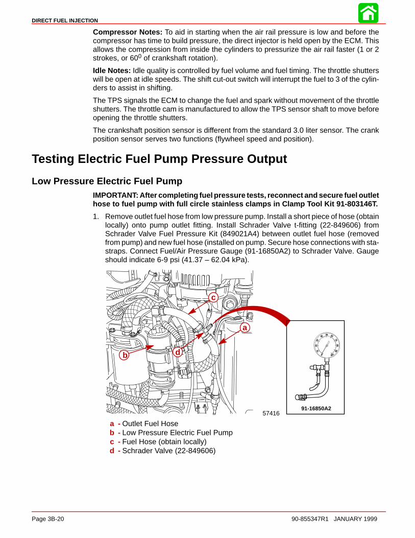
DIRECT FUEL INJECTION
Page 3B-20 90-855347R1 JANUARY 1999
Compressor Notes: To aid in starting when the air rail pressure is low and before thecompressor has time to build pressure, the direct injector is held open by the ECM. Thisallows the compression from inside the cylinders to pressurize the air rail faster (1 or 2strokes, or 600 of crankshaft rotation).
Idle Notes: Idle quality is controlled by fuel volume and fuel timing. The throttle shutterswill be open at idle speeds. The shift cut-out switch will interrupt the fuel to 3 of the cylin-ders to assist in shifting.
The TPS signals the ECM to change the fuel and spark without movement of the throttleshutters. The throttle cam is manufactured to allow the TPS sensor shaft to move beforeopening the throttle shutters.
The crankshaft position sensor is different from the standard 3.0 liter sensor. The crankposition sensor serves two functions (flywheel speed and position).
Testing Electric Fuel Pump Pressure Output
Low Pressure Electric Fuel PumpIMPORTANT: After completing fuel pressure tests, reconnect and secure fuel outlethose to fuel pump with full circle stainless clamps in Clamp Tool Kit 91-803146T.
1. Remove outlet fuel hose from low pressure pump. Install a short piece of hose (obtainlocally) onto pump outlet fitting. Install Schrader Valve t-fitting (22-849606) fromSchrader Valve Fuel Pressure Kit (849021A4) between outlet fuel hose (removedfrom pump) and new fuel hose (installed on pump. Secure hose connections with sta-straps. Connect Fuel/Air Pressure Gauge (91-16850A2) to Schrader Valve. Gaugeshould indicate 6-9 psi (41.37 – 62.04 kPa).
57416
a
b
c
91-16850A2
d
a - Outlet Fuel Hoseb - Low Pressure Electric Fuel Pumpc - Fuel Hose (obtain locally)d - Schrader Valve (22-849606)
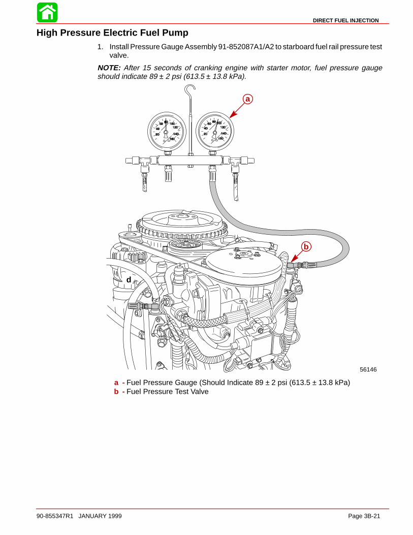
DIRECT FUEL INJECTION
90-855347R1 JANUARY 1999 Page 3B-21
High Pressure Electric Fuel Pump1. Install Pressure Gauge Assembly 91-852087A1/A2 to starboard fuel rail pressure test
valve.
NOTE: After 15 seconds of cranking engine with starter motor, fuel pressure gaugeshould indicate 89 ± 2 psi (613.5 ± 13.8 kPa).
56146
d
b
a
a - Fuel Pressure Gauge (Should Indicate 89 ± 2 psi (613.5 ± 13.8 kPa)b - Fuel Pressure Test Valve

DIRECT FUEL INJECTION
Page 3B-22 90-855347R1 JANUARY 1999
Fuel Management Assembly Removal
CAUTIONFuel system must be bled off prior to removal of fuel system components.
NOTE: Use Fuel/Air Pressure Gauge 91-16850--1 or 91-852087A1/A2 to de-pressurizeair hose first and then fuel hose.
1. De-pressurize fuel system.
b
aa
b
a - Starboard Fuel Railb - Fuel Pressure Port
2. Place suitable container underneath vapor separator drain plug and remove plug.
3. Disconnect electric fuel pump harness connector.
56049
a
b
57317
a - Drain Plugb - Sensor Lead
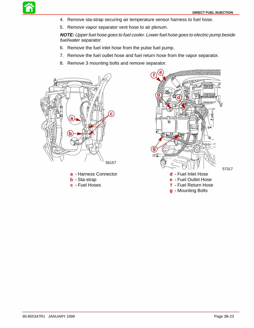
DIRECT FUEL INJECTION
90-855347R1 JANUARY 1999 Page 3B-23
4. Remove sta-strap securing air temperature sensor harness to fuel hose.
5. Remove vapor separator vent hose to air plenum.
NOTE: Upper fuel hose goes to fuel cooler. Lower fuel hose goes to electric pump besidefuel/water separator.
6. Remove the fuel inlet hose from the pulse fuel pump.
7. Remove the fuel outlet hose and fuel return hose from the vapor separator.
8. Remove 3 mounting bolts and remove separator.
56157
cca
b
g
g
fe
d
57317
a - Harness Connectorb - Sta-strapc - Fuel Hoses
d - Fuel Inlet Hosee - Fuel Outlet Hosef - Fuel Return Hoseg - Mounting Bolts

DIRECT FUEL INJECTION
Page 3B-24 90-855347R1 JANUARY 1999
9. Disconnect throttle cam link rod and the Throttle Position Sensor link rod.
10. Disconnect MAP Sensor hose and compressor oil return hose from air managementassembly.
56068
b
ac
d
ba
57317
a - Throttle Link Rodb - Throttle Position Sensor Link Rodc - MAP Sensor Hosed - Oil Return Hose
11. Disconnect oil hoses from oil pump.
12. Remove and plug oil inlet hose to oil pump.
13. Remove 12 bolts securing air management assembly to crankcase and remove as-sembly.
56144
b
a
56140b
aa
b
c
d
a - Oil Hosesb - Oil Inlet Hosec - Air Managementd - Bolts (12 each)
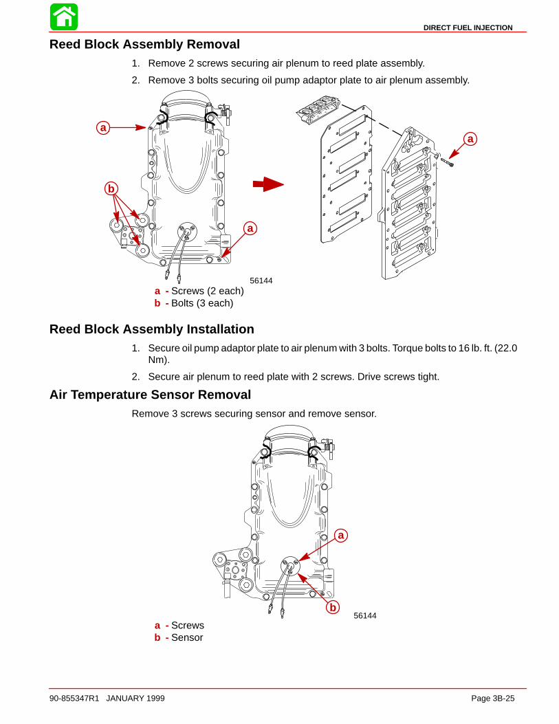
DIRECT FUEL INJECTION
90-855347R1 JANUARY 1999 Page 3B-25
Reed Block Assembly Removal1. Remove 2 screws securing air plenum to reed plate assembly.
2. Remove 3 bolts securing oil pump adaptor plate to air plenum assembly.
56144
b
a
a
a
a
b
aa
a - Screws (2 each)b - Bolts (3 each)
Reed Block Assembly Installation1. Secure oil pump adaptor plate to air plenum with 3 bolts. Torque bolts to 16 lb. ft. (22.0
Nm).
2. Secure air plenum to reed plate with 2 screws. Drive screws tight.
Air Temperature Sensor RemovalRemove 3 screws securing sensor and remove sensor.
56144
a
b
a
b
a - Screwsb - Sensor
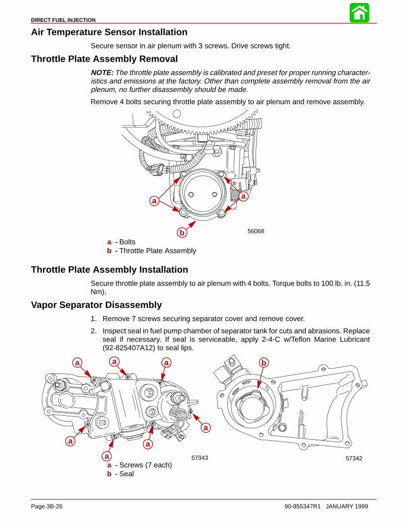
DIRECT FUEL INJECTION
Page 3B-26 90-855347R1 JANUARY 1999
Air Temperature Sensor InstallationSecure sensor in air plenum with 3 screws. Drive screws tight.
Throttle Plate Assembly RemovalNOTE: The throttle plate assembly is calibrated and preset for proper running character-istics and emissions at the factory. Other than complete assembly removal from the airplenum, no further disassembly should be made.
Remove 4 bolts securing throttle plate assembly to air plenum and remove assembly.
56068b
aaa
b
a
a - Boltsb - Throttle Plate Assembly
Throttle Plate Assembly InstallationSecure throttle plate assembly to air plenum with 4 bolts. Torque bolts to 100 lb. in. (11.5Nm).
Vapor Separator Disassembly1. Remove 7 screws securing separator cover and remove cover.
2. Inspect seal in fuel pump chamber of separator tank for cuts and abrasions. Replaceseal if necessary. If seal is serviceable, apply 2-4-C w/Teflon Marine Lubricant(92-825407A12) to seal lips.
b
57342
aaa
a
a
a
a
57343a - Screws (7 each)b - Seal

DIRECT FUEL INJECTION
90-855347R1 JANUARY 1999 Page 3B-27
3. Fuel pump may be removed from cover by wiggling slightly while pulling outward.
IMPORTANT: DO NOT twist pump during removal as wire harness may be dam-aged.
4. Disconnect harness from pump to separate pump from cover. Inspect filter screen fordebris. Screen may be pried out of pump and cleaned as required.
5. Inspect seal above fuel pump for cuts or abrasions. Replace seal if necessary. Apply2-4-C w/Teflon to seal lips.
5605856057
cb
cb a
d
a - Filter Screenb - Harness Connectorc - Pumpd - Seal (Seal shoulder faces OUT)
6. Loosen screw securing float assembly and remove float. Inspect float for deteriorationor fuel retention. Replace float as required.
7. Remove phenolic sealing plate and inspect imbedded neoprene seal on both sidesof plate for cuts or abrasions. Replace plate/seal assembly as required.
56059
ac
d
56058
baa
b
a - Screwb - Floatc - Plated - Seal
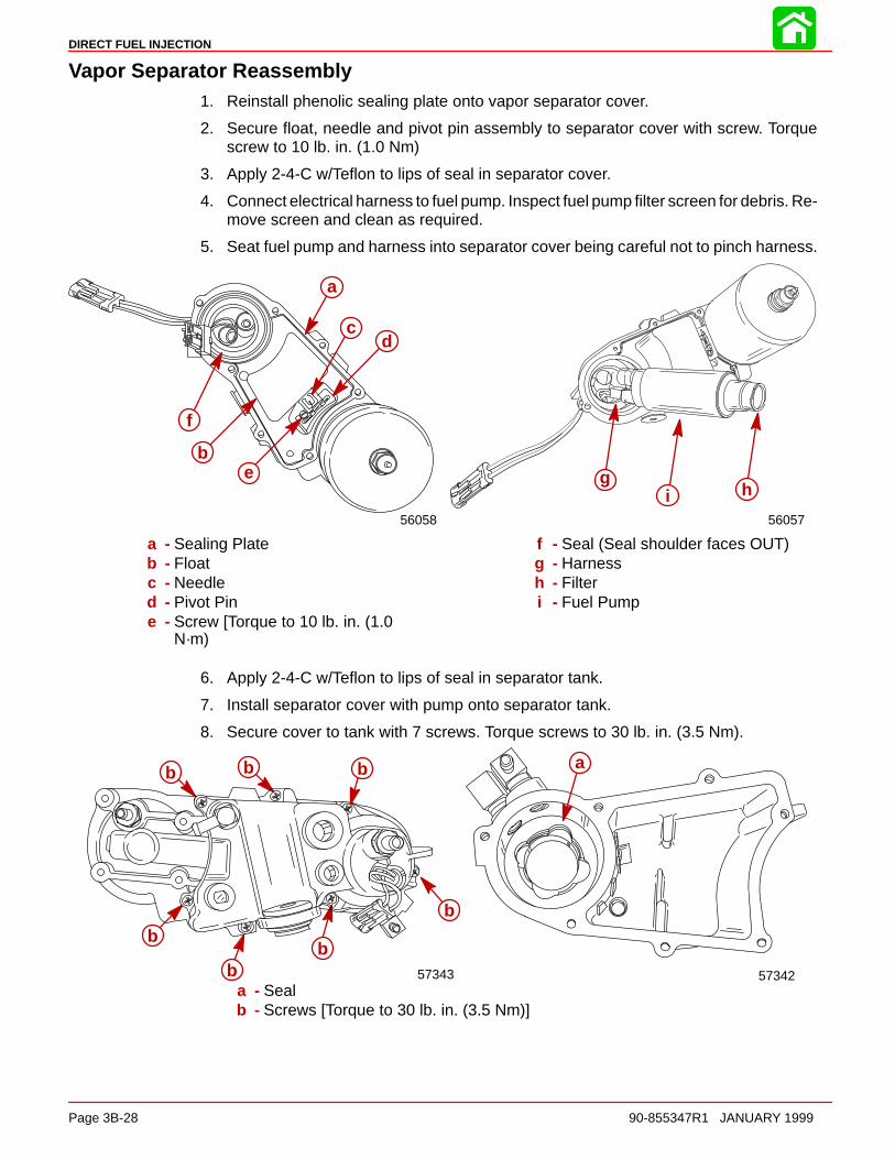
DIRECT FUEL INJECTION
Page 3B-28 90-855347R1 JANUARY 1999
Vapor Separator Reassembly1. Reinstall phenolic sealing plate onto vapor separator cover.
2. Secure float, needle and pivot pin assembly to separator cover with screw. Torquescrew to 10 lb. in. (1.0 Nm)
3. Apply 2-4-C w/Teflon to lips of seal in separator cover.
4. Connect electrical harness to fuel pump. Inspect fuel pump filter screen for debris. Re-move screen and clean as required.
5. Seat fuel pump and harness into separator cover being careful not to pinch harness.
56057
cag hi
56058
be
d
a
c
f
a
b
cd
e
a - Sealing Plateb - Floatc - Needled - Pivot Pine - Screw [Torque to 10 lb. in. (1.0
N·m)
f - Seal (Seal shoulder faces OUT)g - Harnessh - Filteri - Fuel Pump
6. Apply 2-4-C w/Teflon to lips of seal in separator tank.
7. Install separator cover with pump onto separator tank.
8. Secure cover to tank with 7 screws. Torque screws to 30 lb. in. (3.5 Nm).
5734257343
ab
b
bb
b
b b
a - Sealb - Screws [Torque to 30 lb. in. (3.5 Nm)]
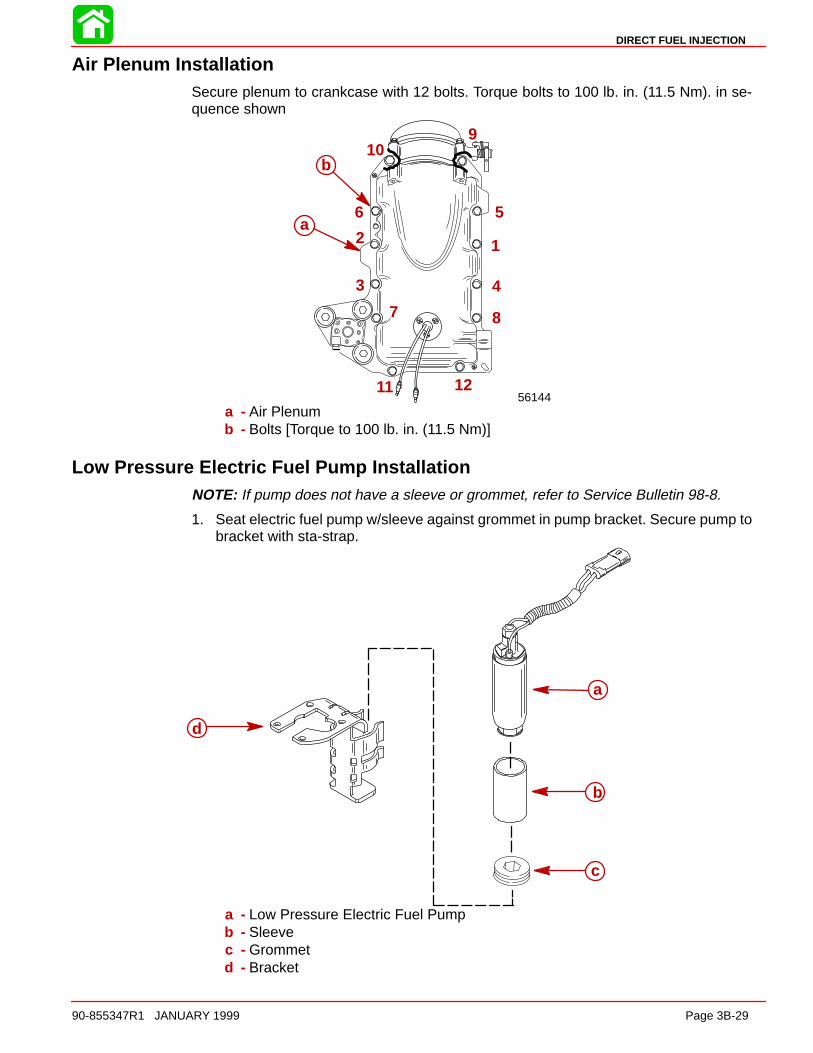
DIRECT FUEL INJECTION
90-855347R1 JANUARY 1999 Page 3B-29
Air Plenum InstallationSecure plenum to crankcase with 12 bolts. Torque bolts to 100 lb. in. (11.5 Nm). in se-quence shown
56144
a12
3 4
56
7 8
910
11 12
b
a
b
a - Air Plenumb - Bolts [Torque to 100 lb. in. (11.5 Nm)]
Low Pressure Electric Fuel Pump InstallationNOTE: If pump does not have a sleeve or grommet, refer to Service Bulletin 98-8.
1. Seat electric fuel pump w/sleeve against grommet in pump bracket. Secure pump tobracket with sta-strap.
d
a
b
c
a - Low Pressure Electric Fuel Pumpb - Sleevec - Grommetd - Bracket
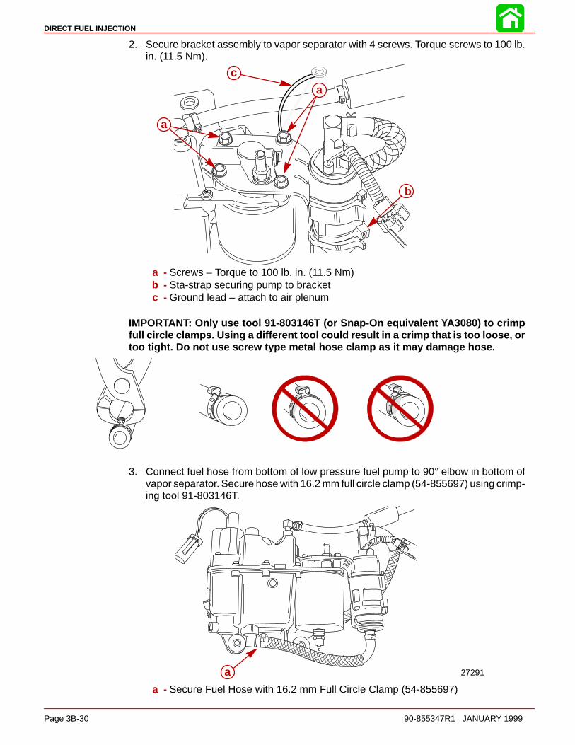
DIRECT FUEL INJECTION
Page 3B-30 90-855347R1 JANUARY 1999
2. Secure bracket assembly to vapor separator with 4 screws. Torque screws to 100 lb.in. (11.5 Nm).
a
a
b
c
a - Screws – Torque to 100 lb. in. (11.5 Nm)b - Sta-strap securing pump to bracketc - Ground lead – attach to air plenum
IMPORTANT: Only use tool 91-803146T (or Snap-On equivalent YA3080) to crimpfull circle clamps. Using a different tool could result in a crimp that is too loose, ortoo tight. Do not use screw type metal hose clamp as it may damage hose.
3. Connect fuel hose from bottom of low pressure fuel pump to 90° elbow in bottom ofvapor separator. Secure hose with 16.2 mm full circle clamp (54-855697) using crimp-ing tool 91-803146T.
a 27291
a - Secure Fuel Hose with 16.2 mm Full Circle Clamp (54-855697)

DIRECT FUEL INJECTION
90-855347R1 JANUARY 1999 Page 3B-31
4. Connect fuel hose from top of low pressure fuel pump to 90° elbow on back side ofvapor separator. Secure hose with 15.3 mm full circle clamp (54-856880) using crimp-ing tool 91-803146T. (Back view of vapor separator shown below)
a
57293
a - Secure Fuel Hose with 15.3 mm Full Circle Clamp (54-856880)
Vapor Separator Installation1. Secure vapor separator to air plenum with 3 bolts. Torque bolts to 45 lb. in. (5.0 Nm).
2. Connect fuel inlet hose from pulse pump.
3. Connect fuel outlet hose and fuel return hose to vapor separator.
a
b
e
f
d
c
57317a - Mounting Bolts [Torque to 45 lb. in. (5.0 Nm)b - Fuel Inlet Hosec - Fuel Outlet Hosed - Fuel Return Hosee - Low Pressure Electric Fuel Pump (6 - 9 psi)f - Inlet Fuel Hose to Low Pressure Pump

DIRECT FUEL INJECTION
Page 3B-32 90-855347R1 JANUARY 1999
4. Connect water separator sensor lead to water separator.
a
57317a - Sensor Lead
5. Connect electric fuel pump harness.
6. Connect vapor separator vent hose to air plenum.
7. Secure air temperature sensor leads to fuel hose with sta-strap.
56157
c
b
a
d
a
b
c
d
a - Electric Fuel Pump Harness Connectorb - Sta-Strapc - Top Fuel Hose (Fuel return from fuel cooler)d - Bottom Fuel Hose (Inlet from low pressure pump)
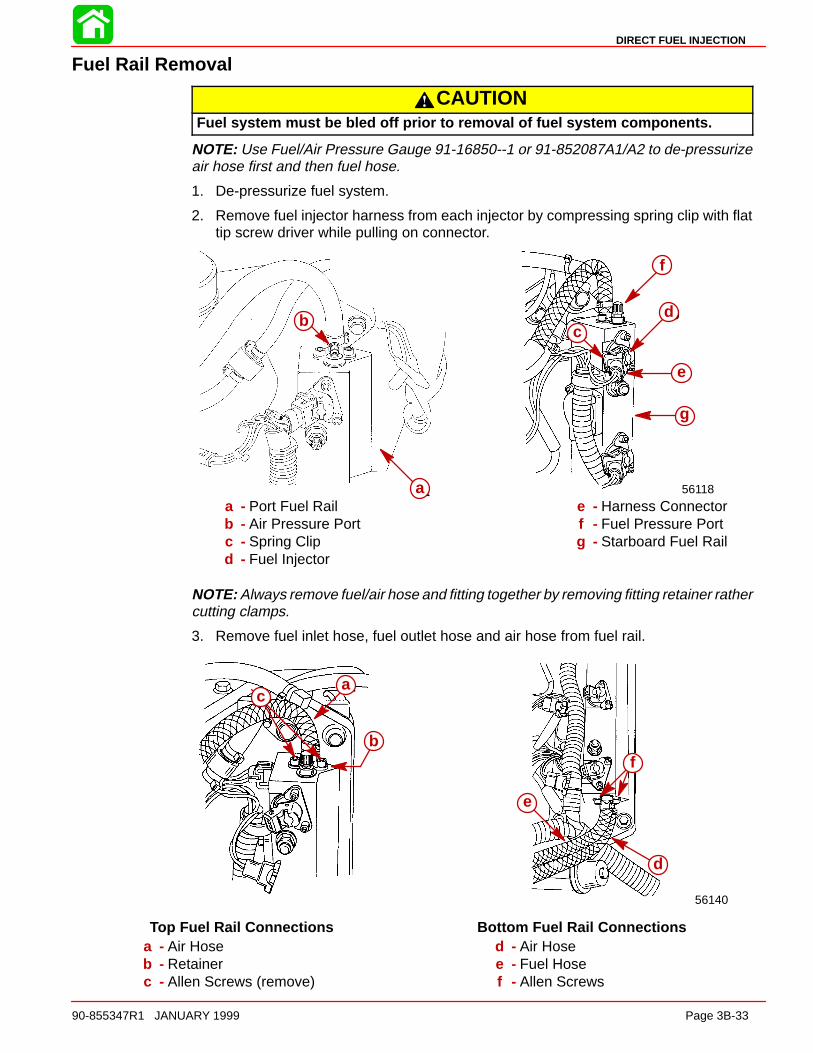
DIRECT FUEL INJECTION
90-855347R1 JANUARY 1999 Page 3B-33
Fuel Rail Removal
CAUTIONFuel system must be bled off prior to removal of fuel system components.
NOTE: Use Fuel/Air Pressure Gauge 91-16850--1 or 91-852087A1/A2 to de-pressurizeair hose first and then fuel hose.
1. De-pressurize fuel system.
2. Remove fuel injector harness from each injector by compressing spring clip with flattip screw driver while pulling on connector.
c
ba
56118
cd
e
aa
f
g
bb
a - Port Fuel Railb - Air Pressure Portc - Spring Clipd - Fuel Injector
e - Harness Connectorf - Fuel Pressure Portg - Starboard Fuel Rail
NOTE: Always remove fuel/air hose and fitting together by removing fitting retainer rathercutting clamps.
3. Remove fuel inlet hose, fuel outlet hose and air hose from fuel rail.
56140
c
d
e
f
ca
b
a
b
c
Top Fuel Rail Connections Bottom Fuel Rail Connectionsa - Air Hoseb - Retainerc - Allen Screws (remove)
d - Air Hosee - Fuel Hosef - Allen Screws
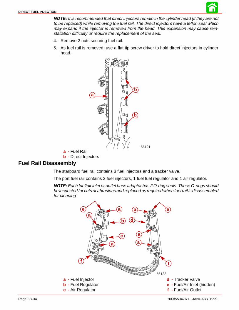
DIRECT FUEL INJECTION
Page 3B-34 90-855347R1 JANUARY 1999
NOTE: It is recommended that direct injectors remain in the cylinder head (if they are notto be replaced) while removing the fuel rail. The direct injectors have a teflon seal whichmay expand if the injector is removed from the head. This expansion may cause rein-stallation difficulty or require the replacement of the seal.
4. Remove 2 nuts securing fuel rail.
5. As fuel rail is removed, use a flat tip screw driver to hold direct injectors in cylinderhead.
56121
ab
b
ab
b
a - Fuel Railb - Direct Injectors
Fuel Rail DisassemblyThe starboard fuel rail contains 3 fuel injectors and a tracker valve.
The port fuel rail contains 3 fuel injectors, 1 fuel fuel regulator and 1 air regulator.
NOTE: Each fuel/air inlet or outlet hose adaptor has 2 O-ring seals. These O-rings shouldbe inspected for cuts or abrasions and replaced as required when fuel rail is disassembledfor cleaning.
56122
aa
a
a
a
a
b
c
da
b
c
d
a
a a
a
ae e
f f
a - Fuel Injectorb - Fuel Regulatorc - Air Regulator
d - Tracker Valvee - Fuel/Air Inlet (hidden)f - Fuel/Air Outlet
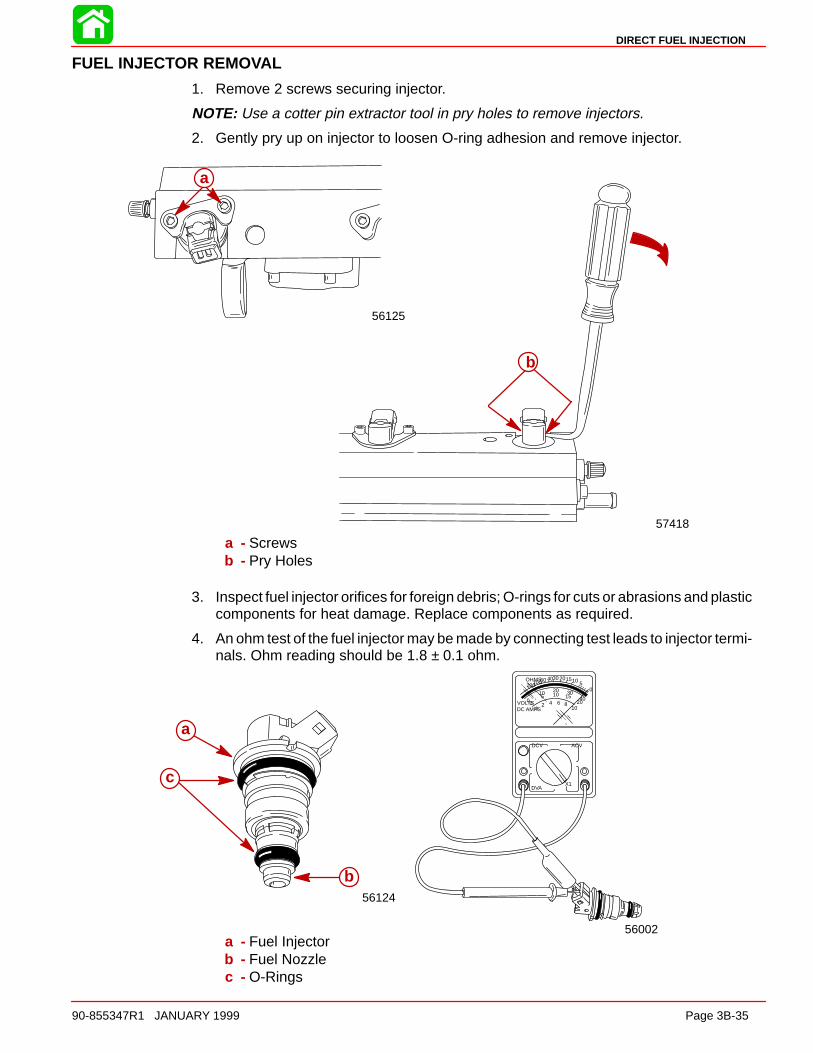
DIRECT FUEL INJECTION
90-855347R1 JANUARY 1999 Page 3B-35
FUEL INJECTOR REMOVAL
1. Remove 2 screws securing injector.
NOTE: Use a cotter pin extractor tool in pry holes to remove injectors.
2. Gently pry up on injector to loosen O-ring adhesion and remove injector.
56125
aa
b
57418
a - Screwsb - Pry Holes
3. Inspect fuel injector orifices for foreign debris; O-rings for cuts or abrasions and plasticcomponents for heat damage. Replace components as required.
4. An ohm test of the fuel injector may be made by connecting test leads to injector termi-nals. Ohm reading should be 1.8 ± 0.1 ohm.
VOLTSDC AMPS
OHMS
02 4 6 8
10
DCV ACV
DVA
005
10 2010 30
15 4020
05101520304060100200
X1
56002
56124
a
b
c
a
b
c
a - Fuel Injectorb - Fuel Nozzlec - O-Rings

DIRECT FUEL INJECTION
Page 3B-36 90-855347R1 JANUARY 1999
FUEL INJECTOR INSTALLATION
NOTE: Apply anti-seize grease (obtain locally) or 2-4-C w/Teflon to fuel injector attachingscrew threads.
1. Insert fuel injector into fuel rail with connector pins facing (inwards) towards center ofengine.
NOTE: Turn injector back-and-forth slightly to seat injector O-rings in fuel rail while secur-ing injector with retainer and 2 screws. Torque screws to 70 lb. in. (8.0 Nm).
56125
c
a
b
a - Injectorb - Retainerc - Screws [Torque to 70 lb. in. (8.0 Nm)]

DIRECT FUEL INJECTION
90-855347R1 JANUARY 1999 Page 3B-37
Fuel Pressure RegulatorRegulator Closed Regulator Open
ÇÇ ÇÇ ÇÇ ÇÇ
1
23
4
5
67
8
9
10
11
12
13
1
23
4
5
67
8
9
10
11
1
23
4
5
67
8
9
10
11
12
13
1
23
4
5
67
8
9
10
11
12
13
1 - Top Cover2 - Expansion Plug3 - O-ring4 - Spring Retainer5 - Spring6 - O-ring7 - Diaphragm Seat
8 - Air Rail9 - Air Passage (from Air Compressor)
10 - Fuel Return Passage (to Vapor Separator)11 - Fuel Inlet Passage (from Electric Fuel Pump)12 - Diaphragm Assembly13 - Calibration Screw (Do Not Turn)
The fuel pump is capable of delivering more fuel than the engine can consume. Excessfuel flows through the fuel pressure regulator, interconnecting passages/hoses, fuel cool-er, and back to the vapor separator tank. This constant flow of fuel means that the fuelsystem is always supplied with cool fuel, thereby preventing the formation of fuel vaporbubbles and minimizing the chances of vapor lock.
The fuel pressure regulator is calibrated to raise the fuel pressure to 10 psi above the airpressure.
The fuel regulator is mounted on the port fuel rail, near the top. This regulator relies onboth air and spring pressure to control the fuel pressure. Inside the regulator assemblyis a 10 lb. spring, this spring holds the diaphragm against the diaphragm seat. The contactbetween the diaphragm and diaphragm seat closes the passage between the incomingfuel (from the electric fuel pump) and the fuel return passage.
When the engine is not running (no air pressure on the spring side of the diaphragm) thefuel pressure required to move the diaphragm is 10 psi.
When the engine is running, air pressure from the air compressor (80 psi) is routedthrough the air passages, to the spring side of the fuel pressure regulator diaphragm.
The air pressure (80 psi) and spring pressure (10 psi) combine to regulate system fuelpressure to 90 psi - or 10 psi higher than the air pressure in the DFI system fuel/air rails.

DIRECT FUEL INJECTION
Page 3B-38 90-855347R1 JANUARY 1999
FUEL REGULATOR REMOVAL
1. Remove 4 screws securing regulator and remove regulator.
2. Inspect regulator diaphragm for cuts or tears.
3. Inspect regulator housing O-ring for cuts and abrasions. Replace components as re-quired.
56127
dbcac
de f
56126
a
b
a
b
a
a - Screwsb - Fuel Regulatorc - Diaphragmd - Springe - Cupf - O-Ring
FUEL REGULATOR INSTALLATION
NOTE: Apply a light coat of 2-4-C w/Teflon to diaphragm surface and O-ring to aid in theretention of diaphragm and O-ring on fuel rail during reassembly.
1. Position diaphragm on fuel rail.
2. Position O-ring on fuel rail.
3. Position spring and cup onto diaphragm.
NOTE: Apply anti-seize grease (obtain locally) or 2-4-C w/Teflon to regulator attachingscrew threads.
4. Place cover over spring/cup/diaphragm assembly and secure with 4 screws. Torquescrews to 70 lb. in. (8.0 Nm).
56126
a ae e
56128
a
c
d
b ab
c
d
a - Diaphragmb - O-Ringc - Springd - Cupe - Screws [Torque to 70 lb. in. (8.0 Nm)]
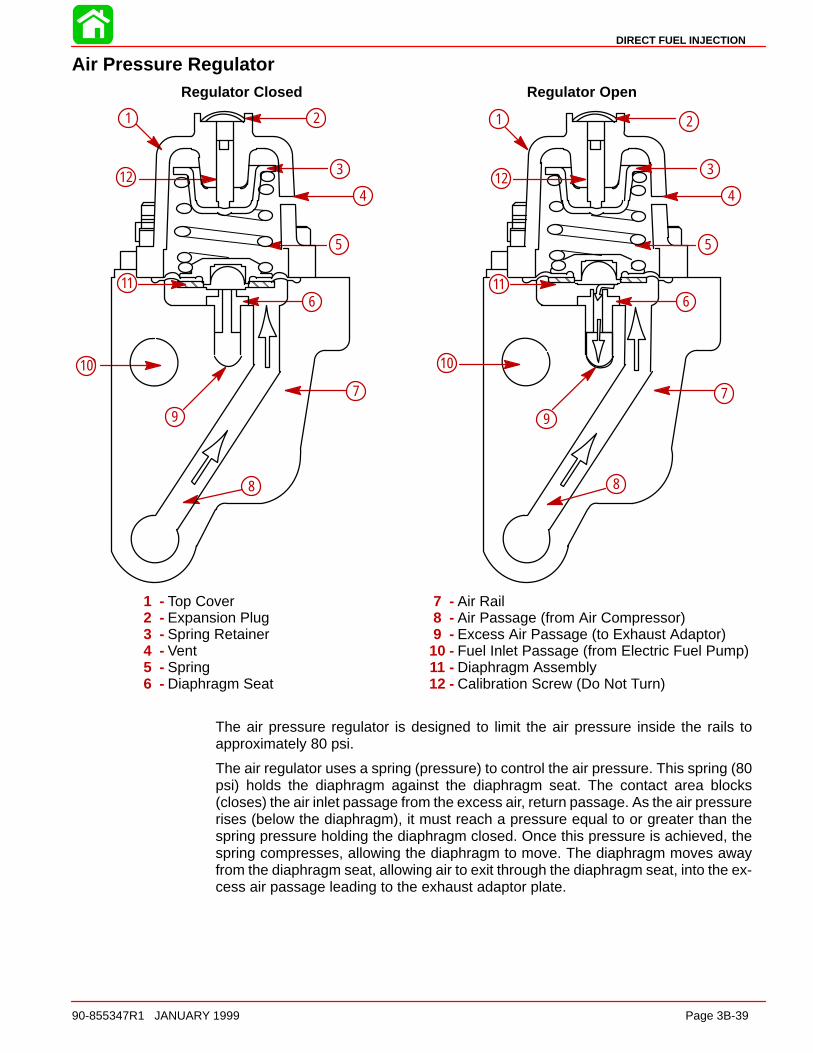
DIRECT FUEL INJECTION
90-855347R1 JANUARY 1999 Page 3B-39
Air Pressure RegulatorRegulator Closed Regulator Open
ÇÇÇ ÇÇÇÇÇÇ
ÇÇÇÇ
1 2
3
4
5
6
7
8
9
10
12
11
1
12
10
9
8
7
6
5
4
3
2
11
1 2
3
4
5
6
7
8
9
10
11
12
1 2
3
4
5
6
7
8
9
10
11
12
1 - Top Cover2 - Expansion Plug3 - Spring Retainer4 - Vent5 - Spring6 - Diaphragm Seat
7 - Air Rail8 - Air Passage (from Air Compressor)9 - Excess Air Passage (to Exhaust Adaptor)
10 - Fuel Inlet Passage (from Electric Fuel Pump)11 - Diaphragm Assembly12 - Calibration Screw (Do Not Turn)
The air pressure regulator is designed to limit the air pressure inside the rails toapproximately 80 psi.
The air regulator uses a spring (pressure) to control the air pressure. This spring (80psi) holds the diaphragm against the diaphragm seat. The contact area blocks(closes) the air inlet passage from the excess air, return passage. As the air pressurerises (below the diaphragm), it must reach a pressure equal to or greater than thespring pressure holding the diaphragm closed. Once this pressure is achieved, thespring compresses, allowing the diaphragm to move. The diaphragm moves awayfrom the diaphragm seat, allowing air to exit through the diaphragm seat, into the ex-cess air passage leading to the exhaust adaptor plate.

DIRECT FUEL INJECTION
Page 3B-40 90-855347R1 JANUARY 1999
AIR REGULATOR REMOVAL
1. Remove 4 screws securing regulator and remove regulator.
2. Inspect regulator diaphragm for cuts or tears. Replace as required.
56130
a
b
c
c
d
e
56129b
aaa a
b
a - Screwsb - Air Regulatorc - Diaphragmd - Springe - Cup
AIR REGULATOR INSTALLATION
NOTE: Apply a light coat of 2-4-C w/Teflon to diaphragm surface to aid in the retentionof diaphragm on fuel rail during reassembly.
1. Position diaphragm, spring and cup onto fuel rail with fuel rail in horizontal position.
NOTE: Apply anti-seize grease (obtain locally) or 2-4-C w/Teflon to regulator attachingscrew threads.
NOTE: Due to the stiffness of the regulator spring, it is recommended that 2 longer screws(5mm x 25mm long) (10-40073 25) and 2 flat washers (12-30164) be installed throughcover first to begin compression. This will allow 2 shorter screws (5mm x 15mm long) tobe installed. Remove 2 long screws w/flat washers and install remaining 2 short screws(5mm x 15mm). Torque screws to 70 lb. in. (8.0 Nm).
56132
a
c b bc
d
e ef f
56131
c
b
aa
b
c
a - Cupb - Springc - Diaphragmd - Covere - Screws (5mm x 25mm) (10-40073 25)f - Flat Washers (12-30164)

DIRECT FUEL INJECTION
90-855347R1 JANUARY 1999 Page 3B-41
Tracker ValveEngine Off (No Pressure) Engine at Operating Pressures
12 3
4
5
6
7
8
12 3
4
5
68
99
12 3
4
5
6
7
8
9
12
3
4
5
6
7
8
9
1 - Top Cover2 - Spring Retainer (not shown)3 - Spring4 - O-ring5 - Diaphragm (at rest) Seat
6 - Air Rail7 - Air Passage (from Air Compressor)8 - Fuel Inlet Passage (from Electric
Fuel Pump)9 - Diaphragm Assembly
The tracker is located on the starboard fuel/air rail assembly. The DFI system must main-tain a constant 10 psi pressure difference between the fuel pressure and air pressure inthe rails, at all times. The tracker is designed to maintain the 10 psi differential when theair or fuel pressure suddenly raises (i.e. pulses generated by the compressor’s piston orby the fuel injectors opening and closing). The tracker contains a spring on the air sideof the diaphragm. This spring positions the diaphragm against the diaphragm’s seat(when the engine is not running).
After the engine starts, and the fuel and air pressure reach normal operating range, thefuel pressure will compress the spring and the diaphragm will move slightly away from theseat (to a neutral position). At this point the pressure on both sides of the tracker dia-phragm is equal (10 psi spring pressure + 80 psi air pressure = 90 psi fuel pressure).
Any air or fuel pressure “spikes” on one side of the diaphragm will transfer this pressurerise to the other system (air or fuel) on the other side of the diaphragm. Both systems willhave a momentary increase in pressure so that the 10 psi difference between air and fuelsystem pressures can be maintained.
NOTE: To prevent excessive wear in the seat, the tracker is calibrated to allow the dia-phragm to be slightly away from the seat during normal operation.

DIRECT FUEL INJECTION
Page 3B-42 90-855347R1 JANUARY 1999
TRACKER VALVE REMOVAL
1. Remove 4 screws securing tracker valve and remove tracker assembly.
2. Inspect tracker diaphragm for cuts and tears.
3. Inspect tracker cover O-ring for cuts and abrasions. Replace components as re-quired.
56136
a
b
c
b
c
d
56135a
aa
a
a - Screwsb - Diaphragmc - Springd - O-ring
TRACKER VALVE INSTALLATION
NOTE: Apply a light coat of 2-4-C w/Teflon to tracker diaphragm and cover O-ring to aidin their retention on fuel rail while reinstalling tracker valve to fuel rail.
NOTE: Apply anti-seize grease (obtain locally) or 2-4-C w/Teflon to tracker valve attach-ing screw threads.
1. Position diaphragm, spring and O-ring onto fuel rail.
2. Place cover over diaphragm/spring/O-ring assembly and secure with 4 screws.Torque screws to 70 lb. in. (8.0 Nm).
56135
a
b
b
cb
a56137
d
e
ea
bc
a - Diaphragmb - Springc - O-ringd - Covere - Screws [Torque to 70 lb. in. (8.0 Nm)]
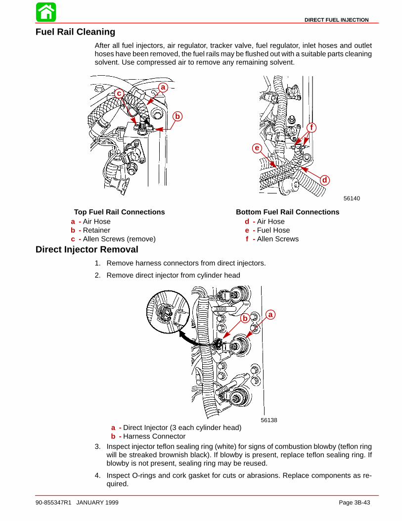
DIRECT FUEL INJECTION
90-855347R1 JANUARY 1999 Page 3B-43
Fuel Rail CleaningAfter all fuel injectors, air regulator, tracker valve, fuel regulator, inlet hoses and outlethoses have been removed, the fuel rails may be flushed out with a suitable parts cleaningsolvent. Use compressed air to remove any remaining solvent.
56140
c
d
e
f
ca
b
a
b
c
Top Fuel Rail Connections Bottom Fuel Rail Connectionsa - Air Hoseb - Retainerc - Allen Screws (remove)
d - Air Hosee - Fuel Hosef - Allen Screws
Direct Injector Removal1. Remove harness connectors from direct injectors.
2. Remove direct injector from cylinder head
56138
ab ab
a - Direct Injector (3 each cylinder head)b - Harness Connector
3. Inspect injector teflon sealing ring (white) for signs of combustion blowby (teflon ringwill be streaked brownish black). If blowby is present, replace teflon sealing ring. Ifblowby is not present, sealing ring may be reused.
4. Inspect O-rings and cork gasket for cuts or abrasions. Replace components as re-quired.
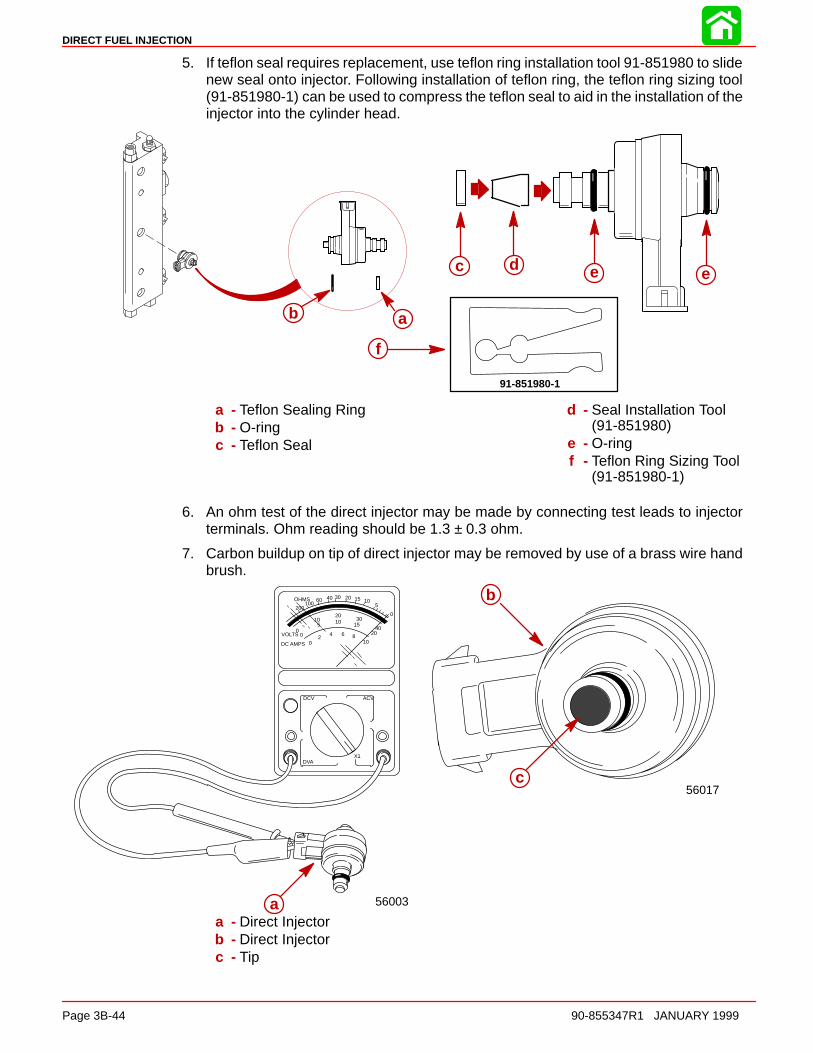
DIRECT FUEL INJECTION
Page 3B-44 90-855347R1 JANUARY 1999
5. If teflon seal requires replacement, use teflon ring installation tool 91-851980 to slidenew seal onto injector. Following installation of teflon ring, the teflon ring sizing tool(91-851980-1) can be used to compress the teflon seal to aid in the installation of theinjector into the cylinder head.
d
aab
c e e
91-851980-1
f
a - Teflon Sealing Ringb - O-ringc - Teflon Seal
d - Seal Installation Tool(91-851980)
e - O-ringf - Teflon Ring Sizing Tool
(91-851980-1)
6. An ohm test of the direct injector may be made by connecting test leads to injectorterminals. Ohm reading should be 1.3 ± 0.3 ohm.
7. Carbon buildup on tip of direct injector may be removed by use of a brass wire handbrush.
56017
a
b
b
c
VOLTS
DC AMPS
OHMS
02
4 6 810
DCV ACV
DVA
00
510
2010 30
1540
20
0
5101520304060
100200
X1
56003aaa - Direct Injectorb - Direct Injectorc - Tip
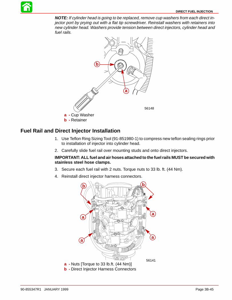
DIRECT FUEL INJECTION
90-855347R1 JANUARY 1999 Page 3B-45
NOTE: If cylinder head is going to be replaced, remove cup washers from each direct in-jector port by prying out with a flat tip screwdriver. Reinstall washers with retainers intonew cylinder head. Washers provide tension between direct injectors, cylinder head andfuel rails.
56148
b
aa
b
a - Cup Washerb - Retainer
Fuel Rail and Direct Injector Installation1. Use Teflon Ring Sizing Tool (91-851980-1) to compress new teflon sealing rings prior
to installation of injector into cylinder head.
2. Carefully slide fuel rail over mounting studs and onto direct injectors.
IMPORTANT: ALL fuel and air hoses attached to the fuel rails MUST be secured withstainless steel hose clamps.
3. Secure each fuel rail with 2 nuts. Torque nuts to 33 lb. ft. (44 Nm).
4. Reinstall direct injector harness connectors.
56141
b
a
aa
a
b
a
a
a
a
b b
a - Nuts [Torque to 33 lb.ft. (44 Nm)]b - Direct Injector Harness Connectors

DIRECT FUEL INJECTION
Page 3B-46 90-855347R1 JANUARY 1999
Air CompressorAir compressor is a single cylinder, water cooled and lubricated by the outboard oil pump.
Air Compressor Specifications
Air Compressor Type
Compressor Output
Reciprocating Piston(1 to 1 ratio with engine RPM)
@ Idle – 80 psi@ W.O.T. – 110 psi
Cylinder Block Displacement 7.07 cu. in. (116 cc)
Cylinder Bore Diameter (Standard)Taper/Out-of-Round/Wear Maxi-mumBore Type
2.5591 in. (65.0 mm)
0.001 in. (0.025 mm)Cast Iron
Stroke Length 1.374 in. (34.9 mm)
Piston Piston Type Aluminum
Piston Diameter
Dimen-sion “A”at RightAngle(90°) toPistonPin 0.500 in.
2.5578 ± .0004 in.(64.97 ± 0.010 mm)
Piston Ring End GapTop Ring
Middle Ring
Bottom Ring
0.0059 – 0.0098 in.(0.15 – 0.25 mm)
0.0059 – 0.0098 in.(0.15 – 0.25 mm)0.0039 – 0.014 in.(0.10 – 0.35 mm)
Reeds Reed Stand Open 0.010 in. (0.25 mm)

DIRECT FUEL INJECTION
90-855347R1 JANUARY 1999 Page 3B-47
COMPRESSOR REMOVAL
1. Disconnect battery cables from battery terminals.
2. Remove top cowling.
IMPORTANT: Prior to removing flywheel cover, remove vent hose from fitting onflywheel cover.
3. Remove flywheel cover.
4. Use 3/8 inch (9.5 mm) drive on belt tensioner arm to relieve belt tension. Remove belt.
b
a
56142
a
b
a - Belt Tensionerb - 3/8 in. (9.5 mm) drive
CAUTIONIf engine has been recently run, air pressure outlet hose fittings may be extremelyhot. Allow components to cool off before beginning disassembly.
5. Disconnect air pressure outlet hose.
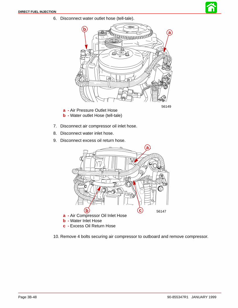
DIRECT FUEL INJECTION
Page 3B-48 90-855347R1 JANUARY 1999
6. Disconnect water outlet hose (tell-tale).
56149
aba
b
a - Air Pressure Outlet Hoseb - Water outlet Hose (tell-tale)
7. Disconnect air compressor oil inlet hose.
8. Disconnect water inlet hose.
9. Disconnect excess oil return hose.
56147
a
b c
a
b ca - Air Compressor Oil Inlet Hoseb - Water Inlet Hosec - Excess Oil Return Hose
10. Remove 4 bolts securing air compressor to outboard and remove compressor.
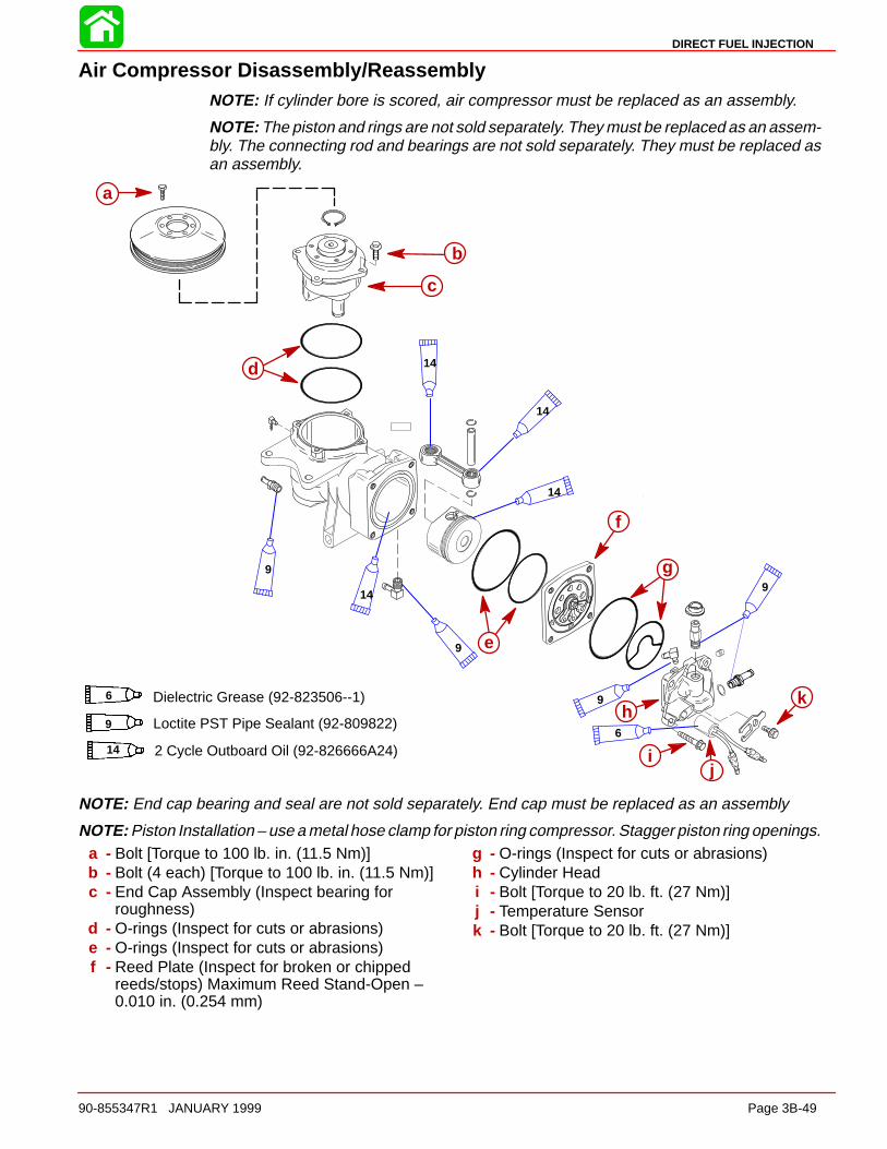
DIRECT FUEL INJECTION
90-855347R1 JANUARY 1999 Page 3B-49
Air Compressor Disassembly/ReassemblyNOTE: If cylinder bore is scored, air compressor must be replaced as an assembly.
NOTE: The piston and rings are not sold separately. They must be replaced as an assem-bly. The connecting rod and bearings are not sold separately. They must be replaced asan assembly.
ÇÇÇÇÇÇÇÇÇ
a
b
c
d
e
f
g
ij
k
9
14
9
14
14
14
9
9
6
hDielectric Grease (92-823506--1)6
Loctite PST Pipe Sealant (92-809822)9
14 2 Cycle Outboard Oil (92-826666A24)
NOTE: End cap bearing and seal are not sold separately. End cap must be replaced as an assembly
NOTE: Piston Installation – use a metal hose clamp for piston ring compressor. Stagger piston ring openings.a - Bolt [Torque to 100 lb. in. (11.5 Nm)]b - Bolt (4 each) [Torque to 100 lb. in. (11.5 Nm)]c - End Cap Assembly (Inspect bearing for
roughness)d - O-rings (Inspect for cuts or abrasions)e - O-rings (Inspect for cuts or abrasions)f - Reed Plate (Inspect for broken or chipped
reeds/stops) Maximum Reed Stand-Open –0.010 in. (0.254 mm)
g - O-rings (Inspect for cuts or abrasions)h - Cylinder Headi - Bolt [Torque to 20 lb. ft. (27 Nm)]j - Temperature Sensork - Bolt [Torque to 20 lb. ft. (27 Nm)]
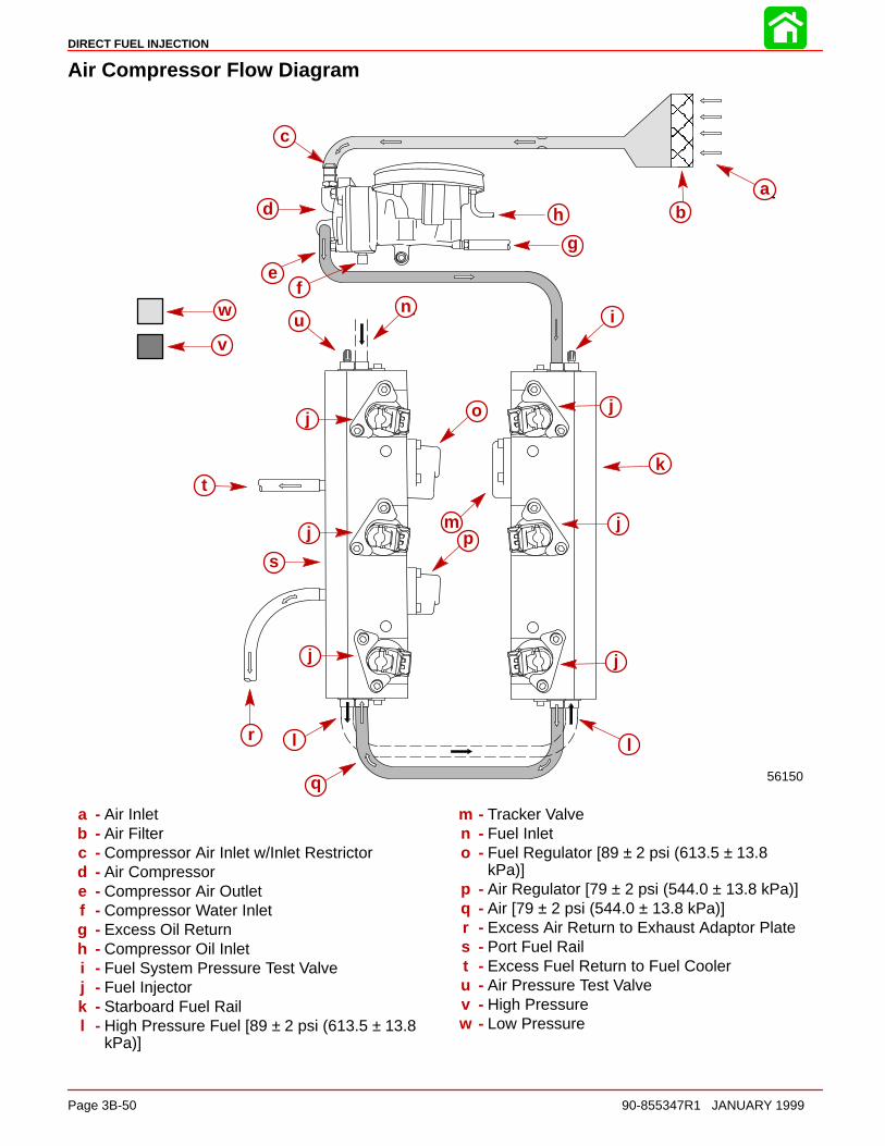
DIRECT FUEL INJECTION
Page 3B-50 90-855347R1 JANUARY 1999
Air Compressor Flow Diagram
ÎÎÎÎÎÎÎÎ
56150
ab
c
d
ef
g
h
i
j
k
l
m
n
o
p
q
r
s
t
u
v
j
jj
j
j
l
w
ab
c
d
ef
g
h
i
j
k
l
m
n
o
p
q
r
s
t
uv
w
j
jj
j
j
l
a - Air Inletb - Air Filterc - Compressor Air Inlet w/Inlet Restrictord - Air Compressore - Compressor Air Outletf - Compressor Water Inletg - Excess Oil Returnh - Compressor Oil Inleti - Fuel System Pressure Test Valvej - Fuel Injectork - Starboard Fuel Raill - High Pressure Fuel [89 ± 2 psi (613.5 ± 13.8
kPa)]
m - Tracker Valven - Fuel Inleto - Fuel Regulator [89 ± 2 psi (613.5 ± 13.8
kPa)]p - Air Regulator [79 ± 2 psi (544.0 ± 13.8 kPa)]q - Air [79 ± 2 psi (544.0 ± 13.8 kPa)]r - Excess Air Return to Exhaust Adaptor Plates - Port Fuel Railt - Excess Fuel Return to Fuel Cooleru - Air Pressure Test Valvev - High Pressurew - Low Pressure

DIRECT FUEL INJECTION
90-855347R1 JANUARY 1999 Page 3B-51
Air Compressor Pressure TestInstall Pressure Gauge Assembly 91-852087A1/A2 to fuel rail pressure test valves. Star-board rail has fuel pressure test valve. Port fuel rail has air pressure test valve.
NOTE: After 15 seconds of cranking engine with starter motor, air pressure gauge shouldindicate 79 ± 2 psi (544.0 ± 13.8 kPa) and fuel pressure gauge should indicate 89 ± 2 psi(613.5 ± 13.8 kPa).
56146
a b
c
d
a b
c
d
a - Air Pressure Gauge (Should Indicate 79 ± 2 psi (544.0 ± 13.8 kPa)b - Fuel Pressure Gauge (Should Indicate 89 ± 2 psi (613.5 ± 13.8 kPa)c - Fuel Pressure Test Valved - Air Pressure Test Valve
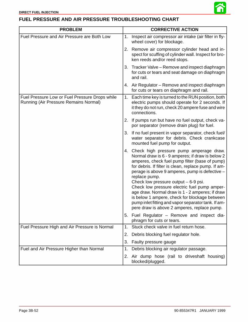
DIRECT FUEL INJECTION
Page 3B-52 90-855347R1 JANUARY 1999
FUEL PRESSURE AND AIR PRESSURE TROUBLESHOOTING CHART
PROBLEM CORRECTIVE ACTION
Fuel Pressure and Air Pressure are Both Low 1. Inspect air compressor air intake (air filter in fly-wheel cover) for blockage.
2. Remove air compressor cylinder head and in-spect for scuffing of cylinder wall. Inspect for bro-ken reeds and/or reed stops.
3. Tracker Valve – Remove and inspect diaphragmfor cuts or tears and seat damage on diaphragmand rail.
4. Air Regulator – Remove and inspect diaphragmfor cuts or tears on diaphragm and rail.
Fuel Pressure Low or Fuel Pressure Drops whileRunning (Air Pressure Remains Normal)
1. Each time key is turned to the RUN position, bothelectric pumps should operate for 2 seconds. Ifit they do not run, check 20 ampere fuse and wireconnections.
2. If pumps run but have no fuel output, check va-por separator (remove drain plug) for fuel.
3. If no fuel present in vapor separator, check fuel/water separator for debris. Check crankcasemounted fuel pump for output.
4. Check high pressure pump amperage draw.Normal draw is 6 - 9 amperes; if draw is below 2amperes, check fuel pump filter (base of pump)for debris. If filter is clean, replace pump. If am-perage is above 9 amperes, pump is defective –replace pump.Check low pressure output – 6-9 psi.Check low pressure electric fuel pump amper-age draw. Normal draw is 1 - 2 amperes; if drawis below 1 ampere, check for blockage betweenpump inlet fitting and vapor separator tank. If am-pere draw is above 2 amperes, replace pump.
5. Fuel Regulator – Remove and inspect dia-phragm for cuts or tears.
Fuel Pressure High and Air Pressure is Normal 1. Stuck check valve in fuel return hose.
2. Debris blocking fuel regulator hole.
3. Faulty pressure gauge
Fuel and Air Pressure Higher than Normal 1. Debris blocking air regulator passage.
2. Air dump hose (rail to driveshaft housing)blocked/plugged.

3C
OIL INJECTION
90-855347R1 JANUARY 1999 Page 3C-1
FUEL SYSTEMSection 3C – Oil Injection
Table of Contents
Oil System Operation 3C-1. . . . . . . . . . . . . . . . . . . . . . . . . Oil Pump Output 3C-1. . . . . . . . . . . . . . . . . . . . . . . . . . Oil System 3C-2. . . . . . . . . . . . . . . . . . . . . . . . . . . . . . . Oil Hose Check Valve Installation on 1998 Model135/150 DFI Outboards SN 0G886266 andBelow 3C-3. . . . . . . . . . . . . . . . . . . . . . . . . . . . . . . . . . . . Oil Injection Hose Installation 3C-9. . . . . . . . . . . . . . . Oil Pump Removal and Installation 3C-10. . . . . . . . Engine Oil Reservoir Removal and Installation 3C-11
Priming the Oil Pump 3C-12. . . . . . . . . . . . . . . . . . . . Priming Procedure – Method 1 3C-13. . . . . . . . . . . . Remote Oil Hose Connections 3C-14. . . . . . . . . . . . Filling the Oil Tanks 3C-14. . . . . . . . . . . . . . . . . . . . . . Purging Air From the Engine Oil Reservoirand Remote Oil Hose 3C-15. . . . . . . . . . . . . . . . . . . . Oil Warning Systems 3C-15. . . . . . . . . . . . . . . . . . . . .
Oil System Troubleshooting 3C-16. . . . . . . . . . . . . . . . . Low Oil Warning System is Activated 3C-16. . . . . .
Oil System Operation
Oil in this engine is not mixed with the fuel before entering the combustion chamber. Oilis stored inside the remote oil tank in the boat. Crankcase pressure forces oil from theremote oil tank into the engine oil reservoir. The engine oil reservoir feeds oil to the oilpump. The oil pump is ECM driven and controls oil distribution to the crankcase and aircompressor. The oil pump has seven oil discharge ports. Six of the oil discharge ports in-ject oil into the crankcase through hoses, one hose for each cylinder. The last oil dischargeport discharges oil into the air compressor for lubrication. Unused oil from the air compres-sor returns to the plenum and is ingested through the crankcase.
The ECM is programmed to automatically increase the oil supply to the engine during theinitial engine break-in period. The oil ratio is doubled during the first 120 minutes of opera-tion whenever engine speed exceeds 2500 RPM; below 2500 RPM the oil pump providesoil at the normal ratio. After the engine break-in period, the oil ratio will return to normal– 300 - 400:1 at idle to 60:1 at WOT.
NOTE: On some light boat applications after the break-in is completed and the engine isbeing run at cruising speed – between 4000 and 5000 RPM – the fuel to oil ratio may beas high as 28:1. This results from a reduced throttle opening with a corresponding reduc-tion in fuel consumption.
Oil Pump OutputUsing the DDT to activate auto prime, the oil pump should discharge 110 ml (cc) ± 8 ml(cc) during the auto prime time period.
To check the oil pump output:
• Verify the onboard oil reservoir is full.
• Release any pressure (loosen cap) from the remote oil tank in the boat.
• With engine not running, use the DDT to activate the auto prime.
• Using a ml or cc graduated container, record the amount of oil needed to refill the on-board oil reservoir.
• Retighten cap on the remote oil tank in the boat.

OIL INJECTION
Page 3C-2 90-855347R1 JANUARY 1999
Oil System
fh
a
b
c
d
e
g
i
a - Remote Oil Tankb - Engine Oil Reservoirc - Oil Supply Hose to the Oil Pumpd - Oil Pumpe - Oil Supply Hoses to the Cylinders (6)f - Oil Supply Hose to the Air Compressorg - Air Compressorh - Check Valvei - Oil Return Hose from the Air Compressor
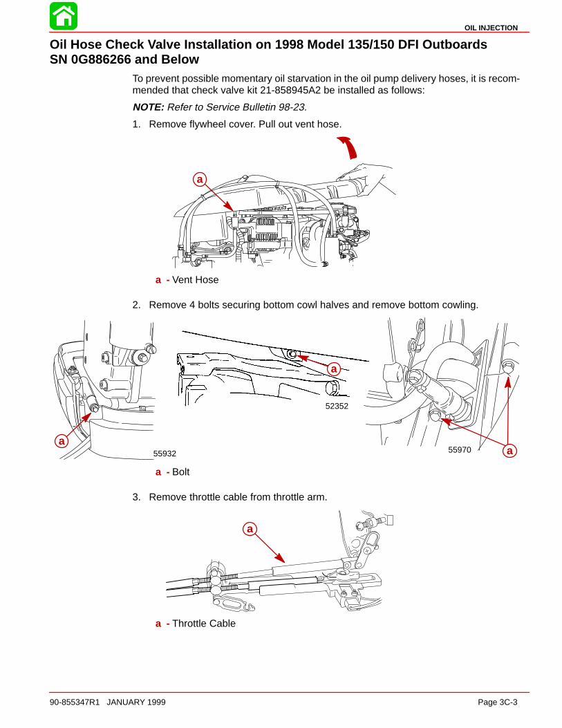
OIL INJECTION
90-855347R1 JANUARY 1999 Page 3C-3
Oil Hose Check Valve Installation on 1998 Model 135/150 DFI Outboards SN 0G886266 and Below
To prevent possible momentary oil starvation in the oil pump delivery hoses, it is recom-mended that check valve kit 21-858945A2 be installed as follows:
NOTE: Refer to Service Bulletin 98-23.
1. Remove flywheel cover. Pull out vent hose.
a
a - Vent Hose
2. Remove 4 bolts securing bottom cowl halves and remove bottom cowling.
55970
52352
55932a
a
a
a - Bolt
3. Remove throttle cable from throttle arm.
a
a - Throttle Cable
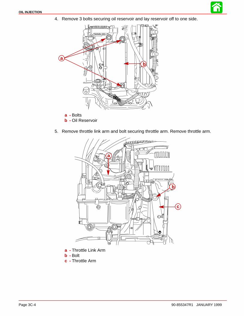
OIL INJECTION
Page 3C-4 90-855347R1 JANUARY 1999
4. Remove 3 bolts securing oil reservoir and lay reservoir off to one side.
ab
a - Boltsb - Oil Reservoir
5. Remove throttle link arm and bolt securing throttle arm. Remove throttle arm.
–
a
b
c
a - Throttle Link Armb - Boltc - Throttle Arm

OIL INJECTION
90-855347R1 JANUARY 1999 Page 3C-5
6. Remove alternator/air compressor belt.
7. Remove aft alternator bolt and pivot alternator forward.
a
b
c
d
a - Alternator/Air Compressor Beltb - Belt Tensioner (rotate counterclockwise)c - Aft Alternator Boltd - Alternator (rotate forward)
NOTE: It is recommended that a razor knife be used to make a small slit in the oil hosesto aid in removal. Removing hoses without cutting them may result in the breakage of theoil fitting. Trim cut portion off of oil hose before reinstalling hose.
8. Remove oil hoses from fittings on #2, #4, and #6 cylinders.
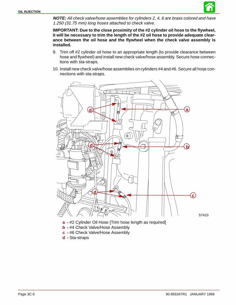
OIL INJECTION
Page 3C-6 90-855347R1 JANUARY 1999
NOTE: All check valve/hose assemblies for cylinders 2, 4, 6 are brass colored and have1.250 (31.75 mm) long hoses attached to check valve.
IMPORTANT: Due to the close proximity of the #2 cylinder oil hose to the flywheel,it will be necessary to trim the length of the #2 oil hose to provide adequate clear-ance between the oil hose and the flywheel when the check valve assembly isinstalled.
9. Trim off #2 cylinder oil hose to an appropriate length (to provide clearance betweenhose and flywheel) and install new check valve/hose assembly. Secure hose connec-tions with sta-straps.
10. Install new check valve/hose assemblies on cylinders #4 and #6. Secure all hose con-nections with sta-straps.
57410
d
d
dc
b
a
a - #2 Cylinder Oil Hose [Trim hose length as required]b - #4 Check Valve/Hose Assemblyc - #6 Check Valve/Hose Assemblyd - Sta-straps
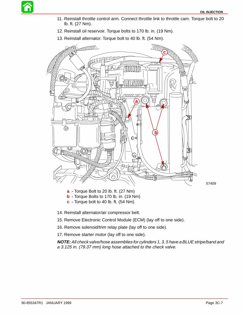
OIL INJECTION
90-855347R1 JANUARY 1999 Page 3C-7
11. Reinstall throttle control arm. Connect throttle link to throttle cam. Torque bolt to 20lb. ft. (27 Nm).
12. Reinstall oil reservoir. Torque bolts to 170 lb. in. (19 Nm).
13. Reinstall alternator. Torque bolt to 40 lb. ft. (54 Nm).
57409
b
a
c
a - Torque Bolt to 20 lb. ft. (27 Nm)b - Torque Bolts to 170 lb. in. (19 Nm)c - Torque bolt to 40 lb. ft. (54 Nm)
14. Reinstall alternator/air compressor belt.
15. Remove Electronic Control Module (ECM) (lay off to one side).
16. Remove solenoid/trim relay plate (lay off to one side).
17. Remove starter motor (lay off to one side).
NOTE: All check valve/hose assemblies for cylinders 1, 3, 5 have a BLUE stripe/band anda 3.125 in. (79.37 mm) long hose attached to the check valve.
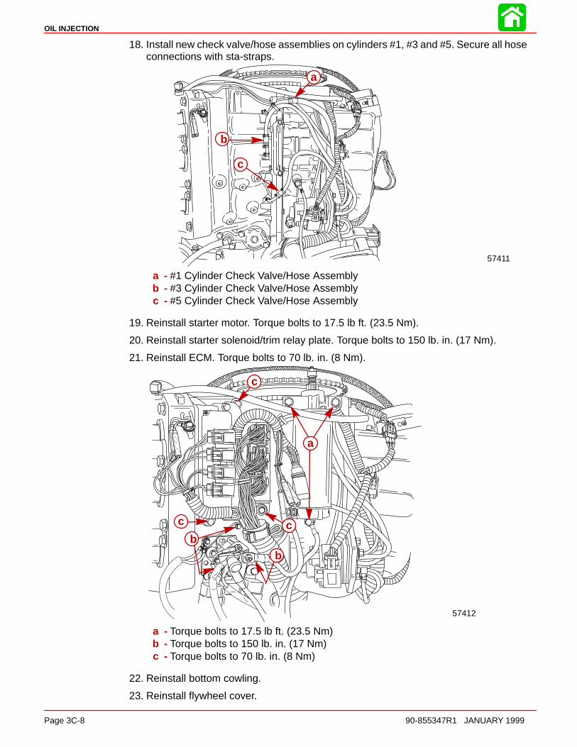
OIL INJECTION
Page 3C-8 90-855347R1 JANUARY 1999
18. Install new check valve/hose assemblies on cylinders #1, #3 and #5. Secure all hoseconnections with sta-straps.
57411
a
b
c
a - #1 Cylinder Check Valve/Hose Assemblyb - #3 Cylinder Check Valve/Hose Assemblyc - #5 Cylinder Check Valve/Hose Assembly
19. Reinstall starter motor. Torque bolts to 17.5 lb ft. (23.5 Nm).
20. Reinstall starter solenoid/trim relay plate. Torque bolts to 150 lb. in. (17 Nm).
21. Reinstall ECM. Torque bolts to 70 lb. in. (8 Nm).
57412
a
bb
c
cc
a - Torque bolts to 17.5 lb ft. (23.5 Nm)b - Torque bolts to 150 lb. in. (17 Nm)c - Torque bolts to 70 lb. in. (8 Nm)
22. Reinstall bottom cowling.
23. Reinstall flywheel cover.

OIL INJECTION
90-855347R1 JANUARY 1999 Page 3C-9
Oil Injection Hose InstallationInstall the correct inside diameter and length of hose between oil pump and fittings on theengine (see chart below). Cylinders #1, #3, #5 only have a BLUE stripe/band.
Fasten hoses on both ends with sta-straps.
Cyl #1
Cyl #2
Cyl #3
Cyl #4
Cyl #5Cyl #6
Cyl#1Cyl
#3
Cyl#5
Cyl#6
Cyl#4
Cyl#2
a
b
c
a
2
3
4
5
6
1
d
dd
d
d
d
e
7
a - Air Compressorb - Oil Pump
Cyl. #1 0.078 in. (1.98 mm) I.D. Check Valvewith 3.125 in. (79.4 mm) length Hose
Cyl. #3 0.078 in. (1.98 mm) I.D. Check Valvewith 3.125 in. (79.4 mm) length Hose
Cyl. #5 0.078 in. (1.98 mm) I.D. Check Valvewith 3.125 in. (79.4 mm) length Hose
Cyl. #2 0.063 in. (1.60 mm) I.D. Check Valvewith 1.250 in. (31.7 mm) length Hose
Cyl. #4 0.063 in. (1.60 mm) I.D. Check Valvewith 1.250 in. (31.7 mm) length Hose
Cyl. #6 0.063 in. (1.60 mm) I.D. Check Valvewith 1.250 in. (31.7 mm) length Hose
Note All check valve I.D. measurementsgiven are ± 0.002 in. (0.050 mm)
c - Fasten Hose Ends with Sta-Strapsd - Check Valvese - Check Valve (oil return)
Oil Hose Sizes
Hose Inside Diameter± .01 (0.25mm)
Length ± 0.20 (5.1 mm)
1 0.125 (3.2 mm) 16 in. (406 mm)
2 0.125 (3.2 mm) 20 in. (508 mm)
3 0.125 (3.2 mm) 16 in. (406 mm)
4 0.092 (2.3 mm) 28 in. (711 mm)
5 0.092 (2.3 mm) 24 in. (610 mm)
6 0.092 (2.3 mm) 24 in. (610 mm)
7 0.092 (2.3 mm) 24 in. (610 mm)
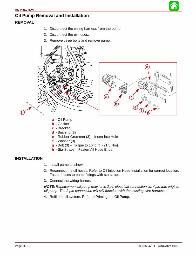
OIL INJECTION
Page 3C-10 90-855347R1 JANUARY 1999
Oil Pump Removal and InstallationREMOVAL
1. Disconnect the wiring harness from the pump.
2. Disconnect the oil hoses.
3. Remove three bolts and remove pump.
h
a c
d
ef g
b
a - Oil Pumpb - Gasketc - Bracketd - Bushing (3)e - Rubber Grommet (3) – Insert into Holef - Washer (3)g - Bolt (3) – Torque to 16 lb. ft. (21.5 Nm)h - Sta-Straps – Fasten All Hose Ends
INSTALLATION
1. Install pump as shown.
2. Reconnect the oil hoses. Refer to Oil Injection Hose Installation for correct location.Fasten hoses to pump fittings with sta-straps.
3. Connect the wiring harness.
NOTE: Replacement oil pump may have 2 pin electrical connection vs. 4 pin with originaloil pump. The 2 pin connection will still function with the existing wire harness.
4. Refill the oil system. Refer to Priming the Oil Pump.

OIL INJECTION
90-855347R1 JANUARY 1999 Page 3C-11
Engine Oil Reservoir Removal and InstallationREMOVAL
1. Disconnect the oil hoses. Plug the hoses to prevent spillage.
2. Disconnect the LIGHT BLUE wire leads.
3. Remove three bolts securing oil tank and fuel cooler to powerhead and remove tank.
a
b
cd
e fg
h
i
j
d e gg
k
a - Oil Reservoirb - Fuel Cooler (Design 1)c - Bolt (1) – Torque to 170 lb. in. (19 Nm)d - Washer (3)e - Rubber Grommet (3) – Insert into Holesf - Low Oil Switchg - Bushing (3)h - Grommet (2) – Insert into Holei - Bolt (2) – Torque to 170 lb. in. (19 Nm)j - Sta-Straps – Fasten All Hose Endsk - Fuel Cooler (Design 2)
INSTALLATION
1. Install oil reservoir as shown.
2. Fasten the oil hoses with sta-straps.
3. Connect the LIGHT BLUE wire leads.
4. Refill the oil system. Refer to Priming the Oil Pump.
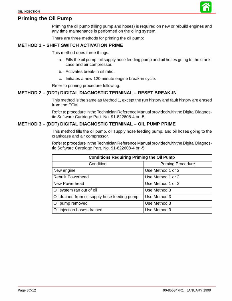
OIL INJECTION
Page 3C-12 90-855347R1 JANUARY 1999
Priming the Oil PumpPriming the oil pump (filling pump and hoses) is required on new or rebuild engines andany time maintenance is performed on the oiling system.
There are three methods for priming the oil pump:
METHOD 1 – SHIFT SWITCH ACTIVATION PRIME
This method does three things:
a. Fills the oil pump, oil supply hose feeding pump and oil hoses going to the crank-case and air compressor.
b. Activates break-in oil ratio.
c. Initiates a new 120 minute engine break-in cycle.
Refer to priming procedure following.
METHOD 2 – (DDT) DIGITAL DIAGNOSTIC TERMINAL – RESET BREAK-IN
This method is the same as Method 1, except the run history and fault history are erasedfrom the ECM.
Refer to procedure in the Technician Reference Manual provided with the Digital Diagnos-tic Software Cartridge Part. No. 91-822608-4 or -5.
METHOD 3 – (DDT) DIGITAL DIAGNOSTIC TERMINAL – OIL PUMP PRIME
This method fills the oil pump, oil supply hose feeding pump, and oil hoses going to thecrankcase and air compressor.
Refer to procedure in the Technician Reference Manual provided with the Digital Diagnos-tic Software Cartridge Part. No. 91-822608-4 or -5.
Conditions Requiring Priming the Oil Pump
Condition Priming Procedure
New engine Use Method 1 or 2
Rebuilt Powerhead Use Method 1 or 2
New Powerhead Use Method 1 or 2
Oil system ran out of oil Use Method 3
Oil drained from oil supply hose feeding pump Use Method 3
Oil pump removed Use Method 3
Oil injection hoses drained Use Method 3
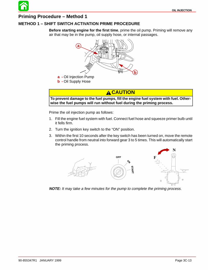
OIL INJECTION
90-855347R1 JANUARY 1999 Page 3C-13
Priming Procedure – Method 1METHOD 1 – SHIFT SWITCH ACTIVATION PRIME PROCEDURE
Before starting engine for the first time , prime the oil pump. Priming will remove anyair that may be in the pump, oil supply hose, or internal passages.
a
ba - Oil Injection Pumpb - Oil Supply Hose
CAUTIONTo prevent damage to the fuel pumps, fill the engine fuel system with fuel. Other-wise the fuel pumps will run without fuel during the priming process.
Prime the oil injection pump as follows:
1. Fill the engine fuel system with fuel. Connect fuel hose and squeeze primer bulb untilit fells firm.
2. Turn the ignition key switch to the “ON” position.
3. Within the first 10 seconds after the key switch has been turned on, move the remotecontrol handle from neutral into forward gear 3 to 5 times. This will automatically startthe priming process.
N
F
NOTE: It may take a few minutes for the pump to complete the priming process.
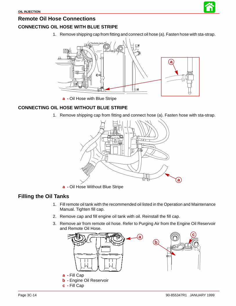
OIL INJECTION
Page 3C-14 90-855347R1 JANUARY 1999
Remote Oil Hose ConnectionsCONNECTING OIL HOSE WITH BLUE STRIPE
1. Remove shipping cap from fitting and connect oil hose (a). Fasten hose with sta-strap.
a
a - Oil Hose with Blue Stripe
CONNECTING OIL HOSE WITHOUT BLUE STRIPE
1. Remove shipping cap from fitting and connect hose (a). Fasten hose with sta-strap.
aa - Oil Hose Without Blue Stripe
Filling the Oil Tanks1. Fill remote oil tank with the recommended oil listed in the Operation and Maintenance
Manual. Tighten fill cap.
2. Remove cap and fill engine oil tank with oil. Reinstall the fill cap.
3. Remove air from remote oil hose. Refer to Purging Air from the Engine Oil Reservoirand Remote Oil Hose.
c
ba
a - Fill Capb - Engine Oil Reservoirc - Fill Cap

OIL INJECTION
90-855347R1 JANUARY 1999 Page 3C-15
Purging Air From the Engine Oil Reservoir and Remote Oil HoseNOTE: Before starting engine, make sure the oil pump has been primed.
1. Start the engine. Run the engine until all the air has been vented out of the reservoirand oil starts to flow out of the reservoir. Re-tighten fill cap.
a
a - Fill Cap
Oil Warning SystemsLOW OIL LEVEL
NOTE: The low oil condition must exist for a minimum of 15 seconds before horn or lightis activated.
The system is activated when the oil in the engine mounted oil reservoir tank drops below22 fl. oz. (175 ml). You still have an oil reserve remaining for 30 minutes of full speed oper-ation.
NOTE: The engine mounted oil reservoir (located beneath the top cowl) along with theremote oil tank will have to be refilled (refer to Filling the Oil tanks).
The warning system works as follows:
The OIL light (a) will come on and the warning horn sounds a series of four short tones.If you continue to operate the outboard, the light will stay on and the horn will sound fourshort tones every two minutes. The engine has to be shut off to reset the warning system.
a
OIL PUMP NOT FUNCTIONING ELECTRICALLY
The system is activated if the oil pump stops functioning electrically. No lubricating oil isbeing supplied to the engine. Stop the engine as soon as possible. Continuing to operatethe engine can result in severe engine damage.
The warning system works as follows:
The OIL light (a) and CHECK ENGINE light (b) will come on and the warning horn will be-gin sounding. The warning system will automatically reduce and limit the engine speedto 3000 RPM.
The engine has to be shut off to reset the warning system.
a
b

Low oil level in en-gine oil reservoir andalso remote oil tank
Low oil level in engineoil reservoir but not lowin remote oil tankNote: Oil level in engineoil reservoir should beup to the fill cap
Oil level is not lowin either tank
Refill both oil tanks.Purge air from en-gine oil tank. Referto procedure
Air was never purged fromengine oil tank
Fill cap is leaking air on re-mote tank
Remote oil hoses blocked orpunctured
Restricted oil outlet filter in re-mote oil tank
Air leak in upper portion onthe oil pickup tube
Faulty pressure check valve.Located in engine at end of(black without blue stripe) re-mote oil hose
Caps on remote tank must besealed and installed tight
Check hoses for a kink orleakage
Remove filter and clean
Replace tube
Replace check valve
Purge air from engine oil tank.Refer to procedure
Disconnect bluewires going to thelow oil float switch inthe engine oil reser-voir. Check switchfor continuity
Remove screw and pull outthe oil float switch from thetank. Check switch again forcontinuity
Continuity
Oil Float switch is faulty. Re-place switch
ContinuityFloat in oil tank is faulty. Re-place oil tank
No Continuity
Blue wire is shorted to groundNo Continuity
Problem Problem Problem ProblemOil leaks out ofexhaust or #6 cylinder
Pulse hose and oil supply hoseare reversed
Boat oil tank is mounted higher than pulse hose fitting on engineand oil tank is over-filled
ContinuityCheck continuity with engine run-ning and electrical system underload. Refer to Service Bulletin 98-3
OIL INJECTION
Page 3C-16 90-855347R1 JANUARY 1999
Oil System Troubleshooting
Low Oil Warning System is Activated

3D
EMISSIONS
90-855347R1 JANUARY 1999 Page 3D-1
FUEL SYSTEMSection 3D – Emissions
Table of Contents
Exhaust Emissions Standards 3D-1. . . . . . . . . . . . . . . . . What Are Emissions? 3D-1. . . . . . . . . . . . . . . . . . . . . . Hydrocarbons – HC 3D-1. . . . . . . . . . . . . . . . . . . . . . . . Carbon Monoxide – CO 3D-1. . . . . . . . . . . . . . . . . . . . Oxides of Nitrogen - NOx 3D-2. . . . . . . . . . . . . . . . . . . Controlling Emissions 3D-2. . . . . . . . . . . . . . . . . . . . . . Stoichiometric (14.7:1) Air/Fuel Ratio 3D-2. . . . . . . .
Outboard Hydrocarbon Emissions Reductions 3D-2. . . Stratified vs Homogenized Charge 3D-3. . . . . . . . . . . . .
Homogenized Charge 3D-3. . . . . . . . . . . . . . . . . . . . . . Stratified Charge 3D-4. . . . . . . . . . . . . . . . . . . . . . . . . .
Emissions Information 3D-4. . . . . . . . . . . . . . . . . . . . . . . . Manufacturer’s Responsibility: 3D-4. . . . . . . . . . . . . . Dealer Responsibility: 3D-5. . . . . . . . . . . . . . . . . . . . . . Owner Responsibility: 3D-5. . . . . . . . . . . . . . . . . . . . . . EPA Emission Regulations: 3D-5. . . . . . . . . . . . . . . . . Decal Location: 3D-6. . . . . . . . . . . . . . . . . . . . . . . . . . .
Replacement of Certification Label 3D-7. . . . . . . . . . . . . Removal 3D-7. . . . . . . . . . . . . . . . . . . . . . . . . . . . . . . . . Date Code Identification 3D-7. . . . . . . . . . . . . . . . . . . . Installation 3D-7. . . . . . . . . . . . . . . . . . . . . . . . . . . . . . . .
Exhaust Emissions Standards
Through the Environmental Protection Agency (EPA), the federal government has estab-lished exhaust emissions standards for all new marine engines sold in the United States.
What Are Emissions?Emissions are what comes out of the exhaust system in the exhaust gas when the engineis running. They are formed as a result of the process of combustion or incomplete com-bustion. To understand exhaust gas emissions, remember that both air and fuel are madeof several elements. Air contains oxygen and nitrogen among other elements; gasolinecontains mainly hydrogen and carbon. These four elements combine chemically duringcombustion. If combustion were complete, the mixture of air and gasoline would result inthese emissions: water, carbon dioxide and nitrogen, which are not harmful to the environ-ment. However, combustion is not usually complete. Also, potentially harmful gases canbe formed during and after combustion.
All marine engines must reduce the emission of certain pollutants, or potentially harmfulgases, in the exhaust to conform with levels legislated by the EPA. Emissions standardsbecome more stringent each year. Standards are set primarily with regard to three emis-sions: hydrocarbons (HC), carbon monoxide (CO) and oxides of nitrogen (NOx).
Hydrocarbons – HCGasoline is a hydrocarbon fuel. The two elements of hydrogen and carbon are burnedduring combustion in combination with oxygen. But they are not totally consumed. Somepass through the combustion chamber and exit the exhaust system as unburned gasesknown as hydrocarbons.
Carbon Monoxide – COCarbon is one of the elements that make up the fuel burned in the engine along with oxy-gen during the combustion process. If the carbon in the gasoline could combine withenough oxygen (one carbon atom with two oxygen atoms), it would come out of the en-gine in the form of carbon dioxide (CO2). CO2 is a harmless gas. However, carbon oftencombines with insufficient oxygen (one carbon atom with one oxygen atom). This formscarbon monoxide, CO. Carbon monoxide is the product of incomplete combustion andis a dangerous, potentially lethal gas.

EMISSIONS
Page 3D-2 90-855347R1 JANUARY 1999
Oxides of Nitrogen - NOxNOx is a slightly different byproduct of combustion. Nitrogen is one of the elements thatmakes up the air going into the engine. Under extremely high temperatures it combineswith oxygen to form oxides of nitrogen (NOx). This happens in the engine’s combustionchambers when temperatures are too high. NOx itself is not harmful, but when exposedto sunlight it combines with unburned hydrocarbons to create the visible air pollutantknown as smog. Smog is a serious problem in California as well as many other heavilypopulated areas of the United States.
Controlling EmissionsThere are two principle methods of reducing emissions from a two-stroke-cycle marineengine. The first method is to control the air/fuel ratio that goes into the combustion cham-ber. The second is to control the time when this air/fuel mixture enters the combustionchamber. Timing is important, to prevent any unburned mixture from escaping out of theexhaust port.
Stoichiometric (14.7:1) Air/Fuel RatioIn the search to control pollutants and reduce exhaust emissions, engineers have discov-ered that they can be reduced effectively if a gasoline engine operates at an air/fuel ratioof 14.7:1. the technical term for this ideal ratio is stoichiometric. An air/fuel ratio of 14.7:1provides the best control of all three elements in the exhaust under almost all conditions.The HC and CO content of the exhaust gas is influenced significantly by the air/fuel ratio.At an air/fuel ratio leaner than 14.7:1, HC and CO levels are low, but with a ratio richerthan 14.7:1 they rise rapidly. It would seem that controlling HC and CO by themselvesmight not be such a difficult task; the air/fuel ratio only needs to be kept leaner than 14.7:1.However, there is also NOx to consider.
As the air/fuel ratio becomes leaner, combustion temperatures increase. Higher combus-tion temperatures raise the NOx content of the exhaust. However, enrichening the air/fuelratio to decrease combustion temperatures or reduce NOx also increases HC and CO,as well as lowering fuel economy. So the solution to controlling NOx - as well as HC andCO - is to keep the air/fuel ratio as close to 14.7:1 as possible.
Outboard Hydrocarbon Emissions Reductions8 1/3% per Year Over 9 Model Years
0
20
40
60
80
100
120
96 97 98 99 2000 01 02 03 04 05 06 07 08

EMISSIONS
90-855347R1 JANUARY 1999 Page 3D-3
Stratified vs Homogenized Charge
DFI engines use a stratified charge inside the combustion chamber to aid in reducingemissions. All other models use a homogenized charge. The difference between the twois:
Homogenized ChargeA homogenized charge has the fuel/air particles mixed evenly throughout the cylinder.This mixing occurs inside the carburetor venturi, reed blocks and crankcase. Additionalmixing occurs as the fuel is forced through the transfer system into the cylinder.
The homogenized charge is easy to ignite when the air/fuel ratio is approximately 14.7:1.
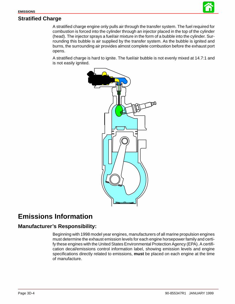
EMISSIONS
Page 3D-4 90-855347R1 JANUARY 1999
Stratified ChargeA stratified charge engine only pulls air through the transfer system. The fuel required forcombustion is forced into the cylinder through an injector placed in the top of the cylinder(head). The injector sprays a fuel/air mixture in the form of a bubble into the cylinder. Sur-rounding this bubble is air supplied by the transfer system. As the bubble is ignited andburns, the surrounding air provides almost complete combustion before the exhaust portopens.
A stratified charge is hard to ignite. The fuel/air bubble is not evenly mixed at 14.7:1 andis not easily ignited.
Emissions InformationManufacturer’s Responsibility:
Beginning with 1998 model year engines, manufacturers of all marine propulsion enginesmust determine the exhaust emission levels for each engine horsepower family and certi-fy these engines with the United States Environmental Protection Agency (EPA). A certifi-cation decal/emissions control information label, showing emission levels and enginespecifications directly related to emissions, must be placed on each engine at the timeof manufacture.

EMISSIONS
90-855347R1 JANUARY 1999 Page 3D-5
Dealer Responsibility:When performing service on all 1998 and later outboards that carry a certification, atten-tion must be given to any adjustments that are made that affect emission levels.
Adjustments must be kept within published factory specifications.
Replacement or repair of any emission related component must be executed in a mannerthat maintains emission levels within the prescribed certification standards.
Dealers are not to modify the engine in any manner that would alter the horsepower orallow emission levels to exceed their predetermined factory specifications.
Exceptions include manufacturers prescribed changes, such as that for altitude adjust-ments. Also included would be factory authorized:
• Installation of performance style gear housings by Mercury Marine.
• Service replacement parts modified, changed or superceded by Mercury Marine.
Owner Responsibility:The owner/operator is required to have engine maintenance performed to maintain emis-sion levels within prescribed certification standards.
The owner/operator is not to modify the engine in any manner that would alter the horse-power or allow emissions levels to exceed their predetermined factory specifications.
Single engine exceptions may be allowed with permission from the EPA for racing andtesting.
EPA Emission Regulations:All new 1998 and later outboards manufactured by Mercury Marine are certified to theUnited States Environmental Protection Agency as conforming to the requirements of theregulations for the control of air pollution from new outboard motors. This certification iscontingent on certain adjustments being set to factory standards. For this reason, the fac-tory procedure for servicing the product must be strictly followed and, whenever practica-ble, returned to the original intent of the design.
The responsibilities listed above are general and in no way a complete listing of the rulesand regulations pertaining to the EPA laws on exhaust emissions for marine products. Formore detailed information on this subject, you may contact the following locations:
VIA U.S. POSTAL SERVICE:Office of Mobile SourcesEngine Programs and Compliance DivisionEngine Compliance Programs Group (6403J)401 M St. NWWashington, DC 20460
VIA EXPRESS or COURIER MAIL:Office of Mobile SourcesEngine Programs and Compliance DivisionEngine Compliance Programs Group (6403J)501 3rd St. NWWashington, DC 20001
EPA INTERNET WEB SITE:http:/www.epa.gov/omswww
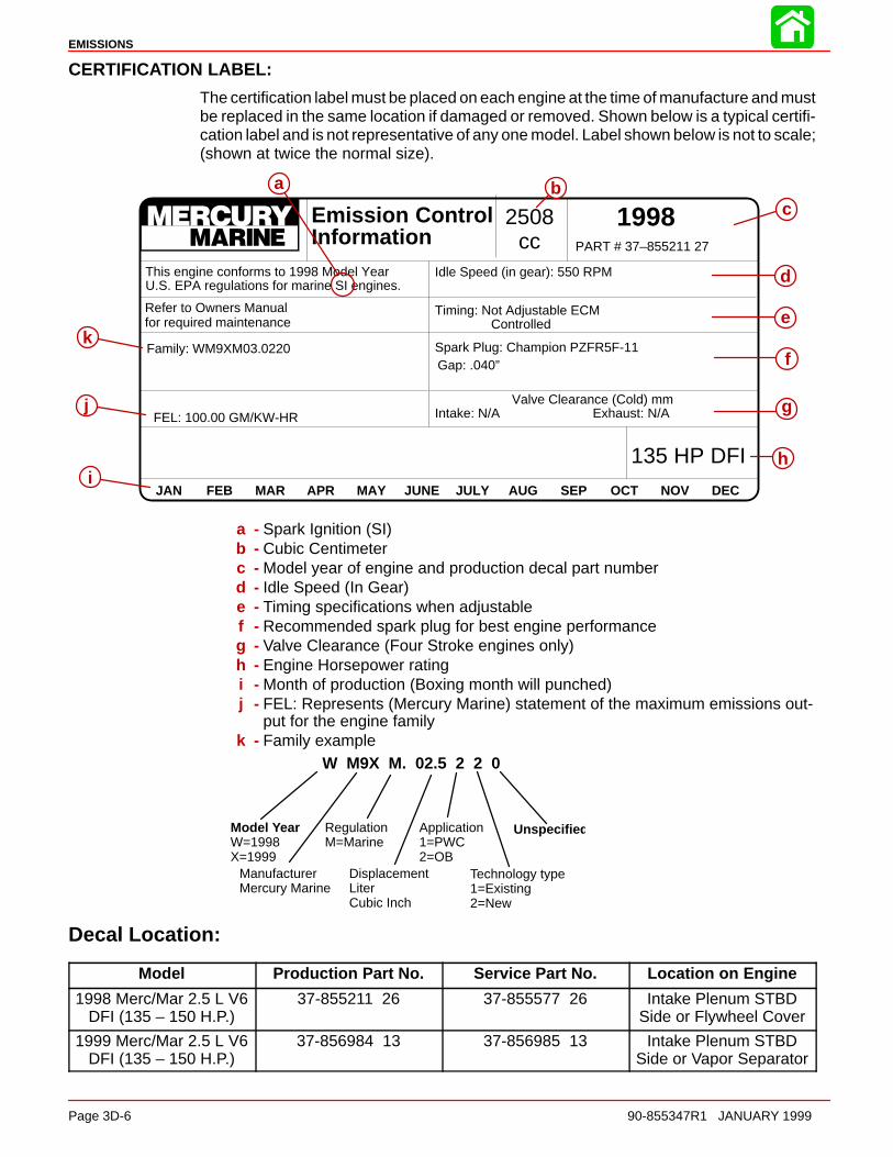
EMISSIONS
Page 3D-6 90-855347R1 JANUARY 1999
CERTIFICATION LABEL:
The certification label must be placed on each engine at the time of manufacture and mustbe replaced in the same location if damaged or removed. Shown below is a typical certifi-cation label and is not representative of any one model. Label shown below is not to scale;(shown at twice the normal size).
JAN FEB MAR APR MAY JUNE JULY AUG SEP OCT NOV DEC
Emission ControlInformation
1998PART # 37–855211 27
This engine conforms to 1998 Model Year U.S. EPA regulations for marine SI engines.
Idle Speed (in gear): 550 RPM
Timing: Not Adjustable ECMControlled
Spark Plug: Champion PZFR5F-11Gap: .040”
Valve Clearance (Cold) mmIntake: N/A Exhaust: N/A
Family: WM9XM03.0220
FEL: 100.00 GM/KW-HR
2508cc
135 HP DFI
a
k
Refer to Owners Manual for required maintenance
bc
hi
j
e
g
f
d
a - Spark Ignition (SI)b - Cubic Centimeterc - Model year of engine and production decal part numberd - Idle Speed (In Gear)e - Timing specifications when adjustablef - Recommended spark plug for best engine performanceg - Valve Clearance (Four Stroke engines only)h - Engine Horsepower ratingi - Month of production (Boxing month will punched)j - FEL: Represents (Mercury Marine) statement of the maximum emissions out-
put for the engine familyk - Family example
W M9X M. 02.5 2 2 0
Model YearW=1998X=1999
ManufacturerMercury Marine
RegulationM=Marine
DisplacementLiterCubic Inch
Application1=PWC2=OB
Technology type1=Existing2=New
Unspecifie d
Decal Location:
Model Production Part No. Service Part No. Location on Engine
1998 Merc/Mar 2.5 L V6DFI (135 – 150 H.P.)
37-855211 26 37-855577 26 Intake Plenum STBDSide or Flywheel Cover
1999 Merc/Mar 2.5 L V6DFI (135 – 150 H.P.)
37-856984 13 37-856985 13 Intake Plenum STBDSide or Vapor Separator

EMISSIONS
90-855347R1 JANUARY 1999 Page 3D-7
Replacement of Certification Label
IMPORTANT: By federal law, it is required that all 1998 and newer Mercury Marineoutboards have a visible and legible emission certification label. If this label is mis-sing or damaged, replacement labels can be obtained from Mercury Marine.
RemovalRemove all remaining pieces of the damaged or illegible label. Do not install new labelover the old label. Use a suitable solvent to remove any traces of the old label adhesivefrom the display location.
Date Code IdentificationCut and remove a “V” notch through the month of engine manufacture before installingthe new label. The month of manufacture can be found on the old label. If the label is mis-sing or the date code illegible, contact Mercury Marine Technical Service for assistance.
JAN FEB MAR APR MAY JUNE JULY AUG SEP OCT NOV DEC
Emission ControlInformation
1998PART # 37–855211 27
This engine conforms to 1998 Model Year U.S. EPA regulations for marine SI engines.
Idle Speed (in gear): 550 RPM
Timing: Not Adjustable ECMControlled
Spark Plug: Champion PZFR5F-11Gap: .040”
Valve Clearance (Cold) mmIntake: N/A Exhaust: N/A
Family: WM9XM03.0220
FEL: 100.00 GM/KW-HR
2508cc
135 HP DFI
Refer to Owners Manual for required maintenance
a
b
a - “V” Notchb - Month of Manufacture
InstallationInstall the label on a clean surface in the original factory location.
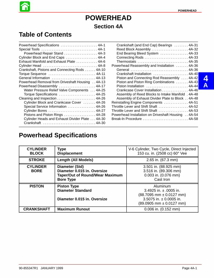
4A
POWERHEAD
90-855347R1 JANUARY 1999 Page 4A-1
POWERHEADSection 4A
Table of Contents
Powerhead Specifications 4A-1. . . . . . . . . . . . . . . . . . . . . Special Tools 4A-1. . . . . . . . . . . . . . . . . . . . . . . . . . . . . . . .
Powerhead Repair Stand 4A-3. . . . . . . . . . . . . . . . . . . Cylinder Block and End Caps 4A-4. . . . . . . . . . . . . . . . . . Exhaust Manifold and Exhaust Plate 4A-6. . . . . . . . . . . . Cylinder Head 4A-8. . . . . . . . . . . . . . . . . . . . . . . . . . . . . . . Crankshaft, Pistons and Connecting Rods 4A-10. . . . . . Torque Sequence 4A-11. . . . . . . . . . . . . . . . . . . . . . . . . . . General Information 4A-13. . . . . . . . . . . . . . . . . . . . . . . . . Powerhead Removal from Driveshaft Housing 4A-13. . Powerhead Disassembly 4A-17. . . . . . . . . . . . . . . . . . . . .
Water Pressure Relief Valve Components 4A-25. . . Torque Specifications 4A-25. . . . . . . . . . . . . . . . . . . . .
Cleaning and Inspection 4A-26. . . . . . . . . . . . . . . . . . . . . . Cylinder Block and Crankcase Cover 4A-26. . . . . . . Special Service Information 4A-26. . . . . . . . . . . . . . . . Cylinder Bores 4A-27. . . . . . . . . . . . . . . . . . . . . . . . . . . Pistons and Piston Rings 4A-28. . . . . . . . . . . . . . . . . . Cylinder Heads and Exhaust Divider Plate 4A-30. . . Crankshaft 4A-30. . . . . . . . . . . . . . . . . . . . . . . . . . . . . .
Crankshaft (and End Cap) Bearings 4A-31. . . . . . . . Reed Block Assembly 4A-32. . . . . . . . . . . . . . . . . . . . . End Bearing Bleed System 4A-33. . . . . . . . . . . . . . . . Connecting Rods 4A-33. . . . . . . . . . . . . . . . . . . . . . . . . Thermostats 4A-35. . . . . . . . . . . . . . . . . . . . . . . . . . . . .
Powerhead Reassembly and Installation 4A-36. . . . . . . General 4A-36. . . . . . . . . . . . . . . . . . . . . . . . . . . . . . . . . Crankshaft Installation 4A-40. . . . . . . . . . . . . . . . . . . . Piston and Connecting Rod Reassembly 4A-42. . . . Piston and Piston Ring Combinations 4A-43. . . . . . . Piston Installation 4A-44. . . . . . . . . . . . . . . . . . . . . . . . Crankcase Cover Installation 4A-46. . . . . . . . . . . . . . . Assembly of Reed Blocks to Intake Manifold 4A-48. Assembly of Exhaust Divider Plate to Block 4A-48. .
Reinstalling Engine Components 4A-51. . . . . . . . . . . . . . Throttle Lever and Shift Shaft 4A-52. . . . . . . . . . . . . . . . . Throttle Lever and Shift Shaft 4A-53. . . . . . . . . . . . . . . . . Powerhead Installation on Driveshaft Housing 4A-54. . Break-ln Procedure 4A-58. . . . . . . . . . . . . . . . . . . . . . . . . .
Powerhead Specifications
CYLINDERBLOCK
TypeDisplacement
V-6 Cylinder, Two Cycle, Direct Injected153 cu. in. (2508 cc) 60° Vee
STROKE Length (All Models) 2.65 in. (67.3 mm)
CYLINDERBORE
Diameter (Std)Diameter 0.015 in. OversizeTaper/Out of Round/Wear MaximumBore Type
3.501 in. (88.925 mm)3.516 in. (89.306 mm)0.003 in. (0.076 mm)
Cast Iron
PISTON Piston TypeDiameter Standard
Diameter 0.015 in. Oversize
Aluminum3.4925 in. ± .0005 in.
(88.7095 mm ± 0.0127 mm)3.5075 in. ± 0.0005 in.
(89.0905 mm ± 0.0127 mm)
CRANKSHAFT Maximum Runout 0.006 in. (0.152 mm)
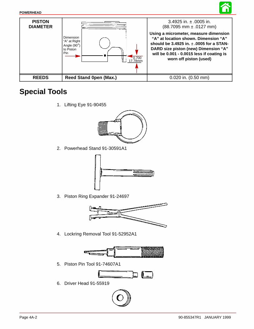
POWERHEAD
Page 4A-2 90-855347R1 JANUARY 1999
PISTONDIAMETER
Dimension“A” at RightAngle (90°)to PistonPin
0.70017.78mm
3.4925 in. ± .0005 in.(88.7095 mm ± .0127 mm)
Using a micrometer, measure dimension“A” at location shown. Dimension “A”
should be 3.4925 in. ± .0005 for a STAN-DARD size piston (new) Dimension “A”will be 0.001 - 0.0015 less if coating is
worn off piston (used)
REEDS Reed Stand 0pen (Max.) 0.020 in. (0.50 mm)
Special Tools
1. Lifting Eye 91-90455
2. Powerhead Stand 91-30591A1
3. Piston Ring Expander 91-24697
4. Lockring Removal Tool 91-52952A1
5. Piston Pin Tool 91-74607A1
6. Driver Head 91-55919

POWERHEAD
90-855347R1 JANUARY 1999 Page 4A-3
7. Universal Puller Plate 91-37241
8. Snap Ring Pliers 91-24283
9. Lockring Installation Tool 91-77109A1
10. Piston Ring Compressor for 2.5 Litre (153 cu. in.) 91-818773
11. Compression Tester 91-29287
Powerhead Repair StandA powerhead repair stand may be purchased from:
Bob Kerr’s Marine Tool Co. P.O. Box 1135 Winter Garden, FL 32787 Telephone: (305) 656-2089
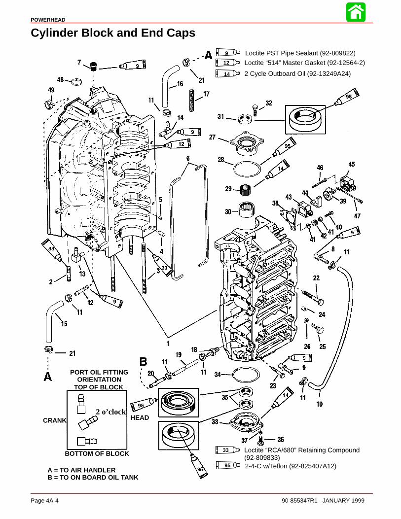
POWERHEAD
Page 4A-4 90-855347R1 JANUARY 1999
Cylinder Block and End Caps
TOP OF BLOCK
CRANK
BOTTOM OF BLOCK
HEAD
PORT OIL FITTINGORIENTATION
2 o’clock
Loctite PST Pipe Sealant (92-809822)9
12 Loctite “514” Master Gasket (92-12564-2)
14 2 Cycle Outboard Oil (92-13249A24)
Loctite “RCA/680” Retaining Compound (92-809833)
33
95 2-4-C w/Teflon (92-825407A12)A = TO AIR HANDLERB = TO ON BOARD OIL TANK

POWERHEAD
90-855347R1 JANUARY 1999 Page 4A-5
Cylinder Block and End Caps
REF. TORQUEREF.NO. QTY. DESCRIPTION lb-in lb-ft Nm.
1 1 CYLINDER BLOCK2 6 STUD–powerhead (1-3/4 IN.)
32 STUD–powerhead (5-1/2 IN.)
3 2 STUD–powerhead (6-3/4 IN.)4 2 DOWEL PIN–locating5 2 DOWEL PIN (BEARING RACE)6 2 GASKET–sealing7 1 PIPE PLUG (1/2-14) Drive Tight8 1 CHECK VALVE9 1 CHECK VALVE10 1 TUBING (19 IN.)11 10 STA STRAP12 2 FITTING (STRAIGHT)(STARBOARD - TOP/BOTTOM)13 1 FITTING (ELBOW) (STARBOARD - CENTER)14 3 FITTING (ELBOW) (PORT)
152 TUBING (16 IN.) (TOP/BOTTOM)
15 1 TUBING (20 IN.) (CENTER)16 3 TUBING (24-1/2 IN.)17 1 CONDUIT (7 IN.)18 1 FITTING19 1 TUBING (11-1/2 IN.)20 1 CONNECTOR21 6 STA-STRAP22 8 SCREW (3/8-16 x 3-1/4) 37 5023 6 SCREW (.312-18 x 1-1/4) 15 2024 1 CAP25 1 ADJUSTING SCREW (1/4-20 x 1-3/4)26 1 JAM NUT27 1 UPPER END CAP28 1 O-RING29 1 ROLLER BEARING30 1 BEARING RACE31 1 OIL SEAL32 4 SCREW (5/16-18 x 1) 205 17 2333 1 LOWER END CAP34 1 O-RING (3-1/4 IN. I.D.)35 2 OIL SEAL36 4 SCREW (1/4-20 x 3/4) 80 937 4 LOCKWASHER38 1 BRACKET39 1 TPI LEVER40 3 SCREW -Bracket to crankcase 70 841 6 BUSHING42 3 GROMMET43 1 THROTTLE POSITION SENSOR (INSIDE)44 1 SPACER45 1 THROTTLE POSITION SENSOR (OUTSIDE)46 3 SCREW -TPS to bracket (#10-32 x 2-3/4 IN.) 15 1.747 1 THROTTLE LINK48 1 PLUG-Serial Number49 1 STA-STRAP-Oil Lines
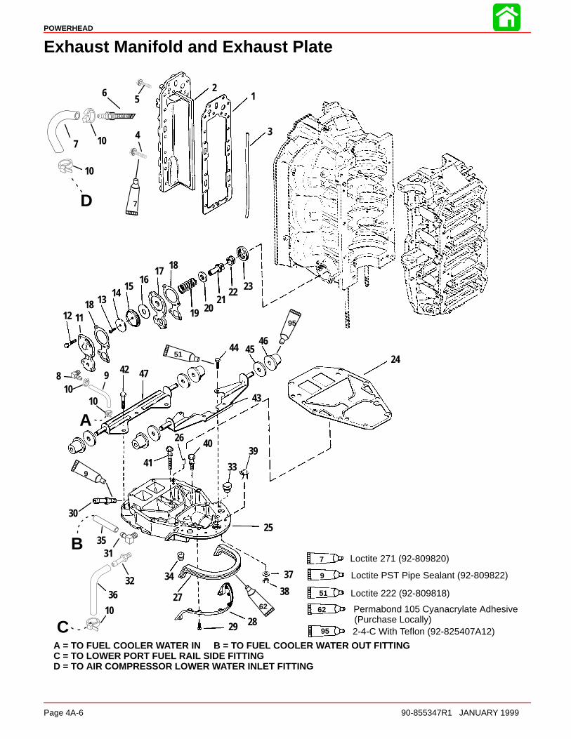
POWERHEAD
Page 4A-6 90-855347R1 JANUARY 1999
Exhaust Manifold and Exhaust Plate
12
3
31
4
5
8 910
111218 13
1415
1617
19 2021
22 23
24
2530
26
27
2829
37
38
39
33
34
40
41
42
43
44 4546
47
18
10
32
35
36
10
10
6
7
D
A
B
C10 Permabond 105 Cyanacrylate Adhesive
(Purchase Locally)62
95
51
9
62
7
A = TO FUEL COOLER WATER IN B = TO FUEL COOLER WATER OUT FITTINGC = TO LOWER PORT FUEL RAIL SIDE FITTINGD = TO AIR COMPRESSOR LOWER WATER INLET FITTING
51 Loctite 222 (92-809818)
7 Loctite 271 (92-809820)
95 2-4-C With Teflon (92-825407A12)
Loctite PST Pipe Sealant (92-809822)9
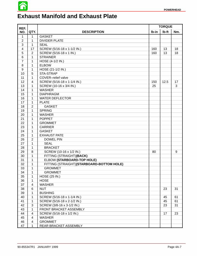
POWERHEAD
90-855347R1 JANUARY 1999 Page 4A-7
Exhaust Manifold and Exhaust Plate
REF. TORQUEREF.NO. QTY. DESCRIPTION lb-in lb-ft Nm.
1 1 GASKET2 1 DIVIDER PLATE3 1 SEAL4 17 SCREW (5/16-18 x 1-1/2 IN.) 160 13 185 2 SCREW (5/16-18 x 1 IN.) 160 13 186 1 STRAINER7 1 HOSE (4-1/2 IN.)8 1 ELBOW9 1 HOSE (21-1/2 IN.)10 5 STA-STRAP11 1 COVER–relief valve12 4 SCREW (5/16-18 x 1-1/4 IN.) 150 12.5 1713 1 SCREW (10-16 x 3/4 IN.) 25 314 1 WASHER15 1 DIAPHRAGM16 1 WATER DEFLECTOR17 1 PLATE18 2 GASKET19 1 SPRING20 1 WASHER21 1 POPPET22 1 GROMMET23 1 CARRIER24 1 GASKET25 1 EXHAUST PATE26 2 DOWEL PIN27 1 SEAL28 1 BRACKET29 8 SCREW (10-16 x 1/2 IN.) 80 930 1 FITTING (STRAIGHT)(BACK)31 1 ELBOW (STARBOARD-TOP HOLE)32 1 FITTING (STRAIGHT)(STARBOARD-BOTTOM HOLE)33 1 GROMMET34 1 GROMMET35 1 HOSE (25 IN.)36 1 HOSE37 4 WASHER38 6 NUT 23 3139 1 BUSHING40 1 SCREW (5/16-18 x 1-1/4 IN.) 45 6141 1 SCREW (5/16-18 x 2-1/2 IN.) 45 6142 3 SCREW (3/8-16 x 3-1/2 IN.) 23 3143 1 FRONT BRACKET ASSEMBLY44 4 SCREW (5/16-18 x 1/2 IN.) 17 2345 4 WASHER46 4 GROMMET47 1 REAR BRACKET ASSEMBLY

POWERHEAD
Page 4A-8 90-855347R1 JANUARY 1999
Cylinder Head
3
4
56
7
8
9
11
10
14
1516
1
2
13
4
12
13
A
13
13
9
9
6
14
15°
Back of Engine
Water Fitting OrientationLooking Down at Top of Block
Dielectric Grease (92-823506--1)6
Loctite PST Pipe Sealant (92-809822)9
14 2 Cycle Outboard Oil (92-13249A24)A = TO STRAIGHT FITTING ON BACK OF EXHAUST PLATE

POWERHEAD
90-855347R1 JANUARY 1999 Page 4A-9
Cylinder Head
REF. TORQUEREF.NO. QTY. DESCRIPTION lb-in lb-ft Nm.
11 CYLINDER HEAD (PORT)
11 CYLINDER HEAD (STARBOARD)
2 2 GASKET
3 24 BOLT (2 IN.)30 lb-ft
(40.7 N·m) thentighten additional 90°
4 4 DOWEL PIN5 2 GASKET6 2 COVER7 2 THERMOSTAT (143 degrees)8 4 SCREW (M6 x 25) 200 16.5 22.5
9 1 ELBOW (STARBOARD)10 1 ELBOW (PORT)11 1 HOSE (21-1/2 IN.)12 1 HOSE (11-1/2 IN.)13 5 STA-STRAP14 1 TEMPERATURE SENSOR (STARBOARD)15 1 RETAINER
16 1 SCREW (M8 x 12) 200 16.5 22.5
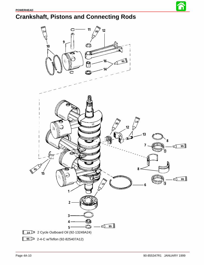
POWERHEAD
Page 4A-10 90-855347R1 JANUARY 1999
Crankshaft, Pistons and Connecting Rods
1
2
3
8
4
5
6
7
12
13
14
15
16
12
910
11
8
14
95
95
95
95
1495
95
9514
14 2 Cycle Outboard Oil (92-13249A24)
95 2-4-C w/Teflon (92-825407A12)

POWERHEAD
90-855347R1 JANUARY 1999 Page 4A-11
Crankshaft, Pistons and Connecting Rods
REF. TORQUEREF.NO. QTY. DESCRIPTION lb-in lb-ft Nm.
1 1 CRANKSHAFT ASSEMBLY
2 1 BALL BEARING (LOWER)3 1 RETAINING RING4 1 CARRIER ASSEMBLY5 1 SEAL6 7 RING–sealing7 2 ROLLER BEARING
8 2 RACE
93 PISTON (STARBOARD)
93 PISTON (PORT)
10 1 PISTON RING11 12 LOCK RING12 6 CONNECTING ROD ASSEMBLY
13 12 SCREW
1st Torque: 15 lb-in2nd Torque: 30 lb-ft
Turn Screw addition-al 90° after 2nd
torque14 12 WASHER15 6 ROLLER BEARING ASSEMBLY16 174 NEEDLE BEARING–piston end
Torque Sequence
CRANKCASE COVER BOLTS (AND TORQUE SEQUENCE)
1
23
4
5 6
78
a
b
a - Add light oil to threads and bolt face: 8 Bolts (3/8 in. - 16 in.) 38 lb. ft. (51.5 N·m)
b - Bolts (5/16 in. - 18) 180 lb. in. (20 N·m)
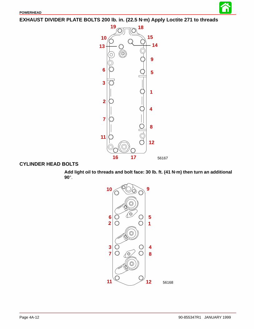
POWERHEAD
Page 4A-12 90-855347R1 JANUARY 1999
EXHAUST DIVIDER PLATE BOLTS 200 lb. in. (22.5 N·m) Apply Loctite 271 to threads
56167
1
2
3
4
56
7
8
9
1112
13 14
15
16 17
1819
10
CYLINDER HEAD BOLTS
Add light oil to threads and bolt face: 30 lb. ft. (41 N·m) then turn an additional90°.
56168
12
3 4
56
7 8
910
11 12
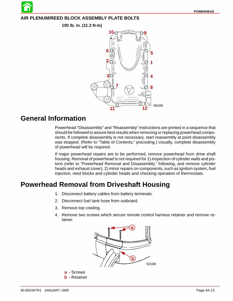
POWERHEAD
90-855347R1 JANUARY 1999 Page 4A-13
AIR PLENUM/REED BLOCK ASSEMBLY PLATE BOLTS
100 lb. in. (11.3 N·m)
56160
12
3 4
56
7 8
910
11 12
General InformationPowerhead “Disassembly” and “Reassembly” instructions are printed in a sequence thatshould be followed to assure best results when removing or replacing powerhead compo-nents. If complete disassembly is not necessary, start reassembly at point disassemblywas stopped. (Refer to “Table of Contents,” preceding.) Usually, complete disassemblyof powerhead will be required.
If major powerhead repairs are to be performed, remove powerhead from drive shafthousing. Removal of powerhead is not required for 1) inspection of cylinder walls and pis-tons (refer to “Powerhead Removal and Disassembly,” following, and remove cylinderheads and exhaust cover), 2) minor repairs on components, such as ignition system, fuelinjection, reed blocks and cylinder heads and checking operation of thermostats.
Powerhead Removal from Driveshaft Housing1. Disconnect battery cables from battery terminals.
2. Disconnect fuel tank hose from outboard.
3. Remove top cowling.
4. Remove two screws which secure remote control harness retainer and remove re-tainer.
52188
a
b
a - Screwsb - Retainer

POWERHEAD
Page 4A-14 90-855347R1 JANUARY 1999
5. Disconnect remote oil tank hose connector.
6. Disconnect remote control harness from powerhead harness connector and wires asshown.
GRN/WHTBLU/WHT
BRN/WHTTAN
BLU/WHTGRN/WHT a
a - Power Trim Connections
7. Remove sta-strap which secures tell-tale hose to fitting on lower cowl and removehose from fitting.
56141
a
a - Tell-tale Hose
8. Disconnect warning gauge harness.
1
2 3 45
6
acbd
acbd
e
a - TAN/BLACKb - TAN/WHITEc - PINK/LT. BLUE to PINK/LT. BLUEd - ORANGEe - Sta-Straps
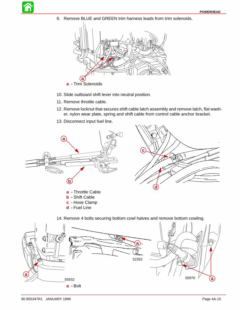
POWERHEAD
90-855347R1 JANUARY 1999 Page 4A-15
9. Remove BLUE and GREEN trim harness leads from trim solenoids.
aa - Trim Solenoids
10. Slide outboard shift lever into neutral position.
11. Remove throttle cable.
12. Remove locknut that secures shift cable latch assembly and remove latch, flat wash-er, nylon wear plate, spring and shift cable from control cable anchor bracket.
13. Disconnect input fuel line.
c
a
bd
a - Throttle Cableb - Shift Cablec - Hose Clampd - Fuel Line
14. Remove 4 bolts securing bottom cowl halves and remove bottom cowling.
55970
52352
55932a
a
a
a - Bolt

POWERHEAD
Page 4A-16 90-855347R1 JANUARY 1999
15. Remove fuel cooler inlet and outlet water hoses from fittings on exhaust adaptor plateand poppet valve cover. Remove excess air hose (from port fuel rail) from fitting onexhaust adaptor plate.
16. Remove thermostat cover hose from exhaust adaptor plate.
56158
56159
d
a
b
ca - Fuel Cooler Outlet Water Hoseb - Fuel Cooler Inlet Water Hosec - Air Hosed - Thermostat Cover Hose
17. Remove 10 nuts and washers (five each side) from powerhead base.
18. Remove plastic cap from center of flywheel and install LIFTING EYE (91-90455) intoflywheel at least five full turns. Using a hoist, lift powerhead assembly from driveshafthousing.
56162
51846
aa
aa
b
a
a - Nuts and Washers (5 Each Side)b - Lifting Eye
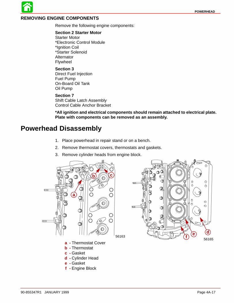
POWERHEAD
90-855347R1 JANUARY 1999 Page 4A-17
REMOVING ENGINE COMPONENTS
Remove the following engine components:
Section 2 Starter MotorStarter Motor*Electronic Control Module*Ignition Coil*Starter SolenoidAlternatorFlywheel
Section 3Direct Fuel InjectionFuel PumpOn-Board Oil TankOil Pump
Section 7Shift Cable Latch AssemblyControl Cable Anchor Bracket
*All ignition and electrical components should remain attached to electrical plate.Plate with components can be removed as an assembly.
Powerhead Disassembly
1. Place powerhead in repair stand or on a bench.
2. Remove thermostat covers, thermostats and gaskets.
3. Remove cylinder heads from engine block.
56165
def56163
a
b c
a - Thermostat Coverb - Thermostatc - Gasketd - Cylinder Heade - Gasketf - Engine Block

POWERHEAD
Page 4A-18 90-855347R1 JANUARY 1999
4. Remove exhaust manifold cover and seal.
5. Referring to Section 3B, remove air plenum/reed block/adaptor plate assembly fromcylinder block.
d
56166
a
c
b
a - Exhaust Manifold Coverb - Sealc - Gasketd - Reed Block/Adaptor Plate Assembly
6. Inspect reeds as outlined in “Cleaning and Inspection”.
561697. Remove bolts from end caps.

POWERHEAD
90-855347R1 JANUARY 1999 Page 4A-19
UPPER END CAP
51854
a
a - Crankcase Attaching End Cap Bolts
LOWER END CAP
51849
a
a - Crankcase Attaching End Cap Bolts
1. Remove bolts which secure crankcase cover to cylinder block.
2. Pry crankcase cover off cylinder block using pry bars in locations shown.
51845
ab
a
a - Pry Pointsb - Crankcase Cover
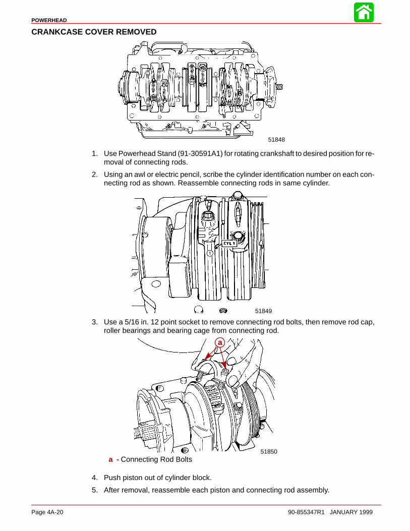
POWERHEAD
Page 4A-20 90-855347R1 JANUARY 1999
CRANKCASE COVER REMOVED
51848
1. Use Powerhead Stand (91-30591A1) for rotating crankshaft to desired position for re-moval of connecting rods.
2. Using an awl or electric pencil, scribe the cylinder identification number on each con-necting rod as shown. Reassemble connecting rods in same cylinder.
51849
ÄÄ
3. Use a 5/16 in. 12 point socket to remove connecting rod bolts, then remove rod cap,roller bearings and bearing cage from connecting rod.
51850
a
a - Connecting Rod Bolts
4. Push piston out of cylinder block.
5. After removal, reassemble each piston and connecting rod assembly.
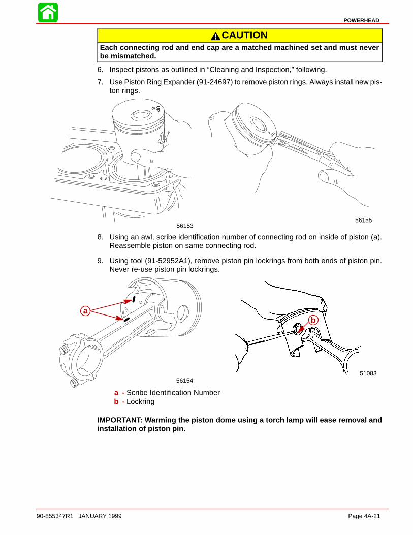
POWERHEAD
90-855347R1 JANUARY 1999 Page 4A-21
CAUTIONEach connecting rod and end cap are a matched machined set and must neverbe mismatched.
6. Inspect pistons as outlined in “Cleaning and Inspection,” following.
7. Use Piston Ring Expander (91-24697) to remove piston rings. Always install new pis-ton rings.
5615556153
8. Using an awl, scribe identification number of connecting rod on inside of piston (a).Reassemble piston on same connecting rod.
9. Using tool (91-52952A1), remove piston pin lockrings from both ends of piston pin.Never re-use piston pin lockrings.
5108356154
ba
a - Scribe Identification Numberb - Lockring
IMPORTANT: Warming the piston dome using a torch lamp will ease removal andinstallation of piston pin.
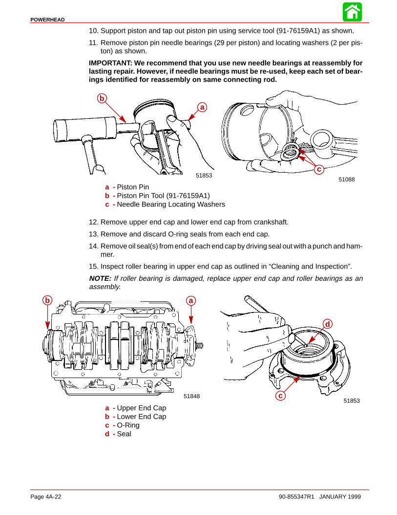
POWERHEAD
Page 4A-22 90-855347R1 JANUARY 1999
10. Support piston and tap out piston pin using service tool (91-76159A1) as shown.
11. Remove piston pin needle bearings (29 per piston) and locating washers (2 per pis-ton) as shown.
IMPORTANT: We recommend that you use new needle bearings at reassembly forlasting repair. However, if needle bearings must be re-used, keep each set of bear-ings identified for reassembly on same connecting rod.
5108851853
ba
c
a - Piston Pinb - Piston Pin Tool (91-76159A1)c - Needle Bearing Locating Washers
12. Remove upper end cap and lower end cap from crankshaft.
13. Remove and discard O-ring seals from each end cap.
14. Remove oil seal(s) from end of each end cap by driving seal out with a punch and ham-mer.
15. Inspect roller bearing in upper end cap as outlined in “Cleaning and Inspection”.
NOTE: If roller bearing is damaged, replace upper end cap and roller bearings as anassembly.
51853c
d
51848
ab
a - Upper End Capb - Lower End Capc - O-Ringd - Seal
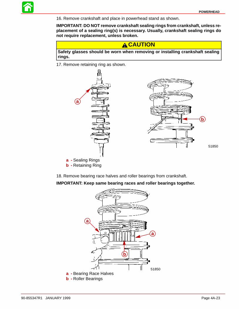
POWERHEAD
90-855347R1 JANUARY 1999 Page 4A-23
16. Remove crankshaft and place in powerhead stand as shown.
IMPORTANT: DO NOT remove crankshaft sealing rings from crankshaft, unless re-placement of a sealing ring(s) is necessary. Usually, crankshaft sealing rings donot require replacement, unless broken.
CAUTIONSafety glasses should be worn when removing or installing crankshaft sealingrings.
17. Remove retaining ring as shown.
51850
a
b
a - Sealing Ringsb - Retaining Ring
18. Remove bearing race halves and roller bearings from crankshaft.
IMPORTANT: Keep same bearing races and roller bearings together.
51850
a
a
b
a - Bearing Race Halvesb - Roller Bearings
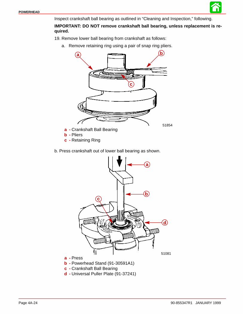
POWERHEAD
Page 4A-24 90-855347R1 JANUARY 1999
Inspect crankshaft ball bearing as outlined in “Cleaning and Inspection,” following.
IMPORTANT: DO NOT remove crankshaft ball bearing, unless replacement is re-quired.
19. Remove lower ball bearing from crankshaft as follows:
a. Remove retaining ring using a pair of snap ring pliers.
a b
c
51854a - Crankshaft Ball Bearingb - Pliersc - Retaining Ring
b. Press crankshaft out of lower ball bearing as shown.
51081
a
bc
d
a - Pressb - Powerhead Stand (91-30591A1)c - Crankshaft Ball Bearingd - Universal Puller Plate (91-37241)
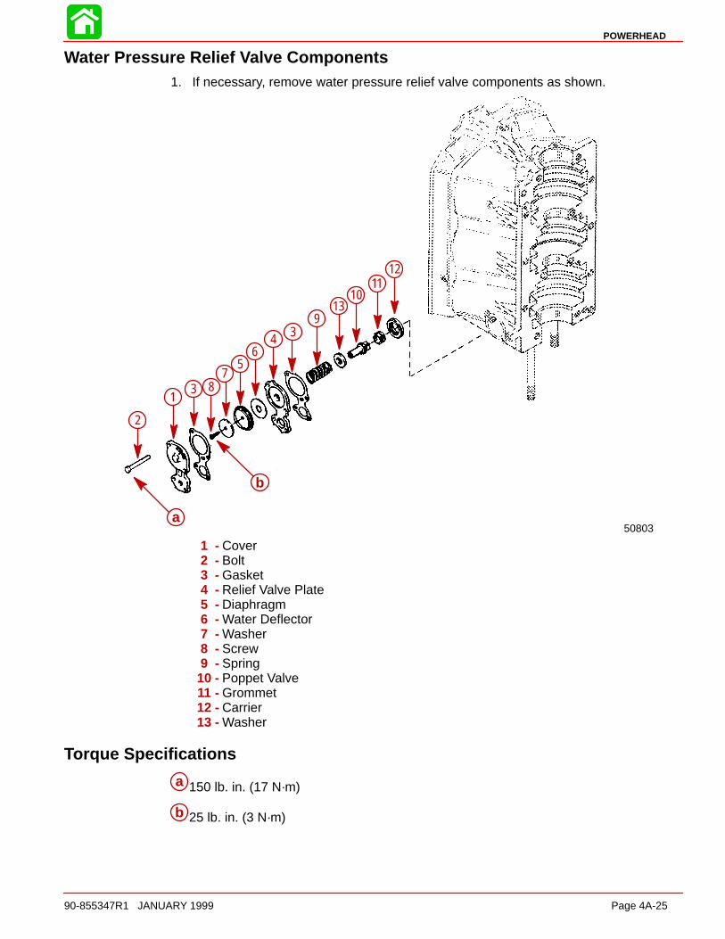
POWERHEAD
90-855347R1 JANUARY 1999 Page 4A-25
Water Pressure Relief Valve Components1. If necessary, remove water pressure relief valve components as shown.
a
b
1
2
3
4
56
78
9
1011
12
13
3
50803
1 - Cover2 - Bolt3 - Gasket4 - Relief Valve Plate5 - Diaphragm6 - Water Deflector7 - Washer8 - Screw9 - Spring
10 - Poppet Valve11 - Grommet12 - Carrier13 - Washer
Torque Specifications
a 150 lb. in. (17 N·m)
b 25 lb. in. (3 N·m)
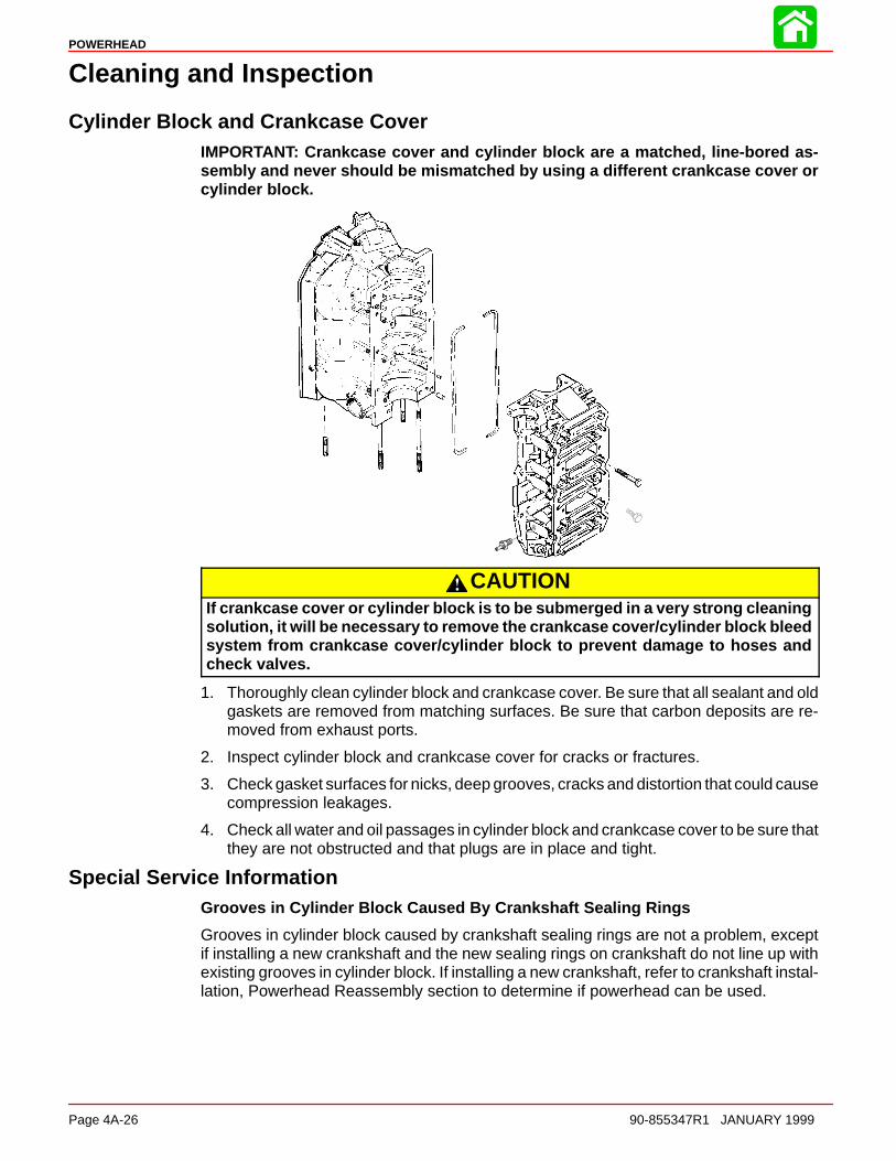
POWERHEAD
Page 4A-26 90-855347R1 JANUARY 1999
Cleaning and Inspection
Cylinder Block and Crankcase CoverIMPORTANT: Crankcase cover and cylinder block are a matched, line-bored as-sembly and never should be mismatched by using a different crankcase cover orcylinder block.
CAUTIONIf crankcase cover or cylinder block is to be submerged in a very strong cleaningsolution, it will be necessary to remove the crankcase cover/cylinder block bleedsystem from crankcase cover/cylinder block to prevent damage to hoses andcheck valves.
1. Thoroughly clean cylinder block and crankcase cover. Be sure that all sealant and oldgaskets are removed from matching surfaces. Be sure that carbon deposits are re-moved from exhaust ports.
2. Inspect cylinder block and crankcase cover for cracks or fractures.
3. Check gasket surfaces for nicks, deep grooves, cracks and distortion that could causecompression leakages.
4. Check all water and oil passages in cylinder block and crankcase cover to be sure thatthey are not obstructed and that plugs are in place and tight.
Special Service InformationGrooves in Cylinder Block Caused By Crankshaft Sealing Rings
Grooves in cylinder block caused by crankshaft sealing rings are not a problem, exceptif installing a new crankshaft and the new sealing rings on crankshaft do not line up withexisting grooves in cylinder block. If installing a new crankshaft, refer to crankshaft instal-lation, Powerhead Reassembly section to determine if powerhead can be used.
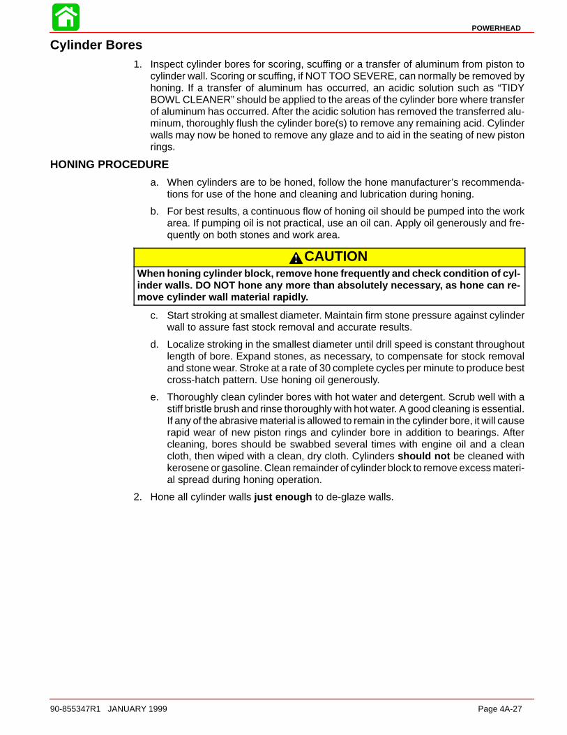
POWERHEAD
90-855347R1 JANUARY 1999 Page 4A-27
Cylinder Bores1. Inspect cylinder bores for scoring, scuffing or a transfer of aluminum from piston to
cylinder wall. Scoring or scuffing, if NOT TOO SEVERE, can normally be removed byhoning. If a transfer of aluminum has occurred, an acidic solution such as “TIDYBOWL CLEANER” should be applied to the areas of the cylinder bore where transferof aluminum has occurred. After the acidic solution has removed the transferred alu-minum, thoroughly flush the cylinder bore(s) to remove any remaining acid. Cylinderwalls may now be honed to remove any glaze and to aid in the seating of new pistonrings.
HONING PROCEDURE
a. When cylinders are to be honed, follow the hone manufacturer’s recommenda-tions for use of the hone and cleaning and lubrication during honing.
b. For best results, a continuous flow of honing oil should be pumped into the workarea. If pumping oil is not practical, use an oil can. Apply oil generously and fre-quently on both stones and work area.
CAUTIONWhen honing cylinder block, remove hone frequently and check condition of cyl-inder walls. DO NOT hone any more than absolutely necessary, as hone can re-move cylinder wall material rapidly.
c. Start stroking at smallest diameter. Maintain firm stone pressure against cylinderwall to assure fast stock removal and accurate results.
d. Localize stroking in the smallest diameter until drill speed is constant throughoutlength of bore. Expand stones, as necessary, to compensate for stock removaland stone wear. Stroke at a rate of 30 complete cycles per minute to produce bestcross-hatch pattern. Use honing oil generously.
e. Thoroughly clean cylinder bores with hot water and detergent. Scrub well with astiff bristle brush and rinse thoroughly with hot water. A good cleaning is essential.If any of the abrasive material is allowed to remain in the cylinder bore, it will causerapid wear of new piston rings and cylinder bore in addition to bearings. Aftercleaning, bores should be swabbed several times with engine oil and a cleancloth, then wiped with a clean, dry cloth. Cylinders should not be cleaned withkerosene or gasoline. Clean remainder of cylinder block to remove excess materi-al spread during honing operation.
2. Hone all cylinder walls just enough to de-glaze walls.
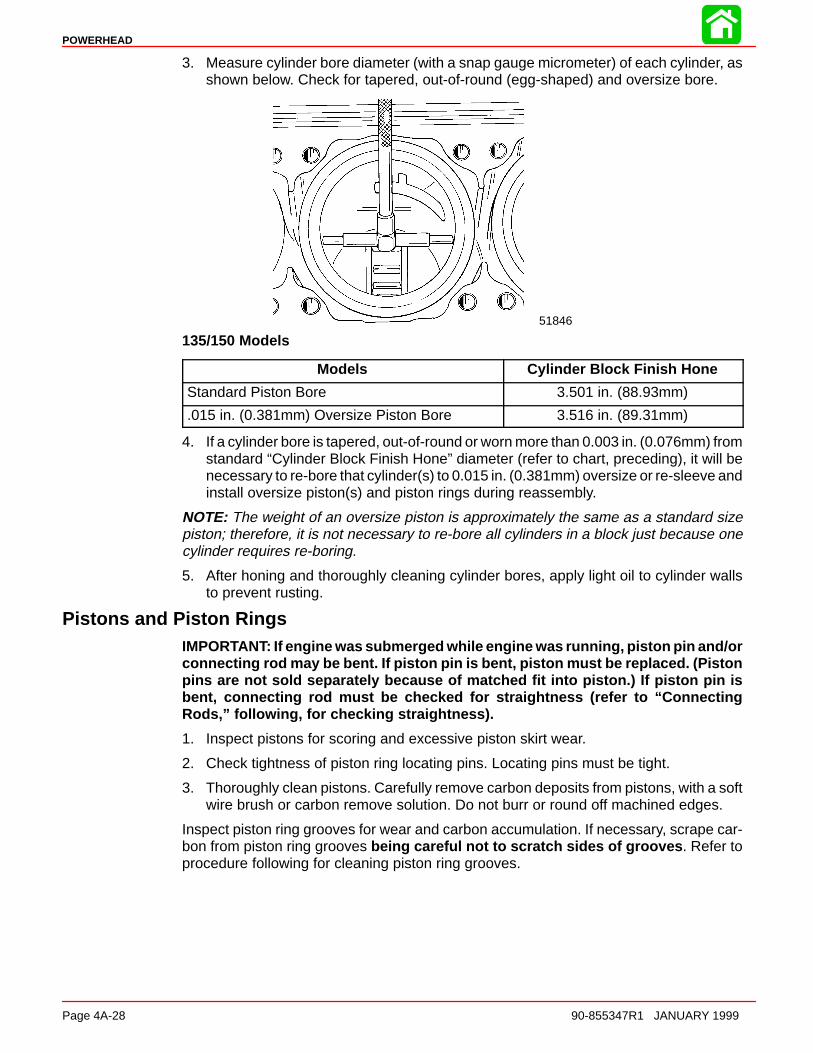
POWERHEAD
Page 4A-28 90-855347R1 JANUARY 1999
3. Measure cylinder bore diameter (with a snap gauge micrometer) of each cylinder, asshown below. Check for tapered, out-of-round (egg-shaped) and oversize bore.
51846
135/150 Models
Models Cylinder Block Finish Hone
Standard Piston Bore 3.501 in. (88.93mm)
.015 in. (0.381mm) Oversize Piston Bore 3.516 in. (89.31mm)
4. If a cylinder bore is tapered, out-of-round or worn more than 0.003 in. (0.076mm) fromstandard “Cylinder Block Finish Hone” diameter (refer to chart, preceding), it will benecessary to re-bore that cylinder(s) to 0.015 in. (0.381mm) oversize or re-sleeve andinstall oversize piston(s) and piston rings during reassembly.
NOTE: The weight of an oversize piston is approximately the same as a standard sizepiston; therefore, it is not necessary to re-bore all cylinders in a block just because onecylinder requires re-boring.
5. After honing and thoroughly cleaning cylinder bores, apply light oil to cylinder wallsto prevent rusting.
Pistons and Piston RingsIMPORTANT: If engine was submerged while engine was running, piston pin and/orconnecting rod may be bent. If piston pin is bent, piston must be replaced. (Pistonpins are not sold separately because of matched fit into piston.) If piston pin isbent, connecting rod must be checked for straightness (refer to “ConnectingRods,” following, for checking straightness).
1. Inspect pistons for scoring and excessive piston skirt wear.
2. Check tightness of piston ring locating pins. Locating pins must be tight.
3. Thoroughly clean pistons. Carefully remove carbon deposits from pistons, with a softwire brush or carbon remove solution. Do not burr or round off machined edges.
Inspect piston ring grooves for wear and carbon accumulation. If necessary, scrape car-bon from piston ring grooves being careful not to scratch sides of grooves . Refer toprocedure following for cleaning piston ring grooves.

POWERHEAD
90-855347R1 JANUARY 1999 Page 4A-29
CLEANING PISTON RING GROOVES
Keystone (tapered) ring grooves
CAUTIONCare must be taken not to scratch the side surfaces of the ring groove. Scratchingthe side surface of the ring groove will damage the ring groove.
1. Use a bristle brush and carbon remover solution to remove carbon from side surfaces.
2. A tool can be made for cleaning the inner diameter of the tapered ring grooves. Thetool can be made from a broken tapered piston ring with the side taper removed toenable the inside edge of the ring to reach the inner diameter of the groove. Carefullyscrape carbon from inner diameter of ring grooves. Care must be taken not to damagethe grooves by scratching the side surfaces of the grooves.
Piston with two half keystone (half tapered) rings (135/150 Models)
Enlarged View ofPiston Ring Grooves
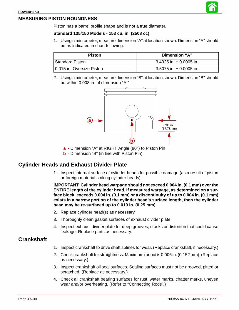
POWERHEAD
Page 4A-30 90-855347R1 JANUARY 1999
MEASURING PISTON ROUNDNESS
Piston has a barrel profile shape and is not a true diameter.
Standard 135/150 Models - 153 cu. in. (2508 cc)
1. Using a micrometer, measure dimension “A” at location shown. Dimension “A” shouldbe as indicated in chart following.
Piston Dimension “A”
Standard Piston 3.4925 in. ± 0.0005 in.
0.015 in. Oversize Piston 3.5075 in. ± 0.0005 in.
2. Using a micrometer, measure dimension “B” at location shown. Dimension “B” shouldbe within 0.008 in. of dimension “A.”
0.700 in.(17.78mm)
a
b
a - Dimension “A” at RIGHT Angle (90°) to Piston Pinb - Dimension “B” (in line with Piston Pin)
Cylinder Heads and Exhaust Divider Plate1. Inspect internal surface of cylinder heads for possible damage (as a result of piston
or foreign material striking cylinder heads).
IMPORTANT: Cylinder head warpage should not exceed 0.004 in. (0.1 mm) over theENTIRE length of the cylinder head. If measured warpage, as determined on a sur-face block, exceeds 0.004 in. (0.1 mm) or a discontinuity of up to 0.004 in. (0.1 mm)exists in a narrow portion of the cylinder head’s surface length, then the cylinderhead may be re-surfaced up to 0.010 in. (0.25 mm).
2. Replace cylinder head(s) as necessary.
3. Thoroughly clean gasket surfaces of exhaust divider plate.
4. Inspect exhaust divider plate for deep grooves, cracks or distortion that could causeleakage. Replace parts as necessary.
Crankshaft1. Inspect crankshaft to drive shaft splines for wear. (Replace crankshaft, if necessary.)
2. Check crankshaft for straightness. Maximum runout is 0.006 in. (0.152 mm). (Replaceas necessary.)
3. Inspect crankshaft oil seal surfaces. Sealing surfaces must not be grooved, pitted orscratched. (Replace as necessary.)
4. Check all crankshaft bearing surfaces for rust, water marks, chatter marks, unevenwear and/or overheating. (Refer to “Connecting Rods”.)

POWERHEAD
90-855347R1 JANUARY 1999 Page 4A-31
5. If necessary, clean crankshaft surfaces with crocus cloth.
51847
a b
cc
a - Crankshaft Journalsb - Crocus Clothc - Work Cloth “Back-and-Forth”
WARNINGDO NOT spin-dry crankshaft ball bearing with compressed air.
6. Thoroughly clean (with solvent) and dry crankshaft and crankshaft ball bearing. Re-check surfaces of crankshaft. Replace crankshaft, if surfaces cannot be properly“cleaned up.” If crankshaft will be re-used, lubricate surfaces of crankshaft with lightoil to prevent rust. DO NOT lubricate crankshaft ball bearing at this time.
Crankshaft (and End Cap) Bearings1. After cleaning crankshaft, grasp outer race of crankshaft ball bearing (installed on low-
er end of crankshaft) and attempt to work race back-and-forth. There should not beexcessive play.
2. Lubricate ball bearing with light oil. Rotate outer bearing race. Bearing should havesmooth action and no rust stains. If ball bearing sounds or feels “rough” or has“catches,” remove and discard bearing. (Refer to “Powerhead Removal and Disas-sembly - Crankshaft Removal and Disassembly”.)
Lower Ball Bearing
3. Thoroughly clean (with solvent) and dry crankshaft center main roller bearings. Lubri-cate bearings with 2-Cycle Outboard Oil.
CAUTIONDO NOT intermix halves of upper and lower crankshaft center main roller bear-ings. Replace bearings in pairs only.
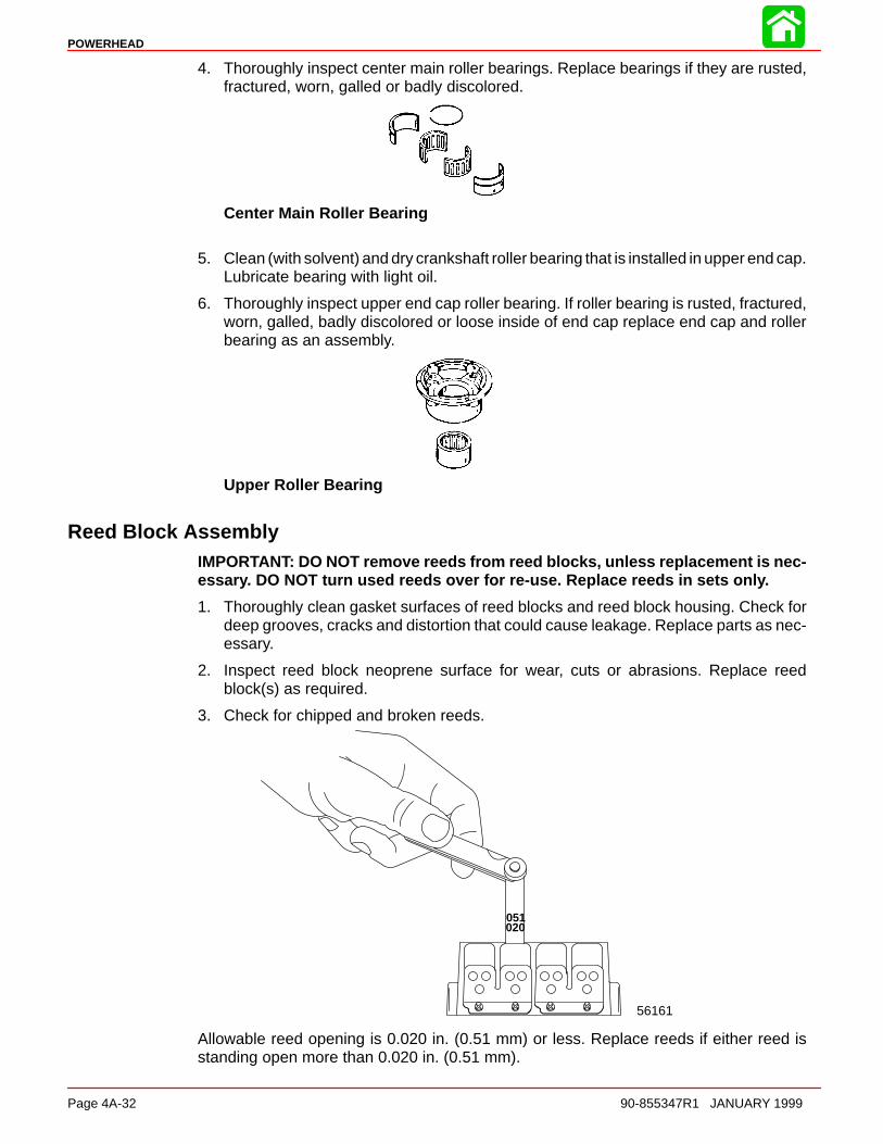
POWERHEAD
Page 4A-32 90-855347R1 JANUARY 1999
4. Thoroughly inspect center main roller bearings. Replace bearings if they are rusted,fractured, worn, galled or badly discolored.
Center Main Roller Bearing
5. Clean (with solvent) and dry crankshaft roller bearing that is installed in upper end cap.Lubricate bearing with light oil.
6. Thoroughly inspect upper end cap roller bearing. If roller bearing is rusted, fractured,worn, galled, badly discolored or loose inside of end cap replace end cap and rollerbearing as an assembly.
Upper Roller Bearing
Reed Block AssemblyIMPORTANT: DO NOT remove reeds from reed blocks, unless replacement is nec-essary. DO NOT turn used reeds over for re-use. Replace reeds in sets only.
1. Thoroughly clean gasket surfaces of reed blocks and reed block housing. Check fordeep grooves, cracks and distortion that could cause leakage. Replace parts as nec-essary.
2. Inspect reed block neoprene surface for wear, cuts or abrasions. Replace reedblock(s) as required.
3. Check for chipped and broken reeds.
020051
56161
Allowable reed opening is 0.020 in. (0.51 mm) or less. Replace reeds if either reed isstanding open more than 0.020 in. (0.51 mm).
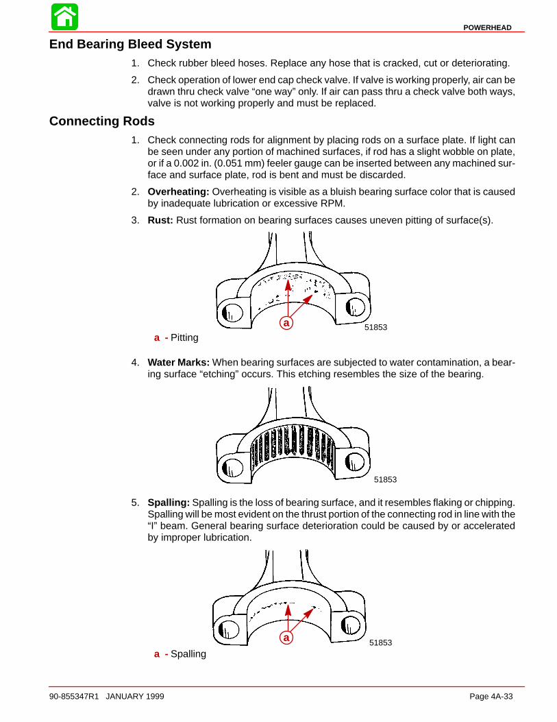
POWERHEAD
90-855347R1 JANUARY 1999 Page 4A-33
End Bearing Bleed System1. Check rubber bleed hoses. Replace any hose that is cracked, cut or deteriorating.
2. Check operation of lower end cap check valve. If valve is working properly, air can bedrawn thru check valve “one way” only. If air can pass thru a check valve both ways,valve is not working properly and must be replaced.
Connecting Rods1. Check connecting rods for alignment by placing rods on a surface plate. If light can
be seen under any portion of machined surfaces, if rod has a slight wobble on plate,or if a 0.002 in. (0.051 mm) feeler gauge can be inserted between any machined sur-face and surface plate, rod is bent and must be discarded.
2. Overheating: Overheating is visible as a bluish bearing surface color that is causedby inadequate lubrication or excessive RPM.
3. Rust: Rust formation on bearing surfaces causes uneven pitting of surface(s).
51853aa - Pitting
4. Water Marks: When bearing surfaces are subjected to water contamination, a bear-ing surface “etching” occurs. This etching resembles the size of the bearing.
51853
5. Spalling: Spalling is the loss of bearing surface, and it resembles flaking or chipping.Spalling will be most evident on the thrust portion of the connecting rod in line with the“I” beam. General bearing surface deterioration could be caused by or acceleratedby improper lubrication.
51853aa - Spalling
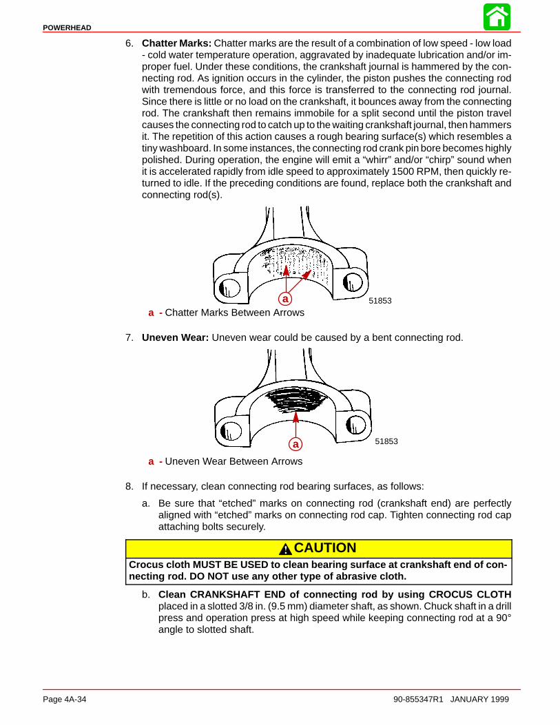
POWERHEAD
Page 4A-34 90-855347R1 JANUARY 1999
6. Chatter Marks: Chatter marks are the result of a combination of low speed - low load- cold water temperature operation, aggravated by inadequate lubrication and/or im-proper fuel. Under these conditions, the crankshaft journal is hammered by the con-necting rod. As ignition occurs in the cylinder, the piston pushes the connecting rodwith tremendous force, and this force is transferred to the connecting rod journal.Since there is little or no load on the crankshaft, it bounces away from the connectingrod. The crankshaft then remains immobile for a split second until the piston travelcauses the connecting rod to catch up to the waiting crankshaft journal, then hammersit. The repetition of this action causes a rough bearing surface(s) which resembles atiny washboard. In some instances, the connecting rod crank pin bore becomes highlypolished. During operation, the engine will emit a “whirr” and/or “chirp” sound whenit is accelerated rapidly from idle speed to approximately 1500 RPM, then quickly re-turned to idle. If the preceding conditions are found, replace both the crankshaft andconnecting rod(s).
a 51853aa - Chatter Marks Between Arrows
7. Uneven Wear: Uneven wear could be caused by a bent connecting rod.
a 51853a
a - Uneven Wear Between Arrows
8. If necessary, clean connecting rod bearing surfaces, as follows:
a. Be sure that “etched” marks on connecting rod (crankshaft end) are perfectlyaligned with “etched” marks on connecting rod cap. Tighten connecting rod capattaching bolts securely.
CAUTIONCrocus cloth MUST BE USED to clean bearing surface at crankshaft end of con-necting rod. DO NOT use any other type of abrasive cloth.
b. Clean CRANKSHAFT END of connecting rod by using CROCUS CLOTHplaced in a slotted 3/8 in. (9.5 mm) diameter shaft, as shown. Chuck shaft in a drillpress and operation press at high speed while keeping connecting rod at a 90°angle to slotted shaft.
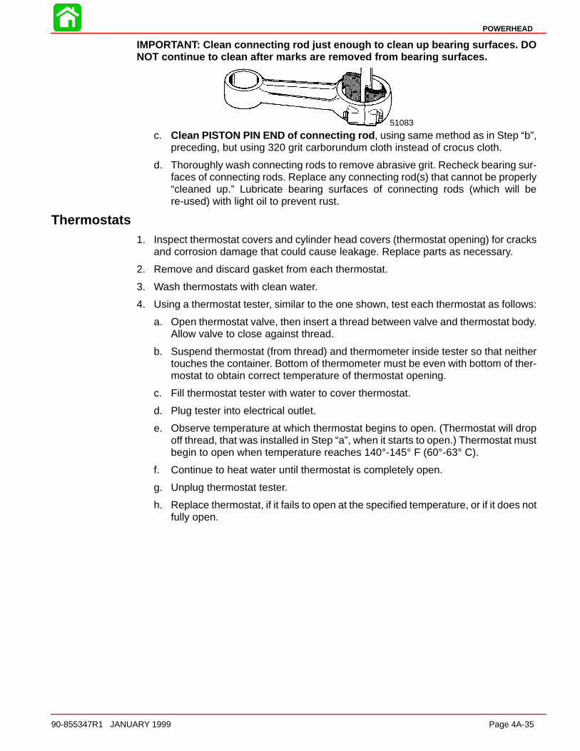
POWERHEAD
90-855347R1 JANUARY 1999 Page 4A-35
IMPORTANT: Clean connecting rod just enough to clean up bearing surfaces. DONOT continue to clean after marks are removed from bearing surfaces.
51083
c. Clean PISTON PIN END of connecting rod , using same method as in Step “b”,preceding, but using 320 grit carborundum cloth instead of crocus cloth.
d. Thoroughly wash connecting rods to remove abrasive grit. Recheck bearing sur-faces of connecting rods. Replace any connecting rod(s) that cannot be properly“cleaned up.” Lubricate bearing surfaces of connecting rods (which will bere-used) with light oil to prevent rust.
Thermostats1. Inspect thermostat covers and cylinder head covers (thermostat opening) for cracks
and corrosion damage that could cause leakage. Replace parts as necessary.
2. Remove and discard gasket from each thermostat.
3. Wash thermostats with clean water.
4. Using a thermostat tester, similar to the one shown, test each thermostat as follows:
a. Open thermostat valve, then insert a thread between valve and thermostat body.Allow valve to close against thread.
b. Suspend thermostat (from thread) and thermometer inside tester so that neithertouches the container. Bottom of thermometer must be even with bottom of ther-mostat to obtain correct temperature of thermostat opening.
c. Fill thermostat tester with water to cover thermostat.
d. Plug tester into electrical outlet.
e. Observe temperature at which thermostat begins to open. (Thermostat will dropoff thread, that was installed in Step “a”, when it starts to open.) Thermostat mustbegin to open when temperature reaches 140°-145° F (60°-63° C).
f. Continue to heat water until thermostat is completely open.
g. Unplug thermostat tester.
h. Replace thermostat, if it fails to open at the specified temperature, or if it does notfully open.

POWERHEAD
Page 4A-36 90-855347R1 JANUARY 1999
NOTE: BE SURE that water in thermostat tester is allowed to cool sufficiently [below 130°F (56° C)] before testing the other thermostat.
51087
Powerhead Reassembly and Installation
GeneralBefore proceeding with powerhead reassembly, be sure that all parts to be re-used havebeen carefully cleaned and thoroughly inspected, as outlined in “Cleaning and Inspec-tion,” preceding. Parts, which have not been properly cleaned (or which are question-able), can severely damage an otherwise perfectly good powerhead within the first fewminutes of operation. All new powerhead gaskets MUST BE installed during reassembly.
During reassembly, lubricate parts with Quicksilver 2-Cycle Outboard Lubricant when-ever “light oil” is specified. Quicksilver part numbers of lubricants, sealers and lockingcompounds and tools are listed in “Powerhead General Information,” preceding.
A torque wrench is essential for correct reassembly of powerhead. DO NOT attempt toreassemble powerhead without using a torque wrench. Attaching bolts for covers, hous-ings and cylinder heads MUST BE torqued by tightening bolts in 3 progressive steps (fol-lowing specified torque sequence) until specified torque is reached (see “Example,” fol-lowing).
EXAMPLE: If cylinder head attaching bolts require a torque of 30 Ib. ft. (41 N·m), a) tightenall bolts to 10 Ib. ft. (13.5 N·m) , following specified torque sequence, b) tighten all boltsto 20 Ib. ft. (27 N·m) , following torque sequence, then finally c) tighten all bolts to 30 Ib.ft. (41 N·m) , following torque sequence.
1. If removed, press lower crankshaft ball bearing onto crankshaft as shown. Be surebearing is pressed firmly against counterweight.
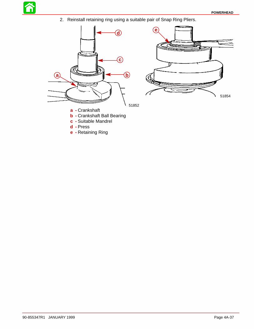
POWERHEAD
90-855347R1 JANUARY 1999 Page 4A-37
2. Reinstall retaining ring using a suitable pair of Snap Ring Pliers.
51854
51852
a b
c
de
a - Crankshaftb - Crankshaft Ball Bearingc - Suitable Mandreld - Presse - Retaining Ring

POWERHEAD
Page 4A-38 90-855347R1 JANUARY 1999
3. If removed, spread new crankshaft sealing rings just enough to slide over crankshaftjournal.
4. Use Piston Ring Expander (91-24697) and install crankshaft sealing rings intogroove.
5184951854
a
a - Crankshaft Sealing Rings
5. Lubricate center main crankshaft roller bearings and races with light oil.
51854a b
14 2 Cycle Outboard Oil (92-826666A24)
14
a - Install so LARGER of the 3 holes is toward DRIVE SHAFT end of crankshaftb - Verify retaining ring bridges the separating lines of the bearing race
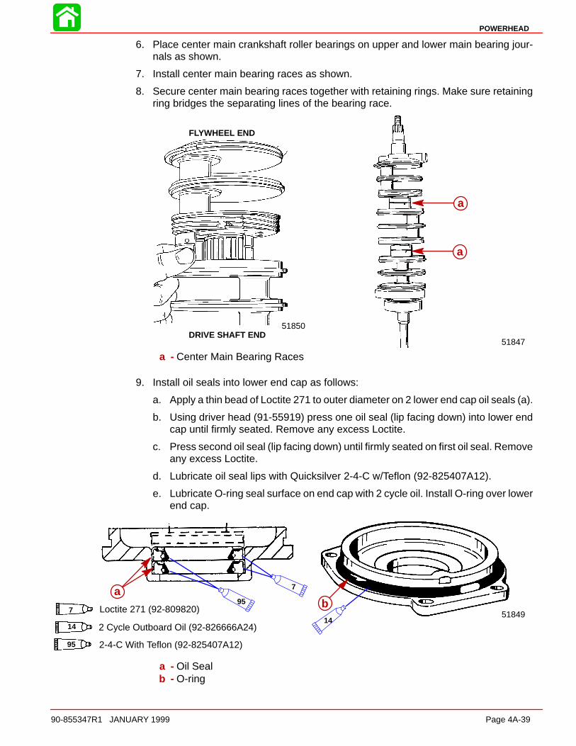
POWERHEAD
90-855347R1 JANUARY 1999 Page 4A-39
6. Place center main crankshaft roller bearings on upper and lower main bearing jour-nals as shown.
7. Install center main bearing races as shown.
8. Secure center main bearing races together with retaining rings. Make sure retainingring bridges the separating lines of the bearing race.
51847
FLYWHEEL END
DRIVE SHAFT END51850
a
a
a - Center Main Bearing Races
9. Install oil seals into lower end cap as follows:
a. Apply a thin bead of Loctite 271 to outer diameter on 2 lower end cap oil seals (a).
b. Using driver head (91-55919) press one oil seal (lip facing down) into lower endcap until firmly seated. Remove any excess Loctite.
c. Press second oil seal (lip facing down) until firmly seated on first oil seal. Removeany excess Loctite.
d. Lubricate oil seal lips with Quicksilver 2-4-C w/Teflon (92-825407A12).
e. Lubricate O-ring seal surface on end cap with 2 cycle oil. Install O-ring over lowerend cap.
51849b
a
7 Loctite 271 (92-809820)
7
14 2 Cycle Outboard Oil (92-826666A24)14
95 2-4-C With Teflon (92-825407A12)
95
a - Oil Sealb - O-ring
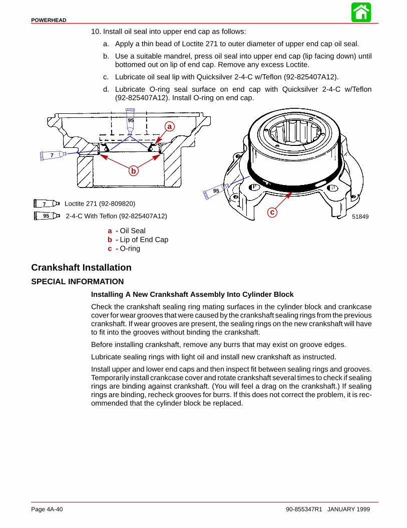
POWERHEAD
Page 4A-40 90-855347R1 JANUARY 1999
10. Install oil seal into upper end cap as follows:
a. Apply a thin bead of Loctite 271 to outer diameter of upper end cap oil seal.
b. Use a suitable mandrel, press oil seal into upper end cap (lip facing down) untilbottomed out on lip of end cap. Remove any excess Loctite.
c. Lubricate oil seal lip with Quicksilver 2-4-C w/Teflon (92-825407A12).
d. Lubricate O-ring seal surface on end cap with Quicksilver 2-4-C w/Teflon(92-825407A12). Install O-ring on end cap.
a 51849c
aa
b
7 Loctite 271 (92-809820)
95 2-4-C With Teflon (92-825407A12)
95
7
95
a - Oil Sealb - Lip of End Capc - O-ring
Crankshaft InstallationSPECIAL INFORMATION
Installing A New Crankshaft Assembly Into Cylinder Block
Check the crankshaft sealing ring mating surfaces in the cylinder block and crankcasecover for wear grooves that were caused by the crankshaft sealing rings from the previouscrankshaft. If wear grooves are present, the sealing rings on the new crankshaft will haveto fit into the grooves without binding the crankshaft.
Before installing crankshaft, remove any burrs that may exist on groove edges.
Lubricate sealing rings with light oil and install new crankshaft as instructed.
Install upper and lower end caps and then inspect fit between sealing rings and grooves.Temporarily install crankcase cover and rotate crankshaft several times to check if sealingrings are binding against crankshaft. (You will feel a drag on the crankshaft.) If sealingrings are binding, recheck grooves for burrs. If this does not correct the problem, it is rec-ommended that the cylinder block be replaced.

POWERHEAD
90-855347R1 JANUARY 1999 Page 4A-41
Install crankshaft as follows:
1. Lubricate crankshaft sealing rings with light oil.
2. Check cylinder block to be sure that dowel pins are in place.
51848
a
a - Dowel Pins
3. Position all crankshaft seal ring gaps straight up.
4. Align hole in each center main bearing race with dowel pin.
5. Gently push crankshaft down into position making sure that the dowel pins are linedup with the holes in center main bearings and crankshaft seal rings are in place.
6. Lubricate crankshaft ends (oil seal areas) with light oil, then install upper and lowerend caps (“a” and “b”). Secure end caps to cylinder block with attaching bolts. DO NOTtighten end cap bolts at this time.
51848
51848
bc
a
14 14
14 2 Cycle Outboard Oil (92-826666A24)
a - Dowel Pinb - Upper End Capc - Lower End Cap
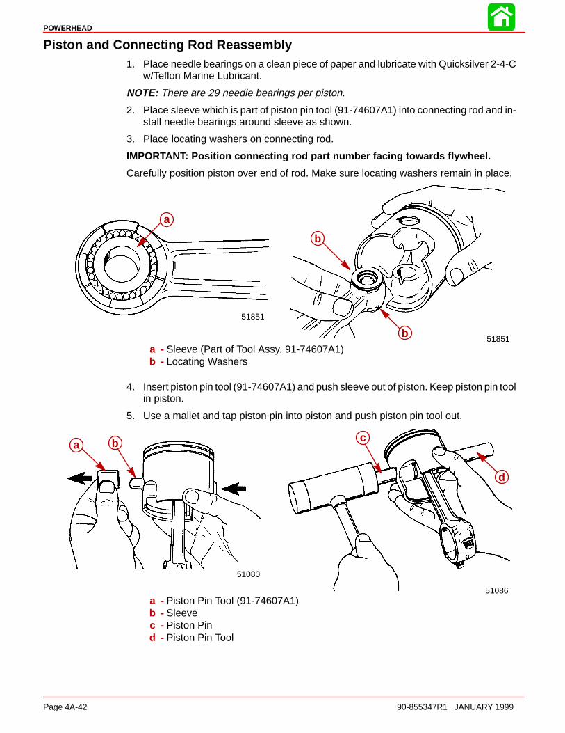
POWERHEAD
Page 4A-42 90-855347R1 JANUARY 1999
Piston and Connecting Rod Reassembly1. Place needle bearings on a clean piece of paper and lubricate with Quicksilver 2-4-C
w/Teflon Marine Lubricant.
NOTE: There are 29 needle bearings per piston.
2. Place sleeve which is part of piston pin tool (91-74607A1) into connecting rod and in-stall needle bearings around sleeve as shown.
3. Place locating washers on connecting rod.
IMPORTANT: Position connecting rod part number facing towards flywheel.
Carefully position piston over end of rod. Make sure locating washers remain in place.
51851
b
51851
b
a
a - Sleeve (Part of Tool Assy. 91-74607A1)b - Locating Washers
4. Insert piston pin tool (91-74607A1) and push sleeve out of piston. Keep piston pin toolin piston.
5. Use a mallet and tap piston pin into piston and push piston pin tool out.
51086
51080
c
d
a b
a - Piston Pin Tool (91-74607A1)b - Sleevec - Piston Pind - Piston Pin Tool

POWERHEAD
90-855347R1 JANUARY 1999 Page 4A-43
6. Install new piston pin lockrings (one each end of piston pin) with Lockring InstallationTool (91-77109A1).
7. Make sure lockrings are properly seated in piston grooves.
5108651086
a
a
b
a - Lockring Installation Tool (91-77109A1)b - Lockring
Piston and Piston Ring Combinations153 CU. IN. (2508 cc) MODELS
All 153 cu. in. (2508 cc) models have two half keystone (half tapered) rings.
Pistons with two half keystone (half tapered) rings
0.056 in. (1.4 mm)
0.056 in. (1.4 mm)
a b
a - Half Keystone (half tapered) Piston Ringb - Enlarged View of Piston Ring Grooves
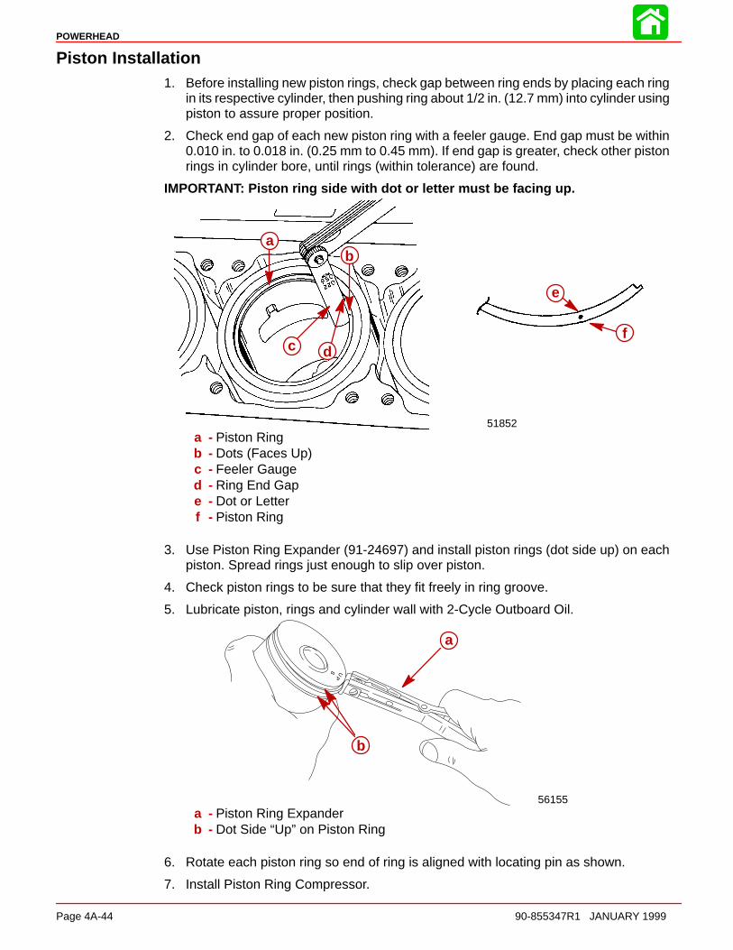
POWERHEAD
Page 4A-44 90-855347R1 JANUARY 1999
Piston Installation1. Before installing new piston rings, check gap between ring ends by placing each ring
in its respective cylinder, then pushing ring about 1/2 in. (12.7 mm) into cylinder usingpiston to assure proper position.
2. Check end gap of each new piston ring with a feeler gauge. End gap must be within0.010 in. to 0.018 in. (0.25 mm to 0.45 mm). If end gap is greater, check other pistonrings in cylinder bore, until rings (within tolerance) are found.
IMPORTANT: Piston ring side with dot or letter must be facing up.
51852
ba
c d
e
f
a - Piston Ringb - Dots (Faces Up)c - Feeler Gauged - Ring End Gape - Dot or Letterf - Piston Ring
3. Use Piston Ring Expander (91-24697) and install piston rings (dot side up) on eachpiston. Spread rings just enough to slip over piston.
4. Check piston rings to be sure that they fit freely in ring groove.
5. Lubricate piston, rings and cylinder wall with 2-Cycle Outboard Oil.
56155
b
aa
b
a - Piston Ring Expanderb - Dot Side “Up” on Piston Ring
6. Rotate each piston ring so end of ring is aligned with locating pin as shown.
7. Install Piston Ring Compressor.

POWERHEAD
90-855347R1 JANUARY 1999 Page 4A-45
8. Remove screws and connecting rod cap from piston rod assembly being installed.
IMPORTANT: Piston must be correctly installed and positioned as shown.
Pistons marked with the word “UP” and with the letter “P” or “S” on top of piston.
Pistons with the letter “P” must be installed in the port side of engine and the word “UP”facing toward top of engine.
Pistons with the letter “S” must be installed in the star- board side of engine and the word“UP” toward top of engine.
9. Coat cylinder bore with 2-cycle oil. Match piston assembly with cylinder it was re-moved from, and position piston as described below. Push piston into cylinder.
56156
CYL 2
CYL 4
CYL 6
CYL 1
CYL 3
CYL 5
UP
P
UP
P
UP
P
UP
S
UP
S
UP
S
14
14 2 Cycle Outboard Oil (92-826666A24)
10. Apply Quicksilver 2-4-C w/Teflon to bearing surface of connecting rod and install bear-ing assembly, as shown.
11. Place connecting rod cap on connecting rod. Apply light oil to threads and face of con-necting rod bolts. Thread connecting rod bolts finger-tight while checking for correctalignment of the rod cap as shown.
IMPORTANT: Connecting rod and connecting rod caps are matched halves. Do nottorque screws before completing the following procedure.
• Run a pencil lightly over ground area.
• If pencil stops at fracture point, loosen bolts, retighten, and check again.
NOTE: If you still feel the fracture point, discard the rod.
12. Tighten connecting rod bolts (using a 5/16 in. - 12 point socket). First torque to 15 lb.in. (1.7 N·m) then 30 lb. ft. (41 N·m). Turn each bolt an additional 90° after 2nd torqueis attained. Recheck alignment between rod cap and rod as shown.
aa
51850
aa
95 2-4-C With Teflon (92-825407A12)
95
a - Connecting Rod Screws

POWERHEAD
Page 4A-46 90-855347R1 JANUARY 1999
13. Rotate crankshaft several times (using powerhead stand) to assure free operation(no binds and catching).
Connecting Rod Cap AlignmentCheck each connecting rod cap for correct alignment. If not aligned, a ridge can be seenor felt at the separating line as shown below. Correct any misalignment.
ÄÄÄÄÄÄ
ÄÄÄÄ
Side ViewCorrect
End ViewCorrect
Side ViewIncorrect-Capon Backwards
End ViewIncorrect-Capon Backwards
ÄÄÄÄÄÄÄÄ
End ViewIncorrect-
Not Aligned
14. Verify that no piston rings were broken during installation by pressing in on each pistonring thru exhaust port using a screwdriver. If no spring tension exists (ring fails to re-turn to position), it’s likely ring is broken and must be replaced.
51852
a
a - Screwdriver
Crankcase Cover Installation1. Thoroughly remove all oil from mating surfaces of crankcase cover and cylinder block
with Loctite 7649 Primer (92-809824).
2. Install gasket strips into grooves in crankcase cover. Trim end of each gasket stripflush with edge of cover as shown.
51852
a b
a - Gasket Stripsb - Edge of Cover

POWERHEAD
90-855347R1 JANUARY 1999 Page 4A-47
3. Apply a thin, even coat of Loctite Master Gasket #203 on mating surfaces of crank-case cover and cylinder block.
4. Place crankcase cover in position on cylinder block. Turn the 8 center main bolts ina LITTLE at a time, (following torque sequence) compressing crankshaft seal ringsuntil crankshaft cover has been drawn down to cylinder block. Tighten eight bolts (a)evenly in three progressive steps (following torque sequence).
5. Install remaining crankcase cover flange bolts.
6. Tighten end cap bolts to specified torque.
8 7
4
2
65
3
1
51846
b
c
d
e
12 Loctite Master Gasket (92-12564-2)
12
a
a - Loctite Master Gasket (92-12564-2)b - Upper End Cap Bolts – Torque to 150 lb. in. (17 N·m)c - Lower End Cap Bolts – Torque to 80 lb. in. (9 N·m)d - Add Light Oil to Threads and Bolt Face – 8 Bolts (3/8 in.-18)
Torque to 38 lb. ft. (51.5 N·m)e - Bolts (5/16 in.-18) Torque to 180 lb. in. (20 N·m)
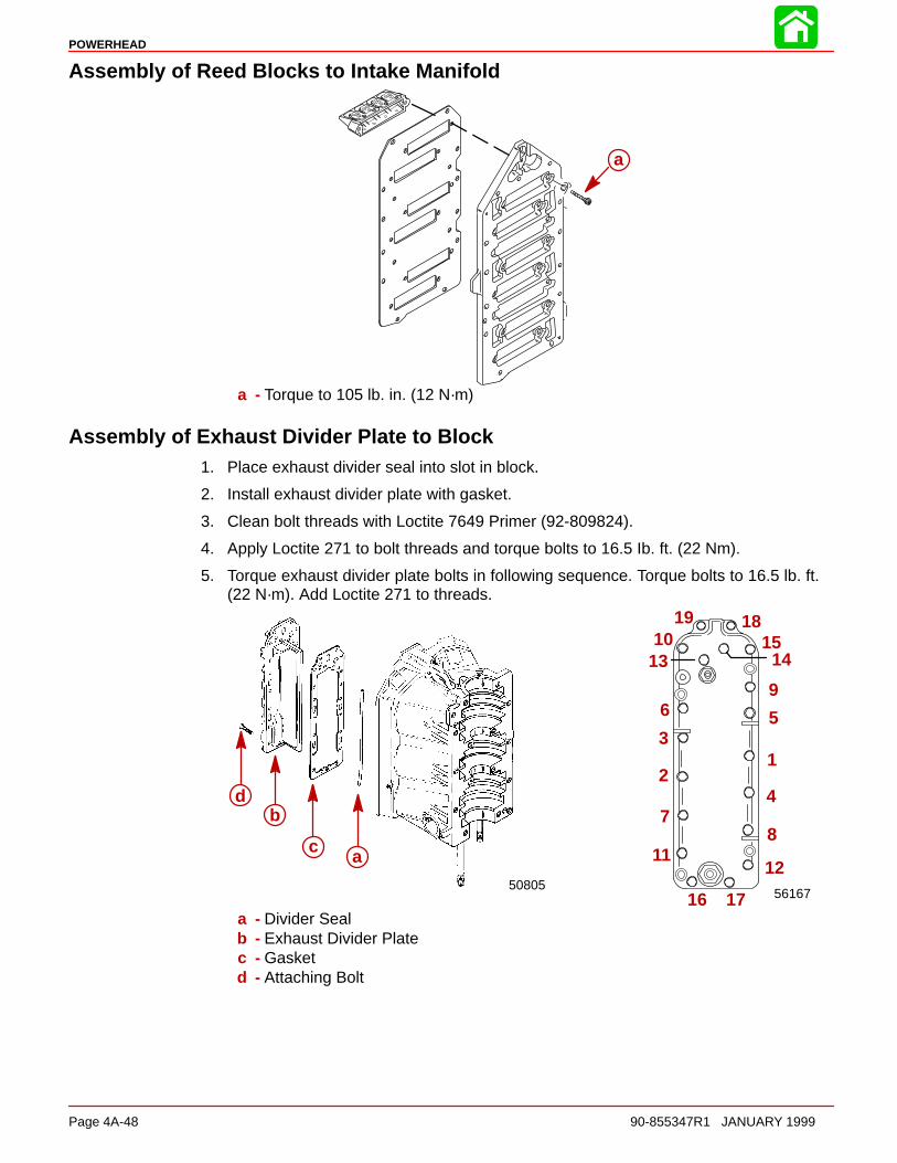
POWERHEAD
Page 4A-48 90-855347R1 JANUARY 1999
Assembly of Reed Blocks to Intake Manifold
aa
a - Torque to 105 lb. in. (12 N·m)
Assembly of Exhaust Divider Plate to Block1. Place exhaust divider seal into slot in block.
2. Install exhaust divider plate with gasket.
3. Clean bolt threads with Loctite 7649 Primer (92-809824).
4. Apply Loctite 271 to bolt threads and torque bolts to 16.5 Ib. ft. (22 Nm).
5. Torque exhaust divider plate bolts in following sequence. Torque bolts to 16.5 lb. ft.(22 N·m). Add Loctite 271 to threads.
56167
12
3
4
56
78
9
1112
13 1415
16 17
181910
50805
a
b
c
d
a - Divider Sealb - Exhaust Divider Platec - Gasketd - Attaching Bolt

POWERHEAD
90-855347R1 JANUARY 1999 Page 4A-49
6. If removed, install water pressure relief valve components as shown. Torque bolts tospecifications.
2
1
38
54
9
1011
12
76
3
13
50803
1 - Cover2 - Bolt - 150 lb. in. (17 N·m)3 - Gasket4 - Relief Valve Plate5 - Diaphragm6 - Water Deflector7 - Washer8 - Screw - 25 lb. in. (3 N·m)9 - Spring
10 - Poppet Valve11 - Grommet12 - Carrier13 - Washer
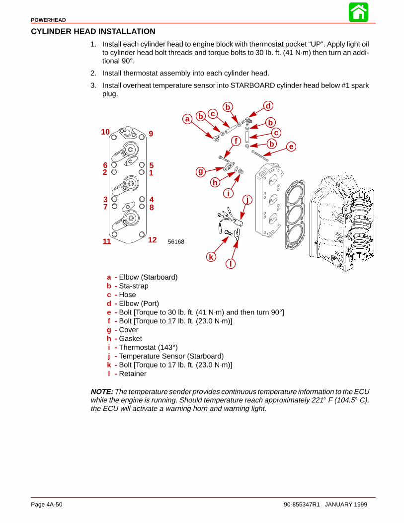
POWERHEAD
Page 4A-50 90-855347R1 JANUARY 1999
CYLINDER HEAD INSTALLATION
1. Install each cylinder head to engine block with thermostat pocket “UP”. Apply light oilto cylinder head bolt threads and torque bolts to 30 Ib. ft. (41 N·m) then turn an addi-tional 90°.
2. Install thermostat assembly into each cylinder head.
3. Install overheat temperature sensor into STARBOARD cylinder head below #1 sparkplug.
56168
12
3 4
56
7 8
910
11 12
a bb
b
b
c
c
d
ef
gh
ij
kl
a - Elbow (Starboard)b - Sta-strapc - Hosed - Elbow (Port)e - Bolt [Torque to 30 lb. ft. (41 N·m) and then turn 90°]f - Bolt [Torque to 17 lb. ft. (23.0 N·m)]g - Coverh - Gasketi - Thermostat (143°)j - Temperature Sensor (Starboard)k - Bolt [Torque to 17 lb. ft. (23.0 N·m)]l - Retainer
NOTE: The temperature sender provides continuous temperature information to the ECUwhile the engine is running. Should temperature reach approximately 221° F (104.5° C),the ECU will activate a warning horn and warning light.

POWERHEAD
90-855347R1 JANUARY 1999 Page 4A-51
4. Thermostat and temperature sensor installed.
56163 56164
a
b
a - Thermostat (143° F 61.7° C)b - Overheat Temperature Sensor
NOTE: When installing thermostat hoses, secure starboard to port thermostat hose (a)with sta-straps (b) to prevent hose from being cut by alternator/air compressor belt.
ab
Reinstalling Engine Components
Reinstall the following engine components:
Section 2Starter MotorElectronic Control ModuleIgnition CoilStarter SolenoidAlternatorFlywheel
Section 3Direct Fuel InjectionFuel PumpOn-Board Oil TankOil Pump
Section 7Shift Cable Latch AssemblyControl Cable Anchor Bracket
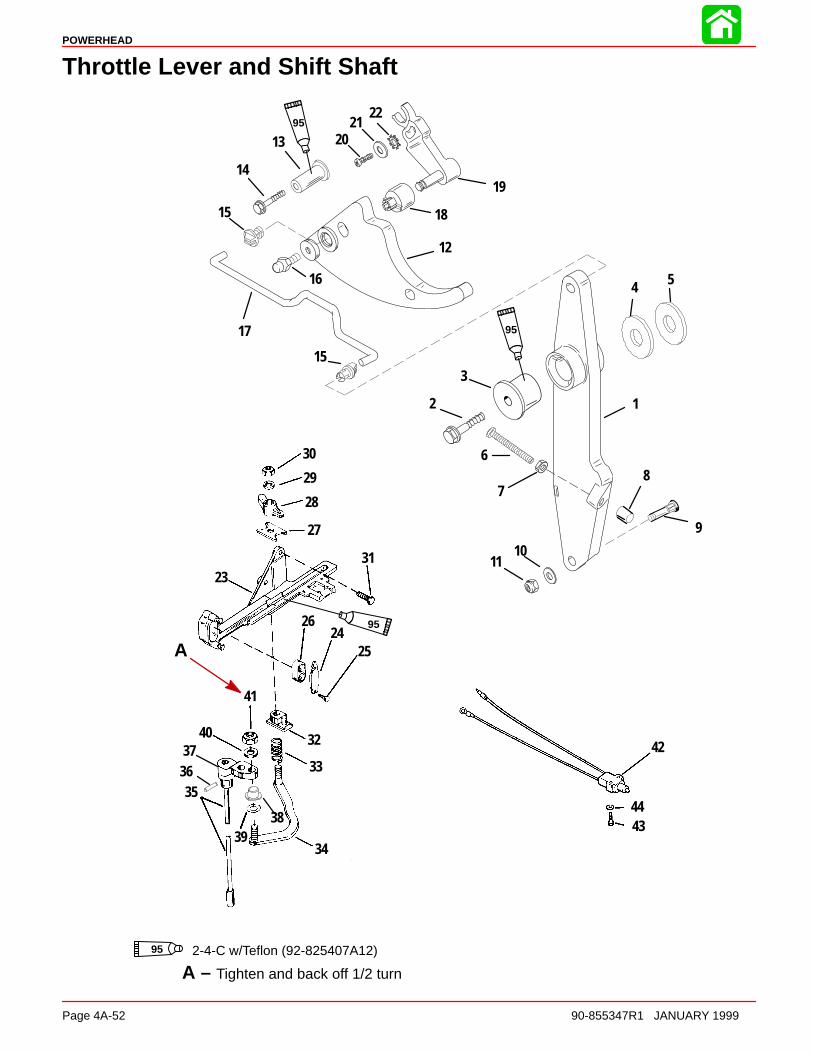
POWERHEAD
Page 4A-52 90-855347R1 JANUARY 1999
Throttle Lever and Shift Shaft
16
17
14
18
19
12
3
6
78
9
1110
12
13
15
36
23
2425
26
27
28
29
30
31
32
33
3439
38
40
41
4344
42
35
37
15
2122
2095
95
95
4 5
95 2-4-C w/Teflon (92-825407A12)
A
A – Tighten and back off 1/2 turn

POWERHEAD
90-855347R1 JANUARY 1999 Page 4A-53
Throttle Lever and Shift Shaft
REF. TORQUEREF.NO. QTY. DESCRIPTION lb-in lb-ft Nm.
1 1 THROTTLE CONTROL LEVER
2 1 SCREW (.375-16 x 1-3/4 IN.) 240 20 27
3 1 BUSHING4 1 WASHER5 1 WASHER
6 1 SCREW (2-1/8 IN.)7 1 NUT (1/4-20)
8 1 CAP9 1 INSERT10 1 WASHER11 1 NUT 50 5.5
12 1 CAM13 1 BUSHING14 1 SCREW (M6 x 40) 45 5
15 2 SWIVEL BUSHING16 1 THREADED BALL Drive Tight17 1 LINK18 1 ROLLER19 1 THROTTLE ROLLER20 1 SCREW (M5 x 16) Drive Tight
21 1 WASHER
22 1 STAR WASHER23 1 ANCHOR BRACKET24 1 LATCH25 2 SCREW-Drive26 1 CAP27 1 WEAR PLATE
28 1 LATCH29 1 WASHER30 1 NUT
31 3 SCREW (.312-18 x 7/8) 160 18
32 1 GUIDE BLOCK33 1 SPRING34 1 LINK ROD ASSEMBLY
35 1 SHIFT SHAFT ASSEMBLY36 1 ROLL PIN37 1 SHIFT SHAFT LEVER–UPPER
38 1 BUSHING39 1 WAVE WASHER40 1 WASHER41 1 NUT
42 1 IDLE STABILIZING SHIFT KIT
43 2 SCREW (6-32) 15 1.7
44 2 WASHER
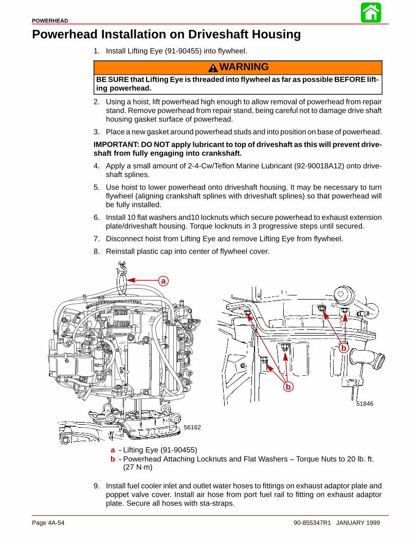
POWERHEAD
Page 4A-54 90-855347R1 JANUARY 1999
Powerhead Installation on Driveshaft Housing1. Install Lifting Eye (91-90455) into flywheel.
WARNINGBE SURE that Lifting Eye is threaded into flywheel as far as possible BEFORE lift-ing powerhead.
2. Using a hoist, lift powerhead high enough to allow removal of powerhead from repairstand. Remove powerhead from repair stand, being careful not to damage drive shafthousing gasket surface of powerhead.
3. Place a new gasket around powerhead studs and into position on base of powerhead.
IMPORTANT: DO NOT apply lubricant to top of driveshaft as this will prevent drive-shaft from fully engaging into crankshaft.
4. Apply a small amount of 2-4-Cw/Teflon Marine Lubricant (92-90018A12) onto drive-shaft splines.
5. Use hoist to lower powerhead onto driveshaft housing. It may be necessary to turnflywheel (aligning crankshaft splines with driveshaft splines) so that powerhead willbe fully installed.
6. Install 10 flat washers and10 locknuts which secure powerhead to exhaust extensionplate/driveshaft housing. Torque locknuts in 3 progressive steps until secured.
7. Disconnect hoist from Lifting Eye and remove Lifting Eye from flywheel.
8. Reinstall plastic cap into center of flywheel cover.
51846
b
b
56162
a
a - Lifting Eye (91-90455)b - Powerhead Attaching Locknuts and Flat Washers – Torque Nuts to 20 lb. ft.
(27 N·m)
9. Install fuel cooler inlet and outlet water hoses to fittings on exhaust adaptor plate andpoppet valve cover. Install air hose from port fuel rail to fitting on exhaust adaptorplate. Secure all hoses with sta-straps.
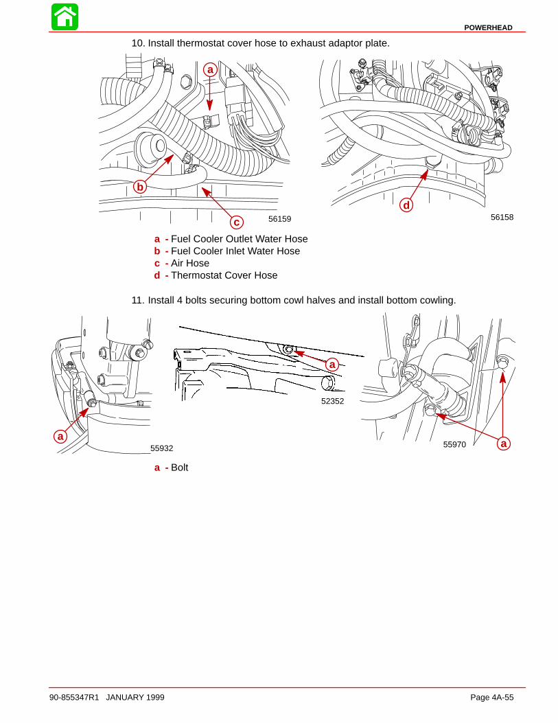
POWERHEAD
90-855347R1 JANUARY 1999 Page 4A-55
10. Install thermostat cover hose to exhaust adaptor plate.
56158d
56159
a
b
c
a - Fuel Cooler Outlet Water Hoseb - Fuel Cooler Inlet Water Hosec - Air Hosed - Thermostat Cover Hose
11. Install 4 bolts securing bottom cowl halves and install bottom cowling.
55970
52352
55932a
a
a
a - Bolt
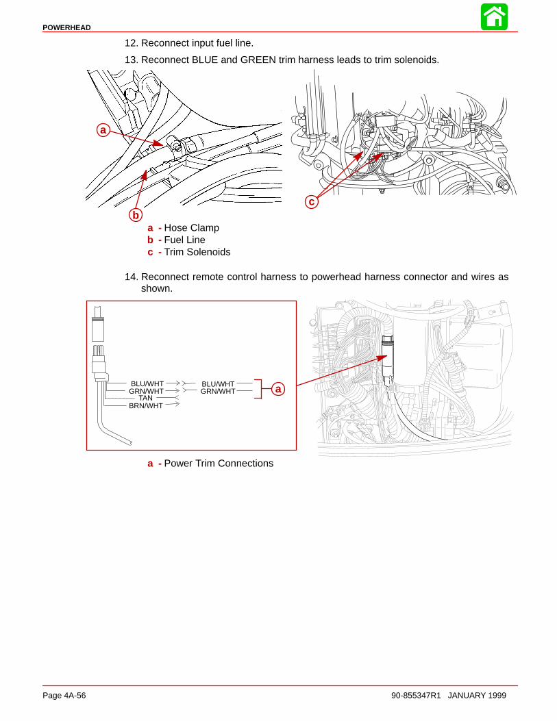
POWERHEAD
Page 4A-56 90-855347R1 JANUARY 1999
12. Reconnect input fuel line.
13. Reconnect BLUE and GREEN trim harness leads to trim solenoids.
ac
a
b
a
ba - Hose Clampb - Fuel Linec - Trim Solenoids
14. Reconnect remote control harness to powerhead harness connector and wires asshown.
GRN/WHTBLU/WHT
BRN/WHTTAN
BLU/WHTGRN/WHT aa
a - Power Trim Connections
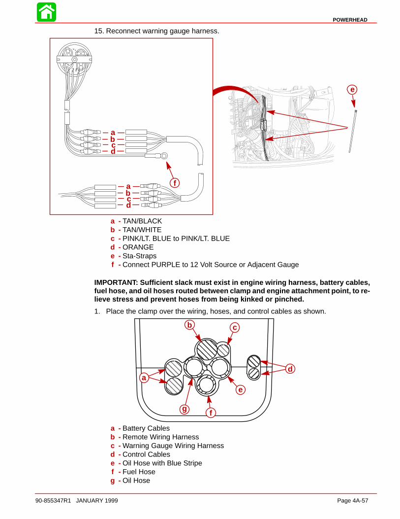
POWERHEAD
90-855347R1 JANUARY 1999 Page 4A-57
15. Reconnect warning gauge harness.
1
2 3 45
6
a
cb
d
a
cb
d
f
e
a - TAN/BLACKb - TAN/WHITEc - PINK/LT. BLUE to PINK/LT. BLUEd - ORANGEe - Sta-Strapsf - Connect PURPLE to 12 Volt Source or Adjacent Gauge
IMPORTANT: Sufficient slack must exist in engine wiring harness, battery cables,fuel hose, and oil hoses routed between clamp and engine attachment point, to re-lieve stress and prevent hoses from being kinked or pinched.
1. Place the clamp over the wiring, hoses, and control cables as shown.
ÇÇÇÇÇÇÇÇÇ
ÉÉÉÉÉÉÉÉÉ
ÇÇÇÇÇÇÇÇÇÇÇÇÇÇÇÇÇÇ
ÇÇÇÇÉÉÉÉ
ÇÇÇÇ
a
b c
d
e
fg
a - Battery Cablesb - Remote Wiring Harnessc - Warning Gauge Wiring Harnessd - Control Cablese - Oil Hose with Blue Stripef - Fuel Hoseg - Oil Hose
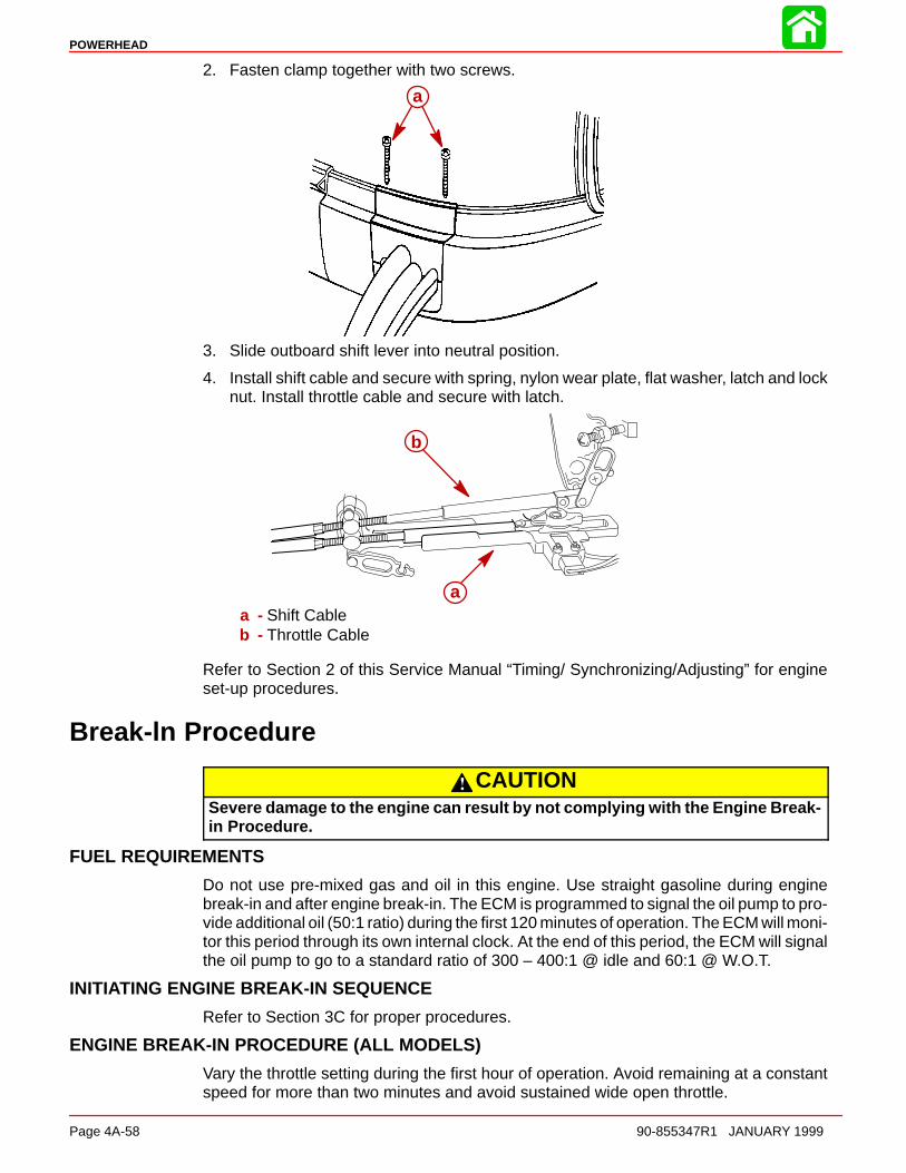
POWERHEAD
Page 4A-58 90-855347R1 JANUARY 1999
2. Fasten clamp together with two screws.
a
3. Slide outboard shift lever into neutral position.
4. Install shift cable and secure with spring, nylon wear plate, flat washer, latch and locknut. Install throttle cable and secure with latch.
a
b
a - Shift Cableb - Throttle Cable
Refer to Section 2 of this Service Manual “Timing/ Synchronizing/Adjusting” for engineset-up procedures.
Break-ln Procedure
CAUTIONSevere damage to the engine can result by not complying with the Engine Break-in Procedure.
FUEL REQUIREMENTS
Do not use pre-mixed gas and oil in this engine. Use straight gasoline during enginebreak-in and after engine break-in. The ECM is programmed to signal the oil pump to pro-vide additional oil (50:1 ratio) during the first 120 minutes of operation. The ECM will moni-tor this period through its own internal clock. At the end of this period, the ECM will signalthe oil pump to go to a standard ratio of 300 – 400:1 @ idle and 60:1 @ W.O.T.
INITIATING ENGINE BREAK-IN SEQUENCE
Refer to Section 3C for proper procedures.
ENGINE BREAK-IN PROCEDURE (ALL MODELS)
Vary the throttle setting during the first hour of operation. Avoid remaining at a constantspeed for more than two minutes and avoid sustained wide open throttle.

4B
COOLING
90-855347R1 JANUARY 1999 Page 4B-1
POWERHEADSection 4B - Cooling
Table of Contents
Specifications 4B-1. . . . . . . . . . . . . . . . . . . . . . . . . . . . . . . . Water Pressure 4B-1. . . . . . . . . . . . . . . . . . . . . . . . . . . Thermostat 4B-1. . . . . . . . . . . . . . . . . . . . . . . . . . . . . . .
Special Tools 4B-2. . . . . . . . . . . . . . . . . . . . . . . . . . . . . . . . Temperature Sensor 4B-3. . . . . . . . . . . . . . . . . . . . . . .
2.5 Liter Optimax/DFI Water Flow 4B-3. . . . . . . . . . . . . . Description 4B-3. . . . . . . . . . . . . . . . . . . . . . . . . . . . . . .
1998/1999 Water Flow Diagram 4B-5. . . . . . . . . . . . . . . . 1999 1/2 Water Flow Diagram 4B-6. . . . . . . . . . . . . . . . . Thermostat Test 4B-7. . . . . . . . . . . . . . . . . . . . . . . . . . . . . . Water Pressure Check 4B-8. . . . . . . . . . . . . . . . . . . . . . . . Water Pump Cleaning and Inspection 4B-9. . . . . . . . . . . Problem Diagnosis 4B-10. . . . . . . . . . . . . . . . . . . . . . . . . .
Specifications
Water PressureIdle 1.0 – 3.0 PSI
(6.8 – 20.5 kPa)
Poppet Valve Opening 4 – 9 PSI(27.4 – 61.6 kPa)
W.O.T. 12.0 PSI (82.1 kPa)Minimum
Thermostat 120°F (48.9°C). . . . . . . . . . .
Temperature Sensor Location
Starboard CylinderHead
Horn ActivationSpeed Reduction (3000 RPM)
221°F (105°C)
CompressorHorn Activation 221°F (105°C)
Temperature Sensor(s)Between Black andeach TAN/BLK wire.
NoContinuity
Between each lead andground
NoContinuity

COOLING
Page 4B-2 90-855347R1 JANUARY 1999
Special Tools
1. Volt/Ohm Meter 91-99750A1
2. Water Pressure Gauge 91-79250A2
56725

COOLING
90-855347R1 JANUARY 1999 Page 4B-3
0153045607590
105120135150165180195210225240255270
0 0.2 0.4 0.6 0.8 1.0 1.2 1.4 1.6 1.8 2.0 2.2 2.4 2.6 2.8 3.0 3.2
Resistance (k )
Tem
pera
ture
(F) Temperature Sensor
Temperature SensorTwo temperature sensors are used to provide cylinder head temperature information tothe ECM. A sensor is mounted in starboard cylinder head and one in the air compressorcylinder head. The ECM uses this information to increase injector pulse width for coldstarts and to retard timing in the event of an over-heat condition.
An ohms test of the temperature sensor would be as follows:
Insert digital or analog ohmmeter test leads into both TAN/BLACK sensor leads. With en-gine at temperature (F) indicated, ohm readings should be as indicated ±10%.
NOTE: The air compressor temperature sensor and cylinder head temperature sensorsare the same part number. The ECM has been programmed to activate a warning circuitat different temperatures depending upon sensor location.
NOTE: The Digital Diagnostic Terminal (DDT) can be used to monitor temperature read-ings from all three temperature sensors.
2.5 Liter Optimax/DFI Water Flow
DescriptionCooling water enters the cooling system through the lower unit water inlets. The pumpassembly forces water through the water tube and exhaust adapter plate passages fillingthe power head central water chamber (located behind the exhaust cavity). Water entersthe exhaust cover cavity through 2 holes near the top of the exhaust cover. Water alsoexits the top of the exhaust plate through a strainer screen to supply water to the air com-pressor.
Water exits the exhaust cover cavity through 4 slots (2 each side) filling the water pas-sages around the cylinders. Water flows around each bank of cylinders to the top of thecylinder block.
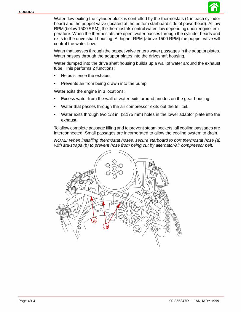
COOLING
Page 4B-4 90-855347R1 JANUARY 1999
Water flow exiting the cylinder block is controlled by the thermostats (1 in each cylinderhead) and the poppet valve (located at the bottom starboard side of powerhead). At lowRPM (below 1500 RPM), the thermostats control water flow depending upon engine tem-perature. When the thermostats are open, water passes through the cylinder heads andexits to the drive shaft housing. At higher RPM (above 1500 RPM) the poppet valve willcontrol the water flow.
Water that passes through the poppet valve enters water passages in the adaptor plates.Water passes through the adaptor plates into the driveshaft housing.
Water dumped into the drive shaft housing builds up a wall of water around the exhausttube. This performs 2 functions:
• Helps silence the exhaust
• Prevents air from being drawn into the pump
Water exits the engine in 3 locations:
• Excess water from the wall of water exits around anodes on the gear housing.
• Water that passes through the air compressor exits out the tell tail.
• Water exits through two 1/8 in. (3.175 mm) holes in the lower adaptor plate into theexhaust.
To allow complete passage filling and to prevent steam pockets, all cooling passages areinterconnected. Small passages are incorporated to allow the cooling system to drain.
NOTE: When installing thermostat hoses, secure starboard to port thermostat hose (a)with sta-straps (b) to prevent hose from being cut by alternator/air compressor belt.
ab

Cylinder Block and Adaptor Plate
Drive Shaft Housing
Lower Unit and Water PumpA
BO
TT
OM
VIE
W
B
B
A
57339
1
2
3
3
4
5
6
7
8
9
10
11
1 - Air Compressor2 - Cylinder Head Cover – Removed from head for illustra-
tion, normally part of head casting3 - Thermostats (2) 143° F (61.6° C) – If stuck closed, engine
will overheat at idle.4 - Strainer Screen for air compressor water supply – If re-
stricted, compressor will overheat and tell-tale will be weak.5 - Exhaust Divider Plate – Separated for illustration6 - Poppet Valve – Controls water flow at high RPM.
Note: If poppet valve is stuck open at low RPM, the engine will not reach proper operating temperature (run cold) and will run rough at idle.
7 - Fuel Cooler – If internal leak occurs, fuel will be forced into cooling system.
8 - Water Outlet from Air Compressor – Connects to tell-tale outlet on bottom cowl.
9 - Water Dump Holes Exhaust Cooling (2 each) 1/8 in. (3.175 mm) – If holes are plugged, tuner pipe will melt and bearing carrier prop shaft seals will be damaged.
10- Water Tube 11- Wall of Water – If water level height is insufficient, water
pump may draw in air resulting in an overheated engine.12- Check Valve for powerhead flush.13- Excess water from wall of water around exhaust bucket exits
around anodes.
12
13
90-855347R1 JANUARY 1999 Page 4B-5
1998/1999 Water Flow Diagram

BO
TT
OM
VIE
W Drive Shaft Housing
Lower Unit and Water Pump
57339
9
10
11
1 - Air Compressor2 - Cylinder Head Cover – Removed from head for illustra-
tion, normally part of head casting3 - Thermostats (2) 143° F (61.6° C) – If stuck closed, engine
will overheat at idle.4 - Strainer Screen for air compressor water supply – If re-
stricted, compressor will overheat and tell-tale will be weak.5 - Exhaust Divider Plate – Separated for illustration6 - Poppet Valve – Controls water flow at high RPM.
Note: If poppet valve is stuck open at low RPM, the engine will not reach proper operating temperature (run cold) and will run rough at idle.
7 - Fuel Cooler – If internal leak occurs, fuel will be forced into cooling system.
8 - Water Outlet from Air Compressor – Connects to fuel cooler and then to tell-tale outlet on bottom cowl.
9 - Water Dump Holes Exhaust Cooling (2 each) 1/8 in. (3.175 mm) – If holes are plugged, tuner pipe will melt and bearing carrier prop shaft seals will be damaged.
10- Water Tube 11- Wall of Water – If water level height is insufficient, water
pump may draw in air resulting in an overheated engine.12- Check Valve for powerhead flush.13- Excess water from wall of water around exhaust bucket exits
around anodes.
13
1
2
3
3
4
5
7
12
Cylinder Block and Adaptor Plate8
6
57389
90-855347R1 JANUARY 1999Page 4B-6
1999 1/2 Water Flow Diagram
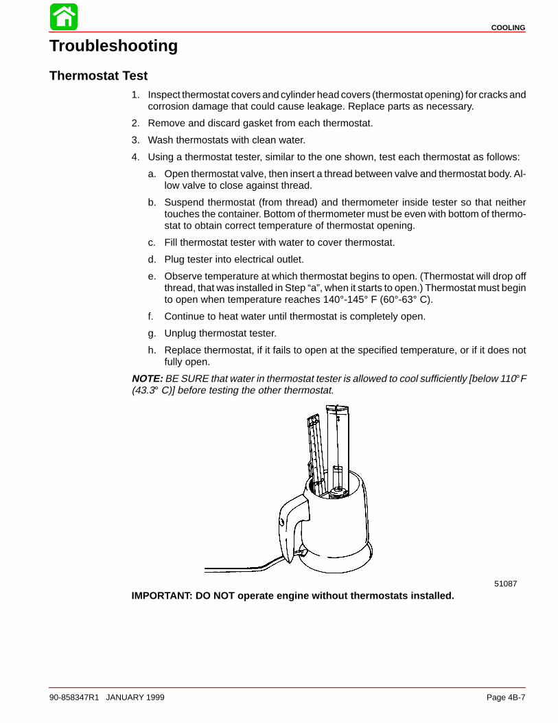
COOLING
90-858347R1 JANUARY 1999 Page 4B-7
Troubleshooting
Thermostat Test1. Inspect thermostat covers and cylinder head covers (thermostat opening) for cracks and
corrosion damage that could cause leakage. Replace parts as necessary.
2. Remove and discard gasket from each thermostat.
3. Wash thermostats with clean water.
4. Using a thermostat tester, similar to the one shown, test each thermostat as follows:
a. Open thermostat valve, then insert a thread between valve and thermostat body. Al-low valve to close against thread.
b. Suspend thermostat (from thread) and thermometer inside tester so that neithertouches the container. Bottom of thermometer must be even with bottom of thermo-stat to obtain correct temperature of thermostat opening.
c. Fill thermostat tester with water to cover thermostat.
d. Plug tester into electrical outlet.
e. Observe temperature at which thermostat begins to open. (Thermostat will drop offthread, that was installed in Step “a”, when it starts to open.) Thermostat must beginto open when temperature reaches 140°-145° F (60°-63° C).
f. Continue to heat water until thermostat is completely open.
g. Unplug thermostat tester.
h. Replace thermostat, if it fails to open at the specified temperature, or if it does notfully open.
NOTE: BE SURE that water in thermostat tester is allowed to cool sufficiently [below 110°F(43.3° C)] before testing the other thermostat.
51087
IMPORTANT: DO NOT operate engine without thermostats installed.
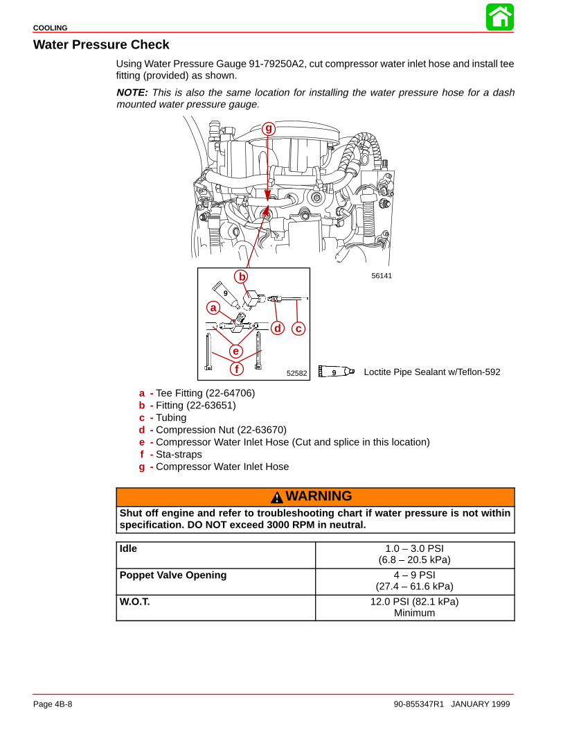
COOLING
Page 4B-8 90-855347R1 JANUARY 1999
Water Pressure CheckUsing Water Pressure Gauge 91-79250A2, cut compressor water inlet hose and install teefitting (provided) as shown.
NOTE: This is also the same location for installing the water pressure hose for a dashmounted water pressure gauge.
52582
9
56141
Loctite Pipe Sealant w/Teflon-5929
g
b
d c
a
e
f
a - Tee Fitting (22-64706)b - Fitting (22-63651)c - Tubingd - Compression Nut (22-63670)e - Compressor Water Inlet Hose (Cut and splice in this location)f - Sta-strapsg - Compressor Water Inlet Hose
WARNINGShut off engine and refer to troubleshooting chart if water pressure is not withinspecification. DO NOT exceed 3000 RPM in neutral.
Idle 1.0 – 3.0 PSI(6.8 – 20.5 kPa)
Poppet Valve Opening 4 – 9 PSI(27.4 – 61.6 kPa)
W.O.T. 12.0 PSI (82.1 kPa)Minimum
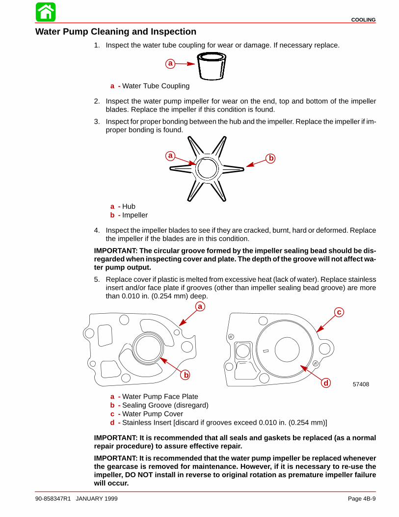
COOLING
90-858347R1 JANUARY 1999 Page 4B-9
Water Pump Cleaning and Inspection1. Inspect the water tube coupling for wear or damage. If necessary replace.
a
a - Water Tube Coupling
2. Inspect the water pump impeller for wear on the end, top and bottom of the impellerblades. Replace the impeller if this condition is found.
3. Inspect for proper bonding between the hub and the impeller. Replace the impeller if im-proper bonding is found.
a b
a - Hubb - Impeller
4. Inspect the impeller blades to see if they are cracked, burnt, hard or deformed. Replacethe impeller if the blades are in this condition.
IMPORTANT: The circular groove formed by the impeller sealing bead should be dis-regarded when inspecting cover and plate. The depth of the groove will not affect wa-ter pump output.
5. Replace cover if plastic is melted from excessive heat (lack of water). Replace stainlessinsert and/or face plate if grooves (other than impeller sealing bead groove) are morethan 0.010 in. (0.254 mm) deep.
57408
a
b
c
d
a - Water Pump Face Plateb - Sealing Groove (disregard)c - Water Pump Coverd - Stainless Insert [discard if grooves exceed 0.010 in. (0.254 mm)]
IMPORTANT: It is recommended that all seals and gaskets be replaced (as a normalrepair procedure) to assure effective repair.
IMPORTANT: It is recommended that the water pump impeller be replaced wheneverthe gearcase is removed for maintenance. However, if it is necessary to re-use theimpeller, DO NOT install in reverse to original rotation as premature impeller failurewill occur.

COOLING
Page 4B-10 90-855347R1 JANUARY 1999
Problem Diagnosis
Condition Recommended Range Possible Cause
Pressure below specification @idle
1.0 – 3.0 PSI (6.8 – 20.5 kPa) •Poppet valve spring defective(weak, broken, missing)•Defective poppet valve seal•Thermostat stuck open•Severe internal leak•Low output water pump• Inlet restriction•Strainer screen for air compres-sor water supply is restricted
Pressure above 5 psi (34.2kPa)@ idle
1.0 – 3.0 PSI (6.8 – 20.5 kPa) •Plugged poppet by-pass pas-sage or fuel cooler
Pressure does not drop between1000 – 2500 RPM indicating pop-pet valve has opened
4 – 9 PSI (27.4 – 61.6 kPa) be-tween 1000 – 2200 RPM
•Wrong poppet valve spring•Low output water pump• Inlet restriction•Poppet valve vent hole pluggedor restricted•Severe internal leak•Defective poppet valve seal
Poppet valve flutter/water pres-sure drop does not stabilize priorto 2500 RPM
4 – 9 PSI (27.4 – 61.6 kPa) be-tween 1000 – 2200 RPM
•Wrong poppet valve spring•Low output water pump• Inlet restriction•Broken diaphragm in poppetvalve•Severe internal leak•Defective poppet valve seal
Pressure is below minimum spec-ification @ W.O.T.
12 PSI (54.9 – 68.5kPa) • Inlet restriction•Engine mounted too high ontransom•Engine trimmed out too far•Configuration of boat bottom in-terfering with adequate flow ofwater to coolant inlets•Severe internal leak•Low output water pump•Plugged strainer screen for aircompressor water supply
Pressure higher than normal @W.O.T., but engine still indicatesoverheat condition
Maximum pressure – 23 PSI(157.4 kPa)
•Outlet water passages restricted.•Steam pocket has formed at topof powerhead due to lack of cool-ing water
5A
CLAMP/SWIVEL BRACKETS & DRIVE SHAFT HOUSING
90-855347R1 JANUARY 1999 Page 5A-1
MID-SECTIONSection 5A – Clamp/Swivel Brackets & Drive Shaft Housing
Table of Contents
Swivel Bracket and Steering Arm 5A-2. . . . . . . . . . . . Transom Brackets 5A-4. . . . . . . . . . . . . . . . . . . . . . . . . Drive Shaft Housing and Exhaust Tube 5A-6. . . . . . Drive Shaft Housing and Dyna-Float Suspension 5A-8. . . . . . . . . . . . . . . . . . . . . . . . . . . . . .
Removal and Disassembly 5A-8. . . . . . . . . . . . . . Reassembly and Installation 5A-11. . . . . . . . . . . .

CLAMP/SWIVEL BRACKETS & DRIVE SHAFT HOUSING
Page 5A-2 90-855347R1 JANUARY 1999
Swivel Bracket and Steering Arm
12 3
4
5
6
7
8
9
1011
1213
1415
16
17
18
19
20
21
22
23
2425
26
3
27
29
28
30
95
95
95
7
95
95
95
B
7 Loctite “271” Adhesive Sealant (92-809819)
95 2-4-C w/Teflon (92-825407A12)
A
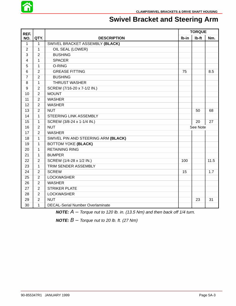
CLAMP/SWIVEL BRACKETS & DRIVE SHAFT HOUSING
90-855347R1 JANUARY 1999 Page 5A-3
Swivel Bracket and Steering Arm
REF. TORQUEREF.NO. QTY. DESCRIPTION lb-in lb-ft Nm.
1 1 SWIVEL BRACKET ASSEMBLY (BLACK)2 1 OIL SEAL (LOWER)3 2 BUSHING4 1 SPACER5 1 O-RING6 2 GREASE FITTING 75 8.57 2 BUSHING
8 1 THRUST WASHER9 2 SCREW (7/16-20 x 7-1/2 IN.)10 2 MOUNT11 2 WASHER12 2 WASHER13 2 NUT 50 6814 1 STEERING LINK ASSEMBLY
15 1 SCREW (3/8-24 x 1-1/4 IN.) 20 2716 2 NUT See Note17 2 WASHER18 1 SWIVEL PIN AND STEERING ARM (BLACK)19 1 BOTTOM YOKE (BLACK)20 1 RETAINING RING21 1 BUMPER
22 2 SCREW (1/4-28 x 1/2 IN.) 100 11.523 1 TRIM SENDER ASSEMBLY24 2 SCREW 15 1.725 2 LOCKWASHER26 2 WASHER27 2 STRIKER PLATE28 2 LOCKWASHER
29 2 NUT 23 3130 1 DECAL-Serial Number Overlaminate
NOTE: A – Torque nut to 120 lb. in. (13.5 Nm) and then back off 1/4 turn.
NOTE: B – Torque nut to 20 lb. ft. (27 Nm)
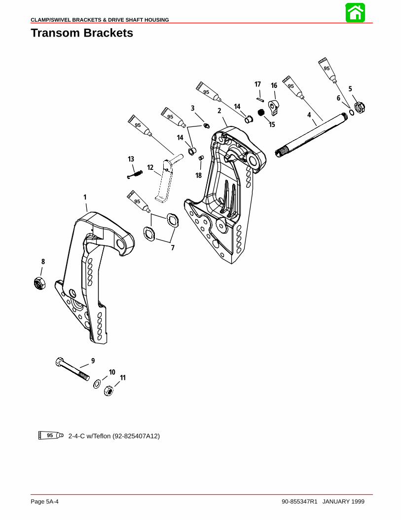
CLAMP/SWIVEL BRACKETS & DRIVE SHAFT HOUSING
Page 5A-4 90-855347R1 JANUARY 1999
Transom Brackets
1
234
56
7
8
9
1011
1213
15
1617
18
14
14
95
9595
95
95
95
95 2-4-C w/Teflon (92-825407A12)

CLAMP/SWIVEL BRACKETS & DRIVE SHAFT HOUSING
90-855347R1 JANUARY 1999 Page 5A-5
Transom Brackets
REF. TORQUEREF.NO. QTY. DESCRIPTION lb-in lb-ft Nm.
1 1 TRANSOM BRACKET (STARBOARD)(BLACK)2 1 TRANSOM BRACKET (PORT) (BLACK)3 1 GREASE FITTING (PORT) 80 94 1 TILT TUBE5 1 NUT (1 IN.-14) 45 616 1 O-RING7 2 WAVE WASHER
8 1 NUT (7/8-14) 45 619 4 BOLT10 4 WASHER11 4 NUT12 1 TILT LOCK LEVER ASSEMBLY13 1 SPRING14 2 BUSHING
15 1 SPRING16 1 KNOB17 1 GROOVE PIN18 1 PIN
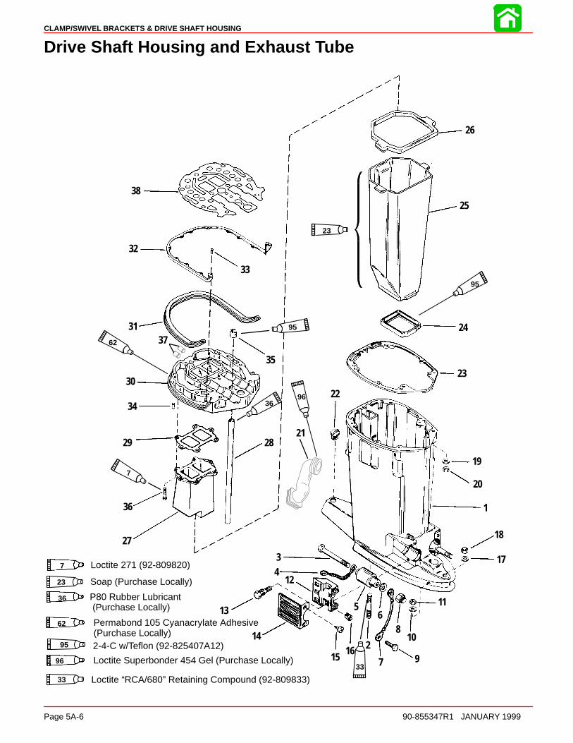
CLAMP/SWIVEL BRACKETS & DRIVE SHAFT HOUSING
Page 5A-6 90-855347R1 JANUARY 1999
Drive Shaft Housing and Exhaust Tube
1
2
34
56
7
8
9
10
11
12
13
14
1516
17
18
19
20
21
22
23
24
25
26
27
2829
30
31
32
33
34
35
36
38
P80 Rubber Lubricant(Purchase Locally)
23
7
96
36
Loctite Superbonder 454 Gel (Purchase Locally)9633
95
95
36
62
Permabond 105 Cyanacrylate Adhesive(Purchase Locally)
62
37
Soap (Purchase Locally)23
Loctite “RCA/680” Retaining Compound (92-809833)33
95 2-4-C w/Teflon (92-825407A12)
7 Loctite 271 (92-809820)

CLAMP/SWIVEL BRACKETS & DRIVE SHAFT HOUSING
90-855347R1 JANUARY 1999 Page 5A-7
Drive Shaft Housing and Exhaust Tube
REF. TORQUEREF.NO. QTY. DESCRIPTION lb-in lb-ft Nm.
11 DRIVE SHAFT HOUSING (LONG)(BLACK)
11 DRIVE SHAFT HOUSING (X-LONG)(BLACK)
2 2 STUD3 2 SCREW (1/2-20 x 6 IN.)4 1 GROUND WIRE5 2 LOWER MOUNT6 2 WASHER
7 1 GROUND WIRE8 2 NUT 50 689 1 SCREW (1/4-20 x 3/8 IN.)10 2 WASHER11 2 NUT 50 6812 2 CLAMP13 4 SCREW (5/16-18 x 1-1/4 IN.) 22 30
14 2 COVER (BLACK)15 4 SCREW (12-24 x 5/8 IN.) 17 1.916 4 NUT 25 3417 1 WASHER18 1 NUT 57 7719 4 WASHER20 4 NUT 23 31
21 1 IDLE EXHAUST BOOT22 1 PLUG23 1 GASKET24 1 SEAL (LOWER)25 1 EXHAUST TUBE26 1 SEAL (UPPER)
271 EXHAUST EXTENSION (150)
271 EXHAUST EXTENSION (135)
281 WATER TUBE (LONG)
281 WATER TUBE (X-LONG)
29 1 GASKET30 1 PLATE ASSEMBLY31 1 SEAL32 1 BRACKET
33 12 SCREW (10-16 x 1/2 IN.) 80 934 2 DOWEL PIN35 1 SEAL36 6 SCREW (1/4-20 x 3/4 IN.) 60 737 2 PLUG (USE WHERE APPLICABLE)38 1 GASKET
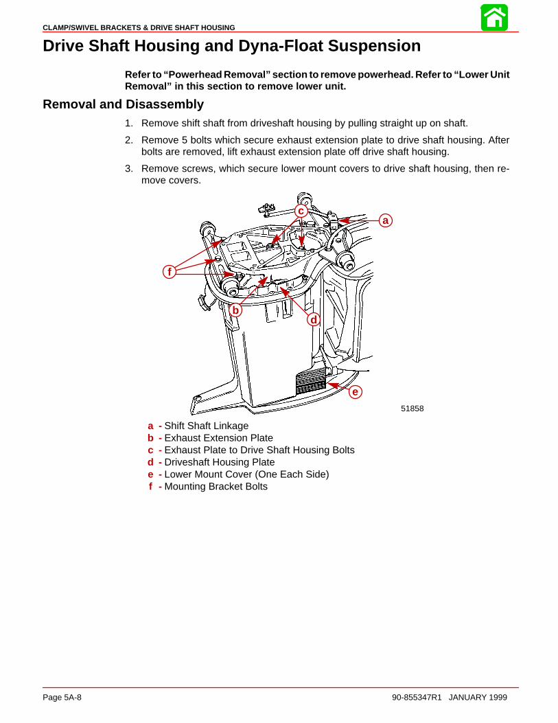
CLAMP/SWIVEL BRACKETS & DRIVE SHAFT HOUSING
Page 5A-8 90-855347R1 JANUARY 1999
Drive Shaft Housing and Dyna-Float Suspension
Refer to “Powerhead Removal” section to remove powerhead. Refer to “Lower UnitRemoval” in this section to remove lower unit.
Removal and Disassembly1. Remove shift shaft from driveshaft housing by pulling straight up on shaft.
2. Remove 5 bolts which secure exhaust extension plate to drive shaft housing. Afterbolts are removed, lift exhaust extension plate off drive shaft housing.
3. Remove screws, which secure lower mount covers to drive shaft housing, then re-move covers.
51858
a
b
c
d
e
f
a - Shift Shaft Linkageb - Exhaust Extension Platec - Exhaust Plate to Drive Shaft Housing Boltsd - Driveshaft Housing Platee - Lower Mount Cover (One Each Side)f - Mounting Bracket Bolts

CLAMP/SWIVEL BRACKETS & DRIVE SHAFT HOUSING
90-855347R1 JANUARY 1999 Page 5A-9
SHIFT LINKAGE ASSEMBLY
a b
c
dd
e
f
g
a - Shift Shaft Assemblyb - Bushingc - Lock Nutd - Washer (2)e - Bushing (Hidden)f - Springg - Guide Block
1. Remove upper mount nuts and flat washers.
aa
a - Upper Mount Nuts
2. Lift driveshaft housing plate off housing.a
b 51850
a
ba - Drive Shaft Housing Plateb - Drive Shaft Housing

CLAMP/SWIVEL BRACKETS & DRIVE SHAFT HOUSING
Page 5A-10 90-855347R1 JANUARY 1999
3. Remove water tube from driveshaft housing plate.
4. Exhaust diffuser is secured to housing plate with 6 bolts. Remove bolts, then removediffuser.
5. Pull exhaust tube out of drive shaft housing.
51850
51857
c
d
a
b
a - Water Tubeb - Exhaust Diffuserc - Exhaust Tubed - Drive Shaft Housing
6. Remove all gasket material from driveshaft housing and related components.
7. Remove bolts, which secure lower mount retainers to drive shaft housing, and removeretainers.
8. Remove rubber caps from lower mount bolts.
51855
a
b
a - Boltsb - Lower Mount Retainer (One Each Side)

CLAMP/SWIVEL BRACKETS & DRIVE SHAFT HOUSING
90-855347R1 JANUARY 1999 Page 5A-11
9. Remove lower mount nuts.
51855
a
b
a - Lower Mount Nutsb - Lower Mount
10. Remove driveshaft housing from swivel bracket by pulling alternately from top to bot-tom on housing.
11. Remove upper and lower mounts by lifting them out of driveshaft housing.
Reassembly and Installation1. Apply a thin coat of 2-4-C w/Teflon Marine Lubricant onto inside portion of exhaust
tube seal.
2. Install exhaust tube seal into driveshaft housing with tapered side of seal facing up.
51856
a
b
a - Exhaust Tube Sealb - Driveshaft Housing

CLAMP/SWIVEL BRACKETS & DRIVE SHAFT HOUSING
Page 5A-12 90-855347R1 JANUARY 1999
3. Push exhaust tube boots onto tabs on each side of exhaust tube.
4. Position exhaust tube in drive shaft housing and push down on tube until boots restin grooves on inside of housing.
5. Position driveshaft housing to plate gasket on top of housing.
6. Install an exhaust diffuser gasket and exhaust diffuser onto plate, then secure bothto plate with 6 bolts. Clean bolts with Loctite 7649 Primer and then apply Loctite 271to bolt threads. Torque bolts to 60 Ib. in. (7.0 Nm).
51857
c
d
51856
a
b b
a - Exhaust Tubeb - Exhaust Tube Bootsc - Exhaust Diffuser Gasketd - Exhaust Diffuser
7. Apply a small amount of 2-4-C w/Teflon Marine Lubricant onto water tube seal.
8. Install water tube seal into driveshaft housing plate with plastic end of seal facing upand install water tube.
51856
a
b
a - Water Tube Sealb - Driveshaft Housing Plate
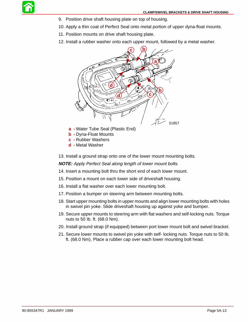
CLAMP/SWIVEL BRACKETS & DRIVE SHAFT HOUSING
90-855347R1 JANUARY 1999 Page 5A-13
9. Position drive shaft housing plate on top of housing.
10. Apply a thin coat of Perfect Seal onto metal portion of upper dyna-float mounts.
11. Position mounts on drive shaft housing plate.
12. Install a rubber washer onto each upper mount, followed by a metal washer.
51857
a
bcd
d
bc
a - Water Tube Seal (Plastic End)b - Dyna-Float Mountsc - Rubber Washersd - Metal Washer
13. Install a ground strap onto one of the lower mount mounting bolts.
NOTE: Apply Perfect Seal along length of lower mount bolts.
14. Insert a mounting bolt thru the short end of each lower mount.
15. Position a mount on each lower side of driveshaft housing.
16. Install a flat washer over each lower mounting bolt.
17. Position a bumper on steering arm between mounting bolts.
18. Start upper mounting bolts in upper mounts and align lower mounting bolts with holesin swivel pin yoke. Slide driveshaft housing up against yoke and bumper.
19. Secure upper mounts to steering arm with flat washers and self-locking nuts. Torquenuts to 50 Ib. ft. (68.0 Nm).
20. Install ground strap (if equipped) between port lower mount bolt and swivel bracket.
21. Secure lower mounts to swivel pin yoke with self- locking nuts. Torque nuts to 50 Ib.ft. (68.0 Nm). Place a rubber cap over each lower mounting bolt head.

CLAMP/SWIVEL BRACKETS & DRIVE SHAFT HOUSING
Page 5A-14 90-855347R1 JANUARY 1999
22. Install lower mount retainers and secure each retainer with 2 bolts. (Secure groundstrap with the nearest retainer bolt.) Torque bolts to 160 Ib. in. (18.0 Nm).
5185551855
e
f
f
g
a
b
d
c
a - Lower Mountb - Nut [Torque to 50 lb. ft. (68.0 Nm)]c - Rubber Capd - Ground Strap (only one side)e - Lower Mount Retainerf - Bolts [Torque to 160 lb. in. (18.0 Nm)]g - Ground Strap
23. Install lower mount covers and secure each cover with 2 screws.
24. Install exhaust extension plate on driveshaft housing with shift shaft assembly. Secureextension plate to drive shaft housing with 5 bolts.
51858
c
d
e
f
g
h
51855
a
b
a - Cover (One Each Side)b - Screws (Two for Each Cover)c - Shift Shaft Linkaged - Exhaust Extension Platee - Exhaust Plate to Driveshaft Housing Bolts, Torque to 25 Ib. ft. (34 Nm)f - Drive Shaft Housing Plateg - Lower Mount Cover (One Each Side)h - Mounting Bracket Bolts, Torque to 40 Ib. ft. (54 Nm)
5B
POWER TRIM
90-855347R1 JANUARY 1999 Page 5B-1
MID-SECTIONSection 5B – Power Trim
Table of Contents
Power Trim Specifications 5B-1. . . . . . . . . . . . . . . . . . . . . Special Tools 5B-2. . . . . . . . . . . . . . . . . . . . . . . . . . . . . . . . Power Trim Components 5B-4. . . . . . . . . . . . . . . . . . . . . . Power Trim Motor 5B-6. . . . . . . . . . . . . . . . . . . . . . . . . . . . Power Trim - General Information 5B-7. . . . . . . . . . . . . .
Description 5B-7. . . . . . . . . . . . . . . . . . . . . . . . . . . . . . . Trimming Characteristics 5B-7. . . . . . . . . . . . . . . . . . . Trailering Outboard 5B-8. . . . . . . . . . . . . . . . . . . . . . . . Tilting Outboard Manually 5B-8. . . . . . . . . . . . . . . . . . Trim “In” Angle Adjustment 5B-9. . . . . . . . . . . . . . . . . Striker Plate Replacement 5B-9. . . . . . . . . . . . . . . . . . Anode Plate 5B-10. . . . . . . . . . . . . . . . . . . . . . . . . . . . . Trim Indicator Gauge 5B-10. . . . . . . . . . . . . . . . . . . . . Check, Fill and Purge - Power Trim System 5B-10. . Troubleshooting 5B-12. . . . . . . . . . . . . . . . . . . . . . . . . . Power Trim System with Relays and 2 WireTrim Motor 5B-14. . . . . . . . . . . . . . . . . . . . . . . . . . . . . .
Electrical System Troubleshooting 5B-15. . . . . . . . . . . . . General Checks 5B-15. . . . . . . . . . . . . . . . . . . . . . . . . .
Troubleshooting the “Down Circuit” 5B-15. . . . . . . . . . . . Troubleshooting the “Up” Circuit 5B-16. . . . . . . . . . . . . . . Troubleshooting the “Down” and “Up” Circuits(All Circuits Inoperative) 5B-17. . . . . . . . . . . . . . . . . . . . . . Power Trim Assembly Removal and Installation 5B-18.
Removal 5B-18. . . . . . . . . . . . . . . . . . . . . . . . . . . . . . . .
Installation 5B-21. . . . . . . . . . . . . . . . . . . . . . . . . . . . . . . Testing Power Trim System With TestGauge Kit (91-52915A6) 5B-23. . . . . . . . . . . . . . . . . . “UP” Pressure Check 5B-23. . . . . . . . . . . . . . . . . . . . . “DOWN” Pressure Check 5B-26. . . . . . . . . . . . . . . . . . Hydraulic Repair 5B-28. . . . . . . . . . . . . . . . . . . . . . . . . Trim Rod End Cap Seal 5B-29. . . . . . . . . . . . . . . . . . . Tilt Ram 5B-30. . . . . . . . . . . . . . . . . . . . . . . . . . . . . . . . . Disassembly 5B-31. . . . . . . . . . . . . . . . . . . . . . . . . . . . . Scraper Seal Replacement 5B-34. . . . . . . . . . . . . . . .
Motor and Electrical Tests/Repair 5B-38. . . . . . . . . . . . . . Trim Pump Motor Test 5B-38. . . . . . . . . . . . . . . . . . . . Motor Disassembly 5B-38. . . . . . . . . . . . . . . . . . . . . . . Armature Tests 5B-39. . . . . . . . . . . . . . . . . . . . . . . . . . . Motor Repair 5B-40. . . . . . . . . . . . . . . . . . . . . . . . . . . . . Reassembly 5B-44. . . . . . . . . . . . . . . . . . . . . . . . . . . . . Reassembly - Motor and Pump 5B-46. . . . . . . . . . . . Priming Power Trim System 5B-47. . . . . . . . . . . . . . . Trim Sender Test 5B-47. . . . . . . . . . . . . . . . . . . . . . . . . Trim Indicator Gauge Needle Adjustment 5B-48. . . .
Trim Indicator Wiring Diagrams 5B-49. . . . . . . . . . . . . . .
Power Trim Specifications
NOTE: Maximum acceptable amount of leak down in 24 hours is 2 inches (50.8 mm).
Test Reading
Trim “UP” 1300 PSI (91kg/cm2)Maximum Pressure
Trim “DOWN” 500 PSI (35kg/cm2)Minimum Pressure
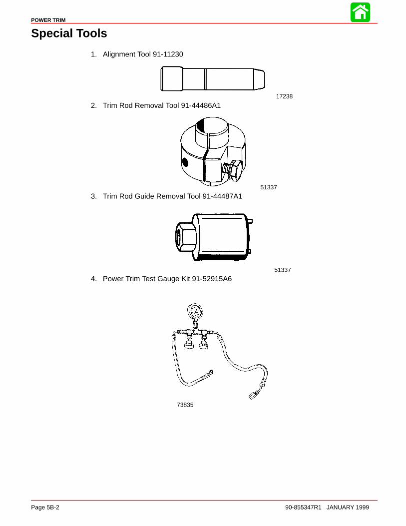
POWER TRIM
Page 5B-2 90-855347R1 JANUARY 1999
Special Tools
1. Alignment Tool 91-11230
17238
2. Trim Rod Removal Tool 91-44486A1
51337
3. Trim Rod Guide Removal Tool 91-44487A1
51337
4. Power Trim Test Gauge Kit 91-52915A6
73835
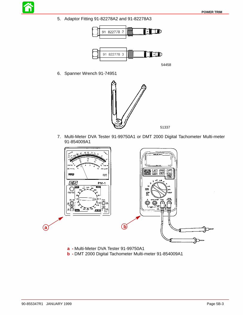
POWER TRIM
90-855347R1 JANUARY 1999 Page 5B-3
5. Adaptor Fitting 91-82278A2 and 91-82278A3
54458
6. Spanner Wrench 91-74951
51337
7. Multi-Meter DVA Tester 91-99750A1 or DMT 2000 Digital Tachometer Multi-meter91-854009A1
a b
a - Multi-Meter DVA Tester 91-99750A1b - DMT 2000 Digital Tachometer Multi-meter 91-854009A1
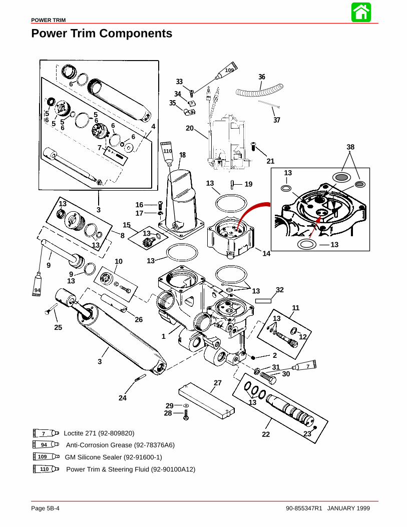
POWER TRIM
Page 5B-4 90-855347R1 JANUARY 1999
Power Trim Components
1
2
3
4
5
6
7
8
9 10
11
12
13
14
15
1617
19
20
21
22 23
24
2526
27
2829
3031
32
55
66
66 5
13
13
13
13
13
13
13
9
3
6
18
33
3435
94
7
109
94 Anti-Corrosion Grease (92-78376A6)
109 GM Silicone Sealer (92-91600-1)
36
37
1313
13
7 Loctite 271 (92-809820)
Power Trim & Steering Fluid (92-90100A12)
11038
110

POWER TRIM
90-855347R1 JANUARY 1999 Page 5B-5
Power Trim Components
REF. TORQUEREF.NO. QTY. DESCRIPTION lb-in lb-ft Nm.
– 1 POWER TRIM ASSEMBLY–Complete
1 1 MANIFOLD ASSEMBLY2 9 PIPE PLUG3 1 TILT CYLINDER ASSEMBLY4 1 PISTON ROD5 1 GUIDE KIT6 1 REPAIR KIT
7 1 CHECK VALVE KIT8 2 GUIDE ASSEMBLY
91 PISTON/ROD ASSEMBLY (PORT)
91 PISTON/ROD ASSEMBLY (STBD.)
10 1 TRIM FILTER ASSEMBLY11 1 VALVE ASSEMBLY12 1 E RING
13 1 O RING KIT14 1 PUMP15 1 PLUG ASSEMBLY16 4 SCREW17 4 WASHER18 1 COVER19 1 DRIVE SHAFT
20 1 TRIM MOTOR(Breakdown on Power Trim Motor)
212 SCREW (LONG) 80 9
212 SCREW (SHORT) 80 9
22 1 SHAFT ASSEMBLY
23 2 PIPE PLUG24 1 GROOVE PIN25 1 GROOVE PIN26 1 SHAFT27 1 ANODE ASSEMBLY28 2 SCREW (M6 x 1 x 25) 70 829 2 WASHER
30 6 SCREW (M10 x 1.5 x 30) 45 6131 6 WASHER32 1 DECAL-Caution power trim33 1 SCREW (10-16 x 3/5 IN.)34 1 C WASHER35 2 CLAMP36 1 TUBING
37 1 STA-STRAP38 2 FILTER SCREENS
NOTE: Lubricate all O-rings with Power Trim and Steering Fluid.
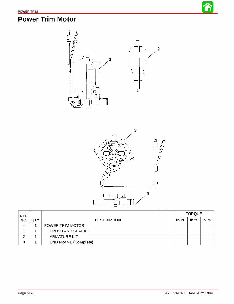
POWER TRIM
Page 5B-6 90-855347R1 JANUARY 1999
Power Trim Motor
1
2
3
3
REF. TORQUEREF.NO. QTY. DESCRIPTION lb.in. lb.ft. N·m
– 1 POWER TRIM MOTOR
1 1 BRUSH AND SEAL KIT2 1 ARMATURE KIT3 1 END FRAME (Complete)
POWER TRIM
90-855347R1 JANUARY 1999 Page 5B-7
Power Trim - General Information
DescriptionThe Power Trim System consists of an electric motor, pressurized fluid reservoir, pump,tilt cylinder, and two trim rams.
The remote control (or trim panel) has switches that trim the outboard “Up” or “Down” andtilt the engine for “Trailering”. The outboard can be trimmed and tilted under power orwhen the outboard is not running.
Trimming CharacteristicsNOTE: Because hull designs react differently in varying water conditions, varying the trimposition will often improve the ride and boat handling. When trimming from a mid-trimposition (with outboard trim tab in a straight fore and aft position), expect the following:
TRIMMING OUTBOARD “UP” (OUT):
WARNINGExcessive trim “Out” may reduce the stability of some high speed hulls. To cor-rect instability, reduce the power gradually and trim the outboard “In” slightly be-fore resuming high speed operation. A rapid reduction in power will result in asudden change of steering torque and may cause additional boat instability.
Will lift boat bow, increasing top speed.
Transfers steering torque harder to port (left) on installations below 23 in. (584.2 mm) tran-som height.
Increases gearcase clearance over submerged objects.
Excess trim can cause “porpoising” and/or ventilation.
WARNINGExcessive outboard trim angle will result in insufficient water supply causingwater pump and/or powerhead overheating damage. Insure water level is abovewater intake holes whenever outboard is running.
The “Up” circuit actuates the up solenoid (under outboard cowl) and closes the motor cir-cuit. The electric motor drives the pump, forcing fluid thru passageways into the up sideof the trim cylinders.
The trim cylinders position the outboard at the desired trim angle in the 20 degree maxi-mum trim range. The system will not allow the outboard to be trimmed above the 20 de-gree trim range as long as the engine RPM is above approximately 2000 RPM.
The outboard can be trimmed above the 20 degree maximum trim angle (for shallow wa-ter operation, etc.), by keeping the engine RPM below 2000. If the RPM increases over2000, propeller thrust (if propeller is deep enough) will cause the trim system to return theoutboard to the 20 degree maximum trim position.
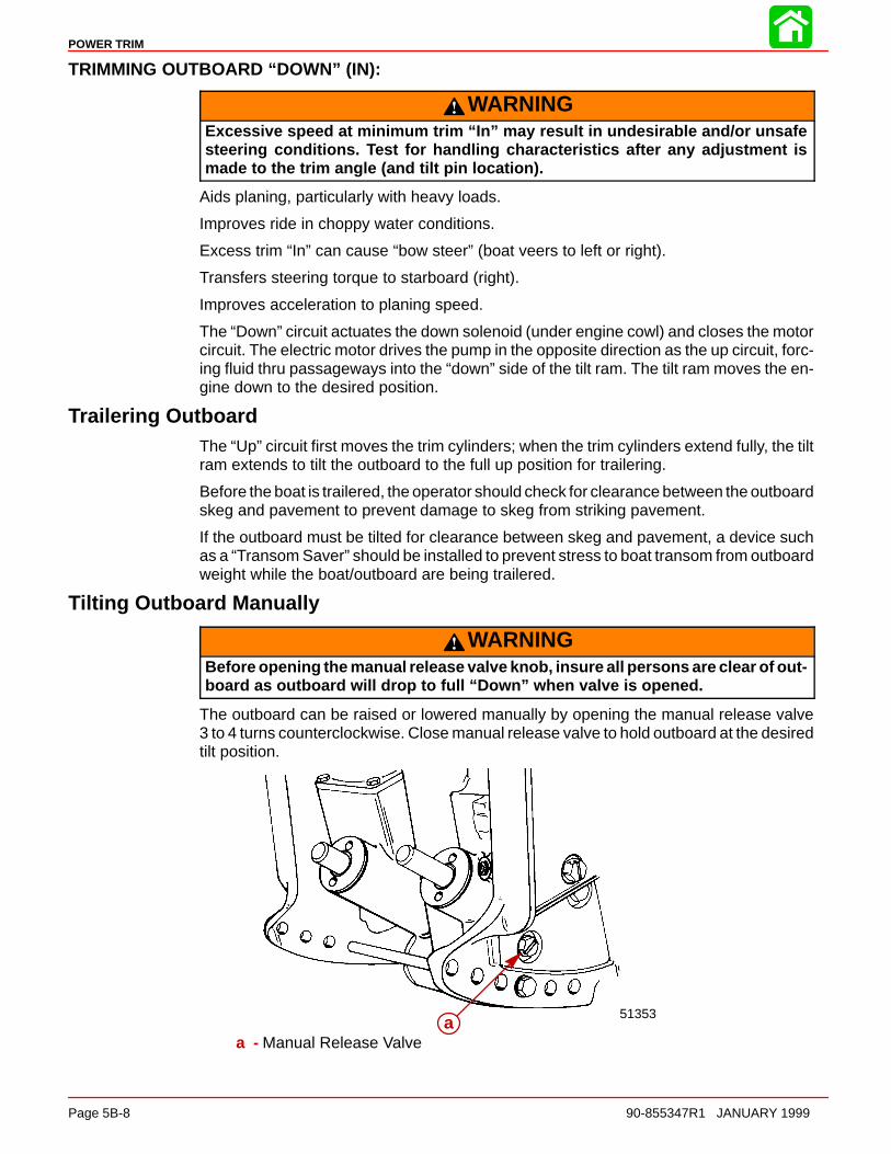
POWER TRIM
Page 5B-8 90-855347R1 JANUARY 1999
TRIMMING OUTBOARD “DOWN” (IN):
WARNINGExcessive speed at minimum trim “In” may result in undesirable and/or unsafesteering conditions. Test for handling characteristics after any adjustment ismade to the trim angle (and tilt pin location).
Aids planing, particularly with heavy loads.
Improves ride in choppy water conditions.
Excess trim “In” can cause “bow steer” (boat veers to left or right).
Transfers steering torque to starboard (right).
Improves acceleration to planing speed.
The “Down” circuit actuates the down solenoid (under engine cowl) and closes the motorcircuit. The electric motor drives the pump in the opposite direction as the up circuit, forc-ing fluid thru passageways into the “down” side of the tilt ram. The tilt ram moves the en-gine down to the desired position.
Trailering OutboardThe “Up” circuit first moves the trim cylinders; when the trim cylinders extend fully, the tiltram extends to tilt the outboard to the full up position for trailering.
Before the boat is trailered, the operator should check for clearance between the outboardskeg and pavement to prevent damage to skeg from striking pavement.
If the outboard must be tilted for clearance between skeg and pavement, a device suchas a “Transom Saver” should be installed to prevent stress to boat transom from outboardweight while the boat/outboard are being trailered.
Tilting Outboard Manually
WARNINGBefore opening the manual release valve knob, insure all persons are clear of out-board as outboard will drop to full “Down” when valve is opened.
The outboard can be raised or lowered manually by opening the manual release valve3 to 4 turns counterclockwise. Close manual release valve to hold outboard at the desiredtilt position.
51353aa
a - Manual Release Valve
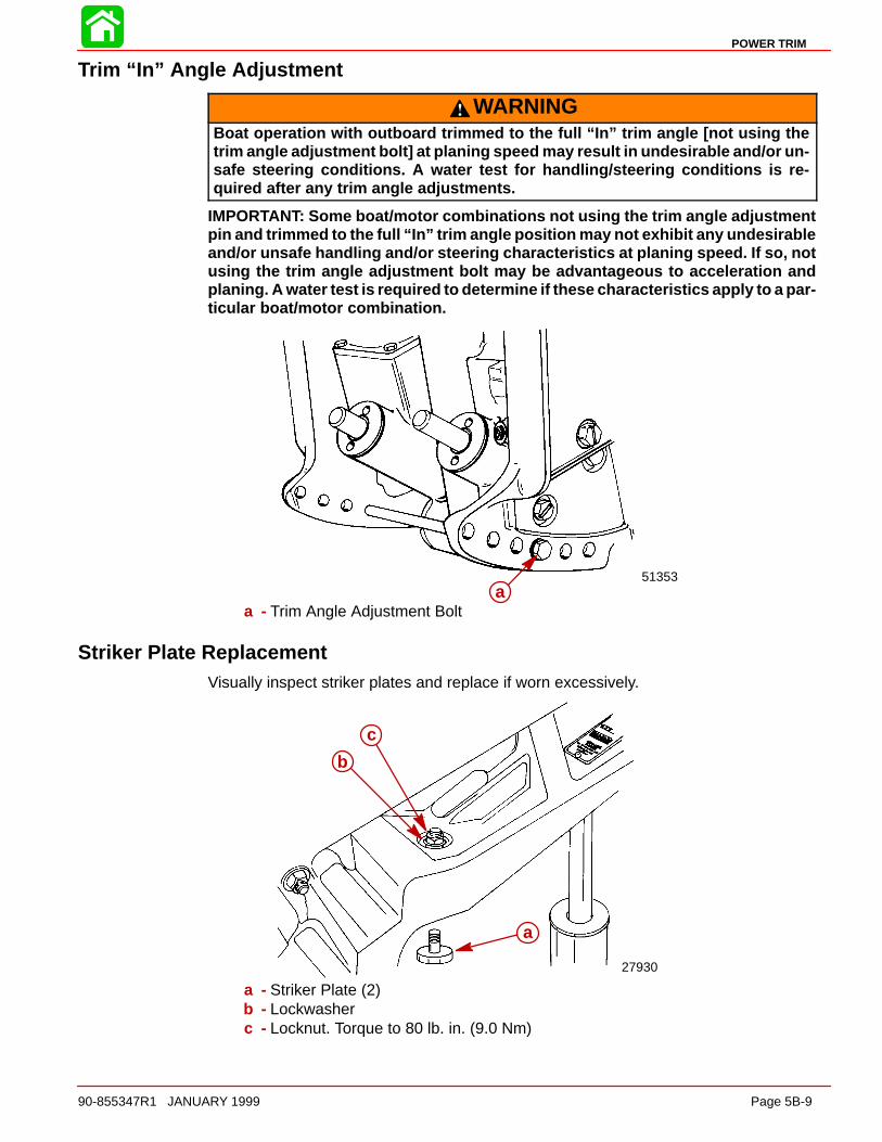
POWER TRIM
90-855347R1 JANUARY 1999 Page 5B-9
Trim “In” Angle Adjustment
WARNINGBoat operation with outboard trimmed to the full “In” trim angle [not using thetrim angle adjustment bolt] at planing speed may result in undesirable and/or un-safe steering conditions. A water test for handling/steering conditions is re-quired after any trim angle adjustments.
IMPORTANT: Some boat/motor combinations not using the trim angle adjustmentpin and trimmed to the full “In” trim angle position may not exhibit any undesirableand/or unsafe handling and/or steering characteristics at planing speed. If so, notusing the trim angle adjustment bolt may be advantageous to acceleration andplaning. A water test is required to determine if these characteristics apply to a par-ticular boat/motor combination.
51353a
a - Trim Angle Adjustment Bolt
Striker Plate ReplacementVisually inspect striker plates and replace if worn excessively.
27930
a
b
c
a - Striker Plate (2)b - Lockwasherc - Locknut. Torque to 80 lb. in. (9.0 Nm)
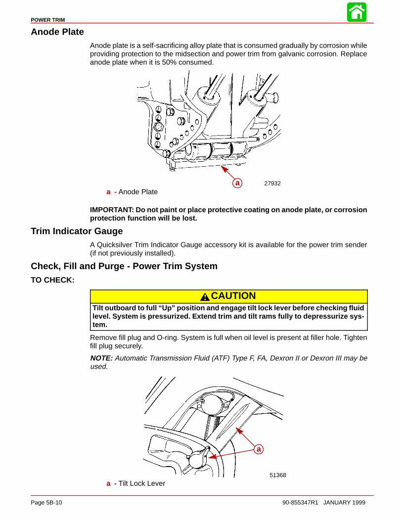
POWER TRIM
Page 5B-10 90-855347R1 JANUARY 1999
Anode PlateAnode plate is a self-sacrificing alloy plate that is consumed gradually by corrosion whileproviding protection to the midsection and power trim from galvanic corrosion. Replaceanode plate when it is 50% consumed.
27932aa - Anode Plate
IMPORTANT: Do not paint or place protective coating on anode plate, or corrosionprotection function will be lost.
Trim Indicator GaugeA Quicksilver Trim Indicator Gauge accessory kit is available for the power trim sender(if not previously installed).
Check, Fill and Purge - Power Trim SystemTO CHECK:
CAUTIONTilt outboard to full “Up” position and engage tilt lock lever before checking fluidlevel. System is pressurized. Extend trim and tilt rams fully to depressurize sys-tem.
Remove fill plug and O-ring. System is full when oil level is present at filler hole. Tightenfill plug securely.
NOTE: Automatic Transmission Fluid (ATF) Type F, FA, Dexron II or Dexron III may beused.
51368
a
a - Tilt Lock Lever
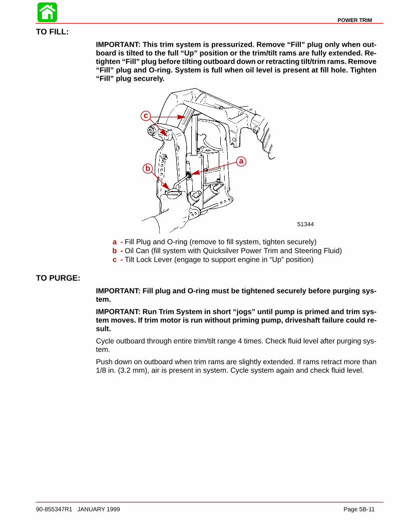
POWER TRIM
90-855347R1 JANUARY 1999 Page 5B-11
TO FILL:
IMPORTANT: This trim system is pressurized. Remove “Fill” plug only when out-board is tilted to the full “Up” position or the trim/tilt rams are fully extended. Re-tighten “Fill” plug before tilting outboard down or retracting tilt/trim rams. Remove“Fill” plug and O-ring. System is full when oil level is present at fill hole. Tighten“Fill” plug securely.
51344
ab
c
a - Fill Plug and O-ring (remove to fill system, tighten securely)b - Oil Can (fill system with Quicksilver Power Trim and Steering Fluid)c - Tilt Lock Lever (engage to support engine in “Up” position)
TO PURGE:
IMPORTANT: Fill plug and O-ring must be tightened securely before purging sys-tem.
IMPORTANT: Run Trim System in short “jogs” until pump is primed and trim sys-tem moves. If trim motor is run without priming pump, driveshaft failure could re-sult.
Cycle outboard through entire trim/tilt range 4 times. Check fluid level after purging sys-tem.
Push down on outboard when trim rams are slightly extended. If rams retract more than1/8 in. (3.2 mm), air is present in system. Cycle system again and check fluid level.

51491
1
2
3
4
56
7
10
POWER TRIM
Page 5B-12 90-855347R1 JANUARY 1999
TroubleshootingIMPORTANT: Determine if Electrical or Hydraulic problem exists.
IMPORTANT: Acceptable power trim leak down should not exceed 1 in. (25.4 mm)(when measured at the tilt ram) in a 24 hour period.
HYDRAULIC SYSTEM TROUBLESHOOTING
IMPORTANT: Make one correction at a time. Check operation of trim system beforeproceeding to the next check.
CONDITION OF TRIM SYSTEM PROBLEM
A. Trim motor runs; trim system does not move up or down. 1, 2, 5, 10
B. Does not trim full down. Up trim OK. 2, 3, 4
C. Does not trim full up. Down trim OK. 1, 6
D. Partial or “Jerky” down/up. 1, 3
E. “Thump” noise when shifting. 2, 3, 6, 7
F. Does not trim under load. 5, 8, 9,10
G. Does not hold trim position under load. 2, 5, 6
H. Trail out when backing off from high speed. 3, 4
I. Leaks down and does not hold trim. 2, 5, 7
J. Trim motor working hard and trims slow up and down. 8, 9
K. Trims up very slow. 1, 2, 8, 9
L. Starts to trim up from full down position when “IN” trim button is depressed. 3, 4
M. Trim position will not hold in reverse. 3, 4
PROBLEM1. Low oil level.
2. Pump assembly faulty.
3. Tilt ram piston ball not seated (displaced, dirt, nickel seat).
4. Tilt ram piston O-ring leaking or cut.
5. Manual release valve leaking (check condition of O-rings) (Valve not fully closed).
6. Lower check valve not seating in port side trim ram.
7. Upper check valve not seating in port side trim ram.
8. Check condition of battery.
9. Replace motor assembly.
10. Broken motor/pump drive shaft.
External Mounted Hydraulic System

POWER TRIM
90-855347R1 JANUARY 1999 Page 5B-13
ELECTRICAL SYSTEM TROUBLESHOOTING
CONDITION OF TRIM SYSTEM PROBLEM
A. Trim motor does not run when trim button is depressed. 1, 2, 4, 5, 6, 7, 8
B. Trim system trims opposite of buttons. 3
C. Cowl mounted trim buttons do not activate trim system. 2, 4, 5, 6, 7
PROBLEM
1. Battery low or discharged.
2. Open circuit in trim wiring.
3. Wiring reversed in remote control.
4. Wire harness corroded through.
5. Internal motor problem (brushes, shorted armature).
6. Blown fuse(s).
7. Trim switch failure.
8. Verify relays are functioning correctly.
POWER TRIM RELAY TEST PROCEDURE
The trim motor relay system used on permanent magnet trim systems connect each ofthe two wires from the trim motor to either ground or positive in order to allow the motorto run in both directions.
If the motor will not run in the UP direction, it could be either the UP relay is not makingcontact to 12 volts OR the DOWN relay is not making contact to ground. The opposite istrue if the system will not run DOWN. When the system is not energized, both relaysshould connect the heavy motor leads to ground.
To test which relay is faulty if the trim system does not operate in one direction:
1. Disconnect the heavy gauge pump wires from the trim control relay.
2. Check for continuity between the heavy leads from the trim relays to ground.
OhmmeterLeads Between
Resistance(Ohms)
Scale Reading*(x____________)
GREEN and Ground 0 Full Continuity (Rx1)
BLUE and Ground 0 Full Continuity (Rx1)
Replace the relay that does not have continuity.
3. Connect a voltmeter to the heavy BLUE lead and to ground. You should have 12 voltson the BLUE lead when the UP switch is pushed. You should should also have 12 voltson the GREEN lead when the DOWN switch is pushed. Replace the relay that doesnot switch the lead to positive.
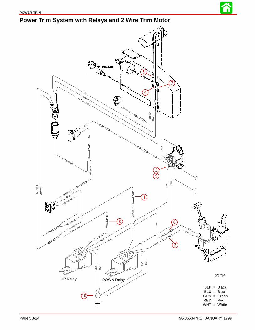
POWER TRIM
Page 5B-14 90-855347R1 JANUARY 1999
Power Trim System with Relays and 2 Wire Trim Motor
BLK = BlackBLU = Blue
GRN = GreenRED = RedWHT = White
DOWN RelayUP Relay53794
1
2
3
4
5
6
7
8
9
10
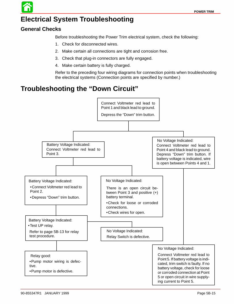
POWER TRIM
90-855347R1 JANUARY 1999 Page 5B-15
Electrical System TroubleshootingGeneral Checks
Before troubleshooting the Power Trim electrical system, check the following:
1. Check for disconnected wires.
2. Make certain all connections are tight and corrosion free.
3. Check that plug-in connectors are fully engaged.
4. Make certain battery is fully charged.
Refer to the preceding four wiring diagrams for connection points when troubleshootingthe electrical systems (Connection points are specified by number.)
Troubleshooting the “Down Circuit”
Battery Voltage Indicated:
Battery Voltage Indicated:
Relay good:
No Voltage Indicated:
No Voltage Indicated:
No Voltage Indicated:
No Voltage Indicated:
Connect Voltmeter red lead toPoint 5. If battery voltage is indi-cated, trim switch is faulty. If nobattery voltage, check for looseor corroded connection at Point5 or open circuit in wire supply-ing current to Point 5.
Relay Switch is defective.
There is an open circuit be-tween Point 3 and positive (+)battery terminal.
•Connect Voltmeter red lead toPoint 2.
Connect Voltmeter red lead toPoint 3.
Connect Voltmeter red lead toPoint 4 and black lead to ground.Depress “Down” trim button. Ifbattery voltage is indicated, wireis open between Points 4 and 1.
Connect Voltmeter red lead toPoint 1 and black lead to ground.
Depress the “Down” trim button.
•Depress “Down” trim button.
•Pump motor wiring is defec-tive.•Pump motor is defective.
•Check for loose or corrodedconnections.•Check wires for open.
Battery Voltage Indicated:•Test UP relay.
Refer to page 5B-13 for relaytest procedure.

POWER TRIM
Page 5B-16 90-855347R1 JANUARY 1999
Troubleshooting the “Up” Circuit
Battery Voltage Indicated:
Battery Voltage Indicated:
No Voltage Indicated:
No Voltage Indicated:
No Voltage Indicated:
No Voltage Indicated:
Connect Voltmeter red lead toPoint 5. If battery voltage is indi-cated, trim switch is faulty. If nobattery voltage, check for looseor corroded connection at Point5 or open circuit in wire supply-ing current to Point 5.
Relay Switch is defective.
There is an open circuit be-tween Point 9 and positive (+)battery terminal.
•Connect Voltmeter red lead toPoint 6.
Connect Voltmeter red lead toPoint 9.
Connect Voltmeter red lead toPoint 7 and black lead to ground.Depress “Up” trim button. If bat-tery voltage is indicated, wire isopen between Points 7 and 8.
Connect Voltmeter red lead toPoint 8 and black lead to ground.
Depress the “Up” trim button.
•Depress “Up” trim button.
•Pump motor wiring is defec-tive.
•Pump motor is defective.
•Check for loose or corrodedconnections.•Check wires for open.
Battery Voltage Indicated:•Test DOWN relay.
Refer to page 5B-13 for relaytest procedure.
Relay good:
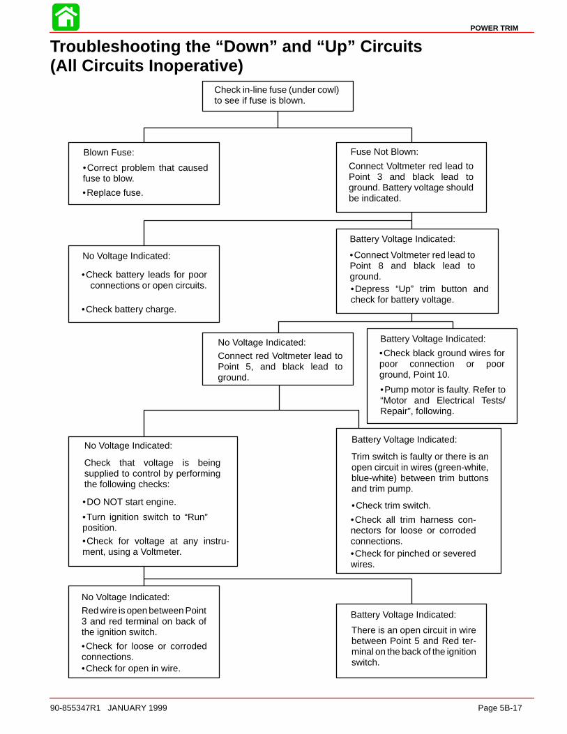
POWER TRIM
90-855347R1 JANUARY 1999 Page 5B-17
Troubleshooting the “Down” and “Up” Circuits(All Circuits Inoperative)
Battery Voltage Indicated:
No Voltage Indicated:
Battery Voltage Indicated:
Battery Voltage Indicated:
Battery Voltage Indicated:
No Voltage Indicated:
No Voltage Indicated:
No Voltage Indicated:
Blown Fuse: Fuse Not Blown:
Check in-line fuse (under cowl)to see if fuse is blown.
•Correct problem that causedfuse to blow.
•Replace fuse.
•Check battery leads for poorconnections or open circuits.
•Check battery charge.
•Connect Voltmeter red lead toPoint 8 and black lead toground.•Depress “Up” trim button andcheck for battery voltage.
•Check black ground wires forpoor connection or poorground, Point 10.
•Pump motor is faulty. Refer to“Motor and Electrical Tests/Repair”, following.
•Check for open in wire.
•Check for loose or corrodedconnections.
•Check for voltage at any instru-ment, using a Voltmeter.
•Turn ignition switch to “Run”position.
•DO NOT start engine.
•Check for pinched or severedwires.
•Check all trim harness con-nectors for loose or corrodedconnections.
•Check trim switch.
Connect Voltmeter red lead toPoint 3 and black lead toground. Battery voltage shouldbe indicated.
There is an open circuit in wirebetween Point 5 and Red ter-minal on the back of the ignitionswitch.
Red wire is open between Point3 and red terminal on back ofthe ignition switch.
Check that voltage is beingsupplied to control by performingthe following checks:
Connect red Voltmeter lead toPoint 5, and black lead toground.
Trim switch is faulty or there is anopen circuit in wires (green-white,blue-white) between trim buttonsand trim pump.
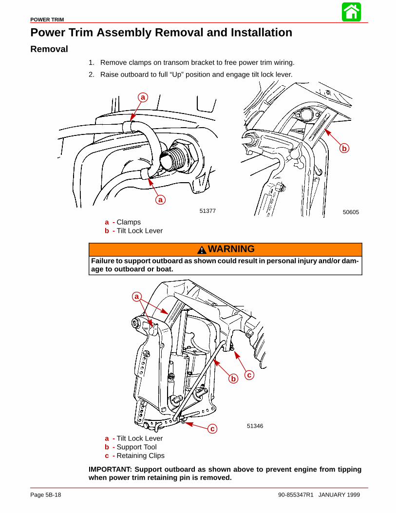
POWER TRIM
Page 5B-18 90-855347R1 JANUARY 1999
Power Trim Assembly Removal and InstallationRemoval
1. Remove clamps on transom bracket to free power trim wiring.
2. Raise outboard to full “Up” position and engage tilt lock lever.
50605
b
51377
a
a
a - Clampsb - Tilt Lock Lever
WARNINGFailure to support outboard as shown could result in personal injury and/or dam-age to outboard or boat.
51346
b c
c
a
a - Tilt Lock Leverb - Support Toolc - Retaining Clips
IMPORTANT: Support outboard as shown above to prevent engine from tippingwhen power trim retaining pin is removed.
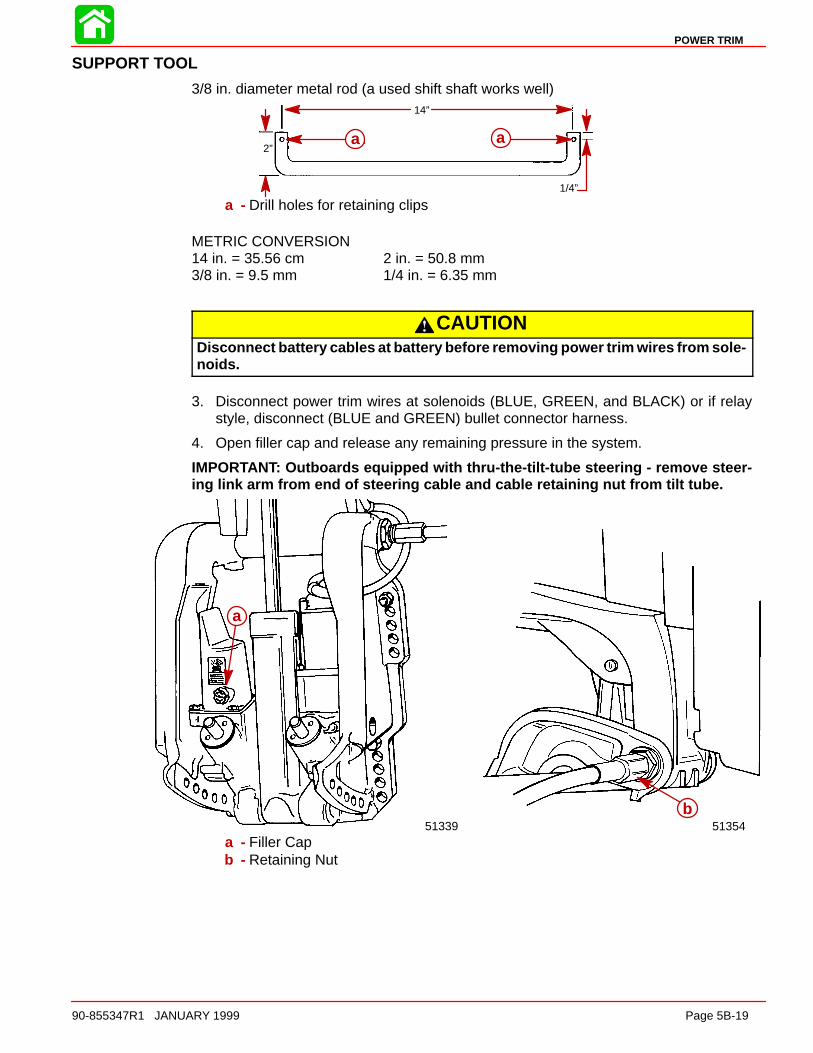
POWER TRIM
90-855347R1 JANUARY 1999 Page 5B-19
SUPPORT TOOL
3/8 in. diameter metal rod (a used shift shaft works well)14”
2”
1/4”
a aa a
a - Drill holes for retaining clips
METRIC CONVERSION14 in. = 35.56 cm 2 in. = 50.8 mm3/8 in. = 9.5 mm 1/4 in. = 6.35 mm
CAUTIONDisconnect battery cables at battery before removing power trim wires from sole-noids.
3. Disconnect power trim wires at solenoids (BLUE, GREEN, and BLACK) or if relaystyle, disconnect (BLUE and GREEN) bullet connector harness.
4. Open filler cap and release any remaining pressure in the system.
IMPORTANT: Outboards equipped with thru-the-tilt-tube steering - remove steer-ing link arm from end of steering cable and cable retaining nut from tilt tube.
b
a
51339 51354a - Filler Capb - Retaining Nut

POWER TRIM
Page 5B-20 90-855347R1 JANUARY 1999
5. Remove outboard transom mounting bolts, and loosen tilt tube nut until nut is flushwith end of tilt tube thread.
6. Remove 3 screws and washers and move starboard transom bracket.
5137551375
c d
a
b
a
a - Transom Mount Bolts (2)b - Tilt Tube Nut (flush with end of thread)c - Screws (3)d - Washers (3)
IMPORTANT: Cross pin (a) should not be reused. Replace with new cross pin.
7. Drive out cross pin, push out upper swivel pin, and remove 3 screws and washersretaining trim system. Remove system from outboard.
a b
c
51339a - Cross Pinb - Upper Swivel Pinc - Port Transom Bracket Screws and Washers (3). Remove to Release Trim
System from Outboard.

POWER TRIM
90-855347R1 JANUARY 1999 Page 5B-21
Installation1. Paint any exposed metal surfaces to prevent corrosion.
2. Apply Loctite 271 to screws. Install trim system, starboard transom bracket, and tilttube nut.
3. Use a 12 volt power source to extend tilt ram up to align upper swivel shaft hole andend of ram. Connect trim motor wires [BLUE wire to POSITIVE (+), BLACK wire toNEGATIVE (–)]. If ram extends too far, retract ram by connecting GREEN wire to POS-ITIVE (+).
4. Install Upper Swivel Pin with slotted end to left (port) side of engine.
de
f
51375
a b
c
a - Screw (6) Torque to 40 lb. ft. (54.0 N·m)b - Lockwasher (6) Install one per screwc - Tilt Tube Nutd - Upper Swivel Pine - Slotted endf - Cross hole (in line with slotted end)
IMPORTANT: Cross pin should not be reused. Install a new pin.
5. Position slot on end of swivel shaft in line with hole in tilt ram end. Insert a punch intotilt ram hole to align cross hole in upper swivel shaft. Tap new cross pin in until flush.
a
d
bc
a - Upper Swivel Shaft (Slot is in line with cross hole)b - Chamfered End of Hole (Faces away from transom)c - Retaining Pind - Tilt Ram End
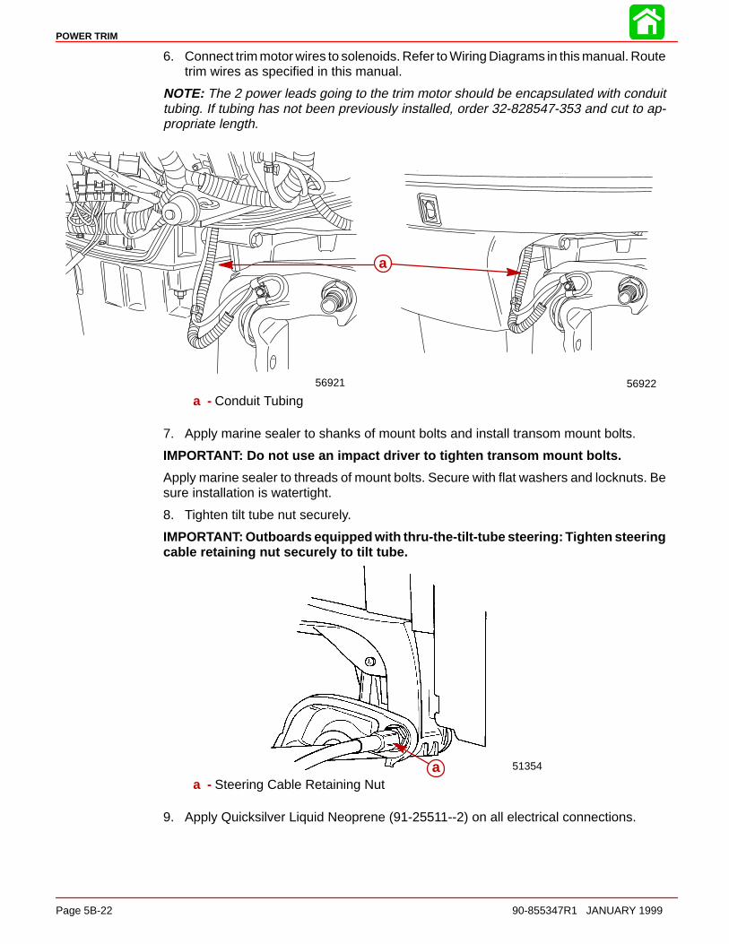
POWER TRIM
Page 5B-22 90-855347R1 JANUARY 1999
6. Connect trim motor wires to solenoids. Refer to Wiring Diagrams in this manual. Routetrim wires as specified in this manual.
NOTE: The 2 power leads going to the trim motor should be encapsulated with conduittubing. If tubing has not been previously installed, order 32-828547-353 and cut to ap-propriate length.
56921 56922
a
a - Conduit Tubing
7. Apply marine sealer to shanks of mount bolts and install transom mount bolts.
IMPORTANT: Do not use an impact driver to tighten transom mount bolts.
Apply marine sealer to threads of mount bolts. Secure with flat washers and locknuts. Besure installation is watertight.
8. Tighten tilt tube nut securely.
IMPORTANT: Outboards equipped with thru-the-tilt-tube steering: Tighten steeringcable retaining nut securely to tilt tube.
51354aa - Steering Cable Retaining Nut
9. Apply Quicksilver Liquid Neoprene (91-25511--2) on all electrical connections.
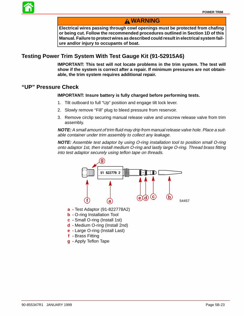
POWER TRIM
90-855347R1 JANUARY 1999 Page 5B-23
WARNINGElectrical wires passing through cowl openings must be protected from chafingor being cut. Follow the recommended procedures outlined in Section 1D of thisManual. Failure to protect wires as described could result in electrical system fail-ure and/or injury to occupants of boat.
Testing Power Trim System With Test Gauge Kit (91-52915A6)IMPORTANT: This test will not locate problems in the trim system. The test willshow if the system is correct after a repair. If minimum pressures are not obtain-able, the trim system requires additional repair.
“UP” Pressure CheckIMPORTANT: Insure battery is fully charged before performing tests.
1. Tilt outboard to full “Up” position and engage tilt lock lever.
2. Slowly remove “Fill” plug to bleed pressure from reservoir.
3. Remove circlip securing manual release valve and unscrew release valve from trimassembly.
NOTE: A small amount of trim fluid may drip from manual release valve hole. Place a suit-able container under trim assembly to collect any leakage.
NOTE: Assemble test adaptor by using O-ring installation tool to position small O-ringonto adaptor 1st, then install medium O-ring and lastly large O-ring. Thread brass fittinginto test adaptor securely using teflon tape on threads.
f e d c b54457a
bcdef
g
a - Test Adaptor (91-822778A2)b - O-ring Installation Toolc - Small O-ring (Install 1st)d - Medium O-ring (Install 2nd)e - Large O-ring (Install Last)f - Brass Fittingg - Apply Teflon Tape
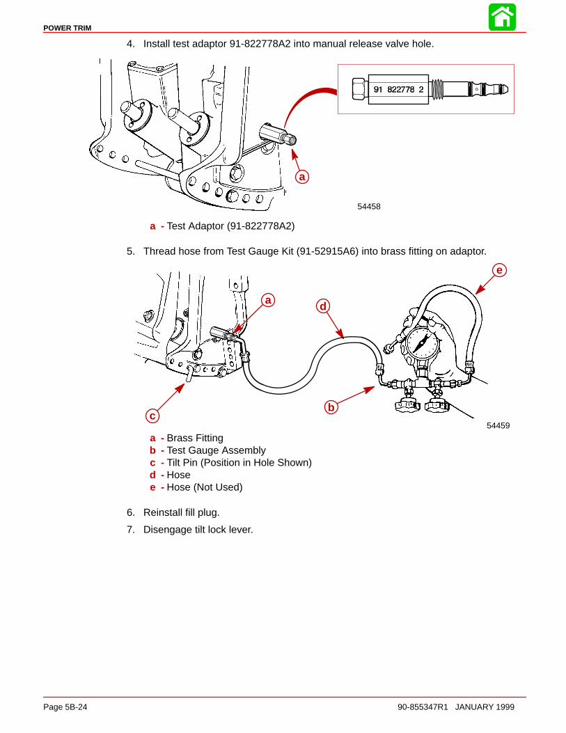
POWER TRIM
Page 5B-24 90-855347R1 JANUARY 1999
4. Install test adaptor 91-822778A2 into manual release valve hole.
a
54458
a - Test Adaptor (91-822778A2)
5. Thread hose from Test Gauge Kit (91-52915A6) into brass fitting on adaptor.
a
bc
d
e
54459
a - Brass Fittingb - Test Gauge Assemblyc - Tilt Pin (Position in Hole Shown)d - Hosee - Hose (Not Used)
6. Reinstall fill plug.
7. Disengage tilt lock lever.

POWER TRIM
90-855347R1 JANUARY 1999 Page 5B-25
CAUTIONFailure to install spare tilt pin (or hardened bolts and nuts) in hole shown couldresult in transom bracket failure and possible injury.
8. Move outboard “IN” until hole in swivel bracket “ear” aligns with the 3rd tilt hole in tran-som bracket. Lock engine in trim range by installing a 3/8 in. (9.5 mm) diameter tilt pinor two 3/8 in. (9.5 mm) hardened bolts and nuts thru the transom brackets and swivelbracket in the hole shown.
a 54460
a - Tilt Pin Hole (Install Spare Tilt Pin or Hardened Bolts and Nuts)
9. Open valve (a) and close valve (b).
a b
51374
10. Run trim “UP”. The minimum pressure should be 1300 P.S.I. (91 kg/cm2).
11. Run trim “DOWN” to release pressure and remove spare tilt pin or bolts and nuts.
12. Tilt outboard full “UP” and engage tilt lock lever.
13. Slowly remove “Fill” plug to bleed pressure.
14. Remove test gauge hose and adapter.
15. Reinstall Manual Release Valve and secure valve with circlip.
16. Retighten “Fill” plug.
NOTE: If pressure is less than 1300 PSI (91 kg/cm2), troubleshoot system per instructionson page 5B-16.
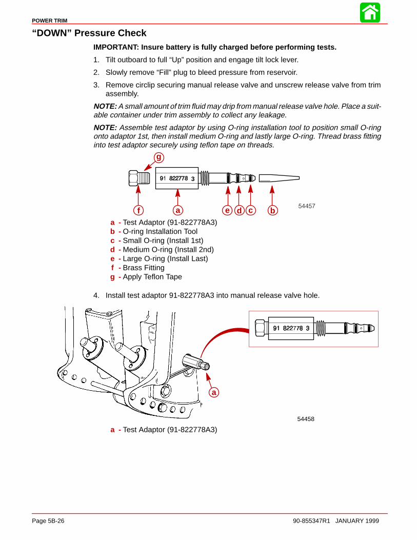
POWER TRIM
Page 5B-26 90-855347R1 JANUARY 1999
“DOWN” Pressure CheckIMPORTANT: Insure battery is fully charged before performing tests.
1. Tilt outboard to full “Up” position and engage tilt lock lever.
2. Slowly remove “Fill” plug to bleed pressure from reservoir.
3. Remove circlip securing manual release valve and unscrew release valve from trimassembly.
NOTE: A small amount of trim fluid may drip from manual release valve hole. Place a suit-able container under trim assembly to collect any leakage.
NOTE: Assemble test adaptor by using O-ring installation tool to position small O-ringonto adaptor 1st, then install medium O-ring and lastly large O-ring. Thread brass fittinginto test adaptor securely using teflon tape on threads.
3
f a e d c b
g
a - Test Adaptor (91-822778A3)b - O-ring Installation Toolc - Small O-ring (Install 1st)d - Medium O-ring (Install 2nd)e - Large O-ring (Install Last)f - Brass Fittingg - Apply Teflon Tape
4. Install test adaptor 91-822778A3 into manual release valve hole.
a
54458
a - Test Adaptor (91-822778A3)
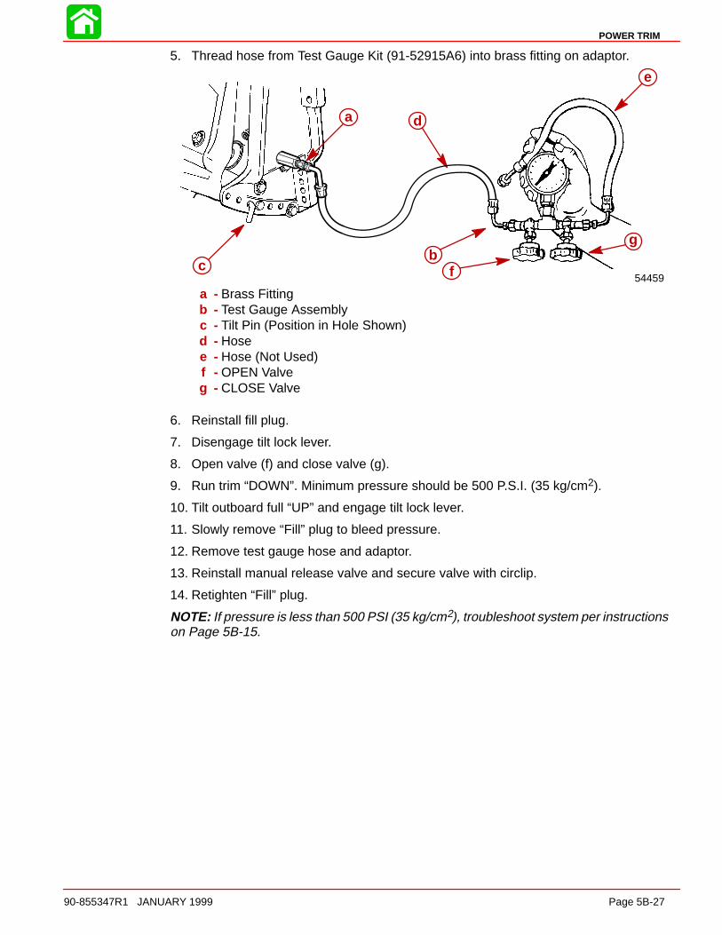
POWER TRIM
90-855347R1 JANUARY 1999 Page 5B-27
5. Thread hose from Test Gauge Kit (91-52915A6) into brass fitting on adaptor.
a
bc
d
e
f
g
54459
a - Brass Fittingb - Test Gauge Assemblyc - Tilt Pin (Position in Hole Shown)d - Hosee - Hose (Not Used)f - OPEN Valveg - CLOSE Valve
6. Reinstall fill plug.
7. Disengage tilt lock lever.
8. Open valve (f) and close valve (g).
9. Run trim “DOWN”. Minimum pressure should be 500 P.S.I. (35 kg/cm2).
10. Tilt outboard full “UP” and engage tilt lock lever.
11. Slowly remove “Fill” plug to bleed pressure.
12. Remove test gauge hose and adaptor.
13. Reinstall manual release valve and secure valve with circlip.
14. Retighten “Fill” plug.
NOTE: If pressure is less than 500 PSI (35 kg/cm2), troubleshoot system per instructionson Page 5B-15.
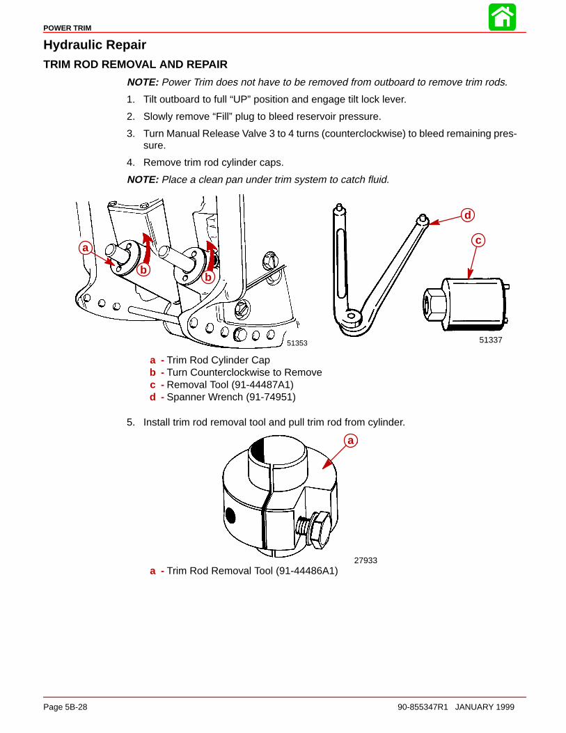
POWER TRIM
Page 5B-28 90-855347R1 JANUARY 1999
Hydraulic RepairTRIM ROD REMOVAL AND REPAIR
NOTE: Power Trim does not have to be removed from outboard to remove trim rods.
1. Tilt outboard to full “UP” position and engage tilt lock lever.
2. Slowly remove “Fill” plug to bleed reservoir pressure.
3. Turn Manual Release Valve 3 to 4 turns (counterclockwise) to bleed remaining pres-sure.
4. Remove trim rod cylinder caps.
NOTE: Place a clean pan under trim system to catch fluid.
c
d
a
bb
5133751353
a - Trim Rod Cylinder Capb - Turn Counterclockwise to Removec - Removal Tool (91-44487A1)d - Spanner Wrench (91-74951)
5. Install trim rod removal tool and pull trim rod from cylinder.
aa
27933a - Trim Rod Removal Tool (91-44486A1)

POWER TRIM
90-855347R1 JANUARY 1999 Page 5B-29
CLEANING AND INSPECTION - TRIM RODS AND CAPS
CAUTIONDo not remove check valve (a). Check valve is preset to operate at a specific pres-sure. Removal and installation of check valve could result in improper operatingpressure and possible system damage.
NOTE: Check valve is in port side trim rod only.
1. Inspect check valve and check valve screen for debris; if debris cannot be removed,replace trim rod assembly. Clean trim rod with parts cleaner and dry with compressedair.
51352
a
ba - Check Valveb - Check Valve Screen
Trim Rod End Cap Seal1. Inspect trim cap end seal and replace if damaged or if seal does not keep trim rod
clean.a
51343a - Seal (remove as shown)
2. Install new seal with seal lip up.
TRIM ROD INSTALLATION
IMPORTANT: Components must be free of dirt and lint. Any debris in the systemcan cause system to malfunction.
NOTE: Install trim rod with check valve in the port (left) cylinder.
1. Apply Quicksilver Power Trim and Steering Fluid on all O-rings and seals before in-stallation.
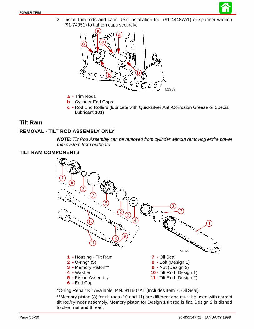
POWER TRIM
Page 5B-30 90-855347R1 JANUARY 1999
2. Install trim rods and caps. Use installation tool (91-44487A1) or spanner wrench(91-74951) to tighten caps securely.
aa
b b
c c
51353
a - Trim Rodsb - Cylinder End Capsc - Rod End Rollers (lubricate with Quicksilver Anti-Corrosion Grease or Special
Lubricant 101)
Tilt RamREMOVAL - TILT ROD ASSEMBLY ONLY
NOTE: Tilt Rod Assembly can be removed from cylinder without removing entire powertrim system from outboard.
TILT RAM COMPONENTS
51372
1
23
42
2
5
22
67
8 911
10
1 - Housing - Tilt Ram2 - O-ring* (5)3 - Memory Piston**4 - Washer5 - Piston Assembly6 - End Cap
7 - Oil Seal8 - Bolt (Design 1)9 - Nut (Design 2)
10 - Tilt Rod (Design 1)11 - Tilt Rod (Design 2)
*O-ring Repair Kit Available, P.N. 811607A1 (Includes item 7, Oil Seal)**Memory piston (3) for tilt rods (10 and 11) are different and must be used with correcttilt rod/cylinder assembly. Memory piston for Design 1 tilt rod is flat, Design 2 is dishedto clear nut and thread.

POWER TRIM
90-855347R1 JANUARY 1999 Page 5B-31
TILT RAM REMOVAL - POWER TRIM SYSTEM REMOVED FROM OUTBOARD
CAUTIONInsure trim system is depressurized prior to tilt ram removal.
1. Remove cross pin.
2. Remove lower swivel pin.
51355
51366a
b
a - Cross Pin (Remove as shown)b - Lower Swivel Pin (Remove as shown)
Disassembly1. Secure tilt ram in a soft jawed vise. Remove tilt rod and cap.
51364
51337
91-74951
a
b
c
a - Cap (Turn Counterclockwise to Remove)b - Spanner Wrench (91-74951)c - Tilt Rod - Pull to Remove

POWER TRIM
Page 5B-32 90-855347R1 JANUARY 1999
2. Clamp tilt rod in a soft jawed vise. Remove bolt or nut as applicable to disassemblerod assembly. Remove O-ring.
51378
51340
a
b
a - Bolt (Design 1) or Stud/Nut (Design 2)b - O-Ring
IMPORTANT: Note Design 1 and 2 on page 5B-31. Design 1 tilt rod assembly re-places either tilt rod assembly. Either design will fit as a (replace) cylinder assem-bly complete.Design 2 will NOT fit a cylinder originally using a Design 1 tilt rod assembly.Memory Pistons for Design 1 and 2 differ also and must be used only on the cylin-der the piston was removed from.
3. Remove washer, check valve assemblies, and piston.
NOTE: Check valve held in by roll pin can be cleaned but not removed.
51363
a
b
c
a - Washerb - Check Valve Assembly (7)c - Piston
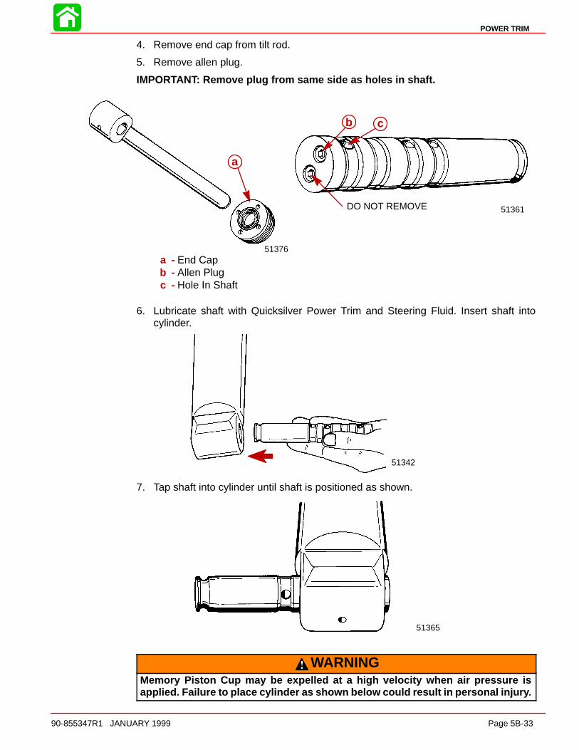
POWER TRIM
90-855347R1 JANUARY 1999 Page 5B-33
4. Remove end cap from tilt rod.
5. Remove allen plug.
IMPORTANT: Remove plug from same side as holes in shaft.
51361DO NOT REMOVE
51376
a
b c
a - End Capb - Allen Plugc - Hole In Shaft
6. Lubricate shaft with Quicksilver Power Trim and Steering Fluid. Insert shaft intocylinder.
51342
7. Tap shaft into cylinder until shaft is positioned as shown.
51365
WARNINGMemory Piston Cup may be expelled at a high velocity when air pressure isapplied. Failure to place cylinder as shown below could result in personal injury.
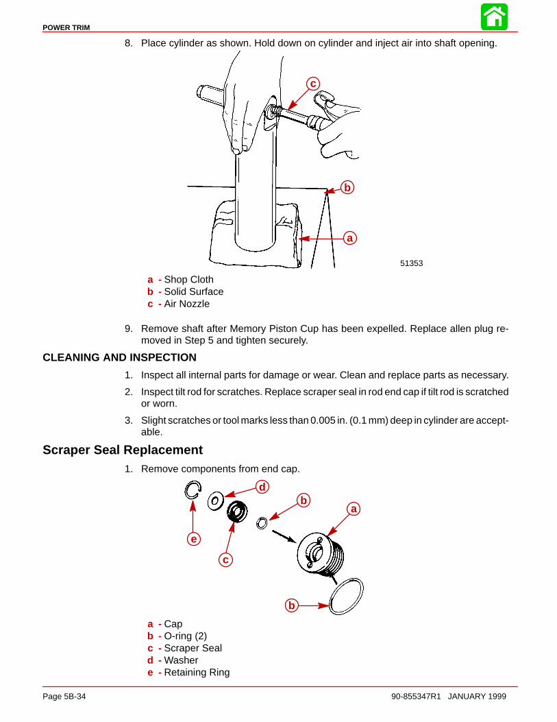
POWER TRIM
Page 5B-34 90-855347R1 JANUARY 1999
8. Place cylinder as shown. Hold down on cylinder and inject air into shaft opening.
51353
c
b
a
a - Shop Clothb - Solid Surfacec - Air Nozzle
9. Remove shaft after Memory Piston Cup has been expelled. Replace allen plug re-moved in Step 5 and tighten securely.
CLEANING AND INSPECTION
1. Inspect all internal parts for damage or wear. Clean and replace parts as necessary.
2. Inspect tilt rod for scratches. Replace scraper seal in rod end cap if tilt rod is scratchedor worn.
3. Slight scratches or tool marks less than 0.005 in. (0.1 mm) deep in cylinder are accept-able.
Scraper Seal Replacement1. Remove components from end cap.
a
b
b
c
d
e
a - Capb - O-ring (2)c - Scraper Seald - Washere - Retaining Ring

POWER TRIM
90-855347R1 JANUARY 1999 Page 5B-35
REASSEMBLY
IMPORTANT: Components must be clean for reassembly. Any debris in the systemcan cause the system to malfunction.
NOTE: Refer to “Tilt Ram Components” for proper O-ring sizes.
1. Apply Quicksilver Power Trim and Steering Fluid on O-rings prior to reassembly.
2. Install O-ring on Memory Piston Cup and install in cylinder.
51372a
b
a - O-ringb - Memory Piston Cup (Design 1 shown)
3. Assemble end cap.
4. Install end cap.
51376
f
a
b
b
c
d
e
a - End Capb - O-ring (2)c - Scraper seald - Washere - Retaining Ringf - End Cap

POWER TRIM
Page 5B-36 90-855347R1 JANUARY 1999
5. Install components on rod.
51340
51363
ab
c
c
de
a - Pistonb - O-ringc - Check Valve Assembly (7)d - Washere - Bolt or Locknut. (Tighten securely)
6. Clamp cylinder in a soft jawed vise and install tilt rod assembly. Use spanner wrenchand tighten end cap securely.
51341
51337
91-74951
a
b
c
a - Cylinderb - Tilt Rod Assemblyc - End Cap (Tighten Securely.) Use Spanner Wrench.
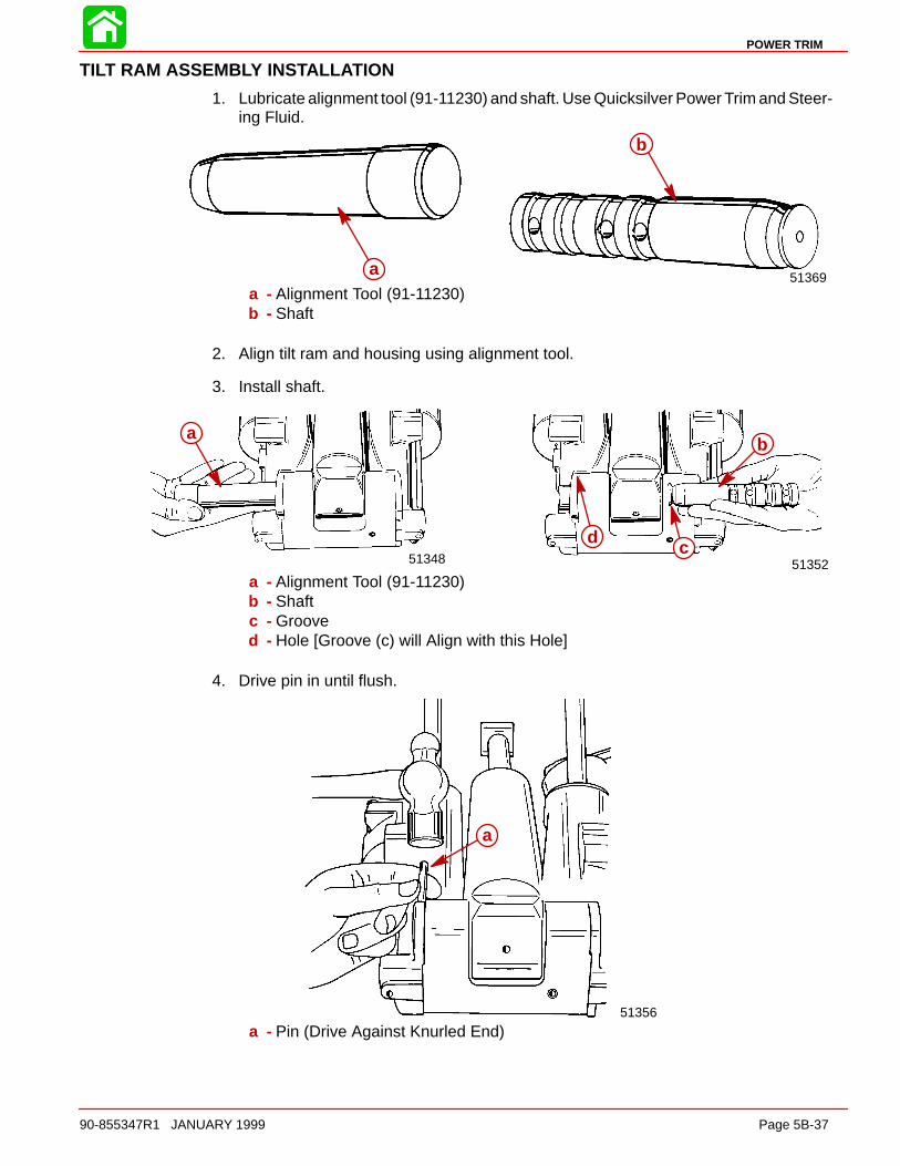
POWER TRIM
90-855347R1 JANUARY 1999 Page 5B-37
TILT RAM ASSEMBLY INSTALLATION
1. Lubricate alignment tool (91-11230) and shaft. Use Quicksilver Power Trim and Steer-ing Fluid.
51369a
b
a - Alignment Tool (91-11230)b - Shaft
2. Align tilt ram and housing using alignment tool.
3. Install shaft.
5135251348
b
cd
a
a - Alignment Tool (91-11230)b - Shaftc - Grooved - Hole [Groove (c) will Align with this Hole]
4. Drive pin in until flush.
51356
a
a - Pin (Drive Against Knurled End)

POWER TRIM
Page 5B-38 90-855347R1 JANUARY 1999
Motor and Electrical Tests/Repair
Trim Pump Motor Test
WARNINGDo not perform this test near flammable materials, as a spark may occur whilemaking electrical connections.
1. Connect a 12 volt power supply to motor wires; one motor lead to POSITIVE (+) bat-tery terminal and the other motor lead to the NEGATIVE (–) battery terminal. Motorshould run. Reverse motor leads between battery terminals. Motor should run.
53774
2. If motor does not run, disassemble and check components.
Motor Disassembly1. Remove 2 screws.
53774
a a
a - Screw (2)

POWER TRIM
90-855347R1 JANUARY 1999 Page 5B-39
2. Remove frame and armature from end cap. Use care not to drop armature.
53779
a bc
a - Frameb - Armaturec - End Cap
Armature TestsTEST FOR SHORTS
Check armature on a Growler per the Growler manufacturer’s instructions. Replace ar-mature if a short is indicated.
TEST FOR GROUND
1. Use an Ohmmeter (Rx1 scale). Connect one lead on armature shaft and other leadon commutator. If continuity is indicated, armature is grounded. Replace armature.
53786

POWER TRIM
Page 5B-40 90-855347R1 JANUARY 1999
CHECKING AND CLEANING COMMUTATOR
1. If commutator is worn it may be turned on an armature conditioner or a lathe.
2. Clean commutator with “OO” sandpaper.
53775
a
a - Commutator
FIELD TESTS
IMPORTANT: Commutator end of armature must be installed in brushes when per-forming the following tests.
OhmmeterLeads Between
Resistance(Ohms)
Scale Reading*(x____________)
BLUE and BLACK Motor Wires 0 (Rx1)
BLACK Motor Wire, and Frame(Motor Housing)
No Continuity (Rx1)
BLUE Motor Wire and Frame No Continuity (Rx1)
*If specified readings are not obtained, check for:
• defective armature
• dirty or worn brushes
• dirty or worn commutator
If defective components are found, repair or replace component(s) and retest.
Motor RepairREMOVAL
NOTE: Power Trim System does not have to be removed from outboard to repair/replacemotor.
DISASSEMBLY
Refer to “Motor Disassembly” on page 5B-38 to disassemble motor from pump.

POWER TRIM
90-855347R1 JANUARY 1999 Page 5B-41
CLEANING AND INSPECTION
Inspect O-rings and replace if necessary. Carefully inspect power cord for cuts or tearswhich will allow water to enter motor. Replace cord if cut or torn. Clean, inspect, and testmotor components. Refer to “Brush Replacement” , “Armature Test”, and “FieldTests” for inspection and test procedures.
53779
a b
c
d
e
a - Frameb - Armaturec - Shimd - Brush Card Assemblye - O-rings
BRUSH REPLACEMENT
1. Brush replacement is required if brushes are pitted, chipped, or if distance (a) be-tween the brush pigtail and end of brush holder slot is 1/16 in. or less. Check distancewith armature installed.
53784
a
a - 1/16 in.

POWER TRIM
Page 5B-42 90-855347R1 JANUARY 1999
2. To replace brush card, disconnect spade terminal.
3. Cut crimped brush lead.
4. Remove 2 screws securing brush card to end cap.
a
b
c
a - Spade Terminalb - Crimped Brush Leadc - Screws
5. Install new brush card (BRUSH and SEAL KIT 828714A1).
6. Crimp metal connector onto motor lead and new brush lead.
7. Connect spade connector motor lead to brush card connector.
8. Secure brush card to end cap with 2 screws and lockwashers.
9. Inspect O-ring for cuts and abrasions. Replace O-ring as required (BRUSH and SEALKIT 828714A1).
53778
a
b
c d
e
a - Brush Cardb - Metal Connectorc - Spade Connectord - Screws and Lockwasherse - O-ring
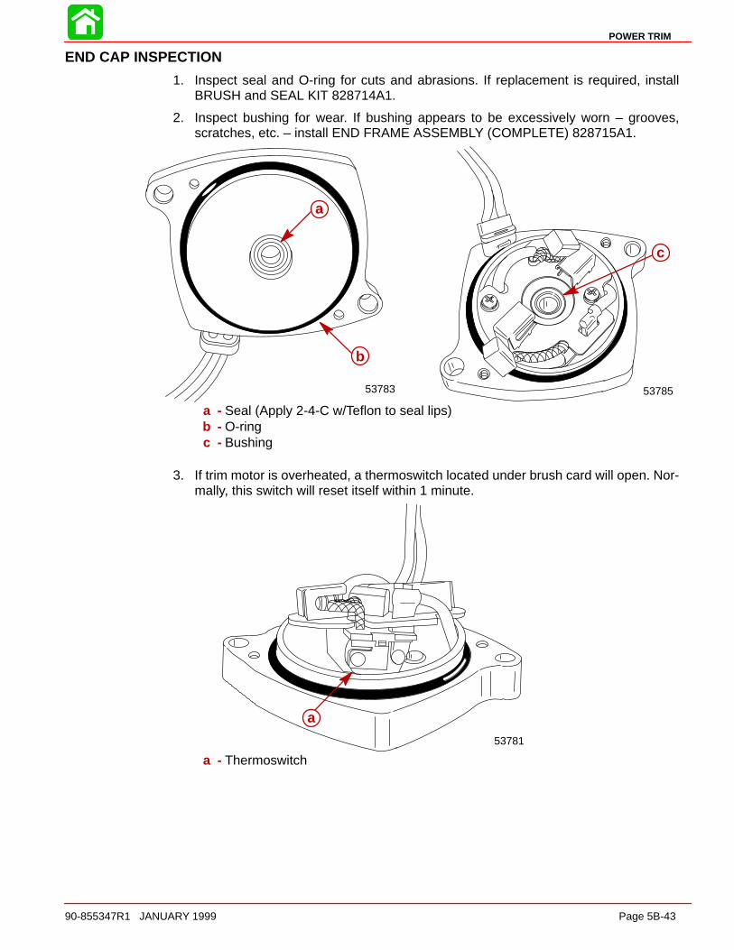
POWER TRIM
90-855347R1 JANUARY 1999 Page 5B-43
END CAP INSPECTION
1. Inspect seal and O-ring for cuts and abrasions. If replacement is required, installBRUSH and SEAL KIT 828714A1.
2. Inspect bushing for wear. If bushing appears to be excessively worn – grooves,scratches, etc. – install END FRAME ASSEMBLY (COMPLETE) 828715A1.
53785
c
53783
a
b
a - Seal (Apply 2-4-C w/Teflon to seal lips)b - O-ringc - Bushing
3. If trim motor is overheated, a thermoswitch located under brush card will open. Nor-mally, this switch will reset itself within 1 minute.
53781
a
a - Thermoswitch
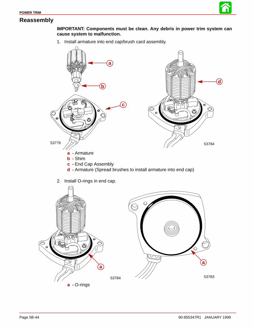
POWER TRIM
Page 5B-44 90-855347R1 JANUARY 1999
ReassemblyIMPORTANT: Components must be clean. Any debris in power trim system cancause system to malfunction.
1. Install armature into end cap/brush card assembly.
53779 53784
a
b
c
d
a - Armatureb - Shimc - End Cap Assemblyd - Armature (Spread brushes to install armature into end cap)
2. Install O-rings in end cap.
53784 53783
aa
a - O-rings
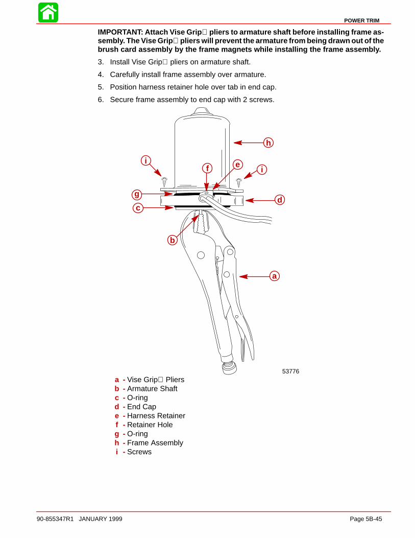
POWER TRIM
90-855347R1 JANUARY 1999 Page 5B-45
IMPORTANT: Attach Vise Grip pliers to armature shaft before installing frame as-sembly. The Vise Grip pliers will prevent the armature from being drawn out of thebrush card assembly by the frame magnets while installing the frame assembly.
3. Install Vise Grip pliers on armature shaft.
4. Carefully install frame assembly over armature.
5. Position harness retainer hole over tab in end cap.
6. Secure frame assembly to end cap with 2 screws.
53776
a
b
cd
e
g
h
iif
a - Vise Grip Pliersb - Armature Shaftc - O-ringd - End Cape - Harness Retainerf - Retainer Holeg - O-ringh - Frame Assemblyi - Screws
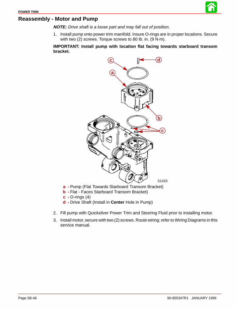
POWER TRIM
Page 5B-46 90-855347R1 JANUARY 1999
Reassembly - Motor and PumpNOTE: Drive shaft is a loose part and may fall out of position.
1. Install pump onto power trim manifold. Insure O-rings are in proper locations. Securewith two (2) screws. Torque screws to 80 lb. in. (9 N·m).
IMPORTANT: Install pump with location flat facing towards starboard transombracket.
51433
a
b
c
dc
a - Pump (Flat Towards Starboard Transom Bracket)b - Flat - Faces Starboard Transom Bracket)c - O-rings (4)d - Drive Shaft (Install in Center Hole in Pump)
2. Fill pump with Quicksilver Power Trim and Steering Fluid prior to installing motor.
3. Install motor, secure with two (2) screws. Route wiring; refer to Wiring Diagrams in thisservice manual.
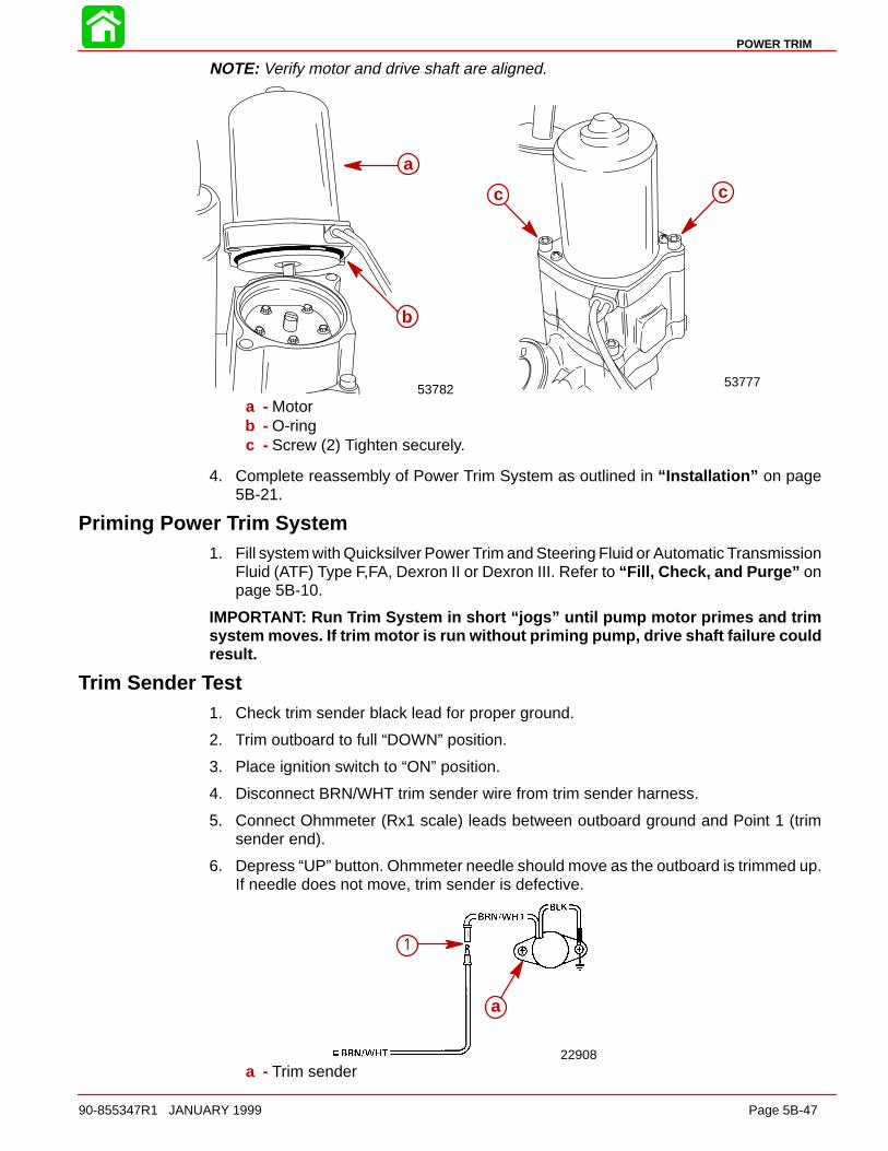
POWER TRIM
90-855347R1 JANUARY 1999 Page 5B-47
NOTE: Verify motor and drive shaft are aligned.
53782 53777
a
b
c c
a - Motorb - O-ringc - Screw (2) Tighten securely.
4. Complete reassembly of Power Trim System as outlined in “Installation” on page5B-21.
Priming Power Trim System1. Fill system with Quicksilver Power Trim and Steering Fluid or Automatic Transmission
Fluid (ATF) Type F,FA, Dexron II or Dexron III. Refer to “Fill, Check, and Purge” onpage 5B-10.
IMPORTANT: Run Trim System in short “jogs” until pump motor primes and trimsystem moves. If trim motor is run without priming pump, drive shaft failure couldresult.
Trim Sender Test1. Check trim sender black lead for proper ground.
2. Trim outboard to full “DOWN” position.
3. Place ignition switch to “ON” position.
4. Disconnect BRN/WHT trim sender wire from trim sender harness.
5. Connect Ohmmeter (Rx1 scale) leads between outboard ground and Point 1 (trimsender end).
6. Depress “UP” button. Ohmmeter needle should move as the outboard is trimmed up.If needle does not move, trim sender is defective.
a
1
22908a - Trim sender
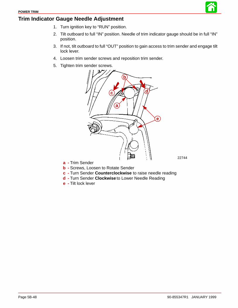
POWER TRIM
Page 5B-48 90-855347R1 JANUARY 1999
Trim Indicator Gauge Needle Adjustment1. Turn ignition key to “RUN” position.
2. Tilt outboard to full “IN” position. Needle of trim indicator gauge should be in full “IN”position.
3. If not, tilt outboard to full “OUT” position to gain access to trim sender and engage tiltlock lever.
4. Loosen trim sender screws and reposition trim sender.
5. Tighten trim sender screws.
a
b
c d
e
22744
a - Trim Senderb - Screws, Loosen to Rotate Senderc - Turn Sender Counterclockwise to raise needle readingd - Turn Sender Clockwise to Lower Needle Readinge - Tilt lock lever
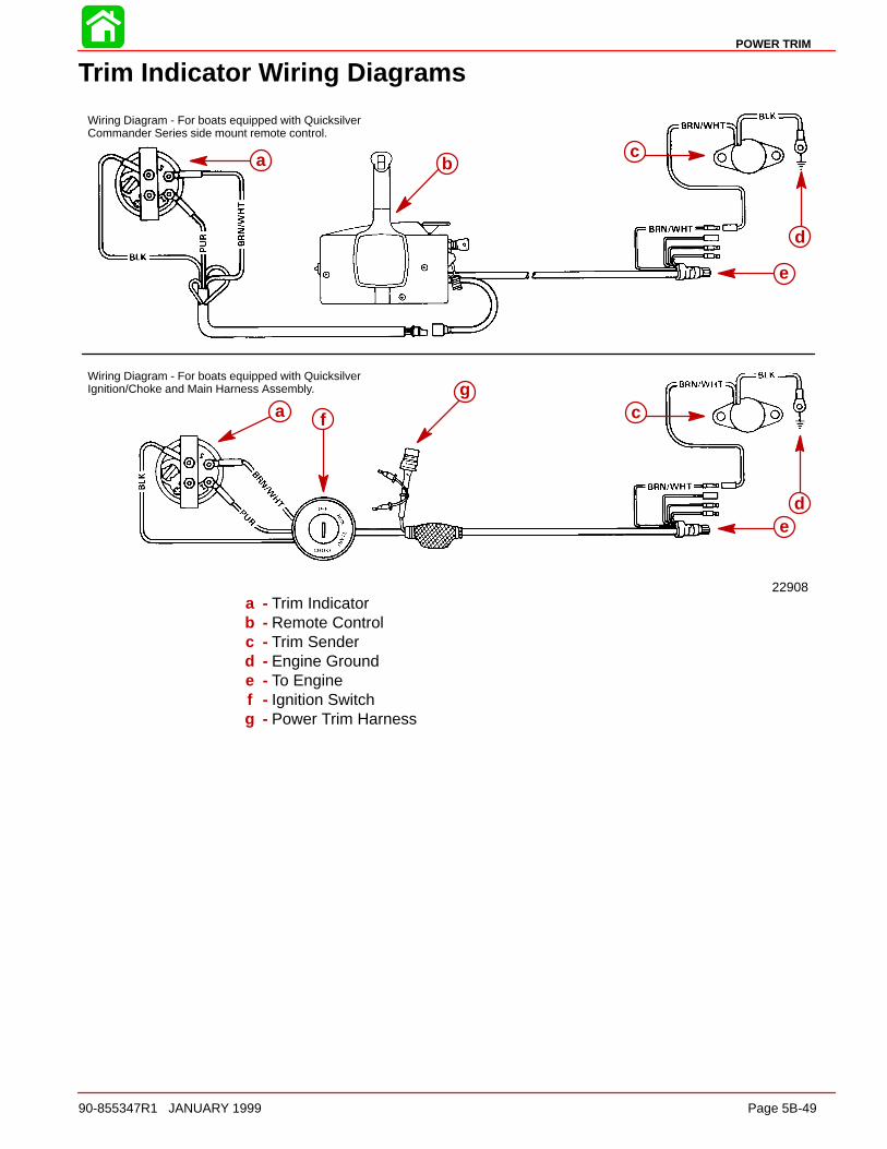
POWER TRIM
90-855347R1 JANUARY 1999 Page 5B-49
Trim Indicator Wiring Diagrams
22908
Wiring Diagram - For boats equipped with QuicksilverCommander Series side mount remote control.
Wiring Diagram - For boats equipped with QuicksilverIgnition/Choke and Main Harness Assembly.
a bc
e
d
a f
gc
ed
a - Trim Indicatorb - Remote Controlc - Trim Senderd - Engine Grounde - To Enginef - Ignition Switchg - Power Trim Harness

6A
RIGHT HAND NON-RATCHETING
90-855347R1 JANUARY 1999 Page 6A-1
LOWER UNITSection 6A – Right Hand Non-Ratcheting
Table of Contents
Gear Housing Specifications (Standard Rotation) 6A-1. Special Tools 6A-2. . . . . . . . . . . . . . . . . . . . . . . . . . . . . . . . Notes: 6A-5. . . . . . . . . . . . . . . . . . . . . . . . . . . . . . . . . . . . . . Gear Housing (Drive Shaft)(Standard Rotation) 6A-6. . Gear Housing (Prop Shaft)(Standard Rotation) 6A-8. . . General Service Recommendations 6A-10. . . . . . . . . . . Removal, Disassembly, Cleaning and Inspection– Standard Rotation 6A-11. . . . . . . . . . . . . . . . . . . . . . . . .
Removal 6A-11. . . . . . . . . . . . . . . . . . . . . . . . . . . . . . . . Draining and Inspecting Gear HousingLubricant 6A-12. . . . . . . . . . . . . . . . . . . . . . . . . . . . . . . . Water Pump 6A-13. . . . . . . . . . . . . . . . . . . . . . . . . . . . . Bearing Carrier and Propeller Shaft Removal 6A-16. Shift Shaft 6A-18. . . . . . . . . . . . . . . . . . . . . . . . . . . . . . . Propeller Shaft 6A-20. . . . . . . . . . . . . . . . . . . . . . . . . . . Clutch Actuator Rod 6A-22. . . . . . . . . . . . . . . . . . . . . . Pinion Gear and Driveshaft 6A-22. . . . . . . . . . . . . . . .
Forward Gear 6A-25. . . . . . . . . . . . . . . . . . . . . . . . . . . . Gear Housing 6A-26. . . . . . . . . . . . . . . . . . . . . . . . . . . .
Reassembly and Installation Standard Rotation 6A-26. Driveshaft Needle Bearing 6A-26. . . . . . . . . . . . . . . . . Bearing Carrier 6A-27. . . . . . . . . . . . . . . . . . . . . . . . . . . Forward Gear 6A-30. . . . . . . . . . . . . . . . . . . . . . . . . . . . Forward Gear Bearing Race 6A-31. . . . . . . . . . . . . . . Driveshaft and Pinion Gear 6A-32. . . . . . . . . . . . . . . . Pinion Gear Depth/Forward GearBacklash/Reverse Gear Backlash 6A-34. . . . . . . . . . Clutch Actuator Rod 6A-38. . . . . . . . . . . . . . . . . . . . . . Shift Shaft Bushing 6A-38. . . . . . . . . . . . . . . . . . . . . . . Propeller Shaft 6A-39. . . . . . . . . . . . . . . . . . . . . . . . . . . Water Pump 6A-42. . . . . . . . . . . . . . . . . . . . . . . . . . . . . Gear Lubricant Filling Instructions 6A-45. . . . . . . . . . Installing Gear Housing to Driveshaft Housing 6A-45Propeller Installation 6A-46. . . . . . . . . . . . . . . . . . . . . .
Gear Housing Specifications (Standard Rotation)
Ratio Pinion Depth Forward GearBacklash
Reverse GearBacklash
1.87:1
0.025 in. (0.635 mm)With Tool 91-12349A2
using Disc #2 andFlat #7
0.018 in. to 0.027 in.(0.460 mm to 0.686mm) Pointer on line
mark #1
0.030 in. to 0.050 in.(0.762 mm to 1.27 mm)
2.0:1
0.025 in. (0.635 mm)With Tool 91-12349A2
using Disc #2 andFlat #7
0.015 in. to 0.022 in.(0.38 mm to 0.56 mm)Pointer on line mark
#2
0.030 in. to 0.050 in.(0.762 mm to 1.27 mm)
2.3:1
0.025 in. (0.635 mm)With Tool 91-12349A2
using Disc #2 andFlat #7
0.018 in. to 0.023 in.(0.46 mm to 0.58 mm)Pointer on line mark
#4
0.030 in. to 0.050 in.(0.762 mm to 1.27 mm)
Gearcase Lubricant Capacity
All Ratios 22.5 fl. oz. (665.4 ml)

RIGHT HAND NON-RATCHETING
Page 6A-2 90-855347R1 JANUARY 1999
Special Tools
1. Shift Shaft Bushing Tool 91-31107
2. Gear Housing Cover Nut Tool 91-61069
3. Bearing Carrier Removal Tool 91-46086A1 and Puller Bolt 91-85716
4. Slide Hammer Puller 91-34569A1
5. Bearing Removal and Installation Kit 91-31229A5. This kit contains the followingtools: Pilot 91-36571; Puller Rod 91-31229; Nut 11-24156; Puller Plate 91-29310;Mandrel 91-38628; and Driver Rod 91-37323.
6. Pilot 91-36571
7. Puller Rod 91-31229 and Nut 91-24156
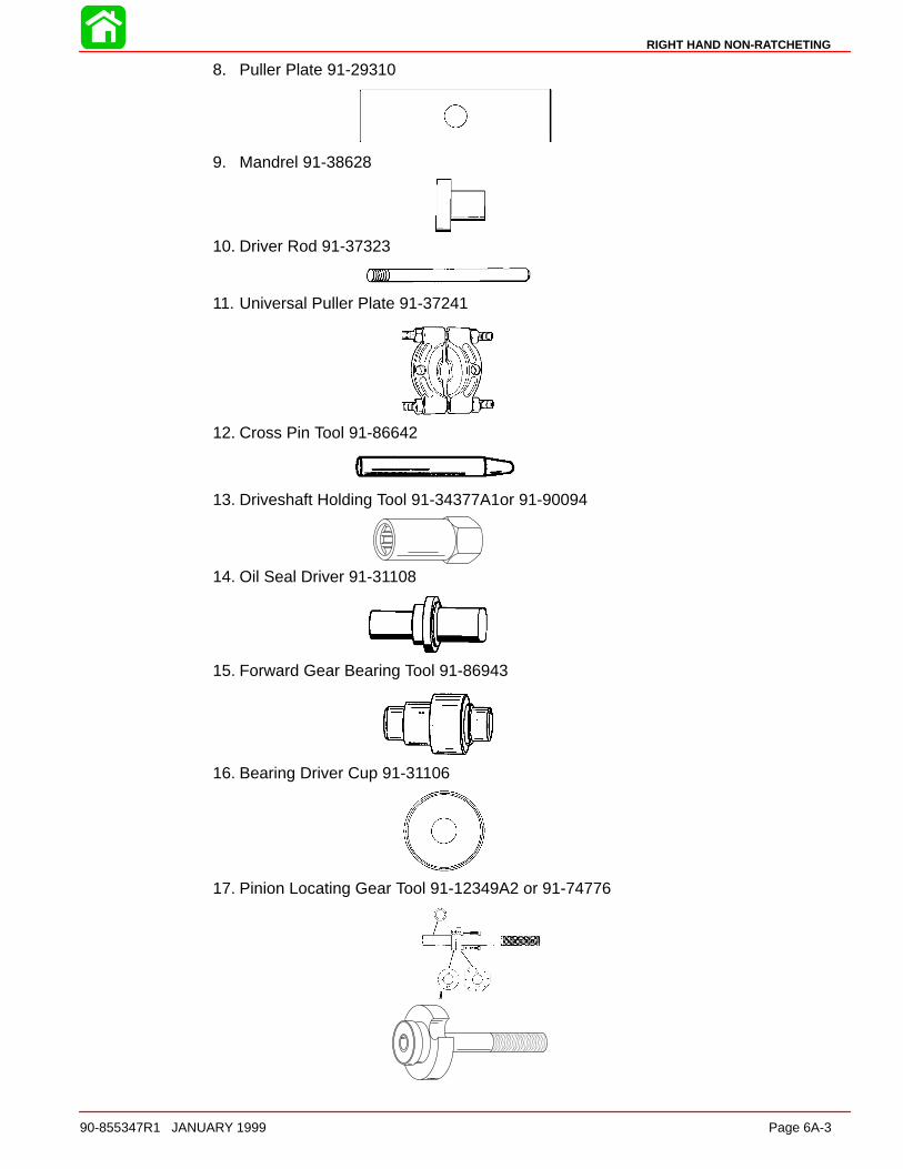
RIGHT HAND NON-RATCHETING
90-855347R1 JANUARY 1999 Page 6A-3
8. Puller Plate 91-29310
9. Mandrel 91-38628
10. Driver Rod 91-37323
11. Universal Puller Plate 91-37241
12. Cross Pin Tool 91-86642
13. Driveshaft Holding Tool 91-34377A1or 91-90094
14. Oil Seal Driver 91-31108
15. Forward Gear Bearing Tool 91-86943
16. Bearing Driver Cup 91-31106
17. Pinion Locating Gear Tool 91-12349A2 or 91-74776
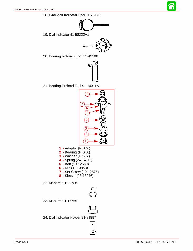
RIGHT HAND NON-RATCHETING
Page 6A-4 90-855347R1 JANUARY 1999
18. Backlash Indicator Rod 91-78473
19. Dial Indicator 91-58222A1
20. Bearing Retainer Tool 91-43506
21. Bearing Preload Tool 91-14311A1
1
2
3
4
56
7
8
1 - Adaptor (N.S.S.)2 - Bearing (N.S.S.)3 - Washer (N.S.S.)4 - Spring (24-14111)5 - Bolt (10-12580)6 - Nut (11-13953)7 - Set Screw (10-12575)8 - Sleeve (23-13946)
22. Mandrel 91-92788
23. Mandrel 91-15755
24. Dial Indicator Holder 91-89897

RIGHT HAND NON-RATCHETING
90-855347R1 JANUARY 1999 Page 6A-5
Notes:

RIGHT HAND NON-RATCHETING
Page 6A-6 90-855347R1 JANUARY 1999
Gear Housing (Drive Shaft)(Standard Rotation)
1
2
3
7
8
1012
13
1415
16
17
19
2223
24
2526
27
29
30
32
33
34
35
36
37
38
39
40
41
42
43
444546
4748
49
11
2010
45
28
31
23
95
95
7
95
95
95
98
33
109
795
95
7
95
19
95
109
995
Soap (Purchase Locally)23
4.75 IN./120.65MMTORPEDO DIA.
7 Loctite 271 (92-809820)
Perfect Seal (92-34227-1)19
Loctite 680 (92-809833)33
95 2-4-C With Teflon (92-825407A12)
GM Silicone Sealer (92-91600-1)109
4
5
6
18
21
19

RIGHT HAND NON-RATCHETING
90-855347R1 JANUARY 1999 Page 6A-7
Gear Housing (Drive Shaft)(Standard Rotation)
REF. TORQUEREF.NO. QTY. DESCRIPTION lb-in lb-ft Nm.
1 1 GEAR HOUSING (BLACK)(BASIC)2 1 CONNECTOR ASSEMBLY 50 5.53 2 DOWEL PIN
41 STUD (3-1/8 IN.) (LONG)
4 1 STUD (3-11/16 IN.) (X-LONG)5 2 STUD (2-1/16 IN.)6 1 STUD (3-3/8 IN.)7 2 STUD (3-1/8 IN.)8 1 FILLER BLOCK9 1 ROLLER BEARING10 2 ANODE11 1 SCREW (M6 x 40)12 1 NUT 60 7
131 PINION GEAR (1.87:1 - 15 TEETH)(150)(Part of 43-828174A2)
13 1 PINION GEAR (2:1 - 14 TEETH)(135)(Also part of 43-828176A2)14 1 WASHER15 1 NUT 75 10116 AR SHIM SET17 1 SCREW–drain (MAGNETIC) 60 718 1 SCREW–grease filler 60 719 2 WASHER20 1 STA-STRAP21 1 SHIFT SHAFT22 1 O-RING23 1 BUSHING ASSEMBLY 50 5.524 1 OIL SEAL25 1 WASHER–rubber
261 DRIVE SHAFT (LONG)
26 1 DRIVE SHAFT (X-LONG)27 1 ROLLER BEARING28 1 CUP29 1 RETAINER 100 13530 1 WATER PUMP BASE31 1 RETAINER32 1 GASKET33 1 O-RING34 1 OIL SEAL35 1 OIL SEAL36 1 GASKET–lower37 1 GASKET–upper38 1 FACE PLATE39 1 WATER PUMP BODY ASSEMBLY40 1 INSERT41 1 SEAL–rubber42 1 lMPELLER43 1 KEY44 1 SCREW (#14-8 x 2-1/4 IN.) 35 445 2 WASHER46 2 NUT 50 6847 1 WASHER48 1 NUT 50 6849 1 SLEEVE
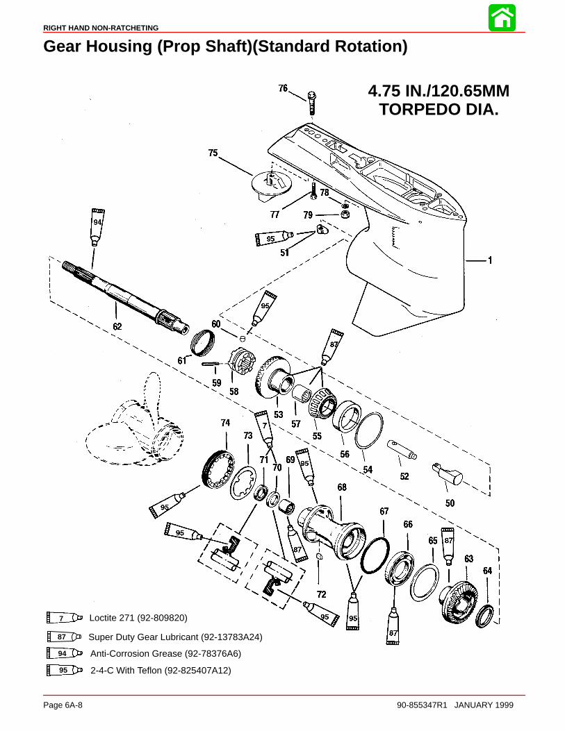
RIGHT HAND NON-RATCHETING
Page 6A-8 90-855347R1 JANUARY 1999
Gear Housing (Prop Shaft)(Standard Rotation)
87 Super Duty Gear Lubricant (92-13783A24)
4.75 IN./120.65MMTORPEDO DIA.
7 Loctite 271 (92-809820)
94 Anti-Corrosion Grease (92-78376A6)
95 2-4-C With Teflon (92-825407A12)
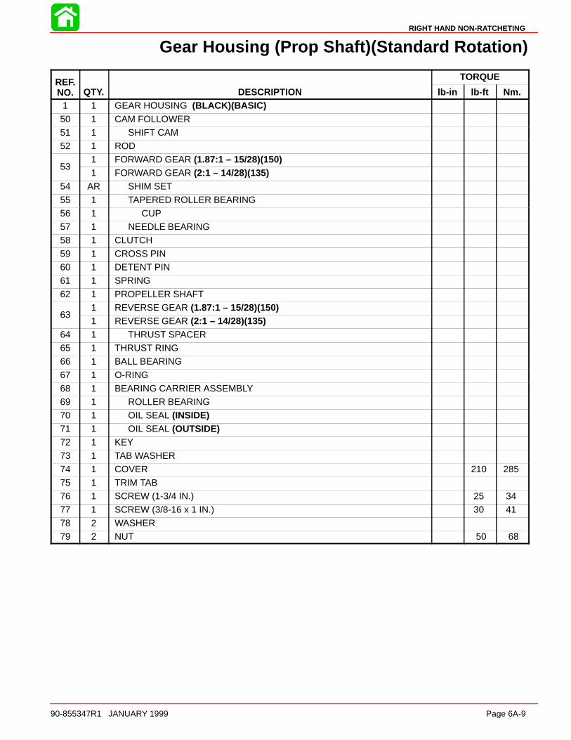
RIGHT HAND NON-RATCHETING
90-855347R1 JANUARY 1999 Page 6A-9
Gear Housing (Prop Shaft)(Standard Rotation)
REF. TORQUEREF.NO. QTY. DESCRIPTION lb-in lb-ft Nm.
1 1 GEAR HOUSING (BLACK)(BASIC)50 1 CAM FOLLOWER51 1 SHIFT CAM52 1 ROD
531 FORWARD GEAR (1.87:1 – 15/28)(150)
531 FORWARD GEAR (2:1 – 14/28)(135)
54 AR SHIM SET
55 1 TAPERED ROLLER BEARING56 1 CUP57 1 NEEDLE BEARING58 1 CLUTCH59 1 CROSS PIN60 1 DETENT PIN61 1 SPRING
62 1 PROPELLER SHAFT
631 REVERSE GEAR (1.87:1 – 15/28)(150)
631 REVERSE GEAR (2:1 – 14/28)(135)
64 1 THRUST SPACER65 1 THRUST RING66 1 BALL BEARING67 1 O-RING
68 1 BEARING CARRIER ASSEMBLY69 1 ROLLER BEARING70 1 OIL SEAL (INSIDE)71 1 OIL SEAL (OUTSIDE)72 1 KEY73 1 TAB WASHER74 1 COVER 210 285
75 1 TRIM TAB76 1 SCREW (1-3/4 IN.) 25 3477 1 SCREW (3/8-16 x 1 IN.) 30 4178 2 WASHER79 2 NUT 50 68

RIGHT HAND NON-RATCHETING
Page 6A-10 90-855347R1 JANUARY 1999
General Service Recommendations
There may be more than one way to “disassemble” or “reassemble” a particular part(s),therefore, it is recommended that the entire procedure be read prior to repair.
IMPORTANT: Read the following before attempting any repairs.
In many cases, disassembly of a sub-assembly may not be necessary until cleaning andinspection reveals that disassembly is required for replacement of one or more compo-nents.
Service procedure order in this section is a normal disassembly-reassembly sequence.It is suggested that the sequence be followed without deviation to assure proper repairs.When performing partial repairs, follow the instructions to the point where the desiredcomponent can be replaced, then proceed to “reassembly and installation” of that compo-nent in the reassembly part of this section. Use the “Table of Contents” (on back of sectiondivider) to find correct page number.
Threaded parts are right hand (RH), unless otherwise indicated.
When holding, pressing or driving is required, use soft metal vise jaw protectors or woodfor protection of parts. Use a suitable mandrel (one that will contact only the bearing race)when pressing or driving bearings.
Whenever compressed air is used to dry a part, be sure that no water is present in air line.
BEARINGS
Upon disassembly of gear housing, all bearings must be cleaned and inspected. Cleanbearings with solvent and dry with compressed air. Air should be directed at the bearingso that it passes thru the bearing. DO NOT spin bearing with compressed air, as this maycause bearing to score from lack of lubrication. After cleaning, lubricate bearings withQuicksilver Gear Lubricant. DO NOT lubricate tapered bearing cups until after inspection.
Inspect all bearings for roughness, catches and bearing race side wear. Work inner bear-ing race in-and-out, while holding outer race, to check for side wear.
When inspecting tapered bearings, determine condition of rollers and inner bearing raceby inspecting bearing cup for pitting, scoring, grooves, uneven wear, imbedded particlesand/or discoloration from overheating. Always replace tapered bearing and race as a set.
Roller bearing condition is determined by inspecting the bearing surface of the shaft thatthe roller bearing supports. Check shaft surface for pitting, scoring, grooving, imbeddedparticles, uneven wear and/or discoloration from overheating. The shaft and bearing mustbe replaced, if the conditions described are found.
SHIMS
Keep a record of all shim amounts and location during disassembly to aid in reassembly.Be sure to follow shimming instructions during reassembly, as gears must be installed tocorrect depth and have the correct amount of backlash to avoid noisy operation and pre-mature gear failure.
SEALS
As a normal procedure, all O-rings and oil seals SHOULD BE REPLACED without regardto appearance. To prevent leakage around oil seals, apply Loctite 271 to outer diameterof all metal case oil seals. When using Loctite on seals or threads, surfaces must be cleanand dry. To ease installation, apply Quicksilver 2-4-C w/Teflon Marine Lubricant on allO-rings. To prevent wear, apply Quicksilver 2-4-C w/Teflon Marine Lubricant on l.D. of oilseals.
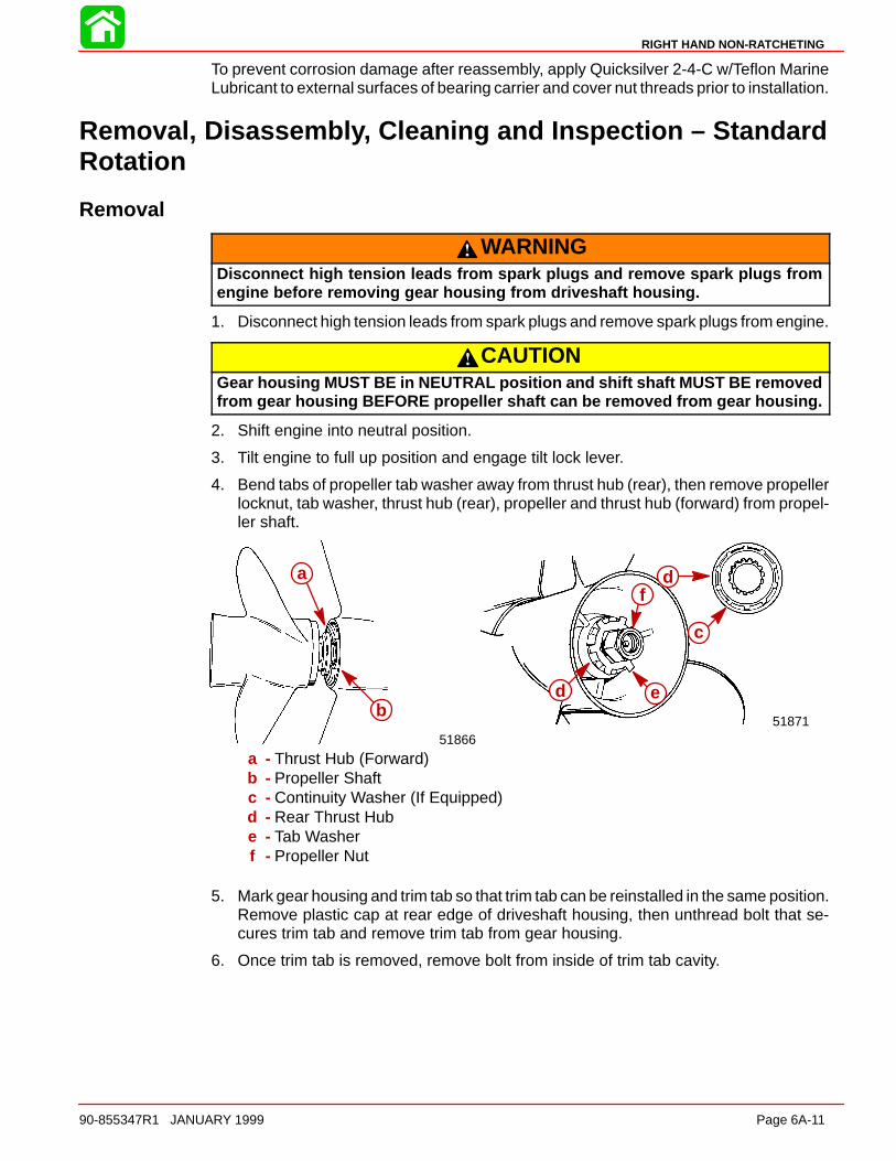
RIGHT HAND NON-RATCHETING
90-855347R1 JANUARY 1999 Page 6A-11
To prevent corrosion damage after reassembly, apply Quicksilver 2-4-C w/Teflon MarineLubricant to external surfaces of bearing carrier and cover nut threads prior to installation.
Removal, Disassembly, Cleaning and Inspection – StandardRotation
Removal
WARNINGDisconnect high tension leads from spark plugs and remove spark plugs fromengine before removing gear housing from driveshaft housing.
1. Disconnect high tension leads from spark plugs and remove spark plugs from engine.
CAUTIONGear housing MUST BE in NEUTRAL position and shift shaft MUST BE removedfrom gear housing BEFORE propeller shaft can be removed from gear housing.
2. Shift engine into neutral position.
3. Tilt engine to full up position and engage tilt lock lever.
4. Bend tabs of propeller tab washer away from thrust hub (rear), then remove propellerlocknut, tab washer, thrust hub (rear), propeller and thrust hub (forward) from propel-ler shaft.
5187151866
a
b
c
d
d e
f
a - Thrust Hub (Forward)b - Propeller Shaftc - Continuity Washer (If Equipped)d - Rear Thrust Hube - Tab Washerf - Propeller Nut
5. Mark gear housing and trim tab so that trim tab can be reinstalled in the same position.Remove plastic cap at rear edge of driveshaft housing, then unthread bolt that se-cures trim tab and remove trim tab from gear housing.
6. Once trim tab is removed, remove bolt from inside of trim tab cavity.
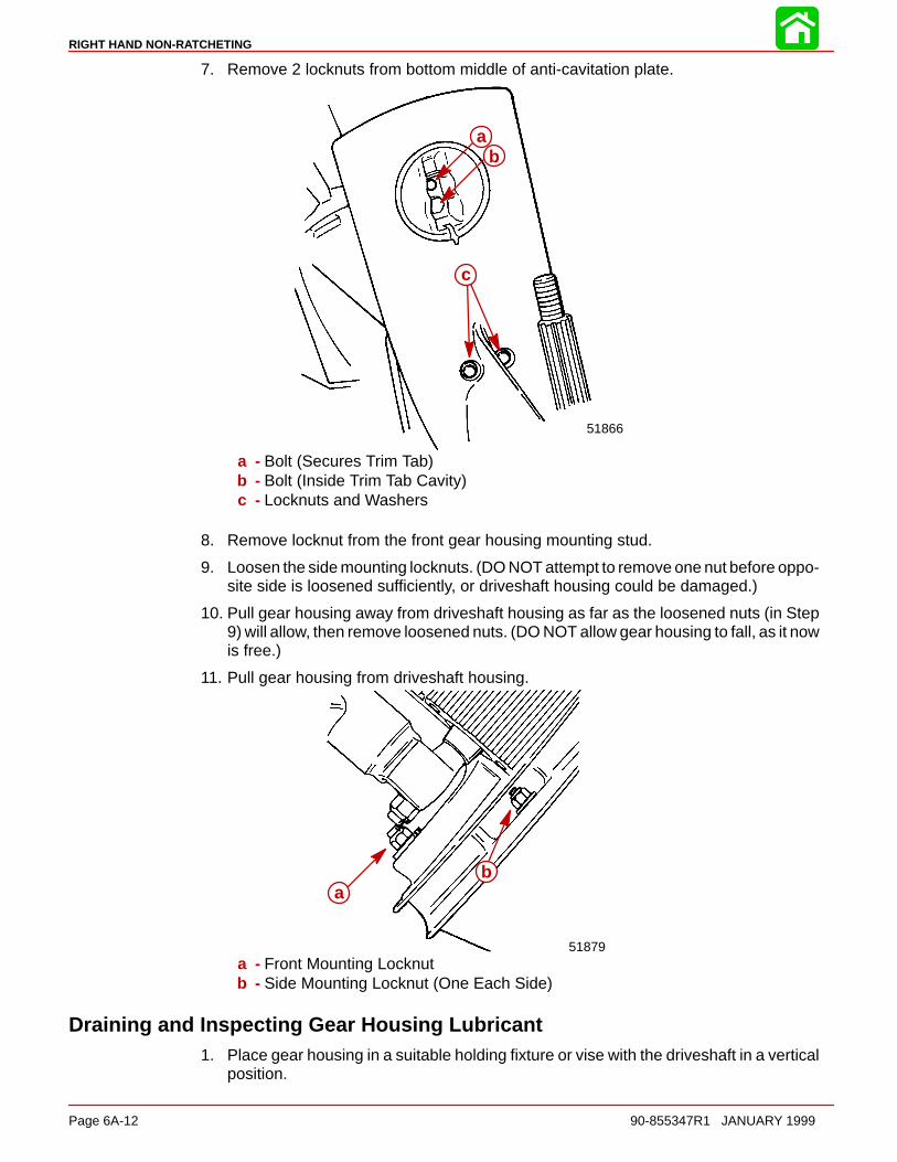
RIGHT HAND NON-RATCHETING
Page 6A-12 90-855347R1 JANUARY 1999
7. Remove 2 locknuts from bottom middle of anti-cavitation plate.
51866
ab
c
a - Bolt (Secures Trim Tab)b - Bolt (Inside Trim Tab Cavity)c - Locknuts and Washers
8. Remove locknut from the front gear housing mounting stud.
9. Loosen the side mounting locknuts. (DO NOT attempt to remove one nut before oppo-site side is loosened sufficiently, or driveshaft housing could be damaged.)
10. Pull gear housing away from driveshaft housing as far as the loosened nuts (in Step9) will allow, then remove loosened nuts. (DO NOT allow gear housing to fall, as it nowis free.)
11. Pull gear housing from driveshaft housing.
51879
ab
a - Front Mounting Locknutb - Side Mounting Locknut (One Each Side)
Draining and Inspecting Gear Housing Lubricant1. Place gear housing in a suitable holding fixture or vise with the driveshaft in a vertical
position.
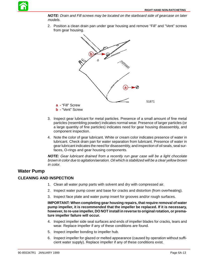
RIGHT HAND NON-RATCHETING
90-855347R1 JANUARY 1999 Page 6A-13
NOTE: Drain and Fill screws may be located on the starboard side of gearcase on latermodels.
2. Position a clean drain pan under gear housing and remove “Fill” and “Vent” screwsfrom gear housing.
51871
b
a
a - “Fill” Screwb - “Vent” Screw
3. Inspect gear lubricant for metal particles. Presence of a small amount of fine metalparticles (resembling powder) indicates normal wear. Presence of larger particles (ora large quantity of fine particles) indicates need for gear housing disassembly, andcomponent inspection.
4. Note the color of gear lubricant. White or cream color indicates presence of water inlubricant. Check drain pan for water separation from lubricant. Presence of water ingear lubricant indicates the need for disassembly, and inspection of oil seals, seal sur-faces, O-rings and gear housing components.
NOTE: Gear lubricant drained from a recently run gear case will be a light chocolatebrown in color due to agitation/aeration. Oil which is stabilized will be a clear yellow brownin color.
Water PumpCLEANING AND INSPECTION
1. Clean all water pump parts with solvent and dry with compressed air.
2. Inspect water pump cover and base for cracks and distortion (from overheating).
3. Inspect face plate and water pump insert for grooves and/or rough surfaces.
IMPORTANT: When completing gear housing repairs, that require removal of waterpump impeller, it is recommended that the impeller be replaced. If it is necessary,however, to re-use impeller, DO NOT install in reverse to original rotation, or prema-ture impeller failure will occur.
4. Inspect impeller side seal surfaces and ends of impeller blades for cracks, tears andwear. Replace impeller if any of these conditions are found.
5. Inspect impeller bonding to impeller hub.
6. Inspect impeller for glazed or melted appearance (caused by operation without suffi-cient water supply). Replace impeller if any of these conditions exist.
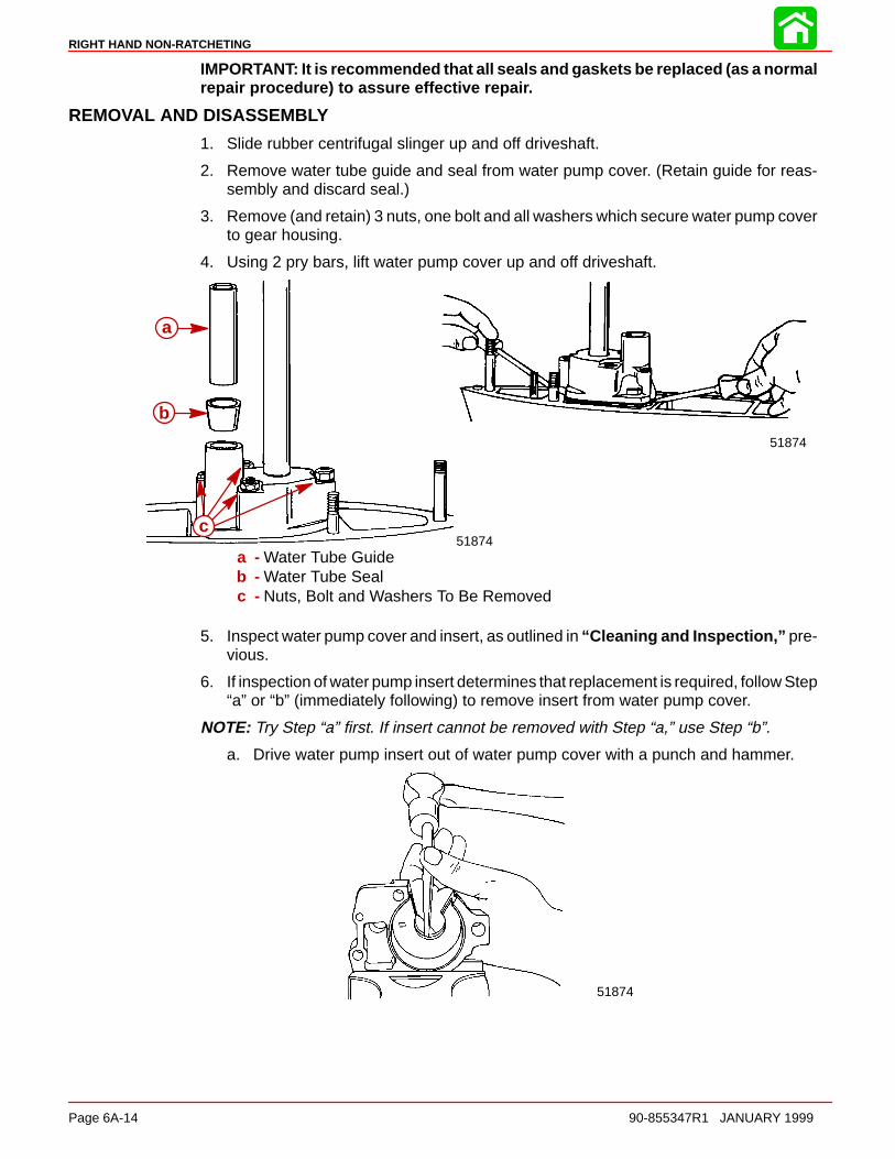
RIGHT HAND NON-RATCHETING
Page 6A-14 90-855347R1 JANUARY 1999
IMPORTANT: It is recommended that all seals and gaskets be replaced (as a normalrepair procedure) to assure effective repair.
REMOVAL AND DISASSEMBLY
1. Slide rubber centrifugal slinger up and off driveshaft.
2. Remove water tube guide and seal from water pump cover. (Retain guide for reas-sembly and discard seal.)
3. Remove (and retain) 3 nuts, one bolt and all washers which secure water pump coverto gear housing.
4. Using 2 pry bars, lift water pump cover up and off driveshaft.
51874
51874
a
b
c
a - Water Tube Guideb - Water Tube Sealc - Nuts, Bolt and Washers To Be Removed
5. Inspect water pump cover and insert, as outlined in “Cleaning and Inspection,” pre-vious.
6. If inspection of water pump insert determines that replacement is required, follow Step“a” or “b” (immediately following) to remove insert from water pump cover.
NOTE: Try Step “a” first. If insert cannot be removed with Step “a,” use Step “b”.
a. Drive water pump insert out of water pump cover with a punch and hammer.
51874

RIGHT HAND NON-RATCHETING
90-855347R1 JANUARY 1999 Page 6A-15
b. Drill two 3/16 in. (4.8mm) diameter holes thru the top of water pump cover (but notthru insert). Drive insert out of cover with a punch and hammer.
51873
a
a - Drill Two Holes at These Locations
7. Remove impeller from driveshaft. (It may be necessary to use a punch and hammerto drive impeller upward on driveshaft. In extreme cases, it may be necessary to splithub of impeller with a hammer and chisel.)
8. Once impeller is removed, remove impeller drive key from driveshaft.
9. Remove water pump face plate and both gaskets (one above and below face plate)from water pump base.
10. Using 2 pry bars, positioned and padded as shown, lift water pump base up and offdriveshaft.
51874a
a - Pads
11. Remove (and discard) O-ring from O-ring groove on water pump base.
12. Using a screwdriver, pry oil seals out of water pump base from gear housing side ofbase.

RIGHT HAND NON-RATCHETING
Page 6A-16 90-855347R1 JANUARY 1999
Bearing Carrier and Propeller Shaft Removal
CAUTIONGear housing MUST BE in NEUTRAL position, and shift shaft MUST BE removedfrom gear housing before propeller shaft can be removed from gear housing.
1. Place gear housing in a suitable holding fixture with propeller shaft in a horizontal posi-tion.
2. Use Shift Shaft Bushing Tool (91-31107) to unthread shift shaft bushing. (DO NOT re-move bushing from shift shaft at this time.)
IMPORTANT: Prior to removal of shift shaft from gear housing, recheck that gearhousing is in NEUTRAL position.
3. Bend cover nut lock tab out of cover nut recess.
51865
bc
51874
a
a - Shift Shaft Bushing Tool (91-31107)b - Punchc - Tab of Tab Washer
4. Remove gear housing cover nut with Cover Nut Tool (91-61069).
51866
a
a - Cover Nut Tool (91-61069)
5. After cover nut has been removed, remove lock tab washer from gear housing.
CAUTIONOnce bearing carrier is removed from gear housing, extreme care MUST BE takennot to apply any side force on propeller shaft. Side force on propeller shaft maybreak the neck of the clutch actuator rod.

RIGHT HAND NON-RATCHETING
90-855347R1 JANUARY 1999 Page 6A-17
6. Use long Puller Jaws (91-46086A1) and Puller Bolt (91-85716) to remove bearing car-rier. (Use propeller thrust hub to maintain outward pressure on puller jaws.)
NOTE: When bearing carrier is removed from gear housing, the bearing carrier alignmentkey will come out with it.
7. With gear housing in NEUTRAL, pull shift shaft out of gear housing. If necessary, usea pliers to pull shift shaft out of gear housing. If pliers are used to pull shift shaft out,wrap a strip of soft metal (aluminum) around splines before clamping pliers. DO NOTturn shaft (clockwise OR counterclockwise) while pulling shaft out. (For further infor-mation on shift shaft, see “Shift Shaft Cleaning/lnspection and Disassembly.”)
51867
51867
d
e
a
b
c
a - Long Puller Jaws (91-46086A1)b - Puller Bolt (91-85716)c - Thrust Hubd - Shift Shaft Bushinge - Shift Shaft
CAUTIONPropeller shaft, cam follower and shift cam, in most cases, will come out of gearhousing by simply pulling outward on propeller shaft. DO NOT FORCE shaft side-ways or ATTEMPT TO PULL with a slide hammer or any mechanical puller.
8. Remove propeller shaft, cam follower and shift cam by pulling shaft straight out of gearhousing. (DO NOT JERK propeller shaft.) If propeller shaft will not come out, proceedwith Step “a” or “b”, following:
a. Push propeller shaft back into place against the forward gear. Visually inspect lo-cation of shift cam by looking down shift shaft hole (illuminated with a flashlight).If splined hole in shift cam is visible, reinstall shift shaft and rotate shift shaft to neu-tral position. Remove shift shaft, then remove propeller shaft as instructed in Step8, immediately preceding.
b. Push propeller shaft back into place against forward gear. Slide bearing carrierback into gear housing (to support propeller shaft). Place gear housing on its leftside (viewed from rear) and strike upper leading end of gear housing with a rubbermallet. This will dislodge the shift cam from cam follower into a clearance pocketin left side of gear housing. Remove bearing carrier and pull propeller shaft outof gear housing.

RIGHT HAND NON-RATCHETING
Page 6A-18 90-855347R1 JANUARY 1999
NOTE: If Step 8-b was used to remove propeller shaft, the shift cam can be retrieved afterremoval of forward gear.
Shift ShaftCLEANING AND INSPECTION
1. Clean shift shaft and bushing with solvent and dry with compressed air.
2. Check shift shaft splines on both ends for wear and/or corrosion damage.
3. Inspect shift shaft for groove(s) at shift shaft bushing seal surface.
4. Inspect shift shaft bushing for corrosion damage.
5. Inspect shift shaft bushing oil seal for wear and/or cuts.
NOTE: Oil seal in shift shaft bushing should be replaced as a normal repair procedure.
DISASSEMBLY
1. Remove (and discard) shift shaft bushing oil seal by prying it out or driving it out witha punch and hammer.
CLEANING/INSPECTION - BEARING CARRIER
IMPORTANT: It is recommended that all seals and O-rings be replaced (as a normalrepair procedure) to assure effective repair.
1. Clean bearing carrier with solvent and dry with compressed air.
CAUTIONDO NOT spin bearings dry with compressed air, as this could cause bearing toscore.
2. Bearing carrier propeller shaft needle bearing condition is determined by propellershaft bearing surface condition. (See “Propeller Shaft Inspection.”)
3. Inspect reverse gear to pinion gear wear pattern (should be even and smooth). If not,replace reverse gear and pinion gear.
4. Check clutch jaws on reverse gear for damage. Replace reverse gear, if damage isfound on clutch jaws.
5. Apply light oil to reverse gear bearing. Rotate reverse gear bearing while checkingbearing for rough spots and/or catches. Push in and pull out on reverse gear to checkfor bearing side wear. Replace bearing if any of the listed conditions exist.
DISASSEMBLY - BEARING CARRIER
1. Remove and discard O-ring from between bearing carrier and thrust washer.
2. If inspection of reverse gear or reverse gear bearing determines that replacement ofgear or bearing is required, remove gear and bearing as follows:
a. Position bearing carrier in a soft jaw vise.
b. Use Slide Hammer (91-34569A1) and remove reverse gear.
51868

RIGHT HAND NON-RATCHETING
90-855347R1 JANUARY 1999 Page 6A-19
c. If reverse gear bearing remains attached to reverse gear, install Universal PullerPlate (91-37241) and position puller plate, gear and bearing on a press with gearside down. Use a suitable mandrel and press gear out of bearing.
51874a
b
a - Universal Puller Plateb - Mandrel
d. If reverse gear bearing has remained in bearing carrier, use slide hammer to re-move bearing in the same methods as was used to remove reverse gear (Step“b”).
3. Propeller shaft oil seals can be removed by (a) using a pry bar, or (b) pressing sealsout when propeller shaft needle bearing is pressed out of bearing carrier.
4. If inspection of propeller shaft needle bearing determines that replacement of bearingis required, use Universal Bearing Removal and Installation Tool (91-31229A1) topress bearing and seals out of bearing carrier.
NOTE: Reverse gear must be removed from bearing carrier before propeller shaft needlebearing can be removed.
51871
b
c
d
51868
a
a - Pry Barb - Propeller Shaft Needle Bearingc - Mandreld - Oil Seals
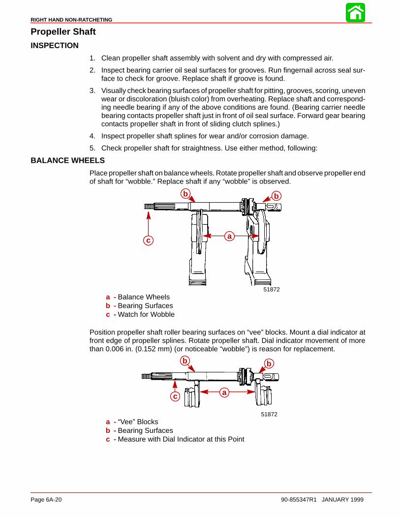
RIGHT HAND NON-RATCHETING
Page 6A-20 90-855347R1 JANUARY 1999
Propeller ShaftINSPECTION
1. Clean propeller shaft assembly with solvent and dry with compressed air.
2. Inspect bearing carrier oil seal surfaces for grooves. Run fingernail across seal sur-face to check for groove. Replace shaft if groove is found.
3. Visually check bearing surfaces of propeller shaft for pitting, grooves, scoring, unevenwear or discoloration (bluish color) from overheating. Replace shaft and correspond-ing needle bearing if any of the above conditions are found. (Bearing carrier needlebearing contacts propeller shaft just in front of oil seal surface. Forward gear bearingcontacts propeller shaft in front of sliding clutch splines.)
4. Inspect propeller shaft splines for wear and/or corrosion damage.
5. Check propeller shaft for straightness. Use either method, following:
BALANCE WHEELS
Place propeller shaft on balance wheels. Rotate propeller shaft and observe propeller endof shaft for “wobble.” Replace shaft if any “wobble” is observed.
51872
a
b b
c
a - Balance Wheelsb - Bearing Surfacesc - Watch for Wobble
Position propeller shaft roller bearing surfaces on “vee” blocks. Mount a dial indicator atfront edge of propeller splines. Rotate propeller shaft. Dial indicator movement of morethan 0.006 in. (0.152 mm) (or noticeable “wobble”) is reason for replacement.
51872
a
bb
c
a - “Vee” Blocksb - Bearing Surfacesc - Measure with Dial Indicator at this Point
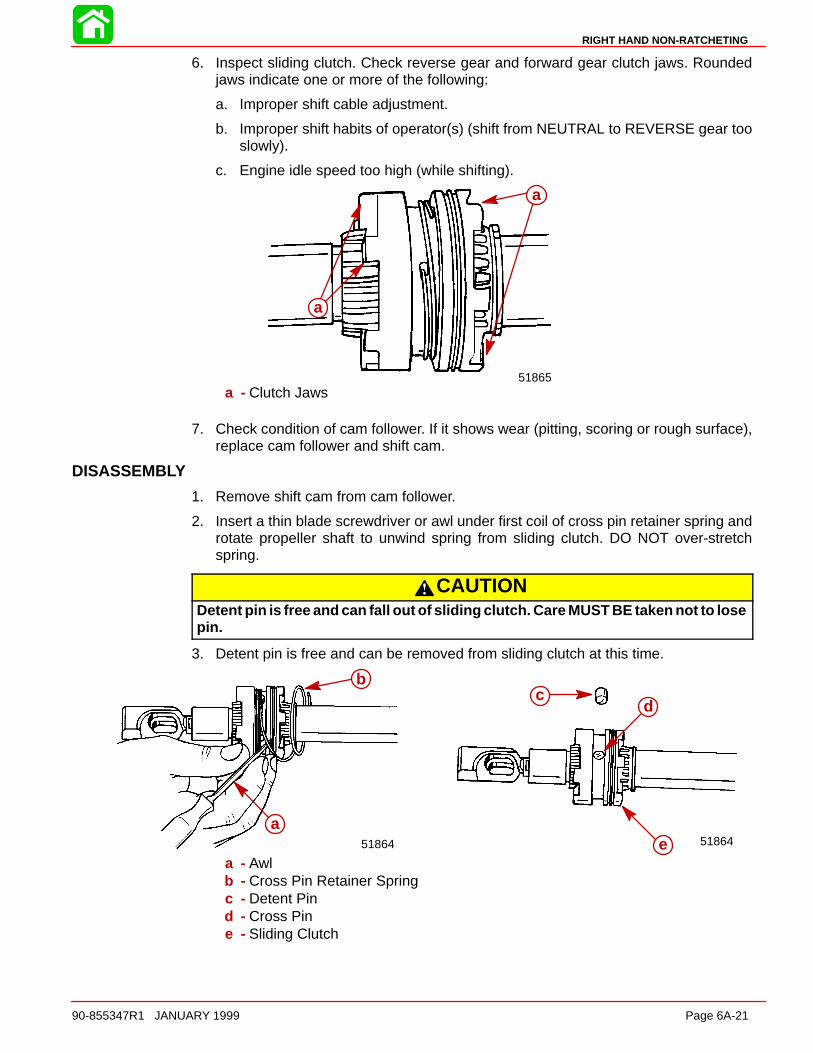
RIGHT HAND NON-RATCHETING
90-855347R1 JANUARY 1999 Page 6A-21
6. Inspect sliding clutch. Check reverse gear and forward gear clutch jaws. Roundedjaws indicate one or more of the following:
a. Improper shift cable adjustment.
b. Improper shift habits of operator(s) (shift from NEUTRAL to REVERSE gear tooslowly).
c. Engine idle speed too high (while shifting).
51865
a
a
a - Clutch Jaws
7. Check condition of cam follower. If it shows wear (pitting, scoring or rough surface),replace cam follower and shift cam.
DISASSEMBLY
1. Remove shift cam from cam follower.
2. Insert a thin blade screwdriver or awl under first coil of cross pin retainer spring androtate propeller shaft to unwind spring from sliding clutch. DO NOT over-stretchspring.
CAUTIONDetent pin is free and can fall out of sliding clutch. Care MUST BE taken not to losepin.
3. Detent pin is free and can be removed from sliding clutch at this time.
51864
cd
e51864
a
b
a - Awlb - Cross Pin Retainer Springc - Detent Pind - Cross Pine - Sliding Clutch

RIGHT HAND NON-RATCHETING
Page 6A-22 90-855347R1 JANUARY 1999
4. Push cross pin out of sliding clutch and propeller shaft with Cross Pin Tool (91-86642).
5. Pull sliding clutch off propeller shaft.
6. Pull cam follower and clutch actuator rod out of propeller shaft. DO NOT force camfollower up-or-down or side-to-side when pulling from propeller shaft.
51864
51864
c d e
a
b
a - Cross Pin Tool (91-86642)b - Cross Pinc - Cam Followerd - Clutch Actuator Rode - Propeller Shaft
7. Once cam follower and clutch actuator rod are removed from propeller shaft, lift rodout of cam follower.
Clutch Actuator RodCLEANING AND INSPECTION
1. Clean clutch actuator rod in solvent and dry with compressed air.
2. Inspect actuator components for wear or damage. Replace components as required.
Pinion Gear and DriveshaftREMOVAL
1. Remove bearing retainer using Bearing Retainer Tool (91-43506).
51865a
b
a - Bearing Retainerb - Bearing Retainer Tool (91-43506)
2. Place Driveshaft Holding Tool (91-34377A1) over driveshaft splines.
3. Use a socket and flex handle to hold pinion nut. (Pad area of gear housing where flexhandle will make contact to prevent damage to gear housing.)
4. Use a socket and flex handle on Driveshaft Holding Tool to loosen pinion nut. Removepinion nut and Driveshaft Holding Tool.
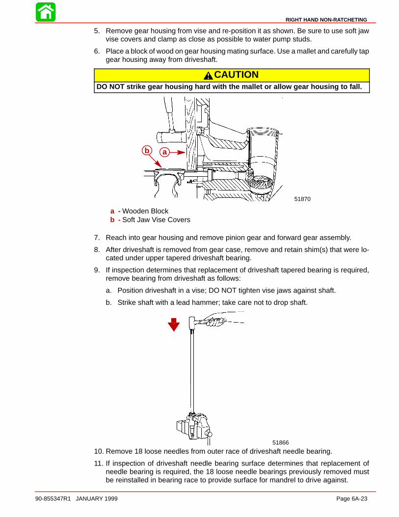
RIGHT HAND NON-RATCHETING
90-855347R1 JANUARY 1999 Page 6A-23
5. Remove gear housing from vise and re-position it as shown. Be sure to use soft jawvise covers and clamp as close as possible to water pump studs.
6. Place a block of wood on gear housing mating surface. Use a mallet and carefully tapgear housing away from driveshaft.
CAUTIONDO NOT strike gear housing hard with the mallet or allow gear housing to fall.
51870
ab
a - Wooden Blockb - Soft Jaw Vise Covers
7. Reach into gear housing and remove pinion gear and forward gear assembly.
8. After driveshaft is removed from gear case, remove and retain shim(s) that were lo-cated under upper tapered driveshaft bearing.
9. If inspection determines that replacement of driveshaft tapered bearing is required,remove bearing from driveshaft as follows:
a. Position driveshaft in a vise; DO NOT tighten vise jaws against shaft.
b. Strike shaft with a lead hammer; take care not to drop shaft.
51866
10. Remove 18 loose needles from outer race of driveshaft needle bearing.
11. If inspection of driveshaft needle bearing surface determines that replacement ofneedle bearing is required, the 18 loose needle bearings previously removed mustbe reinstalled in bearing race to provide surface for mandrel to drive against.
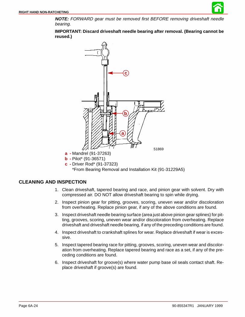
RIGHT HAND NON-RATCHETING
Page 6A-24 90-855347R1 JANUARY 1999
NOTE: FORWARD gear must be removed first BEFORE removing driveshaft needlebearing.
IMPORTANT: Discard driveshaft needle bearing after removal. (Bearing cannot bereused.)
51869
a
b
c
a - Mandrel (91-37263)b - Pilot* (91-36571)c - Driver Rod* (91-37323)
*From Bearing Removal and Installation Kit (91-31229A5)
CLEANING AND INSPECTION
1. Clean driveshaft, tapered bearing and race, and pinion gear with solvent. Dry withcompressed air. DO NOT allow driveshaft bearing to spin while drying.
2. Inspect pinion gear for pitting, grooves, scoring, uneven wear and/or discolorationfrom overheating. Replace pinion gear, if any of the above conditions are found.
3. Inspect driveshaft needle bearing surface (area just above pinion gear splines) for pit-ting, grooves, scoring, uneven wear and/or discoloration from overheating. Replacedriveshaft and driveshaft needle bearing, if any of the preceding conditions are found.
4. Inspect driveshaft to crankshaft splines for wear. Replace driveshaft if wear is exces-sive.
5. Inspect tapered bearing race for pitting, grooves, scoring, uneven wear and discolor-ation from overheating. Replace tapered bearing and race as a set, if any of the pre-ceding conditions are found.
6. Inspect driveshaft for groove(s) where water pump base oil seals contact shaft. Re-place driveshaft if groove(s) are found.

RIGHT HAND NON-RATCHETING
90-855347R1 JANUARY 1999 Page 6A-25
Forward GearREMOVAL AND DISASSEMBLY
NOTE: Forward gear can only be removed from gear housing after driveshaft and piniongear have been removed.
1. Reach into gear housing and lift out forward gear.
IMPORTANT: DO NOT remove tapered bearing or needle bearings from forwardgear, unless replacement of bearings is required. (Bearings cannot be reused afterthey have been removed.)
2. If inspection determines that replacement of forward gear tapered bearing is required,remove bearing from gear and bearing race from gear housing (tapered bearing andrace MUST BE replaced as a set), as follows:
a. Install Universal Puller Plate (91-37241) between forward gear and tapered bear-ing.
b. Place forward gear, bearing and puller plate on a press and press gear out of bear-ing with a suitable mandrel.
c. Use Slide Hammer (91-34569A1) to remove forward gear tapered bearing race.
5186551870
c
d
a
b
a - Universal Puller Plateb - Mandrelc - Slide Hammerd - Tapered Bearing Race
d. After forward gear tapered bearing race is removed from gear housing, lift out andretain shims which were behind bearing race.
3. If inspection determines that replacement of propeller shaft needle bearings in for-ward gear is required, remove bearing from gear as follows:
a. Clamp forward gear in a soft jaw vise securely.
b. From toothed-side of gear, drive propeller shaft needle bearings out of gear witha punch and hammer.

RIGHT HAND NON-RATCHETING
Page 6A-26 90-855347R1 JANUARY 1999
CLEANING AND INSPECTION
CAUTIONDO NOT spin bearings dry with compressed air, as this could cause bearing toscore.
1. Clean forward gear and bearings with solvent and dry with compressed air.
2. Inspect gear teeth for pitting, grooves, scoring, uneven wear and for discoloration(from overheating). Replace gear if any of these conditions are found.
3. Check clutch jaws on forward gear for damage. Replace forward gear if damage isfound.
4. Inspect tapered bearing race for pitting, grooves, scoring, uneven wear and discolor-ation (from overheating). Replace tapered bearing (on forward gear) and race if anyof these conditions are found. (Always replace tapered bearing and race as a set.)
5. To determine condition of propeller shaft needle bearings (in forward gear), inspectpropeller shaft forward gear needle bearing surface as outlined in “Propeller ShaftInspection.”
Gear HousingCLEANING AND INSPECTION
1. Clean gear housing with solvent and dry with compressed air.
2. Check gear housing carefully for impact damage.
3. Check for loose fitting bearing cups and needle bearings.
4. Inspect bearing carrier cover nut retainer threads in gear housing for corrosion dam-age and/or stripped threads.
Reassembly and Installation Standard Rotation
Driveshaft Needle BearingREASSEMBLY/INSTALLATION
CAUTIONIf driveshaft needle bearing failure has occurred, and original bearing race hasturned in the gear housing, gear housing MUST be replaced. Loose fitting needlebearing will move out of position and cause repeated failures.
1. Apply a thin coat of Quicksilver 2-4-C w/Teflon Lubricant to driveshaft needle bearingbore in gear housing.
2. By way of propeller shaft cavity, place needle bearing in driveshaft bore with num-bered side of bearing facing up driveshaft bore.
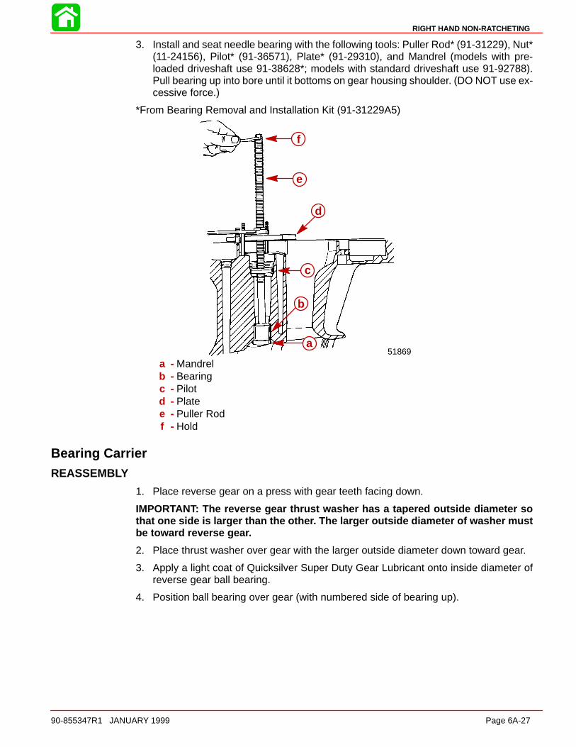
RIGHT HAND NON-RATCHETING
90-855347R1 JANUARY 1999 Page 6A-27
3. Install and seat needle bearing with the following tools: Puller Rod* (91-31229), Nut*(11-24156), Pilot* (91-36571), Plate* (91-29310), and Mandrel (models with pre-loaded driveshaft use 91-38628*; models with standard driveshaft use 91-92788).Pull bearing up into bore until it bottoms on gear housing shoulder. (DO NOT use ex-cessive force.)
*From Bearing Removal and Installation Kit (91-31229A5)
51869a
b
c
d
e
f
a - Mandrelb - Bearingc - Pilotd - Platee - Puller Rodf - Hold
Bearing CarrierREASSEMBLY
1. Place reverse gear on a press with gear teeth facing down.
IMPORTANT: The reverse gear thrust washer has a tapered outside diameter sothat one side is larger than the other. The larger outside diameter of washer mustbe toward reverse gear.
2. Place thrust washer over gear with the larger outside diameter down toward gear.
3. Apply a light coat of Quicksilver Super Duty Gear Lubricant onto inside diameter ofreverse gear ball bearing.
4. Position ball bearing over gear (with numbered side of bearing up).
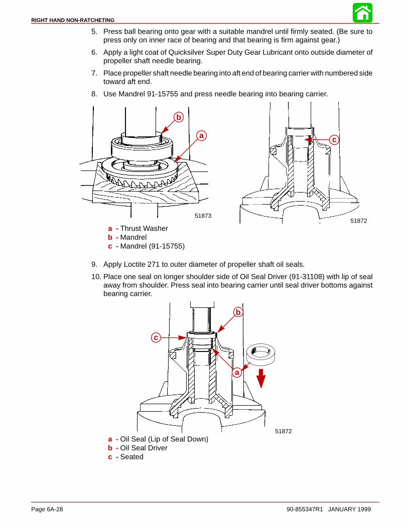
RIGHT HAND NON-RATCHETING
Page 6A-28 90-855347R1 JANUARY 1999
5. Press ball bearing onto gear with a suitable mandrel until firmly seated. (Be sure topress only on inner race of bearing and that bearing is firm against gear.)
6. Apply a light coat of Quicksilver Super Duty Gear Lubricant onto outside diameter ofpropeller shaft needle bearing.
7. Place propeller shaft needle bearing into aft end of bearing carrier with numbered sidetoward aft end.
8. Use Mandrel 91-15755 and press needle bearing into bearing carrier.
5187251873
a
b
c
a - Thrust Washerb - Mandrelc - Mandrel (91-15755)
9. Apply Loctite 271 to outer diameter of propeller shaft oil seals.
10. Place one seal on longer shoulder side of Oil Seal Driver (91-31108) with lip of sealaway from shoulder. Press seal into bearing carrier until seal driver bottoms againstbearing carrier.
51872
a
b
c
a - Oil Seal (Lip of Seal Down)b - Oil Seal Driverc - Seated
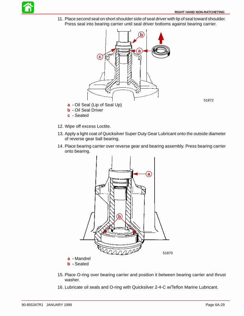
RIGHT HAND NON-RATCHETING
90-855347R1 JANUARY 1999 Page 6A-29
11. Place second seal on short shoulder side of seal driver with lip of seal toward shoulder.Press seal into bearing carrier until seal driver bottoms against bearing carrier.
51872
a
b
c
a - Oil Seal (Lip of Seal Up)b - Oil Seal Driverc - Seated
12. Wipe off excess Loctite.
13. Apply a light coat of Quicksilver Super Duty Gear Lubricant onto the outside diameterof reverse gear ball bearing.
14. Place bearing carrier over reverse gear and bearing assembly. Press bearing carrieronto bearing.
51870
a
b
a - Mandrelb - Seated
15. Place O-ring over bearing carrier and position it between bearing carrier and thrustwasher.
16. Lubricate oil seals and O-ring with Quicksilver 2-4-C w/Teflon Marine Lubricant.
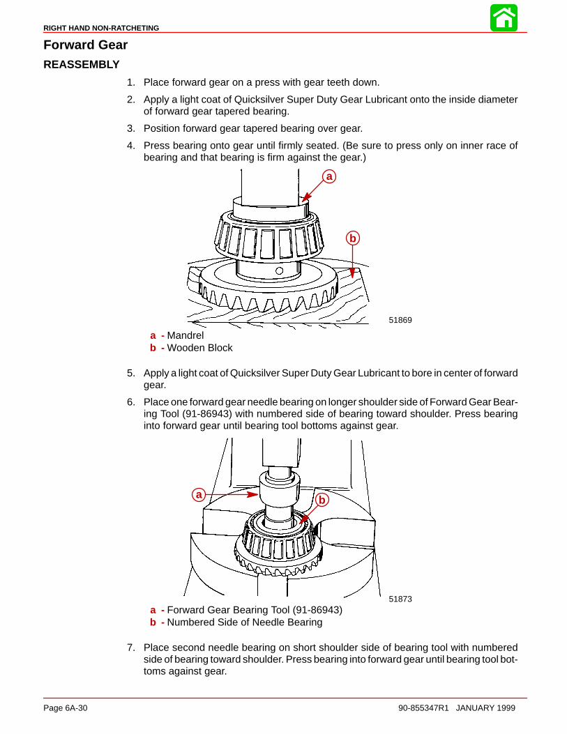
RIGHT HAND NON-RATCHETING
Page 6A-30 90-855347R1 JANUARY 1999
Forward GearREASSEMBLY
1. Place forward gear on a press with gear teeth down.
2. Apply a light coat of Quicksilver Super Duty Gear Lubricant onto the inside diameterof forward gear tapered bearing.
3. Position forward gear tapered bearing over gear.
4. Press bearing onto gear until firmly seated. (Be sure to press only on inner race ofbearing and that bearing is firm against the gear.)
51869
a
b
a - Mandrelb - Wooden Block
5. Apply a light coat of Quicksilver Super Duty Gear Lubricant to bore in center of forwardgear.
6. Place one forward gear needle bearing on longer shoulder side of Forward Gear Bear-ing Tool (91-86943) with numbered side of bearing toward shoulder. Press bearinginto forward gear until bearing tool bottoms against gear.
51873
a b
a - Forward Gear Bearing Tool (91-86943)b - Numbered Side of Needle Bearing
7. Place second needle bearing on short shoulder side of bearing tool with numberedside of bearing toward shoulder. Press bearing into forward gear until bearing tool bot-toms against gear.
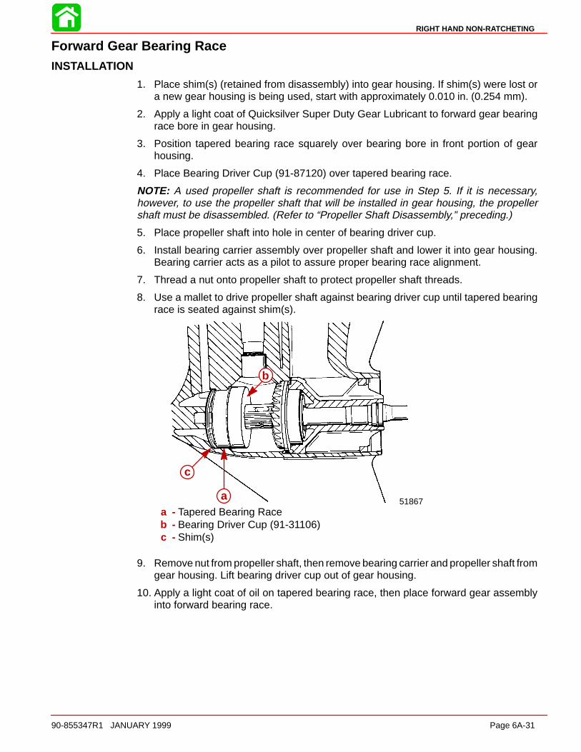
RIGHT HAND NON-RATCHETING
90-855347R1 JANUARY 1999 Page 6A-31
Forward Gear Bearing RaceINSTALLATION
1. Place shim(s) (retained from disassembly) into gear housing. If shim(s) were lost ora new gear housing is being used, start with approximately 0.010 in. (0.254 mm).
2. Apply a light coat of Quicksilver Super Duty Gear Lubricant to forward gear bearingrace bore in gear housing.
3. Position tapered bearing race squarely over bearing bore in front portion of gearhousing.
4. Place Bearing Driver Cup (91-87120) over tapered bearing race.
NOTE: A used propeller shaft is recommended for use in Step 5. If it is necessary,however, to use the propeller shaft that will be installed in gear housing, the propellershaft must be disassembled. (Refer to “Propeller Shaft Disassembly,” preceding.)
5. Place propeller shaft into hole in center of bearing driver cup.
6. Install bearing carrier assembly over propeller shaft and lower it into gear housing.Bearing carrier acts as a pilot to assure proper bearing race alignment.
7. Thread a nut onto propeller shaft to protect propeller shaft threads.
8. Use a mallet to drive propeller shaft against bearing driver cup until tapered bearingrace is seated against shim(s).
51867a
b
c
a - Tapered Bearing Raceb - Bearing Driver Cup (91-31106)c - Shim(s)
9. Remove nut from propeller shaft, then remove bearing carrier and propeller shaft fromgear housing. Lift bearing driver cup out of gear housing.
10. Apply a light coat of oil on tapered bearing race, then place forward gear assemblyinto forward bearing race.
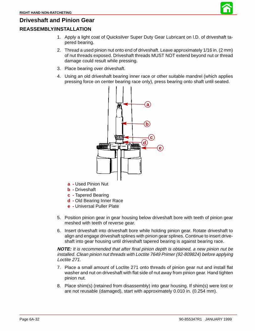
RIGHT HAND NON-RATCHETING
Page 6A-32 90-855347R1 JANUARY 1999
Driveshaft and Pinion GearREASSEMBLY/INSTALLATION
1. Apply a light coat of Quicksilver Super Duty Gear Lubricant on l.D. of driveshaft ta-pered bearing.
2. Thread a used pinion nut onto end of driveshaft. Leave approximately 1/16 in. (2 mm)of nut threads exposed. Driveshaft threads MUST NOT extend beyond nut or threaddamage could result while pressing.
3. Place bearing over driveshaft.
4. Using an old driveshaft bearing inner race or other suitable mandrel (which appliespressing force on center bearing race only), press bearing onto shaft until seated.
a
b
cd
e
a - Used Pinion Nutb - Driveshaftc - Tapered Bearingd - Old Bearing Inner Racee - Universal Puller Plate
5. Position pinion gear in gear housing below driveshaft bore with teeth of pinion gearmeshed with teeth of reverse gear.
6. Insert driveshaft into driveshaft bore while holding pinion gear. Rotate driveshaft toalign and engage driveshaft splines with pinion gear splines. Continue to insert drive-shaft into gear housing until driveshaft tapered bearing is against bearing race.
NOTE: It is recommended that after final pinion depth is obtained, a new pinion nut beinstalled. Clean pinion nut threads with Loctite 7649 Primer (92-809824) before applyingLoctite 271.
7. Place a small amount of Loctite 271 onto threads of pinion gear nut and install flatwasher and nut on driveshaft with flat side of nut away from pinion gear. Hand tightenpinion nut.
8. Place shim(s) (retained from disassembly) into gear housing. If shim(s) were lost orare not reusable (damaged), start with approximately 0.010 in. (0.254 mm).
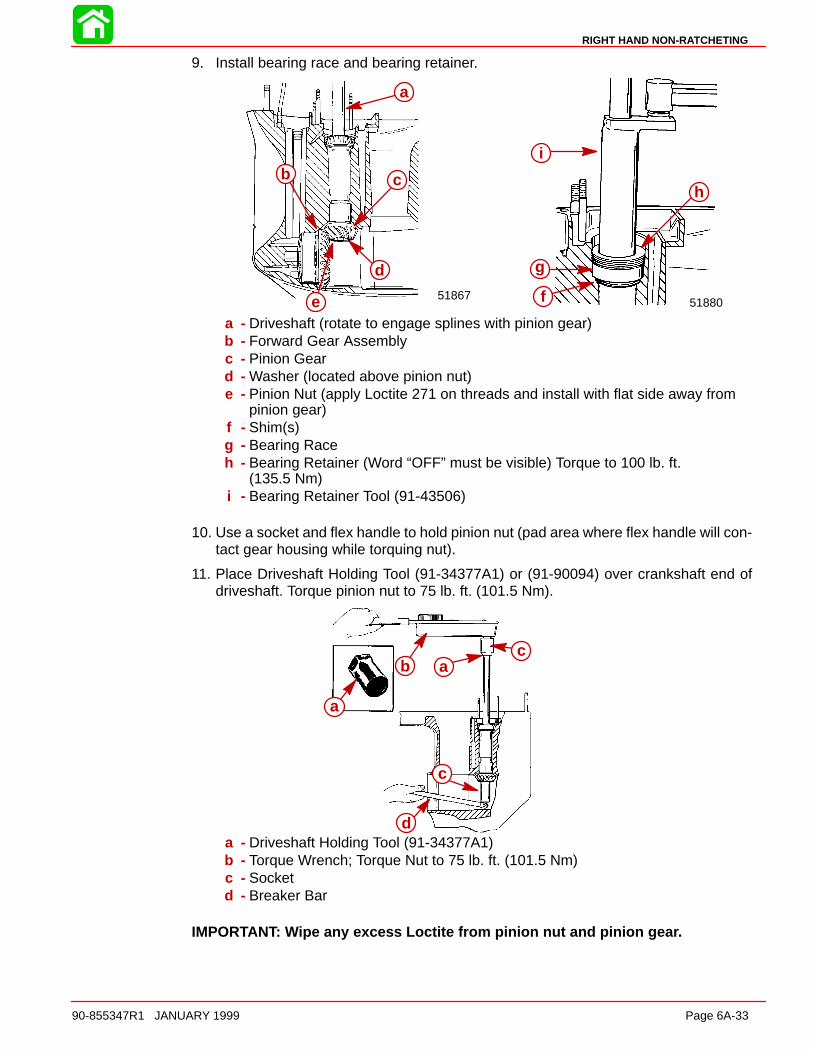
RIGHT HAND NON-RATCHETING
90-855347R1 JANUARY 1999 Page 6A-33
9. Install bearing race and bearing retainer.
5188051867 f
g
h
i
a
b c
d
ea - Driveshaft (rotate to engage splines with pinion gear)b - Forward Gear Assemblyc - Pinion Geard - Washer (located above pinion nut)e - Pinion Nut (apply Loctite 271 on threads and install with flat side away from
pinion gear)f - Shim(s)g - Bearing Raceh - Bearing Retainer (Word “OFF” must be visible) Torque to 100 lb. ft.
(135.5 Nm)i - Bearing Retainer Tool (91-43506)
10. Use a socket and flex handle to hold pinion nut (pad area where flex handle will con-tact gear housing while torquing nut).
11. Place Driveshaft Holding Tool (91-34377A1) or (91-90094) over crankshaft end ofdriveshaft. Torque pinion nut to 75 lb. ft. (101.5 Nm).
a
b ac
c
da - Driveshaft Holding Tool (91-34377A1)b - Torque Wrench; Torque Nut to 75 lb. ft. (101.5 Nm)c - Socketd - Breaker Bar
IMPORTANT: Wipe any excess Loctite from pinion nut and pinion gear.

RIGHT HAND NON-RATCHETING
Page 6A-34 90-855347R1 JANUARY 1999
Pinion Gear Depth/Forward Gear Backlash/Reverse Gear BacklashDETERMINING PINION GEAR DEPTH
NOTE: Read entire procedure before attempting any change in shim thickness.
IMPORTANT: Forward gear assembly must be installed in gear housing whenchecking pinion gear depth or an inaccurate measurement will be obtained.
1. Clean the gear housing bearing carrier shoulder.
2. Install Bearing Preload Tool (91-14311A1) over driveshaft in sequence shown.
NOTE: Bearing Preload Tool (91-44307A1) may also be used. Follow instructions pro-vided with tool for proper installation.
a
b
c
d
e
f
g
h
g
a - Adaptorb - Bearingc - Washerd - Springe - Nut; thread nut all the way onto boltf - Boltg - Set Screwh - Sleeve; Holes in sleeve must align with set screw
3. Align adaptor on driveshaft bearing pocket ledge.
4. With tool installed over driveshaft, tighten both set screws securely, making certainto align sleeve holes to allow set screws to pass thru.
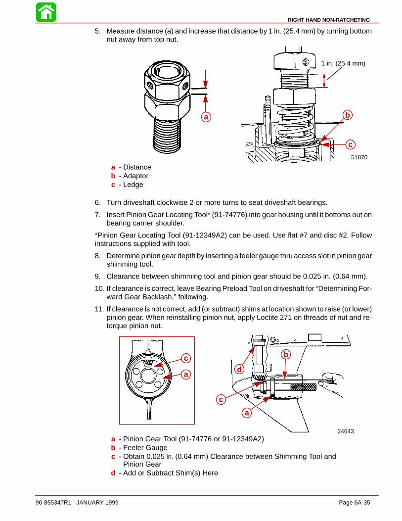
RIGHT HAND NON-RATCHETING
90-855347R1 JANUARY 1999 Page 6A-35
5. Measure distance (a) and increase that distance by 1 in. (25.4 mm) by turning bottomnut away from top nut.
1 in. (25.4 mm)
51870
b
c
a
a - Distanceb - Adaptorc - Ledge
6. Turn driveshaft clockwise 2 or more turns to seat driveshaft bearings.
7. Insert Pinion Gear Locating Tool* (91-74776) into gear housing until it bottoms out onbearing carrier shoulder.
*Pinion Gear Locating Tool (91-12349A2) can be used. Use flat #7 and disc #2. Followinstructions supplied with tool.
8. Determine pinion gear depth by inserting a feeler gauge thru access slot in pinion gearshimming tool.
9. Clearance between shimming tool and pinion gear should be 0.025 in. (0.64 mm).
10. If clearance is correct, leave Bearing Preload Tool on driveshaft for “Determining For-ward Gear Backlash,” following.
11. If clearance is not correct, add (or subtract) shims at location shown to raise (or lower)pinion gear. When reinstalling pinion nut, apply Loctite 271 on threads of nut and re-torque pinion nut.
24643
a
bcd
c
a
a - Pinion Gear Tool (91-74776 or 91-12349A2)b - Feeler Gaugec - Obtain 0.025 in. (0.64 mm) Clearance between Shimming Tool and
Pinion Geard - Add or Subtract Shim(s) Here
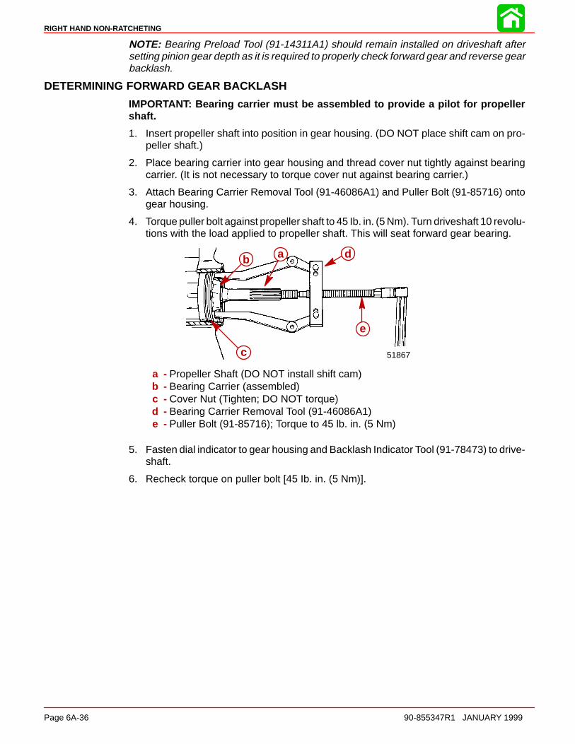
RIGHT HAND NON-RATCHETING
Page 6A-36 90-855347R1 JANUARY 1999
NOTE: Bearing Preload Tool (91-14311A1) should remain installed on driveshaft aftersetting pinion gear depth as it is required to properly check forward gear and reverse gearbacklash.
DETERMINING FORWARD GEAR BACKLASH
IMPORTANT: Bearing carrier must be assembled to provide a pilot for propellershaft.
1. Insert propeller shaft into position in gear housing. (DO NOT place shift cam on pro-peller shaft.)
2. Place bearing carrier into gear housing and thread cover nut tightly against bearingcarrier. (It is not necessary to torque cover nut against bearing carrier.)
3. Attach Bearing Carrier Removal Tool (91-46086A1) and Puller Bolt (91-85716) ontogear housing.
4. Torque puller bolt against propeller shaft to 45 Ib. in. (5 Nm). Turn driveshaft 10 revolu-tions with the load applied to propeller shaft. This will seat forward gear bearing.
51867
ab
c
d
e
a - Propeller Shaft (DO NOT install shift cam)b - Bearing Carrier (assembled)c - Cover Nut (Tighten; DO NOT torque)d - Bearing Carrier Removal Tool (91-46086A1)e - Puller Bolt (91-85716); Torque to 45 lb. in. (5 Nm)
5. Fasten dial indicator to gear housing and Backlash Indicator Tool (91-78473) to drive-shaft.
6. Recheck torque on puller bolt [45 Ib. in. (5 Nm)].

RIGHT HAND NON-RATCHETING
90-855347R1 JANUARY 1999 Page 6A-37
7. Position dial indicator pointer on line marked “1” on Backlash Indicator Tool, if gearratio is 1.87:1 (15 teeth on pinion gear), or on line marked “2” on Backlash IndicatorTool, if gear ratio is 2:1 (14 teeth on pinion gear) or on line marked “4” if gear ratio is2.3:1 (13 teeth on pinion gear).
51880
a
b
c
d
e
a - Thread Stud Adaptor (from 91-14311A1)b - Studc - Backlash Indicator Tool (91-78473)d - Dial Indicator Holder (91-89897)e - Dial Indicator (91-58222A1)
8. Lightly turn driveshaft back-and-forth (no movement should be noticed at propellershaft).
9. Dial indicator registers amount of backlash which must be 0.018 in. to 0.027 in. (0.46mm to 0.69 mm) for the 1.87:1 gear ratio, 0.015 in. to 0.022 in. (0.38 mm to 0.56 mm)for the 2:1 gear ratio and 0.018 in. to 0.023 in. (0.46 mm to 0.58 mm) for the 2.3:1 gearratio.
10. If backlash is LESS than the specified minimum, REMOVE shim(s) from in front of for-ward gear bearing race to obtain correct backlash. When reinstalling pinion nut, applyLoctite 271 on threads of nut.
11. If backlash is MORE than the specified MAXIMUM, add shim(s) in front of forwardgear bearing race to obtain correct backlash. When reinstalling pinion nut, apply Loc-tite 271 on threads of nut.
NOTE: By adding or subtracting 0.001 in. (0.025 mm) shim, the backlash will change ap-proximately 0.001 in. (0.025 mm ).
REVERSE GEAR
Determining Reverse Gear Backlash
Although reverse gear backlash is not adjustable, it may be checked as follows:
1. Propeller shaft and bearing carrier must be completely assembled and installed ingearcase.
2. Install shift shaft in gearcase.
3. Shift gearcase into reverse.
4. Slide 6 in. x 1.5 in. I.D. (152.5 mm x 38.0 mm) piece of PVC pipe over propeller shaftand position pipe against bearing carrier.

RIGHT HAND NON-RATCHETING
Page 6A-38 90-855347R1 JANUARY 1999
5. Secure pipe against carrier with propeller nut and tab washer.
51866
ab
c
a - Pipe [6 in. x 1.5 in. (152.5 mm x 38.0 mm)]b - Propeller Nutc - Tab Washer
6. Torque propeller nut to 45 lb. in. (5 Nm).
7. Gently rock driveshaft. Dial indicator should show backlash of 0.030 in.-0.050 in.(0.762 mm- 01.27 mm).
If backlash is not as indicated, gear case is not properly assembled or parts are excessive-ly worn and must be replaced before returning gear case to service.
Clutch Actuator RodREASSEMBLY
1. Place a small amount of Quicksilver 2-4-C w/Teflon Lubricant on actuator rod andinstall cam follower.
ab
a - Actuator Rodb - Cam Follower
Shift Shaft BushingREASSEMBLY
1. Position shift shaft bushing on a press with threaded side down.
2. Apply Loctite 271 to outside diameter of oil seal.
3. Press oil seal into shift shaft bushing with lip of seal up.
4. Wipe any excess Loctite from oil seal and bushing.
5. Place rubber washer against oil seal.
6. Install O-ring over threads and up against shoulder of bushing.
7. Lubricate O-ring and oil seal with Quicksilver 2-4-C w/Teflon Marine Lubricant.

RIGHT HAND NON-RATCHETING
90-855347R1 JANUARY 1999 Page 6A-39
Propeller ShaftREASSEMBLY/INSTALLATION
1. Insert clutch actuator rod assembly into end of propeller shaft. Align cross pin slot inactuator rod with cross pin slot in propeller shaft.
2. On PRODUCTION MODEL GEAR CASES, position sliding clutch onto propeller shaftwith GROOVED RINGS (ON SLIDING CLUTCH) TOWARD PROPELLER END OFPROPELLER SHAFT. Cross pin hole and detent holes (in sliding clutch) must line upwith cross pin slot and detent notches on propeller shaft.
51864
51864c
de
f
g h
a b
a - Cam Followerb - Propeller Shaftc - Sliding Clutchd - Grooved Ringse - Cross Pin Holef - Detent Hole (Behind Finger and Thumb)g - Detent Notch (One on Each Side)h - Cross Pin Slot
3. Insert cross pin thru sliding clutch, propeller shaft and actuator rod, forcing cross pintool out.
4. Apply a small amount of 2-4-C w/Teflon Marine Lubricant on detent pin. Position a det-ent pin in detent pin hole of sliding clutch with rounded end of pin toward propellershaft.
5186451864
bc
d
a
a - Cross Pinb - Detent Pinc - Cross Pind - Sliding Clutch
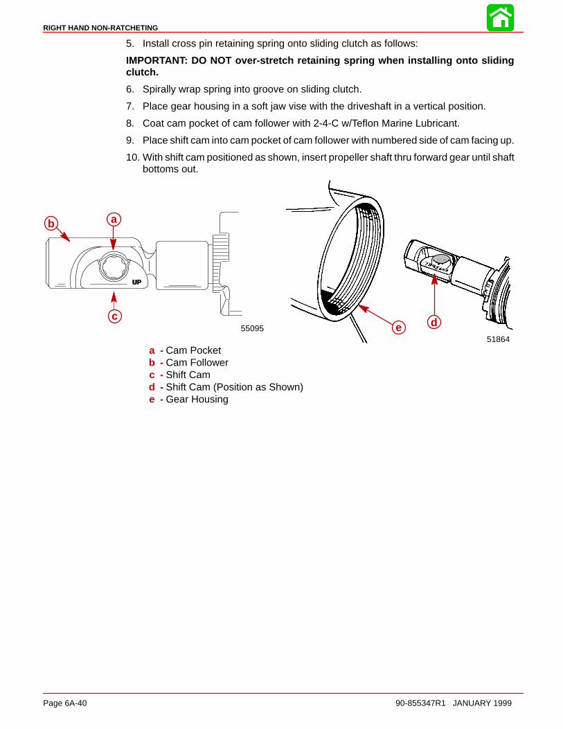
RIGHT HAND NON-RATCHETING
Page 6A-40 90-855347R1 JANUARY 1999
5. Install cross pin retaining spring onto sliding clutch as follows:
IMPORTANT: DO NOT over-stretch retaining spring when installing onto slidingclutch.
6. Spirally wrap spring into groove on sliding clutch.
7. Place gear housing in a soft jaw vise with the driveshaft in a vertical position.
8. Coat cam pocket of cam follower with 2-4-C w/Teflon Marine Lubricant.
9. Place shift cam into cam pocket of cam follower with numbered side of cam facing up.
10. With shift cam positioned as shown, insert propeller shaft thru forward gear until shaftbottoms out.
51864
de55095
ab
c
a - Cam Pocketb - Cam Followerc - Shift Camd - Shift Cam (Position as Shown)e - Gear Housing
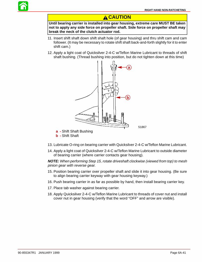
RIGHT HAND NON-RATCHETING
90-855347R1 JANUARY 1999 Page 6A-41
CAUTIONUntil bearing carrier is installed into gear housing, extreme care MUST BE takennot to apply any side force on propeller shaft. Side force on propeller shaft maybreak the neck of the clutch actuator rod.
11. Insert shift shaft down shift shaft hole (of gear housing) and thru shift cam and camfollower. (It may be necessary to rotate shift shaft back-and-forth slightly for it to entershift cam.)
12. Apply a light coat of Quicksilver 2-4-C w/Teflon Marine Lubricant to threads of shiftshaft bushing. (Thread bushing into position, but do not tighten down at this time)
51867
a
b
a - Shift Shaft Bushingb - Shift Shaft
13. Lubricate O-ring on bearing carrier with Quicksilver 2-4-C w/Teflon Marine Lubricant.
14. Apply a light coat of Quicksilver 2-4-C w/Teflon Marine Lubricant to outside diameterof bearing carrier (where carrier contacts gear housing).
NOTE: When performing Step 15, rotate driveshaft clockwise (viewed from top) to meshpinion gear with reverse gear.
15. Position bearing carrier over propeller shaft and slide it into gear housing. (Be sureto align bearing carrier keyway with gear housing keyway.)
16. Push bearing carrier in as far as possible by hand, then install bearing carrier key.
17. Place tab washer against bearing carrier.
18. Apply Quicksilver 2-4-C w/Teflon Marine Lubricant to threads of cover nut and installcover nut in gear housing (verify that the word “OFF” and arrow are visible).
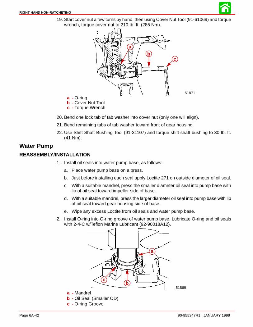
RIGHT HAND NON-RATCHETING
Page 6A-42 90-855347R1 JANUARY 1999
19. Start cover nut a few turns by hand, then using Cover Nut Tool (91-61069) and torquewrench, torque cover nut to 210 Ib. ft. (285 Nm).
51871
ab
c
a - O-ringb - Cover Nut Toolc - Torque Wrench
20. Bend one lock tab of tab washer into cover nut (only one will align).
21. Bend remaining tabs of tab washer toward front of gear housing.
22. Use Shift Shaft Bushing Tool (91-31107) and torque shift shaft bushing to 30 Ib. ft.(41 Nm).
Water PumpREASSEMBLY/INSTALLATION
1. Install oil seals into water pump base, as follows:
a. Place water pump base on a press.
b. Just before installing each seal apply Loctite 271 on outside diameter of oil seal.
c. With a suitable mandrel, press the smaller diameter oil seal into pump base withlip of oil seal toward impeller side of base.
d. With a suitable mandrel, press the larger diameter oil seal into pump base with lipof oil seal toward gear housing side of base.
e. Wipe any excess Loctite from oil seals and water pump base.
2. Install O-ring into O-ring groove of water pump base. Lubricate O-ring and oil sealswith 2-4-C w/Teflon Marine Lubricant (92-90018A12).
51869
a
bc
a - Mandrelb - Oil Seal (Smaller OD)c - O-ring Groove

RIGHT HAND NON-RATCHETING
90-855347R1 JANUARY 1999 Page 6A-43
3. Install divider block if removed. Use RTV Sealer to seal seams between divider blockand gear housing.
4. Install a new water pump base gasket and install water pump base.
51866
51870
b c
d
a
a - Divider Blockb - Water Pump Basec - Gasketd - Hole (MUST be positioned as shown)
5. Install the following in order: Pump base to face plate gasket, face plate gasket andface plate to pump cover gasket. Gaskets and face plate are indexed by dowel pinlocation and must be installed correctly.
51868
a
b
c
a - Gasket (Water Pump Base to Face Plate)b - Face Platec - Gasket (Face Plate to Water Pump Cover)
6. Place impeller drive key on flat of driveshaft. Hold key on driveshaft with a smallamount of Quicksilver 2-4-C w/Teflon Marine Lubricant.
IMPORTANT: When completing gear housing repair, that requires removal of waterpump impeller, it is recommended that the impeller be replaced. If it is necessary,however, to reuse the impeller, DO NOT install in reverse to original rotation, or pre-mature impeller failure will occur. Original rotation is clockwise.
CAUTIONA visual inspection of impeller drive key MUST BE made to determine that drivekey is on flat of driveshaft after impeller is installed. If key has moved off flat ofdriveshaft, repeat Steps 7 and 8.
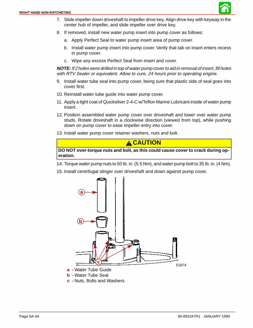
RIGHT HAND NON-RATCHETING
Page 6A-44 90-855347R1 JANUARY 1999
7. Slide impeller down driveshaft to impeller drive key. Align drive key with keyway in thecenter hub of impeller, and slide impeller over drive key.
8. If removed, install new water pump insert into pump cover as follows:
a. Apply Perfect Seal to water pump insert area of pump cover.
b. Install water pump insert into pump cover. Verify that tab on insert enters recessin pump cover.
c. Wipe any excess Perfect Seal from insert and cover.
NOTE: If 2 holes were drilled in top of water pump cover to aid in removal of insert, fill holeswith RTV Sealer or equivalent. Allow to cure, 24 hours prior to operating engine.
9. Install water tube seal into pump cover, being sure that plastic side of seal goes intocover first.
10. Reinstall water tube guide into water pump cover.
11. Apply a light coat of Quicksilver 2-4-C w/Teflon Marine Lubricant inside of water pumpinsert.
12. Position assembled water pump cover over driveshaft and lower over water pumpstuds. Rotate driveshaft in a clockwise direction (viewed from top), while pushingdown on pump cover to ease impeller entry into cover.
13. Install water pump cover retainer washers, nuts and bolt.
CAUTIONDO NOT over-torque nuts and bolt, as this could cause cover to crack during op-eration.
14. Torque water pump nuts to 50 Ib. in. (5.5 Nm), and water pump bolt to 35 Ib. in. (4 Nm).
15. Install centrifugal slinger over driveshaft and down against pump cover.
51874
a
b
c
a - Water Tube Guideb - Water Tube Sealc - Nuts, Bolts and Washers

RIGHT HAND NON-RATCHETING
90-855347R1 JANUARY 1999 Page 6A-45
Gear Lubricant Filling Instructions1. Remove any gasket material from “Fill” and “Vent” screws and gear housing.
2. Install new gaskets on Fill and Vent screws.
IMPORTANT: Never apply lubricant to gear housing without first removing Ventscrew, or gear housing cannot be filled because of trapped air. Fill gear housingONLY when housing is in a vertical position.
3. Slowly fill housing thru Fill hole with Quicksilver Super Duty Lower Unit Lubricant untillubricant flows out of “Vent” hole and no air bubbles are visible.
4. Install Vent screw into Vent hole.
IMPORTANT: DO NOT lose more than one fluid ounce (30cc) of gear lubricant whilereinstalling Fill screw.
5. Remove grease tube (or hose) from Fill hole and quickly install Fill screw into Fill hole.
Installing Gear Housing to Driveshaft Housing
WARNINGDisconnect high tension leads from spark plugs and remove spark plugs fromengine before installing gear housing onto driveshaft housing.
1. Tilt engine to full up position and engage the tilt lock lever.
2. Apply a light coat of Quicksilver 2-4-C w/Teflon Marine Lubricant onto driveshaftsplines.
CAUTIONDO NOT allow lubricant on top of driveshaft. Excess lubricant, that is trapped inclearance space, will not allow driveshaft to fully engage with crankshaft. Subse-quently, tightening the gear housing nuts (while excess lubricant is on top of dri-veshaft) will load the driveshaft/crankshaft and damage either or both the power-head and gear housing. Top of driveshaft is to be wiped free of lubricant.
3. Apply a light coat of Quicksilver 2-4-C w/Teflon Marine Lubricant onto shift shaftsplines. (DO NOT allow lubricant on top of shift shaft.)
4. Apply a thin bead of G.E. Silicone Sealer (92-91600-1) against the top of divider block.
5. Insert trim tab bolt into hole in rear of gear housing to driveshaft housing machinedsurface.
6. Shift gear housing into forward gear and place guide block anchor pin into forwardgear position.
51900a
a - Guide Block Anchor Pin
7. Position gear housing so that the driveshaft is protruding into driveshaft housing.
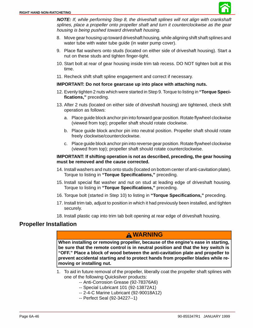
RIGHT HAND NON-RATCHETING
Page 6A-46 90-855347R1 JANUARY 1999
NOTE: If, while performing Step 8, the driveshaft splines will not align with crankshaftsplines, place a propeller onto propeller shaft and turn it counterclockwise as the gearhousing is being pushed toward driveshaft housing.
8. Move gear housing up toward driveshaft housing, while aligning shift shaft splines andwater tube with water tube guide (in water pump cover).
9. Place flat washers onto studs (located on either side of driveshaft housing). Start anut on these studs and tighten finger-tight.
10. Start bolt at rear of gear housing inside trim tab recess. DO NOT tighten bolt at thistime.
11. Recheck shift shaft spline engagement and correct if necessary.
IMPORTANT: Do not force gearcase up into place with attaching nuts.
12. Evenly tighten 2 nuts which were started in Step 9. Torque to listing in “Torque Speci-fications,” preceding.
13. After 2 nuts (located on either side of driveshaft housing) are tightened, check shiftoperation as follows:
a. Place guide block anchor pin into forward gear position. Rotate flywheel clockwise(viewed from top); propeller shaft should rotate clockwise.
b. Place guide block anchor pin into neutral position. Propeller shaft should rotatefreely clockwise/counterclockwise.
c. Place guide block anchor pin into reverse gear position. Rotate flywheel clockwise(viewed from top); propeller shaft should rotate counterclockwise.
IMPORTANT: lf shifting operation is not as described, preceding, the gear housingmust be removed and the cause corrected.
14. Install washers and nuts onto studs (located on bottom center of anti-cavitation plate).Torque to listing in “Torque Specifications,” preceding.
15. Install special flat washer and nut on stud at leading edge of driveshaft housing.Torque to listing in “Torque Specifications,” preceding.
16. Torque bolt (started in Step 10) to listing in “Torque Specifications,” preceding.
17. Install trim tab, adjust to position in which it had previously been installed, and tightensecurely.
18. Install plastic cap into trim tab bolt opening at rear edge of driveshaft housing.
Propeller Installation
WARNINGWhen installing or removing propeller, because of the engine’s ease in starting,be sure that the remote control is in neutral position and that the key switch is“OFF.” Place a block of wood between the anti-cavitation plate and propeller toprevent accidental starting and to protect hands from propeller blades while re-moving or installing nut.
1. To aid in future removal of the propeller, liberally coat the propeller shaft splines withone of the following Quicksilver products:
-- Anti-Corrosion Grease (92-78376A6)-- Special Lubricant 101 (92-13872A1)-- 2-4-C Marine Lubricant (92-90018A12)-- Perfect Seal (92-34227--1)
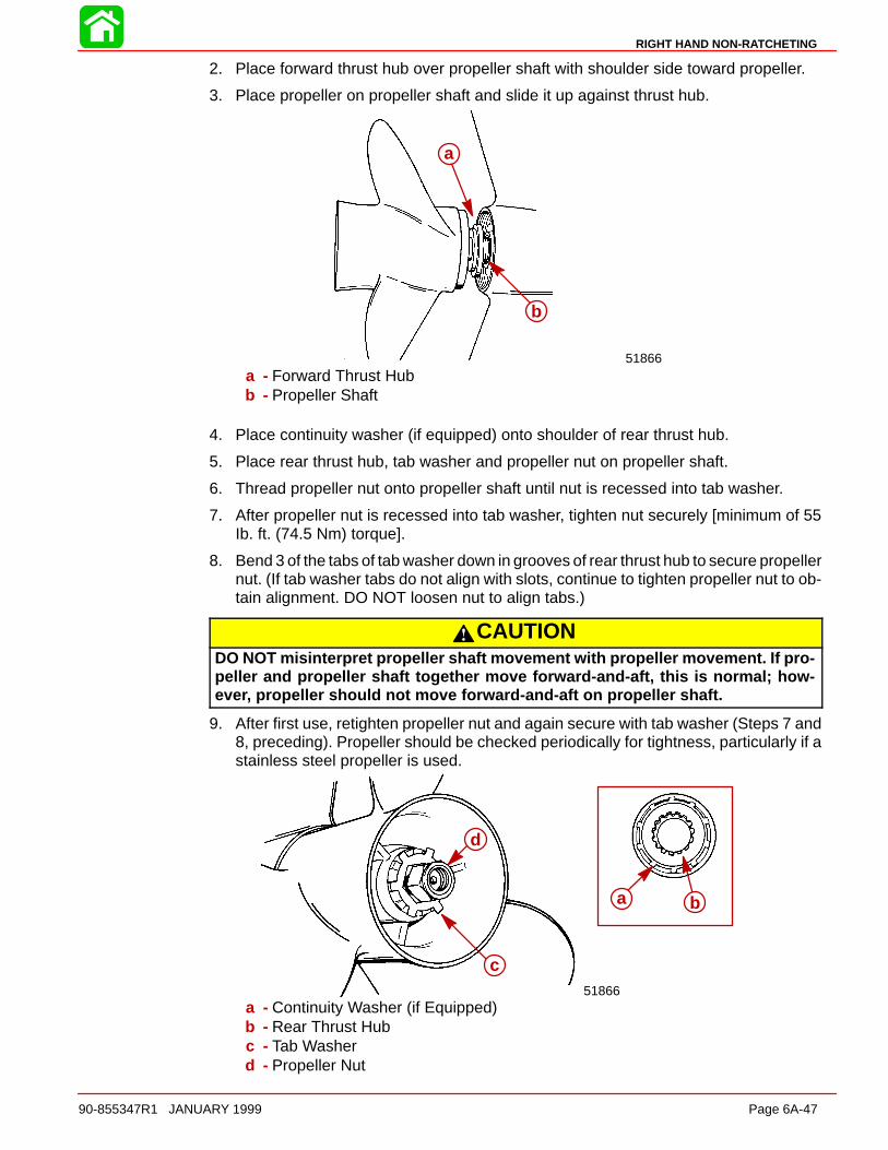
RIGHT HAND NON-RATCHETING
90-855347R1 JANUARY 1999 Page 6A-47
2. Place forward thrust hub over propeller shaft with shoulder side toward propeller.
3. Place propeller on propeller shaft and slide it up against thrust hub.
51866
a
b
a - Forward Thrust Hubb - Propeller Shaft
4. Place continuity washer (if equipped) onto shoulder of rear thrust hub.
5. Place rear thrust hub, tab washer and propeller nut on propeller shaft.
6. Thread propeller nut onto propeller shaft until nut is recessed into tab washer.
7. After propeller nut is recessed into tab washer, tighten nut securely [minimum of 55Ib. ft. (74.5 Nm) torque].
8. Bend 3 of the tabs of tab washer down in grooves of rear thrust hub to secure propellernut. (If tab washer tabs do not align with slots, continue to tighten propeller nut to ob-tain alignment. DO NOT loosen nut to align tabs.)
CAUTIONDO NOT misinterpret propeller shaft movement with propeller movement. If pro-peller and propeller shaft together move forward-and-aft, this is normal; how-ever, propeller should not move forward-and-aft on propeller shaft.
9. After first use, retighten propeller nut and again secure with tab washer (Steps 7 and8, preceding). Propeller should be checked periodically for tightness, particularly if astainless steel propeller is used.
51866
a b
c
d
a - Continuity Washer (if Equipped)b - Rear Thrust Hubc - Tab Washerd - Propeller Nut
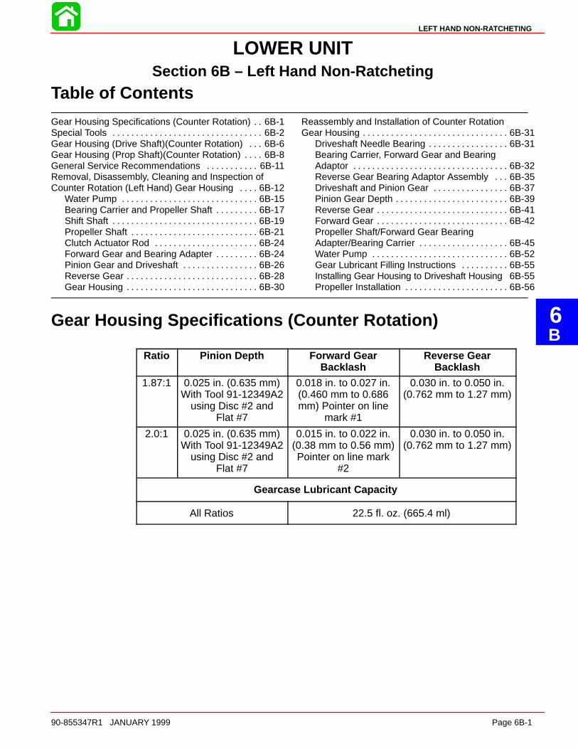
6B
LEFT HAND NON-RATCHETING
90-855347R1 JANUARY 1999 Page 6B-1
LOWER UNITSection 6B – Left Hand Non-Ratcheting
Table of Contents
Gear Housing Specifications (Counter Rotation) 6B-1. . Special Tools 6B-2. . . . . . . . . . . . . . . . . . . . . . . . . . . . . . . . Gear Housing (Drive Shaft)(Counter Rotation) 6B-6. . . Gear Housing (Prop Shaft)(Counter Rotation) 6B-8. . . . General Service Recommendations 6B-11. . . . . . . . . . . Removal, Disassembly, Cleaning and Inspection ofCounter Rotation (Left Hand) Gear Housing 6B-12. . . .
Water Pump 6B-15. . . . . . . . . . . . . . . . . . . . . . . . . . . . . Bearing Carrier and Propeller Shaft 6B-17. . . . . . . . . Shift Shaft 6B-19. . . . . . . . . . . . . . . . . . . . . . . . . . . . . . . Propeller Shaft 6B-21. . . . . . . . . . . . . . . . . . . . . . . . . . . Clutch Actuator Rod 6B-24. . . . . . . . . . . . . . . . . . . . . . Forward Gear and Bearing Adapter 6B-24. . . . . . . . . Pinion Gear and Driveshaft 6B-26. . . . . . . . . . . . . . . . Reverse Gear 6B-28. . . . . . . . . . . . . . . . . . . . . . . . . . . . Gear Housing 6B-30. . . . . . . . . . . . . . . . . . . . . . . . . . . .
Reassembly and Installation of Counter RotationGear Housing 6B-31. . . . . . . . . . . . . . . . . . . . . . . . . . . . . . .
Driveshaft Needle Bearing 6B-31. . . . . . . . . . . . . . . . . Bearing Carrier, Forward Gear and BearingAdaptor 6B-32. . . . . . . . . . . . . . . . . . . . . . . . . . . . . . . . . Reverse Gear Bearing Adaptor Assembly 6B-35. . . Driveshaft and Pinion Gear 6B-37. . . . . . . . . . . . . . . . Pinion Gear Depth 6B-39. . . . . . . . . . . . . . . . . . . . . . . . Reverse Gear 6B-41. . . . . . . . . . . . . . . . . . . . . . . . . . . . Forward Gear 6B-42. . . . . . . . . . . . . . . . . . . . . . . . . . . . Propeller Shaft/Forward Gear BearingAdapter/Bearing Carrier 6B-45. . . . . . . . . . . . . . . . . . . Water Pump 6B-52. . . . . . . . . . . . . . . . . . . . . . . . . . . . . Gear Lubricant Filling Instructions 6B-55. . . . . . . . . . Installing Gear Housing to Driveshaft Housing 6B-55Propeller Installation 6B-56. . . . . . . . . . . . . . . . . . . . . .
Gear Housing Specifications (Counter Rotation)
Ratio Pinion Depth Forward GearBacklash
Reverse GearBacklash
1.87:1 0.025 in. (0.635 mm)With Tool 91-12349A2
using Disc #2 andFlat #7
0.018 in. to 0.027 in.(0.460 mm to 0.686mm) Pointer on line
mark #1
0.030 in. to 0.050 in.(0.762 mm to 1.27 mm)
2.0:1 0.025 in. (0.635 mm)With Tool 91-12349A2
using Disc #2 andFlat #7
0.015 in. to 0.022 in.(0.38 mm to 0.56 mm)Pointer on line mark
#2
0.030 in. to 0.050 in.(0.762 mm to 1.27 mm)
Gearcase Lubricant Capacity
All Ratios 22.5 fl. oz. (665.4 ml)

LEFT HAND NON-RATCHETING
Page 6B-2 90-855347R1 JANUARY 1999
Special Tools
1. Shift Shaft Bushing Tool 91-31107T
2. Gear Housing Cover Nut Tool 91-61069
3. Bearing Carrier Removal Tool 91-46086A1 and Puller Bolt 91-85716
4. Slide Hammer Puller 91-34569A1
5. Bearing Removal and Installation Kit 91-31229A5. This kit contains the followingtools: Pilot 91-36571; Puller Rod 91-31229; Nut 11-24156; Puller Plate 91-29310;Mandrel 91-38628; and Driver Rod 91-37323.
6. Pilot 91-36571
7. Puller Rod 91-31229 and Nut 91-24156

LEFT HAND NON-RATCHETING
90-855347R1 JANUARY 1999 Page 6B-3
8. Puller Plate 91-29310
9. Mandrel 91-38628
10. Driver Rod 91-37323
11. Universal Puller Plate 91-37241
12. Driveshaft Holding Tool 91-34377A1 or91-90094
13. Oil Seal Driver 91-31108
14. Forward Gear Bearing Tool 91-86943
15. Pinion Locating Gear Tool 91-12349A2 or 91-74776
16. Backlash Indicator Rod 91-78473
17. Dial Indicator 91-58222A1
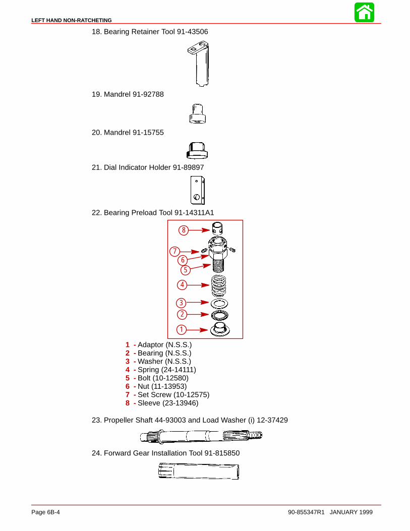
LEFT HAND NON-RATCHETING
Page 6B-4 90-855347R1 JANUARY 1999
18. Bearing Retainer Tool 91-43506
19. Mandrel 91-92788
20. Mandrel 91-15755
21. Dial Indicator Holder 91-89897
22. Bearing Preload Tool 91-14311A1
1
2
3
4
56
7
8
1 - Adaptor (N.S.S.)2 - Bearing (N.S.S.)3 - Washer (N.S.S.)4 - Spring (24-14111)5 - Bolt (10-12580)6 - Nut (11-13953)7 - Set Screw (10-12575)8 - Sleeve (23-13946)
23. Propeller Shaft 44-93003 and Load Washer (i) 12-37429
24. Forward Gear Installation Tool 91-815850
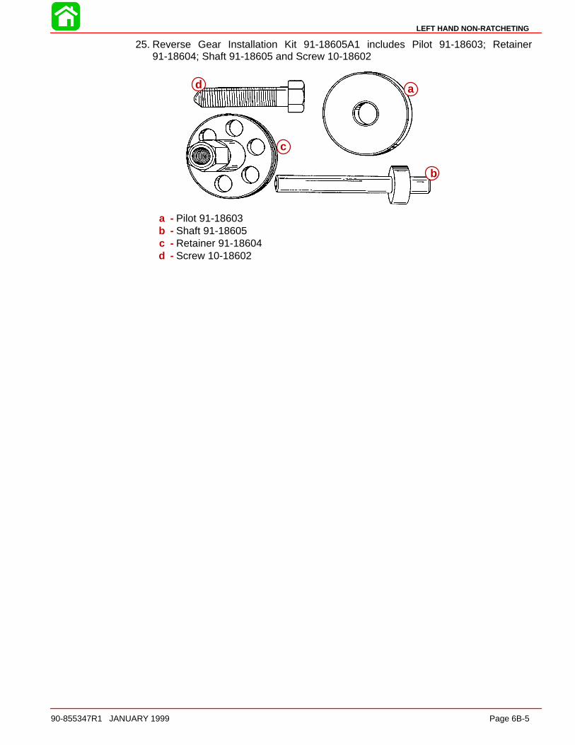
LEFT HAND NON-RATCHETING
90-855347R1 JANUARY 1999 Page 6B-5
25. Reverse Gear Installation Kit 91-18605A1 includes Pilot 91-18603; Retainer91-18604; Shaft 91-18605 and Screw 10-18602
a
b
c
d
a - Pilot 91-18603b - Shaft 91-18605c - Retainer 91-18604d - Screw 10-18602

LEFT HAND NON-RATCHETING
Page 6B-6 90-855347R1 JANUARY 1999
Gear Housing (Drive Shaft)(Counter Rotation)
23
95
95
7
95
95
95
98
33
795
95
7
95
19
95
109
95
Soap (Purchase Locally)23
4.75 IN./120.65 MMTORPEDO DIA.
7 Loctite 271 (92-809820)
Perfect Seal (92-34227-1)19
Loctite 680 (92-809833)33
95 2-4-C With Teflon (92-825407A12)
109 GM Silicone Sealer (92-91600-1)
1
2
3
4
5
6
7
8
9
10
10
11
12
131415
16
17
1819
20
21
2223
242526
27
28
29
30
31
32
3334
35
36
37
38
39
40
41
4243
444546
47
48
49
50
7
19

LEFT HAND NON-RATCHETING
90-855347R1 JANUARY 1999 Page 6B-7
Gear Housing (Drive Shaft)(Counter Rotation)
REF. TORQUEREF.NO. QTY. DESCRIPTION lb-in lb-ft Nm.
1 1 GEAR HOUSING (BLACK)(BASIC)2 1 CONNECTOR ASSEMBLY3 2 DOWEL PIN4 1 STUD (3-11/16 IN.)5 2 STUD (2-1/16 IN.)6 1 STUD (3-3/8 IN.)7 2 STUD (3-1/8 IN.)8 1 FILLER BLOCK9 1 ROLLER BEARING10 2 ANODE11 1 SCREW12 1 NUT 60 7
131 PINION GEAR (1.87:1 - 15 TEETH)(150)(Part of 43-828701A1)
13 1 PINION GEAR (2:1 - 14 TEETH)-(135)(Also part of 43-828703A1)14 1 WASHER15 1 NUT 75 10116 AR SHIM SET17 1 SCREW–drain (MAGNETIC) 60 718 1 SCREW–grease filler 60 719 2 WASHER20 1 STA-STRAP21 1 SHIFT SHAFT22 1 O-RING23 1 BUSHING ASSEMBLY 50 5.524 1 OIL SEAL25 1 WASHER–rubber26 1 DRIVE SHAFT27 1 ROLLER BEARING28 1 CUP29 1 RETAINER 100 11.530 1 WATER PUMP BASE31 1 RETAINER32 1 GASKET33 1 O-RING34 1 OIL SEAL35 1 OIL SEAL36 1 GASKET–lower37 1 GASKET–upper38 1 FACE PLATE39 1 WATER PUMP BODY ASSEMBLY40 1 INSERT41 1 SEAL–rubber42 1 lMPELLER43 1 KEY44 1 SCREW (#14-8 x 2-1/4 IN.) 35 445 2 WASHER46 2 NUT 50 5.547 1 WASHER48 1 NUT 50 5.549 1 SLEEVE50 1 DECAL-Counter Rotation

LEFT HAND NON-RATCHETING
Page 6B-8 90-855347R1 JANUARY 1999
Gear Housing (Prop Shaft)(Counter Rotation)
1
68
69
70
71
7273
7475
76
77
787980
81
82
83
84
85
86
8788
7473
72
95
87
87
95
8787
87
87
94
95
877
95
95
95
87
87
4.75 IN./120.65 MMTORPEDO DIA.
7 Loctite 271 (92-809820) 94 Anti-Corrosion Grease (92-78376A6)
95 2-4-C With Teflon (92-825407A12)87 Quicksilver Gear Lubricant (92-19007A24)
51
52
53
54
5556
57
58
59
60
6162
6364
6566
67

LEFT HAND NON-RATCHETING
90-855347R1 JANUARY 1999 Page 6B-9
Gear Housing (Prop Shaft)(Counter Rotation)
REF. TORQUEREF.NO. QTY. DESCRIPTION lb-in lb-ft Nm.
1 1 GEAR HOUSING (BLACK)(BASIC)51 1 CAM FOLLOWER52 1 SHIFT CAM53 1 ROD54 AR SHIM SET55 1 BEARING ADAPTOR ASSEMBLY56 1 ROLLER BEARING
57 1 THRUST WASHER58 1 THRUST BEARING
591 REVERSE GEAR (1.87:1 – 15/28)(150)
591 REVERSE GEAR (2:1 – 14/28)-(135)
60 1 ROLLER BEARING61 1 SPRING62 1 SLIDING CLUTCH
63 1 CROSS PIN64 1 DETENT PIN65 1 PROPELLER SHAFT
661 FORWARD GEAR (1.87:1 – 15/28)(150)
661 FORWARD GEAR (2:1 – 14/28)-(135)
AR SPACER SHIM .206 IN.AR SPACER SHIM .208 IN.
AR SPACER SHIM .210 IN.AR SPACER SHIM .212 IN.AR SPACER SHIM .214 IN.AR SPACER SHIM .216 IN.
67 AR SPACER SHIM .218 IN.AR SPACER SHIM .220 IN.AR SPACER SHIM .222 IN.
AR SPACER SHIM .224 IN.AR SPACER SHIM .226 IN.AR SPACER SHIM .228 IN.AR SPACER SHIM .230 IN.

LEFT HAND NON-RATCHETING
Page 6B-10 90-855347R1 JANUARY 1999
Gear Housing (Prop Shaft)(Counter Rotation)
1
68
69
70
71
7273
7475
76
77
7879
80
81
82
83
84
85
86
87
88
7473
72
95
87
87
95
8787
87
87
94
95
877
95
95
95
87
87
4.75 IN./120.65 MMTORPEDO DIA.
7 Loctite 271 (92-809820)
87 Quicksilver Gear Lubricant (92-19007A24)
94 Anti-Corrosion Grease (92-78376A6)
95 2-4-C With Teflon (92-825407A12)
51
52
53
54
5556
57
58
59
60
6162
6364
6566
67
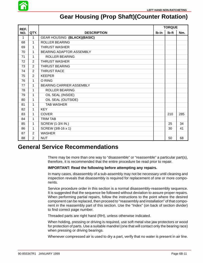
LEFT HAND NON-RATCHETING
90-855347R1 JANUARY 1999 Page 6B-11
Gear Housing (Prop Shaft)(Counter Rotation)
REF. TORQUEREF.NO. QTY. DESCRIPTION lb-in lb-ft Nm.
1 1 GEAR HOUSING (BLACK)(BASIC)68 1 ROLLER BEARING69 1 THRUST WASHER70 1 BEARING ADAPTOR ASSEMBLY71 1 ROLLER BEARING72 2 THRUST WASHER73 2 THRUST BEARING
74 2 THRUST RACE75 2 KEEPER76 1 O RING77 1 BEARING CARRIER ASSEMBLY78 1 ROLLER BEARING79 1 OIL SEAL (INSIDE)80 1 OIL SEAL (OUTSIDE)
81 1 TAB WASHER82 1 KEY83 1 COVER 210 28584 1 TRIM TAB85 1 SCREW (1-3/4 IN.) 25 3486 1 SCREW (3/8-16 x 1) 30 4187 2 WASHER
88 2 NUT 50 68
General Service Recommendations
There may be more than one way to “disassemble” or “reassemble” a particular part(s),therefore, it is recommended that the entire procedure be read prior to repair.
IMPORTANT: Read the following before attempting any repairs.
In many cases, disassembly of a sub-assembly may not be necessary until cleaning andinspection reveals that disassembly is required for replacement of one or more compo-nents.
Service procedure order in this section is a normal disassembly-reassembly sequence.It is suggested that the sequence be followed without deviation to assure proper repairs.When performing partial repairs, follow the instructions to the point where the desiredcomponent can be replaced, then proceed to “reassembly and installation” of that compo-nent in the reassembly part of this section. Use the “Index” (on back of section divider)to find correct page number.
Threaded parts are right hand (RH), unless otherwise indicated.
When holding, pressing or driving is required, use soft metal vise jaw protectors or woodfor protection of parts. Use a suitable mandrel (one that will contact only the bearing race)when pressing or driving bearings.
Whenever compressed air is used to dry a part, verify that no water is present in air line.

LEFT HAND NON-RATCHETING
Page 6B-12 90-855347R1 JANUARY 1999
BEARINGS
Upon disassembly of gear housing, all bearings must be cleaned and inspected. Cleanbearings with solvent and dry with compressed air. Air should be directed at the bearingso that it passes thru the bearing. DO NOT spin bearing with compressed air, as this maycause bearing to score from lack of lubrication. After cleaning, lubricate bearings withQuicksilver Gear Lubricant. DO NOT lubricate tapered bearing cups until after inspection.
Inspect all bearings for roughness, catches and bearing race side wear. Work inner bear-ing race in-and-out, while holding outer race, to check for side wear. When inspecting ta-pered bearings, determine condition of rollers and inner bearing race by inspecting bear-ing cup for pitting, scoring, grooves, uneven wear, imbedded particles and/ordiscoloration from over-heating. Always replace tapered bearing and race as a set.
Roller bearing condition is determined by inspecting the bearing surface of the shaft thatthe roller bearing supports. Check shaft surface for pitting, scoring, grooving, imbeddedparticles, uneven wear and/or discoloration from overheating. The shaft and bearing mustbe replaced, if the conditions described are found.
SHIMS
Keep a record of all shim amounts and location during disassembly to aid in reassembly.Be sure to follow shimming instructions during reassembly, as gears must be installed tocorrect depth and have the correct amount of backlash to avoid noisy operation and pre-mature gear failure.
SEALS
As a normal procedure, all O-rings and oil seals SHOULD BE REPLACED without regardto appearance. To prevent leakage around oil seals, apply Loctite 271 to outer diameterof all metal case oil seals. When using Loctite on seals or threads, surfaces must be cleanand dry. To ease installation, apply 2-4-C w/Teflon Marine Lubricant on all O-rings. To pre-vent wear, apply 2-4-C w/Teflon Marine Lubricant on l.D. of oil seals. To prevent corrosiondamage after reassembly, apply Quicksilver 2-4-C w/Teflon to external surfaces of bear-ing carrier and cover nut threads prior to installation.
Removal, Disassembly, Cleaning and Inspection of CounterRotation (Left Hand) Gear Housing
REMOVAL
WARNINGDisconnect high tension leads from spark plugs and remove spark plugs fromengine before removing gear housing from driveshaft housing.
1. Disconnect high tension leads from spark plugs and remove spark plugs from engine.
CAUTIONGear housing MUST BE in NEUTRAL position and shift shaft MUST BE removedfrom gear housing BEFORE propeller shaft can be removed from gear housing.
2. Shift engine into NEUTRAL position.
3. Tilt engine to full up position and engage tilt lock lever.
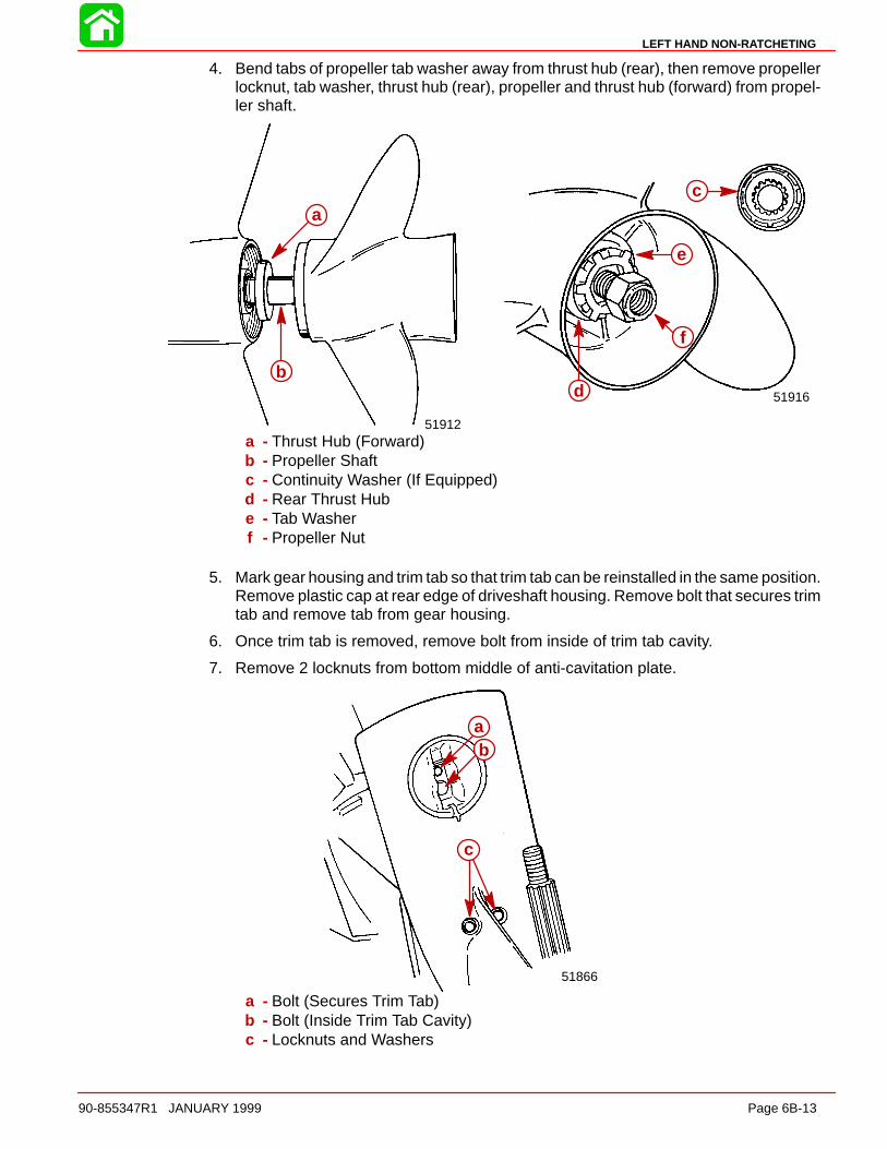
LEFT HAND NON-RATCHETING
90-855347R1 JANUARY 1999 Page 6B-13
4. Bend tabs of propeller tab washer away from thrust hub (rear), then remove propellerlocknut, tab washer, thrust hub (rear), propeller and thrust hub (forward) from propel-ler shaft.
51916
51912
a
b
c
d
e
f
a - Thrust Hub (Forward)b - Propeller Shaftc - Continuity Washer (If Equipped)d - Rear Thrust Hube - Tab Washerf - Propeller Nut
5. Mark gear housing and trim tab so that trim tab can be reinstalled in the same position.Remove plastic cap at rear edge of driveshaft housing. Remove bolt that secures trimtab and remove tab from gear housing.
6. Once trim tab is removed, remove bolt from inside of trim tab cavity.
7. Remove 2 locknuts from bottom middle of anti-cavitation plate.
51866
ab
c
a - Bolt (Secures Trim Tab)b - Bolt (Inside Trim Tab Cavity)c - Locknuts and Washers

LEFT HAND NON-RATCHETING
Page 6B-14 90-855347R1 JANUARY 1999
8. Remove locknut from the front gear housing mounting stud.
9. Loosen the side mounting locknuts. (DO NOT attempt to remove one nut before oppo-site side is loosened sufficiently, or driveshaft housing could be damaged.)
51873
ab
a - Front Mounting Locknutb - Side Mounting Locknut (One Each Side)
10. Pull gear housing away from driveshaft housing as far as the loosened nuts (in Step9) will allow, then remove loosened nuts. (DO NOT allow gear housing to fall, as it nowis free.)
11. Pull gear housing from driveshaft housing.
DRAINING AND INSPECTING GEAR HOUSING LUBRICANT
1. Place gear housing in a suitable holding fixture or vise with the driveshaft in a verticalposition, as shown.
NOTE: Drain and Fill screws may be located on the starboard side of gearcase on latermodels.
2. Position a clean drain pan under gear housing and remove “Fill” and “Vent” screwsfrom gear housing.
3. Inspect gear lubricant for metal particles. Presence of a small amount of fine metalparticles (resembling powder) indicates normal wear. Presence of larger particles (ora large quantity of fine particles) indicates need for gear housing disassembly, andcomponent inspection.
4. Note the color of gear lubricant. White or cream color indicates presence of water inlubricant. Check drain pan for water separation from lubricant. Presence of water ingear lubricant indicates the need for disassembly, and inspection of oil seals, seal sur-faces, O-rings and gear housing components.
IMPORTANT: Gear lubricant drained from a recently run gear case will be a lightchocolate brown in color due to agitation/aeration. Oil which is stabilized will bea clear yellow brown in color.
51871a
b
a - Fill Screwb - Vent Screw

LEFT HAND NON-RATCHETING
90-855347R1 JANUARY 1999 Page 6B-15
Water PumpCLEANING AND INSPECTION
1. Clean all water pump parts with solvent and dry with compressed air.
2. Inspect water pump cover and base for cracks and distortion (from overheating).
3. Inspect face plate and water pump insert for grooves and/or rough surfaces.
IMPORTANT: When completing gear housing repairs, that require removal of waterpump impeller, it is recommended that the impeller be replaced. If it is necessary,however, to re-use impeller, DO NOT install in reverse to original rotation, or prema-ture impeller failure will occur.
4. Inspect impeller side seal surfaces and ends of impeller blades for cracks, tears andwear. Replace impeller if any of these conditions are found.
5. Inspect impeller bonding to impeller hub.
6. Inspect impeller for glazed or melted appearance (caused by operation without suffi-cient water supply). Replace impeller if any of these conditions exist.
IMPORTANT: It is recommended that all seals and gaskets be replaced (as a normalrepair procedure) to assure effective repair.
REMOVAL AND DISASSEMBLY
1. Slide rubber centrifugal slinger up and off driveshaft.
2. Remove water tube guide and seal from water pump cover. (Retain guide for reas-sembly and discard seal.)
3. Remove (and retain) 3 nuts, one bolt and all washers which secure water pump coverto gear housing.
4. Using 2 pry bars, lift water pump cover up and off driveshaft.
51874
51874
a
b
c
a - Water Tube Guideb - Water Tube Sealc - Nuts, Bolt and Washers to be Removed
5. Inspect water pump cover and insert, as outlined in “Cleaning and Inspection,” pre-vious.
6. If inspection of water pump insert determines that replacement is required, follow Step“a” or “b” (immediately following) to remove insert from water pump cover.
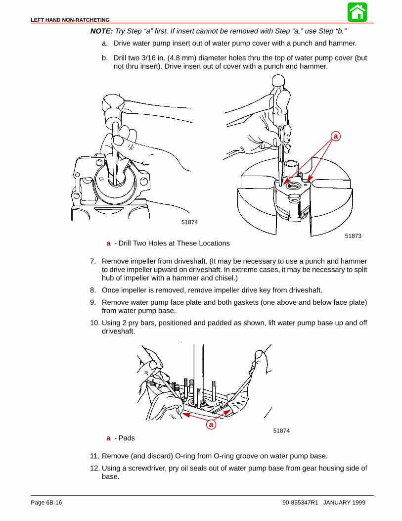
LEFT HAND NON-RATCHETING
Page 6B-16 90-855347R1 JANUARY 1999
NOTE: Try Step “a” first. If insert cannot be removed with Step “a,” use Step “b.”
a. Drive water pump insert out of water pump cover with a punch and hammer.
b. Drill two 3/16 in. (4.8 mm) diameter holes thru the top of water pump cover (butnot thru insert). Drive insert out of cover with a punch and hammer.
51873
51874
a
a - Drill Two Holes at These Locations
7. Remove impeller from driveshaft. (It may be necessary to use a punch and hammerto drive impeller upward on driveshaft. In extreme cases, it may be necessary to splithub of impeller with a hammer and chisel.)
8. Once impeller is removed, remove impeller drive key from driveshaft.
9. Remove water pump face plate and both gaskets (one above and below face plate)from water pump base.
10. Using 2 pry bars, positioned and padded as shown, lift water pump base up and offdriveshaft.
51874a
a - Pads
11. Remove (and discard) O-ring from O-ring groove on water pump base.
12. Using a screwdriver, pry oil seals out of water pump base from gear housing side ofbase.
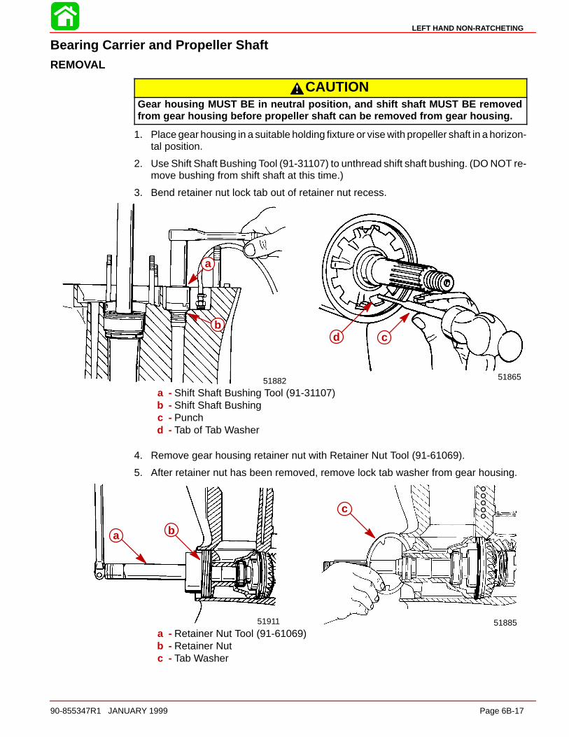
LEFT HAND NON-RATCHETING
90-855347R1 JANUARY 1999 Page 6B-17
Bearing Carrier and Propeller ShaftREMOVAL
CAUTIONGear housing MUST BE in neutral position, and shift shaft MUST BE removedfrom gear housing before propeller shaft can be removed from gear housing.
1. Place gear housing in a suitable holding fixture or vise with propeller shaft in a horizon-tal position.
2. Use Shift Shaft Bushing Tool (91-31107) to unthread shift shaft bushing. (DO NOT re-move bushing from shift shaft at this time.)
3. Bend retainer nut lock tab out of retainer nut recess.
51865
cd
51882
a
b
a - Shift Shaft Bushing Tool (91-31107)b - Shift Shaft Bushingc - Punchd - Tab of Tab Washer
4. Remove gear housing retainer nut with Retainer Nut Tool (91-61069).
5. After retainer nut has been removed, remove lock tab washer from gear housing.
5188551911
c
a b
a - Retainer Nut Tool (91-61069)b - Retainer Nutc - Tab Washer

LEFT HAND NON-RATCHETING
Page 6B-18 90-855347R1 JANUARY 1999
CAUTIONOnce bearing carrier is removed from gear housing, extreme care MUST BE takennot to apply any side force on propeller shaft. Side force on propeller shaft maybreak the neck of the clutch actuator rod.
6. Use long Puller Jaws (91-46086A1) and Puller Bolt (91-85716) to remove bearing car-rier. (Use propeller thrust hub to maintain outward pressure on puller jaws.)
NOTE: When bearing carrier is removed from gear housing, the bearing carrier alignmentkey will come out with it.
51867
a
b
ca - Long Puller Jaws (91-46086A1)b - Puller Bolt (91-85716)c - Thrust Hub
IMPORTANT: Prior to removal of shift shaft from gear housing, recheck that gearhousing is in neutral position.
7. With gear housing in neutral, pull shift shaft out of gear housing. If necessary, use apliers to pull shift shaft out of gear housing. If pliers are used to pull shift shaft out, wrapa strip of soft metal (aluminum) around splines before clamping pliers. DO NOT turnshaft (clockwise OR counterclockwise) while pulling shaft out. (For further informationon shift shaft, see “Shift Shaft Cleaning/lnspection and Disassembly.”)
51867
a
b
a - Shift Shaft Bushingb - Shift Shaft

LEFT HAND NON-RATCHETING
90-855347R1 JANUARY 1999 Page 6B-19
CAUTIONPropeller shaft, cam follower and shift cam, in most cases, will come out of gearhousing by simply pulling outward on propeller shaft. DO NOT FORCE shaft side-ways or ATTEMPT TO PULL with a slide hammer or any mechanical puller.
8. Remove propeller shaft, cam follower and shift cam by pulling shaft straight out of gearhousing. (DO NOT JERK propeller shaft.)
NOTE: Sliding clutch, forward gear assembly, bearing adaptor, thrust washer and thrustbearings will be removed from gearcase with propeller shaft.
51877
9. If propeller shaft will not come out, proceed with Step “a” or “b,” following:
a. Push propeller shaft back into place against the reverse gear. Visually inspect lo-cation of shift cam by looking down shift shaft hole (illuminated with a flashlight).If splined hole in shift cam is visible, reinstall shift shaft and rotate shift shaft to neu-tral position. Remove shift shaft, then remove propeller shaft as instructed in Step8, immediately preceding.
b. Push propeller shaft back into place against reverse gear. Slide bearingcarrier back into gear housing (to support propeller shaft). Place gear hous-ing on its left side (viewed from rear) and strike upper leading end of gearhousing with a rubber mallet. This will dislodge the shift cam from cam fol-lower into a clearance pocket in left side of gear housing. Remove bearingcarrier and pull propeller shaft out of gear housing.
NOTE: If Step 9-b was used to remove propeller shaft, the shift cam can be retrieved afterremoval of reverse gear.
Shift ShaftCLEANING AND INSPECTION
1. Clean shift shaft and bushing with solvent and dry with compressed air.
2. Check shift shaft splines on both ends for wear and/or corrosion damage.
3. Inspect shift shaft for groove(s) at shift shaft bushing seal surface.
4. Inspect shift shaft bushing for corrosion damage.
5. Inspect shift shaft bushing oil seal for wear and/or cuts.

LEFT HAND NON-RATCHETING
Page 6B-20 90-855347R1 JANUARY 1999
DISASSEMBLY
1. Remove (and discard) shift shaft bushing oil seal by prying it out or driving it out witha punch and hammer.
CLEANING/INSPECTION - BEARING CARRIER
IMPORTANT: It is recommended that all seals and O-rings be replaced (as a normalrepair procedure) to assure effective repair.
CAUTIONDO NOT spin bearings dry with compressed air, as this could cause bearing toscore.
1. Clean bearing carrier with solvent and dry with compressed air.
2. Bearing carrier propeller shaft needle bearing condition is determined by propellershaft bearing surface condition. (See “Propeller Shaft Inspection.” )
DISASSEMBLY- BEARING CARRIER
1. Remove thrust bearing and thrust washer from bearing carrier.
2. If thrust bearing, thrust washer or thrust bearing surface on propeller shaft showssigns of rust, pitting or blueing from lack of lubricant, component(s) should be dis-carded.
3. Remove bearing carrier oil seals.
51878
51886
d
e
f
g
a
bc
a - Thrust Bearingb - Thrust Washerc - Bearing Carrierd - Pry Bare - Oil Sealsf - Bearing Carrierg - Bearing Carrier Needle Bearing
NOTE: Do not remove bearing carrier needle bearing unless replacement is needed.
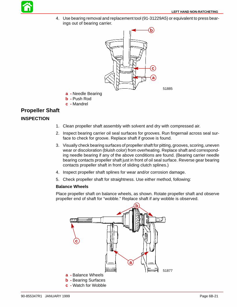
LEFT HAND NON-RATCHETING
90-855347R1 JANUARY 1999 Page 6B-21
4. Use bearing removal and replacement tool (91-31229A5) or equivalent to press bear-ings out of bearing carrier.
51885
a
b
c
a - Needle Bearingb - Push Rodc - Mandrel
Propeller ShaftINSPECTION
1. Clean propeller shaft assembly with solvent and dry with compressed air.
2. Inspect bearing carrier oil seal surfaces for grooves. Run fingernail across seal sur-face to check for groove. Replace shaft if groove is found.
3. Visually check bearing surfaces of propeller shaft for pitting, grooves, scoring, unevenwear or discoloration (bluish color) from overheating. Replace shaft and correspond-ing needle bearing if any of the above conditions are found. (Bearing carrier needlebearing contacts propeller shaft just in front of oil seal surface. Reverse gear bearingcontacts propeller shaft in front of sliding clutch splines.)
4. Inspect propeller shaft splines for wear and/or corrosion damage.
5. Check propeller shaft for straightness. Use either method, following:
Balance Wheels
Place propeller shaft on balance wheels, as shown. Rotate propeller shaft and observepropeller end of shaft for “wobble.” Replace shaft if any wobble is observed.
51877
b
a
c
a - Balance Wheelsb - Bearing Surfacesc - Watch for Wobble

LEFT HAND NON-RATCHETING
Page 6B-22 90-855347R1 JANUARY 1999
“Vee” Blocks and Dial Indicator
Position propeller shaft roller bearing surfaces on vee blocks. Mount a dial indicator atfront edge of propeller splines. Rotate propeller shaft. Dial indicator movement of morethan 0.006 in. (0.152 mm) (or noticeable wobble) is reason for replacement.
DISASSEMBLY
1. Remove shift cam from cam follower.
2. Insert a thin blade screwdriver or awl under first coil of cross pin retainer spring androtate propeller shaft to unwind spring from sliding clutch. DO NOT overstretch spring.
51875
a
a - Cross Pin Retainer Spring
CAUTIONDetent pin is free and can fall out of sliding clutch. Care MUST BE taken not to losepin.
3. Detent pin is free and can be removed from sliding clutch at this time.
4. Push cross pin out of sliding clutch and propeller shaft with a punch.
51875
d
e51879
a
c
b
a - Detent Pinb - Cross Pinc - Sliding Clutchd - Cross Pine - Punch
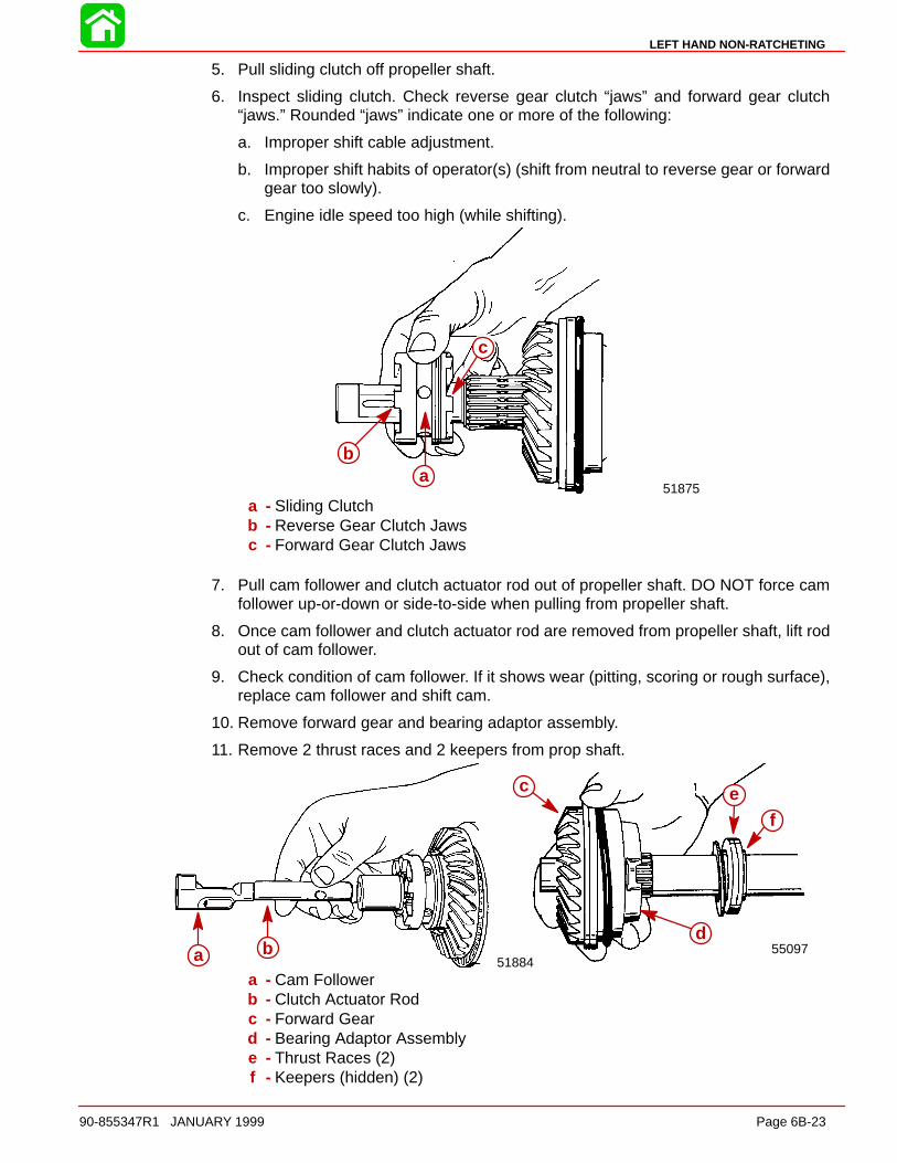
LEFT HAND NON-RATCHETING
90-855347R1 JANUARY 1999 Page 6B-23
5. Pull sliding clutch off propeller shaft.
6. Inspect sliding clutch. Check reverse gear clutch “jaws” and forward gear clutch“jaws.” Rounded “jaws” indicate one or more of the following:
a. Improper shift cable adjustment.
b. Improper shift habits of operator(s) (shift from neutral to reverse gear or forwardgear too slowly).
c. Engine idle speed too high (while shifting).
51875a
b
c
a - Sliding Clutchb - Reverse Gear Clutch Jawsc - Forward Gear Clutch Jaws
7. Pull cam follower and clutch actuator rod out of propeller shaft. DO NOT force camfollower up-or-down or side-to-side when pulling from propeller shaft.
8. Once cam follower and clutch actuator rod are removed from propeller shaft, lift rodout of cam follower.
9. Check condition of cam follower. If it shows wear (pitting, scoring or rough surface),replace cam follower and shift cam.
10. Remove forward gear and bearing adaptor assembly.
11. Remove 2 thrust races and 2 keepers from prop shaft.
55097
c
d
ef
51884a b
a - Cam Followerb - Clutch Actuator Rodc - Forward Geard - Bearing Adaptor Assemblye - Thrust Races (2)f - Keepers (hidden) (2)

LEFT HAND NON-RATCHETING
Page 6B-24 90-855347R1 JANUARY 1999
Clutch Actuator RodCLEANING AND INSPECTION
1. Clean clutch actuator rod in solvent and dry with compressed air.
2. Inspect actuator components for wear or damage. Replace components as required.
Forward Gear and Bearing AdapterDISASSEMBLY/CLEANING/INSPECTION
1. Remove forward gear from bearing adapter.
2. Inspect forward gear clutch teeth for signs of wear. If clutch teeth are worn, slidingclutch should be replaced also.
3. Inspect forward gear teeth for full tooth contact, chips, pits and signs of rust. If forwardgear teeth are damaged, pinion gear must be inspected and replaced if necessary.
4. Inspect forward gear hub for signs of pitting, rust, scoring or discoloration (blueing)due to lack of lubricant.
5. Remove thrust bearing and spacer shim. Inspect thrust bearing for pits, rust, or discol-oration (blueing) due to lack of lubricant.
51878
abc
d
e
f
g
a - Forward Gearb - Forward Gear Clutch Teethc - Forward Gear Teethd - Forward Gear Hube - Thrust Bearingf - Thrust Washerg - Spacer Shim

LEFT HAND NON-RATCHETING
90-855347R1 JANUARY 1999 Page 6B-25
6. Remove thrust washer and O-ring. The thrust washer acts as a bearing surface forthe thrust bearing and it should be inspected for pits, rust, scoring or discoloration dueto lack of lubricant. O-ring should be inspected for cuts or abrasions and replaced ifnecessary.
7. Remove thrust bearing and thrust washer from bearing adaptor. Thrust roller bearingshould be inspected for pitting, rust or signs of discoloration (blueing) due to lack oflubricant. If thrust roller bearing must be replaced, the bearing surfaces on the thrustwasher and propeller shaft where the thrust roller bearing rides should also be in-spected for signs of wear.
55090
c
d
e
55089
a
b
a - Thrust Washerb - O-Ring (hidden)c - Thrust Bearingd - Thrust Washere - Bearing Adaptor
8. The forward gear bearing should be carefully inspected for smoothness of movement,pits, rust, or signs of discoloration (blueing) due to lack of lubricant. If the bearing mustbe replaced, it is recommended that a hammer and cape chisel be used to break thebearing loose from the bearing adapter. Be careful not to damage bearing adapterwhen removing roller bearing.
55091
a
b
a - Forward Gear Bearingb - Bearing Adaptor
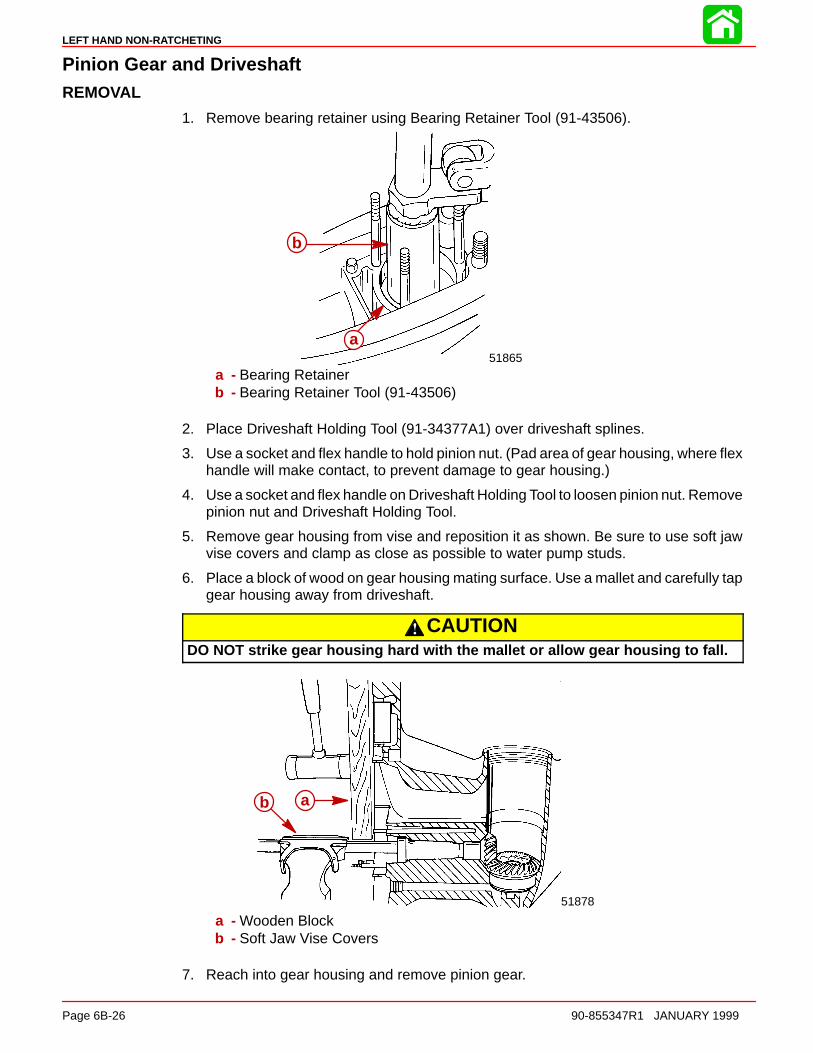
LEFT HAND NON-RATCHETING
Page 6B-26 90-855347R1 JANUARY 1999
Pinion Gear and DriveshaftREMOVAL
1. Remove bearing retainer using Bearing Retainer Tool (91-43506).
51865
a
b
a - Bearing Retainerb - Bearing Retainer Tool (91-43506)
2. Place Driveshaft Holding Tool (91-34377A1) over driveshaft splines.
3. Use a socket and flex handle to hold pinion nut. (Pad area of gear housing, where flexhandle will make contact, to prevent damage to gear housing.)
4. Use a socket and flex handle on Driveshaft Holding Tool to loosen pinion nut. Removepinion nut and Driveshaft Holding Tool.
5. Remove gear housing from vise and reposition it as shown. Be sure to use soft jawvise covers and clamp as close as possible to water pump studs.
6. Place a block of wood on gear housing mating surface. Use a mallet and carefully tapgear housing away from driveshaft.
CAUTIONDO NOT strike gear housing hard with the mallet or allow gear housing to fall.
51878
ab
a - Wooden Blockb - Soft Jaw Vise Covers
7. Reach into gear housing and remove pinion gear.
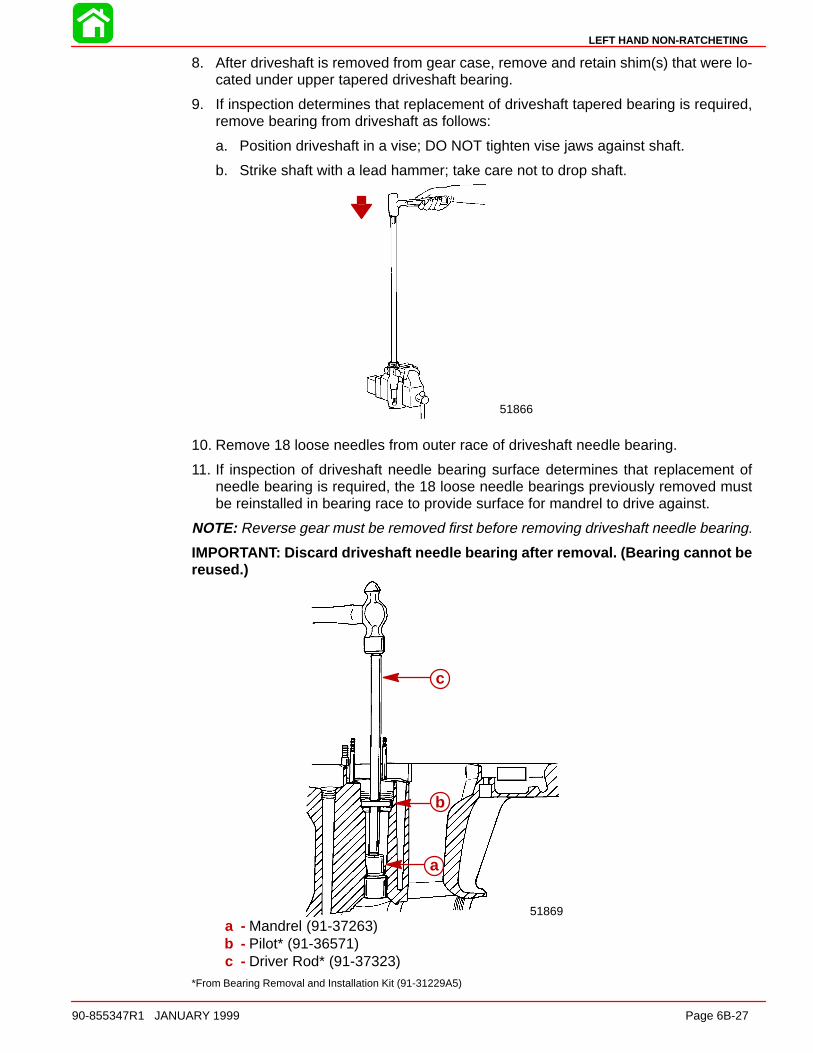
LEFT HAND NON-RATCHETING
90-855347R1 JANUARY 1999 Page 6B-27
8. After driveshaft is removed from gear case, remove and retain shim(s) that were lo-cated under upper tapered driveshaft bearing.
9. If inspection determines that replacement of driveshaft tapered bearing is required,remove bearing from driveshaft as follows:
a. Position driveshaft in a vise; DO NOT tighten vise jaws against shaft.
b. Strike shaft with a lead hammer; take care not to drop shaft.
51866
10. Remove 18 loose needles from outer race of driveshaft needle bearing.
11. If inspection of driveshaft needle bearing surface determines that replacement ofneedle bearing is required, the 18 loose needle bearings previously removed mustbe reinstalled in bearing race to provide surface for mandrel to drive against.
NOTE: Reverse gear must be removed first before removing driveshaft needle bearing.
IMPORTANT: Discard driveshaft needle bearing after removal. (Bearing cannot bereused.)
51869
a
b
c
a - Mandrel (91-37263)b - Pilot* (91-36571)c - Driver Rod* (91-37323)
*From Bearing Removal and Installation Kit (91-31229A5)
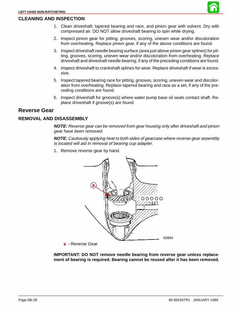
LEFT HAND NON-RATCHETING
Page 6B-28 90-855347R1 JANUARY 1999
CLEANING AND INSPECTION
1. Clean driveshaft, tapered bearing and race, and pinion gear with solvent. Dry withcompressed air. DO NOT allow driveshaft bearing to spin while drying.
2. Inspect pinion gear for pitting, grooves, scoring, uneven wear and/or discolorationfrom overheating. Replace pinion gear, if any of the above conditions are found.
3. Inspect driveshaft needle bearing surface (area just above pinion gear splines) for pit-ting, grooves, scoring, uneven wear and/or discoloration from overheating. Replacedriveshaft and driveshaft needle bearing, if any of the preceding conditions are found.
4. Inspect driveshaft to crankshaft splines for wear. Replace driveshaft if wear is exces-sive.
5. Inspect tapered bearing race for pitting, grooves, scoring, uneven wear and discolor-ation from overheating. Replace tapered bearing and race as a set, if any of the pre-ceding conditions are found.
6. Inspect driveshaft for groove(s) where water pump base oil seals contact shaft. Re-place driveshaft if groove(s) are found.
Reverse GearREMOVAL AND DISASSEMBLY
NOTE: Reverse gear can be removed from gear housing only after driveshaft and piniongear have been removed.
NOTE: Cautiously applying heat to both sides of gearcase where reverse gear assemblyis located will aid in removal of bearing cup adapter.
1. Remove reverse gear by hand.
50884
a
a - Reverse Gear
IMPORTANT: DO NOT remove needle bearing from reverse gear unless replace-ment of bearing is required. Bearing cannot be reused after it has been removed.

LEFT HAND NON-RATCHETING
90-855347R1 JANUARY 1999 Page 6B-29
2. Remove thrust bearing and thrust washer from reverse gear bearing cup.
3. Remove reverse gear bearing adaptor. Remove, measure and make note of the shimthickness and discard (DO NOT reuse) the shims.
50780
50882
de
fg
h
i
a
b
c
a - Thrust Bearingb - Thrust Washerc - Reverse Gear Bearing Adaptord - Bolt (91-31229)e - Nut (91-11-24156)f - Guide Plate (91-816243)g - Washer (91-34961)h - Puller Head (from Slide Hammer Puller Kit 91-34569A1)i - Jaws (91-816242)
CLEANING AND INSPECTION
CAUTIONDO NOT spin bearings dry with compressed air, as this could cause bearing toscore.
1. Clean reverse gear and bearing with solvent and dry with compressed air. DO NOTspin the bearing.
2. Inspect gear teeth for pitting, grooves, scoring, uneven wear and for discoloration(from overheating). Replace gear if any of these conditions are found.
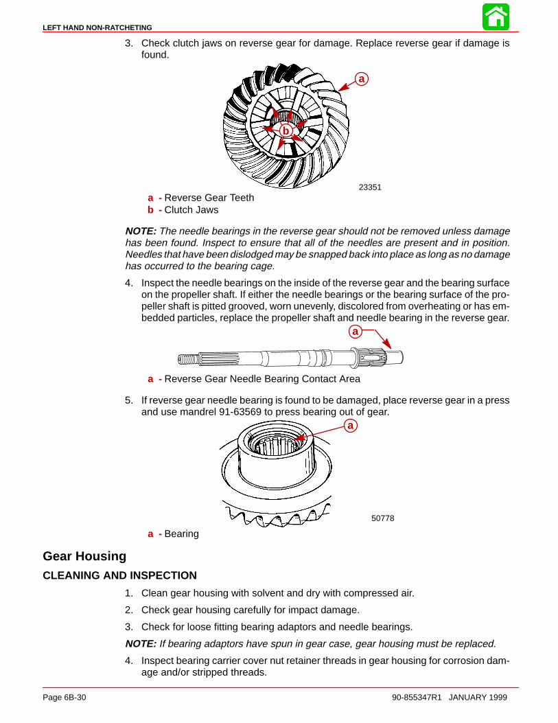
LEFT HAND NON-RATCHETING
Page 6B-30 90-855347R1 JANUARY 1999
3. Check clutch jaws on reverse gear for damage. Replace reverse gear if damage isfound.
23351
b
a
a - Reverse Gear Teethb - Clutch Jaws
NOTE: The needle bearings in the reverse gear should not be removed unless damagehas been found. Inspect to ensure that all of the needles are present and in position.Needles that have been dislodged may be snapped back into place as long as no damagehas occurred to the bearing cage.
4. Inspect the needle bearings on the inside of the reverse gear and the bearing surfaceon the propeller shaft. If either the needle bearings or the bearing surface of the pro-peller shaft is pitted grooved, worn unevenly, discolored from overheating or has em-bedded particles, replace the propeller shaft and needle bearing in the reverse gear.
a
a - Reverse Gear Needle Bearing Contact Area
5. If reverse gear needle bearing is found to be damaged, place reverse gear in a pressand use mandrel 91-63569 to press bearing out of gear.
50778
a
a - Bearing
Gear HousingCLEANING AND INSPECTION
1. Clean gear housing with solvent and dry with compressed air.
2. Check gear housing carefully for impact damage.
3. Check for loose fitting bearing adaptors and needle bearings.
NOTE: If bearing adaptors have spun in gear case, gear housing must be replaced.
4. Inspect bearing carrier cover nut retainer threads in gear housing for corrosion dam-age and/or stripped threads.

LEFT HAND NON-RATCHETING
90-855347R1 JANUARY 1999 Page 6B-31
Reassembly and Installation of Counter Rotation GearHousing
Driveshaft Needle BearingREASSEMBLY/INSTALLATION
CAUTIONIf driveshaft needle bearing failure has occurred, and original bearing race hasturned in the gear housing, gear housing must be replaced. Loose fitting needlebearing will move out of position and cause repeated failures.
NOTE: Driveshaft needle bearing must be installed prior to installation of reverse gear.
1. Apply a thin coat of Quicksilver 2-4-C w/Teflon Lubricant to driveshaft needle bearingbore in gear housing.
2. By way of propeller shaft cavity, place needle bearing in driveshaft bore with num-bered side of bearing facing up driveshaft bore.
3. Install and seat needle bearing with the following tools: Puller Rod* (91-31229), Nut*(91-24156), Pilot* (91-36571), Plate* (91-29310), and Mandrel* (91-92788). Pullbearing up into bore until it bottoms on gear housing shoulder. (DO NOT use exces-sive force.)
*From Bearing Removal and Installation Kit (91-31229A5)
51869a
b
c
d
e
f
a - Mandrelb - Bearingc - Pilotd - Platee - Puller Rodf - Hold
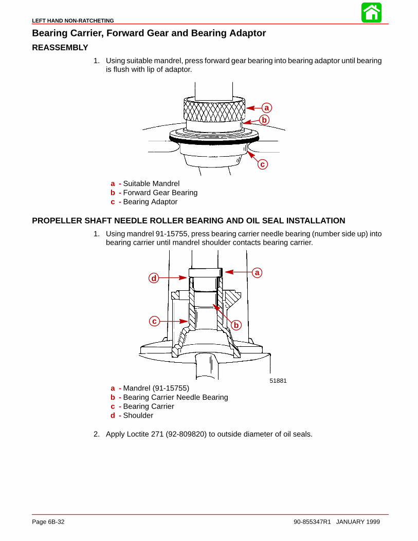
LEFT HAND NON-RATCHETING
Page 6B-32 90-855347R1 JANUARY 1999
Bearing Carrier, Forward Gear and Bearing AdaptorREASSEMBLY
1. Using suitable mandrel, press forward gear bearing into bearing adaptor until bearingis flush with lip of adaptor.
a
b
c
a - Suitable Mandrelb - Forward Gear Bearingc - Bearing Adaptor
PROPELLER SHAFT NEEDLE ROLLER BEARING AND OIL SEAL INSTALLATION
1. Using mandrel 91-15755, press bearing carrier needle bearing (number side up) intobearing carrier until mandrel shoulder contacts bearing carrier.
51881
a
bc
d
a - Mandrel (91-15755)b - Bearing Carrier Needle Bearingc - Bearing Carrierd - Shoulder
2. Apply Loctite 271 (92-809820) to outside diameter of oil seals.
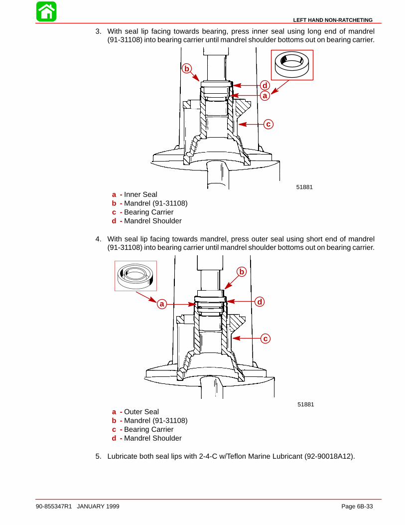
LEFT HAND NON-RATCHETING
90-855347R1 JANUARY 1999 Page 6B-33
3. With seal lip facing towards bearing, press inner seal using long end of mandrel(91-31108) into bearing carrier until mandrel shoulder bottoms out on bearing carrier.
51881
a
b
c
d
a - Inner Sealb - Mandrel (91-31108)c - Bearing Carrierd - Mandrel Shoulder
4. With seal lip facing towards mandrel, press outer seal using short end of mandrel(91-31108) into bearing carrier until mandrel shoulder bottoms out on bearing carrier.
51881
a
b
c
d
a - Outer Sealb - Mandrel (91-31108)c - Bearing Carrierd - Mandrel Shoulder
5. Lubricate both seal lips with 2-4-C w/Teflon Marine Lubricant (92-90018A12).

LEFT HAND NON-RATCHETING
Page 6B-34 90-855347R1 JANUARY 1999
REVERSE GEAR AND BEARING CUP ADAPTOR REASSEMBLY
1. With reverse gear teeth facing down, use mandrel (91-86943) to press propeller shaftneedle bearing (NUMBERS/LETTERS UP) into reverse gear until short shoulder onmandrel bottoms on reverse gear.
NOTE: If gear housing has been replaced or inspection determines that reverse gearbearing adapter must be replaced, assemble and install as follows:
2. Place reverse gear roller bearing (NUMBER/LETTERS UP) in press. Using suitablemandrel, press bearing cup adapter onto reverse gear bearing.
e
f
g
51883
a
b
cd
a - Reverse Gear Teethb - Mandrel (91-86943)c - Propeller Shaft Needle Bearingd - Shouldere - Mandrelf - Bearing Cup Adapterg - Reverse Gear Roller Bearing
IMPORTANT: The appearance of the forward and reverse gear is almost identical.There are two ways to distinguish between the reverse and forward gears. The re-verse gear has a shorter hub and it has a smaller inner diameter needle bearingbore.
50885a b
c
d
a - Reverse Gearb - Forward Gearc - Shorter Length Hubd - Smaller Diameter Bearing Bore

LEFT HAND NON-RATCHETING
90-855347R1 JANUARY 1999 Page 6B-35
Reverse Gear Bearing Adaptor AssemblyINSTALLATION
NOTE: If the reverse gear, reverse gear adaptor, large thrust bearing, or bearing race inthe gear housing were not replaced, install the same shim(s) (or the same thickness ofshim(s)) that were taken out when adaptor was removed. If the reverse gear, reverse gearadaptor, large thrust bearing, bearing race, or gear housing were replaced, install 0.008in. (0.51 mm) of shims.
NOTE: If backlash has already been checked and it has determined that it needs to beadjusted, (see Checking Reverse Gear Backlash), adding 0.001 in. (0.025 mm) shims willreduce the gear backlash by approximately 0.001 in. (0.025 mm). Subtracting 0.001 in.(0.025 mm) shims will increase backlash by approximately the same amount.
Example 1 (if backlash is too high)
Backlash checks:
(subtract) middleof
specification:
You get:
add this quantity of shims:
0.045 in.
0.025 in.
0.020 in.
(1.14 mm)
(0.64 mm)
(0.51 mm)
Example 2 (if backlash is too low)
Backlash checks:
middle of specification:
(subtract) You get:
subtract this quantity of shims:
0.025 in.
0.009 in.
0.016 in.
(0.64 mm)
(0.23 mm)
(0.41 mm)
1. Lubricate the bore into which the reverse gear bearing adaptor is to be installed withQuicksilver Super Duty Gear Lubricant.
2. Place the shim(s) into reverse bore of gear housing.
3. Position the bearing adaptor in the gear housing.
55099
a
b
a - Bearing Adaptorb - Shims

LEFT HAND NON-RATCHETING
Page 6B-36 90-855347R1 JANUARY 1999
4. Position the reverse gear (without the thrust race or thrust bearing) into the gear hous-ing and into the adaptor.
5. Install PILOT RING (91-18603) over DRIVER TOOL (91-18605) and seat pilot ring ingearcase against inner ledge. Thread RETAINER (91-18604) into bearing carrierthreads. Install SCREW (10-18602) into retainer and gently tighten screw againstdriver tool while holding retainer securely. Continue to apply pressure against driverrod until reverse gear/bearing cup adaptor JUST SEATS in gearcase. DO NOTOVER-SEAT the adaptor as the reverse gear bearing will be damaged. As bearingadaptor begins to seat, the effort required to turn screw will increase considerably.
55100
a
b
cd
e
f
a - Reverse Gearb - Pilot Ring (91-18603)c - Driver Tool (91-18605)d - Inner Ledgee - Retainer (91-18604)f - Screw (10-18602)
6. After reverse bearing adaptor is seated, remove screw, retainer, driver tool, pilot ringand reverse gear. Apply Quicksilver Super Duty Gear Lubricant to thrust bearing andinstall thrust race and bearing onto bearing adaptor.
7. Reinstall reverse gear into bearing adaptor.
55102
d
ef
g55101
a
b
c
a - Thrust Bearingb - Thrust Washerc - Bearing Adaptord - Reverse Geare - Thrust Bearingf - Thrust Washer (under thrust bearing)g - Bearing Adaptor
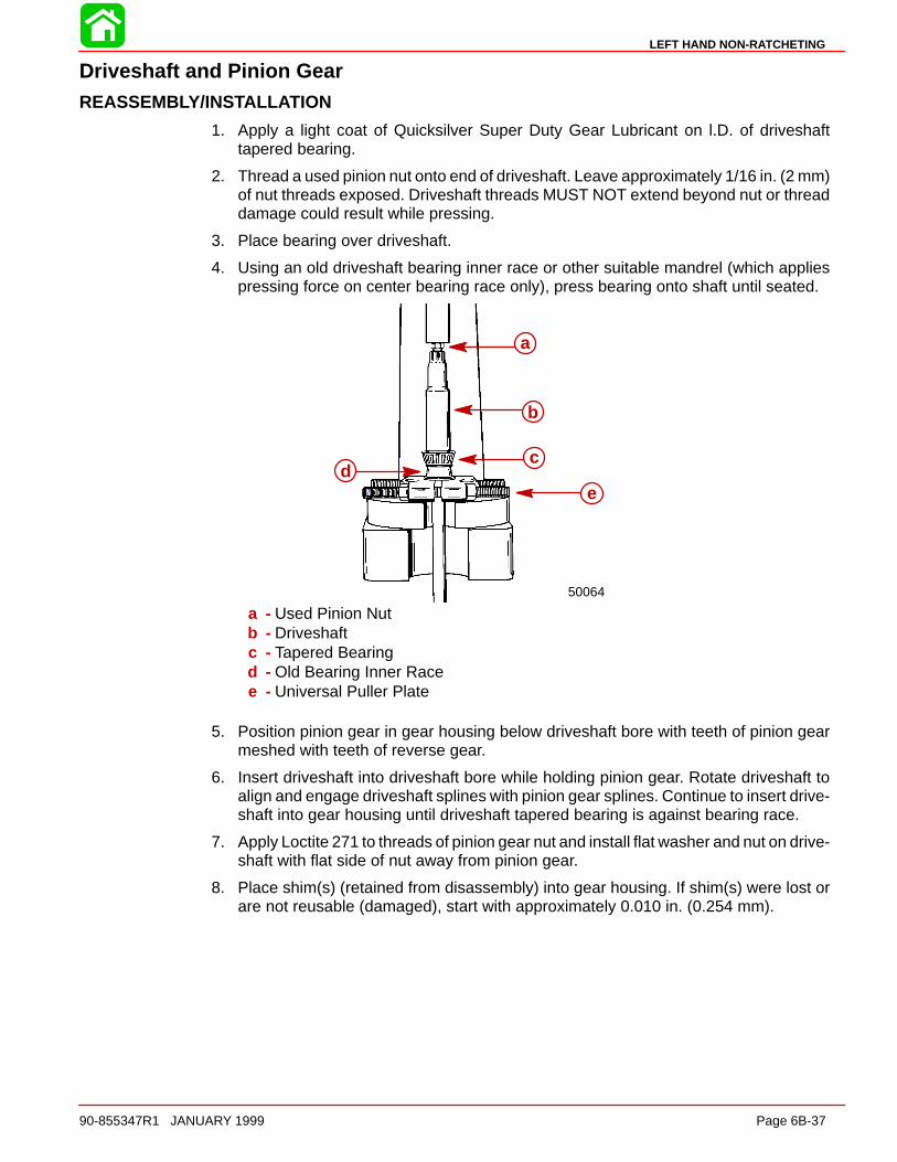
LEFT HAND NON-RATCHETING
90-855347R1 JANUARY 1999 Page 6B-37
Driveshaft and Pinion GearREASSEMBLY/INSTALLATION
1. Apply a light coat of Quicksilver Super Duty Gear Lubricant on l.D. of driveshafttapered bearing.
2. Thread a used pinion nut onto end of driveshaft. Leave approximately 1/16 in. (2 mm)of nut threads exposed. Driveshaft threads MUST NOT extend beyond nut or threaddamage could result while pressing.
3. Place bearing over driveshaft.
4. Using an old driveshaft bearing inner race or other suitable mandrel (which appliespressing force on center bearing race only), press bearing onto shaft until seated.
50064
a
b
cd
e
a - Used Pinion Nutb - Driveshaftc - Tapered Bearingd - Old Bearing Inner Racee - Universal Puller Plate
5. Position pinion gear in gear housing below driveshaft bore with teeth of pinion gearmeshed with teeth of reverse gear.
6. Insert driveshaft into driveshaft bore while holding pinion gear. Rotate driveshaft toalign and engage driveshaft splines with pinion gear splines. Continue to insert drive-shaft into gear housing until driveshaft tapered bearing is against bearing race.
7. Apply Loctite 271 to threads of pinion gear nut and install flat washer and nut on drive-shaft with flat side of nut away from pinion gear.
8. Place shim(s) (retained from disassembly) into gear housing. If shim(s) were lost orare not reusable (damaged), start with approximately 0.010 in. (0.254 mm).
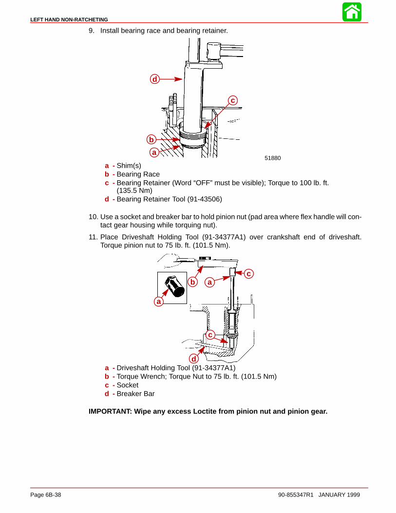
LEFT HAND NON-RATCHETING
Page 6B-38 90-855347R1 JANUARY 1999
9. Install bearing race and bearing retainer.
51880a
b
c
d
a - Shim(s)b - Bearing Racec - Bearing Retainer (Word “OFF” must be visible); Torque to 100 lb. ft.
(135.5 Nm)d - Bearing Retainer Tool (91-43506)
10. Use a socket and breaker bar to hold pinion nut (pad area where flex handle will con-tact gear housing while torquing nut).
11. Place Driveshaft Holding Tool (91-34377A1) over crankshaft end of driveshaft.Torque pinion nut to 75 Ib. ft. (101.5 Nm).
a
b ac
c
da - Driveshaft Holding Tool (91-34377A1)b - Torque Wrench; Torque Nut to 75 lb. ft. (101.5 Nm)c - Socketd - Breaker Bar
IMPORTANT: Wipe any excess Loctite from pinion nut and pinion gear.
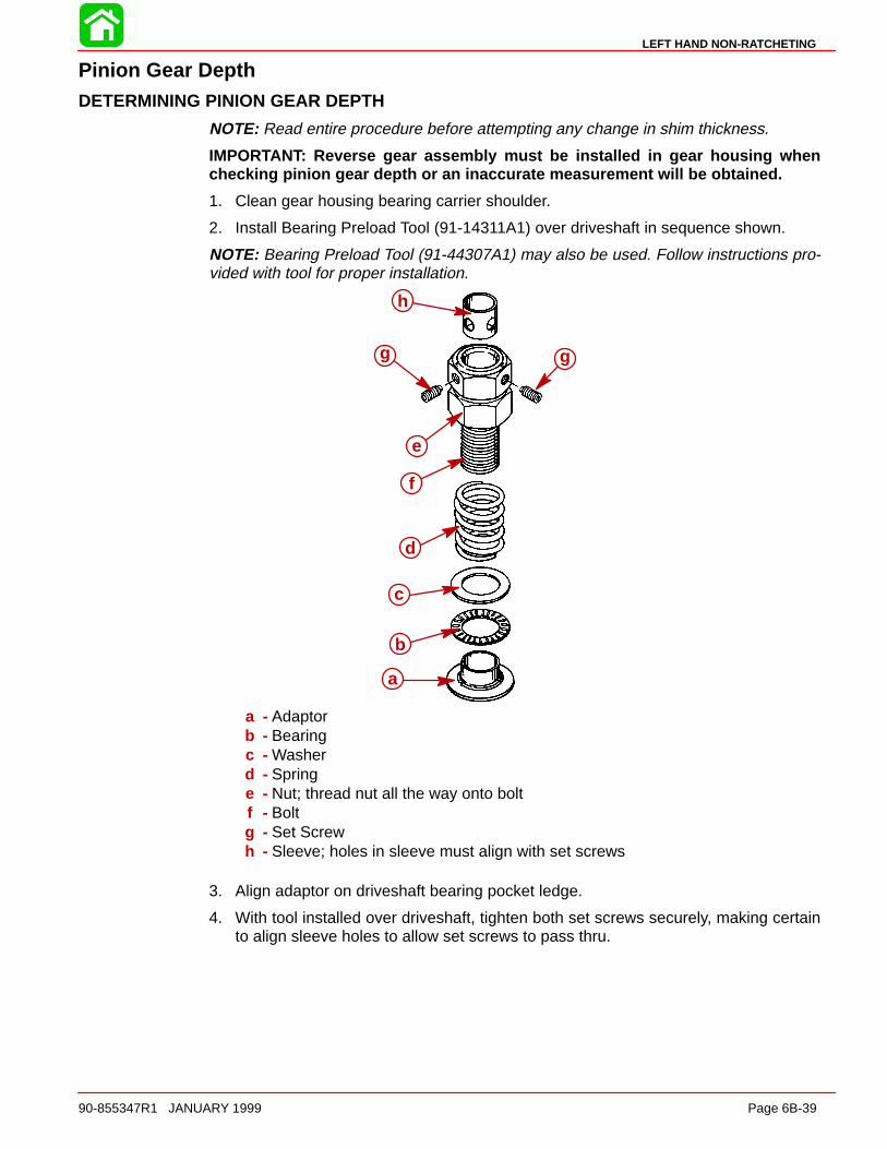
LEFT HAND NON-RATCHETING
90-855347R1 JANUARY 1999 Page 6B-39
Pinion Gear DepthDETERMINING PINION GEAR DEPTH
NOTE: Read entire procedure before attempting any change in shim thickness.
IMPORTANT: Reverse gear assembly must be installed in gear housing whenchecking pinion gear depth or an inaccurate measurement will be obtained.
1. Clean gear housing bearing carrier shoulder.
2. Install Bearing Preload Tool (91-14311A1) over driveshaft in sequence shown.
NOTE: Bearing Preload Tool (91-44307A1) may also be used. Follow instructions pro-vided with tool for proper installation.
a
b
c
d
e
f
g
h
g
a - Adaptorb - Bearingc - Washerd - Springe - Nut; thread nut all the way onto boltf - Boltg - Set Screwh - Sleeve; holes in sleeve must align with set screws
3. Align adaptor on driveshaft bearing pocket ledge.
4. With tool installed over driveshaft, tighten both set screws securely, making certainto align sleeve holes to allow set screws to pass thru.
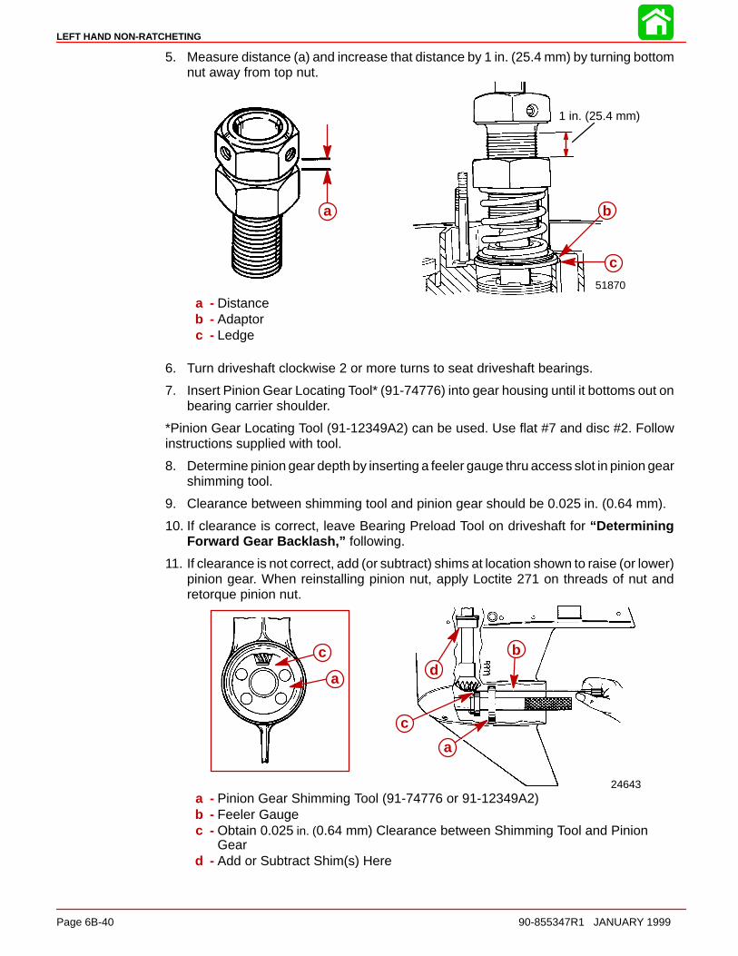
LEFT HAND NON-RATCHETING
Page 6B-40 90-855347R1 JANUARY 1999
5. Measure distance (a) and increase that distance by 1 in. (25.4 mm) by turning bottomnut away from top nut.
1 in. (25.4 mm)
51870
b
c
a
a - Distanceb - Adaptorc - Ledge
6. Turn driveshaft clockwise 2 or more turns to seat driveshaft bearings.
7. Insert Pinion Gear Locating Tool* (91-74776) into gear housing until it bottoms out onbearing carrier shoulder.
*Pinion Gear Locating Tool (91-12349A2) can be used. Use flat #7 and disc #2. Followinstructions supplied with tool.
8. Determine pinion gear depth by inserting a feeler gauge thru access slot in pinion gearshimming tool.
9. Clearance between shimming tool and pinion gear should be 0.025 in. (0.64 mm).
10. If clearance is correct, leave Bearing Preload Tool on driveshaft for “DeterminingForward Gear Backlash,” following.
11. If clearance is not correct, add (or subtract) shims at location shown to raise (or lower)pinion gear. When reinstalling pinion nut, apply Loctite 271 on threads of nut andretorque pinion nut.
c
ad
c
a
b
24643
a
b
a
c
c
d
a - Pinion Gear Shimming Tool (91-74776 or 91-12349A2)b - Feeler Gaugec - Obtain 0.025 in. (0.64 mm) Clearance between Shimming Tool and Pinion
Geard - Add or Subtract Shim(s) Here
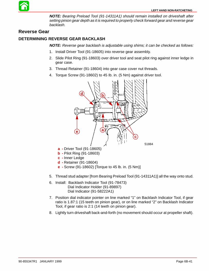
LEFT HAND NON-RATCHETING
90-855347R1 JANUARY 1999 Page 6B-41
NOTE: Bearing Preload Tool (91-14311A1) should remain installed on driveshaft aftersetting pinion gear depth as it is required to properly check forward gear and reverse gearbacklash.
Reverse GearDETERMINING REVERSE GEAR BACKLASH
NOTE: Reverse gear backlash is adjustable using shims; it can be checked as follows:
1. Install Driver Tool (91-18605) into reverse gear assembly.
2. Slide Pilot Ring (91-18603) over driver tool and seat pilot ring against inner ledge ingear case.
3. Thread Retainer (91-18604) into gear case cover nut threads.
4. Torque Screw (91-18602) to 45 Ib. in. (5 Nm) against driver tool.
51884
a
b
c
d
e
a - Driver Tool (91-18605)b - Pilot Ring (91-18603)c - Inner Ledged - Retainer (91-18604)e - Screw (91-18602) [Torque to 45 lb. in. (5 Nm)]
5. Thread stud adapter [from Bearing Preload Tool (91-14311A1)] all the way onto stud.
6. Install: Backlash Indicator Tool (91-78473)Dial Indicator Holder (91-89897)Dial Indicator (91-58222A1)
7. Position dial indicator pointer on line marked “1” on Backlash Indicator Tool, if gearratio is 1.87:1 (15 teeth on pinion gear), or on line marked “2” on Backlash IndicatorTool, if gear ratio is 2:1 (14 teeth on pinion gear).
8. Lightly turn driveshaft back-and-forth (no movement should occur at propeller shaft).
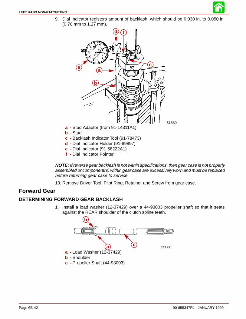
LEFT HAND NON-RATCHETING
Page 6B-42 90-855347R1 JANUARY 1999
9. Dial Indicator registers amount of backlash, which should be 0.030 in. to 0.050 in.(0.76 mm to 1.27 mm).
51880
a
b
c
d
e
f
a - Stud Adaptor (from 91-14311A1)b - Studc - Backlash Indicator Tool (91-78473)d - Dial Indicator Holder (91-89897)e - Dial Indicator (91-58222A1)f - Dial Indicator Pointer
NOTE: If reverse gear backlash is not within specifications, then gear case is not properlyassembled or component(s) within gear case are excessively worn and must be replacedbefore returning gear case to service.
10. Remove Driver Tool, Pilot Ring, Retainer and Screw from gear case.
Forward GearDETERMINING FORWARD GEAR BACKLASH
1. Install a load washer (12-37429) over a 44-93003 propeller shaft so that it seatsagainst the REAR shoulder of the clutch spline teeth.
55088a
b
c
a - Load Washer (12-37429)b - Shoulderc - Propeller Shaft (44-93003)

LEFT HAND NON-RATCHETING
90-855347R1 JANUARY 1999 Page 6B-43
2. Assemble BEARING CARRIER, BEARING ADAPTOR, THRUST WASHER,THRUST BEARING, and FORWARD GEAR onto propeller shaft.
3. Position shim against shoulder in gear case.
55104
g
h
55103
a
b
c
d
e
f
a - Bearing Carrierb - Bearing Adaptorc - Thrust Washerd - Thrust Bearinge - Forward Gearf - Shim (PLACE IN GEARCASE FIRST)g - Shoulderh - Shim
4. Insert entire propeller assembly into gear case.
5. Install tab washer and cover nut. Torque cover nut to 100 Ib. ft. (135.5 N m) to seatforward gear assembly in gear case.
NOTE: Drill a 3/8 in. (22.2 mm) diameter hole through the side (PROPELLER NUT END)of a 5 in. x 2 in. (127 mm x 50.8 mm) long piece of PVC pipe. A screwdriver may be insertedthru pipe into propeller shaft splines to prevent PVC pipe from turning while tightening re-taining nut.
6. Install a 5 in. x 2 in. (127 mm x 50.8 mm) long piece of PVC pipe (obtain locally) overpropeller shaft and secure it against the bearing carrier with a flat washer and nut.
51882
a
b c
d
e
f
g
h
i j k
a - Prop Nutb - Flat Washerc - PVC Pipe [5 in. x 2 in.
(127 mm x 50.8 mm)]d - Cover Nute - Tab Washer
f - Bearing Carrierg - Prop Shafth - Bearing Adaptori - Shimj - Forward Geark - Load Washer
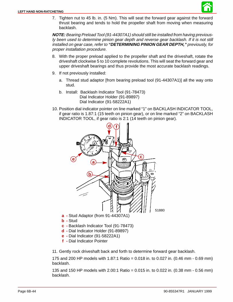
LEFT HAND NON-RATCHETING
Page 6B-44 90-855347R1 JANUARY 1999
7. Tighten nut to 45 lb. in. (5 Nm). This will seat the forward gear against the forwardthrust bearing and tends to hold the propeller shaft from moving when measuringbacklash.
NOTE: Bearing Preload Tool (91-44307A1) should still be installed from having previous-ly been used to determine pinion gear depth and reverse gear backlash. If it is not stillinstalled on gear case, refer to “DETERMINING PINION GEAR DEPTH,” previously, forproper installation procedure.
8. With the proper preload applied to the propeller shaft and the driveshaft, rotate thedriveshaft clockwise 5 to 10 complete revolutions. This will seat the forward gear andupper driveshaft bearings and thus provide the most accurate backlash readings.
9. If not previously installed:
a. Thread stud adaptor [from bearing preload tool (91-44307A1)] all the way ontostud.
b. Install: Backlash Indicator Tool (91-78473)Dial Indicator Holder (91-89897)Dial Indicator (91-58222A1)
10. Position dial indicator pointer on line marked “1” on BACKLASH INDICATOR TOOL,if gear ratio is 1.87:1 (15 teeth on pinion gear), or on line marked “2” on BACKLASHINDICATOR TOOL, if gear ratio is 2:1 (14 teeth on pinion gear).
51880
a
b
c
d
e
f
a - Stud Adaptor (from 91-44307A1)b - Studc - Backlash Indicator Tool (91-78473)d - Dial Indicator Holder (91-89897)e - Dial Indicator (91-58222A1)f - Dial Indicator Pointer
11. Gently rock driveshaft back and forth to determine forward gear backlash.
175 and 200 HP models with 1.87:1 Ratio = 0.018 in. to 0.027 in. (0.46 mm - 0.69 mm)backlash.
135 and 150 HP models with 2.00:1 Ratio = 0.015 in. to 0.022 in. (0.38 mm - 0.56 mm)backlash.
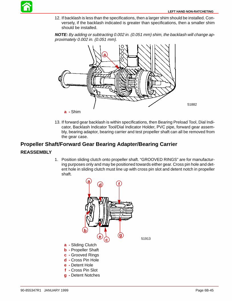
LEFT HAND NON-RATCHETING
90-855347R1 JANUARY 1999 Page 6B-45
12. If backlash is less than the specifications, then a larger shim should be installed. Con-versely, if the backlash indicated is greater than specifications, then a smaller shimshould be installed.
NOTE: By adding or subtracting 0.002 in. (0.051 mm) shim, the backlash will change ap-proximately 0.002 in. (0.051 mm).
51882
a
a - Shim
13. If forward gear backlash is within specifications, then Bearing Preload Tool, Dial Indi-cator, Backlash Indicator Tool/Dial Indicator Holder, PVC pipe, forward gear assem-bly, bearing adaptor, bearing carrier and test propeller shaft can all be removed fromthe gear case.
Propeller Shaft/Forward Gear Bearing Adapter/Bearing CarrierREASSEMBLY
1. Position sliding clutch onto propeller shaft. “GROOVED RINGS” are for manufactur-ing purposes only and may be positioned towards either gear. Cross pin hole and det-ent hole in sliding clutch must line up with cross pin slot and detent notch in propellershaft.
51913
a
b
c
d
e
f
g
a - Sliding Clutchb - Propeller Shaftc - Grooved Ringsd - Cross Pin Holee - Detent Holef - Cross Pin Slotg - Detent Notches

LEFT HAND NON-RATCHETING
Page 6B-46 90-855347R1 JANUARY 1999
2. Place a small amount of Quicksilver 2-4-C w/Teflon Lubricant on actuator rod andinstall cam follower.
ab
a - Actuator Rodb - Cam Follower
3. Slide clutch actuator assembly into propeller shaft. Align cross pin slot in actuator rodwith cross pin slot in clutch/propeller shaft.
51875
a b cd e
a - Cam Followerb - Clutch Actuator Rodc - Propeller Shaftd - Cross Pin Slote - Clutch/Propeller Shaft
4. Insert cross pin through sliding clutch, propeller shaft and actuator rod forcing crosspin tool out.
51875
a
a - Cross Pin
5. Apply a small amount of 2-4-C w/Teflon Marine Lubricant (92-90018A12) to therounded end of detent pin. Position detent pin in detent pin hole of sliding clutch withrounded end of pin toward propeller shaft.
51879
a b
c
a - Detent Pinb - Detent Pin Holec - Sliding Clutch
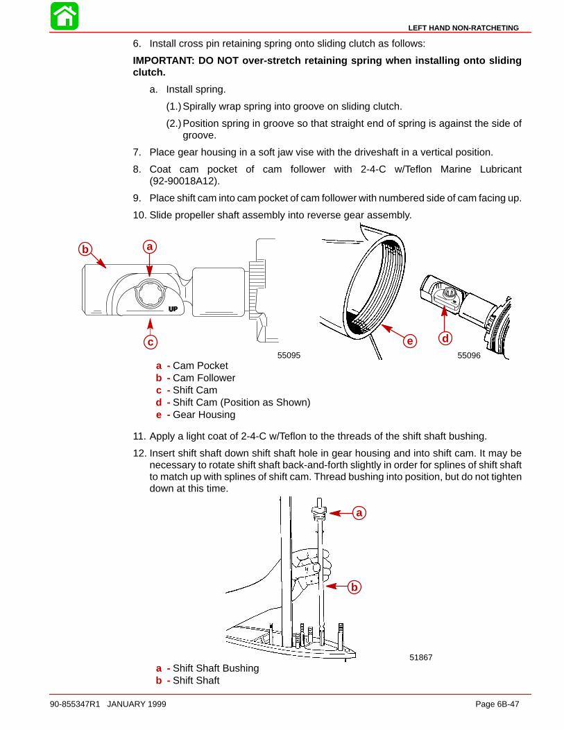
LEFT HAND NON-RATCHETING
90-855347R1 JANUARY 1999 Page 6B-47
6. Install cross pin retaining spring onto sliding clutch as follows:
IMPORTANT: DO NOT over-stretch retaining spring when installing onto slidingclutch.
a. Install spring.
(1.)Spirally wrap spring into groove on sliding clutch.
(2.)Position spring in groove so that straight end of spring is against the side ofgroove.
7. Place gear housing in a soft jaw vise with the driveshaft in a vertical position.
8. Coat cam pocket of cam follower with 2-4-C w/Teflon Marine Lubricant(92-90018A12).
9. Place shift cam into cam pocket of cam follower with numbered side of cam facing up.
10. Slide propeller shaft assembly into reverse gear assembly.
5509655095
de
ab
c
a - Cam Pocketb - Cam Followerc - Shift Camd - Shift Cam (Position as Shown)e - Gear Housing
11. Apply a light coat of 2-4-C w/Teflon to the threads of the shift shaft bushing.
12. Insert shift shaft down shift shaft hole in gear housing and into shift cam. It may benecessary to rotate shift shaft back-and-forth slightly in order for splines of shift shaftto match up with splines of shift cam. Thread bushing into position, but do not tightendown at this time.
51867
a
b
a - Shift Shaft Bushingb - Shift Shaft
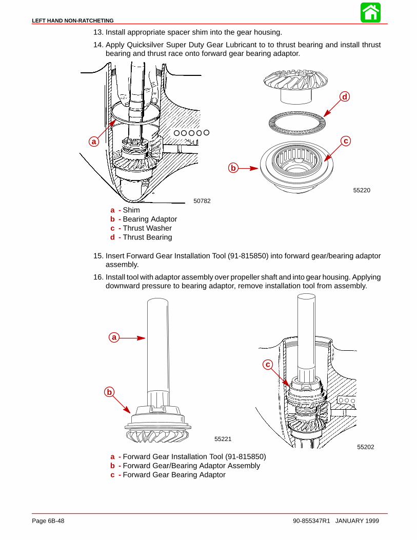
LEFT HAND NON-RATCHETING
Page 6B-48 90-855347R1 JANUARY 1999
13. Install appropriate spacer shim into the gear housing.
14. Apply Quicksilver Super Duty Gear Lubricant to to thrust bearing and install thrustbearing and thrust race onto forward gear bearing adaptor.
b
c
d
a
55220
50782
a - Shimb - Bearing Adaptorc - Thrust Washerd - Thrust Bearing
15. Insert Forward Gear Installation Tool (91-815850) into forward gear/bearing adaptorassembly.
16. Install tool with adaptor assembly over propeller shaft and into gear housing. Applyingdownward pressure to bearing adaptor, remove installation tool from assembly.
5520255221
a
b
c
a - Forward Gear Installation Tool (91-815850)b - Forward Gear/Bearing Adaptor Assemblyc - Forward Gear Bearing Adaptor
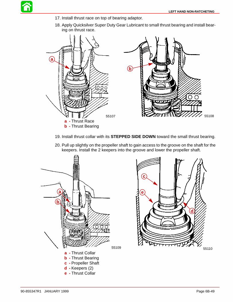
LEFT HAND NON-RATCHETING
90-855347R1 JANUARY 1999 Page 6B-49
17. Install thrust race on top of bearing adaptor.
18. Apply Quicksilver Super Duty Gear Lubricant to small thrust bearing and install bear-ing on thrust race.
5510855107
a
b
a - Thrust Raceb - Thrust Bearing
19. Install thrust collar with its STEPPED SIDE DOWN toward the small thrust bearing.
20. Pull up slightly on the propeller shaft to gain access to the groove on the shaft for thekeepers. Install the 2 keepers into the groove and lower the propeller shaft.
5511055109
c
d
ea
b
a - Thrust Collarb - Thrust Bearingc - Propeller Shaftd - Keepers (2)e - Thrust Collar

LEFT HAND NON-RATCHETING
Page 6B-50 90-855347R1 JANUARY 1999
21. Install second thrust collar with its stepped side UP.
22. Apply Quicksilver Super Duty Gear Lubricant to the second thrust bearing and installit on top of the second thrust collar.
55112
ab
c
a - Thrust Collarb - Thrust Bearingc - Thrust Collar
23. Apply Quicksilver Super Duty Gear Lubricant to to second small thrust bearing raceand install race to the surface inside of the bearing carrier.
24. Apply Quicksilver 2-4-C w/Teflon Marine Lubricant to bearing carrier O-ring. InstallO-ring onto bearing adaptor.
5511350779
a
b
c
a - Thrust Raceb - Bearing Carrier Race Surfacec - O-ring

LEFT HAND NON-RATCHETING
90-855347R1 JANUARY 1999 Page 6B-51
25. Apply Quicksilver 2-4-C w/Teflon Marine Lubricant to:
a. Outer diameter of bearing carrier which contacts gear case.
b. Space between carrier oil seals.
26. Apply Quicksilver Super Duty Gear Lubricant to bearing carrier needle bearing.
27. Install bearing carrier into gear housing.
28. Verify bearing carrier keyway is aligned with gear housing keyway and install bearingcarrier key.
29. Place tab washer against bearing carrier.
51885
55114
ab
a - Bearing Carrierb - Tab Washer
30. Apply 2-4-C w/Teflon to threads of cover nut and install cover nut in gear housing.Verify that the word “OFF” and arrow are visible.
NOTE: Before torquing bearing carrier cover nut, gear case should either be mounted ina stand specifically designed for holding gear cases or bolted to a driveshaft housing toavoid possible damage to the gear case.
31. Using Cover Nut Tool (91-61069), torque cover nut to 210 Ib. ft. (285 Nm).
51911
a b
a - Retainer Nut Tool (91-61069)b - Retainer Nut

LEFT HAND NON-RATCHETING
Page 6B-52 90-855347R1 JANUARY 1999
32. Bend one lock tab of tab washer into cover nut (only one will align).
33. Bend remaining tabs of tab washer toward front of gear housing.
34. Use Shift Shaft Bushing Tool (91-31107) and torque shift shaft bushing to 50 Ib. ft.(68 Nm).
51882
a
b
a - Shift Shaft Bushing Tool (91-31107)b - Shift Shaft Bushing
Water PumpREASSEMBLY/INSTALLATION
1. Install oil seals into water pump base, as follows:
a. Place water pump base on a press.
b. Just before installing each seal apply Loctite 271 on outside diameter of oil seal.
c. With a suitable mandrel, press the smaller diameter oil seal into pump base withlip of oil seal toward impeller side of base.
d. With a suitable mandrel, press the larger diameter oil seal into pump base with lipof oil seal toward gear housing side of base.
e. Wipe any excess Loctite from oil seals and water pump base.
2. Install O-ring into O-ring groove of water pump base. Lubricate O-ring and oil sealswith 2-4-C w/Teflon Marine Lubricant (92-90018A12).
51869
a
bc
a - Mandrelb - Oil Seal (Smaller OD)c - O-Ring Groove

LEFT HAND NON-RATCHETING
90-855347R1 JANUARY 1999 Page 6B-53
3. Install divider block if removed. Use RTV Sealer to seal seams between divider blockand gear housing.
4. Install a new water pump base gasket and install water pump base.
51866
51878
a
b c
d
a - Divider Blockb - Water Pump Basec - Gasketd - Hole (MUST be positioned as shown)
5. Install the following in order: Pump base to face plate gasket, face plate to pump covergasket. Gaskets and face plate are indexed by dowel pin location and must be in-stalled correctly.
b
c
a
51868
a
b
c
a - Gasket (Water Pump Base to Face Plate)b - Face Platec - Gasket (Face Plate to Water Pump Cover)
6. Place impeller drive key on flat of driveshaft. Hold key on driveshaft with a smallamount of Quicksilver 2-4-C w/Teflon Marine Lubricant (92-90018A12).
IMPORTANT: When completing gear housing repair that requires removal of waterpump impeller, it is recommended that the impeller be replaced. If it is necessaryto reuse the impeller, DO NOT install in reverse to original rotation or prematureimpeller failure will occur. Original rotation is clockwise.
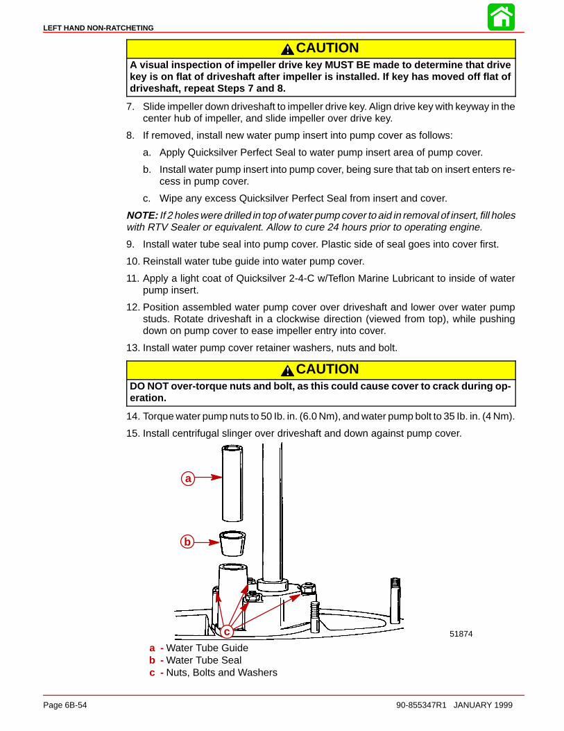
LEFT HAND NON-RATCHETING
Page 6B-54 90-855347R1 JANUARY 1999
CAUTIONA visual inspection of impeller drive key MUST BE made to determine that drivekey is on flat of driveshaft after impeller is installed. If key has moved off flat ofdriveshaft, repeat Steps 7 and 8.
7. Slide impeller down driveshaft to impeller drive key. Align drive key with keyway in thecenter hub of impeller, and slide impeller over drive key.
8. If removed, install new water pump insert into pump cover as follows:
a. Apply Quicksilver Perfect Seal to water pump insert area of pump cover.
b. Install water pump insert into pump cover, being sure that tab on insert enters re-cess in pump cover.
c. Wipe any excess Quicksilver Perfect Seal from insert and cover.
NOTE: If 2 holes were drilled in top of water pump cover to aid in removal of insert, fill holeswith RTV Sealer or equivalent. Allow to cure 24 hours prior to operating engine.
9. Install water tube seal into pump cover. Plastic side of seal goes into cover first.
10. Reinstall water tube guide into water pump cover.
11. Apply a light coat of Quicksilver 2-4-C w/Teflon Marine Lubricant to inside of waterpump insert.
12. Position assembled water pump cover over driveshaft and lower over water pumpstuds. Rotate driveshaft in a clockwise direction (viewed from top), while pushingdown on pump cover to ease impeller entry into cover.
13. Install water pump cover retainer washers, nuts and bolt.
CAUTIONDO NOT over-torque nuts and bolt, as this could cause cover to crack during op-eration.
14. Torque water pump nuts to 50 Ib. in. (6.0 Nm), and water pump bolt to 35 Ib. in. (4 Nm).
15. Install centrifugal slinger over driveshaft and down against pump cover.
51874
a
b
ca - Water Tube Guideb - Water Tube Sealc - Nuts, Bolts and Washers

LEFT HAND NON-RATCHETING
90-855347R1 JANUARY 1999 Page 6B-55
Gear Lubricant Filling Instructions1. Remove any gasket material from “Fill” and “Vent” screws and gear housing.
2. Install new gaskets on “Fill” and “Vent” screws.
IMPORTANT: Never apply lubricant to gear housing without first removing “Vent”screw, or gear housing cannot be filled because of trapped air. Fill gear housingONLY when housing is in a vertical position.
3. Slowly fill housing thru “Fill” hole with Quicksilver Super Duty Lower Unit Lubricant un-til lubricant flows out of “Vent” hole and no air bubbles are visible.
4. Install “Vent” screw into “Vent” hole.
IMPORTANT: DO NOT lose more than one fluid ounce (30cc) of gear lubricant whilereinstalling “Fill” screw.
5. 5. Remove grease tube (or hose) from “Fill” hole and quickly install “Fill” screw into“Fill” hole.
Installing Gear Housing to Driveshaft Housing
WARNINGDisconnect high tension leads from spark plugs and remove spark plugs fromengine before installing gear housing onto driveshaft housing.
1. Tilt engine to full up position and engage the tilt lock lever.
2. Apply a light coat of Quicksilver 2-4-C w/Teflon Marine Lubricant onto driveshaftsplines.
CAUTIONDO NOT allow lubricant on top of driveshaft. Excess lubricant, that is trapped inclearance space, will not allow driveshaft to fully engage with crankshaft. Subse-quently, tightening the gear housing nuts (while excess lubricant is on top of dri-veshaft) will load the driveshaft/crankshaft and damage either or both the power-head and gear housing. Top of driveshaft is to be wiped free of lubricant.
3. Apply a light coat of Quicksilver 2-4-C w/Teflon Marine Lubricant onto shift shaftsplines. (DO NOT allow lubricant on top of shift shaft.)
4. Apply a thin bead of G.E. Silicone Sealer (92-90113--2) against the top of dividerblock.
5. Insert trim tab bolt into hole in rear of gear housing to driveshaft housing machinedsurface.
6. Shift gear housing into forward gear and place guide block anchor pin into forwardgear position.
51900a
a - Guide Block Anchor Pin
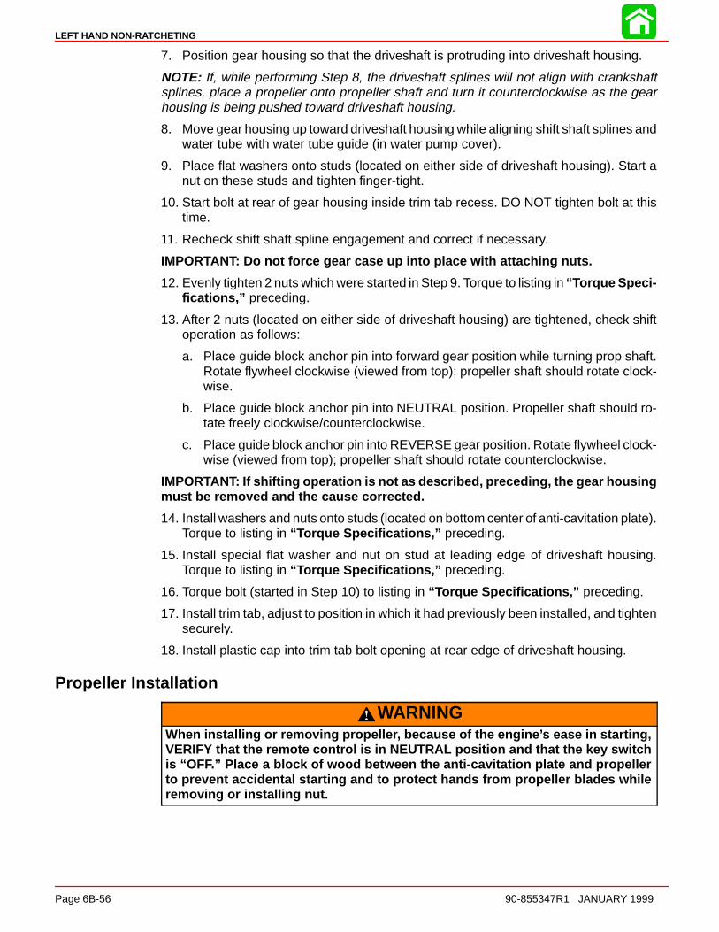
LEFT HAND NON-RATCHETING
Page 6B-56 90-855347R1 JANUARY 1999
7. Position gear housing so that the driveshaft is protruding into driveshaft housing.
NOTE: If, while performing Step 8, the driveshaft splines will not align with crankshaftsplines, place a propeller onto propeller shaft and turn it counterclockwise as the gearhousing is being pushed toward driveshaft housing.
8. Move gear housing up toward driveshaft housing while aligning shift shaft splines andwater tube with water tube guide (in water pump cover).
9. Place flat washers onto studs (located on either side of driveshaft housing). Start anut on these studs and tighten finger-tight.
10. Start bolt at rear of gear housing inside trim tab recess. DO NOT tighten bolt at thistime.
11. Recheck shift shaft spline engagement and correct if necessary.
IMPORTANT: Do not force gear case up into place with attaching nuts.
12. Evenly tighten 2 nuts which were started in Step 9. Torque to listing in “Torque Speci-fications,” preceding.
13. After 2 nuts (located on either side of driveshaft housing) are tightened, check shiftoperation as follows:
a. Place guide block anchor pin into forward gear position while turning prop shaft.Rotate flywheel clockwise (viewed from top); propeller shaft should rotate clock-wise.
b. Place guide block anchor pin into NEUTRAL position. Propeller shaft should ro-tate freely clockwise/counterclockwise.
c. Place guide block anchor pin into REVERSE gear position. Rotate flywheel clock-wise (viewed from top); propeller shaft should rotate counterclockwise.
IMPORTANT: If shifting operation is not as described, preceding, the gear housingmust be removed and the cause corrected.
14. Install washers and nuts onto studs (located on bottom center of anti-cavitation plate).Torque to listing in “Torque Specifications,” preceding.
15. Install special flat washer and nut on stud at leading edge of driveshaft housing.Torque to listing in “Torque Specifications,” preceding.
16. Torque bolt (started in Step 10) to listing in “Torque Specifications,” preceding.
17. Install trim tab, adjust to position in which it had previously been installed, and tightensecurely.
18. Install plastic cap into trim tab bolt opening at rear edge of driveshaft housing.
Propeller Installation
WARNINGWhen installing or removing propeller, because of the engine’s ease in starting,VERIFY that the remote control is in NEUTRAL position and that the key switchis “OFF.” Place a block of wood between the anti-cavitation plate and propellerto prevent accidental starting and to protect hands from propeller blades whileremoving or installing nut.

LEFT HAND NON-RATCHETING
90-855347R1 JANUARY 1999 Page 6B-57
1. To aid in future removal of the propeller, liberally coat the propeller shaft splines withone of the following Quicksilver products:
-- Anti-Corrosion Grease (92-78376A6)-- Special Lubricant 101 (92-13872A1)-- 2-4-C Marine Lubricant (92-90018A12)-- Perfect Seal (92-34227--1)
2. Place forward thrust hub over propeller shaft with shoulder side toward propeller.
3. Place propeller on propeller shaft and slide it up against thrust hub.
a
b
a - Forward Thrust Hubb - Propeller Shaft
4. Place continuity washer (if equipped) onto shoulder of rear thrust hub.
5. Place rear thrust hub, tab washer and propeller nut on propeller shaft.
6. Thread propeller nut onto propeller shaft until nut is recessed into tab washer.
7. After propeller nut is recessed into tab washer, tighten nut securely [minimum of 55Ib. ft. (74.5 Nm) torque].
8. Bend 3 of the tabs of tab washer down in grooves of rear thrust hub to secure propellernut. (If tab washer tabs do not align with slots, continue to tighten propeller nut to ob-tain alignment. DO NOT loosen nut to align tabs.)
CAUTIONDO NOT misinterpret propeller shaft movement with propeller movement. If pro-peller and propeller shaft together move forward-and-aft, this is normal; however,propeller should not move forward-and-aft on propeller shaft.
9. After first use, retighten propeller nut and again secure with tab washer (Steps 7 and8, preceding). Propeller should be checked periodically for tightness, particularly if astainless steel propeller is used.
51916
a
c
d
ba - Continuity Washer (If Equipped)b - Rear Thrust Hubc - Tab Washerd - Propeller Nut
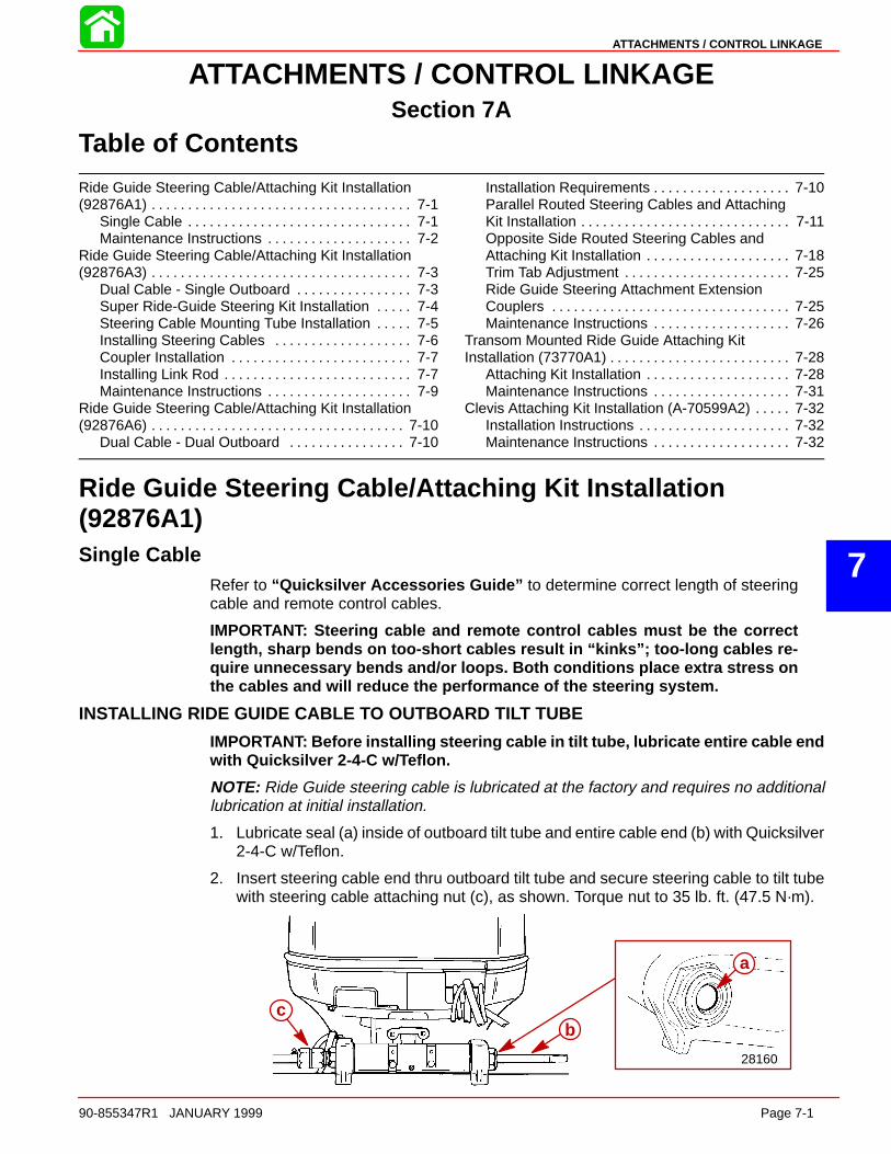
7
ATTACHMENTS / CONTROL LINKAGE
90-855347R1 JANUARY 1999 Page 7-1
ATTACHMENTS / CONTROL LINKAGESection 7A
Table of Contents
Ride Guide Steering Cable/Attaching Kit Installation(92876A1) 7-1. . . . . . . . . . . . . . . . . . . . . . . . . . . . . . . . . . . .
Single Cable 7-1. . . . . . . . . . . . . . . . . . . . . . . . . . . . . . . Maintenance Instructions 7-2. . . . . . . . . . . . . . . . . . . .
Ride Guide Steering Cable/Attaching Kit Installation(92876A3) 7-3. . . . . . . . . . . . . . . . . . . . . . . . . . . . . . . . . . . .
Dual Cable - Single Outboard 7-3. . . . . . . . . . . . . . . . Super Ride-Guide Steering Kit Installation 7-4. . . . . Steering Cable Mounting Tube Installation 7-5. . . . . Installing Steering Cables 7-6. . . . . . . . . . . . . . . . . . . Coupler Installation 7-7. . . . . . . . . . . . . . . . . . . . . . . . . Installing Link Rod 7-7. . . . . . . . . . . . . . . . . . . . . . . . . . Maintenance Instructions 7-9. . . . . . . . . . . . . . . . . . . .
Ride Guide Steering Cable/Attaching Kit Installation(92876A6) 7-10. . . . . . . . . . . . . . . . . . . . . . . . . . . . . . . . . . .
Dual Cable - Dual Outboard 7-10. . . . . . . . . . . . . . . .
Installation Requirements 7-10. . . . . . . . . . . . . . . . . . . Parallel Routed Steering Cables and AttachingKit Installation 7-11. . . . . . . . . . . . . . . . . . . . . . . . . . . . . Opposite Side Routed Steering Cables andAttaching Kit Installation 7-18. . . . . . . . . . . . . . . . . . . . Trim Tab Adjustment 7-25. . . . . . . . . . . . . . . . . . . . . . . Ride Guide Steering Attachment ExtensionCouplers 7-25. . . . . . . . . . . . . . . . . . . . . . . . . . . . . . . . . Maintenance Instructions 7-26. . . . . . . . . . . . . . . . . . .
Transom Mounted Ride Guide Attaching KitInstallation (73770A1) 7-28. . . . . . . . . . . . . . . . . . . . . . . . .
Attaching Kit Installation 7-28. . . . . . . . . . . . . . . . . . . . Maintenance Instructions 7-31. . . . . . . . . . . . . . . . . . .
Clevis Attaching Kit Installation (A-70599A2) 7-32. . . . . Installation Instructions 7-32. . . . . . . . . . . . . . . . . . . . . Maintenance Instructions 7-32. . . . . . . . . . . . . . . . . . .
Ride Guide Steering Cable/Attaching Kit Installation(92876A1)Single Cable
Refer to “Quicksilver Accessories Guide” to determine correct length of steeringcable and remote control cables.
IMPORTANT: Steering cable and remote control cables must be the correctlength, sharp bends on too-short cables result in “kinks”; too-long cables re-quire unnecessary bends and/or loops. Both conditions place extra stress onthe cables and will reduce the performance of the steering system.
INSTALLING RIDE GUIDE CABLE TO OUTBOARD TILT TUBE
IMPORTANT: Before installing steering cable in tilt tube, lubricate entire cable endwith Quicksilver 2-4-C w/Teflon.
NOTE: Ride Guide steering cable is lubricated at the factory and requires no additionallubrication at initial installation.
1. Lubricate seal (a) inside of outboard tilt tube and entire cable end (b) with Quicksilver2-4-C w/Teflon.
2. Insert steering cable end thru outboard tilt tube and secure steering cable to tilt tubewith steering cable attaching nut (c), as shown. Torque nut to 35 lb. ft. (47.5 N·m).
28160
a
bc

ATTACHMENTS / CONTROL LINKAGE
Page 7-2 90-855347R1 JANUARY 1999
STEERING LINK ROD INSTALLATION
IMPORTANT: The steering link rod that connects the steering cable to the enginemust be fastened using special washer head bolt (“a” - Part Number 10-14000) andself locking nuts (“b” & “c” - Part Number 11-34863). These locknuts must neverbe replaced with common nuts (non locking) as they will work loose and vibrateoff freeing the link rod to disengage.
WARNINGDisengagement of a steering link rod can result in the boat taking a full, sudden,sharp turn. This potentially violent action can cause occupants to be thrownoverboard exposing them to serious injury or death.
1. Assemble steering link rod to steering cable with two flat washers (d) and nylon insertlocknut (“b” - Part Number 11-34863). Tighten locknut (b) until it seats, then back nutoff 1/4 turn.
2. Production Outboards - Assemble steering link rod to engine with special washerhead bolt (“a” - Part Number 10-14000) and nylon insert locknut (“c” - Part Number11-34863). First torque bolt (a) to 20 lb. ft. (27 Nm), then torque locknut (c) to 20 lb.ft. (27 Nm).High Performance Outboards - An access hole is provided through the bottom cowlto ease installation of the link rod connecting bolt. Remove the BACK plug for installa-tion and reinstall after installation.
a
b
d
c
WARNINGAfter installation is complete (and before operating outboard), check that boatwill turn right when steering wheel is turned right and that boat will turn left whensteering wheel is turned left. Check steering thru full range (left and right) and atall tilt angles to assure interference-free movement.
Maintenance InstructionsMaintenance inspection is owner’s responsibility and must be performed at intervals spe-cified, following:
Normal Service - Every 50 hrs. of operation or 60 days (whichever comes first)
*Severe Service - Every 25 hrs. of operation or 30 days (whichever comes first)
*Operation in a salt water area is considered “Severe Service.”
1. Carefully check steering system components for wear. Replace worn parts.
2. Check steering system fasteners to be sure that they are torqued to correct specifica-tions.
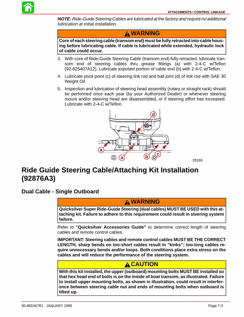
ATTACHMENTS / CONTROL LINKAGE
90-855347R1 JANUARY 1999 Page 7-3
NOTE: Ride-Guide Steering Cables are lubricated at the factory and require no additionallubrication at initial installation.
WARNINGCore of each steering cable (transom end) must be fully retracted into cable hous-ing before lubricating cable. If cable is lubricated while extended, hydraulic lockof cable could occur.
3. With core of Ride-Guide Steering Cable (transom end) fully retracted, lubricate tran-som end of steering cables thru grease fittings (a) with 2-4-C w/Teflon(92-825407A12). Lubricate exposed portion of cable end (b) with 2-4-C w/Teflon.
4. Lubricate pivot point (c) of steering link rod and ball joint (d) of link rod with SAE 30Weight Oil.
5. Inspection and lubrication of steering head assembly (rotary or straight rack) shouldbe performed once each year (by your Authorized Dealer) or whenever steeringmount and/or steering head are disassembled, or if steering effort has increased.Lubricate with 2-4-C w/Teflon.
28169
a
a bc
d
a
acb
d
Ride Guide Steering Cable/Attaching Kit Installation(92876A3)
Dual Cable - Single Outboard
WARNINGQuicksilver Super Ride-Guide Steering (dual cables) MUST BE USED with this at-taching kit. Failure to adhere to this requirement could result in steering systemfailure.
Refer to “Quicksilver Accessories Guide” to determine correct length of steeringcables and remote control cables.
IMPORTANT: Steering cables and remote control cables MUST BE THE CORRECTLENGTH, sharp bends on too-short cables result in “kinks”; too-long cables re-quire unnecessary bends and/or loops. Both conditions place extra stress on thecables and will reduce the performance of the steering system.
CAUTIONWith this kit installed, the upper (outboard) mounting bolts MUST BE installed sothat hex head end of bolts is on the inside of boat transom, as illustrated. Failureto install upper mounting bolts, as shown in illustration, could result in interfer-ence between steering cable nut and ends of mounting bolts when outboard istilted up.
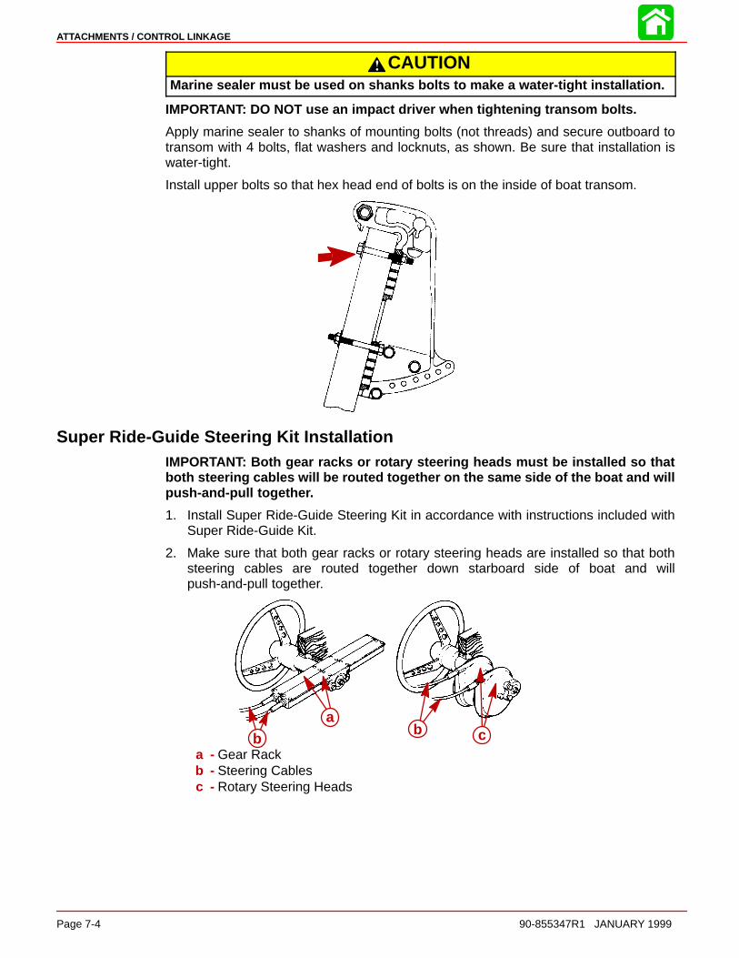
ATTACHMENTS / CONTROL LINKAGE
Page 7-4 90-855347R1 JANUARY 1999
CAUTIONMarine sealer must be used on shanks bolts to make a water-tight installation.
IMPORTANT: DO NOT use an impact driver when tightening transom bolts.
Apply marine sealer to shanks of mounting bolts (not threads) and secure outboard totransom with 4 bolts, flat washers and locknuts, as shown. Be sure that installation iswater-tight.
Install upper bolts so that hex head end of bolts is on the inside of boat transom.
Super Ride-Guide Steering Kit InstallationIMPORTANT: Both gear racks or rotary steering heads must be installed so thatboth steering cables will be routed together on the same side of the boat and willpush-and-pull together.
1. Install Super Ride-Guide Steering Kit in accordance with instructions included withSuper Ride-Guide Kit.
2. Make sure that both gear racks or rotary steering heads are installed so that bothsteering cables are routed together down starboard side of boat and willpush-and-pull together.
ab cb
a - Gear Rackb - Steering Cablesc - Rotary Steering Heads

ATTACHMENTS / CONTROL LINKAGE
90-855347R1 JANUARY 1999 Page 7-5
Steering Cable Mounting Tube InstallationIMPORTANT: Spacers (b) must be installed between outboard swivel bracket andmounting bracket for steering cable mounting tube to provide proper spacing be-tween steering cables.
Secure mounting bracket for steering cable mounting tube on to swivel bracket of out-board.
28163
d
a
c
c
d
b
a - Mounting Bracket for Steering Cable Mounting Tubeb - Spacer (2)c - Locking Retainer (2)d - Bolts (4) - 7/8 in. (22 mm) Long - Torque to 100 lb. in. (11.5 Nm), then Bend
Corner Tabs of Locking Retainers Up and Against Flats on Each Bolt
WARNINGLocking retainer corner tabs, MUST BE bent up and against flats on each bolt thatsecures mounting bracket for steering cable mounting tube to outboard swivelbracket to prevent bolts from turning out.
Install steering cable mounting tube into mounting bracket with 2 adjusting nuts and 2locking tab washers. Verify longer threaded end of tube is toward starboard side of boat.
Temporarily adjust tube so that longer threaded end of tube extends out the same dis-tance as the outboard tilt tube. Do not tighten adjustment nuts at this time.
51891a
b
c
d
a - Steering Cable Mounting Tube (End of Tube with Longer Threads TowardStarboard Side of Boat)
b - Mounting Bracketc - Locking Tab Washers (2)d - Adjustment Nuts (Flats of Nuts Facing Toward Locking Tab Washer)
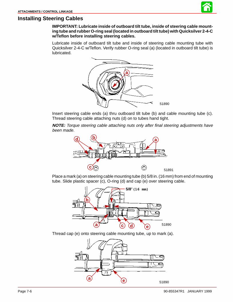
ATTACHMENTS / CONTROL LINKAGE
Page 7-6 90-855347R1 JANUARY 1999
Installing Steering CablesIMPORTANT: Lubricate inside of outboard tilt tube, inside of steering cable mount-ing tube and rubber O-ring seal (located in outboard tilt tube) with Quicksilver 2-4-Cw/Teflon before installing steering cables.
Lubricate inside of outboard tilt tube and inside of steering cable mounting tube withQuicksilver 2-4-C w/Teflon. Verify rubber O-ring seal (a) (located in outboard tilt tube) islubricated.
a
51890
a
Insert steering cable ends (a) thru outboard tilt tube (b) and cable mounting tube (c).Thread steering cable attaching nuts (d) on to tubes hand tight.
NOTE: Torque steering cable attaching nuts only after final steering adjustments havebeen made.
51891
abd
c
Place a mark (a) on steering cable mounting tube (b) 5/8 in. (16 mm) from end of mountingtube. Slide plastic spacer (c), O-ring (d) and cap (e) over steering cable.
5/8″(16 mm)
51890a
b
c d e
Thread cap (e) onto steering cable mounting tube, up to mark (a).
51890a e
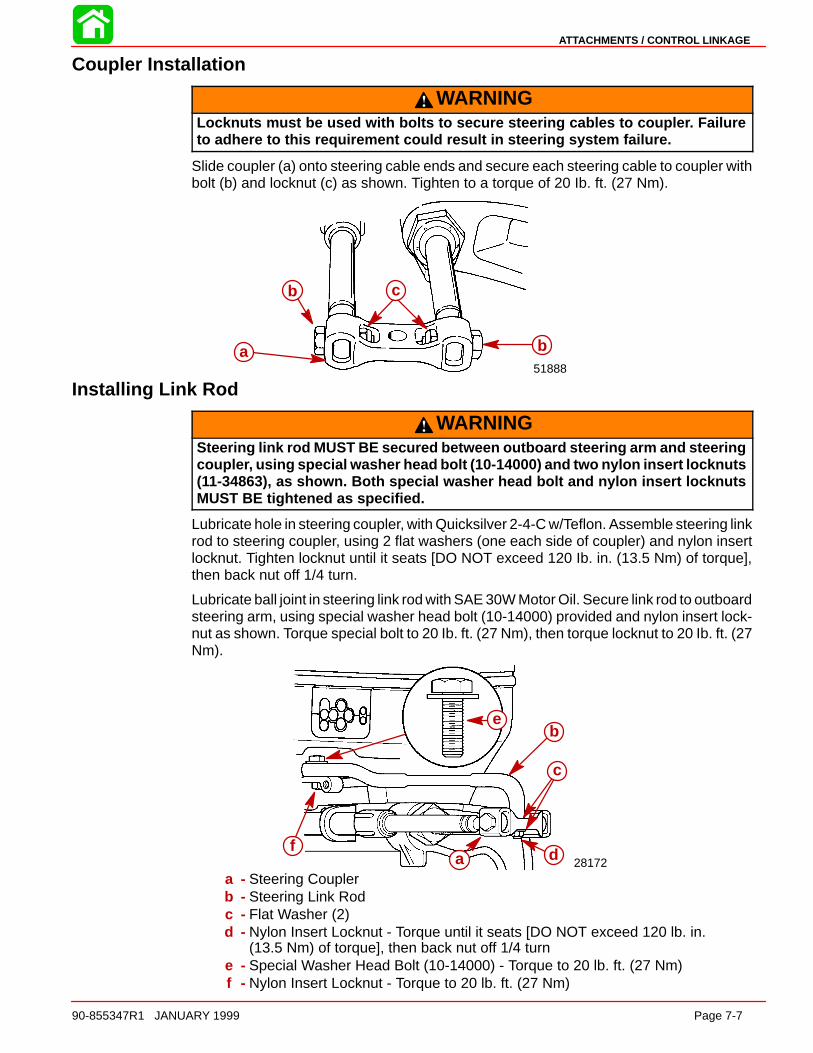
ATTACHMENTS / CONTROL LINKAGE
90-855347R1 JANUARY 1999 Page 7-7
Coupler Installation
WARNINGLocknuts must be used with bolts to secure steering cables to coupler. Failureto adhere to this requirement could result in steering system failure.
Slide coupler (a) onto steering cable ends and secure each steering cable to coupler withbolt (b) and locknut (c) as shown. Tighten to a torque of 20 Ib. ft. (27 Nm).
51888a
b c
b
Installing Link Rod
WARNINGSteering link rod MUST BE secured between outboard steering arm and steeringcoupler, using special washer head bolt (10-14000) and two nylon insert locknuts(11-34863), as shown. Both special washer head bolt and nylon insert locknutsMUST BE tightened as specified.
Lubricate hole in steering coupler, with Quicksilver 2-4-C w/Teflon. Assemble steering linkrod to steering coupler, using 2 flat washers (one each side of coupler) and nylon insertlocknut. Tighten locknut until it seats [DO NOT exceed 120 Ib. in. (13.5 Nm) of torque],then back nut off 1/4 turn.
Lubricate ball joint in steering link rod with SAE 30W Motor Oil. Secure link rod to outboardsteering arm, using special washer head bolt (10-14000) provided and nylon insert lock-nut as shown. Torque special bolt to 20 Ib. ft. (27 Nm), then torque locknut to 20 Ib. ft. (27Nm).
28172a df
b
c
e
a - Steering Couplerb - Steering Link Rodc - Flat Washer (2)d - Nylon Insert Locknut - Torque until it seats [DO NOT exceed 120 lb. in.
(13.5 Nm) of torque], then back nut off 1/4 turne - Special Washer Head Bolt (10-14000) - Torque to 20 lb. ft. (27 Nm)f - Nylon Insert Locknut - Torque to 20 lb. ft. (27 Nm)

ATTACHMENTS / CONTROL LINKAGE
Page 7-8 90-855347R1 JANUARY 1999
STEERING SYSTEM TENSION ADJUSTMENT
IMPORTANT: After this dual steering cable attachment kit is installed, there mustbe proper tension in forward mounted steering cable tor this attachment kit to oper-ate properly. Not enough tension will cause slack (or play) in steering system. Toomuch tension will cause steering cables to bind. Perform the following steps to ad-just for correct tension.
Loosen adjustment nuts and pull steering cable mounting tube (by hand) away from endof steering cable (to remove slack in steering system). Tighten adjustment nuts againstmounting bracket and check system for slack (play.) If steering system is too tight, read-just tube toward end of steering cable or, if too much slack (play) exists in system, readjusttube away from end of steering cable. Tighten nuts against mounting bracket and read-just, if necessary.
51887
b
ac d
a - Steering Cable Mounting Tubeb - Adjustment Nutsc - Adjust Tube in This Direction to Remove Slack from Steering Systemd - Adjust Tube in This Direction to Reduce Tension from Steering System
After steering system tension is adjusted correctly, tighten adjustment nuts againstmounting bracket, to a torque of 35 Ib. ft. (47.5 Nm) and bend a tab lock washer againstflat on each adjustment nut.
51887acc
b
a - Steering Cable Mounting Tubeb - Adjustment Nuts; Torque to 35 lb. ft. (47.5 Nm)c - Tab Lock Washer (Bend Against Flat on Each Adjustment Nut)
Tighten steering cable attaching nuts of each steering cable to a torque of 35 Ib. ft.(47.5 Nm).
51889a
b
a - Cable Attaching Nutb - “V” Groove
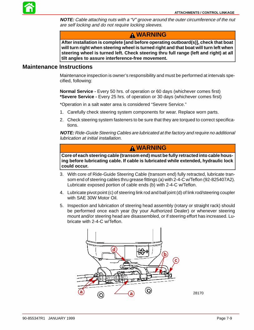
ATTACHMENTS / CONTROL LINKAGE
90-855347R1 JANUARY 1999 Page 7-9
NOTE: Cable attaching nuts with a “V” groove around the outer circumference of the nutare self locking and do not require locking sleeves.
WARNINGAfter installation is complete [and before operating outboard(s)], check that boatwill turn right when steering wheel is turned right and that boat will turn left whensteering wheel is turned left. Check steering thru full range (left and right) at alltilt angles to assure interference-free movement.
Maintenance InstructionsMaintenance inspection is owner’s responsibility and must be performed at intervals spe-cified, following:
Normal Service - Every 50 hrs. of operation or 60 days (whichever comes first)*Severe Service - Every 25 hrs. of operation or 30 days (whichever comes first)
*Operation in a salt water area is considered “Severe Service.”
1. Carefully check steering system components for wear. Replace worn parts.
2. Check steering system fasteners to be sure that they are torqued to correct specifica-tions.
NOTE: Ride-Guide Steering Cables are lubricated at the factory and require no additionallubrication at initial installation.
WARNINGCore of each steering cable (transom end) must be fully retracted into cable hous-ing before lubricating cable. If cable is lubricated while extended, hydraulic lockcould occur.
3. With core of Ride-Guide Steering Cable (transom end) fully retracted, lubricate tran-som end of steering cables thru grease fittings (a) with 2-4-C w/Teflon (92-825407A2).Lubricate exposed portion of cable ends (b) with 2-4-C w/Teflon.
4. Lubricate pivot point (c) of steering link rod and ball joint (d) of link rod/steering couplerwith SAE 30W Motor Oil.
5. Inspection and lubrication of steering head assembly (rotary or straight rack) shouldbe performed once each year (by your Authorized Dealer) or whenever steeringmount and/or steering head are disassembled, or if steering effort has increased. Lu-bricate with 2-4-C w/Teflon.
28170aa
bc
d
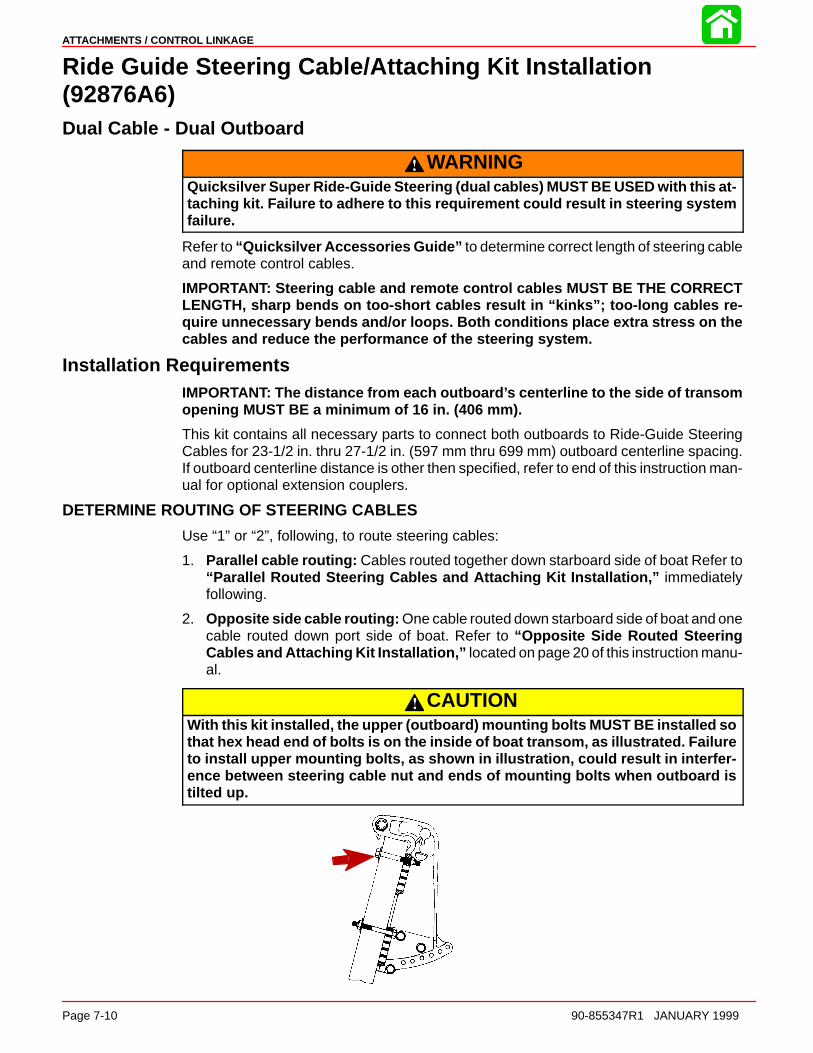
ATTACHMENTS / CONTROL LINKAGE
Page 7-10 90-855347R1 JANUARY 1999
Ride Guide Steering Cable/Attaching Kit Installation(92876A6)Dual Cable - Dual Outboard
WARNINGQuicksilver Super Ride-Guide Steering (dual cables) MUST BE USED with this at-taching kit. Failure to adhere to this requirement could result in steering systemfailure.
Refer to “Quicksilver Accessories Guide” to determine correct length of steering cableand remote control cables.
IMPORTANT: Steering cable and remote control cables MUST BE THE CORRECTLENGTH, sharp bends on too-short cables result in “kinks”; too-long cables re-quire unnecessary bends and/or loops. Both conditions place extra stress on thecables and reduce the performance of the steering system.
Installation RequirementsIMPORTANT: The distance from each outboard’s centerline to the side of transomopening MUST BE a minimum of 16 in. (406 mm).
This kit contains all necessary parts to connect both outboards to Ride-Guide SteeringCables for 23-1/2 in. thru 27-1/2 in. (597 mm thru 699 mm) outboard centerline spacing.If outboard centerline distance is other then specified, refer to end of this instruction man-ual for optional extension couplers.
DETERMINE ROUTING OF STEERING CABLES
Use “1” or “2”, following, to route steering cables:
1. Parallel cable routing: Cables routed together down starboard side of boat Refer to“Parallel Routed Steering Cables and Attaching Kit Installation,” immediatelyfollowing.
2. Opposite side cable routing: One cable routed down starboard side of boat and onecable routed down port side of boat. Refer to “Opposite Side Routed SteeringCables and Attaching Kit Installation,” located on page 20 of this instruction manu-al.
CAUTIONWith this kit installed, the upper (outboard) mounting bolts MUST BE installed sothat hex head end of bolts is on the inside of boat transom, as illustrated. Failureto install upper mounting bolts, as shown in illustration, could result in interfer-ence between steering cable nut and ends of mounting bolts when outboard istilted up.

ATTACHMENTS / CONTROL LINKAGE
90-855347R1 JANUARY 1999 Page 7-11
Install upper bolts so that hex head end of bolts is on the inside of boat transom.
Parallel Routed Steering Cables and Attaching Kit Installation(Both Steering Cables Routed Together Down Starboard Side of Boat)
SUPER RIDE-GUIDE STEERING KIT INSTALLATION
IMPORTANT: Steering cable must be installed into tilt tube of port outboard beforeoutboard is mounted on boat transom.
Both gear racks or rotary steering heads must be installed so that both steeringcables will be routed together on the same side of the boat and will push-and-pulltogether.
1. Install Super Ride-Guide Steering Kit in accordance with instructions included withSuper Ride-Guide Kit.
2. Make sure that both gear racks or rotary steering heads are installed so that bothsteering cables are routed together and will push-and-pull together.
a
b b aa - Straight Rack (Left); Rotary Steering (Right)b - Steering Cables (Install so that Both Cables Will Push and Pull Together)
STEERING CABLE INSTALLATION STARBOARD OUTBOARD
IMPORTANT: Mounting bracket for steering cable mounting tube MUST BE securedto outboard swivel bracket, using 5/8 in. (16 mm) long bolts supplied with this dualcable - dual outboard attaching kit.
Secure mounting bracket for steering cable mounting tube, onto swivel bracket of star-board outboard.
28164a
bcc
a - Mounting Bracket for Steering Cable Mounting Tubeb - Locking Retainers (2)c - Bolts (4) - 5/8 in. (16 mm) Long - Torque to 100 lb. in. (11.5 Nm), then Bend
Corner Tabs of Locking Retainers Up and Against Flats on Each Bolt
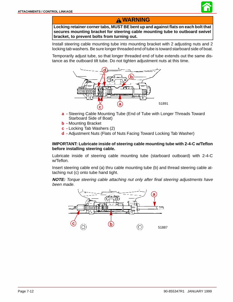
ATTACHMENTS / CONTROL LINKAGE
Page 7-12 90-855347R1 JANUARY 1999
WARNINGLocking retainer corner tabs, MUST BE bent up and against flats on each bolt thatsecures mounting bracket for steering cable mounting tube to outboard swivelbracket, to prevent bolts from turning out.
Install steering cable mounting tube into mounting bracket with 2 adjusting nuts and 2locking tab washers. Be sure longer threaded end of tube is toward starboard side of boat.
Temporarily adjust tube, so that longer threaded end of tube extends out the same dis-tance as the outboard tilt tube. Do not tighten adjustment nuts at this time.
51891a
b
c
d
a - Steering Cable Mounting Tube (End of Tube with Longer Threads TowardStarboard Side of Boat)
b - Mounting Bracketc - Locking Tab Washers (2)d - Adjustment Nuts (Flats of Nuts Facing Toward Locking Tab Washer)
IMPORTANT: Lubricate inside of steering cable mounting tube with 2-4-C w/Teflonbefore installing steering cable.
Lubricate inside of steering cable mounting tube (starboard outboard) with 2-4-Cw/Teflon.
Insert steering cable end (a) thru cable mounting tube (b) and thread steering cable at-taching nut (c) onto tube hand tight.
NOTE: Torque steering cable attaching nut only after final steering adjustments havebeen made.
51887
a
bc

ATTACHMENTS / CONTROL LINKAGE
90-855347R1 JANUARY 1999 Page 7-13
Place a mark (a) on steering cable mounting tube (b) 5/8 in. (16 mm) from end of mountingtube. Slide plastic spacer (c), O-ring (d) and cap (e) over steering cable.
51890
5/8” (16 mm)
a
b
c d e
Thread cap (e) onto steering cable mounting tube, up to mark (a).
51890a e
STEERING CABLE INSTALLATION - PORT OUTBOARD
IMPORTANT: Lubricate inside of port outboard’s tilt tube and rubber O-ring seal lo-cated inside tilt tube with 2-4-C w/Teflon, before installing steering cable.
Lubricate inside of port outboard’s tilt tube and rubber O-ring seal (a) with 2-4-C w/Teflon.
51890
a
Insert steering cable end (b) thru tilt tube (c) of port outboard and thread steering cableattaching nut (d) onto tilt tube hand tight.
NOTE: Torque steering cable attaching nuts only after final steering adjustments havebeen made.
51887
b
cd

ATTACHMENTS / CONTROL LINKAGE
Page 7-14 90-855347R1 JANUARY 1999
STEERING LINK ROD INSTALLATION
WARNINGSteering link rods MUST BE secured between outboard steering arm and steeringcable end, using special washer head bolt (10-14000) and two nylon insert lock-nuts (11-34863), as shown. Both special washer head bolt and nylon insert lock-nuts MUST BE tightened as specified.
50061
28166
e
a
bfd
c
e
a
bfd
c
ab
f
e
a
c
e
d
a - Flat Washer (2 Each Link Rod)b - Nylon Insert Locknut - Torque Until it Seats [DO NOT Exceed 120 lb. in. (13.5
Nm) of Torque], Then Back Off 1/4 Turnc - Special Washer Head Bolt (10-14000) - Torque to 20 lb. ft. (27 Nm)d - Nylon Insert Locknut - Torque to 20 lb. ft. (27 Nm)e - Steering Link Rodf - Steering Cable End
Lubricate holes in ends of steering cables, with Quicksilver 2-4-C w/Teflon Marine Lubri-cant. Assemble steering link rods to steering cable ends of each outboard, using flatwashers and nylon insert locknuts. Tighten locknuts until they seat [DO NOT exceed 120Ib. in. (13.5 Nm) of torque], then back nut off 1/4 turn.
Lubricate ball joints in steering link rods with SAE 30W Motor Oil. Secure link rods to out-board steering arms, using special washer head bolts (10-14000) provided and nylon in-sert locknuts as shown. Torque special bolts to 20 Ib. ft. (27 Nm) then torque locknuts to20 Ib. ft. (27 Nm).

ATTACHMENTS / CONTROL LINKAGE
90-855347R1 JANUARY 1999 Page 7-15
STEERING ARM EXTENSION BRACKET INSTALLATION
Secure a steering arm extension bracket to each out- board’s steering arm.
51889
a
b
cc
d d
a - Steering Arm (Port Outboard Shown)b - Extension Bracketc - Locking Retainer (2 Each Bracket)d - Bolts (2 Each Bracket) 1-1/4 in. (31.8 mm) Long - Torque to 23 lb. ft. (31 Nm),
Then Bend Corner Tabs of Locking Retainers Up Against Flats on Each Bolt
WARNINGLocking retainer corner tabs MUST BE bent up and against flats on each bolt thatsecures extension bracket to outboard steering arm to prevent bolts from turningout.
STEERING COUPLER ASSEMBLY AND INSTALLATION
Position outboards so that they are facing straight forward. (Distance between threadedhole centers of steering arm extensions MUST BE equal to distance between propellershaft centerlines.)
Lubricate inside of rubber sleeves with 2-4-C w/Teflon and slide sleeves on steering cou-pler.
Work rubber bushings onto threaded ends of steering eyes.
Thread jam nut on starboard steering eye.
Thread steering eyes equally into coupler, so that distance between hole centers of steer-ing eye ball joints is equal to distance between threaded hole centers of steering arm ex-tensions. Exposed threads of steering eyes MUST BE of equal length and threads MUSTNOT extend out from coupler more than 2-3/4 in. (70 mm).
50061
c d e b a b d c
a - Couplerb - Rubber Sleevec - Steering Eyed - Rubber Bushinge - Jam Nut
WARNINGBoth steering eyes must be threaded into coupler 3/4 in. (19 mm) minimum.Thread length of steering eye is 3-1/2 in. (89 mm), so exposed thread must notextend out of coupler more than 2-3/4 in. (70 mm). Failure to adhere to this re-quirement could result in steering system failure.

ATTACHMENTS / CONTROL LINKAGE
Page 7-16 90-855347R1 JANUARY 1999
Lubricate ball joint in steering eyes, with SAE 30W Motor Oil.
Assemble steering coupler between outboard steering arm extension brackets, usingspecial washer head bolts (10-14000) provided and nylon insert locknuts as shown.
IMPORTANT: With assembled steering coupler installed and before tightening spe-cial washer head bolts/locknuts, check outboard alignment. Distance betweencenters of special washer head bolts MUST BE equal to distance between propellershaft center lines, for proper steering. It adjustment is necessary, temporarily re-move special washer head bolt/locknut from one steering eye and turn eye in or outto correct alignment.
Torque special washer head bolts to 20 Ib. ft. (27 Nm), then torque locknuts to 20 Ib. ft.(27 Nm).
WARNINGBoth steering eyes MUST BE threaded into coupler 3/4 in. (19 mm) minimum, andjam nut must be tightened against coupler to prevent coupler from turning.Torque “jam” nut to 20 Ib. ft. (27 N·m).
Tighten “jam” nut against coupler. Torque “jam” nut to 20 Ib. ft. (27 Nm).
Spray Quicksilver Corrosion Guard on exposed threads of steering eyes and position rub-ber bushings and rubber sleeves to cover exposed threads of steering eyes.
50061
28167
f a f
g g
f
c
g h
d b
h
f c e a
dc
h
f
a - Couplerb - Rubber Sleevec - Steering Eyed - Rubber Bushinge - Jam Nut - Torque (Against Coupler) to 20 lb. ft. (27 Nm)f - Special Washer Head Bolt (10-14000) - Torque to 20 lb. ft. (27 Nm)g - Nylon Insert Locknut - Torque to 20 lb. ft. (27 Nm)h - Steering Arm Extension Bracket

ATTACHMENTS / CONTROL LINKAGE
90-855347R1 JANUARY 1999 Page 7-17
STEERING SYSTEM TENSION ADJUSTMENT (PARALLEL ROUTED STEERING CABLES)
IMPORTANT: For proper operation of this dual cable - dual outboard steering instal-lation, there MUST BE proper tension in the steering system. NOT ENOUGH ten-sion will cause slack (play) in steering system. TOO MUCH tension will cause steer-ing cables to bind. Perform the following steps to correctly adjust tension.
Loosen adjustment nuts and pull steering cable mounting tube (by hand) away from endof steering cable (to remove slack in steering system). Tighten adjustment nuts againstmounting bracket and check system for slack (play). If steering system is too tight, read-just tube toward end of steering cable or, if too much slack (play) exists in system, readjusttube away from end of steering cable. Tighten nuts against mounting bracket and read-just, if necessary.
51887
ba
c d
a - Steering Cable Mounting Tubeb - Adjustment Nutsc - Adjust Tube in This Direction to Remove Slack from Steering Systemd - Adjust Tube in This Direction to Reduce Tension from Steering System
After steering system tension is adjusted correctly, tighten adjustment nuts againstmounting bracket, to a torque of 35 Ib. ft. (47.5 Nm) and bend a tab lock washer againsta flat on each nut.
51887c c a
b
a - Steering Cable Mounting Tubeb - Adjustment Nuts Torque to 35 lb. ft. (47.5 Nm)c - Tab Lock Washer (Bend Against Flat on Each Adjustment Nut)
Tighten steering cable attaching nuts of each steering cable to a torque of 35 Ib. ft.(47.5 Nm).
51887a
a - Cable Attaching Nut

ATTACHMENTS / CONTROL LINKAGE
Page 7-18 90-855347R1 JANUARY 1999
WARNINGAfter installation is complete [and before operating outboard(s)], check that boatwill turn right when steering wheel is turned right and that boat will turn left whensteering wheel is turned left. Check steering thru full range (left and right) at alltilt angles to assure interference-free movement.
Adjust trim tabs of both outboards, as outlined in “Trim Tab Adjustment” , following.
Opposite Side Routed Steering Cables and Attaching Kit Installation(One Cable Routed down Starboard Side of Boat and One Cable Routed down PortSide of Boat)
SUPER RIDE-GUIDE STEERING KIT INSTALLATION
IMPORTANT: Steering cable must be installed into tilt tube of port outboard beforeoutboard is mounted on boat transom.
Install Super Ride-Guide Steering Kit in accordance with instructions included with SuperRide-Guide Kit.
STEERING CABLE INSTALLATION - STARBOARD OUTBOARD
IMPORTANT: Mounting bracket for steering cable mounting tube MUST BE securedto outboard swivel bracket, using 5/8 in. (16 mm) long bolts supplied with this dualcable - dual outboard attaching kit.
Secure mounting bracket for steering cable mounting tube, onto swivel bracket of star-board outboard.
28164ab
cd d
a - Mounting Bracket for Steering Cable Mounting Tubeb - “J” Clip - Supplied with Outboardc - Locking Retainers (2)d - Bolts (4) - 5/8 in. (16 mm) Long - Torque to 100 lb. in. (11.5 Nm), Then Bend
Corner Tabs of Locking Retainers Up and Against Flats on Each Bolt.
WARNINGLocking retainer corner tabs MUST BE bent up and against flats on each bolt thatsecures mounting bracket for steering cable mounting tube, to prevent boltsfrom turning out.
Install Steering Cable mounting tube into mounting bracket with 2 adjusting nuts and 2locking tab washers. Verify longer threaded end of tube is toward center of boat transom.
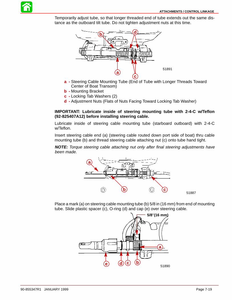
ATTACHMENTS / CONTROL LINKAGE
90-855347R1 JANUARY 1999 Page 7-19
Temporarily adjust tube, so that longer threaded end of tube extends out the same dis-tance as the outboard tilt tube. Do not tighten adjustment nuts at this time.
51891a
b
c
d
a - Steering Cable Mounting Tube (End of Tube with Longer Threads TowardCenter of Boat Transom)
b - Mounting Bracketc - Locking Tab Washers (2)d - Adjustment Nuts (Flats of Nuts Facing Toward Locking Tab Washer)
IMPORTANT: Lubricate inside of steering mounting tube with 2-4-C w/Teflon(92-825407A12) before installing steering cable.
Lubricate inside of steering cable mounting tube (starboard outboard) with 2-4-Cw/Teflon.
Insert steering cable end (a) (steering cable routed down port side of boat) thru cablemounting tube (b) and thread steering cable attaching nut (c) onto tube hand tight.
NOTE: Torque steering cable attaching nut only after final steering adjustments havebeen made.
51887
a
cb
Place a mark (a) on steering cable mounting tube (b) 5/8 in (16 mm) from end of mountingtube. Slide plastic spacer (c), O-ring (d) and cap (e) over steering cable.
5/8″(16 mm)
51890
a
bcde

ATTACHMENTS / CONTROL LINKAGE
Page 7-20 90-855347R1 JANUARY 1999
Thread cap (e) onto steering cable mounting tube, up to mark (a).
51888a
e
STEERING CABLE INSTALLATION - PORT OUTBOARD
IMPORTANT: Lubricate inside of port outboard’s tilt tube and rubber O-ring seal lo-cated inside tilt tube with 2-4-C w/Teflon, before installing steering cable.
Lubricate inside of port outboard’s tilt tube and rubber O-ring seal (a) with 2-4-C w/Teflon.
51890
a
Insert steering cable end (b) (steering cable routed down starboard side of boat) thru tilttube (c) of port outboard and thread steering cable attaching nut (d) onto tilt tube handtight.
NOTE: Torque steering cable attaching nut only after final steering adjustments havebeen made.
51887
b
c
d
STEERING LINK ROD INSTALLATION
WARNINGSteering link rods MUST BE secured between outboard steering arm and steeringcable end, using special washer head bolt (10-14000) and two nylon insert lock-nuts (11-34863), as shown. Both special washer head bolt and nylon insert lock-nuts MUST BE tightened as specified.
Lubricate holes in ends of steering cables, with Quicksilver 2-4-C w/Teflon(92-825407A12). Assemble steering link rods to steering cable ends of each outboard,using flat washers and nylon insert locknuts. Tighten locknuts until they seat [DO NOTexceed 120 lb. in. (13.5 Nm) of torque], then back nut off 1/4 turn.
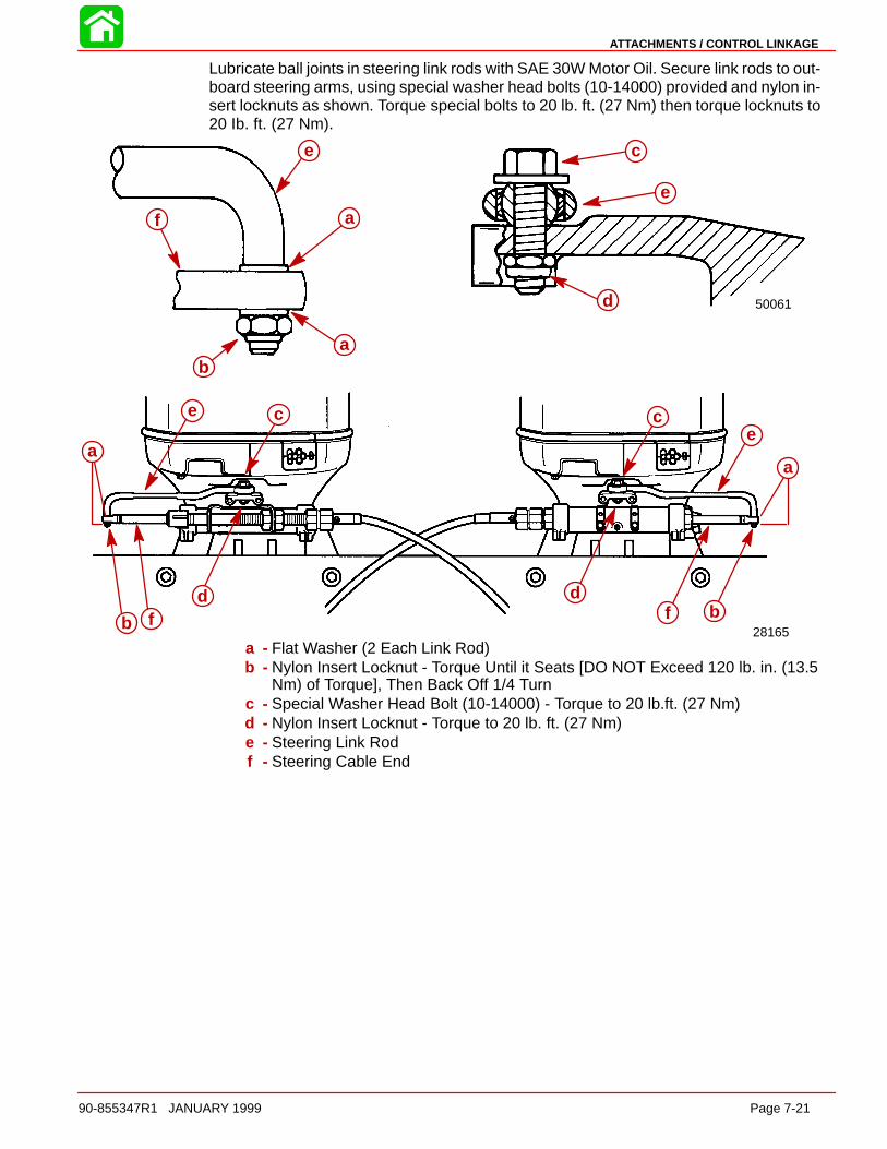
ATTACHMENTS / CONTROL LINKAGE
90-855347R1 JANUARY 1999 Page 7-21
Lubricate ball joints in steering link rods with SAE 30W Motor Oil. Secure link rods to out-board steering arms, using special washer head bolts (10-14000) provided and nylon in-sert locknuts as shown. Torque special bolts to 20 lb. ft. (27 Nm) then torque locknuts to20 Ib. ft. (27 Nm).
50061
28165
ab
f
e
a
c
e
d
aa
b
c
d
e
f bfd
ce
a - Flat Washer (2 Each Link Rod)b - Nylon Insert Locknut - Torque Until it Seats [DO NOT Exceed 120 lb. in. (13.5
Nm) of Torque], Then Back Off 1/4 Turnc - Special Washer Head Bolt (10-14000) - Torque to 20 lb.ft. (27 Nm)d - Nylon Insert Locknut - Torque to 20 lb. ft. (27 Nm)e - Steering Link Rodf - Steering Cable End
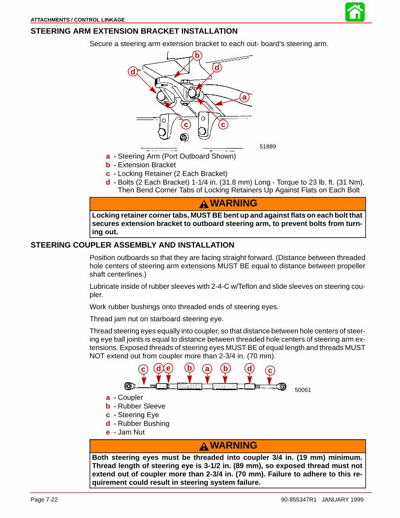
ATTACHMENTS / CONTROL LINKAGE
Page 7-22 90-855347R1 JANUARY 1999
STEERING ARM EXTENSION BRACKET INSTALLATION
Secure a steering arm extension bracket to each out- board’s steering arm.
51889
b
a
cc
d d
a - Steering Arm (Port Outboard Shown)b - Extension Bracketc - Locking Retainer (2 Each Bracket)d - Bolts (2 Each Bracket) 1-1/4 in. (31.8 mm) Long - Torque to 23 lb. ft. (31 Nm),
Then Bend Corner Tabs of Locking Retainers Up Against Flats on Each Bolt
WARNINGLocking retainer corner tabs, MUST BE bent up and against flats on each bolt thatsecures extension bracket to outboard steering arm, to prevent bolts from turn-ing out.
STEERING COUPLER ASSEMBLY AND INSTALLATION
Position outboards so that they are facing straight forward. (Distance between threadedhole centers of steering arm extensions MUST BE equal to distance between propellershaft centerlines.)
Lubricate inside of rubber sleeves with 2-4-C w/Teflon and slide sleeves on steering cou-pler.
Work rubber bushings onto threaded ends of steering eyes.
Thread jam nut on starboard steering eye.
Thread steering eyes equally into coupler, so that distance between hole centers of steer-ing eye ball joints is equal to distance between threaded hole centers of steering arm ex-tensions. Exposed threads of steering eyes MUST BE of equal length and threads MUSTNOT extend out from coupler more than 2-3/4 in. (70 mm).
50061
c d e b a b d c
a - Couplerb - Rubber Sleevec - Steering Eyed - Rubber Bushinge - Jam Nut
WARNINGBoth steering eyes must be threaded into coupler 3/4 in. (19 mm) minimum.Thread length of steering eye is 3-1/2 in. (89 mm), so exposed thread must notextend out of coupler more than 2-3/4 in. (70 mm). Failure to adhere to this re-quirement could result in steering system failure.

ATTACHMENTS / CONTROL LINKAGE
90-855347R1 JANUARY 1999 Page 7-23
Lubricate ball joint in steering eyes with SAE 30W Motor Oil.
Assemble steering coupler between outboard steering arm extension brackets, usingspecial washer head bolts (10-14000) provided and nylon insert locknuts, as shown.
IMPORTANT: With assembled steering coupler installed and before tightening spe-cial washer head bolts/locknuts, check outboard alignment. Distance betweencenters of special washer head bolts MUST BE equal to distance between propellershaft center lines, for proper steering. If adjustment is necessary, temporarily re-move special washer head bolt/locknut from one steering eye and turn eye in or outto correct alignment.
Torque special washer head bolts to 20 Ib. ft. (27 Nm), then torque locknuts to 20 Ib. ft.(27 Nm).
WARNINGBoth steering eyes MUST BE threaded into coupler 3/4 in. (19 mm) minimum, andjam nut must be tightened against coupler to prevent coupler from turning.Torque “jam” nut to 20 Ib. ft. (27 Nm).
Tighten “jam” nut against coupler. Torque “jam” nut to 20 Ib. ft. (27 Nm).
Spray Quicksilver Corrosion Guard on exposed threads of steering eyes and position rub-ber bushings and rubber sleeves to cover exposed threads of steering eyes.
50061
50061
28174
af f
g g
a
bd dc
c ef
h
f
h
g h
cf
a - Couplerb - Rubber Sleevec - Steering Eyed - Rubber Bushinge - Jam Nut - Torque
(Against Coupler) to 20lb. ft. (27 Nm)
f - Special Washer Head Bolt(10-14000) - Torque to 20 lb. ft.(27 Nm)
g - Nylon Insert Locknut - Torqueto 20 lb. ft. (27 Nm)
h - Steering Arm Extension Bracket

ATTACHMENTS / CONTROL LINKAGE
Page 7-24 90-855347R1 JANUARY 1999
STEERING SYSTEM TENSION ADJUSTMENT (PARALLEL ROUTED STEERING CABLES)
IMPORTANT: For proper operation of this dual cable - dual outboard steering instal-lation, there MUST BE proper tension in the steering system. NOT ENOUGH ten-sion will cause slack (play) in steering system. TOO MUCH tension will cause steer-ing cables to bind. Perform the following steps to correctly adjust tension.
Loosen adjustment nuts and pull steering cable mounting tube (by hand) away from endof steering cable (to remove slack in steering system). Tighten adjustment nuts againstmounting bracket and check system for slack (play). If steering system is too tight, read-just tube toward end of steering cable or, if too much slack (play) exists in system, readjusttube away from end of steering cable. Tighten nuts against mounting bracket and read-just, if necessary.
51887
ab
cda - Steering Cable Mounting Tubeb - Adjustment Nutsc - Adjust Tube in This Direction to Remove Slack from Steering Systemd - Adjust Tube in This Direction to Reduce Tension from Steering System
After steering system tension is adjusted correctly, tighten adjustment nuts againstmounting bracket to a torque of 35 Ib. ft. (47.5 Nm) and bend a tab lock washer againsta flat on each nut.
51887c c a
b
a - Steering Cable Mounting Tubeb - Adjustment Nuts; Torque to 35 lb. ft. (47.5 Nm)c - Tab Lock Washer (Bend Against Flat on Each Adjustment Nut)
Tighten steering cable attaching nuts of each steering cable to a torque of 35 Ib. ft. (47.5Nm).
NOTE: Cable attaching nuts with a “V” groove around outer circumference are self lockingand do not require locking sleeves.
WARNINGAfter installation is complete [and before operating outboard(s)], check that boatwill turn right when steering wheel is turned right and that boat will turn left whensteering wheel is turned left. Check steering thru full range (left and right) at alltilt angles to assure interference-free movement.
Adjust trim tabs of both outboards, as outlined in “Trim Tab Adjustment,” following.

ATTACHMENTS / CONTROL LINKAGE
90-855347R1 JANUARY 1999 Page 7-25
Trim Tab AdjustmentDUAL OUTBOARD - COUNTER ROTATION INSTALLATION
1. Shift outboard into neutral and make sure ignition key is at “OFF” position.
2. Remove plastic cap from rear of driveshaft housing and loosen bolt and trim tab.
3. Position trim tabs of both outboards straight to rear of outboard, so that tabs arealigned with gear housing centerline.
4. Tighten both trim tab bolts securely and replace plastic caps. No further adjustmentwill be required.
DUAL OUTBOARD - NON COUNTER ROTATION INSTALLATION
1. Check trim tab position as follows:
IMPORTANT: Initial trim tab setting for both outboards should be straight to rearof outboard, so that tabs are aligned with gear housing center line. Refer to “If nec-essary, adjust trim tab as follows,” following.
a. Operate boat at normal cruise throttle setting and adjust trim to optimum setting.
b. If boat pulls to the right (starboard), trailing edge of trim tab must be moved to theright (when viewing outboard from behind). If boat pulls to the left (port), trailingedge of trim tab must be moved to the left.
2. If necessary, adjust trim tab as follows:
a. Shift outboard into NEUTRAL and make sure ignition key is at “OFF” position.
b. Remove plastic cap from rear of driveshaft housing and loosen bolt and trim tab.
IMPORTANT: Trim tabs MUST BE set in the same position on both outboards.
c. If boat pulls to the right, adjust trailing edges of both trim tabs to the right. If boatpulls to the left, adjust trailing edges of both trim tabs to the left.
d. Tighten both trim tab bolts securely and replace plastic caps.
e. Operate boat per “Check trim tab position as follows,” preceding, to check trimtab setting. Readjust trim tabs, if necessary.
Ride Guide Steering Attachment Extension CouplersListed below are typical couplers available. Refer to the current Quicksilver AccessoryGuide for specific coupler lengths and part numbers.
Outboard Center Line Distance Required Coupler(s) Between Steering Eyes
22-1/2 in. thru 24-1/2 in. 12″ (305 mm) Coupler(572 mm thru 622 mm)
23-1/2 in. thru 27-1/2 in. 15″ (381 mm) Coupler (Supplied with this kit)(597 mm thru 699 mm)
26-1/2 in. thru 30-1/2 in. 18″ (457 mm) Coupler(673 mm thru 755 mm)
30 in. thru 34 in. 9″ (229 mm) Coupler and 12″ (305 mm) Coupler(763 mm thru 864 mm) (Connected together with coupler link rod)
33 in. thru 37 in. 12″ (305 mm) Coupler and 12″ (305 mm) Coupler(838 mm thru 940 mm) (Connected together with coupler link rod)

ATTACHMENTS / CONTROL LINKAGE
Page 7-26 90-855347R1 JANUARY 1999
WARNINGWhen 2 couplers are connected together with coupler link rod, a lock washermust be used on each side of coupler link rod, and link rod must be torqued to20 Ib. ft. (27 N·m) into end of each coupler.
51890
a b a
c
a - Couplers Connected Togetherb - Lock washersc - Coupler Link Rod [Torque to 20 lb. ft. (27 Nm) into End of Each Coupler]
Maintenance InstructionsMaintenance inspection is owner’s responsibility and must be performed at intervals spe-cified, following:
Normal Service - Every 50 hrs. of operation or 60 days (whichever comes first)
*Severe Service - Every 25 hrs. of operation or 30 days (whichever comes first)
*Operation in a salt water area is considered “Severe Service.”
1. Carefully check steering system components for wear. Replace worn parts.
2. Check steering system fasteners to be sure that they are torqued to correct specifica-tions.
NOTE: Ride-Guide Steering Cables are lubricated at the factory and require no additionallubrication at initial installation.
WARNINGCore of each steering cable (transom end) must be fully retracted into cable hous-ing before lubricating cable. If cable is lubricated while extended, hydraulic lockof cable could occur.
3. With core of Ride-Guide Steering Cable (transom end) fully retracted, lubricate tran-som end of steering cables thru grease fittings with 2-4-C w/Teflon (92-825407A12).Lubricate exposed portion of cable ends with 2-4-C w/Teflon.
4. Lubricate pivot points of steering link rods and ball joints of link rods/steering couplerwith SAE 30W Motor Oil.

ATTACHMENTS / CONTROL LINKAGE
90-855347R1 JANUARY 1999 Page 7-27
5. Inspection and lubrication of steering head assembly (rotary or straight rack) shouldbe performed once each year (by your Authorized Dealer) or whenever steeringmount and/or steering head are disassembled, or if steering effort has increased. Lu-bricate with 2-4-C w/Teflon.
28168a
a
b
c
d
a ab
c
d
Lubrication Points for Parallel Cable Routing Installations
28175a a a a b
c
d
b
c
d
Lubrication Points for Opposite Side Cable Routing Installationsa - Grease Fittingsb - Cable Endsc - Pivot Pointsd - Ball Joints
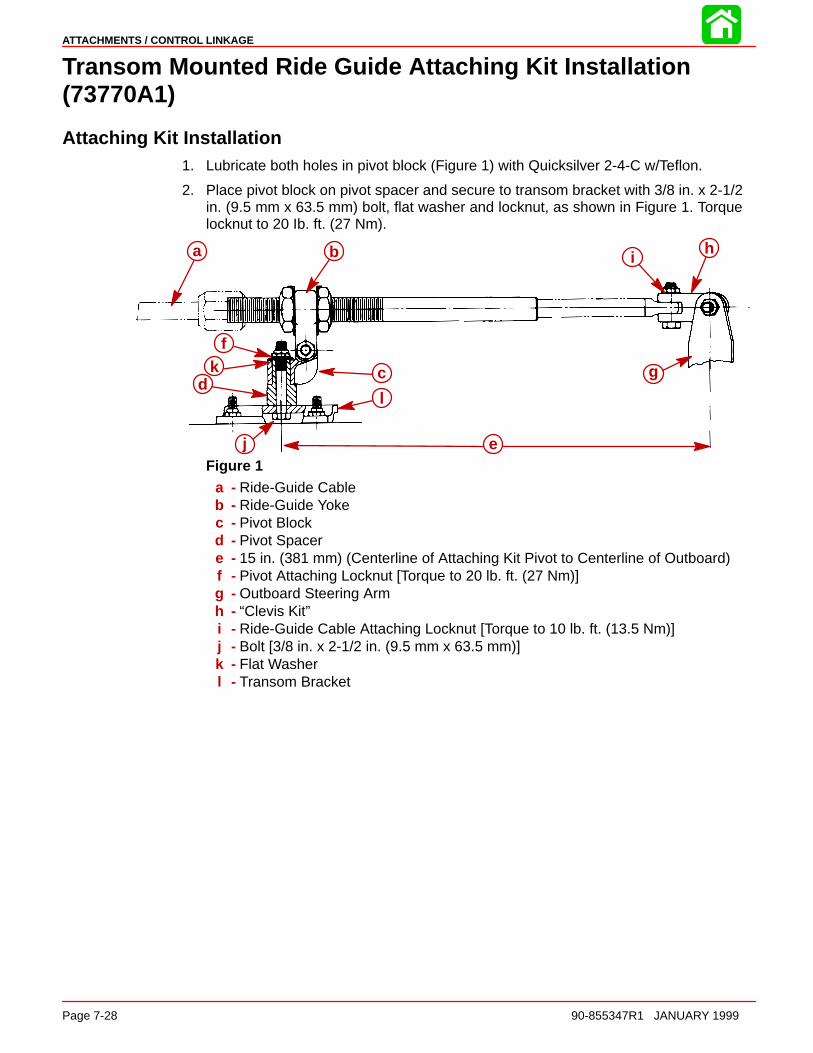
ATTACHMENTS / CONTROL LINKAGE
Page 7-28 90-855347R1 JANUARY 1999
Transom Mounted Ride Guide Attaching Kit Installation(73770A1)
Attaching Kit Installation1. Lubricate both holes in pivot block (Figure 1) with Quicksilver 2-4-C w/Teflon.
2. Place pivot block on pivot spacer and secure to transom bracket with 3/8 in. x 2-1/2in. (9.5 mm x 63.5 mm) bolt, flat washer and locknut, as shown in Figure 1. Torquelocknut to 20 Ib. ft. (27 Nm).
a b
cd
e
f
g
hi
j
k
l
Figure 1a - Ride-Guide Cableb - Ride-Guide Yokec - Pivot Blockd - Pivot Spacere - 15 in. (381 mm) (Centerline of Attaching Kit Pivot to Centerline of Outboard)f - Pivot Attaching Locknut [Torque to 20 lb. ft. (27 Nm)]g - Outboard Steering Armh - “Clevis Kit”i - Ride-Guide Cable Attaching Locknut [Torque to 10 lb. ft. (13.5 Nm)]j - Bolt [3/8 in. x 2-1/2 in. (9.5 mm x 63.5 mm)]k - Flat Washerl - Transom Bracket
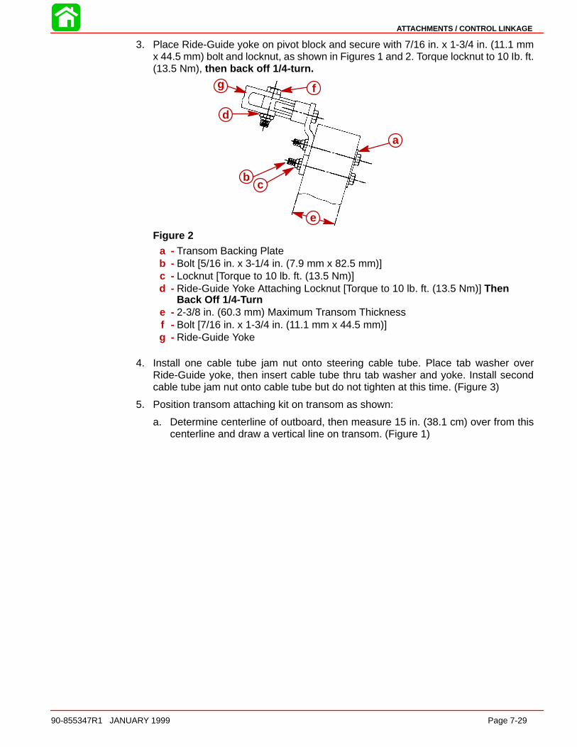
ATTACHMENTS / CONTROL LINKAGE
90-855347R1 JANUARY 1999 Page 7-29
3. Place Ride-Guide yoke on pivot block and secure with 7/16 in. x 1-3/4 in. (11.1 mmx 44.5 mm) bolt and locknut, as shown in Figures 1 and 2. Torque locknut to 10 Ib. ft.(13.5 Nm), then back off 1/4-turn.
a
bc
d
e
fg
Figure 2a - Transom Backing Plateb - Bolt [5/16 in. x 3-1/4 in. (7.9 mm x 82.5 mm)]c - Locknut [Torque to 10 lb. ft. (13.5 Nm)]d - Ride-Guide Yoke Attaching Locknut [Torque to 10 lb. ft. (13.5 Nm)] Then
Back Off 1/4-Turne - 2-3/8 in. (60.3 mm) Maximum Transom Thicknessf - Bolt [7/16 in. x 1-3/4 in. (11.1 mm x 44.5 mm)]g - Ride-Guide Yoke
4. Install one cable tube jam nut onto steering cable tube. Place tab washer overRide-Guide yoke, then insert cable tube thru tab washer and yoke. Install secondcable tube jam nut onto cable tube but do not tighten at this time. (Figure 3)
5. Position transom attaching kit on transom as shown:
a. Determine centerline of outboard, then measure 15 in. (38.1 cm) over from thiscenterline and draw a vertical line on transom. (Figure 1)

ATTACHMENTS / CONTROL LINKAGE
Page 7-30 90-855347R1 JANUARY 1999
b. Position attaching kit on transom so that transom bracket is centered on the 15in. (38.1 mm) (Figure 1) at a height where the center of Ride-Guide yoke is evenwith, or not more than 1/2 in. (12.7 mm) above top edge of transom. (Figure 3)
a
b
c
d
ef
fe
g
h
i
j
k
Figure 3a - Ride-Guide Yokeb - 0 in. to 1/2 in. (0 mm to 12.8 mm) (Center of Ride-Guide Yoke to Top of Tran-
som)c - Top of Transomd - Transom Brackete - Cable Tube Jam Nuts [Torque to 35 lb. ft. (47.5 Nm)]f - Tab Washerg - After Jam Nuts Are Torqued to Specification, Bend Locking Tabs against Nutsh - Cable Guide Tubei - Ride-Guide Cable Attaching Nut [Torque to 35 lb. ft. (47.5 Nm)]j - “Clevis Kit”k - Clevis Attaching Locknut [Torque to 20 lb. ft. (27 Nm)]
NOTE: When drilling thru transom, be sure that holes are drilled perpendicular to tran-som.
6. With attaching kit positioned as outlined preceding, use 3 holes in transom bracketas a guide and drill three 11/32 in. (8.7 mm) holes thru transom.
7. Use a marine-type sealer on three 5/16 in. x 3-1/4in. (7.9mm x 82.6mm) bolts. Secureattaching kit to transom, using transom backing plate, 3 bolts (with sealer) and 3 lock-nuts, installed as shown in Figure 2. Torque lock nuts to 10 Ib. ft. (13.5 Nm).
STEERING CABLE INSTALLATION
1. Lubricate steering cable end with Quicksilver 2-4-C w/Teflon (92-825407A12).
2. Install steering cable thru steering cable tube and secure to cable tube with cable at-taching nut. (Figure 3) Do not tighten cable attaching nut at this time.
3. Attach Ride-Guide cable to outboard steering arm, using the proper “Clevis Kit.” In-stallation instructions for clevis are with “Clevis Kit.”
4. Adjust 2 large jam nuts on cable tube of attaching kit, so that steering wheel is in nor-mal straight-driving position with outboard in straight-running position. Torque eachjam nut to 35 Ib. ft. (47.5 Nm), then bend a side of tab washer against flat of each jamnut. (Figure 3)
5. Torque Ride-Guide cable attaching nut (which secures cable to guide tube) to 35 Ib.ft. (47.5 Nm). (Figure 3)
ATTACHMENTS / CONTROL LINKAGE
90-855347R1 JANUARY 1999 Page 7-31
WARNINGAfter installation is completed (and before operating outboard), check that boatwill turn right when steering wheel is turned right and that boat will turn left whensteering wheel is turned left. Check steering thru full range (left and right) at alltilt angles to assure interference-free movement.
Maintenance InstructionsLubrication and maintenance inspection is owner’s responsibility and must be performedat intervals specified, following:
Normal Service - Every 50 hrs. of operation or 60 days (whichever comes first)
*Severe Service - Every 25 hrs. of operation or 30 days (whichever comes first)
*Operation in a salt water area is considered “Severe Service. ”
CAUTIONCore of steering cable must be fully retracted into cable housing when lubricatingcable. If cable is lubricated while extended, hydraulic lock of cable could occur.
1. Lubricate outboard end of Ride-Guide steering cable (thru grease fitting - if equipped- next to cable attaching nut) with Quicksilver 2-4-C w/Teflon.
NOTE: Ride-Guide steering cable is lubricated at the factory and requires no additionallubrication at initial installation.
2. Lubricate all steering system pivot points (and exposed portion of steering cable core)with Quicksilver 2-4-C w/Teflon. Lubricate at intervals specified preceding.
3. Carefully check steering system components for wear (at intervals specified, preced-ing). Replace worn parts.
4. Check steering system fasteners (at intervals specified, preceding) to be sure thatthey are torqued to correct specifications. (Figures 1, 2 and 3)

ATTACHMENTS / CONTROL LINKAGE
Page 7-32 90-855347R1 JANUARY 1999
Clevis Attaching Kit Installation (A-70599A5)NOTE: This kit is used to attach Ride-Guide cable to outboard steering arm ONLY when“Transom Mounted Ride-Guide Attaching Kit” is being used. If Ride-Guide cable isinstalled thru outboard tilt tube, then “Steering Link Rod” must be used.
Installation Instructions1. Install clevis to steering cable as shown.
2. Lubricate 3/8 in. x 1-3/8 in. (9.5 mm x 34.9 mm) bolt (area without threads) with 2-4-Cw/Teflon, then secure clevis to steering cable with this bolt and a locknut. Torque lock-nut (item “d”) to 10 Ib. ft. (13.5 Nm).
ab
c d
e
f
ghi
j
a - Clevisb - Steering Cablec - Bolt [3/8 in. x 1-3/8 in. (9.5 mm x 34.9 mm)]d - Clevis to Steering Cable Locknut [Torque to 10 lb. ft. (13.5 Nm)]e - Bolt [3/8 in. x 1-1/4 in. (9.5 mm x 31.8 mm)] [Torque to 20 lb. ft. (27 Nm)]f - Thin Washer [1/16 in. (1.6 mm) Thick]g - Spacerh - Thick Washer [1/8 in. (3.2 mm) Thick]i - Engine Steering Armj - Clevis to Engine Locknut [Torque to 20 lb. ft. (27 Nm)]
3. Lubricate spacer (supplied with this kit) with 2-4-C w/Teflon.
4. Attach clevis to top of outboard steering arm with a 3/8 in. x 1-1/4 in. (9.5 mm x 31.8mm) bolt, thin washer, spacer, thick washer (thick washer must be installed betweenclevis and steering arm) and locknut, as shown. Torque bolt (item “e”) to 20 Ib. ft. (27Nm), then torque locknut (item “j”) to 20 Ib. ft. (27 Nm).
Maintenance InstructionsLubrication and maintenance inspection is owner’s responsibility and must be performedat intervals specified, following:
Normal Service - Every 50 hrs. of operation or 60 days (whichever comes first)
*Severe Service - Every 25 hrs. of operation or 30 days (whichever comes first)
*Operation in a salt water area is considered “Severe Service.”
1. Carefully check steering system components (at intervals specified, preceding) forwear. Replace worn parts.
2. Check steering system fasteners (at intervals specified, preceding) to be sure thatthey are torqued to correct specifications.
3. Lubricate clevis pivot points with a drop of light oil. Lubricate at intervals specified, pre-ceding.

8
COLOR DIAGRAMS
Page 8-190-859494R1 JUNE 2000
COLOR DIAGRAMS
Table of Contents
2.5 Litre OptiMax 2000 Model Year Analog Wiring Diagram Page 8-3. . . . . . . . . . . . . . . . . . . . . . . . 2.5 Litre OptiMax 2000 Model Year Digital Wiring Diagram Page 8-5. . . . . . . . . . . . . . . . . . . . . . . . 2.5 Litre OptiMax 2001 Model Year Wiring Diagram Page 8-7. . . . . . . . . . . . . . . . . . . . . . . . Typical SmartCraft (Non CAN) Installation 2000 Model Year Page 8-9. . . . . . . . . . . . . . . . . . . . . . .
Typical SmartCraft Control Area Network (CAN) Installation 2001 Model Year Page 8-11. . . . . . . . . . . . . 2.5 Litre OptiMax 2000 & 2001 Model Year Fuel & Air Flow Diagram Page 8-13. . . . . . . . . . . . . . . . 2.5 Litre OptiMax 2000 & 2001 Model Year Water Flow Diagram Page 8-15. . . . . . . . . . . . . . . . . . . .

COLOR DIAGRAMS
Page 8-2 90-857138R1 MAY 2000

COLOR DIAGRAMS
Page 8-390-859494R1 JUNE 2000
2.5 LITRE OPTIMAX2000 MODEL YEAR
ANALOG WIRING DIAGRAM
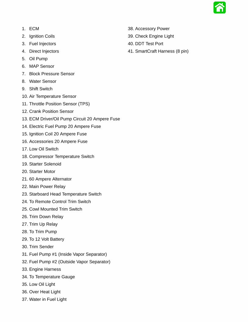
1. ECM
2. Ignition Coils
3. Fuel Injectors
4. Direct Injectors
5. Oil Pump
6. MAP Sensor
7. Block Pressure Sensor
8. Water Sensor
9. Shift Switch
10. Air Temperature Sensor
11. Throttle Position Sensor (TPS)
12. Crank Position Sensor
13. ECM Driver/Oil Pump Circuit 20 Ampere Fuse
14. Electric Fuel Pump 20 Ampere Fuse
15. Ignition Coil 20 Ampere Fuse
16. Accessories 20 Ampere Fuse
17. Low Oil Switch
18. Compressor Temperature Switch
19. Starter Solenoid
20. Starter Motor
21. 60 Ampere Alternator
22. Main Power Relay
23. Starboard Head Temperature Switch
24. To Remote Control Trim Switch
25. Cowl Mounted Trim Switch
26. Trim Down Relay
27. Trim Up Relay
28. To Trim Pump
29. To 12 Volt Battery
30. Trim Sender
31. Fuel Pump #1 (Inside Vapor Separator)
32. Fuel Pump #2 (Outside Vapor Separator)
33. Engine Harness
34. To Temperature Gauge
35. Low Oil Light
36. Over Heat Light
37. Water in Fuel Light
38. Accessory Power
39. Check Engine Light
40. DDT Test Port
41. SmartCraft Harness (8 pin)
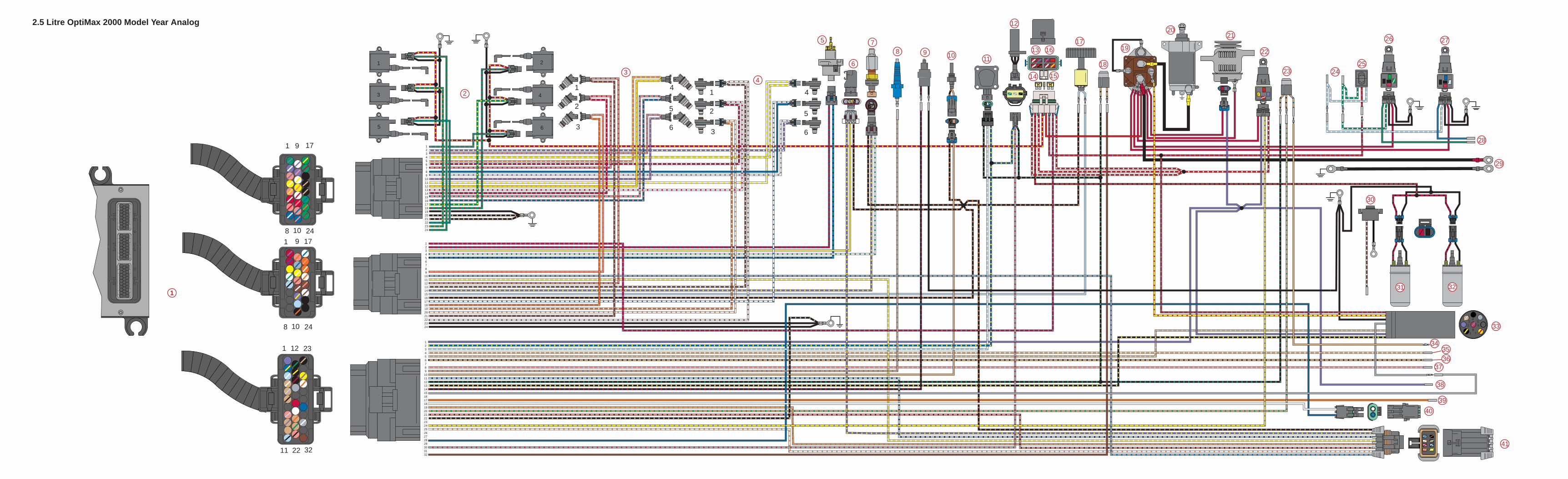
123456789
101112131415161718192021222324
123456789
101112131415161718192021222324
123456789
1011121314151617181920212223242526272829303132
6
4
2
3
1
5
1
2
3
4
5
6
1
2
3
4
5
6
1 9 17
8 10 24
1
11
12
22
23
32
1 9 17
8 10 241
23
456
78
2.5 Litre OptiMax 2000 Model Year Analog
1
2
34
5
6
78 9 10 11
12
13 16
14 15
17
18
19
2021
22
23 2425
26 27
28
29
31 32
33
343536
37
38
39
40
41
30

COLOR DIAGRAMS
Page 8-590-859494R1 JUNE 2000
2.5 LITRE OPTIMAX2000 MODEL YEAR
DIGITAL WIRING DIAGRAM
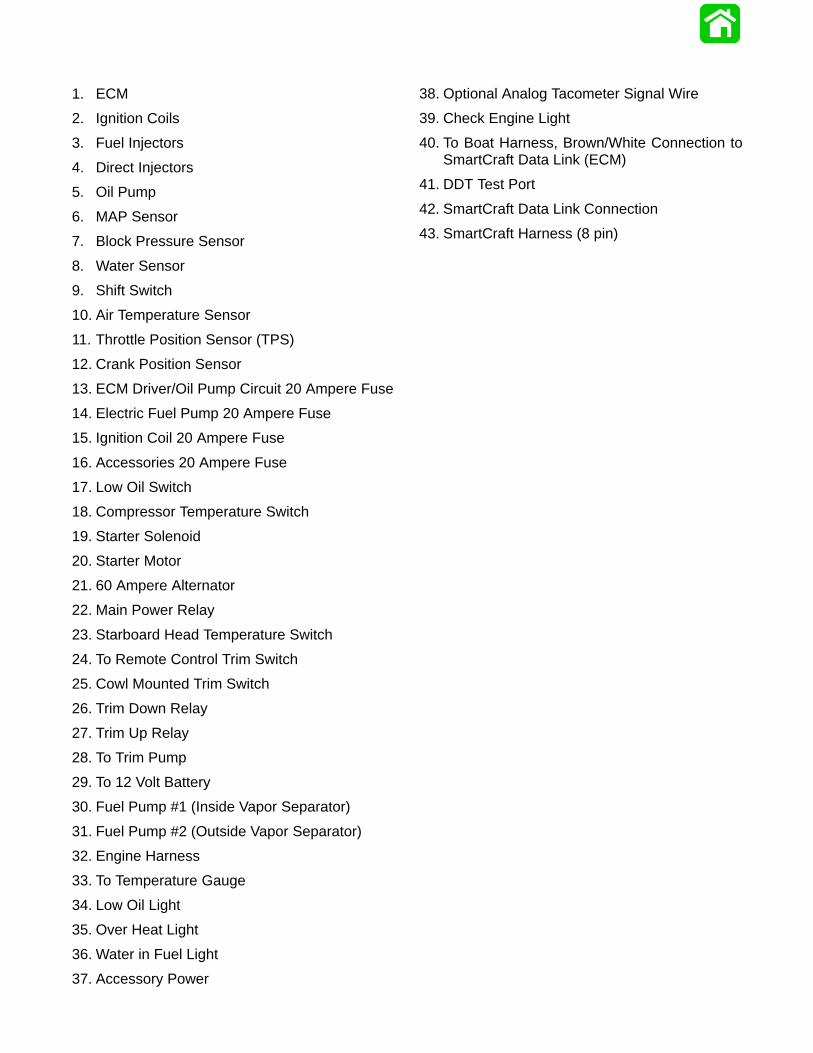
1. ECM
2. Ignition Coils
3. Fuel Injectors
4. Direct Injectors
5. Oil Pump
6. MAP Sensor
7. Block Pressure Sensor
8. Water Sensor
9. Shift Switch
10. Air Temperature Sensor
11. Throttle Position Sensor (TPS)
12. Crank Position Sensor
13. ECM Driver/Oil Pump Circuit 20 Ampere Fuse
14. Electric Fuel Pump 20 Ampere Fuse
15. Ignition Coil 20 Ampere Fuse
16. Accessories 20 Ampere Fuse
17. Low Oil Switch
18. Compressor Temperature Switch
19. Starter Solenoid
20. Starter Motor
21. 60 Ampere Alternator
22. Main Power Relay
23. Starboard Head Temperature Switch
24. To Remote Control Trim Switch
25. Cowl Mounted Trim Switch
26. Trim Down Relay
27. Trim Up Relay
28. To Trim Pump
29. To 12 Volt Battery
30. Fuel Pump #1 (Inside Vapor Separator)
31. Fuel Pump #2 (Outside Vapor Separator)
32. Engine Harness
33. To Temperature Gauge
34. Low Oil Light
35. Over Heat Light
36. Water in Fuel Light
37. Accessory Power
38. Optional Analog Tacometer Signal Wire
39. Check Engine Light
40. To Boat Harness, Brown/White Connection toSmartCraft Data Link (ECM)
41. DDT Test Port
42. SmartCraft Data Link Connection
43. SmartCraft Harness (8 pin)
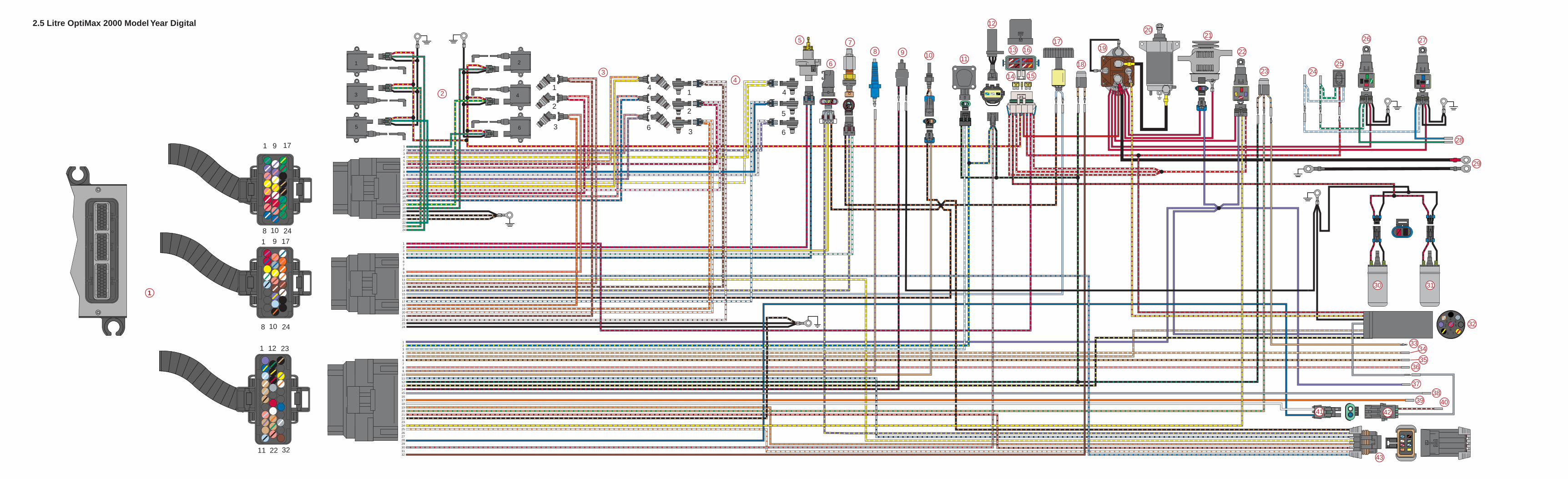
123456789
101112131415161718192021222324
123456789
101112131415161718192021222324
123456789
1011121314151617181920212223242526272829303132
6
4
2
3
1
5
1
2
3
4
5
6
1
2
3
4
5
6
1 9 17
8 10 24
1
11
12
22
23
32
1 9 17
8 10 241
23
456
78
2.5 Litre OptiMax 2000 Model Year Digital
1
2
34
5
6
78 9 10 11
12
13 16
14 15
17
18
19
2021
22
23 2425
26 27
28
29
30 31
32
3334
3536
3738
39 4041 42
43

COLOR DIAGRAMS
Page 8-790-859494R1 JUNE 2000
2.5 LITRE OPTIMAX2001 MODEL YEARWIRING DIAGRAM
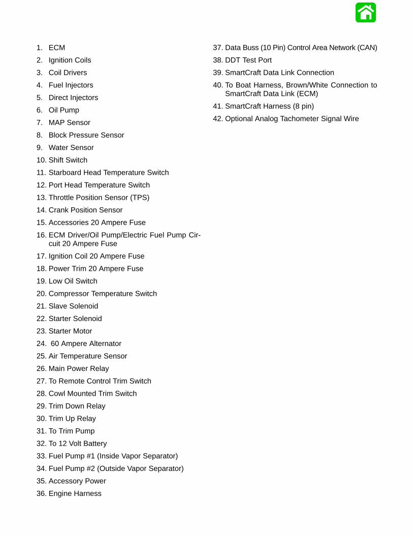
1. ECM
2. Ignition Coils
3. Coil Drivers
4. Fuel Injectors
5. Direct Injectors
6. Oil Pump
7. MAP Sensor
8. Block Pressure Sensor
9. Water Sensor
10. Shift Switch
11. Starboard Head Temperature Switch
12. Port Head Temperature Switch
13. Throttle Position Sensor (TPS)
14. Crank Position Sensor
15. Accessories 20 Ampere Fuse
16. ECM Driver/Oil Pump/Electric Fuel Pump Cir-cuit 20 Ampere Fuse
17. Ignition Coil 20 Ampere Fuse
18. Power Trim 20 Ampere Fuse
19. Low Oil Switch
20. Compressor Temperature Switch
21. Slave Solenoid
22. Starter Solenoid
23. Starter Motor
24. 60 Ampere Alternator
25. Air Temperature Sensor
26. Main Power Relay
27. To Remote Control Trim Switch
28. Cowl Mounted Trim Switch
29. Trim Down Relay
30. Trim Up Relay
31. To Trim Pump
32. To 12 Volt Battery
33. Fuel Pump #1 (Inside Vapor Separator)
34. Fuel Pump #2 (Outside Vapor Separator)
35. Accessory Power
36. Engine Harness
37. Data Buss (10 Pin) Control Area Network (CAN)
38. DDT Test Port
39. SmartCraft Data Link Connection
40. To Boat Harness, Brown/White Connection toSmartCraft Data Link (ECM)
41. SmartCraft Harness (8 pin)
42. Optional Analog Tachometer Signal Wire
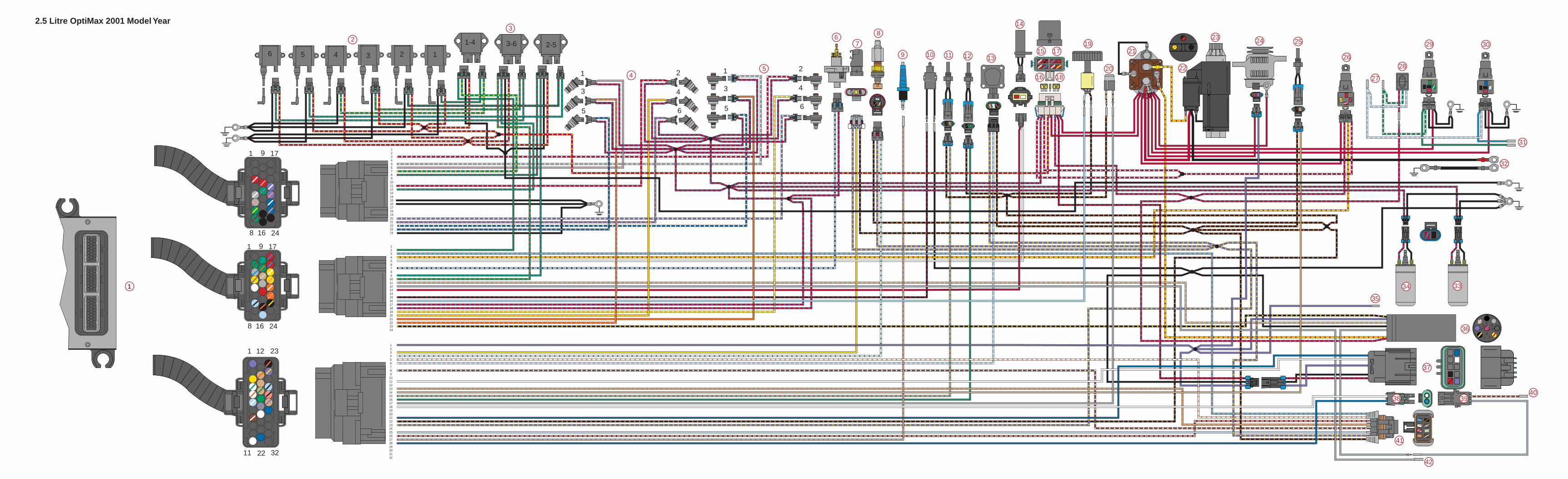
123456789
101112131415161718192021222324
123456789
101112131415161718192021222324
123456789
1011121314151617181920212223242526272829303132
1
3
5
2
4
6
1
3
5
2
4
6
1-4 3-6 2-5135 246
1
11
12
22
23
32
1
8
9
16
17
24
1
8
9
16
17
241
23
456
78
2.5 Litre OptiMax 2001 Model Year
2
3
45
67
8
9 10 11 12 13
14
15 17
16 18
19
20
21
22
23 24 25
26
27
28
29 30
31
32
3334
35
36
37
38 3940
1
41
42

COLOR DIAGRAMS
Page 8-990-859494R1 JUNE 2000
TYPICAL SMARTCRAFT (NON CAN)
INSTALLATION2000 MODEL YEAR

1. 8-Pin Digital Sensor Harness Extension Connection to Engine Wiring Harness
2. Digital Speedometer Sensor
3. Digital Trim Sender
4. 6-Pin Digital Sensor Harness
5. Connection for Analog Temperature Sender
6. Connections to Trim Relays
7. Connection to SmartCraft Data Link (ECM) Two Wire Harness
8. Remote Control Harness Connects to Engine Harness
9. Digital Connections for Fuel Sender
10. Digital Connections to Oil Sender
11. 4-Pin Digital Sensor Harness Connection to Paddle Wheel
12. Paddle Wheel/Lake/Sea Water Temperature Sender
13. Analog Temperature Gauge Connection
14. Warning Horn
15. Tachometer Harness
16. SmartCraft Tachometer Harness
17. Ignition Key Switch
18. Connections for Neutral Start Switch
19. Connections for Power Trim Switch
20. Connections for Lanyard Stop Switch
21. Mechanical Panel Control (MPC) 4000
22. Connection to 12 Volt Power Supply of Engine being Monitored
23. Connection for Optional Visual Warning Light
24. SmartCraft Tachometer
25. Connection Between SmartCraft Tachometer Harness and SmartCraft Tachometer
26. Connection Between SmartCraft Tachometer Harness and SmartCraft Speedometer Harness
27. Connection for Optional GPS
28. Connection Between SmartCraft Speedometer Harness and SmartCraft Speedometer
29. SmartCraft Speedometer
30. Connection for Ambient Air Temperature Sensor
31. Ambient Air Temperature Sensor
32. Connection for Second SmartCraft Tachometer (Dual Outboard Application)
33. SmartCraft Tachometer Harness (Dual Outboard Application)
34. SmartCraft Tachometer (Dual Outboard Application)
35. Connection for Optional Visual Warning Light (Dual Outboard Application)
36. Connection to 12 Volt Power Supply of Second Engine being Monitored (Dual Outboard Application)
37. Connection to Second Remote Control Tachometer Harness (Dual Outboard Application)
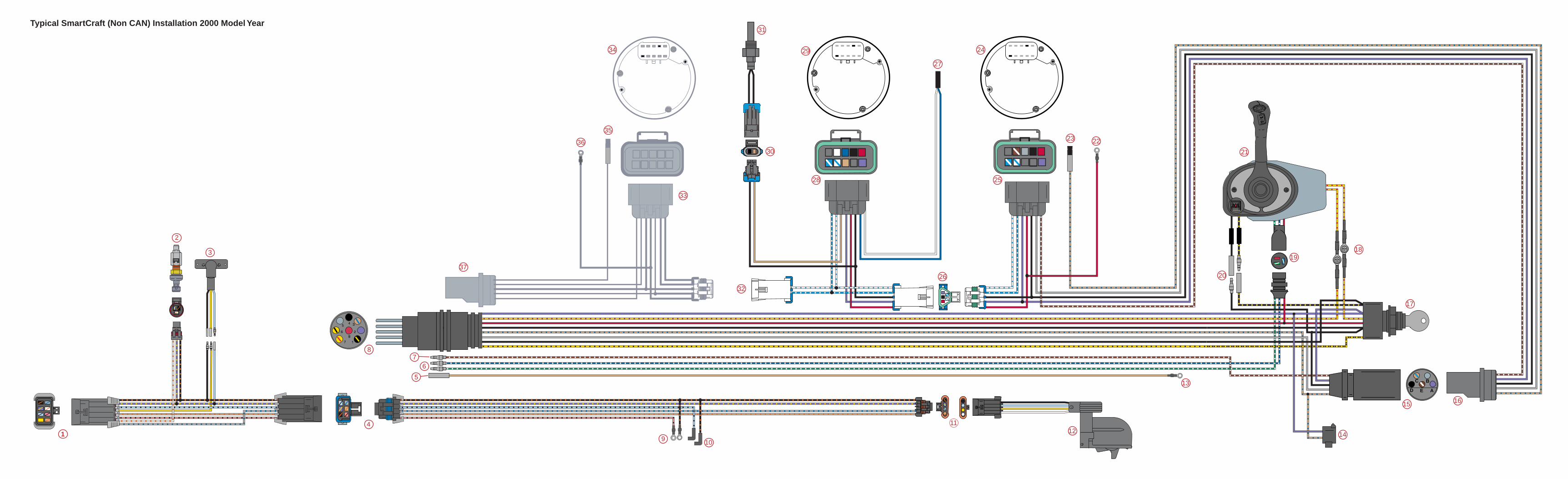
C
D E A
B
Typical SmartCraft (Non CAN) Installation 2000 Model Year
2
3
4
5
67
8
9 10
1112
13
14
15 16
17
1819
20
21
2223
24
25
26
27
28
29
30
31
32
33
34
35
36
37
1

COLOR DIAGRAMS
Page 8-1190-859494R1 JUNE 2000
TYPICAL SMARTCRAFT (CAN)
INSTALLATION2001 MODEL YEAR

1. 8-Pin Digital Sensor Harness Extension, Connect to 8-Pin SmartCraft Harness on Engine
2. Digital Speedometer Sensor
3. Digital Trim Sender
4. 6-Pin Digital Sensor Harness
5. Connection for Analog Temperature Sender
6. Connections to Trim Relays
7. Connection for Analog Trim Sender
8. Remote Control Harness Connects to Engine Harness
9. 10-Pin Control Area Network (CAN) Harness, Connect to Data Buss 10-Pin CAN Harness on Engine
10. Resistors within CAN Harness (120Ω 1/4W 5%)
11. Connections for Auxiliary Warning Horn for Depth Sensor
12. 10-Pin Control Area Network (CAN) Connection to System Monitor
13. System Monitor
14. System Link Series Connections
15. 3-1/4 in. System Link Gauges (Tachometer and Speedometer)
16. 2-1/4 in. Dia. System Link Gauges (Fuel, Temperature, Trim, etc.)
17. Series Connection for Additional System Link Gauges
18. 4000 Series Mechanical Panel Control (MPC 4000)
19. Connections for Lanyard Stop Switch
20. Connections for Power Trim Switch
21. Connections for Neutral Start Safety Switch
22. Ignition Key Switch
23. Analog Tachometer Harness (Not Used on CAN Installation)
24. Warning Horn
25. Analog Temperature Gauge Connection
26. Paddle Wheel/Lake/Sea Water Temperature Sender
27. 4-Pin Digital Sensor Harness Connection to Paddle Wheel
28. Digital Connections to Oil Sender
29. Digital Connections for Fuel Sender

Typical SmartCraft (CAN) Installation 2001 Model Year
C
D E A
B
1
2
3
4
5
67
8
9
10
11
12
13
14
14 14 14
17
1515
16 16
18
19
20
21
22
23
24
25
26
27
2829
10

COLOR DIAGRAMS
Page 8-1390-859494R1 JUNE 2000
2.5 LITRE OPTIMAX2000 & 2001 MODEL YEAR
FUEL & AIR FLOW DIAGRAM

1. Fuel inlet from primer bulb
2. Engine Pulse Fuel Pump
3. Fuel line to Water Separating Fuel Filter – 2-8 psi (14-55 kPa)
4. Water Separating Fuel Filter in Vapor Separator Tank (VST) Assembly
5. Fuel outlet from VST
6. Fuel Inlet to Low Pressure Electric Fuel Pump
7. Fuel outlet from Low Pressure Electric Fuel Pump – 7-9 psi (48-62 kPa)
8. Fuel inlet to High Pressure Electric Fuel Pump.
9. Relief Passage – Unused fuel returning to VST
10. Air Vent to VST
11. Fuel outlet from High Pressure Electric Fuel Pump – 90 psi (620 kPa)
12. High pressure fuel Inlet to Air/Fuel Rails – 90 psi (620 kPa)
13. Fuel Injector is opened by the ECM, 90 psi (620 kPa) fuel is discharged into a machined cavity insidethe air chamber of the air/fuel rail. This mixes the fuel with the air charge.
14. Air Inlet to Air Compressor
15. Air Compressor
16. High Pressure Air Outlet – 80 psi (551 kPa)
17. High Pressure Air Inlet to Air/Fuel Rails – 80 psi (551 kPa)
18. Direct Injector discharges the air/fuel mixture into the combustion chamber
19. Schrader Valve for Testing Air Pressure
20. Schrader Valve for Testing Fuel Pressure
21. Air Pressure Regulator will limit the amount of pressure developed inside the air passages to approxi-mately 10 psi (69 kPa) below the pressure of the fuel inside the fuel passages (i.e. 80 psi [551 kPa] airvs 90 psi [620 kPa] fuel)
22. Bleed Off from Air Pressure Regulator, Routed to the Exhaust Adaptor and Exits thru the Propeller
23. Fuel Pressure Regulator not only regulates fuel pressure but also regulates it at approximately 10 p.s.i.(69 kPa) higher than whatever the air rail pressure is. The fuel regulator diaphragm is held closed witha spring that requires 10 p.s.i. (69 kPa) to force the diaphragm off the diaphragm seat. The back sideof the diaphragm is exposed to air rail pressure. As the air rail pressure increases, the fuel pressureneeded to open the regulator will equally increase.
24. Bleed off from Fuel Pressure Regulator, Routed Back to VST
25. Tracker Valve has a rubber diaphragm which expands and retracts to equalize the pulses developedby the pumps (both air and fuel).
26. Check Valve – 40 psi (276 kPa)
27. Fuel return inlet from Fuel Regulator
28. Water Inlet to cool port air/fuel rail and air compressor
29. Cooling water from Compressor routed to Tell-Tale
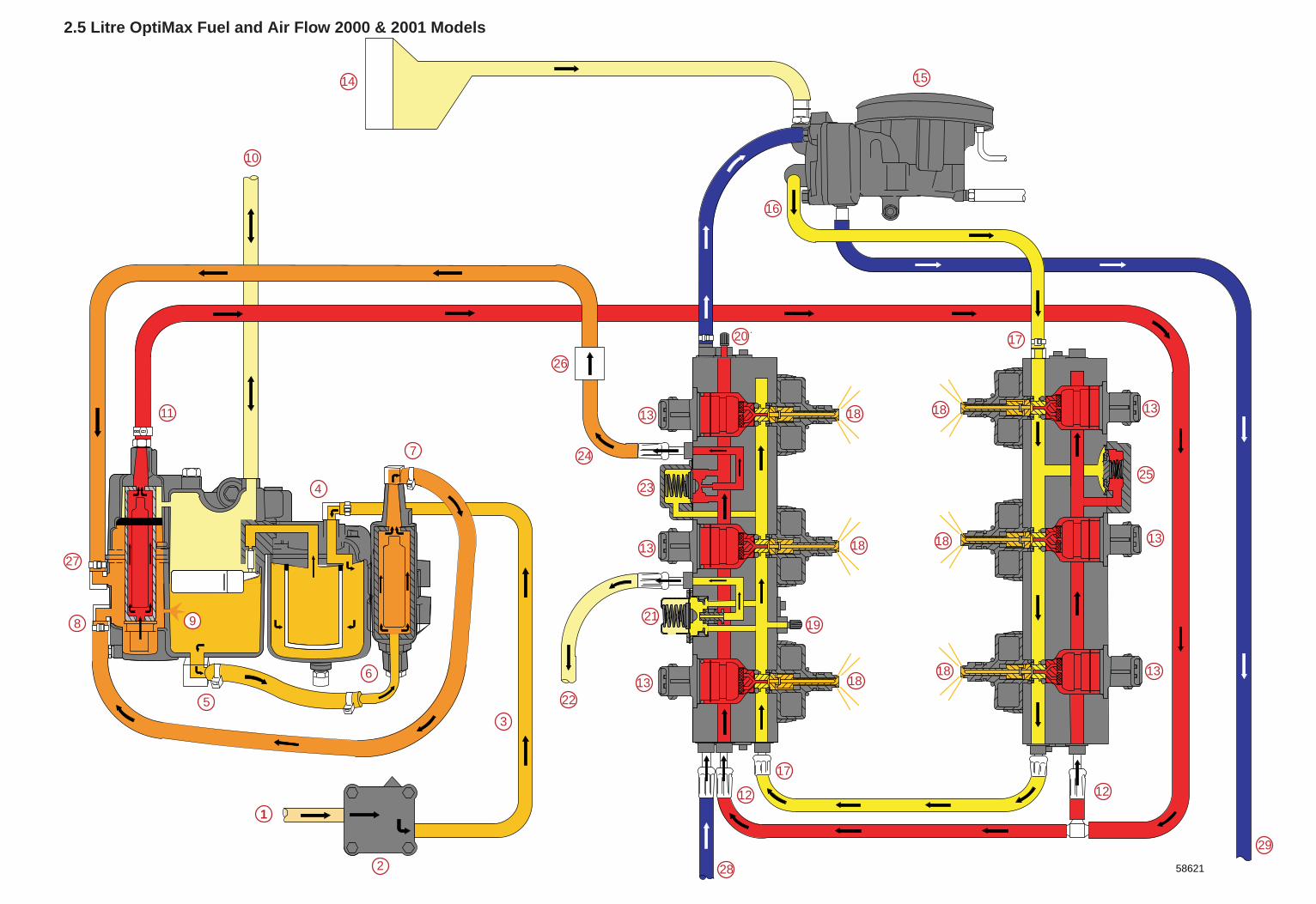
58621
2.5 Litre OptiMax Fuel and Air Flow 2000 & 2001 Models
1
2
3
4
5
6
7
8 9
10
11
12
15
16
17
18
19
20
21
22
23
24
25
26
27
12
13
13
13
13
13
13
14
17
18
18
18
1818
28
29

COLOR DIAGRAMS
Page 8-1590-859494R1 JUNE 2000
2.5 LITRE OPTIMAX2000 & 2001 MODEL YEARWATER FLOW DIAGRAM

1. Water Inlet
2. Water Pump
3. Wall of Water – If water level height is insufficient, water pump may draw in air resulting in an overheatedengine
4. Water Tube
5. Cylinder Head Cover – Removed from head for illustration, normally part of head casting
6. Thermostats (2) 143° F (61.7° C) – If stuck closed, engine will overheat at idle
7. Poppet Valve – Controls water flow at high RPM. If poppet valve is stuck open at low RPM, the enginewill not reach proper operating temperature (run cold) and will run rough at idle
8. Exhaust Divider Plate – Separated for illustration
9. Strainer Screen for air compressor and fuel rail water supply – If restricted, compressor will overheatand tell-tale will be weak
10. Port Fuel Rail – Fuel Cooler is built into Port Fuel Rail
11. Air Compressor
12. Water Outlet from Air Compressor – Connects to tell-tale outlet on bottom cowl
13. Check Valve for powerhead flush.
14. Block Water Pressure Sensor
15. Water passing through thermostats dump into the adaptor plate, then discharges down the exhaust
16. Primary Water Discharge into Driveshaft Housing
17. Water Dump Holes Exhaust Cooling (2 each) 1/8 in. (3.175 mm) – If holes are plugged, tuner pipe willmelt and bearing carrier prop shaft seals will be damaged
18. Excess water from wall of water around exhaust bucket exits around anodes
19. Water Exits with Exhaust Discharge
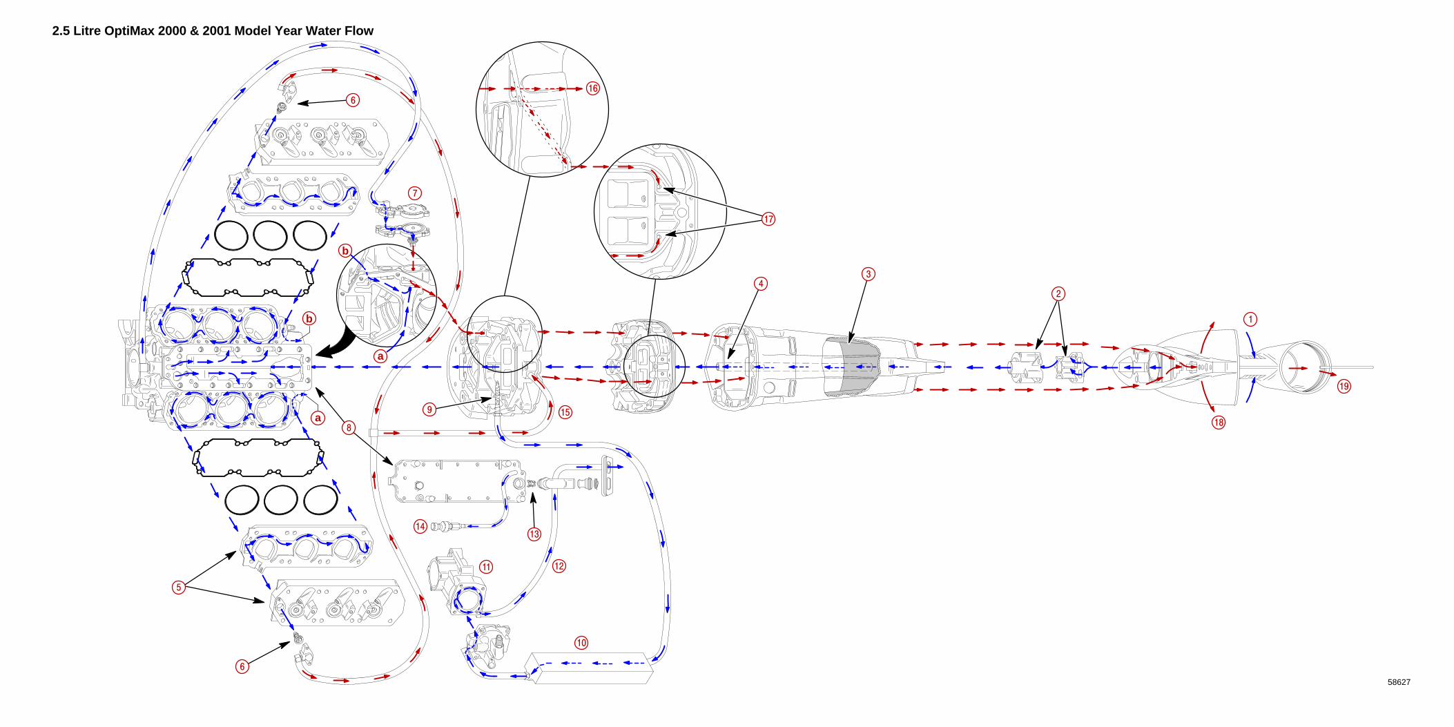
2.5 Litre OptiMax 2000 & 2001 Model Year Water Flow
58627
1
15
14
a
a
b
b
2
3
4
5
6
6
7
8
9
10
11 12
16
18
13
17
19

1A
SPECIFICATIONS
90-859494R1 JUNE 2000 Page 1A-1
IMPORTANT INFORMATIONSection 1A - Specifications
Table of Contents
Master Specifications 1A-1. . . . . . . . . . . . . . . . . . . . . . . . . Propeller Information Charts 1A-7. . . . . . . . . . . . . . . . . . .
Master Specifications
Model 115/135/150/175 DFIHORSEPOWER
(KW)Model 115Model 135Model 150Model 175Full Throttle RPM (115/135)Full Throttle RPM (150/175)Idle RPM (In Gear) (115/135/150/175)RPM Limiter
All Models
115 (85.8 kw)135 (100.7 kw)150 (111.8 kw)175 (130.5 kw)
5000 - 55005250 - 5750
550 ± 25
Refer to System Information in the Digi-tal Diagnostic Terminal (DDT) for latest
information
OUTBOARDWEIGHT
Model 115/135/150/175– 20 in. (50.8cm) Shaft– 25 in. (63.5cm) Shaft
453 (205.5 kg)462 (209.6 kg)
CYLINDERBLOCK
TypeDisplacement Thermostat
V-6 Cylinder, Two Cycle, Direct Injected153 cu. in. (2508 cc) 60° Vee
142° F (61° C)
STROKE Length (All Models) 2.65 in. (67.3 mm)
CYLINDERBORE
Diameter (Std)Diameter 0.015 in. OversizeTaper/Out of Round/Wear MaximumBore Type
3.501 in. (88.925 mm)3.516 in. (89.306 mm)0.003 in. (0.076 mm)
Cast Iron
CRANKSHAFT Maximum Runout 0.006 in. (0.152 mm)
PISTON Piston TypeDiameter Standard
Diameter 0.015 in. Oversize
Aluminum3.4925 in. ± .0005 in. (88.7095 mm ±
0.0127 mm)3.5075 in. ± 0.0005 in.
(89.0905 mm ± 0.0127 mm)
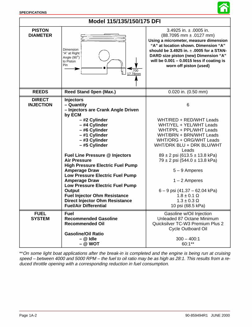
SPECIFICATIONS
Page 1A-2 90-859494R1 JUNE 2000
Model 115/135/150/175 DFI
PISTONDIAMETER
Dimension“A” at RightAngle (90°)to PistonPin
.70017.78mm
3.4925 in. ± .0005 in.(88.7095 mm ± .0127 mm)
Using a micrometer, measure dimension“A” at location shown. Dimension “A”
should be 3.4925 in. ± .0005 for a STAN-DARD size piston (new) Dimension “A”will be 0.001 – 0.0015 less if coating is
worn off piston (used)
REEDS Reed Stand 0pen (Max.) 0.020 in. (0.50 mm)
DIRECTINJECTION
Injectors– Quantity– Injectors are Crank Angle Driven by ECM
– #2 Cylinder– #4 Cylinder– #6 Cylinder– #1 Cylinder– #3 Cylinder– #5 Cylinder
Fuel Line Pressure @ InjectorsAir PressureHigh Pressure Electric Fuel PumpAmperage DrawLow Pressure Electric Fuel PumpAmperage DrawLow Pressure Electric Fuel PumpOutputFuel Injector Ohm ResistanceDirect Injector Ohm ResistanceFuel/Air Differential
6
WHT/RED + RED/WHT LeadsWHT/YEL + YEL/WHT LeadsWHT/PPL + PPL/WHT LeadsWHT/BRN + BRN/WHT LeadsWHT/ORG + ORG/WHT Leads
WHT/DRK BLU + DRK BLU/WHTLeads
89 ± 2 psi (613.5 ± 13.8 kPa)79 ± 2 psi (544.0 ± 13.8 kPa)
5 – 9 Amperes
1 – 2 Amperes
6 – 9 psi (41.37 – 62.04 kPa)1.8 ± 0.1 Ω1.3 ± 0.3 Ω
10 psi (68.5 kPa)
FUELSYSTEM
FuelRecommended GasolineRecommended Oil
Gasoline/Oil Ratio – @ Idle
– @ WOT
Gasoline w/Oil InjectionUnleaded 87 Octane Minimum
Quicksilver TC-W3 Premium Plus 2Cycle Outboard Oil
300 – 400:160:1**
**On some light boat applications after the break-in is completed and the engine is being run at cruisingspeed – between 4000 and 5000 RPM – the fuel to oil ratio may be as high as 28:1. This results from a re-duced throttle opening with a corresponding reduction in fuel consumption.

SPECIFICATIONS
90-859494R1 JUNE 2000 Page 1A-3
Model 115/135/150/175 DFIFUELPUMP
Fuel Pressure Crankcase Pump – @ Idle
– @ WOT
Normal – 2-3 psi (13.7 – 20.5 kPa) Minimum – 1 psi (6.8 kPa)
Maximum – 10 psi (68.5 kPa)Normal – 8-10 psi (41.0 – 54.8 kPa)
Minimum – 3 psi (20.5 kPa)
STARTINGSYSTEM
Electric Start – All ModelsModel Year 2000
Starter Draw (Under Load)Starter Draw (No Load)Minimum Brush Length
Model Year 2001Starter Draw (Under Load)Starter Draw (No Load)Minimum Brush Length
Battery Rating
165 Amperes30 Amperes
0.25 in. (65.4 mm)
170 Amperes60 Amperes
0.25 in. (65.4 mm)1000 (Minimum) Marine Cranking Amps
750 (Minimum) Cold Cranking Amps105 (Minimum) Ampere Hours
IGNITIONSYSTEM
TypeSpark Plug Type
Model Year 2000Spark Plug GapModel Year 2001Spark Plug Gap
Maximum TimingIdle TimingThrottle Position Sensor
@ Idle@ WOT
Crank Position SensorAir Gap
Digital Inductive
Champion QC12GMC0.040 in. (1.0 mm)NGK PZFR5F-110.040 in. (1.0 mm)
Not Adjustable; Controlled by ECMNot Adjustable; Controlled by ECM
4.0 – 4.7 VDC0.4 – 1.3 VDC
0.025 in. – 0.040 in. (0.635 mm – 1.01 mm)
CHARGINGSYSTEM
Alternator Output (Regulated)
Brush Length
Voltage OutputRegulator Current Draw
32 - 38 Amperes @ 2000 RPM @ Battery*52 - 60 Amperes @ 2000 RPM @
AlternatorStd Exposed Length: 0.413 in. (10.5 mm)Min. Exposed Length: 0.059 in. (1.5 mm)
13.5 to 15.1 Volts0.15 mA (Ign. Switch Off)30.0 mA (Ign. Switch On)
*Amperage listed is when battery is in a discharged state. If battery is fully charged, amperage readings willbe less.

SPECIFICATIONS
Page 1A-4 90-859494R1 JUNE 2000
Model 115/135/150/175 DFITIMING Full Throttle RPM Range
(115/135)(150/175
Idle RPM (In Forward Gear)Maximum Timing: @ Wide OPENIdle Timing
Throttle Position Sensor@ Idle@ W.O.T.
Firing Order
5000 - 55005250 - 5750
550 ± 25Not Adjustable Controlled by ECMNot Adjustable Controlled by ECM
3.20 - 4.90 VDC0.10 - 1.50 VDC
1-2-3-4-5-6
AIRCOMPRESSOR
Type
Compressor Output
Reciprocating Piston(1 to 1 ratio with engine RPM)
@ Idle – 80 psi@ W.O.T. – 110 psi
Cylinder Block Displacement 7.07 cu. in. (116 cc)
Cylinder BoreDiameter (Standard)Taper/Out-of-Round/Wear MaximumBore Type
2.5591 in. (65.0 mm)
0.001 in. (0.025 mm)Cast Iron
Stroke Length 1.374 in. (34.9 mm)
Piston Type Aluminum
Piston Diameter 2.5578 ± .0004 in.(64.97 ± 0.010 mm)
Dimension“A” atRightAngle(90°) toPiston Pin
0.500 in.
Piston Ring End GapTop Ring
Middle Ring
Bottom Ring
0.0059 – 0.0098 in. (0.15 – 0.25 mm)
0.0059 – 0.0098 in. (0.15 – 0.25 mm)
0.0039 – 0.014 in. (0.10 – 0.35 mm)
ReedsStand Open 0.010 in. (0.25 mm)
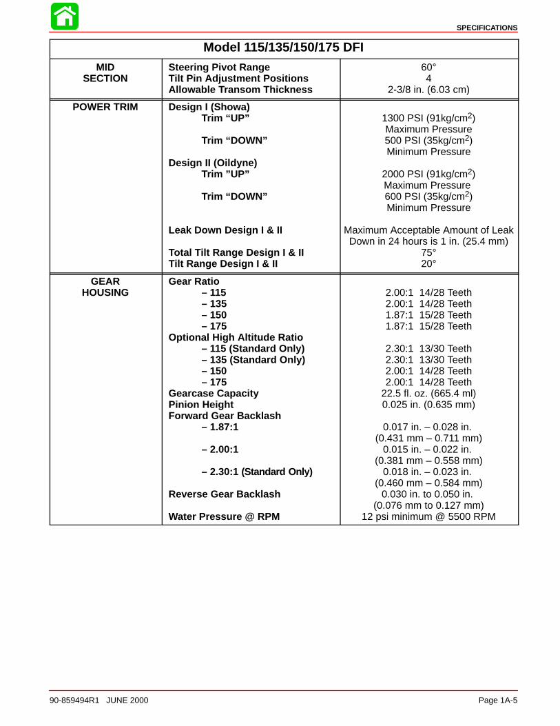
SPECIFICATIONS
90-859494R1 JUNE 2000 Page 1A-5
Model 115/135/150/175 DFI
MIDSECTION
Steering Pivot RangeTilt Pin Adjustment PositionsAllowable Transom Thickness
60°4
2-3/8 in. (6.03 cm)
POWER TRIM Design I (Showa)Trim “UP”
Trim “DOWN”
Design II (Oildyne)Trim ”UP”
Trim “DOWN”
Leak Down Design I & II
Total Tilt Range Design I & IITilt Range Design I & II
1300 PSI (91kg/cm2)Maximum Pressure500 PSI (35kg/cm2)Minimum Pressure
2000 PSI (91kg/cm2)Maximum Pressure 600 PSI (35kg/cm2)Minimum Pressure
Maximum Acceptable Amount of LeakDown in 24 hours is 1 in. (25.4 mm)
75°20°
GEARHOUSING
Gear Ratio – 115
– 135– 150– 175
Optional High Altitude Ratio– 115 (Standard Only)– 135 (Standard Only)– 150– 175
Gearcase CapacityPinion HeightForward Gear Backlash
– 1.87:1
– 2.00:1
– 2.30:1 (Standard Only)
Reverse Gear Backlash
Water Pressure @ RPM
2.00:1 14/28 Teeth2.00:1 14/28 Teeth1.87:1 15/28 Teeth1.87:1 15/28 Teeth
2.30:1 13/30 Teeth2.30:1 13/30 Teeth2.00:1 14/28 Teeth2.00:1 14/28 Teeth
22.5 fl. oz. (665.4 ml)0.025 in. (0.635 mm)
0.017 in. – 0.028 in. (0.431 mm – 0.711 mm)
0.015 in. – 0.022 in. (0.381 mm – 0.558 mm)
0.018 in. – 0.023 in. (0.460 mm – 0.584 mm)
0.030 in. to 0.050 in. (0.076 mm to 0.127 mm)
12 psi minimum @ 5500 RPM
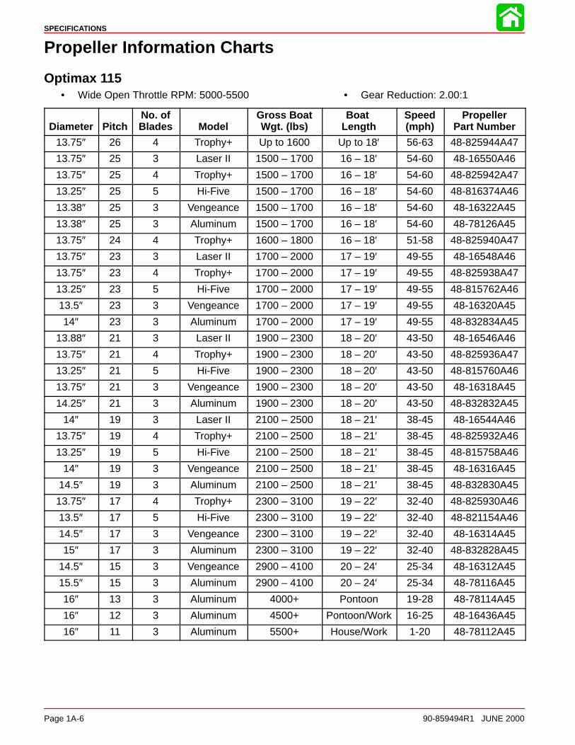
SPECIFICATIONS
Page 1A-6 90-859494R1 JUNE 2000
Propeller Information Charts
Optimax 115• Wide Open Throttle RPM: 5000-5500 • Gear Reduction: 2.00:1
Diameter PitchNo. ofBlades Model
Gross BoatWgt. (lbs)
Boat Length
Speed(mph)
PropellerPart Number
13.75″ 26 4 Trophy+ Up to 1600 Up to 18′ 56-63 48-825944A47
13.75″ 25 3 Laser II 1500 – 1700 16 – 18′ 54-60 48-16550A46
13.75″ 25 4 Trophy+ 1500 – 1700 16 – 18′ 54-60 48-825942A47
13.25″ 25 5 Hi-Five 1500 – 1700 16 – 18′ 54-60 48-816374A46
13.38″ 25 3 Vengeance 1500 – 1700 16 – 18′ 54-60 48-16322A45
13.38″ 25 3 Aluminum 1500 – 1700 16 – 18′ 54-60 48-78126A45
13.75″ 24 4 Trophy+ 1600 – 1800 16 – 18′ 51-58 48-825940A47
13.75″ 23 3 Laser II 1700 – 2000 17 – 19′ 49-55 48-16548A46
13.75″ 23 4 Trophy+ 1700 – 2000 17 – 19′ 49-55 48-825938A47
13.25″ 23 5 Hi-Five 1700 – 2000 17 – 19′ 49-55 48-815762A46
13.5″ 23 3 Vengeance 1700 – 2000 17 – 19′ 49-55 48-16320A45
14″ 23 3 Aluminum 1700 – 2000 17 – 19′ 49-55 48-832834A45
13.88″ 21 3 Laser II 1900 – 2300 18 – 20′ 43-50 48-16546A46
13.75″ 21 4 Trophy+ 1900 – 2300 18 – 20′ 43-50 48-825936A47
13.25″ 21 5 Hi-Five 1900 – 2300 18 – 20′ 43-50 48-815760A46
13.75″ 21 3 Vengeance 1900 – 2300 18 – 20′ 43-50 48-16318A45
14.25″ 21 3 Aluminum 1900 – 2300 18 – 20′ 43-50 48-832832A45
14″ 19 3 Laser II 2100 – 2500 18 – 21′ 38-45 48-16544A46
13.75″ 19 4 Trophy+ 2100 – 2500 18 – 21′ 38-45 48-825932A46
13.25″ 19 5 Hi-Five 2100 – 2500 18 – 21′ 38-45 48-815758A46
14″ 19 3 Vengeance 2100 – 2500 18 – 21′ 38-45 48-16316A45
14.5″ 19 3 Aluminum 2100 – 2500 18 – 21′ 38-45 48-832830A45
13.75″ 17 4 Trophy+ 2300 – 3100 19 – 22′ 32-40 48-825930A46
13.5″ 17 5 Hi-Five 2300 – 3100 19 – 22′ 32-40 48-821154A46
14.5″ 17 3 Vengeance 2300 – 3100 19 – 22′ 32-40 48-16314A45
15″ 17 3 Aluminum 2300 – 3100 19 – 22′ 32-40 48-832828A45
14.5″ 15 3 Vengeance 2900 – 4100 20 – 24′ 25-34 48-16312A45
15.5″ 15 3 Aluminum 2900 – 4100 20 – 24′ 25-34 48-78116A45
16″ 13 3 Aluminum 4000+ Pontoon 19-28 48-78114A45
16″ 12 3 Aluminum 4500+ Pontoon/Work 16-25 48-16436A45
16″ 11 3 Aluminum 5500+ House/Work 1-20 48-78112A45
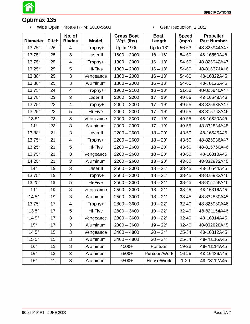
SPECIFICATIONS
90-859494R1 JUNE 2000 Page 1A-7
Optimax 135• Wide Open Throttle RPM: 5000-5500 • Gear Reduction: 2.00:1
Diameter PitchNo. ofBlades Model
Gross BoatWgt. (lbs)
Boat Length
Speed(mph)
PropellerPart Number
13.75″ 26 4 Trophy+ Up to 1900 Up to 18′ 56-63 48-825944A47
13.75″ 25 3 Laser II 1800 – 2000 16 – 18′ 54-60 48-16550A46
13.75″ 25 4 Trophy+ 1800 – 2000 16 – 18′ 54-60 48-825942A47
13.25″ 25 5 Hi-Five 1800 – 2000 16 – 18′ 54-60 48-816374A46
13.38″ 25 3 Vengeance 1800 – 2000 16 – 18′ 54-60 48-16322A45
13.38″ 25 3 Aluminum 1800 – 2000 16 – 18′ 54-60 48-78126A45
13.75″ 24 4 Trophy+ 1900 – 2100 16 – 18′ 51-58 48-825940A47
13.75″ 23 3 Laser II 2000 – 2300 17 – 19′ 49-55 48-16548A46
13.75″ 23 4 Trophy+ 2000 – 2300 17 – 19′ 49-55 48-825938A47
13.25″ 23 5 Hi-Five 2000 – 2300 17 – 19′ 49-55 48-815762A46
13.5″ 23 3 Vengeance 2000 – 2300 17 – 19′ 49-55 48-16320A45
14″ 23 3 Aluminum 2000 – 2300 17 – 19′ 49-55 48-832834A45
13.88″ 21 3 Laser II 2200 – 2600 18 – 20′ 43-50 48-16546A46
13.75″ 21 4 Trophy+ 2200 – 2600 18 – 20′ 43-50 48-825936A47
13.25″ 21 5 Hi-Five 2200 – 2600 18 – 20′ 43-50 48-815760A46
13.75″ 21 3 Vengeance 2200 – 2600 18 – 20′ 43-50 48-16318A45
14.25″ 21 3 Aluminum 2200 – 2600 18 – 20′ 43-50 48-832832A45
14″ 19 3 Laser II 2500 – 3000 18 – 21′ 38-45 48-16544A46
13.75″ 19 4 Trophy+ 2500 – 3000 18 – 21′ 38-45 48-825932A46
13.25″ 19 5 Hi-Five 2500 – 3000 18 – 21′ 38-45 48-815758A46
14″ 19 3 Vengeance 2500 – 3000 18 – 21′ 38-45 48-16316A45
14.5″ 19 3 Aluminum 2500 – 3000 18 – 21′ 38-45 48-832830A45
13.75″ 17 4 Trophy+ 2800 – 3600 19 – 22′ 32-40 48-825930A46
13.5″ 17 5 Hi-Five 2800 – 3600 19 – 22′ 32-40 48-821154A46
14.5″ 17 3 Vengeance 2800 – 3600 19 – 22′ 32-40 48-16314A45
15″ 17 3 Aluminum 2800 – 3600 19 – 22′ 32-40 48-832828A45
14.5″ 15 3 Vengeance 3400 – 4800 20 – 24′ 25-34 48-16312A45
15.5″ 15 3 Aluminum 3400 – 4800 20 – 24′ 25-34 48-78116A45
16″ 13 3 Aluminum 4500+ Pontoon 19-28 48-78114A45
16″ 12 3 Aluminum 5500+ Pontoon/Work 16-25 48-16436A45
16″ 11 3 Aluminum 6500+ House/Work 1-20 48-78112A45
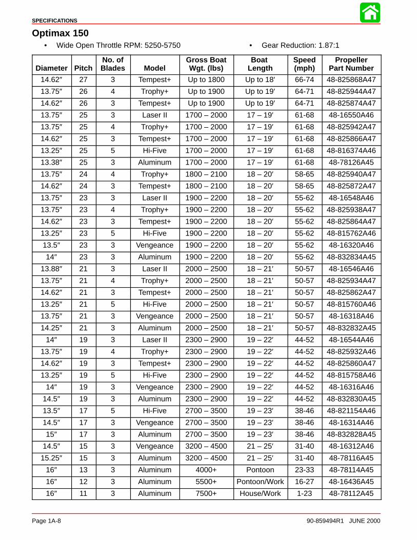
SPECIFICATIONS
Page 1A-8 90-859494R1 JUNE 2000
Optimax 150• Wide Open Throttle RPM: 5250-5750 • Gear Reduction: 1.87:1
Diameter PitchNo. ofBlades Model
Gross BoatWgt. (lbs)
Boat Length
Speed(mph)
PropellerPart Number
14.62″ 27 3 Tempest+ Up to 1800 Up to 18′ 66-74 48-825868A47
13.75″ 26 4 Trophy+ Up to 1900 Up to 19′ 64-71 48-825944A47
14.62″ 26 3 Tempest+ Up to 1900 Up to 19′ 64-71 48-825874A47
13.75″ 25 3 Laser II 1700 – 2000 17 – 19′ 61-68 48-16550A46
13.75″ 25 4 Trophy+ 1700 – 2000 17 – 19′ 61-68 48-825942A47
14.62″ 25 3 Tempest+ 1700 – 2000 17 – 19′ 61-68 48-825866A47
13.25″ 25 5 Hi-Five 1700 – 2000 17 – 19′ 61-68 48-816374A46
13.38″ 25 3 Aluminum 1700 – 2000 17 – 19′ 61-68 48-78126A45
13.75″ 24 4 Trophy+ 1800 – 2100 18 – 20′ 58-65 48-825940A47
14.62″ 24 3 Tempest+ 1800 – 2100 18 – 20′ 58-65 48-825872A47
13.75″ 23 3 Laser II 1900 – 2200 18 – 20′ 55-62 48-16548A46
13.75″ 23 4 Trophy+ 1900 – 2200 18 – 20′ 55-62 48-825938A47
14.62″ 23 3 Tempest+ 1900 – 2200 18 – 20′ 55-62 48-825864A47
13.25″ 23 5 Hi-Five 1900 – 2200 18 – 20′ 55-62 48-815762A46
13.5″ 23 3 Vengeance 1900 – 2200 18 – 20′ 55-62 48-16320A46
14″ 23 3 Aluminum 1900 – 2200 18 – 20′ 55-62 48-832834A45
13.88″ 21 3 Laser II 2000 – 2500 18 – 21′ 50-57 48-16546A46
13.75″ 21 4 Trophy+ 2000 – 2500 18 – 21′ 50-57 48-825934A47
14.62″ 21 3 Tempest+ 2000 – 2500 18 – 21′ 50-57 48-825862A47
13.25″ 21 5 Hi-Five 2000 – 2500 18 – 21′ 50-57 48-815760A46
13.75″ 21 3 Vengeance 2000 – 2500 18 – 21′ 50-57 48-16318A46
14.25″ 21 3 Aluminum 2000 – 2500 18 – 21′ 50-57 48-832832A45
14″ 19 3 Laser II 2300 – 2900 19 – 22′ 44-52 48-16544A46
13.75″ 19 4 Trophy+ 2300 – 2900 19 – 22′ 44-52 48-825932A46
14.62″ 19 3 Tempest+ 2300 – 2900 19 – 22′ 44-52 48-825860A47
13.25″ 19 5 Hi-Five 2300 – 2900 19 – 22′ 44-52 48-815758A46
14″ 19 3 Vengeance 2300 – 2900 19 – 22′ 44-52 48-16316A46
14.5″ 19 3 Aluminum 2300 – 2900 19 – 22′ 44-52 48-832830A45
13.5″ 17 5 Hi-Five 2700 – 3500 19 – 23′ 38-46 48-821154A46
14.5″ 17 3 Vengeance 2700 – 3500 19 – 23′ 38-46 48-16314A46
15″ 17 3 Aluminum 2700 – 3500 19 – 23′ 38-46 48-832828A45
14.5″ 15 3 Vengeance 3200 – 4500 21 – 25′ 31-40 48-16312A46
15.25″ 15 3 Aluminum 3200 – 4500 21 – 25′ 31-40 48-78116A45
16″ 13 3 Aluminum 4000+ Pontoon 23-33 48-78114A45
16″ 12 3 Aluminum 5500+ Pontoon/Work 16-27 48-16436A45
16″ 11 3 Aluminum 7500+ House/Work 1-23 48-78112A45
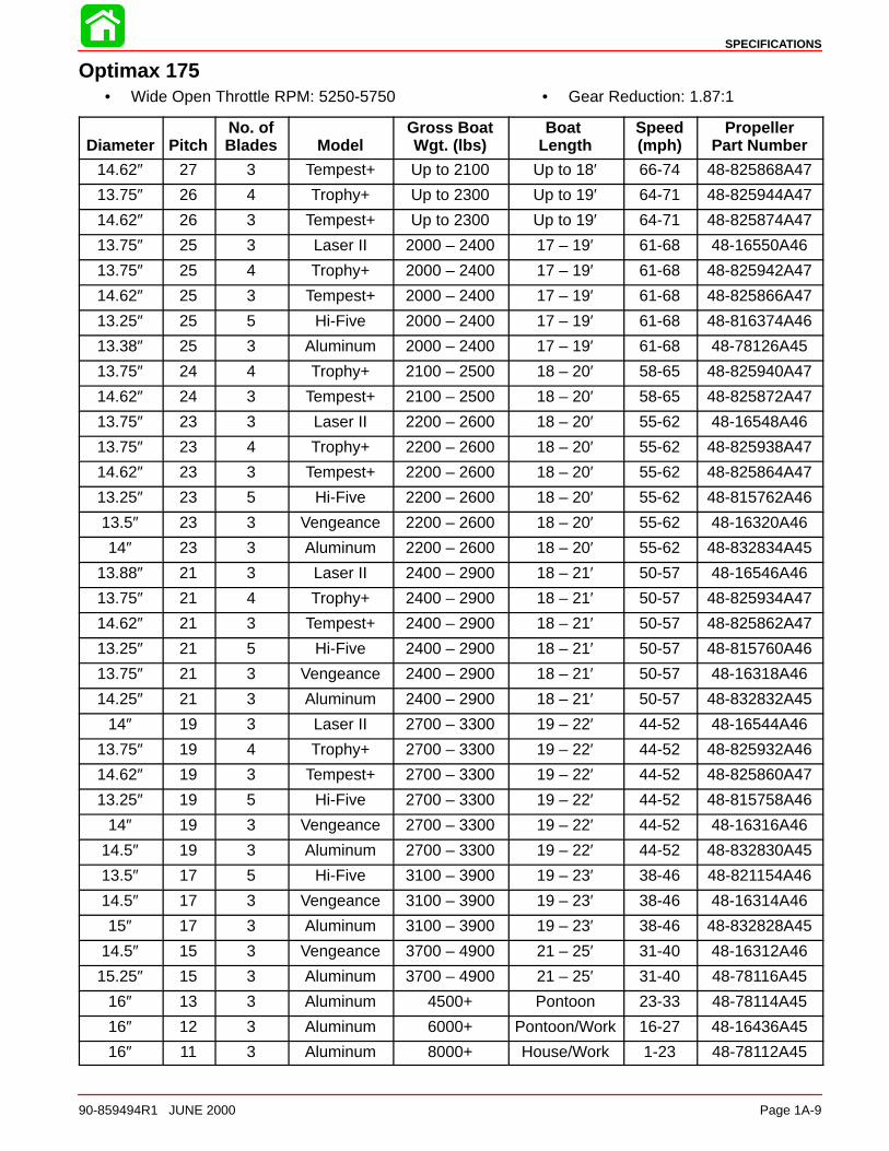
SPECIFICATIONS
90-859494R1 JUNE 2000 Page 1A-9
Optimax 175• Wide Open Throttle RPM: 5250-5750 • Gear Reduction: 1.87:1
Diameter PitchNo. ofBlades Model
Gross BoatWgt. (lbs)
Boat Length
Speed(mph)
PropellerPart Number
14.62″ 27 3 Tempest+ Up to 2100 Up to 18′ 66-74 48-825868A47
13.75″ 26 4 Trophy+ Up to 2300 Up to 19′ 64-71 48-825944A47
14.62″ 26 3 Tempest+ Up to 2300 Up to 19′ 64-71 48-825874A47
13.75″ 25 3 Laser II 2000 – 2400 17 – 19′ 61-68 48-16550A46
13.75″ 25 4 Trophy+ 2000 – 2400 17 – 19′ 61-68 48-825942A47
14.62″ 25 3 Tempest+ 2000 – 2400 17 – 19′ 61-68 48-825866A47
13.25″ 25 5 Hi-Five 2000 – 2400 17 – 19′ 61-68 48-816374A46
13.38″ 25 3 Aluminum 2000 – 2400 17 – 19′ 61-68 48-78126A45
13.75″ 24 4 Trophy+ 2100 – 2500 18 – 20′ 58-65 48-825940A47
14.62″ 24 3 Tempest+ 2100 – 2500 18 – 20′ 58-65 48-825872A47
13.75″ 23 3 Laser II 2200 – 2600 18 – 20′ 55-62 48-16548A46
13.75″ 23 4 Trophy+ 2200 – 2600 18 – 20′ 55-62 48-825938A47
14.62″ 23 3 Tempest+ 2200 – 2600 18 – 20′ 55-62 48-825864A47
13.25″ 23 5 Hi-Five 2200 – 2600 18 – 20′ 55-62 48-815762A46
13.5″ 23 3 Vengeance 2200 – 2600 18 – 20′ 55-62 48-16320A46
14″ 23 3 Aluminum 2200 – 2600 18 – 20′ 55-62 48-832834A45
13.88″ 21 3 Laser II 2400 – 2900 18 – 21′ 50-57 48-16546A46
13.75″ 21 4 Trophy+ 2400 – 2900 18 – 21′ 50-57 48-825934A47
14.62″ 21 3 Tempest+ 2400 – 2900 18 – 21′ 50-57 48-825862A47
13.25″ 21 5 Hi-Five 2400 – 2900 18 – 21′ 50-57 48-815760A46
13.75″ 21 3 Vengeance 2400 – 2900 18 – 21′ 50-57 48-16318A46
14.25″ 21 3 Aluminum 2400 – 2900 18 – 21′ 50-57 48-832832A45
14″ 19 3 Laser II 2700 – 3300 19 – 22′ 44-52 48-16544A46
13.75″ 19 4 Trophy+ 2700 – 3300 19 – 22′ 44-52 48-825932A46
14.62″ 19 3 Tempest+ 2700 – 3300 19 – 22′ 44-52 48-825860A47
13.25″ 19 5 Hi-Five 2700 – 3300 19 – 22′ 44-52 48-815758A46
14″ 19 3 Vengeance 2700 – 3300 19 – 22′ 44-52 48-16316A46
14.5″ 19 3 Aluminum 2700 – 3300 19 – 22′ 44-52 48-832830A45
13.5″ 17 5 Hi-Five 3100 – 3900 19 – 23′ 38-46 48-821154A46
14.5″ 17 3 Vengeance 3100 – 3900 19 – 23′ 38-46 48-16314A46
15″ 17 3 Aluminum 3100 – 3900 19 – 23′ 38-46 48-832828A45
14.5″ 15 3 Vengeance 3700 – 4900 21 – 25′ 31-40 48-16312A46
15.25″ 15 3 Aluminum 3700 – 4900 21 – 25′ 31-40 48-78116A45
16″ 13 3 Aluminum 4500+ Pontoon 23-33 48-78114A45
16″ 12 3 Aluminum 6000+ Pontoon/Work 16-27 48-16436A45
16″ 11 3 Aluminum 8000+ House/Work 1-23 48-78112A45


