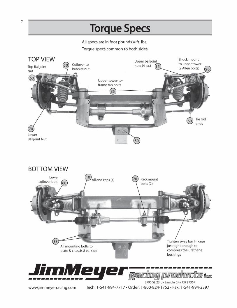
www.jimmeyerracing.com T ech: 1-541-994-7717 • Order: 1-800-824-1752 • Fax: 1-541-994-2397 2795 SE 23rd • Lincoln City, OR 97367 1953-62 Cor 1953-62 Cor 1953-62 Cor 1953-62 Cor 1953-62 Cor vette Bolt-In IFS Instructions vette Bolt-In IFS Instructions vette Bolt-In IFS Instructions vette Bolt-In IFS Instructions vette Bolt-In IFS Instructions Tabs on each upper tower weld to the chassis TOP VIEW BOTTOM VIEW Upper balljoints bolts in (4 bolts ea. side) Frame mounting brackets bolt to original chassis holes. (8 ea. side) Rubber bushed rack mounts Lower balljoint comes pressed-in Core support and sway bar bracket share common holes. Radiator core support Inner sway bar bolt threads into crossmember (both sides) Sway bar bracket bolts to lower coilover mounting bolt
Transcript
www.jimmeyerracing.com Tech: 1-541-994-7717 • Order: 1-800-824-1752 • Fax: 1-541-994-23972795 SE 23rd • Lincoln City, OR 97367
14 3/8 NC Nylock Nuts10 3/8 NC x 1 1/4 GR 8 Bolts4 3/8 NC x 1 1/2 GR8 Bolts Crossmember2 3/8 NC x 3/4 GR 8 Bolts
32 3/8 ID SAE Flat Washers
2 1/2 NC x 1 1/4 Bolts CoredaPstuN CN 2/12
4 1/2 SAE Flat Washers Adapter
1 Shock Spanner Wrench
Rack & Pinion Manual Steering 79-93 Mustang
Flaming River 9/16 x 26 spine #1503
1st thing to do is r1st thing to do is r1st thing to do is r1st thing to do is r1st thing to do is r ead over the entiread over the entiread over the entiread over the entiread over the entir e instre instre instre instre instr uctionsuctionsuctionsuctionsuctionspaying special attention to page 10paying special attention to page 10paying special attention to page 10paying special attention to page 10paying special attention to page 10
www.jimmeyerracing.com Tech: 1-541-994-7717 • Order: 1-800-824-1752 • Fax: 1-541-994-23972795 SE 23rd • Lincoln City, OR 97367
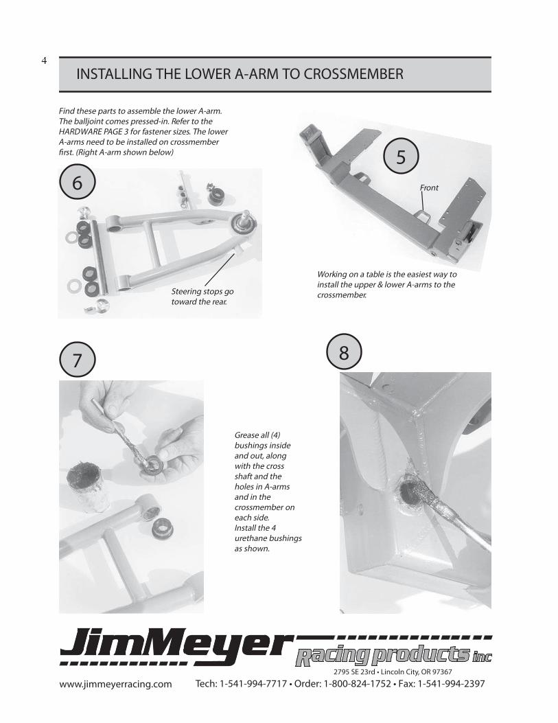
INSTALLING THE LOWER A-ARM TO CROSSMEMBER
6
5
4
Steering stops gotoward the rear.
Front
Grease all (4)bushings insideand out, alongwith the crossshaft and theholes in A-armsand in thecrossmember oneach side.Install the 4urethane bushingsas shown.
7 8
Find these parts to assemble the lower A-arm.The balljoint comes pressed-in. Refer to theHARDWARE PAGE 3 for fastener sizes. The lowerA-arms need to be installed on crossmember�rst. (Right A-arm shown below)
Working on a table is the easiest way toinstall the upper & lower A-arms to thecrossmember.
www.jimmeyerracing.com Tech: 1-541-994-7717 • Order: 1-800-824-1752 • Fax: 1-541-994-23972795 SE 23rd • Lincoln City, OR 97367
INSTALL LOWER A-ARM - Con’t
9
10
Use only a plastic mallet or rubber hammer to tap the shaftthrough the �rst 2 bushings. Then, install a 3/4-inch diameterwasher between the bushing and the crossmember. Continueto tap the pivot shaft through the crossmember.
As the pivot shaft meets the other side of thecrossmember, install another 3/4-inch diameter
washer. You should have one washer on each side ofthe crossmember.
1213
11
Continue tapping the shaft through the last 2 bush-ings, then stop with about 1/4-inch of shaft stickingout.
Use the aluminum capshaft screw (5/16NF X3/4 countersunk) to tap the shaft through thelast 1/4-inch.
5
www.jimmeyerracing.com Tech: 1-541-994-7717 • Order: 1-800-824-1752 • Fax: 1-541-994-23972795 SE 23rd • Lincoln City, OR 97367
INSTALL LOWER A-ARM - Con’t
INSTALLING UPPER A-ARMS TO CROSSMEMBER
1415
Install the aluminum end caps and Loctiteboth 5/16 NF countersunk �athead screwsin each end. Using an Allen wrench oneach end of the shaft (end caps) will keepthe shaft from turning.
Next, �nd the 5/16NC X 3/8 set screw, Locktite it andinstall as shown in lower A-arm cross shaft.
16
The longer arm of the upper A-arm goestoward front of the car.
Find these parts to assemble the upper A-arm. The balljoint drops in and is held byfour 1/4-20 X 3/4-inch bolts and Nylock nuts(torque to 15 ft. lbs.)
17Applygreaseon boththeupperA-armpivotbolts.Install atubular sleeve on each end. Use the shimsprovided between the sleeve & upper towerto eliminate any end play. Install bolts �ngertight until alignment.
18
19 20 21
Start by loading the rearA-arm bolt as shown, with1 sleeve, 1 thick washer &1 thin washer. Eliminate allfront-to-rear movementusing the washers asshims.
Like two gearsmeshingtogether,make surethe externalstar wash-ers mesh �at before tighten-ing the 2 Allen bolts to 60 ft.lbs. Start in middle as shown.
Left A-armshown
www.jimmeyerracing.com Tech: 1-541-994-7717 • Order: 1-800-824-1752 • Fax: 1-541-994-23972795 SE 23rd • Lincoln City, OR 97367
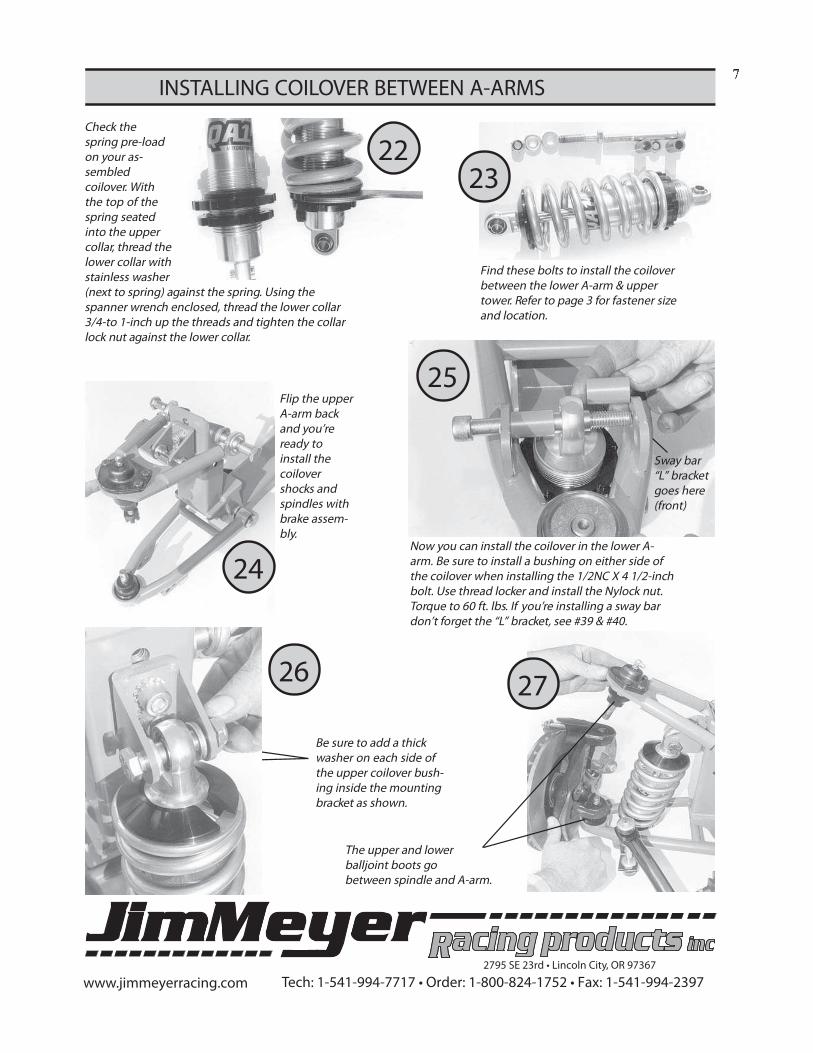
INSTALLING COILOVER BETWEEN A-ARMS7
Check thespring pre-loadon your as-sembledcoilover. Withthe top of thespring seatedinto the uppercollar, thread thelower collar withstainless washer(next to spring) against the spring. Using thespanner wrench enclosed, thread the lower collar3/4-to 1-inch up the threads and tighten the collarlock nut against the lower collar.
Find these bolts to install the coiloverbetween the lower A-arm & uppertower. Refer to page 3 for fastener sizeand location.
Now you can install the coilover in the lower A-arm. Be sure to install a bushing on either side ofthe coilover when installing the 1/2NC X 4 1/2-inchbolt. Use thread locker and install the Nylock nut.Torque to 60 ft. lbs. If you’re installing a sway bardon’t forget the “L” bracket, see #39 & #40.
2223
24
25
2627
Be sure to add a thickwasher on each side ofthe upper coilover bush-ing inside the mountingbracket as shown.
Sway bar“L” bracketgoes here(front)
Flip the upperA-arm backand you’reready toinstall thecoilovershocks andspindles withbrake assem-bly.
The upper and lowerballjoint boots gobetween spindle and A-arm.
www.jimmeyerracing.com Tech: 1-541-994-7717 • Order: 1-800-824-1752 • Fax: 1-541-994-23972795 SE 23rd • Lincoln City, OR 97367
8
INSTALLING RACK & STEERING ENDS
Don’t install the rack yet. You’ll be trimming thetie rod & that can be done on the bench. Seepage 3 for fastener sizes.
Tapered tie rod adapter goesinto the bottom of spindlesteering arm.
Note! The top of the 2 hatwashers face the rod end ball.
CCCCC lamp a 24-inch long bar to each rotor, andmeasure both front and rear of the rotor tomake sure they are parallel.
31
29
33
28
30
LLLLL ASTASTASTASTAST ,,,,,install the
rack andbolts as
shown. Torque to70 ft. lbs. Attach the
tie rod ends to steeringarms using the tapered tie
rod adapters.
32
NEXTNEXTNEXTNEXTNEXT ,,,,, subtract to �nd the di�erence betweenthese 2 measurements (#30& #32) and divideby 2. This will be the amount you need to cuto� each tie rod, plus 1 thread. Re-install therod ends to match the steering arm measure-ments.
MMMMMeasure center-to-center on thesteering armholes.
Re-install the rod ends to match the steeringarm measurements. Then, turn each rod endin about 1/2 turn for a 1/8” toe-in equivalent.
www.jimmeyerracing.com Tech: 1-541-994-7717 • Order: 1-800-824-1752 • Fax: 1-541-994-23972795 SE 23rd • Lincoln City, OR 97367
INSTALLING SWAY BAR & CORE SUPPORT
TO CROSSMEMBER
9
The anti sway barbushing bracketsbolt to the 2nd& 3rd inside framebolt holes. See #36
The core supportcrossmember bolts to thebottom of the new IFScrossmember legs. Theoutside bolts go in the frontoutside holes, in thecrossmember legs.
Threaded hole, this side.
Install the raisedend of the urethanebushings into theholes as shown.
The lower sway barmounting bracketbolts to the lowercoilover mountingbolt as shown.
The urethane bushedlink kit provided with theoptional sway bar goesthrough the bracket onthe front of the lower A-arm. The head of the boltshould point toward theground when loading theurethane bushings. Abushing goes on eachside of the sway bar andon each side of the A-armbracket.
40
www.jimmeyerracing.com Tech: 1-541-994-7717 • Order: 1-800-824-1752 • Fax: 1-541-994-23972795 SE 23rd • Lincoln City, OR 97367
REMOVING AND INSTALLING TIPS1�
The �rst thing to do is jack the carup high enough, on �at ground, toremove the old IFS. Start by dis-connecting the steering & brakelines. Next, with a �oor jack under
the IFS remove the 8 bolts on eachside holding the old IFS to chassis. Don’tforget to remove the 2 bolts holding the coresupport tab.
This is what the platform looks like on the bottom ofeach frame rail where the old IFS is attached.
Flange width on the frame rails varies from car to car.If you experience di�culty getting the crossmemberup against the bottom of the frame rail, you shouldmark on the �ange where the upper shock towersinterfere. Remove the crossmember and notch the�ange with a grinder to allow the tower to clear the�ange. Four 1/4-inch wide notches will do the job.
Another clearance headache is the lower motor mounttab that’s welded to the bottom of the frame. Grindaway enough of the mount to allow the newcrossmember to �t �at against the bottom of theframe.
The frame �ange may need to betrimmed for clearance where the lowersteering U-joint goes on the rack andpinion. The lower motor mount andframe tab may need to be trimmed forsteering shaft clearance.
As you jack theentire assembly upunder the chassis,you’ll need tomark the innerfender panels onboth sides. Trimthe �berglasswhere necessary.
41
42 43
44
45
The upper tower tabs weldto the frame on both sides.See page 3 for fastener size.
www.jimmeyerracing.com Tech: 1-541-994-7717 • Order: 1-800-824-1752 • Fax: 1-541-994-23972795 SE 23rd • Lincoln City, OR 97367
11
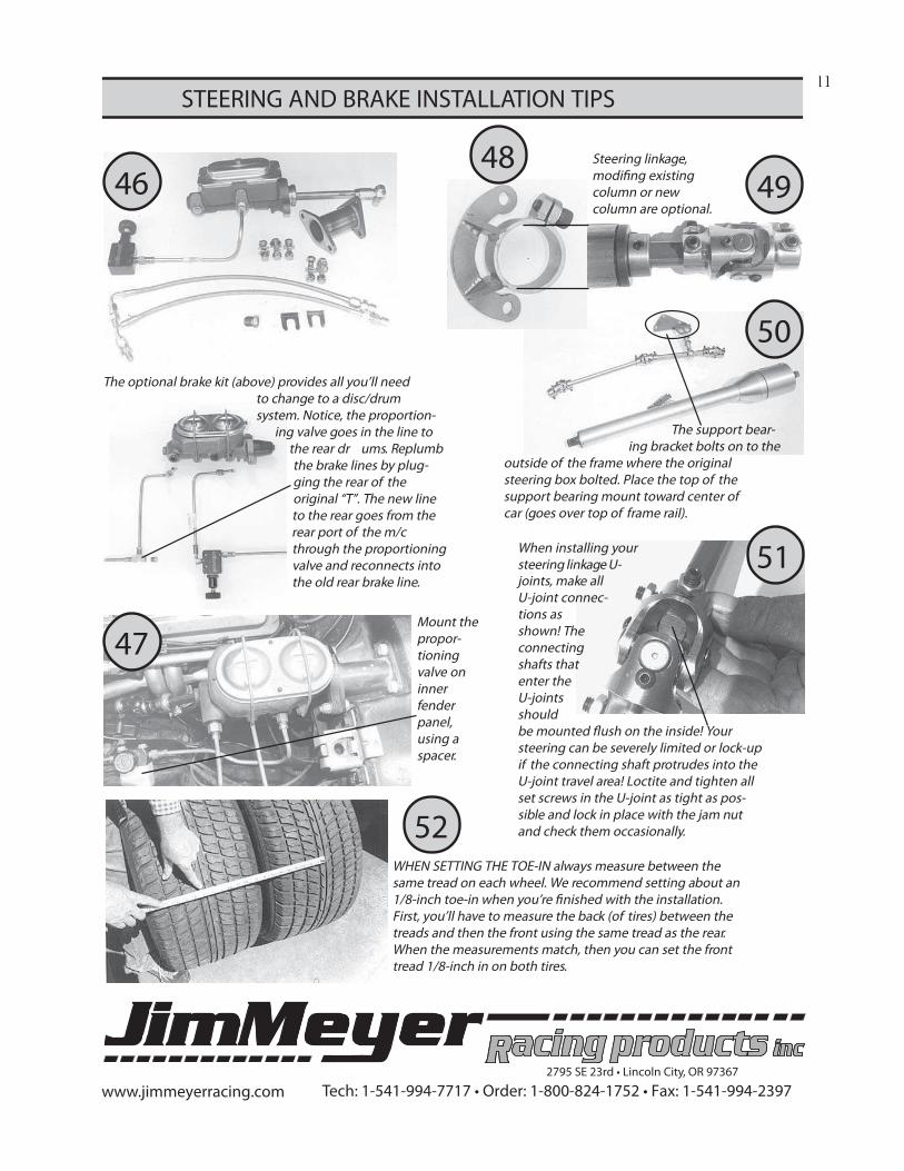
STEERING AND BRAKE INSTALLATION TIPS
The optional brake kit (above) provides all you’ll needto change to a disc/drumsystem. Notice, the proportion-
ing valve goes in the line tothe rear dr ums. Replumbthe brake lines by plug-ging the rear of theoriginal “T”. The new lineto the rear goes from therear port of the m/cthrough the proportioningvalve and reconnects intothe old rear brake line.
Steering linkage,modi�ng existingcolumn or newcolumn are optional.
When installing yoursteering linkage U-joints, make allU-joint connec-tions asshown! Theconnectingshafts thatenter theU-jointsshouldbe mounted �ush on the inside! Yoursteering can be severely limited or lock-upif the connecting shaft protrudes into theU-joint travel area! Loctite and tighten allset screws in the U-joint as tight as pos-sible and lock in place with the jam nutand check them occasionally.
47
46 49
51
50
WHEN SETTING THE TOE-IN always measure between thesame tread on each wheel. We recommend setting about an1/8-inch toe-in when you’re �nished with the installation.First, you’ll have to measure the back (of tires) between thetreads and then the front using the same tread as the rear.When the measurements match, then you can set the fronttread 1/8-inch in on both tires.
52
The support bear-ing bracket bolts on to the
outside of the frame where the originalsteering box bolted. Place the top of thesupport bearing mount toward center ofcar (goes over top of frame rail).
Mount thepropor-tioningvalve oninnerfenderpanel,using aspacer.
48
www.jimmeyerracing.com Tech: 1-541-994-7717 • Order: 1-800-824-1752 • Fax: 1-541-994-23972795 SE 23rd • Lincoln City, OR 97367
JIM MEYER RACING PRODUCTSJIM MEYER RACING PRODUCTSJIM MEYER RACING PRODUCTSJIM MEYER RACING PRODUCTSJIM MEYER RACING PRODUCTS
WA������ �I�������I o �Ia c��I I� � k� �s��� I�a b � �o�� � ba � ��I�
e� � Ic � I �s I�������I �I� ��� � � ���I o S�S���S��� S�S���S� �� �