146


FOREWORD This manual has been prepared to give information and guidance to the Drain Commissioner’s personnel and their consultants and contractors who are responsible for Soil Erosion and Sedimentation Control (SESC) during earth change activities conducted under their direction as an Authorized Public Agency (APA) under Section 324.9110 of Part 91, Soil Erosion and Sedimentation Control, of the Natural Resources and Environmental Protection Act, 1994 PA 451, as amended. If a Drain Commissioner is not an APA, he/she must submit a SESC plan and apply for a SESC permit from the appropriate county or municipal enforcing agent regardless of whether he/she is following the guidelines set forth in the manual.
ACKNOWLEDGEMENTS In 2017, this Manual was revised under the direction of the MACDC Executive Committee, which consisted of the following people:
Amy Berry, MDEQ Water Resources Division Brad Boomstra, P.E., Kent County Drain Commissioner’s Office Alan Boyer, P.E., LSG Engineers and Surveyors Mark Cavanaugh, Hanes Geo Components Doug Enos, Midland County Drain Commissioner Amy Lounds, MDEQ Water Resources Division Chris Mattson, P.E., Spicer Group, Inc. Teri McCormack, Spicer Group, Inc. Jon Morrison, P.E., Clinton County Deputy Drain Commissioner Joe Parman, Van Buren County Drain Commissioner Larry Protasiewicz, P.E., Spicer Group, Inc. Brandie Stefanski, MDEQ Water Resources Division June Williams, Spicer Group, Inc.
The 2006 version of this document was developed under the direction of a MACDC Special Task Force consisting of the following people; Janis Bobrin, President MACDC; Pat Lindemann, Vice President MACDC; Abby Eaton, Michigan Department of Agriculture; Dick Mikula, Michigan Department of Environmental Quality; Hope Croskey, Spicer Group, Inc.
Credit also belongs to the Michigan Department of Technology, Management and Budget and the Michigan Department of Transportation whose staff provided digital copies of their SESC Procedures Manuals, including the digital graphic files, which were used extensively for and during development of this manual.
In addition, we wish to acknowledge the contributions of Spicer Group who went above and beyond to ensure completion of the revisions to this document, which was approved by the Department of Environmental Quality on February 3, 2018.
ii Rev. 2018
TABLE OF CONTENTS Page
SECTION 1 – Program Guidelines
INTRODUCTION .............................................................................................. 1
COMMITMENT ................................................................................................ 2
NOTIFICATION OF PROPOSED EARTH CHANGE ....................................... 3
SESC CERTIFICATE OF TRAINING ............................................................... 3
PLANNING PHASE .......................................................................................... 4
DESIGN PHASE .............................................................................................. 5
PART 31 NOTICE OF COVERAGE ................................................................. 5
CONTRACT DOCUMENTS ............................................................................. 6
INSPECTION AND WRITTEN DOCUMENTATION ......................................... 6
CORRECTIVE ACTIONS ................................................................................. 8
FORMS ............................................................................................................ 8
SECTION 2 – MACDC Keying System
EROSION CONTROL MEASURES ............................................................... 10
ROUTINE MAINTENANCE ACTIVITIES ....................................................... 13
SECTION 3 – Erosion Control Measures
1. SEEDING ................................................................................................... 15
2. MULCH ...................................................................................................... 21
3. SODDING .................................................................................................. 24
4. TREES, SHRUBS, VINES AND GROUNDCOVER ................................... 26
5. PERIMETER SEDIMENT CONTROL MEASURES ................................... 28
6. CATCH BASIN ........................................................................................... 32
7. STORM DRAIN INLET PROTECTION ...................................................... 35
8. LIVE STAKING ........................................................................................... 37
9. VEGETATION REMOVAL WITHOUT GRUBBING .................................... 40
10. SOIL BINDING POLYMERS .................................................................... 42
11. POLYMER OR BIOPOLYMER FLOCCULANTS ..................................... 45
12. PLASTIC SHEETING OR GEOTEXTILE COVER ................................... 48
13. SLOPE STABILIZATION .......................................................................... 50

iii Rev. 2018
14. SLOPE ROUGHENING AND SCARIFICATION ...................................... 53
15. RIPRAP .................................................................................................... 54
16. RIPRAP TOE OF SLOPE ........................................................................ 58
17. BRUSH BUNDLES ................................................................................... 61
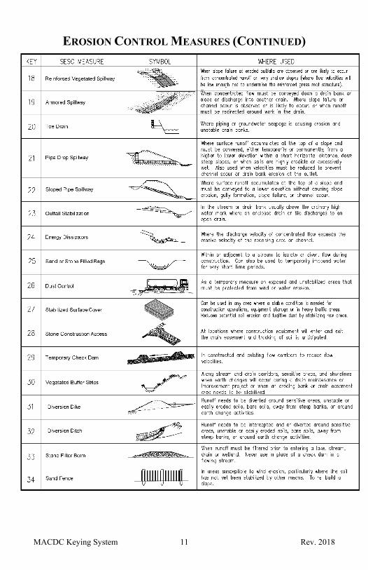
18. REINFORCED VEGETATED SPILLWAY ................................................ 64
19. ARMORED SPILLWAY ............................................................................ 67
20. TOE DRAIN .............................................................................................. 69
21. PIPE DROP SPILLWAY ........................................................................... 70
22. SLOPED PIPE SPILLWAY....................................................................... 72
23. OUTFALL STABILIZATION ...................................................................... 75
24. ENERGY DISSIPATORS ......................................................................... 77
25. SAND OR STONE FILLED BAGS ........................................................... 81
26. DUST CONTROL ..................................................................................... 83
27. STABILIZED SURFACE COVER ............................................................. 85
28. STONE CONSTRUCTION ACCESS ....................................................... 87
29. TEMPORARY CHECK DAM .................................................................... 90
30. VEGETATED BUFFER STRIPS .............................................................. 94
31. DIVERSION DIKE .................................................................................... 97
32. DIVERSION DITCH ................................................................................. 99
33. STONE FILTER BERM .......................................................................... 101
34. SAND FENCE ........................................................................................ 102
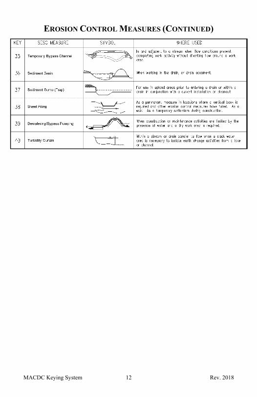
35. TEMPORARY BYPASS CHANNEL ....................................................... 104
36. SEDIMENT BASIN ................................................................................. 107
37. SEDIMENT SUMP (TRAP) .................................................................... 110
38. SHEET PILING ...................................................................................... 113
39. DEWATERING/BYPASS PUMPING ...................................................... 115
40. TURBIDITY CURTAIN ........................................................................... 118
SECTION 4 – Routine Maintenance Activities
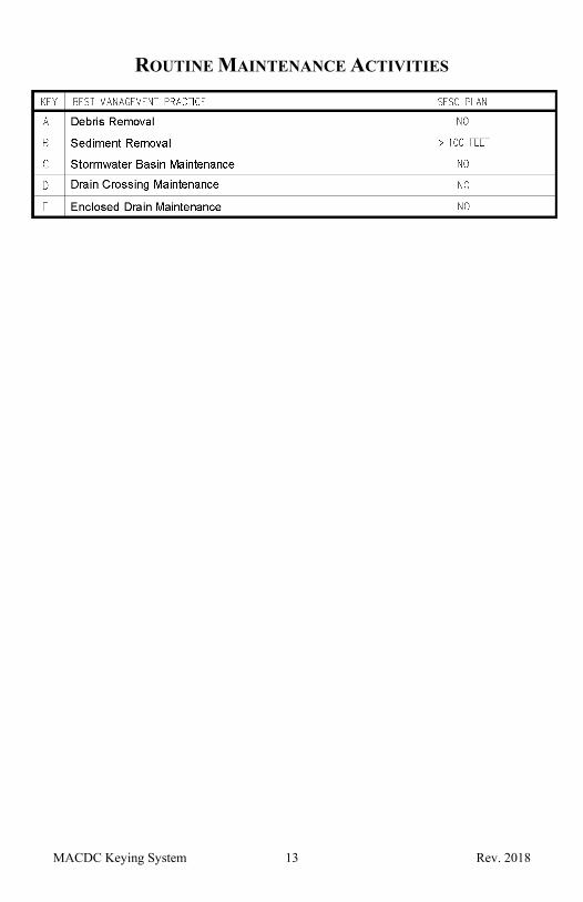
A. DEBRIS REMOVAL ................................................................................. 121
B. SEDIMENT REMOVAL ............................................................................ 122
C. STORMWATER BASIN MAINTENANCE ................................................ 125

iv Rev. 2018
D. DRAIN CROSSING MAINTENANCE ...................................................... 127
E. ENCLOSED DRAIN MAINTENANCE ...................................................... 128
SECTION 5 – Part 91 and Administrative Rules
SECTION 6 – Glossary
*Subscript numerals found in the text are references to other measures.

SECTION 1 – Program Guidelines

Program Guidelines 1 Rev. 2018
INTRODUCTION The goal of the Drain Commissioner is to implement Soil Erosion and Sedimentation Control (SESC) measures that are cost effective; will effectively minimize erosion and off-site sedimentation; and will protect the soil, water, and other natural resources when earth change activities are conducted under their authority. Achieving this goal is fundamental to the efficiency and economical service life of drainage and stormwater facilities, and lake level control structures.
A copy of this manual, which includes Part 91, SESC, of the Natural Resources and Environmental Protection Act, 1994 PA 451, as amended (Part 91), and the associated administrative rules (Rules) promulgated under Part 91 will be made available to the Drain Commissioner’s staff and their contracted personnel who are expected to understand and implement the contents of this manual. This SESC Procedures Manual is adopted by the Drain Commissioner and details the SESC measures that will be utilized during all earth change activities, including maintenance, construction, and restoration activities as an Authorized Public Agency (APA).
Individual Part 91 permits are not required for designated APAs. However, all earth change activities must meet Part 91 and Rule requirements. To maintain this APA status, earth change activities regardless of size or location must be conducted in accordance with these approved SESC procedures unless a variance is requested by the APA and granted by the Michigan Department of Environmental Quality (MDEQ or DEQ). As standards and/or techniques for SESC evolve, this manual will require modifications that must be approved by the MDEQ prior to formal adoption. Having the APA designation does not exempt the Drain Commissioner from obtaining all other applicable federal, state, and local permits.
It should be noted that some practices in this manual may require a permit under Part 301, Inland Lakes and Streams, and/or Part 303, Wetlands Protection, of the NREPA. Construction activities in wetlands, lakes and streams may require a permit from the DEQ. Streams and wetlands should be noted as part of any SESC plan and taken into account during the project to ensure BMPs are being utilized. For information on permitting specific to these SESC Measures, as well as other information, please refer to the ‘Permits for County Drain Activities’ link on the DEQ Inland Lakes and Streams Protection website.
Permits under Parts 301 and 303 are generally not required for maintenance of a drain that either was legally established and constructed pursuant to the Drain Code of 1956 before January 1, 1973, or was constructed or modified under a permit issued under Part 301 and/or 303. However, this exemption from permitting does not apply to legally established drains constituting mainstream portions of certain natural watercourses identified in rule, or to activities that result in additional wetland drainage or conversion. For these permitting exemptions, “Maintenance of a drain" means the physical preservation of the location, depth, and bottom width of a drain and appurtenant structures to restore the function and approximate capacity of the drain as constructed or modified and includes the following if performed with best management practices. For

Program Guidelines 2 Rev. 2018
additional information on these laws and permit processing refer to www.michigan.gov/wetlands , www.michigan.gov/deqinlandlakes or www.michigan.gov/jointpermit .
COMMITMENT To maintain the APA designation, the Drain Commissioner is committed to comply with the SESC Procedures while undertaking all earth change activities. This manual presents procedures for conducting earth change activities and implementing SESC measures that fulfill this commitment through stabilization of disturbed soils and preventing off-site sedimentation (downstream of the project limits or outside of the drain easement). Part 91 defines stabilization as the establishment of vegetation or the proper placement, grading, or covering of soil to ensure its resistance to soil erosion, sliding, or other earth movement. The following basic principles will be included in the planning, design, specification, construction, and inspection of drain maintenance and improvement projects that include earth change activities:
1. Inspect and maintain drains, prioritizing maintenance activities that emphasize preventive measures and procedures that will minimize soil erosion and the resulting sedimentation, including but not limited to:
(a) Disturbing the least amount of soil for the shortest period of time. (b) Encourage and maintain vegetated buffer strips whenever possible. (c) Repair blowouts, seeps and slumped areas along a drain as soon
as possible. (d) Evaluate if dredging only specific reaches of a drain would provide
effective drainage rather than dredging the entire drain. (e) Remove obstructions and sediment which are causing scouring and
other erosive forces. (f) Establish stable streambank slopes that can withstand anticipated
flow at non- erosive velocities.
2. In non-emergency situations, conduct earth change activities during the time of year and flow conditions that will minimize erosion and the resulting sedimentation.
3. Provide control measures that will effectively control erosion of, and sediment from, the exposed area, and stabilize disturbed areas, except for actively cultivated agricultural fields, either temporarily or permanently, as soon as possible. Seed, apply mulch when necessary, or otherwise stabilize disturbed drain banks daily. During hydraulic or mechanical dredging, spread spoils outside of wetland areas in a manner that will not impede floodplain function. To prevent erosion and ditch bank surcharge, seed or otherwise stabilize spread spoils within 5 days unless spoils are being spread in actively cultivated agricultural fields. If spoils will be spread at a later date, either place spoils where surface runoff from the spoil piles will drain away from the drain; or
Program Guidelines 3 Rev. 2018
seed, apply mulch when necessary, or otherwise stabilize spoil piles within 5 days.
4. During the non-growing season when vegetation cannot be established, additional control measures will be implemented to ensure the prevention of soil erosion and off-site sedimentation. These measures may include, but are not limited to, silt fence, erosion control blankets, various geosynthetic products, polyacrylamides, and/or other BMPs that will ensure the temporary stabilization of the soil until the next growing season when permanent vegetation can be established. The increased need and cost for additional SESC measures during the non-growing season will be considered in planning for projects that start or finish in late fall or winter.
5. Install and maintain adequate, temporary or permanent, SESC measures prior to commencing other earth change activities. Temporary SESC measures shall be installed and functioning prior to commencement of earth change activities and shall be removed only after permanent SESC measures are in place, functioning, and the site has been stabilized.
6. Where feasible, design channel and drain bank slopes that will be easily stabilized for the site-specific soil types and anticipated flow velocities.
7. Select a route and course for new drains that will achieve project objectives while minimizing soil erosion, taking into consideration areas with unstable soils and wetland complexes. Establish adequate rights-of-way for construction and future maintenance operations.
8. Minimize erosion and control sediment at points of concentrated flow or grade changes utilizing appropriately designed and installed SESC measures.
NOTIFICATION OF PROPOSED EARTH CHANGE As an APA, individual permits are not required from the applicable County or Municipal Enforcing Agency. However, Part 91 requires an APA to notify the applicable county or municipal enforcing agency of each proposed earth change that would have required a SESC permit [See Rule 323.1706 (4)]. The complete list of County and Municipal Enforcing Agencies is available on the MDEQ website
SESC CERTIFICATE OF TRAINING Section 324.9110 (4) (b) of Part 91 requires those individuals with decision-making authority who are responsible for administering the Drain Commissioner’s SESC Program have current certificates of training under Section 324.9123. Therefore, all Drain Commissioner personnel who make decisions regarding the

Program Guidelines 4 Rev. 2018
design, inspection, or implementation of SESC measures must have a valid Certificate of Training. A certificate can be obtained by completing the MDEQ's SESC training class or the self-study training and passing the final exam.
PLANNING PHASE Effective erosion and sediment control begins with planning, including designing and locating projects to best meet each project objective while minimizing the potential for erosion and avoiding sensitive and high erosion potential areas when feasible. Installation and maintenance of properly designed SESC measures and conducting routine maintenance activities prevent erosion and control sediment. Other activities typically utilized in maintenance activities are recognized as design elements or Best Management Practices (BMPs), subject to additional design and engineering. This manual provides procedures for the design, implementation, and maintenance of individual SESC measures, as well as information for developing SESC plans.
Several of the SESC measures identified in Sections 3 of this manual involve earthwork that would normally require a SESC plan prior to implementation. However, a SESC plan is not required for measures requiring earthwork as long as they are installed in accordance with this manual’s guidelines. Any deviation from the guidelines will require that a SESC plan be developed prior to implementation.
When a drain activity or SESC measure requires a SESC plan, a plan shall be developed to effectively reduce accelerated soil erosion and sedimentation. The plan shall identify factors that may contribute to soil erosion or sedimentation or both. The plan shall include, but not be limited to, the following:
1. A map or maps at an adequate scale to illustrate the:
(a) Extent of the earth change activities; (b) Existing and any proposed drain locations; (c) Proximity of proposed earth change to lakes, streams, wetlands or
drains; (d) Predominant land features; and (e) Contour intervals or slope descriptions.
2. A soils survey and the associated soil types or a written description of the general soil types of the exposed land area contemplated for the earth change.
3. Details for proposed earth changes include all of the following:
(a) A description and the location of the physical limits of each proposed earth change.
(b) A description and the location of all existing and proposed on-site drainage and dewatering facilities.
(c) The timing and sequence of each proposed earth change. (d) The location and description for installing and removing all
proposed temporary SESC measures.

Program Guidelines 5 Rev. 2018
(e) A description and the location of all proposed permanent SESC measures.
(f) Proposal for continued maintenance of all permanent SESC measures.
DESIGN PHASE It is the responsibility of the Drain Commissioner to ensure that a project is designed correctly. A staff engineer or engineering consultant and/or qualified professionals shall be utilized during the design phase when required in the details for a specific SESC measure. The project design should minimize adverse impacts to areas with high erodible soils or areas next to lakes, streams, or wetlands while incorporating project specific permit requirements. Those responsible for recommending SESC measures need to specify control measures that are practical, reasonable and effective during the construction phase of a project to achieve adequate SESC. The design plans, included as part of the contract documents, must clearly indicate the location and installation details for all appropriate SESC measures.
PART 31 NOTICE OF COVERAGE Construction activities which disturb one or more acres of land and have a point source discharge of stormwater to surface waters of the state are required to obtain a National Pollutant Discharge Elimination System (NPDES) permit from the DEQ.
The DEQ has adopted a process called "Permit-by-Rule" (Rule 2190, promulgated under Part 31, Water Resource Protection, of the National Resource and Environmental Protection Act (NREPA)), for issuing the necessary stormwater coverage. Permit-by-Rule "streamlines" the permitting process and is dependent upon the applicant first obtaining coverage under Part 91, Soil Erosion and Sedimentation Control (SESC), of the NREPA (Part 91), i.e., obtaining an SESC permit from the appropriate Part 91 permitting agency or being designated an Authorized Public Agency (APA).
For sites disturbing 1 to 5 acres, the applicant/permittee receives automatic stormwater coverage upon the applicant obtaining a Part 91 permit (or undertaking the project as an APA). Although the coverage is automatic, the permittee must comply with the requirements of Permit- by-Rule.
For sites disturbing 5 or more acres, the applicant/permittee must obtain a Part 91 permit (or undertake the project as an APA) and submit an application for Notice of Coverage (NOC) to the DEQ via the DEQ web-based permitting and compliance database, MiWaters. Along with the NOC application, the applicant/permittee must submit a copy of the SESC permit (or APA information), approved SESC plan, site location map, and the permit fee.
The permittee must follow the requirements of Permit-by-Rule. Permit-by-Rule requires compliance with the SESC permit issued under Part 91 or the approved procedures and also requires SESC measures to be inspected weekly and within 24 hours of a precipitation event that causes a discharge from the site significant

Program Guidelines 6 Rev. 2018
rain event by a certified storm water operator. The certification materials and testing dates are available in most DEQ district offices.
CONTRACT DOCUMENTS As an APA, the Drain Commissioner is ultimately responsible for conducting and documenting SESC inspections and assuring that all earth change activities undertaken by their staff or contractors working under their APA designation meet the requirements of Part 91, the Rules, and this Manual. Therefore, the Drain Commissioner shall ensure that all contract documents include a clear description of the contractor’s responsibilities including: compliance with this manual, by reference; installation, and ongoing monitoring and maintenance of site specific SESC measures by the contractor until all disturbed areas are stabilized and temporary SESC measures are removed. The contract document must provide the ability to adapt, adjust and add SESC measures necessary to maintain a level of SESC required to comply with Part 91, the Rules, this manual, and other project specific permit requirements.
Contract documents must clearly state the authority of the Drain Commissioner to enforce compliance with Part 91, the Rules, and this manual, and the consequences for noncompliance. To assist with contractor compliance, contract documents should also include, but not be limited to, the following:
1. Acquisition of cash, a certified check, an irrevocable bank letter of credit or a surety bond acceptable to the county in the amount sufficient to assure the installation and completion of such protective or corrective measures, and/or site restoration, as may be required by the Drain Commissioner to assure compliance with Part 91, the Rules, and this manual.
2. The ability of the Drain Commissioner to expend these funds if, in the opinion of the Drain Commissioner, the site may result in or contribute to soil erosion or sedimentation of adjacent properties or to the waters of the state, if the SESC measures required in the SESC plan are not properly installed or maintained, or if the site is not in compliance with Part 91, the Rules or this manual.
3. The ability of the Drain Commissioner to assess costs for site restoration, site stabilization, and/or restore or repair off-site damages if the contractor does not comply with their contract or Part 91, the Rules or this manual.
INSPECTION AND WRITTEN DOCUMENTATION Inspections and written documentation are not required for an earth change activity of a minor nature that is stabilized within 24-hours of the initial earth disturbance. However, inspections and written documentation are required for all other earth change activities.
Program Guidelines 7 Rev. 2018
Adequate inspections and follow-up maintenance provide the APA with the tools necessary to meet their ultimate responsibility to minimize soil erosion and off-site sedimentation. The inspection frequency is outlined in the Maintenance Category of each individual procedure and uses terms such as routinely or periodically. These generalized terms provide the needed flexibility in determination of an adequate inspection schedule based on site conditions such as soil types and moisture content; time of year; flow conditions; anticipated weather, etc.
Routine inspections are required until the site is stabilized with permanent SESC measures. The frequency of routine inspections must consider factors such as seed germination period; weather conditions including wind and precipitation; and anticipated vehicular and pedestrian traffic. Periodic inspections would be required for permanent SESC measures that were stabilized when installed but may need to be monitored occasionally to assure continued functionality as designed. High traffic areas that may be susceptible to vandalism or vegetation removal in an area where flow may be constricted resulting in flooding of adjacent properties are examples of areas needing periodic inspections.
Required inspections will be conducted by the Drain Commissioner’s personnel, or their contracted inspector, at an adequate frequency to assure minimization of soil erosion and off-site sedimentation and will be coordinated with the contractor’s work schedule to assure timeliness and to obtain maximum inspection benefits. All inspections will be conducted and documented by a person with a valid SESC Certificate of Training from the MDEQ. The completed Inspection Form, provided in Section 1.6, will document at a minimum the following:
1. Date of inspection.
2. Name of inspector.
3. Name of engineer, project manager, and contractor or responsible APA personnel.
4. General weather conditions during inspection and previous 48 hours.
5. Are SESC measures installed and/or stabilized per plan and SESC details?
6. Are SESC measures effectively controlling erosion and sediment?
7. Note deficiencies such as a SESC measure is ineffective, needs maintenance or has failed or a slope stabilization failure has occurred.
8. Other relevant information such as photographs.
If no deficiencies are found, a report is still required to be completed and placed on file. If deficiencies are found, the inspector will initiate the following actions to correct the deficiencies:
1. Note the deficiencies, including maintenance requirements and corrective actions, on the Inspection Form being specific about the type and location of the deficiencies.

Program Guidelines 8 Rev. 2018
2. Advise the contractor or responsible Drain Commissioner personnel of the deficiencies and provide sufficient verbal or written instructions to ensure a complete understanding of the deficiencies and the necessary corrective actions. These instructions may include a work order, a revised SESC plan, or reference to specific SESC measures.
3. Specify an appropriate timeframe with which to complete the corrective actions. Deficiencies which are determined to be of an emergency nature must be corrected within 24 hours. Examples of deficiencies deemed an emergency are sedimentation of the waters of the state and erosion of or sediment on a roadway which could jeopardize public safety. Deficiencies which are not considered an emergency should be corrected within 5 days.
CORRECTIVE ACTIONS Contracted Projects
In the event that the Drain Commissioner personnel, or their contracted inspector, is unsuccessful in getting a contractor to perform corrective actions, the Drain Commissioner will assume responsibility for ensuring that SESC corrective actions are implemented. The following progressive steps shall be taken if a contractor fails to comply with their contract or Part 91 regulations.
1. Issue or reissue a work order describing the work to be completed by the contractor specifying a completion date.
2. Issue a Notice of Non-Compliance with Contract Requirements for failure to respond to SESC corrective actions in a timely manner.
3. Contract with another specialty contractor to complete the required corrective actions to ensure compliance with regulations.
4. Prepare and place on file a Contractor Evaluation to document the contractor’s inability to meet contract obligations and implementation of required SESC measures.
In-House Projects
SESC corrective actions will be implemented and, when necessary, the appropriate disciplinary action will be taken.
FORMS The following forms shall be used for the administration of the SESC Program.
1. MEA/CEA Notification Form
2. SESC Inspection Log
3. SESC Plan Checklist

SECTION 2 – MACDC Keying System

MACDC Keying System 10 Rev. 2018
EROSION CONTROL MEASURES
MACDC Keying System 11 Rev. 2018
EROSION CONTROL MEASURES (CONTINUED)
MACDC Keying System 12 Rev. 2018
EROSION CONTROL MEASURES (CONTINUED)
MACDC Keying System 13 Rev. 2018
ROUTINE MAINTENANCE ACTIVITIES
SECTION 3 – Erosion Control Measures

Erosion Control Measures 15 Rev. 2018
1. SEEDING When Bare soil is exposed to erosive forces from wind and/or
water. Why A cost-effective way to prevent erosion by protecting
the soil from raindrop impact, flowing water and wind. Vegetation binds soil particles together with a dense
root system, increasing infiltration thereby reducing runoff volume and velocity.
Where On all disturbed areas except where non-vegetative stabilization measures are being used or where seeding would interfere with agricultural activity.
Scheduling Daily during drain maintenance activities while exposed soil is still moist.
During the recommended temporary and permanent seeding dates outlined below.
Dormant seeding is acceptable.How 1. Site Assessment. Determine site physical
characteristics including available sunlight, slope, adjacent topography, local climate, proximity to sensitive areas or natural plant communities, and soil characteristics such as natural drainage class, texture, fertility and pH.
2. Seed Selection. Use seed with acceptable purity and germination tests that are viable for the planned seeding date. Seed that has become wet, moldy or otherwise damaged is unacceptable. Select seed depending on, location and intended purpose. A mixture of native species for permanent cover may provide some advantages because they have coevolved with native wildlife and other plants and typically play an important function in the ecosystem. They are also adapted to the local climate and soil if properly selected for site conditions; can dramatically reduce fertilizer, lime and maintenance requirements; and provide a deeper root structure. When re-vegetating natural areas, introduced species may spread into adjacent natural areas, native species should be used. Noxious or aquatic nuisance species shall not be used (see list below). If seeding is a temporary soil erosion control measure select annual, non-aggressive species such as annual rye, wheat, or oats. See USDA-NRCS-MICH "Critical Area Planting Guide 342-1" for specific seeding rates by species.
3. Site Preparation. Final grade or shape area to be seeded. Remove large clods, rocks, tree roots, etc. that will interfere with seeding. A spring tooth drag, field tiller, disk or other suitable equipment may be used. When feasible, replace the topsoil after grading. If soils are compacted, scarify14 or rake seedbed to a

Erosion Control Measures 16 Rev. 2018
minimum depth of 3 inches and roughen slopes steeper than 3 horizontal to 1 vertical. If needed, divert concentrated flows away from seeded areas until vegetation is established.
4. Soil Amendments. Properly sited native vegetation should not require fertilization and, in such instances, fertilizing may promote competition from unwanted species at the expense of natives. Do not apply nitrogen for warm season mixes. If fertilizer is needed, fertilize with a low or no phosphorus fertilizer when near water, and/or add lime only when necessary for proper establishment and maintenance of vegetation. Conduct a soil test to determine required soil amendments if having difficulties with vegetation establishment. See Soil Amendments Table below.
5. Seeding. Apply seed as soon as possible, preferably daily during drain maintenance activities while the soil is still moist, but within 5 days, after final grading, shaping, and/or seedbed preparation by hand broadcasting, hydroseeding, or using mechanical drills following seeding dates outlined below. Water as needed or possible for successful germination. Apply temporary seeding to disturbed areas within 5 days if final grading and permanent seeding will be delayed for more than 5 days. Apply temporary seed daily to dredged spoil piles that will be flattened at a later date if they do not slope away from the drain except where they will interfere with plowing tilling or the harvesting of crops. Seed streambanks daily and other disturbed areas within 5 days.
6. Dormant fall seeding. In late fall after the soil temperature remains consistently below 50oF prior to the ground freezing. No seed germination will take place until spring; therefore, mulch2 or another stabilization technique may be required to prevent erosion and off-site sedimentation. A cool season annual grass may be added in an attempt to have some fall growth.
7. Dormant winter seeding. Apply seed daily to disturbed areas and dredged spoil piles before they freeze. Seed will germinate in the early spring.
8. Mulch2 is recommended for dormant fall and winter seeding and on all slopes, unstable soils, heavy clay soils and all areas adjacent to wetlands, streams, drains, or sensitive areas and should be applied immediately after seeding.
9. Protect seeded areas from pedestrians and vehicular traffic.
Maintenance Inspect newly seeded areas subsequent to anticipated germination date and after each significant rainfall event that produces runoff until areas are stabilized.

Erosion Control Measures 17 Rev. 2018
Repair eroded areas, applying supplemental seed1, mulch2 and water as needed.
If seed does not establish, conduct soil tests, amend soils as needed, and reapply seed and/or mulch during the recommended growing season.
To assist in the establishment of native species, remove unwanted competing vegetation in the first year.
Mowing during establishment can be used periodically to discourage weeds.
Limitations Soil is susceptible to erosion until seedbeds are established. Sites may require re-seeding.
Seasonal limitations include excessive heat or early frost/freeze and adequate moisture for germination and early growth.
May not be appropriate in high traffic areas. Native species may be costly; however, the increased
awareness of the benefits of planting native species is beginning to reduce their price and increase their availability.
TEMPORARY SEEDING DATES
Seed Type Lower Peninsula south of US 10
Lower Peninsula north of US 10
Upper Peninsula
Amount (lbs. per)
1000 sq. ft.
Acre
Oats, Barley April 1 - Sept. 15
April 15 - Aug. 1
May 1- Aug. 1
2 96
Cereal Rye Aug. 1 - Oct. 15
Aug. 1 - Oct. 10
Aug. 1 - Nov. 1
3 120
Wheat Sept. 20 - Oct. 15
Sept. 10 - Oct. 10
Sept. 10- Oct. 1
3 120
Buckwheat June 1 - July 15
June 1 - July15
June 15 - July15
2 75
Perennial Ryegrass
Aug. 1 - Oct. 15
June 1 - Aug. 1
Aug. 1 - Oct. 1
0.5 20
Source: Adapted from USDA NRCS Technical Guide #342 (1999)
Erosion Control Measures 18 Rev. 2018
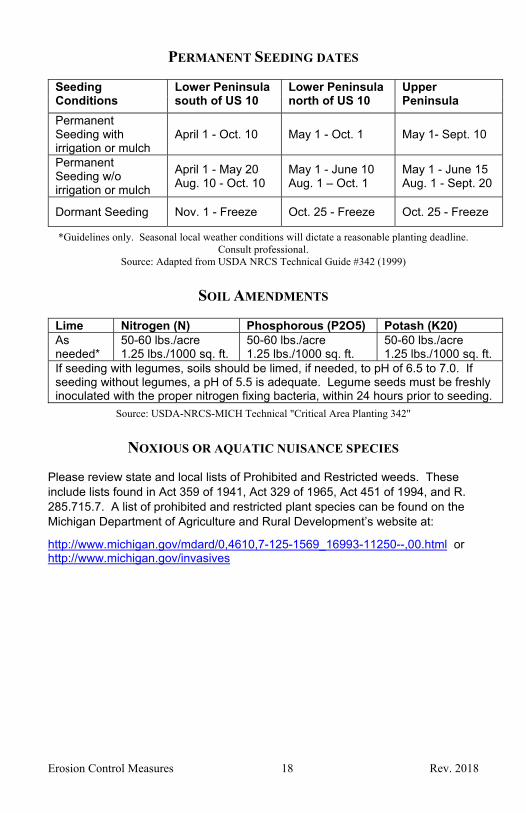
PERMANENT SEEDING DATES
Seeding Conditions
Lower Peninsula south of US 10
Lower Peninsula north of US 10
Upper Peninsula
Permanent Seeding with irrigation or mulch
April 1 - Oct. 10 May 1 - Oct. 1 May 1- Sept. 10
Permanent Seeding w/o irrigation or mulch
April 1 - May 20 Aug. 10 - Oct. 10
May 1 - June 10 Aug. 1 – Oct. 1
May 1 - June 15 Aug. 1 - Sept. 20
Dormant Seeding Nov. 1 - Freeze Oct. 25 - Freeze Oct. 25 - Freeze
*Guidelines only. Seasonal local weather conditions will dictate a reasonable planting deadline. Consult professional.
Source: Adapted from USDA NRCS Technical Guide #342 (1999)
SOIL AMENDMENTS
Lime Nitrogen (N) Phosphorous (P2O5) Potash (K20)As needed*
50-60 lbs./acre 1.25 lbs./1000 sq. ft.
50-60 lbs./acre 1.25 lbs./1000 sq. ft.
50-60 lbs./acre 1.25 lbs./1000 sq. ft.
If seeding with legumes, soils should be limed, if needed, to pH of 6.5 to 7.0. If seeding without legumes, a pH of 5.5 is adequate. Legume seeds must be freshly inoculated with the proper nitrogen fixing bacteria, within 24 hours prior to seeding.
Source: USDA-NRCS-MICH Technical "Critical Area Planting 342"
NOXIOUS OR AQUATIC NUISANCE SPECIES
Please review state and local lists of Prohibited and Restricted weeds. These include lists found in Act 359 of 1941, Act 329 of 1965, Act 451 of 1994, and R. 285.715.7. A list of prohibited and restricted plant species can be found on the Michigan Department of Agriculture and Rural Development’s website at:
http://www.michigan.gov/mdard/0,4610,7-125-1569_16993-11250--,00.html or http://www.michigan.gov/invasives

Erosion Control Measures 19 Rev. 2018
N
AT
IVE
SP
EC
IES
Erosion Control Measures 20 Rev. 2018
“Native landscaping uses only plants indigenous (or “native”) to the area. Once established, this low-maintenance form of landscaping provides habitat for many birds, butterflies and other wildlife. Thanks to their extensive, deep root system, native landscapes hold rain and survive drought much better than non-native plants and turf grass. Native landscapes are becoming more common. A popular technique is to reduce lawn sizes and use native landscaping for attractive borders. Because native plants have adapted to local soils and pests, they require less watering and need no chemicals or fertilizers to protect them. Unfertilized landscapes mean less contamination of waterways.”
Source: Heidi Natura & Conservation Research Institute

Erosion Control Measures 21 Rev. 2018
2. MULCH
When Protection against raindrop impact, runoff or wind is needed to prevent erosion or loss of seed.
Moisture retention and temperature control are required for seed germination.
Why Cost effective way to protect seeded1 and non-seeded areas and slopes against erosion from rain or wind. Holds soil moisture to allow for seed germination and reduces wind desiccation of germinated seeds. Inhibits seed consumption by birds.
Where On flat areas, drain banks, mild slopes, vegetated channel and spillway18, diversion ditch32 and dike31, and borrow and stockpile areas.
Scheduling Year around.
How 1. Install other surface runoff control measures, compact soil as required, final grade and seed1 prior to mulching.
2. Select mulch material appropriate for the site characteristics including slope, expected flow, level of traffic, installation method, accessibility and length of time protection is needed. Place loose mulch open enough to allow some sunlight and air to penetrate to the soil but thick enough to shade the ground, conserve soil moisture and prevent or reduce wind and water erosion.
3. On flat and mild slopes (flat to 4 horizontal to 1 vertical) with no concentrated flow, straw or hay may be used. Spread clean (no invasive or noxious species), dry straw or hay uniformly at a rate of 1,200 to 2,000 lbs. per acre or 28 to 46 lbs. per 1,000 square feet and anchor with a tackifier, mulch-anchoring disk, or crimping. Other organic materials may be used where acceptable rates can be established. For native plantings, only the cleanest straw mulch should be applied; hay should not be used. If hydraulic mulches are used, apply at a rate of 1,800 to 2,000 lbs. per acre.
4. On mild to average slopes (4 horizontal to 1 vertical to 3 horizontal to 1 vertical) or areas with concentrated flow apply bonded fiber matrix hydraulic mulch or single net mulch blanket. Hydraulic mulch should be applied at a rate of 2,500 to 3,000 lbs. per acre.

Erosion Control Measures 22 Rev. 2018
5. On average to steep slopes (3 horizontal to 1 vertical to 2 horizontal to 1 vertical), double net mulch blankets are effective at controlling erosion on slopes, grassed waterways and spillways18, diversion ditches32 and dikes31, borrow and stockpile areas, and flat areas and slopes during the winter.
6. On steep slopes (steeper than 2 horizontal to 1 vertical) permanent turf reinforcement mats13 should be used.
7. On grassed waterways, spillways, and diversion ditches unroll the mulch blanket across the channel and/or slope and toe or trench in 6 inches deep at the top edge of the mulch blanket. When mulch blankets must be overlapped in the direction of flow always install the downstream blanket first overlapping the upstream blanket on top a minimum of 12 inches and secure the joints with staples or stakes.
8. On flat areas and slopes, drain banks, borrow areas and stockpiles unroll the mulch blanket, linearly along the slope at roughly the same elevation, installing the lower blanket first. Toe or trench exposed edges of each blanket 6 inches deep, overlap the next layer a minimum of 6 inches and secure the joints with 6” wood pegs, staples, or stakes.
Maintenance Inspect mulched areas routinely and after each significant rainfall event to check for movement or erosion until areas are stabilized. If washouts or erosion occur, repair the surface, re-seed and re-mulch. Continue inspections as necessary until vegetation is firmly established.
Keep vehicular and pedestrian traffic and concentrated runoff away from mulched areas until they are well established.
Mulch effectively controls erosion for at least three months, but can be windblown or washed out.
Limitations Mulch can be blown or washed away if not secured. Tackifiers are slippery when wet. Equipment must be
kept clean to prevent accidents. Tackifiers can also mark vehicles, signs, or other objects if these items are not protected.
For native plantings only the cleanest straw should be applied; hay should not be used.
Mulch blankets and anchors may inhibit mowing.

Erosion Control Measures 23 Rev. 2018
Type of Mulch or Surface Coverage Materials
These are guidelines; an experienced, trained individual should review site conditions for appropriate methods and materials.
Name Typical Slope* Notes
Straw Mulch Flat to 4H:1V
Small grain straw mulch with tackifier or crimping. Apply at a rate of 1,200 to 2,000 lbs./acre.
Standard Hydro Mulch Flat to 4H:1V
Typically, 100% paper mulch with tackifier or 50% wood blend with tackifier. Apply at a rate of 1,800 to 2,000 lb./acre.
Bonded Fiber Matrix Hydro Mulch 4H:1V to 3H:1V
Apply at a rate of 2,500 to 3,000 lb./acre.
Single Net Straw Blanket 4H:1V to 3H:1V
Install with 6" wood pegs or metal staples, 36" spacing. Overlap down slope minimum 6" and bury exposed edges.
Double Net Straw Blanket 3H:1V to 2H:1V
Install with 6" wood pegs or metal staples, 24" spacing. Overlap down slope minimum 6" and bury exposed edges.
Permanent Turf Reinforcement Mat 2H:1V to 1.5H:1V
Install with 6" wood pegs or metal staples, 18" spacing. Overlap down slope minimum 6" and bury exposed edges.
*Measures may be applied to slopes steeper than shown, if applicable.

Erosion Control Measures 24 Rev. 2018
3. SODDING
When An immediate, temporary or permanent, vegetative cover is necessary or desired.
Why To prevent soil erosion. To provide immediate site restoration.
Where In residential, commercial or high traffic areas. On steep slopes, auxiliary spillways, and grassed
swales18.
Scheduling During the growing season.
How 1. Final grade, add topsoil if necessary, and scarify14 area prior to laying sod.
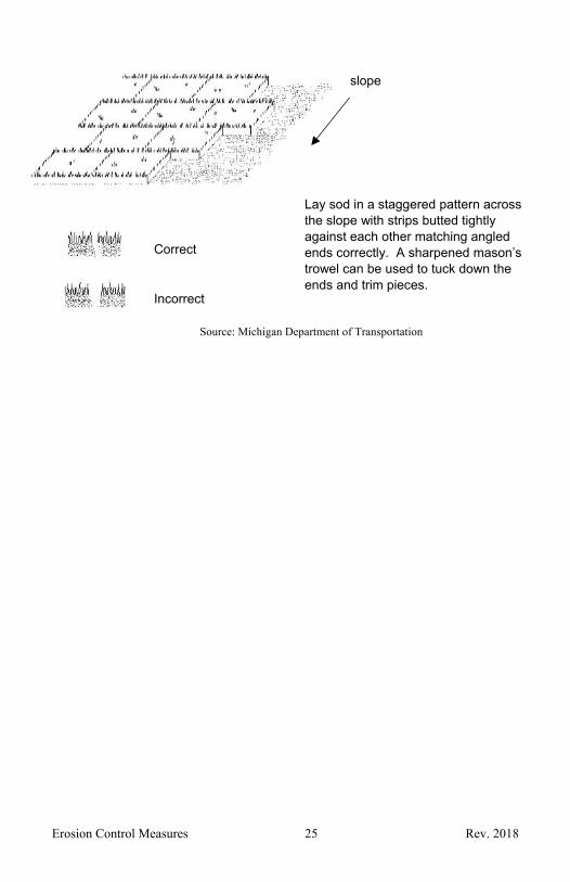
2. Lay sod in a staggered pattern across the prevailing slope, aligning angled edges so the sod lays flush.
3. On slopes steeper than 3 horizontal to 1 vertical or in concentrated flow areas, the sod shall be laid across the slope (across the direction of flow) and shall be pegged with wooden pegs, spaced not over 2 feet apart, in any direction, and shall be driven flush with the sod surface.
4. Water sod until roots have established. 5. Use sod grown on soils reasonably close to the site
soil type.
Maintenance Water regularly. Inspect weekly and following each significant
precipitation event that results in runoff for slippage and gullies, make repairs and secure as needed until well established.
Heavy maintenance equipment should not be used until the sod is established.
Limitations Requires irrigation or regular watering. Cost. Does not work well in concentrated flow areas. Shallow root structure is susceptible to slipping,
gullying and failure. Requires high maintenance to establish on steep
slopes.
Erosion Control Measures 25 Rev. 2018
Correct
Incorrect
Lay sod in a staggered pattern across the slope with strips butted tightly against each other matching angled ends correctly. A sharpened mason’s trowel can be used to tuck down the ends and trim pieces.
Source: Michigan Department of Transportation
slope

Erosion Control Measures 26 Rev. 2018
4. TREES, SHRUBS, VINES AND GROUNDCOVER
When Bare soil or recently vegetated slopes are exposed to erosive forces from wind and/or water.
Why Trees, shrubs, and some selected grasses or legumes can provide low maintenance long-term erosion protection in areas where site aesthetics are to be considered.
Enhances conditions for natural colonization of plant species from adjacent areas creating enhanced wildlife habitat.
Where In areas requiring long-term slope protection against surface erosion and shallow mass wasting or on large flat surface areas.
In wetland buffers or reservoir drawdown areas where plants may be submerged for extended periods or subject to fluctuating water levels.
Scheduling Depends on selected landscaping features.
How 1. Identify local source of native plant species suitable for collection, based on consideration of purpose, potential hydraulic limitations, climate, soil type, and moisture regime. Obtain approval for material collection.
2. Conduct slope and drain bank reshaping as required. 3. Dig plant pocket for planting according to supplier
specifications. Loosen subsoil to a depth of 4 inches. Loosen earth on sides of plant pocket to break any glazing caused by digging.
4. Install and backfill plantings according to supplier specifications.
5. Cover entire plant pocket area with 2 to 4 inches of mulch. Prune, wrap, brace, and guy as specified.
6. Stabilize all other disturbed areas.
Maintenance Inspect routinely and following each precipitation event that results in runoff until disturbed areas are stabilized.
Periodic pruning and replanting may be required to maintain healthy and vigorous vegetation.
Limitations Hand labor intensive. Costly and time intensive than seeding1. Unfamiliar to many contractors.

Erosion Control Measures 27 Rev. 2018
When vegetation matures the channel flow capacity could be reduced and may result in higher flood stages on adjacent and upstream properties.
May require irrigation during vegetation establishment.

Erosion Control Measures 28 Rev. 2018
5. PERIMETER SEDIMENT CONTROL MEASURES
(Silt Fence, Straw Wattles, Etc.)
When As a temporary measure used to capture sediment from sheet flow. May also divert small volumes of sheet flow to protected outlets.
Why The permeable barrier prevents suspended sediments from leaving the work area minimizing downstream sedimentation.
Where Between earth disturbance and drain, on drain easement boundaries and adjacent to sensitive areas, such as wetlands.
In shallow standing water to confine sediment during sediment removal.
Scheduling Year around except during frozen ground conditions.
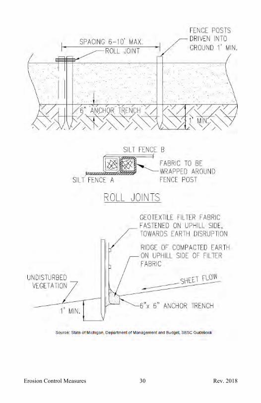
How 1. Trench in at the bottom a minimum of 6 inches, stretch and support by wooden posts on the downstream side of the silt fence. The wooden stakes should be driven to a depth of 12 inches below the ground surface and the trench should be backfilled and compacted. It may be necessary to add additional staples in the wooden posts to adequately anchor the silt fence.
2. Install along an elevation contour across the slope overlapping and rolling joints.
3. Drainage from no more than 1/2 acre should be passed through 100 feet of silt fence.
4. In areas where water ponds behind the silt fence, a stone filter berm33 may be needed to provide an outlet and prevent failure of the silt fence.
5. As an extra precautionary measure when the disturbed area is adjacent to a watercourse or on steep slopes two rows of silt fence may be necessary. They should be placed 3 feet apart and at least 3 feet from the edge of the water.
6. All excavated or surplus soils shall be removed to an upland site, disposed of outside of regulated wetlands or on an existing spoil bank and stabilized to prevent erosion in a manner that will not impair flood flows.
7. Remove silt fence after disturbed area has stabilized.
Maintenance Inspect routinely to assure it has not been knocked down and following a precipitation event that results in
Erosion Control Measures 29 Rev. 2018
runoff. Remove all sediment when it reaches 50 percent of its capacity and make repairs promptly.
Maintain until the disturbed area is completely stabilized with an effective vegetative cover.
Remove accumulated sediment and silt fence and vegetate the disturbed areas.
Limitations Labor intensive to install correctly, however improperly installed silt fence will not contain sediment and will be undercut, overtopped or will collapse.
Costly for linear projects however less expensive than removing off-site sediment.
A very limited amount of water can pass through silt fence therefore it may fail during larger storm events.
Stable outlets must be provided to prevent silt fence failure.
Silt fence is ineffective in areas of concentrated flow, such as in the drain, or directly downstream of outlets.
Measure may be less effective with silt and clay soils.
Erosion Control Measures 30 Rev. 2018

Erosion Control Measures 31 Rev. 2018

Erosion Control Measures 32 Rev. 2018
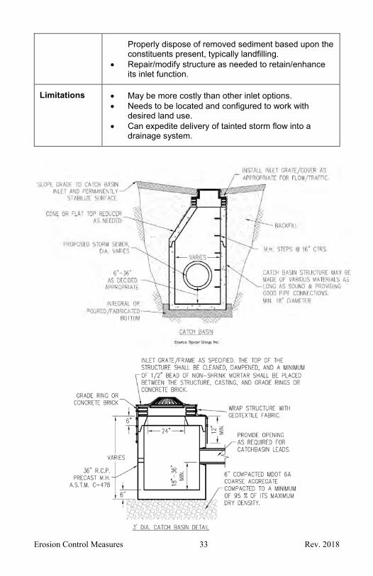
6. CATCH BASIN
When To provide a stable inlet point to a drainage system, particularly enclosed storm drain.
Why Allows preferable surface grading configuration for desired uses (streets, parking areas, yards, etc.) while providing a drainage inlet point.
Can be configured with inlet grating to limit debris and/or sediment from being carried from the inlet point into the receiving drainage system.
Can be configured with an internal sump to collect a portion of debris and sediment that makes its way into the inlet with flow.
To discourage access by wildlife/pets and/or people to drainage pipes.
Can offer added benefits of air entry & potential access/observation point to an enclosed drainage system.
Where In streets, curb lines, parking areas and/or green areas, etc.
Wherever an inlet point to a drainage system is desired for accumulated surface flow/ponding.
Scheduling Year around as long as excavation and sound backfilling can occur.
How 1. Excavate to install catch basin accommodating desired sump depth and providing for fall towards receiving drainage system. Design considerations include: basin inlet size & configuration, outlet pipe capacity, inlet and outlet elevations, pipe slope, and sump depth.
2. Backfill to grade, compacting for density. Where appropriate, place topsoil then seed1, fertilize as necessary but using low or no phosphorus mix and mulch2.
3. Install SESC measures to protect inlet. 4. Inspect routinely following each precipitation event
that results in runoff until disturbed area is stabilized. 5. Remove temporary control measures upon surface
stabilization.
Maintenance Periodically inspect basin to ensure inlet is clear, remove any debris.
Monitor and remove accumulated sediment from any sump area whenever sediment substantially fills sump.
Erosion Control Measures 33 Rev. 2018
Properly dispose of removed sediment based upon the constituents present, typically landfilling.
Repair/modify structure as needed to retain/enhance its inlet function.
Limitations May be more costly than other inlet options. Needs to be located and configured to work with
desired land use. Can expedite delivery of tainted storm flow into a
drainage system.

Erosion Control Measures 34 Rev. 2018
Source: Spicer Group, Inc.

Erosion Control Measures 35 Rev. 2018
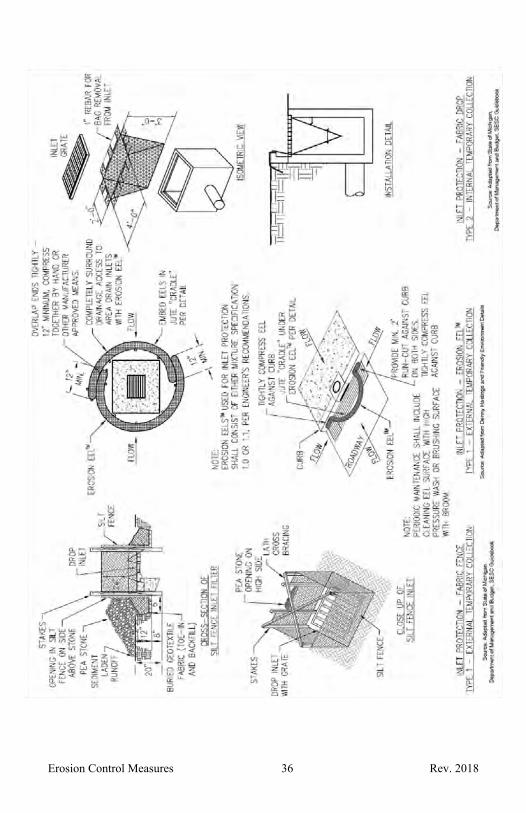
7. STORM DRAIN INLET PROTECTION
When Runoff from earth change activities will discharge to a catch basin or storm drain inlet.
A newly constructed catch basin6 or storm drain inlet needs protection until surrounding area is stabilized.
Why To prevent sediment from entering a stormwater system.
Where Around the entrance to a catch basin or storm drain inlet.
Scheduling Year around.
How 1. For catch basins and storm drain inlets in lawns; use Type 1 or Type 3 Catch Basin Inlet Filters. For catch basins in curb lines or other paved surfaces; use Type 2 or Type 3 Catch Basin Inlet Filters.
2. Provide for secondary bypass to prevent flooding during high runoff conditions.
3. Remove temporary sediment controls when project is complete and all areas are stabilized.
Maintenance Inspect routinely and following a precipitation event that results in runoff until sediment filter is removed.
Routinely remove sediment accumulation. Repair and or replace control measures as needed.
Limitations May cause temporary flooding. Plug easily and require repeated routine maintenance. Catch basin covers and silt sacks should not be used
during freezing weather because they become impermeable.
Measure may be less effective with silt and clay soils.
Type 1 External, Silt Fence5 – Filter Sock, Excelsior Log, Erosion Eels
Type 2 Internal, Temporary – Silt Sack, Inlet Pro, Catch It
Type 3 Internal, Permanent – Baffle Box, FlexStorm Pure Catch Basin Inlet Filters
Erosion Control Measures 36 Rev. 2018
Erosion Control Measures 37 Rev. 2018
8. LIVE STAKING
When Slopes or streambanks are eroding, unvegetated, or comprised of unstable soils.
Can be used for staking down surface erosion control materials.
Why To promote the re-establishment of a stable slope or streambank and potentially enhance fish and wildlife habitat.
To create a living root mat that stabilizes soil by reinforcing and binding soil particles and reduces excess moisture.
Easy to install, inexpensive method to inhibit soil movement, preserve natural drainage, and to allow native vegetation to stabilize slope.
Enhances conditions for natural colonization of plant species from adjacent areas creating enhanced wildlife habitat.
Where In areas requiring slope and bank protection against surface erosion and shallow mass wasting.
Can be installed through riprap15 to prevent soil slumping or as anchors for wattles5, straw/coir rolls, erosion control blankets13, etc.
In wetland buffers or reservoir drawdown areas where plants may be submerged for extended periods or subject to fluctuating water levels.
In areas requiring stabilization but with limited access for equipment or when little site disturbance is required.
Primarily for use in areas with soil moisture, unless additional watering is planned.
Scheduling During early spring and during the early growing season. Leaf buds should be no more than ¼ inch long when planted.
How 1. Identify local source of native plant species suitable for collection, based on consideration of purpose, potential hydraulic limitations, climate, soil type, and moisture regime. Obtain approval for material collection.
2. Conduct slope and drain bank reshaping as required. 3. Add topsoil if required, seed1. Installation of mulch2 or
an erosion control blanket13 such as straw coconut fiber mats may be necessary to stabilize live staking area. Stabilize all other disturbed areas.

Erosion Control Measures 38 Rev. 2018
4. Collect and prepare 1 to 2 inch diameter cuttings 2 to 4 feet in length from native vegetative community the same day as installation utilizing care to prevent over harvesting or depletion of native site vegetation. Keep cuttings moist. Cuttings should be taken from at least 2 year old wood. Remove side branches while leaving bark intact with buds facing upward, cut top square and bottom angled for easy installation.
5. Install live staking with a dead blow hammer a minimum of half the stake length leaving at least 2-4 inches above ground and two live buds. Be sure soil is packed firmly around the stake. Live staking is usually installed in a triangular pattern with 2 to 4 stakes per square yard and driven to a minimum depth of 2 feet.
Maintenance Inspect routinely and following each precipitation event that results in runoff until disturbed areas are stabilized.
Periodic pruning and replanting may be required to maintain healthy and vigorous vegetation.
Limitations Hand labor intensive over large areas. Unfamiliar to many contractors. Should not be planted below the ordinary high-water
mark. Not intended as a lone practice over areas of large
lateral earth pressures. May require irrigation if installed during dry seasons or
areas that naturally experience little water.

Erosion Control Measures 39 Rev. 2018
Erosion Control Measures 40 Rev. 2018
9. VEGETATION REMOVAL WITHOUT GRUBBING
When Vegetation limits flow capacity. Vegetation poses a threat to channel and bank
stability. Access is required.
Why Brushing without grubbing reduces sheet flow velocities preventing rilling and gullying, maintaining slope stability.
Trees and/or stumps located below the ordinary high-water mark may cause channel restrictions, stream bottom scour, and drain bank erosion unless removed.
Without grubbing reduces exposed soil and does not disturb the drain bottom or streambed. Roots and stumps aid bank stability.
Where In drain easements, stream or drain banks and within the channel.
Scheduling Year around; consider nesting and spawning seasons and critical habitat.
How 1. Identify areas which need to be sprayed or brushed. If possible, maintain vegetation on south and west drain banks.
2. Chemical applicators, heavy equipment, light machinery, and hand tools, may be needed.
3. Cut vegetation near the ground surface to allow for maintenance vehicle access, leave root zone intact and do not grade area. Stump treatments may be applied to prevent re-sprouting.
4. Remove cut vegetation and place within drain easement, as appropriate.
5. If a tree must be cut from within the channel, cut during low flow conditions.
Maintenance Where vegetation growth hinders flow capacity mow or chemically spray by a licensed applicator, as needed.
Limitations Stumps and other woody remnants inhibit mowing and access.
May temporarily disrupt habitat. May be restrictions in wetlands.

Erosion Control Measures 41 Rev. 2018

Erosion Control Measures 42 Rev. 2018
10. SOIL BINDING POLYMERS
When Bare soil is exposed to raindrop impact, sheet flow, rill flow or wind.
Why When used as a bare-soil spray, it provides a cost-effective alternative to reduce soil erosion and increase the infiltration rate in areas that will not be disturbed by foot or vehicular traffic.
When used as the binder for temporary or permanent seeding1, it will help control movement of seed, fertilizer, soil and amendments, during both the germination and early plant development stages. It may improve plant establishment and growth rates by increasing infiltration, reducing runoff and holding nutrients in-place for plant use.
When used in conjunction with other appropriate SESC measures, such as erosion control blankets or turf reinforcement mats13, or as part of a bonded fiber matrix, polymer binders will help minimize suspended solids in runoff.
Where Over all exposed soil surfaces or prepared seed beds prior to erosive force impact.
Scheduling Year around under bare ground conditions. The soil cannot be frozen at the time of polymer application; however, the ground can freeze after the polymer has been applied.
How 1. Users should refer to the Technical Guidance found here: http://www.michigan.gov/documents/deq/wb-stormwater-TechnicalGuidancePAMs_197048_7.pdf
2. Soil binding polymers must be applied by a knowledgeable applicator.
3. Select polymer based on bench tests which show proper chemical interaction between the subject soil and desired polymer. All polymers must be anionic polyacrylamides or anionic polyacrylamide blends in aqueous [pure] emulsion, granulated or partially hydrated form.
4. If used in granulated form over soil: spread evenly over soil surface at a rate 50lbs/acre not to exceed 100 lbs./acre. See manufacturer’s application rates.
5. If used in granulated form within compost: mix into compost and spread ½ inch thick composite so that 20-25 lbs. of polymer is used per acre.
6. If used in spray applications, add seed, mulch and other additives first, then add polymer to vigorously

Erosion Control Measures 43 Rev. 2018
agitated water so that mix ratio does not exceed 1 lb. polymer for 300 gallons water. Spray soil until the water/polymer sufficiently coats all soil particles without producing runoff.
Maintenance
Visually inspect all areas where the polymer has been applied without walking or traveling over the area following each significant precipitation or wind event and prior to expected events. Reapply if soil areas indicated disturbance by erosive forces, or if deemed necessary, reapply in conjunction with additional management practices.
Reapply if treated area is disrupted.
Limitations Polymer performance is subject to the chemical matching between the subject soil and the polymer, i.e., one polymer will not provide suitable performance for all soil types.
Concentrated flows may create erosive stress beyond the strength associated with polymeric or other spray-applied management practices.
When used alone, without seed or mulch, polymers should only be used on slopes 3 horizontal to 1 vertical, or flatter.
Limit use to areas that will not be disturbed by foot or vehicular traffic.

Erosion Control Measures 44 Rev. 2018
Seed, mulch and spray soil binding polymer applied prior to 1 inch rainfall in
October 2001.
Observed in late April 2002 without any required maintenance.
Soil binding polymer and seed being applied with hydroseeding equipment.
Source: Hanes Geo Components

Erosion Control Measures 45 Rev. 2018
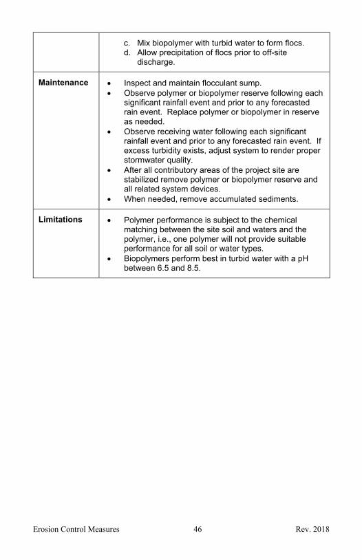
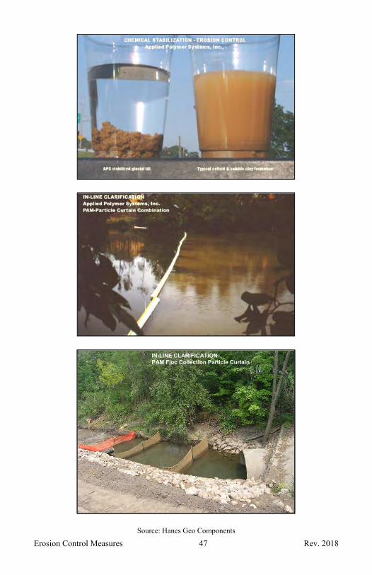
11. POLYMER OR BIOPOLYMER FLOCCULANTS
When Suspended sediments must be removed from flowing water.
Why To clarify turbid water by removing sediments and other suspended solids, reducing detrimental effects to wildlife, receiving waters, wetlands or adjacent land.
Application provides immediate effect.
Where Turbid water can be collected prior to discharging to a lake, stream, drain, or a wetland.
Scheduling Include in the planning and design phases. Prior authorization from the DEQ is required when
polyacrylamides (PAMs) or biopolymers will be used as a water additive to remove suspended particles from runoff that that will enter surface waters of the state. Go to (http://www.michigan.gov/deq/0,4561,7-135-3313_3681_3686_3728-11385--,00.html ) for information on requesting DEQ approval to use polymers. See MDEQ’s Technical Guidance for the Use of Polyacrylamides for Soil Erosion Control below.
How 1. Include polymer or biopolymer flocculants in the project planning and design phases by seeking the advice of a knowledgeable expert. Contact your local polymer supplier for additional information regarding polymers and their related application technologies.
2. When using polymers, select only anionic polyacrylamides or anionic polyacrylamide blends in aqueous emulsion, granulated or partially hydrated form. All polymers must be on both the ANSI/NSF 60 and MDEQ’s Water Treatment Additive lists.
3. Polymer selection is site-specific and can take many forms, but must incorporate all of the following: a. Select an appropriate polymer, through bench
testing, based on the site water and soil chemistries.
b. Add polymer to turbid water. c. Mix polymer with turbid water to form floc and
chelates, and d. Allow precipitation of floc and/or chelates prior to
off-site discharge. 4. Biopolymers are not soil specific and are available in
several forms. a. Select biopolymer form and determine biopolymer
quantity based on the water turbidity and quantity. b. Add biopolymer to water.
Erosion Control Measures 46 Rev. 2018
c. Mix biopolymer with turbid water to form flocs. d. Allow precipitation of flocs prior to off-site
discharge.
Maintenance Inspect and maintain flocculant sump. Observe polymer or biopolymer reserve following each
significant rainfall event and prior to any forecasted rain event. Replace polymer or biopolymer in reserve as needed.
Observe receiving water following each significant rainfall event and prior to any forecasted rain event. If excess turbidity exists, adjust system to render proper stormwater quality.
After all contributory areas of the project site are stabilized remove polymer or biopolymer reserve and all related system devices.
When needed, remove accumulated sediments.
Limitations Polymer performance is subject to the chemical matching between the site soil and waters and the polymer, i.e., one polymer will not provide suitable performance for all soil or water types.
Biopolymers perform best in turbid water with a pH between 6.5 and 8.5.
Erosion Control Measures 47 Rev. 2018
Source: Hanes Geo Components
IN-LINE CLARIFICATION PAM Floc Collection Particle Curtain
Erosion Control Measures 48 Rev. 2018
12. PLASTIC SHEETING OR GEOTEXTILE COVER
When As a temporary measure on unstable areas that are subject to erosive surface flows or severe wind.
Why To provide an immediate temporary protection of unstable areas and slopes from wind or water erosion.
Where To line a channel (i.e. temporary bypass channel35), cover stockpile areas or to provide immediate cover on exposed slopes, etc.
Scheduling Year around.
How 1. Prepare subgrade to design grade and compaction requirements.
2. Remove ruts, roots, soil clods, or other debris from the surface subject to plastic sheeting installation.
3. Consult with erosion control material supplier to select plastic sheeting based on slope gradient, expected surface runoff, and duration of use. Sheeting should be a minimum of 6 mils thick.
4. Position plastic sheets as close as possible to intended use location and unroll perpendicular to anticipated flow direction.
5. Install downstream sheets first, progressing upstream or upgradient overlapping all edges by a minimum of 18 inches. The upstream sheet must overlap the downstream sheet to prevent flow from traveling under the plastic.
6. The most upstream sheet edge must be trenched in a minimum of 18 inches.
7. Secure sheets with staples or pegs of size and length suited to soil conditions immediately after plastic sheeting is installed.
Maintenance Inspect routinely to ensure temporary plastic sheets are providing protection.
Maintain SESC measures to prevent soil from eroding onto the plastic sheeting.
Keep vehicular traffic off the plastic to prevent degradation of the plastic.
Limitations For temporary use only. Will fail if water flows beneath the plastic sheeting. Plastic is prone to damage by wind or high velocities. Will deteriorate over time.

Erosion Control Measures 49 Rev. 2018
Source: Michigan Department of Transportation
Minimum overlap 18
Silt Fence (Optional)
Plastic Sheets orGeotextile Fabric
Temporary ChannelDisturbed Soil
Minimum overlap 18 inches
Flow
Minimum overlap 18 inches
Plastic Sheets or Geotextile Fabric
Erodible Stockpile
Erosion Control Measures 50 Rev. 2018
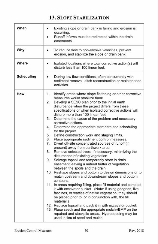
13. SLOPE STABILIZATION
When Existing slope or drain bank is failing and erosion is occurring.
Runoff inflows must be redirected within the drain easements.
Why To reduce flow to non-erosive velocities, prevent erosion, and stabilize the slope or drain bank.
Where Isolated locations where total corrective action(s) will disturb less than 100 linear feet.
Scheduling During low flow conditions, often concurrently with sediment removal, ditch reconstruction or maintenance activities.
How 1. Identify areas where slope flattening or other corrective measures would stabilize bank
2. Develop a SESC plan prior to the initial earth disturbance when the project differs from these specifications or when isolated corrective actions will disturb more than 100 linear feet.
3. Determine the cause of the problem and necessary corrective actions.
4. Determine the appropriate start date and scheduling for the project.
5. Define construction work and staging limits. 6. Place appropriate sediment control measures. 7. Divert off-site concentrated sources of runoff (if
present) away from earthwork area. 8. Remove selected trees, if necessary, minimizing the
disturbance of existing vegetation. 9. Salvage topsoil and temporarily store in drain
easement leaving a natural buffer of vegetation between the spoils and the drain.
10. Reshape slopes and bottom to design dimensions or to match upstream and downstream slopes and bottom contours.
11. In areas requiring filling, place fill material and compact it with excavator bucket. (Note: if using geogrids, live fascines, or wattles of native vegetation, they should be placed prior to, or in conjunction with, the fill material.)
12. Replace topsoil and pack it in with excavator bucket. 13. Place seed1 and the appropriate mulch2/BMP on the
repaired and stockpile areas. Hydroseeding may be used in lieu of seed and mulch.
Erosion Control Measures 51 Rev. 2018
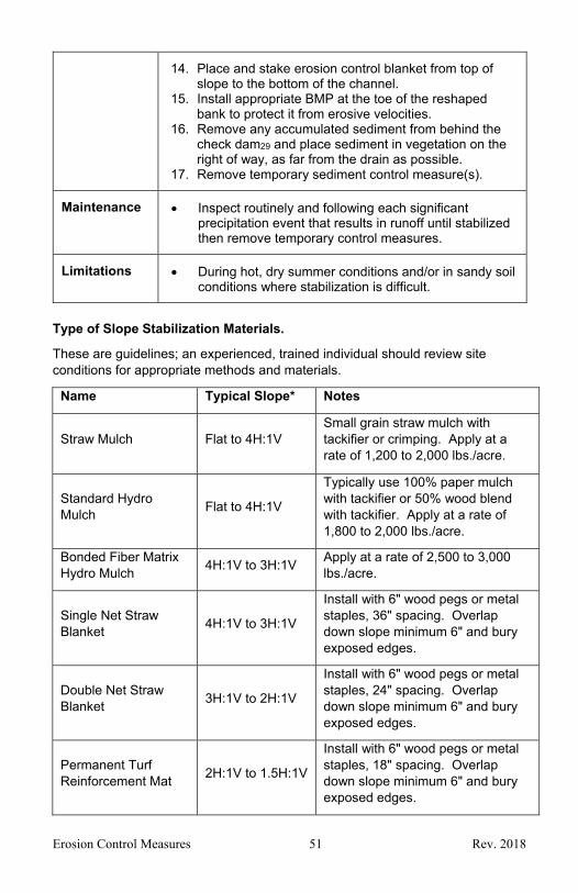
14. Place and stake erosion control blanket from top of slope to the bottom of the channel.
15. Install appropriate BMP at the toe of the reshaped bank to protect it from erosive velocities.
16. Remove any accumulated sediment from behind the check dam29 and place sediment in vegetation on the right of way, as far from the drain as possible.
17. Remove temporary sediment control measure(s).
Maintenance Inspect routinely and following each significant precipitation event that results in runoff until stabilized then remove temporary control measures.
Limitations During hot, dry summer conditions and/or in sandy soil conditions where stabilization is difficult.
Type of Slope Stabilization Materials.
These are guidelines; an experienced, trained individual should review site conditions for appropriate methods and materials.
Name Typical Slope* Notes
Straw Mulch Flat to 4H:1V Small grain straw mulch with tackifier or crimping. Apply at a rate of 1,200 to 2,000 lbs./acre.
Standard Hydro Mulch
Flat to 4H:1V
Typically use 100% paper mulch with tackifier or 50% wood blend with tackifier. Apply at a rate of 1,800 to 2,000 lbs./acre.
Bonded Fiber Matrix Hydro Mulch
4H:1V to 3H:1V Apply at a rate of 2,500 to 3,000 lbs./acre.
Single Net Straw Blanket
4H:1V to 3H:1V
Install with 6" wood pegs or metal staples, 36" spacing. Overlap down slope minimum 6" and bury exposed edges.
Double Net Straw Blanket
3H:1V to 2H:1V
Install with 6" wood pegs or metal staples, 24" spacing. Overlap down slope minimum 6" and bury exposed edges.
Permanent Turf Reinforcement Mat
2H:1V to 1.5H:1V
Install with 6" wood pegs or metal staples, 18" spacing. Overlap down slope minimum 6" and bury exposed edges.

Erosion Control Measures 52 Rev. 2018
Slope Interrupter
(Straw Wattles5, Coir Logs, etc.)
3H:1V to 1H:1V
Typically used with straw blanket or hydro mulch to mitigate down slope erosion forces and sediment collection. Tube of compost/wood chips confined with photo-degradable netting. Typically composed of 8"-12" Diameter logs, spacing down slope 10'-30' and anchored in place with 18" to 36" long wood stakes spaced 3'-5' apart.
Cellular Confinement System (Geocell)
1.5H:1V to 1H:1V
Typically installed with 24" J-Hook anchors at 20" spacing. Place 6 oz./syd. of non-woven geotextile beneath geocell and infill with stone. Textile not required when infilling with soil and seed.
*Measures may be applied to slopes steeper than shown, if applicable.

Erosion Control Measures 53 Rev. 2018
14. SLOPE ROUGHENING AND SCARIFICATION
When Site grading or construction activities result in grades that may cause increased erosive velocities or off-site sedimentation.
Why To reduce runoff velocity, increase infiltration, aid in the establishment of vegetation, reduce erosion.
Where On disturbed slopes and stream or drain banks.
Scheduling During the growing season.
How 1. Final grade, add topsoil if necessary. 2. Roughen or scarify slope to create horizontal
depressions perpendicular to the slope by running tracking machinery up and down the slope, scarifying the slope or back-blade along a slope contour.
3. Establish vegetation or cover soil to ensure its resistance to soil erosion, sliding, or other earth movement. Or place woody debris from other maintenance activities, lay a brush mat.
4. Remove temporary SESC measures when disturbed areas are stabilized.
Maintenance Inspect routinely and following each precipitation event that results in runoff and make repairs until all disturbed areas are stabilized.
Limitations Roughening and scarification has limited effectiveness on its own, but is used to speed revegetation.
Steep slopes and accessibility limit ability to use heavy equipment to roughen soil.

Erosion Control Measures 54 Rev. 2018

Erosion Control Measures 55 Rev. 2018
15. RIPRAP
When Raw, erodible areas need protection against concentrated flows that have the potential to create scour, down-cutting, or lateral cutting where vegetative measures may not be adequate.
Why To stabilize and protect stream and drain banks, maintain capacity, protect against wave attack, and reduce sediment load.
Where On steep slopes subject to weathering or seepage, for channel liners, inlet and outlet protection at culverts, drain bank protection and to protect shorelines subjected to wave action, or other areas where vegetation cannot be established.
At culvert outlets can be used to protect the stream bed and channel, thus reducing the flow velocity to a level that is non-erosive.
At the outlet of storm drains and as channel linings when flow velocities and concentrations are high and/or the channel slope is steep.
On channel banks where the direction of flow changes and to stabilize erodible slopes.
Scheduling During lower flow periods or when emergency repairs are required.
How 1. Riprap must be clean, free of extruding rebar, sized correctly based on anticipated velocities, and placed to the proper thickness.
2. Where high water velocities are anticipated (greater than 6 ft./sec.), the riprap should be designed by an engineer to ensure that the size of stone is adequate to protect the area from erosion and off-site sedimentation.
3. Over excavate area where riprap will be placed if needed. Place riprap over geotextile fabric to prevent soil from washing out from under the riprap. The ends of the geotextile fabric should be toed into the underlying soil a minimum of 12 inches and the edges should overlap at least 2 feet. Place riprap immediately after installing geotextile fabric.
4. Install riprap to full thickness in one operation. Do not dump through chutes or use any method that causes segregation of stone sizes. When placing stone, avoid dislodging or damaging underlying geotextile fabric. Tamp individual pieces until firmly bedded.

Erosion Control Measures 56 Rev. 2018
5. Place smaller, 4 inch to 6 inch stones, in voids to form a dense, uniform and well-graded mass, or as directed by the engineer or representative of the Drain Office. Some hand placement may be necessary to obtain an even distribution of stone sizes.
Maintenance If riprap has been displaced and the geotextile fabric is damaged during high flow conditions or from vandalism, remove riprap and repair geotextile fabric by adding another layer overlapping the damaged area by 2 feet and anchoring with pins spaced 3 feet apart. Replace riprap over geotextile fabric.
Inspect following each precipitation event that results in runoff and confirm effectiveness, make necessary adjustments. Expand riprap area as needed.
Limitations Cost and access. During winter, frozen ground must be excavated and
loose fill placed before the geotextile fabric and riprap are placed.
When using large concrete slabs, it is difficult to provide adequate support to prevent undermining and failure.
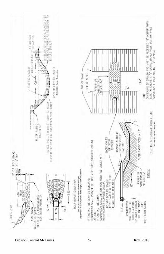
Erosion Control Measures 57 Rev. 2018

Erosion Control Measures 58 Rev. 2018
16. RIPRAP TOE OF SLOPE
When Erosion at the toe of slope is occurring. Seepage through drain bank may cause bank
sloughing or erosion.
Why To control further erosion and stabilize and protect drain banks from the erosive force of stream flow.
Where In isolated areas of bank instability with site constraints or localized erosion.
Seepage is causing slumping and slope failure at the toe of slope.
Scheduling During lower flow periods or when emergency repairs are required.
How 1. If anticipated high water velocities will exceed 6 ft./sec. utilize an engineer to properly design the toe of slope riprap protection including the required size of the stone, rock or broken concrete.
2. Install downstream sediment control measures. 3. Isolate work area from flowing water. 4. Clear and grub existing grade, as necessary for proper
installation. 5. Over excavate streambed and bank beginning at point
of proposed stream width where riprap will be placed. 6. Toe in geotextile fabric 12-18 inches below streambed
and bank. 7. Cover geotextile fabric with well graded, clean,
properly sized stone, rock, or broken concrete. If broken concrete is used, it shall not contain any protruding steel, soil or other fines, asphalt, soluble chemicals, or organic material.
8. Stabilize all disturbed areas. 9. Remove temporary SESC measures after all disturbed
areas are stabilized.
Maintenance If the riprap has been displaced and geotextile fabric is damaged during high flow conditions or from vandalism, remove riprap and repair geotextile fabric by adding another layer overlapping the damaged area by 2 feet and anchoring with pins spaced 3 feet apart. Replace riprap over geotextile fabric.
Inspect following each precipitation event that results in runoff and confirm effectiveness, make necessary adjustments. Expand riprap area as needed.
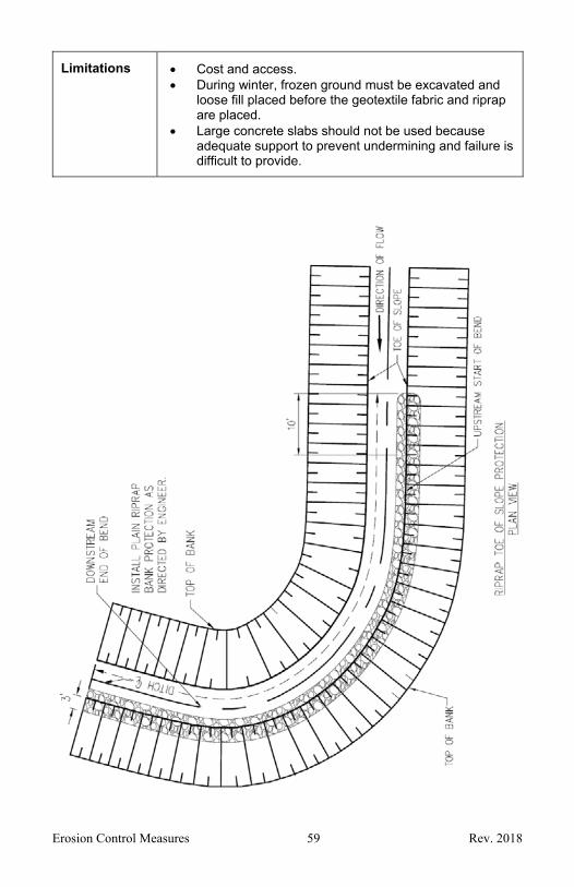
Erosion Control Measures 59 Rev. 2018
Limitations Cost and access. During winter, frozen ground must be excavated and
loose fill placed before the geotextile fabric and riprap are placed.
Large concrete slabs should not be used because adequate support to prevent undermining and failure is difficult to provide.
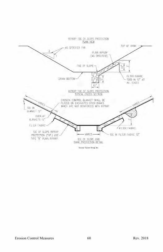
Erosion Control Measures 60 Rev. 2018
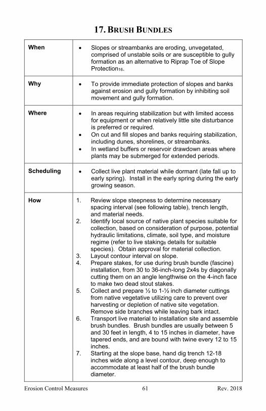
Erosion Control Measures 61 Rev. 2018
17. BRUSH BUNDLES
When Slopes or streambanks are eroding, unvegetated, comprised of unstable soils or are susceptible to gully formation as an alternative to Riprap Toe of Slope Protection16.
Why To provide immediate protection of slopes and banks against erosion and gully formation by inhibiting soil movement and gully formation.
Where In areas requiring stabilization but with limited access for equipment or when relatively little site disturbance is preferred or required.
On cut and fill slopes and banks requiring stabilization, including dunes, shorelines, or streambanks.
In wetland buffers or reservoir drawdown areas where plants may be submerged for extended periods.
Scheduling Collect live plant material while dormant (late fall up to early spring). Install in the early spring during the early growing season.
How 1. Review slope steepness to determine necessary spacing interval (see following table), trench length, and material needs.
2. Identify local source of native plant species suitable for collection, based on consideration of purpose, potential hydraulic limitations, climate, soil type, and moisture regime (refer to live staking8 details for suitable species). Obtain approval for material collection.
3. Layout contour interval on slope. 4. Prepare stakes, for use during brush bundle (fascine)
installation, from 30 to 36-inch-long 2x4s by diagonally cutting them on an angle lengthwise on the 4-inch face to make two dead stout stakes.
5. Collect and prepare ½ to 1-½ inch diameter cuttings from native vegetative utilizing care to prevent over harvesting or depletion of native site vegetation. Remove side branches while leaving bark intact.
6. Transport live material to installation site and assemble brush bundles. Brush bundles are usually between 5 and 30 feet in length, 4 to 15 inches in diameter, have tapered ends, and are bound with twine every 12 to 15 inches.
7. Starting at the slope base, hand dig trench 12-18 inches wide along a level contour, deep enough to accommodate at least half of the brush bundle diameter.

Erosion Control Measures 62 Rev. 2018
8. Place brush bundle in trench and drive dead stout stakes into slope through brush bundle every 2 to 3 feet along the entire brush bundle length.
9. Prepare live stakes that are 30 to 36 inches long by removing side branches while leaving bark intact with buds facing upward, cut top square and bottom angled for easy installation. Install live stakes, with dead blow hammer, between dead stakes on down slope side of bundles leaving live stakes protruding 2 to 3 inches above brush bundle.
10. Backfill trench with moist soil along sides of brush bundle leaving top 2 to 3 inches of brush bundle exposed. Compact soil to eliminate air pockets around buried brush bundles.
11. Move upslope to the next contour interval and repeat preceding steps.
12. Mulch2 between stakes if required to control erosion. Mulch blankets13 may be needed on slopes steeper than 3 horizontal to 1 vertical.
Maintenance Inspect routinely and following each precipitation event that results in runoff until vegetative growth has established making needed repairs promptly.
Periodic pruning and replanting of live stakes may be required to maintain healthy and vigorous vegetation.
Limitations Labor intensive.
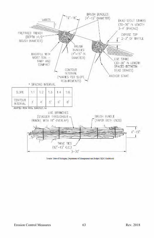
Erosion Control Measures 63 Rev. 2018
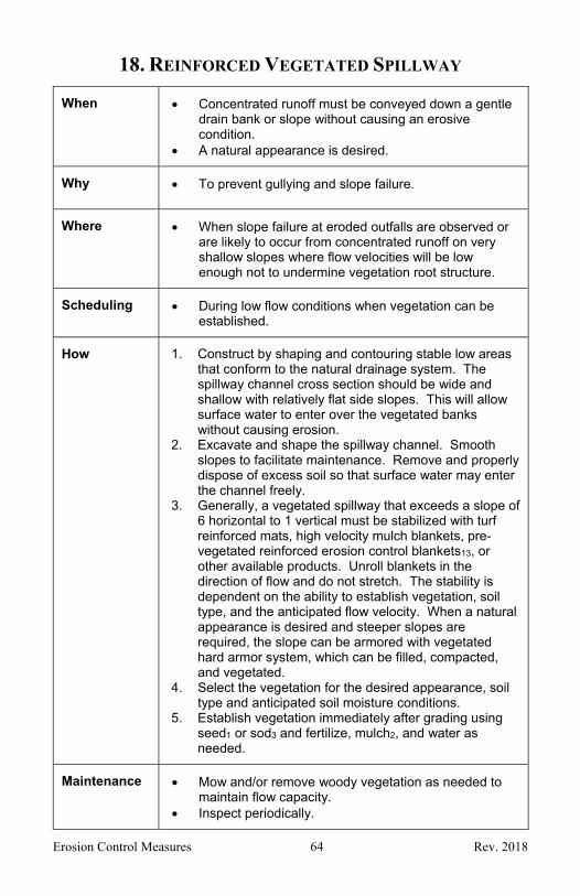
Erosion Control Measures 64 Rev. 2018
18. REINFORCED VEGETATED SPILLWAY
When Concentrated runoff must be conveyed down a gentle drain bank or slope without causing an erosive condition.
A natural appearance is desired.
Why To prevent gullying and slope failure.
Where When slope failure at eroded outfalls are observed or are likely to occur from concentrated runoff on very shallow slopes where flow velocities will be low enough not to undermine vegetation root structure.
Scheduling During low flow conditions when vegetation can be established.
How 1. Construct by shaping and contouring stable low areas that conform to the natural drainage system. The spillway channel cross section should be wide and shallow with relatively flat side slopes. This will allow surface water to enter over the vegetated banks without causing erosion.
2. Excavate and shape the spillway channel. Smooth slopes to facilitate maintenance. Remove and properly dispose of excess soil so that surface water may enter the channel freely.
3. Generally, a vegetated spillway that exceeds a slope of 6 horizontal to 1 vertical must be stabilized with turf reinforced mats, high velocity mulch blankets, pre-vegetated reinforced erosion control blankets13, or other available products. Unroll blankets in the direction of flow and do not stretch. The stability is dependent on the ability to establish vegetation, soil type, and the anticipated flow velocity. When a natural appearance is desired and steeper slopes are required, the slope can be armored with vegetated hard armor system, which can be filled, compacted, and vegetated.
4. Select the vegetation for the desired appearance, soil type and anticipated soil moisture conditions.
5. Establish vegetation immediately after grading using seed1 or sod3 and fertilize, mulch2, and water as needed.
Maintenance Mow and/or remove woody vegetation as needed to maintain flow capacity.
Inspect periodically.

Erosion Control Measures 65 Rev. 2018
Repair gullies and re-establish vegetation as needed.
Limitations Can only be used on flatter slopes with minimal flow. Soil type limits vegetation selection and slope stability. Unstable until vegetation is established therefore
timing and scheduling is critical. Must be constructed without sharp bends or steep
grades.

Erosion Control Measures 66 Rev. 2018

Erosion Control Measures 67 Rev. 2018
19. ARMORED SPILLWAY
When Concentrated flow must be conveyed down a drain bank or slope.
Why To convey concentrated surface runoff down a drain bank or slope without causing gullying, down cutting, slope failure, or channel scour.
Provides an immediate, non-erodible cover. Prevents channel scour and drain bank erosion.
Where At the outlet of enclosed tile drains when flow velocities are erosive.
Slope failure or channel scour is observed or is likely to occur, or when runoff must be redirected around work in the drain.
Scheduling During low flow conditions when vegetation can be established.
How 1. Select a location at the top of the slope where runoff can be redirected to a natural drainage swale or a location where a channel can be constructed.
2. Utilize a qualified professional for the design of an armored spillway that can handle, at a minimum, the 10-year, 24-hour storm discharge and velocity. The design includes selection of the appropriate riprap size, the spillway width and depth, and an evaluation of the hydraulic jump effects at the toe or hydraulic grade line interface to assure a stable discharge area. Material selected for riprap should be hard, angular, well graded, and resistant to weathering.
3. Install downstream sediment control measures. 4. The extent of the riprap should always start at least 2
feet above the upper edge of the geotextile fabric and end at a stabilized contour point.
5. Remove all vegetation and woody debris and shape and contour the spillway and discharge area.
6. Place riprap15 over geotextile fabric adequately anchoring all sides according to engineering drawing specifications. Add riprap to a depth of at least 12 inches and 1.5 times the maximum stone diameter, whichever is greater. Larger riprap should be uniformly distributed first followed by smaller rocks filling in the voids. Slightly overfill riprap material to allow for settling.
7. When riprap extends into moving water utilize an engineer to assure it is appropriately sized for the channel flow and the geotextile fabric is anchored at to

Erosion Control Measures 68 Rev. 2018
a minimum depth of 18 inches below the channel bottom. Isolate work area from flowing stream during installation with appropriate diversion methods.
8. Stabilize all disturbed areas. 9. Remove temporary SESC measures after all disturbed
areas are stabilized.
Maintenance Inspect immediately after the first precipitation event that results in runoff and promptly make any needed adjustments or repairs. Inspect routinely thereafter.
Limitations The riprap weight causes it to sink in unstable and mucky soils if it is not placed on geotextile fabric.
Limited to shallower slopes.

Erosion Control Measures 69 Rev. 2018
20. TOE DRAIN
When When a bank is eroding due to seepage and piping.
Why To intercept groundwater and prevent further piping and erosion.
Where Where piping is causing erosion. (Areas of “water sand”)
Scheduling During low flow periods.
How 1. Identify groundwater seepage areas that are experiencing piping.
2. Dig a trench within the drain easement away from the drain bank to a depth below the existing groundwater elevation, or deeper if specified by the engineer.
3. Line trench with non-woven geotextile fabric. 4. Add pea-stone to bottom of trench. 5. Install perforated pipe at the appropriate grade in the
trench on top of the pea-stone layer. 6. Cover pipe with pea-stone and wrap geotextile fabric
over pea-stone. 7. Install one or more pipe outlets into receiving ditch and
stabilize the ends of the outlet pipes with riprap15. 8. Fill trench with excavated soil or sand. 9. Reshape bank and stabilize all disturbed areas.
Maintenance Inspect seepage area routinely and following each precipitation event that results in runoff until disturbed areas are stabilized and seepage control is confirmed.
Limitations Cost.

Erosion Control Measures 70 Rev. 2018
21. PIPE DROP SPILLWAY
When Concentrated runoff must discharge from a higher to lower elevation within a short horizontal distance, down steep slopes, or when soils are highly erodible or excessively wet.
Why To effectively allow runoff to drop in elevation rapidly without causing an erosive condition.
Where Within a drain bank.
Scheduling During lower flow conditions, preferably when vegetation can be established.
How 1. Identify locations of concentrated flow along the top of a slope.
2. Utilize an engineer when designing a pipe drop spillway and a stable pipe outlet that can convey, at a minimum, the 10-year, 24-hour storm discharge and velocity. This includes selection of the appropriate pipe size, the pipe inlet and outlet design, and a stable outlet. Drop pipe inlets with a debris rack or a flared inlet structure with sediment sumps37 are preferred inlet alternatives. Install the pipe with a minimum slope of 3 percent. The last 4 feet of pipe should be at a 1 percent slope or less to reduce outlet velocities. (See drawing).
3. Install downstream sediment control measures. 4. Thoroughly compact soil around and under the pipe
entrance or inlet structure in multiple lifts and construct sediment sumps37 upgradient of the pipe inlet.
5. Install pipe and anti-seep watertight collars along pipe and at pipe joints.
6. Backfill around and over the pipe with a suitable soil and compact in lifts.
7. Construct a compacted earthen berm between the pipe inlet and drain.
8. Toe in non-woven geotextile fabric under the pipe outlet extending the fabric to the anticipated extent of the riprap15. When riprap extends into moving water the geotextile fabric must be keyed in to a minimum depth of 18 inches below the channel bottom. Isolate work area from channel flow during construction using appropriate measures.
9. Adequately anchor pipe outlet.

Erosion Control Measures 71 Rev. 2018
10. Provide a stable outfall23 area and an auxiliary spillway at least 6 feet away from pipe trench over natural ground.
11. Stabilize all disturbed areas. 12. Remove temporary SESC measures after all disturbed
areas are stabilized.
Maintenance Inspect routinely and following each precipitation event that results in runoff until spillway and surrounding area is stabilized. Inspect the inlet to ensure it is free of undercutting and no water is seeping past the inlet entry and the outlet is adequately anchored.
Once stabilized, inspect periodically to assure pipe inlet, anchor points, and outlet are stable and dissipation devices are functioning properly. Remove debris and accumulated sediment and make any necessary repairs.
Limitations More costly than surface or sloped spillways. Requires bank excavation.

Erosion Control Measures 72 Rev. 2018
22. SLOPED PIPE SPILLWAY
When When concentrated runoff must be conveyed down a slope from a higher elevation to a lower elevation without causing slope erosion, gullying or slope failure.
Why To effectively allow runoff to drop in elevation down a slope without causing an erosive condition.
Where Within a drain bank.
Scheduling During lower flow conditions, preferably when vegetation can be established.
How 1. Identify locations of concentrated flow along the top of a slope.
2. Utilize a qualified professional for the design of a sloped pipe spillway and a stable pipe outlet that can convey, at a minimum, the 10-year, 24-hour storm discharge and velocity. This includes selection of the appropriate pipe size, the pipe inlet and outlet design, and a stable outlet. If the inlet is a standpipe with holes, the holes should be a minimum of 2 inches in diameter and the pipe should extend vertically no more than 6 inches below the top of the dike.
3. Install downstream sediment control measures. 4. Thoroughly compact soil around and under the pipe
entrance or inlet structure in multiple lifts. If sediment accumulation is anticipated construct sediment sumps37 upgradient of the pipe inlet.
5. Install pipe and anti-seep watertight collars along pipe and at pipe joints.
6. Backfill around and over the pipe with a suitable soil and compact in lifts.
7. Construct a compacted earthen dike between the pipe inlet and the drain and stabilize all disturbed areas.
8. Toe in non-woven geotextile fabric under the pipe outlet extending the fabric to the anticipated extent of the riprap15. When riprap extends into moving water the geotextile fabric must be keyed in a depth of 18 inches below the channel bottom. Isolate work area from channel flow during construction using appropriate measures.
9. Adequately anchor pipe outlet. 10. Provide a stable outfall area23 and an emergency
spillway at least 6 feet away from pipe trench over natural ground.
11. Stabilize all disturbed areas.

Erosion Control Measures 73 Rev. 2018
12. Remove temporary SESC measures after all disturbed areas are stabilized.
Maintenance Inspect routinely and following each precipitation event that results in runoff until spillway and surrounding area are stabilized. Inspect the inlet to ensure it is free of undercutting and no water is seeping past the inlet entry and the outlet is adequately anchored.
Once stabilized, inspect after each significant runoff event to assure pipe inlet, anchor points, and outlet are stable and dissipation devices are functioning properly. Remove debris and accumulated sediment and make any necessary repairs.
Limitations More costly than surface spillways. Requires some bank excavation. Susceptible to failure if not installed properly. This
includes proper soil compaction, installation of pipe and anti-seep collars, and adequately anchoring and stabilizing the pipe outlet including energy dissipation if necessary.

Erosion Control Measures 74 Rev. 2018

Erosion Control Measures 75 Rev. 2018
23. OUTFALL STABILIZATION
When Enclosed drain enters open channel. Field tile, Sloped Pipe Spillway22 and/or Pipe Drop
Spillway21 discharges to an open channel. Existing outfall point is eroding.
Why To prevent erosion at existing or new outfall points to an open channel.
Where On an open channel bank, usually above the ordinary high-water mark.
Scheduling During lower flow periods or when emergency repairs are required.
How 1. Install downstream sediment control measures. 2. Recess pipe outlet into bank to prevent protruding. 3. Install riprap15 or other suitable stabilization material
on bank immediately below invert of outfall, underlay with non-woven geotextile fabric as may be necessary to ensure stability.
4. Where possible, direct flow downstream. 5. Install riprap and/or other suitable stabilization
material on opposite bank, if needed, to prevent erosion.
6. Construct a small berm at the top of bank above outfall to prevent gully erosion at trench.
7. Install rodent guard, as appropriate to limit access into outfall.
8. Stabilize all disturbed areas. 9. Remove temporary SESC measures after all
disturbed areas are stabilized.
Maintenance Inspect following subsequent outfall discharge event(s) for any scour/erosion at the outfall point and on opposite bank. Repair/modify and monitor until area is stabilized.
Limitations Cost. Access. Installation in frozen ground may necessitate
importing suitable fill material as stabilization material must make continuous contact with underlying soil to be effective.
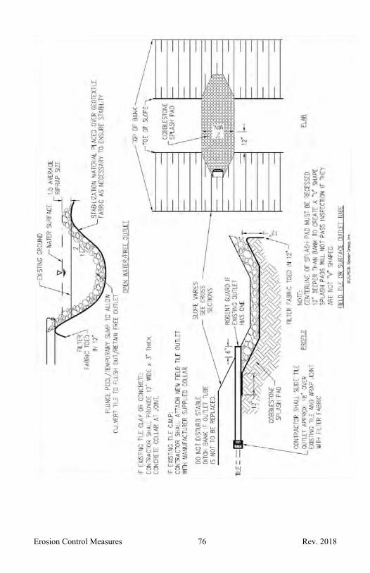
Erosion Control Measures 76 Rev. 2018

Erosion Control Measures 77 Rev. 2018
24. ENERGY DISSIPATORS
When Discharge velocity of concentrated flow exceeds the erosive velocity of the receiving area or channel.
Why To dissipate energy and reduce the discharge velocity of concentrated flow preventing erosion of the receiving area or channel.
Where At the outlets of spillways, culverts, drainage pipes, or other conduits when concentrated flow is anticipated to exceed the erosive velocity. Effective configuration of dissipator varies depending on location of it in upland or lowland/open water.
Scheduling Upon installation of a new concentrated flow outlet point.
For existing upland locations, it is preferable to work during low flow conditions or when flows are being temporarily diverted from the concentrated flow conduit.
Whenever it is observed that an existing structure is not providing suitable stability.
How 1. Identify new discharge points likely to cause scouring of the receiving area or channel or discover an existing discharge point where scouring occurs.
2. Utilize an experienced individual or an engineer to properly size and configure the necessary components to create an effective energy dissipator based on: discharge volumes, flow velocities, soil types, slope and/or water depth. Specific configuration such as deflector buckets, stilling basins, and plunge pools are effective energy dissipating devices for given situations. There are also a wide variety of pre-manufactured energy dissipators should be installed per the manufacturer’s specifications. It may be necessary to augment an energy dissipator installation in accordance with Outfall Stabilization23 when located on the bank of an open channel.
3. Install downstream sediment control measures before commencing earth change activities.
4. Stabilize all disturbed areas. 5. Remove temporary SESC measures after all disturbed
areas are stabilized.

Erosion Control Measures 78 Rev. 2018
Maintenance Inspect routinely, based on flow conditions, until all disturbed areas are stabilized.
Inspect after major flood events and remove sediment and accumulated debris and confirm dissipation device is functioning as designed, making any needed adjustments.
Limitations Cost. Access.
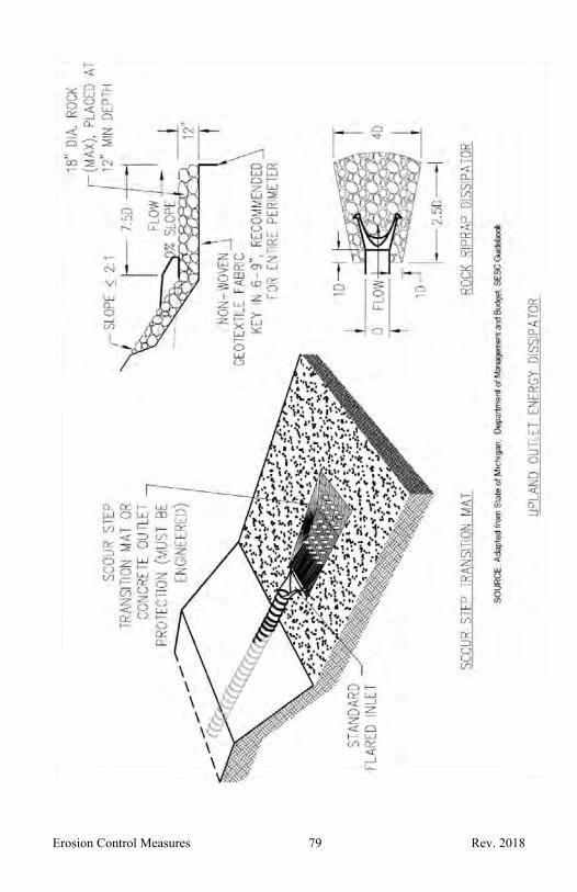
Erosion Control Measures 79 Rev. 2018

Erosion Control Measures 80 Rev. 2018

Erosion Control Measures 81 Rev. 2018
25. SAND OR STONE FILLED BAGS
When Temporarily during construction and until all disturbed areas are stabilized when areas of water require diversion or isolation.
Why To temporarily isolate an earth change activity from flowing water.
To divert water around a construction area. To impound water temporarily in a stream or drain
when flow is minimal and construction activities will be completed in a very short timeframe or when stream flow must be impounded and pumped around39 or over a crossing during construction.
Where Within or adjacent to a stream or drain. At the ends of a temporary culvert crossing. On the downgradient side of a construction area.
Scheduling Year around.
How 1. Fill burlap or woven polyethylene sand bags 2/3 to 3/4 full and stack in an alternating brick pattern to desired elevation. When used as a temporary check dam follow the check dam details29. When used to impound water that will be pumped around the construction area follow the dewatering details. When used as a temporary diversion dike31 follow the diversion dike details.
2. Complete construction and earth change activities and stabilize disturbed areas.
3. Remove any accumulated sediment from behind the bags prior to removing the sand or stone filled bags.
Maintenance Inspect bags daily during construction activities and repair as needed.
Limitations Cannot be used as a filtering device because they do not allow for an adequate movement of water through the bags.

Erosion Control Measures 82 Rev. 2018
Erosion Control Measures 83 Rev. 2018
26. DUST CONTROL
When Unprotected areas are being eroded by wind. Road surfaces tracked with soil.
Why To reduce wind erosion and the resulting off-site sedimentation. To reduce dust clouds and reduced visibility.
Where On exposed and unstabilized areas and road surfaces near construction sites.
Scheduling Year around, but most commonly during periods of low precipitation, low humidity and high temperatures. For roadways, regular street sweeping.
How 1. Dust control applications can include watering, chemical dust suppressions, gravel or asphalt surfacing, temporary aggregate cover27 and haul truck covers. Oil should not be used for dust control.
2. Minimize length of time disturbed areas are left unprotected.
3. Quickly stabilize exposed soil by vegetation, mulch2, soil erosion control blankets13, polymers10, sprinkling, or stone layering to minimize areas in need of dust control.
4. Follow manufacturer’s instructions regarding application of any dust palliative. Pay particular attention to mixing details.
5. Dust suppressants can be applied using a pressure hose attached to a distributor truck.
6. Limit vehicular traffic on unprotected areas to 15 miles per hour.
7. Regular street sweeping.
Maintenance Frequent, even daily application may be required to increase effectiveness.
Do not over water, as over watering may cause erosion.
Regular street sweeping.
Limitations Some types of dust control may reduce infiltration and result in higher runoff rates increasing the potential for erosion.
Continued effectiveness may require repeated applications.
Erosion Control Measures 84 Rev. 2018

Erosion Control Measures 85 Rev. 2018
27. STABILIZED SURFACE COVER
Wh
en
Prior to initiating or during major earth change activities when construction activities are expected to reduce or eliminate vegetative cover. The project duration and anticipated frequency of use shall be considered when determining stabilized surface cover material.
Why Minimize fugitive dust and tracking of soil throughout construction site.
Where At locations where a temporary or permanent stable condition is needed for construction operations, equipment storage, or in heavy traffic areas or any areas which could develop into a soil erosion problem as a result of intense activities and loss of vegetative cover.
Scheduling Year around.
How 1. When conducting earth change activities adjacent to public roads locate in accordance with traffic and safety guidelines.
2. Location should consider potential use as a foundation for a permanent access by the landowner or for drain maintenance.
3. Remove vegetation and other objectionable material such as trees, stumps boulders, etc. from the foundation area.
4. Place geotextile fabric beneath the aggregate to stabilize the foundation.
5. Place 2-3 inch diameter crushed rock or gravel, wood chips, or other approved material in sufficient width and length and a minimum of 3 inches deep.
6. If the stabilized surface cover slopes toward a road or off of a drain easement, or upgradient of a culvert, install silt fence5 or other perimeter control measures on one or both sides of the gravel construction exit.
7. When access is temporary, cover material and geotextile fabric must be removed and area restored and re-vegetated.
Maintenance Inspect stabilized surface cover routinely and replace or replenish stabilized surface cover materials during construction if it is no longer preventing soil erosion.

Erosion Control Measures 86 Rev. 2018
Limitations Effectiveness can be limited if not maintained or installed improperly.

Erosion Control Measures 87 Rev. 2018
28. STONE CONSTRUCTION ACCESS
When Prior to initiating major earth change activities when construction equipment is expected to transport soil onto public roads. The project duration and anticipated frequency of use shall be considered when determining if a stone construction exit is warranted.
Why Minimize fugitive dust and tracking of soil onto a roadway.
Where At locations that construction equipment will enter and exit the drain easement and tracking of soil is anticipated. Typically, in high use access areas.
Scheduling Year around.
How 1. When conducting earth change activities adjacent to public roads locate in accordance with traffic and safety guidelines.
2. Location should consider potential use as a foundation for a permanent access by the landowner or for drain maintenance.
3. Remove vegetation and other objectionable material such as trees, stumps boulders, etc. from the foundation area.
4. Install a culvert and a sediment sump37 on the downstream end of the culvert whenever stone construction exit will block surface runoff.
5. Place geotextile fabric beneath the aggregate to stabilize the foundation.
6. The stone construction exit approach should be a minimum of 50 feet long, 12 feet wide, 6-8 inches deep, and crowned for positive drainage. The aggregate should consist of 1x3 inch diameter crushed rock, gravel, ballast, or reconstituted concrete.
7. If the stone construction exit approach slopes toward a road or off of a drain easement, or upgradient of a culvert, install linear sediment sumps on one or both sides of the stone construction exit.
8. If the stone construction exit approach slopes toward a roadway or off of a drain easement, at a 2 percent grade or more, construct a ridge transversely 6 to 8 inches high approximately 15 feet from the road or drain easement boundary to divert runoff into sediment sumps on one or both sides of the stone construction exit.

Erosion Control Measures 88 Rev. 2018
9. When access is temporary, aggregate and geotextile fabric must be removed and area restored and re-vegetated.
Maintenance To prevent premature failure, large quantities of soil on equipment tires should be removed prior to driving across the stone construction exit.
Inspect stone construction access routinely and when it becomes ineffective scrape the top layer and add a 2 inch layer of aggregate.
Remove materials tracked onto roadways daily and outside of drain easement as soon as possible.
Limitations Effectiveness can be limited; sediment may be tracked onto roads requiring street sweeping.
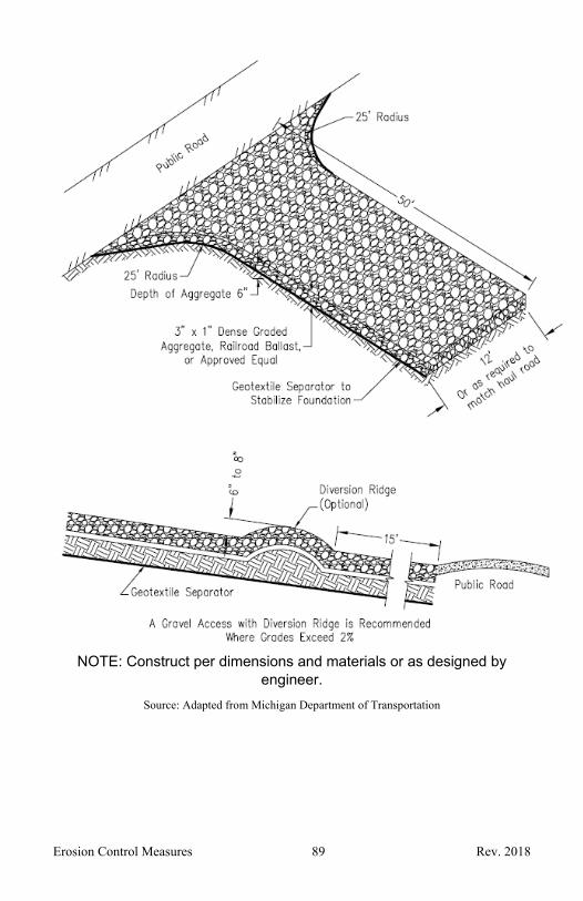
Erosion Control Measures 89 Rev. 2018
NOTE: Construct per dimensions and materials or as designed by engineer.
Source: Adapted from Michigan Department of Transportation

Erosion Control Measures 90 Rev. 2018
29. TEMPORARY CHECK DAM
When To stabilize constructed and existing flow corridors when concentrated flow is anticipated to exceed the erosive velocity. Permanent feature in upland areas to slow flow velocity and help establish vegetative growth.
Temporary feature to control sediment in a stream immediately downstream of culvert or structure work, commonly in conjunction with a sediment sump37.
Why To reduce water velocity minimizing erosion in flow corridors and channels.
To temporarily protect vegetation during early stages of growth or permanently to reduce flow velocities.
Where Within and across an existing or constructed flow corridor.
Scheduling Year around.
How 1. Configure check dams to site specific conditions. Utilize an engineer as necessary to determine the notched center dimensions and spacing between check dams based on channel slope, flow length, discharge, flow velocity, and soil type. Permanent check dams should be designed to pass, at a minimum, a 10-year, 24-hour storm at non-erosive velocity.
2. Permanent check dams should be constructed of clean rock placed on geotextile fabric which has been toed in a minimum of 3 inches. Ninety percent of the rock should range between 2 to 4 inches for slopes less than 2 percent and 3 to 12 inches for steeper grades. The rock size should be large enough to stay in place during anticipated flows. When larger rock is used, place smaller aggregate immediately upstream to filter sediment and improve efficiency.
3. Temporary check dams that will experience low flow conditions can utilize pea-stone or gravel filled bags25 instead of rock over geotextile fabric. New commercially available technologies include prefabricated check dams that are effective and sometimes reusable.
4. When not engineered but used in series, the toe of the upstream check dam should be set at the same elevation as lowest point in the top of the downstream check dam.
Erosion Control Measures 91 Rev. 2018
5. The side slopes of the check dam should be 2 horizontal to 1 vertical or flatter or equivalent to the existing streambank slopes.
6. The middle of the dam should be a minimum of 9 inches lower than the outer edges, allowing flow to go over the depression in the center as opposed to around the sides where it could erode the banks.
7. The outer edges should be keyed into adjacent banks and extend to an elevation above the anticipated flow depth to prevent washouts.
How
8. Riprap15 should be placed immediately below the check dam to help dissipate the energy of the water flowing over the dam. In areas of higher velocities, energy dissipation may be needed downstream of the check dam to prevent undercutting.
9. Temporary check dams should be constructed to handle the anticipated flow and sediment load until the site is stabilized. Aggregate filled bags25 are easier to remove than a rock check dam and the aggregate can usually be spread along the channel bottom when the check dam is removed. Aggregate meeting the gradation requirements of 6A is recommended; use nothing finer than pea-stone.
Maintenance Inspect check dams following each runoff event to ensure there is no piping under the structure or around the banks until the flow corridor has been stabilized.
Initiate identified repair needs as soon as possible following inspection.
Remove and properly dispose of sediment when it accumulates to 1/2 the check dam height. Spread sediment in an upland area and seed1 immediately.
In some instances, clogged stone must be cleaned to remain effective.
Inspect downstream structures to ensure they have not been damaged or clogged with displaced rock or stone.
After flow corridor or channel has stabilized remove accumulated sediment from behind the check dam. If check dam is temporary, remove check dam and then stabilize the area.
Limitations Check dams greater than 2 feet in depth at the center may seriously impact the flow characteristics of the flow corridor or channel and should not be used.
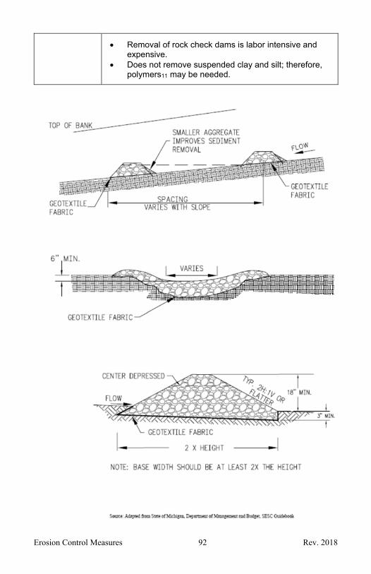
Erosion Control Measures 92 Rev. 2018
Removal of rock check dams is labor intensive and expensive.
Does not remove suspended clay and silt; therefore, polymers11 may be needed.

Erosion Control Measures 93 Rev. 2018
Source: Adapted from American Excelsior Company, Earth Science Division
Erosion Control Measures 94 Rev. 2018
30. VEGETATED BUFFER STRIPS
When Well established vegetation areas are suitably located and do not need to be disturbed to perform planned work activities.
Sufficient planning and implementation opportunity is available to establish vegetation in a suitably located buffer prior to planned work activities.
Establishment of vegetation/landscaping provides for a long term desirable use of a given area in addition to soil erosion and sediment control.
Why As a perimeter and/or random/intermittent measure to contain or partition earth disturbance activities.
Reduces sheet flow velocities preventing rilling and gullying.
Filters sediment laden runoff and reduces the potential for wind erosion.
The vegetation dissipates raindrop energy prior to reaching the soil surface and can help limit resultant runoff from its corresponding area.
Provides desired control in a more natural manner. Maintains/limits disruption to established habitat.
Where Along stream and drain corridors, sensitive areas, and shorelines.
Scheduling Assess project area for presence of ex. suitable buffers early on in project.
Then determine if identified buffer areas can be utilized for the project.
Then determine if establishment of buffer areas is appropriate for the project.
Allot sufficient time in project schedule to actually establish any new buffer.
Need to be mindful of growing season implications. Provide plans, markings and/or actual barriers in the
field as may be necessary to ensure buffer area is protected and properly utilized to serve its intended function.
How 1. Identify existing buffer areas that are available and how they can be utilized for the project. Maintain and/or enhance such buffer areas for project use as may be necessary by mowing, fertilizing, supplemental watering, etc.
Erosion Control Measures 95 Rev. 2018
2. Establish a new buffer area where desired, if none already exists, following applicable practices for stabilized vegetation establishment.
3. Provide plans, markings and/or actual barriers in the field as may be necessary to ensure buffer area is protected to serve its intended function.
4. Utilize or establish a buffer of sufficient width (typically 20 foot min.). Steep slopes, highly erodible soils and or more concentrated flows warrant use of wider buffer strips and/or supplemental measures to obtain effective function.
5. Be mindful of existing habitat and limit disruption to it as possible.
6. Be mindful to not spread invasive or weedy species and look to remove such species found to be present.
7. Utilize opportunity to encourage native and/or desirable species establishment through seed selection, overseeding, management efforts, etc.
Maintenance Monitor buffer during project duration for effective operation.
Restore markings and/or barriers defining buffer to discourage disturbance.
Remove excessive accumulated debris and sediment from buffer as appropriate and encourage established vegetation rebound/regrowth
Provide supplemental actions and/or measures to retain intended function of the buffer.
Keep any mowing to a minimum when buffer is serving as an active measure, cutting no lower than 6 inches above ground. Only mow when ready regrowth of vegetation can be expected. Be watchful for any wildlife nesting activity in area to be mowed.
Any invasive species should be removed promptly with appropriate supplemental action/measures implemented to maintain function of buffer.
Burning of a buffer strip is limited to a restorative action at a seasonally appropriate time as may be needed to encourage vegetative regrowth while such area is not needed for active control of the project or supplement measures are provided. Avoid burning during peak nesting seasons.
Limitations Lack of available width of drain easement/project area. Plowing, tilling and construction activities can damage
buffer strips. Property owner’s cooperation. Effectiveness can be seasonally dependent. Can be slow/time-consuming to establish/restore.
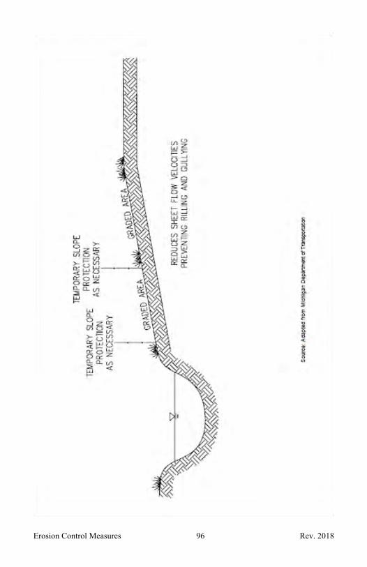
Erosion Control Measures 96 Rev. 2018
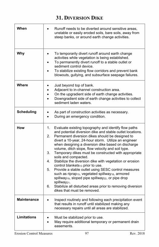
Erosion Control Measures 97 Rev. 2018
31. DIVERSION DIKE
When Runoff needs to be diverted around sensitive areas, unstable or easily eroded soils, bare soils, away from steep banks, or around earth change activities.
Why To temporarily divert runoff around earth change activities while vegetation is being established.
To permanently divert runoff to a stable outlet or sediment control device.
To stabilize existing flow corridors and prevent bank blowouts, gullying, and subsurface seepage failures.
Where Just beyond top of bank. Adjacent to in-channel construction area. On the upgradient side of earth change activities. Downgradient side of earth change activities to collect
sediment laden waters.
Scheduling As part of construction activities as necessary. During an emergency condition.
How 1. Evaluate existing topography and identify flow paths and potential diversion dike and stable outlet locations.
2. Permanent diversion dikes should be designed to divert a 10-year, 24-hour storm. Utilize an engineer when designing a diversion dike based on discharge volume, ditch slope, flow velocity and soil type.
3. Temporary dikes must be constructed with appropriate soils and compacted.
4. Stabilize the diversion dike with vegetation or erosion control blankets13 prior to use.
5. Provide a stable outlet using SESC control measures such as riprap15, vegetated spillway18, armored spillway19, sloped pipe spillway22, or pipe drop spillway21.
6. Stabilize all disturbed areas prior to removing diversion dikes that must be removed.
Maintenance Inspect routinely and following each precipitation event that results in runoff until stabilized making any necessary repairs until all areas are stabilized.
Limitations Must be stabilized prior to use. May require additional temporary or permanent drain
easements.
Erosion Control Measures 98 Rev. 2018
Source: Adapted from Michigan Department of Transportation
Erosion Control Measures 99 Rev. 2018
32. DIVERSION DITCH
When Runoff needs to be intercepted and or diverted around sensitive areas, unstable or easily eroded soils, bare soils, away from steep banks, or around earth change activities.
Why To temporarily divert runoff around earth change activities while vegetation is being established.
To permanently divert runoff to a stable outlet or sediment control device.
To stabilize existing flow corridors and prevent bank blowouts, gullying, and subsurface seepage failures.
Where Just beyond top of bank. Adjacent to in-channel construction area. On the upgradient side of earth change activities. Downgradient side of earth change activities to collect
sediment laden waters.
Scheduling As part of construction activities as necessary. During an emergency condition.
How 1. Evaluate existing topography and identify flow paths and potential diversion ditch and stable outlet locations.
2. Permanent diversion ditches should be designed to convey a 10-year, 24-hour storm at non-erosive velocity. Utilize an engineer when designing a diversion ditch based on discharge volume, ditch slope, flow velocity and soil type. Check dams29 may be necessary to reduce runoff velocity within the ditch.
3. Temporary diversion ditches can range from a shallow swale to a deeper constructed ditch.
4. Stabilize the diversion ditch with vegetation or erosion control blankets13 prior to use.
5. Provide a stable outlet using SESC control measures such as riprap15, vegetated spillway18, armored spillway19, sloped pipe spillway22, or pipe drop spillway21.
6. Stabilize all disturbed areas prior to restoring diversion ditch areas that must be removed.
Maintenance Inspect routinely and following each precipitation event that results in runoff until stabilized.
Routinely remove debris and repair ditch as needed.
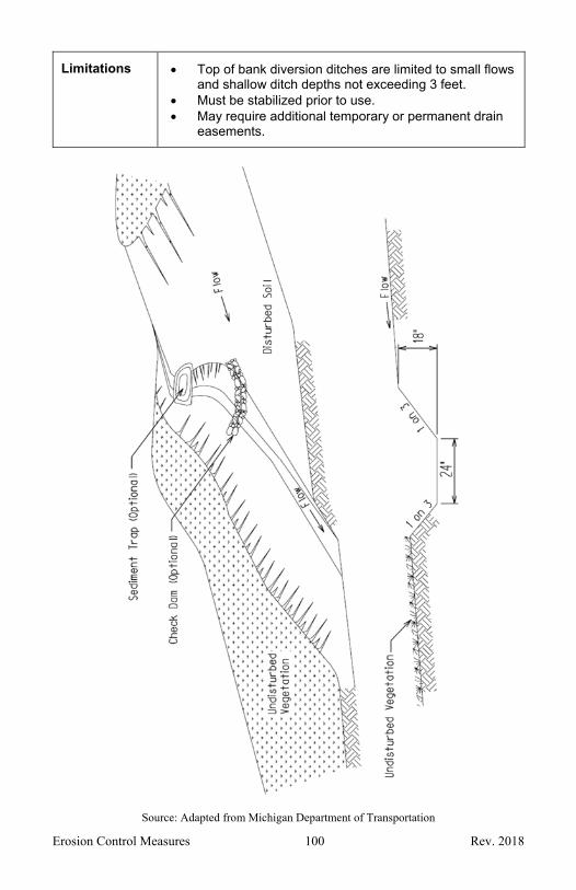
Erosion Control Measures 100 Rev. 2018
Limitations Top of bank diversion ditches are limited to small flows and shallow ditch depths not exceeding 3 feet.
Must be stabilized prior to use. May require additional temporary or permanent drain
easements.
Source: Adapted from Michigan Department of Transportation

Erosion Control Measures 101 Rev. 2018
33. STONE FILTER BERM
When Runoff from disturbed areas requires filtering before leaving a construction site.
Why To reduce the flow velocity and filter sediment from runoff.
Where In areas where sheet flow or rill flow occurs from small drainage areas.
In drainage ways where intermittent concentrated flow will not exceed 2 feet per second.
Along a site perimeter. Across construction site access roads. Around temporary spoil areas.
Scheduling Year around.
How 1. Use 3/4 to 3 inch size stone in areas of sheet flow and 3 to 5 inch stone in areas with concentrated flow.
2. Construct a sump area large enough to detain runoff volume on the upslope side of the berm where runoff can pond and sediment can settle. If drainage area is large a sediment basin36 may be needed.
3. Allow ample room to allow equipment access for sediment removal and maintenance of the berm.
Maintenance Inspect routinely and following each precipitation event that results in runoff, to assure filter berm has not plugged. Remove accumulated sediment and repair and replace gravel as needed to maintain adequate filtering and prevent berm overtopping and ultimate failure.
Limitations Should not be used in place of a check dam in a flowing ditch because they are unable to withstand velocities in excess of 2 feet per second.
Not for use in concentrated, continuous flow areas. Not for use in areas intended for mowing.
Erosion Control Measures 102 Rev. 2018
34. SAND FENCE
When In areas susceptible to wind erosion, particularly where soil has not yet been stabilized through other means.
Why To reduce wind velocities, reducing erosion. To trap blowing sand, reducing off-site sedimentation. To assist in stabilizing or re-building a slope. To minimize disturbance and identify limits of
construction.
Where Along coastal dunes, open areas subject to frequent wind, along roads, work areas, and adjacent to agricultural fields.
Scheduling Year around.
How 1. Sand fences are generally made from wooden slats spaced approximately 1.5 inches apart or consist of plastic web material.
2. Place sand fence perpendicular to the prevailing wind direction.
3. Anchor fence with sturdy posts at least 6 feet long. Drive posts into the ground approximately 2 feet.
4. Space the posts approximately 13 feet apart. Spacing may be altered to ensure posts are placed at low points.
5. Securely attach sand fence to posts on the windward side. Tying or nailing fence material to each post is often the method used.
6. The bottom of the fence must be set securely into the ground.
7. To continue effectiveness when needed, add another row of fence when the first row has accumulated sand up to 2/3 its height.
8. When sand fence is used to re-build a slope, plant vegetation to stabilize the sand when sand accumulation has slowed significantly.
9. When sand fence is used to reduce wind erosion, remove fence after disturbed areas have stabilized.
Maintenance Inspect routinely and add or maintain fence until all disturbed areas are stabilized.
Limitations Removal of fence may disturb established vegetation in stabilized areas unless adequate equipment access routes are planned.

Erosion Control Measures 103 Rev. 2018

Erosion Control Measures 104 Rev. 2018
35. TEMPORARY BYPASS CHANNEL
When Existing stream or drain must be isolated from existing or potential flow while implementing required activity.
Why To minimize downstream sedimentation and provide for an acceptable work site.
Where In, and adjacent, to a stream or drain.
Scheduling Preferably during periods of lower flow.
How 1. Design, locate, install and remove a temporary bypass channel with consideration for the topography, soils, and anticipated flow conditions and to minimize environmental disturbances. Utilize an engineer when site specific conditions warrant. Items listed below may vary based on site specific conditions.
2. Select an upland storage area near the site for excavated soil. Stabilize the stockpile and/or install silt fence5 around the stockpile area.
3. Install downstream sediment control measures. 4. Excavate a temporary bypass channel leaving earthen
plugs at each end until entire bypass channel is graded and stabilized.
5. If site conditions warrant, construct a sediment basin36 within the bypass channel just upstream of the downstream limits, leaving sufficient distance between the outlet of the sediment basin and the stream to allow placement of a check dam29.
6. Install a check dam at the downstream limits of the bypass channel.
7. Stabilize excavated stockpile. 8. Stabilize bypass channel by either; toeing in geo-textile
fabric and covering with stone to the anticipated high-water level, or line the temporary bypass channel with plastic sheets.
9. Remove downstream plug and stabilize channel from the check dam to the stream using geotextile fabric and a sturdy, non-erodible material such as riprap15 or other stream bed protection.
10. Remove the upstream plug, allowing water to pass through the temporary bypass channel.
11. Place a temporary dam made of erosive resistant material, such as: sheet piling38, sand bags25, etc., in the upstream end of existing channel to direct flow into temporary bypass channel. Following drainage of

Erosion Control Measures 105 Rev. 2018
existing steam corridor, place a temporary dam in the downstream end of the existing channel to prevent tail water from entering desired work channel. Dewater39 work area if needed.
12. When construction is complete, and all areas are stabilized, remove the temporary dam from the downstream end of the natural stream followed by the upstream temporary dam.
13. Place an earthen plug at the upstream and then the downstream ends of the temporary bypass channel stabilizing earthen plugs with riprap.
14. Backfill temporary bypass channel, dewatering if necessary.
15. Stabilize all disturbed areas. 16. When necessary, remove temporary downstream
sediment and sediment controls after all areas are stabilized.
Maintenance Inspect bypass channel, diversion berm and drain channel routinely and following each precipitation event that results in runoff until all areas are restored and stabilized.
Check downstream sediment basin for sediment accumulation. Clean out when ½ full. Place sediment on an upland site and stabilize.
Remove diversion dams when project is complete and disturbed areas have been stabilized. Restore and stabilize temporary channel and remove temporary in stream measures as needed.
Limitations Difficulties increase in proportion to size of drain. May require temporary drain easement on adjacent
riparian land. Costly to implement.

Erosion Control Measures 106 Rev. 2018
Check Dam
Check Dam
Sediment Basin
Construction Dam
Gravel Filter Berm
NOTE: Install downstream sediment control measures before commencing earth change activities.
Remove Downstream Earthen Plug and install Gravel Filter Berm when needed to control sediment
Bypass Channel
Upstream Earthen Plug
Construction Dam

Erosion Control Measures 107 Rev. 2018
36. SEDIMENT BASIN
When Earth change activities will result in sediment release. Sediment sources are from upland areas. Implementation of other soil erosion and sedimentation
control measures for are project are not anticipated to sufficiently prevent sediment discharge from a project site.
Why To provide an accessible location for sediment deposition, basin maintenance, and sediment removal.
Where In upland areas, between a drainage outlet point and project disturbance areas expected to be sediment sources.
As a component of and/or temporary application of stormwater basins.
Scheduling Year around.
How 1. Assess project area to determine if basin will be a necessary/practical control measure for expected activities and determine where it could be located.
2. Call upon an experienced individual and/or engineer to determine appropriate specifications for the basin with consideration for soil types, drainage area, desired sediment removal efficiency, and project duration from initial soil disturbance to final stabilization. Basin configurations that extend residence time by lengthening flow path, offering intermittent filtering, and/or screened outlet control typically provide improved effectiveness. Use of Polymer Flocculants11 may also be incorporated for effectiveness. Access for inspection and maintenance also needs to be considered. Include stabilized overflow point for the basin.
3. Install basin according to the specified configuration and stabilize the resulting disturbed areas prior to commencing upstream earth disturbance.
4. Monitor basin until all upstream earth disturbance has been sufficiently stabilized. Perform maintenance and/or modify configuration to enhance function as necessary.
5. Remove basin or transition to function as stormwater basin or other desired use and permanently stabilize.

Erosion Control Measures 108 Rev. 2018
Maintenance Inspect routinely, particularly following runoff events, to assess effectiveness and monitor debris and sediment accumulation.
Keep inlet and outlet fee of debris accumulation to maintain proper flow.
Repair or modify basin as appropriate for intended function.
Sediment shall be removed and the basin restored to its original dimensions when the sediment has accumulated to ½ the design depth of the basin. Removed sediment shall be deposited in the drain easement, leveled and adequately stabilized or removed to an appropriate offsite location.
Limitations Cost. Space requirement may make difficult to fit in drain
easement/project area. May become an attractive nuisance to children and
waterfowl. Configuring to ensure significant removal of fine soil
particles is challenging.

Erosion Control Measures 109 Rev. 2018
Source: Adapted from State of Michigan, Department of Management and Budget, SESC Guidebook

Erosion Control Measures 110 Rev. 2018
37. SEDIMENT SUMP (TRAP)
When Temporary sediment collection is sought within an open channel, immediately downstream of culvert and tile outlet during maintenance.
Sediment collection is sought prior to a drain inlet in upland areas.
Why To encourage and/or provide a place within open channels for accumulated sediments from within upstream enclosed drainage conduits with limited access for maintenance to flush into and then remain or be removed, if necessary.
To provide a catchment for shifting sediment to accumulate in before it can enter a drainage inlet point and be periodically removed as necessary.
Where In open channels immediately downstream of enclosed conduits.
In upland area immediately adjacent to drainage inlet points.
Scheduling Year around.
How 1. Determine if sump(s) may be applicable for expected project activities.
2. Call upon an experienced individual to determine the configuration of sump. Size and configure sump to be effective with minimal footprint. A given configuration should be able to be standardized for various applications (downstream of a culvert or tile outlet or around a catch basin) and then used routinely once determined to be effective. For open channels, a sump 50 feet long, 2 feet wide and excavated to 1 foot below final channel grade should be sufficient for a variety of applications. Sump excavation should be done such that adjacent channel banks remain stable. At drainage inlets, sump can generally be relatively small - excavated 1 foot below inlet rim/invert and a couple of feet wide around the inlet.
3. Install sump for existing drainage inlet points prior to earth change activities, otherwise install sump in association with work for a given inlet or outfall during the project as is practical.
4. A temporary Check Dam29 may be incorporated as part of the sump configuration to enhance effectiveness. Any placed check dam shall be
Erosion Control Measures 111 Rev. 2018
removed promptly upon the sump achieving its intended purpose.
5. Sump to be decommissioned once it is no longer of service by grading out and/or filling in any unwanted void and provide permanent stabilization.
Maintenance Inspect routinely, particularly following runoff events, to assess effectiveness and monitor debris and sediment accumulation.
Remove any significant accumulation of debris or sediment to maintain proper flow.
Repair or modify sump as appropriate for intended function.
Sump should generally be allowed to fill in during project such that sump area will generally return to its prior grade as the project is completed.
Limitations Is very location specific with intended minimal capacity just for that location.

Erosion Control Measures 112 Rev. 2018
Source: Adapted from State of Michigan, Department of Management and Budget, SESC Guidebook
Erosion Control Measures 113 Rev. 2018
38. SHEET PILING
When Hard armor or a retaining wall or slope protection. As a temporary cofferdam during bridge construction
or reconstruction.
Why Other options have failed or will fail under higher flow conditions or from ice damage.
To prevent seepage of contaminants into stream in rare circumstances.
To isolate work area from flowing drain.
Where In locations where a vertical/steep side slope is required.
Other permanent erosion control measures have failed.
Along or within a flowing drain or a lake.
Scheduling Year around.
How 1. Utilize an engineer when designing sheet piling, including the use of tie backs. Refer to MDOT Section 704 of the Standard Specifications for Construction for design guidance.
2. Install piling with a pile driver to the designed elevation and location.
3. Install tie backs when required to stabilize sheet piling. 4. When sheet pilling is permanent, backfill behind sheet
piling, compact fill as necessary, and stabilize disturbed areas.
5. When sheet pilling is temporary, stabilize disturbed areas after installation and restore and stabilize disturbed areas after removal.
Maintenance Inspect routinely and following each precipitation event that results in runoff until disturbed areas are stabilized then remove temporary control measures.
Inspect sheet piling annually and repair if needed.
Limitations Expensive. Natural appearance is lost. Difficult to install during frozen ground conditions. Requires Engineer review for permanent applications.
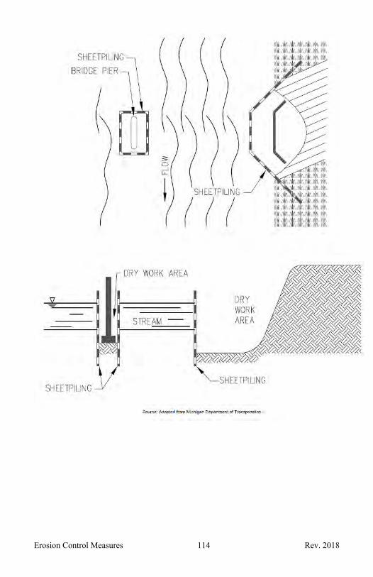
Erosion Control Measures 114 Rev. 2018

Erosion Control Measures 115 Rev. 2018
39. DEWATERING/BYPASS PUMPING
When Construction activities are limited by the presence of water and a dry work area is required.
To manage flow while working on drainage conveyances.
Maintenance activities require lower water levels. Accumulated stormwater/ponding/flooding is in need of
being eliminated.
Why To remove groundwater or surface water to facilitate construction activities.
Where A high groundwater table limits construction activities. Within or adjacent to water bodies, water courses,
drains, etc. In stormwater basins.
Scheduling Year around.
How 1. Assess specific situation to ensure dewatering/bypass pumping is the most practical means to manage water levels/flows, including determining a suitable point of discharge. Call upon an experienced individual and/or engineer to specify an adequate dewatering/bypass system to convey water quantities involved in an efficient manner and consider need and appropriate configuration for any sediment removal (filter bag placed in upland area, basin, Polymer Flocculants11) such that clear discharge results.
2. Configure dewatering system discharge point to be sufficiently stable to prevent scouring and incorporate filtering as may be appropriate.
3. Accumulated filtered sediment to be either spread and stabilized within the project limits/drain easement or properly disposed of offsite.
4. Remove all measure components promptly after needed use ceases and restore any disturbed areas.
Maintenance Maintain sediment controls and filters in good working order.

Erosion Control Measures 116 Rev. 2018
Inspect dewatering discharge points daily for signs of scour and erosion.
Repair any problems immediately.
Limitations Measure’s purpose is not treatment of contaminated water.
May require additional space/access beyond project limits/drain easement.
Freezing temperatures can present challenges.
Sou

Erosion Control Measures 117 Rev. 2018
Source: Adapted from Michigan Department of Transportation
Erosion Control Measures 118 Rev. 2018
40. TURBIDITY CURTAIN
When Slack water area is necessary to isolate construction activities from a lake or channel.
Why To provide isolation of a work area from a waterbody and contain fine grained or suspended sediments (clays and silts).
Where Parallel to flow. A re-directional barrier on the upstream end of the work area may be required to direct the stream flow away from the construction area.
Scheduling During summer or early fall when flow is low.
How 1. Install a turbidity curtain at the location shown on the plans and according to the manufacturer’s guidelines or as directed by the engineer. The curtain must be designed to handle site specific drainage or flow patterns.
2. Install a re-directional barrier on the upstream end of the work area if required.
3. Place the turbidity curtain parallel to the direction of flow. Install sufficient anchors, tie-downs, or other mechanisms to ensure proper position and performance of the curtain.
Maintenance Inspect curtain daily and make required adjustments to ensure that anchors, tie-downs, or other mechanisms are sufficiently isolating construction activities from the waterbody.
Limitations Maintenance especially during large precipitation events and within waterbodies.
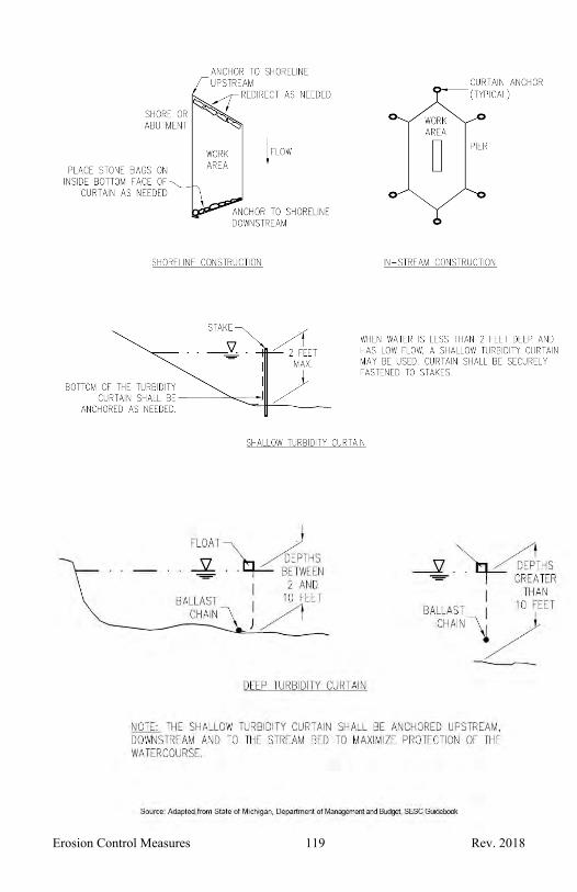
Erosion Control Measures 119 Rev. 2018

SECTION 4 – Routine Maintenance Activities

Routine Maintenance Activities 121 Rev. 2018
A. DEBRIS REMOVAL
When Deadfall, and other objects, such as shopping carts, tires, appliances, and mattresses have accumulated in the drain.
Why To prevent flooding. To prevent or remove blockages and safety hazards. To prevent bottom scour and drain bank erosion.
Where In county drains.
Scheduling Preferably during lower flow periods. Some locations require routine debris removal. During an emergency.
How 1. Remove debris minimizing channel bottom and bank disturbance.
2. When trees are uprooted and fall into a drain, cut tree off above rootball and cut tree into manageable lengths and remove from the drain. If possible reposition rootball back into its original position anchoring appropriately or remove the rootball and fill and stabilize area.
Maintenance Inspect disturbed areas routinely and following each precipitation event that results in runoff until stabilized.
Limitations Access. Cost of retrieval and disposal. Equipment availability. Safety concerns.

Routine Maintenance Activities 122 Rev. 2018
B. SEDIMENT REMOVAL
When When sediment has accumulated above the dimensions of the drain as legally established or constructed and the drain is not providing adequate drainage.
Why Remove sediment accumulation restoring proper drain function.
Where Sediment has accumulated in reaches of a drain preventing the drain from functioning as legally established or constructed.
Scheduling During low flow or frozen ground conditions. Avoid sediment removal and spreading of spoil piles
during spring thaw due to soil instability and when crops will be damaged.
How 1. Inspect drain and document eroding outfalls, obstructions, and areas of sediment accumulation. Prioritize maintenance activities and identify needed equipment. Seek engineering support when needed to analyze the drain profile in identifying reaches that need to be dredged and/or to design SESC measures taking into account the soil type, flow conditions and length of time from initial earth disturbance to project completion.
2. Develop a SESC plan prior to the initial earth disturbance when the project differs from these specifications or when removing sediment from a drain reach that exceeds 100 linear feet.
3. Prioritize and schedule maintenance, taking into account adjacent land use activities.
4. Prepare access along bank. When practical clear north and east banks to maintain shading of the stream.
5. Install downstream sediment control measures such as sediment sumps37 and check dams29 or sheet pilling38 prior to commencing earth change activities.
6. Install all other necessary SESC measures. 7. When practical, begin sediment removal downstream
and work upstream. 8. Deposit spoils along the edge of the drain easement as
far away from the drain as possible maintaining a natural buffer strip and leaving openings for natural drainage to occur. Do not place spoils in a regulated
Routine Maintenance Activities 123 Rev. 2018
wetland unless it is a historic spoil area without a wetlands permit.
9. Seed1, apply mulch2 when necessary, or otherwise stabilize disturbed drain banks daily and stabilize disturbed areas, either temporarily or permanently, within 5 days.
10. Spread spoils to prevent erosion and ditch bank surcharge and seed or otherwise stabilize spread spoils within 5 days. If spoils will be spread at a later date, seed, apply mulch when necessary, or otherwise stabilize spoil piles within 5 days except where spoil piles will interfere with plowing tilling or the harvesting of crops. If spoil piles will be left slope spoils toward agricultural fields and away from the stream or drain.
11. When removing sediment in the winter during freezing temperatures, dormant seed spoil piles daily using additional erosion control measures as required to prevent erosion.
Maintenance Inspect erosion and sediment controls routinely and following a precipitation event that results in runoff until disturbed areas are stabilized.
Limitations Cost. Access is limited by the drain easement dimensions. The cost of frequent sediment removal resulting from
unregulated sediment sources such as plowing and tilling, and urban land uses.
Additional SESC measures may be needed during the non-growing season.

Routine Maintenance Activities 124 Rev. 2018
Maintenance of a natural buffer strip between spoils and reconstructed drain prior
to drain bank stabilization.
Excavated sediment and soils being trucked off-site during a drain reconstruction project.
Source: Tuscola County Drain Commissioner
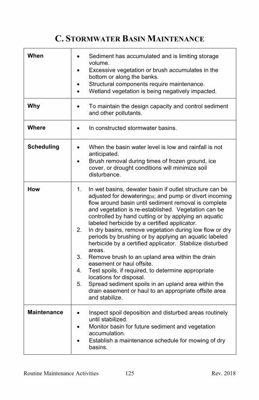
Routine Maintenance Activities 125 Rev. 2018
C. STORMWATER BASIN MAINTENANCE
When Sediment has accumulated and is limiting storage volume.
Excessive vegetation or brush accumulates in the bottom or along the banks.
Structural components require maintenance. Wetland vegetation is being negatively impacted.
Why To maintain the design capacity and control sediment and other pollutants.
Where In constructed stormwater basins.
Scheduling When the basin water level is low and rainfall is not anticipated.
Brush removal during times of frozen ground, ice cover, or drought conditions will minimize soil disturbance.
How 1. In wet basins, dewater basin if outlet structure can be adjusted for dewatering39; and pump or divert incoming flow around basin until sediment removal is complete and vegetation is re-established. Vegetation can be controlled by hand cutting or by applying an aquatic labeled herbicide by a certified applicator.
2. In dry basins, remove vegetation during low flow or dry periods by brushing or by applying an aquatic labeled herbicide by a certified applicator. Stabilize disturbed areas.
3. Remove brush to an upland area within the drain easement or haul offsite.
4. Test spoils, if required, to determine appropriate locations for disposal.
5. Spread sediment spoils in an upland area within the drain easement or haul to an appropriate offsite area and stabilize.
Maintenance Inspect spoil deposition and disturbed areas routinely until stabilized.
Monitor basin for future sediment and vegetation accumulation.
Establish a maintenance schedule for mowing of dry basins.

Routine Maintenance Activities 126 Rev. 2018
Limitations Herbicides must be applied by a certified applicator. If an herbicide is used in water it must be labeled for
aquatic use.
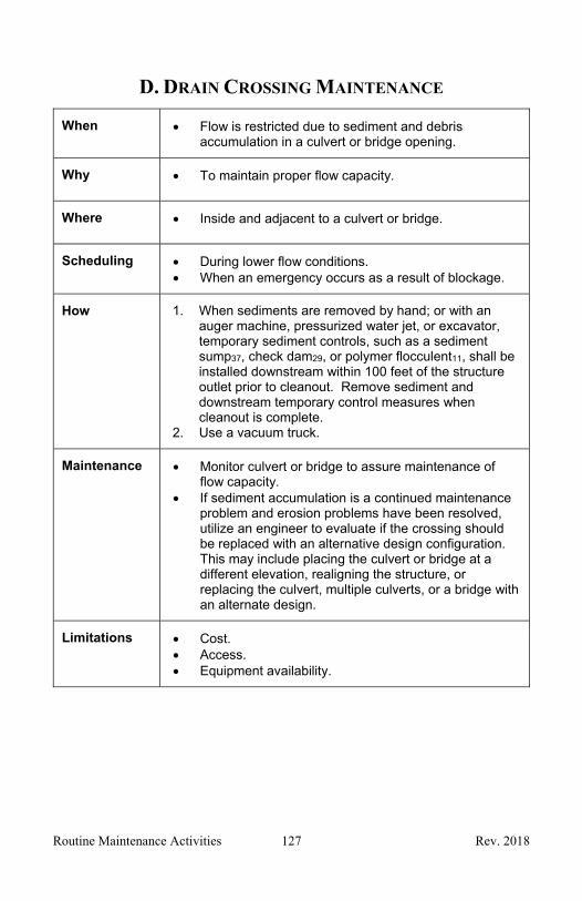
Routine Maintenance Activities 127 Rev. 2018
D. DRAIN CROSSING MAINTENANCE
When Flow is restricted due to sediment and debris accumulation in a culvert or bridge opening.
Why To maintain proper flow capacity.
Where Inside and adjacent to a culvert or bridge.
Scheduling During lower flow conditions. When an emergency occurs as a result of blockage.
How 1. When sediments are removed by hand; or with an auger machine, pressurized water jet, or excavator, temporary sediment controls, such as a sediment sump37, check dam29, or polymer flocculent11, shall be installed downstream within 100 feet of the structure outlet prior to cleanout. Remove sediment and downstream temporary control measures when cleanout is complete.
2. Use a vacuum truck.
Maintenance Monitor culvert or bridge to assure maintenance of flow capacity.
If sediment accumulation is a continued maintenance problem and erosion problems have been resolved, utilize an engineer to evaluate if the crossing should be replaced with an alternative design configuration. This may include placing the culvert or bridge at a different elevation, realigning the structure, or replacing the culvert, multiple culverts, or a bridge with an alternate design.
Limitations Cost. Access. Equipment availability.
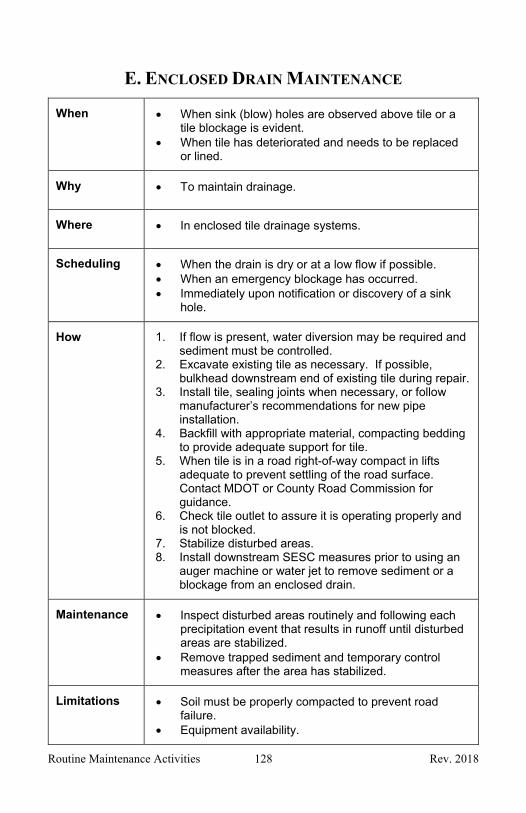
Routine Maintenance Activities 128 Rev. 2018
E. ENCLOSED DRAIN MAINTENANCE
When When sink (blow) holes are observed above tile or a tile blockage is evident.
When tile has deteriorated and needs to be replaced or lined.
Why To maintain drainage.
Where In enclosed tile drainage systems.
Scheduling When the drain is dry or at a low flow if possible. When an emergency blockage has occurred. Immediately upon notification or discovery of a sink
hole.
How 1. If flow is present, water diversion may be required and sediment must be controlled.
2. Excavate existing tile as necessary. If possible, bulkhead downstream end of existing tile during repair.
3. Install tile, sealing joints when necessary, or follow manufacturer’s recommendations for new pipe installation.
4. Backfill with appropriate material, compacting bedding to provide adequate support for tile.
5. When tile is in a road right-of-way compact in lifts adequate to prevent settling of the road surface. Contact MDOT or County Road Commission for guidance.
6. Check tile outlet to assure it is operating properly and is not blocked.
7. Stabilize disturbed areas. 8. Install downstream SESC measures prior to using an
auger machine or water jet to remove sediment or a blockage from an enclosed drain.
Maintenance Inspect disturbed areas routinely and following each precipitation event that results in runoff until disturbed areas are stabilized.
Remove trapped sediment and temporary control measures after the area has stabilized.
Limitations Soil must be properly compacted to prevent road failure.
Equipment availability.

Routine Maintenance Activities 129 Rev. 2018
Flow conditions. Cost.

SECTION 5 – Part 91 and Administrative Rules

Part 91 and Administrative Rules 131 Rev. 2018
Please go the following websites to print the most current version of Part 91 and the Administrative Rules:
PART 91, Soil Erosion and Sedimentation Control, of the Natural Resources and Environmental Protection Act, 1994 PA 451, as amended.
http://www.legislature.mi.gov/documents/mcl/pdf/mcl-451-1994-II-2-SOIL-CONSERVATION-EROSION-AND-SEDIMENTATION-CONTROL-91.pdf
ADMINISTRATIVE RULES, R 323.1701 et seq. of the Michigan Administrative Code.
http://dmbinternet.state.mi.us/DMB/ORRDocs/AdminCode/1645_2016-037EQ_AdminCode.pdf
For additional information, visit the DEQ Soil Erosion and Sedimentation Control Program Website at: www.michigan.gov/soilerosion

Part 91 and Administrative Rules 132 Rev. 2018

SECTION 6 – Glossary

Glossary 134 Rev. 2018
GLOSSARY
Accelerated Soil Erosion means the increased loss of the land surface that occurs as a result of human activities.
Authorized Public Agency (APA) means a state agency or an agency of a local unit of government authorized by the MDEQ under Section 9110 of Part 91 to implement soil erosion and sedimentation control procedures with regard to earth changes undertaken by it.
Backwater means the increased depth of water upstream of a restriction or obstruction, such as a dam, bridge or culvert.
Base Flow means the portion of stream flow that is not due to runoff from precipitation, usually supported by water seepage from natural storage areas such as groundwater, a waterbody or wetlands.
Best Management Practice (BMP) means a practice or method that’s understood to be effective and practical in achieving an objective (such as preventing or minimizing erosion, pollution, maximizing sediment collection, etc.).
Bulkhead means a plug installed in a sewer pipe constructed of concrete, brick, or masonry to block to prevent flow into or out of a conveyance system.
Certified Storm Water Operator (CSWO) means a person who has a valid Storm Water Operator for Construction Sites Certification from the MDEQ.
County Enforcing Agency (CEA) means the county agency, designated by the County Board of Commissioners under Section 9105 of Part 91 that is responsible for administration and enforcement of Part 91 and the Rules.
Cubic Yard (CYD) means a unit of volume, 1 cubic yard is equal to 27 cubic feet.
Discharge means the volume of water passing a point in a given time and is often expressed as cubic feet per second.

Glossary 135 Rev. 2018
Earth Change means a human-made change in the natural cover or topography of land, including cut and fill activities, which may result in or contribute to soil erosion or sedimentation of the Waters of the State. Earth change does not include the practice of plowing and tilling soil for the purpose of crop production.
Earth Change Permit or Permit means an earth change permit issued by a County Enforcing Agency or a Municipal Enforcing Agency authorizing work to be performed under the provisions of Part 91, the Rules, or a local SESC ordinance.
Engineer means a person, firm or corporation providing professional engineering design expertise to the County Drain Commissioner.
Forebay means a small, separate storage area near the inlet to a stormwater or sediment basin, used to trap and settle incoming sediments before they enter the basin.
Geotextile Fabric means non-woven geotextile filter fabric.
Grading means any leveling, stripping, excavating, filling, stockpiling or any combination thereof and shall include the land in its excavated or filled condition.
Grubbing means the removal of tree stumps and roots from below ground.
# Horizontal to # Vertical (#H:#V) means a measure of longitudinal or side slope, for example xH:yV means for every x feet of distance (horizontal), there is y feet of elevation change (vertical).
Lake as defined by Part 91, Soil Erosion and Sedimentation Control, of the NREPA, means the Great Lakes and all natural and artificial inland lakes or impounds that have definite banks, a bed, visible evidence of continued occurrence of water, and a surface area of water that is equal to, or greater than 1 acre. Lake does not include sediment basins and basins constructed for the sole purpose of storm water retention, cooling water, or treating polluted water. (Please note, definition differs from NREPA Part 301)
Landowner means a person who fulfills 1 or more of the following requirements:
I. The person owns or holds a recorded easement on the property.

Glossary 136 Rev. 2018
II. The person is engaged in construction in a public right-of-way in accordance with sections 13, 14, 15, and 16 of 1925 PA 368, MCL 247.183, 247.184, 247.185, and 247.186.
III. The person is engaged in a project that meets all of the following conditions: a. The project is related to 1 or more roads, highways, sidewalks,
trails, driveways, parking areas, forms of public transit, forms of nonmotorized transportation, or boating, including all structures, improvements, features, and lands related to the project.
b. One or more state agency or local unit of government owns, exercises jurisdiction over, or holds a recorded easement on the property in the area where the earth change will occur.
c. All state agencies or local units of government that own, exercises jurisdiction over, or have a recorded easement on the property in the area where the earth change will occur grant a permit or written authorization to the person that specifies where the earth change is allowed to occur.
d. No state agency or local unit of government that owns, exercises jurisdiction over, or holds a recorded easement in the area where the earth change will occur has control over the project during construction. The control prohibited by this subparagraph includes, but is not limited to, paying for or having a financial interest in the project during construction or directing contractors and other individuals engaged in construction work. The control prohibited by this subparagraph does not consist solely of establishing construction requirements or conducting inspections.
Linear Feet (LFT) means a unit of measurement.
Live Stake means a stake made from acceptable species; live, rootable, vegetative cuttings inserted into the ground.
Michigan Department of Transportation (MDOT) is a state department with jurisdiction over designated highways and interstates within the state of Michigan (e.g. I-routes, M-routes, and US-routes)
Michigan Department of Environmental Quality (MDEQ) is a state department which promotes the wise management of air, land, and water resources in the State of Michigan. This is the primary permitting agency for soil erosion and projects impacting inland lakes and streams, and wetlands.

Glossary 137 Rev. 2018
Municipal Enforcing Agency (MEA) means an agency designated by a municipality under Section 9106 of Part 91 to enforce a Local Ordinance that has been approved by the MDEQ.
Municipality means any of the following:
a. A city.
b. A village.
c. A charter township.
d. A general law township that is located in a county with a population of 200,000 or more.
National Pollutant Discharge Elimination System (NPDES) is a permitting system for regulating sources of pollution.
Natural Resource and Environmental Protection Act (NREPA) are the laws in the State of Michigan regarding many different aspects of the environment. Part 91 of NREPA regards soil erosion and sedimentation control.
Non-erosive Velocity means a speed of water movement that is not conducive to the development of accelerated soil erosion.
Notice of Coverage (NOC) is a required notice that is submitted to the MDEQ for projects disturbing more than 5 acres.
Ordinary High-Water Mark (OHWM) means the line between upland and bottomland that persists through successive changes in water levels, below which the presence and action of the water is so common or recurrent that the character of the land is marked distinctly from the upland and is apparent in the soil itself, the configuration of the surface of the soil, and the vegetation. On an inland lake that has a level established by law, it means the established high (summer) level. Where water returns to its natural level as the result of the permanent removal or abandonment of a dam, it means the natural ordinary high-water mark.
Part 91 means Part 91, Soil Erosion and Sedimentation Control, of the Michigan Natural Resources and Environmental Protection Act, 1994 PA 451, as amended, being 324.9101 et seq. of the Michigan Compiled Laws.
Glossary 138 Rev. 2018
Permanent Soil Erosion and Sedimentation Control Measures means those control measures, which are installed or constructed to control soil erosion and sedimentation and which are maintained after project completion.
Piping is when seepage is transporting soil.
Plunge pool means a deep pool into which water falls that is provided for energy dissipation.
Point bars means ridges of deposited material located in the streambed.
Rules means the Administrative Rule R 323.1701 et seq. of the Michigan Administrative Code promulgated pursuant to sections 9104 and 9114 of 1994 PA 451, MCL 324.9104 and 324.9114 of the Michigan Compiled Laws for the administration of Part 91.
Runoff means the excess portion of precipitation that does not infiltrate into the ground, but runs off and reaches a stream, waterbody, or storm sewer.
Sediment means solid particulate matter, including both mineral and organic matter that is in suspension in water, is being transported, or has been removed from its site of origin by the actions of wind, water, or gravity and has been deposited elsewhere.
Sheet Flow means runoff which flows over the ground surface as a thin, even layer, and not concentrated in a channel.
Site means the location at which the work is to be performed.
Soil Erosion means the wearing away of land by the action of wind, water, or gravity; or a combination of wind, water, or gravity.
Soil Erosion and Sedimentation Control (SESC) is an approach to prevent the erosion of soil and when that is not possible, control the erosion and the transport, or sedimentation, of soil away from a site.

Glossary 139 Rev. 2018
Stabilization means the establishment of vegetation or the proper placement, grading, or covering of soil to ensure its resistance to soil erosion, sliding, or other earth movement.
State Agency means a principal state department or a state public university.
Stilling Basin means a short length of paved channel generally placed at the foot of a spillway to dissipate energy before the flow reaches the exposed and unpaved riverbed downstream.
Stream as defined by Part 91, Soil Erosion and Sedimentation Control, of the NREPA, means a river, creek, or other surface watercourse which may or may not be serving as a drain as defined in The Drain Code of 1956, 1956 PA 40, as amended, being 280.1 et seq. of the Michigan Compiled Laws, and which has definite banks, a bed, and visible evidence of the continued flow or continued occurrence of water, including the connecting waters of the Great Lakes. (Please note, definition differs from NREPA Part 301)
Swale means a natural depression or wide shallow ditch used to temporarily or permanently convey, store, or filter runoff.
Tailwater means the depth or elevation of water at the downstream end of a structure, such as a bridge, culvert or dam.
Temporary Soil Erosion and Sedimentation Control Measures means interim control measures which are installed or constructed to control soil erosion and sedimentation and which are not maintained after project completion.
Violation means a violation of Part 91, or the Administrative Rules for Part 91.
Waters of the State means the Great Lakes and their connecting waters, inland lakes and streams, as defined in the Rules, and wetlands regulated under Part 303, Wetlands Protection, of the Natural Resources and Environmental Protection Act, 1994 PA 451, being 324.30301 et seq. of the Michigan Compiled Laws.