PROJET DE COMITÉ POUR VOTE (CDV)Project number 61204-7 Ed. 1Numéro de projet
IEC/TC or SC: SC 22ECEI/CE ou SC:
Date of circulationDate de diffusion2002-11-29
Closing date for voting (Voting mandatory for P-members)Date de clôture du vote (Vote obligatoire pour les membres (P))2003-05-02
Titre du CE/SC: ALIMENTATIONS STABILISEES TC/SC Title: STABILIZED POWER SUPPLIES
Secretary: H.Dick van ZuylenSecrétaire:Also of interest to the following committeesIntéresse également les comités suivantsTC44, TC57, TC62, SC62A, SC62B, SC62C, SC62DTC65, SC65B, SC65D, TC66, TC85, TC79, TC96TC100, TC103, TC108
Supersedes documentRemplace le document22E/74/NP & 22E/86/RVN
CE DOCUMENT EST TOUJOURS A L'ETUDE ET SUSCEPTIBLE DE MODIFICATION.IL NE PEUT SERVIR DE REFERENCE.
LES RECIPIENDAIRES DU PRESENT DOCUMENT SONT INVITES A PRESENTER,AVEC LEURS OBSERVATIONS, LA NOTIFICATION DES DROITS DE PROPRIETEDONT ILS AURAIENT EVENTUELLEMENT CONNAISSANCE ET A FOURNIR UNEDOCUMENTATION EXPLICATIVE.
THIS DOCUMENT IS STILL UNDER STUDY AND SUBJECT TO CHANGE. ITSHOULD NOT BE USED FOR REFERENCE PURPOSES.
RECIPIENTS OF THIS DOCUMENT ARE INVITED TO SUBMIT, WITH THEIRCOMMENTS, NOTIFICATION OF ANY RELEVANT PATENT RIGHTS OF WHICHTHEY ARE AWARE AND TO PROVIDE SUPPORTING DOCUMENTATION.
Titre Title:
LOW VOLTAGE POWER SUPPLIES, D.C.OUTPUT – Part 7: Safety Requirements
Note d'introduction Introductory noteThis document has the status of a draft productstandard for Safety.It has been prepared by 22E/WG2. It takes intoaccount the comments by National committeesreceived with document 22E/86/RVNThese comments were treated by 22E/WG2, inaccordance with the decisions taken at themeeting of SC22E in February 2001 in London(BSI) UK (22E/85/RM, clause X b)It is circulated at the same time as 22E/87/NP
ATTENTION
CDV soumis en parallèle au vote (CEI)et à l’enquête (CENELEC)
0 Principles of safety .......................................................................................................... 71 General ........................................................................................................................... 5
1.1 Scope ..................................................................................................................... 51.2 Definitions .............................................................................................................. 61.3 General requirements ............................................................................................. 71.4 General conditions for tests .................................................................................... 71.5 Components ........................................................................................................... 81.6 Power interface ...................................................................................................... 91.7 Marking and instructions ......................................................................................... 9
2 Protection from hazards ..................................................................................................102.1 Protection from electric shock and energy hazards ................................................102.2 SELV circuits .........................................................................................................102.3 TNV circuits ...........................................................................................................102.4 Limited current circuits...........................................................................................112.5 Limited power sources ...........................................................................................112.6 Provisions for earthing and bonding.......................................................................112.7 Overcurrent and earth fault protection in primary circuits .......................................112.8 Safety interlocks ....................................................................................................112.9 Electrical insulation................................................................................................112.10 Clearances, creepage distances and distances through insulation .........................11
3 Wiring, connections and supply.......................................................................................114 Physical requirements.....................................................................................................125 Electrical requirements and simulated abnormal conditions ............................................12
5.1 Touch current and protective conductor current .....................................................125.2 Electric strength.....................................................................................................125.3 Abnormal operating and fault conditions ................................................................12
6 Connection to telecommunication networks.....................................................................137 Connection to a cable distribution system .......................................................................13Annex PS-A (normative) Requirements for power supply units for use in Electrical
Equipment for Measurement, Control and Laboratory use ...............................................14Annex PS-B (Normative) Requirements for power supply units for use in medical
electrical equipment........................................................................................................62Annex PS-C ..........................................................................................................................63Annex PS-D (Normative) Requirements for power supply units used in audio, video
and similar household apparatus ....................................................................................64Annex PS-D.B (Normative) Apparatus to be connected to the telecommunication
networks .......................................................................................................................130Annex PS-D.G (Normative) Flammability test methods .......................................................132Annex PS-D.N (Informative) Routine tests..........................................................................135Annex PS-E (Normative) DC Power and Distribution Equipment.........................................138ANNEX PS-F (Informative) Guidance on marking and installation instructions for
proper selection of power supplies for use in information technology equipment. ..........155
INTERNATIONAL ELECTROTECHNICAL COMMISSION____________
LOW VOLTAGE POWER SUPPLIES, DC OUTPUT –
Part 7: Safety Requirements
FOREWORD1) The IEC (International Electrotechnical Commission) is a worldwide organization for standardization
comprising all national electrotechnical committees (IEC National Committees). The object of theIEC is to promote international co-operation on all questions concerning standardization in theelectrical and electronic fields. To this end and in addition to other activities, the IEC publishesInternational Standards. Their preparation is entrusted to technical committees; any IEC NationalCommittee interested in the subject dealt with may participate in this preparatory work.International, governmental and non-governmental organizations liaising with the IEC alsoparticipate in this preparation. The IEC collaborates closely with the International Organization forStandardization (ISO) in accordance with conditions determined by agreement between the twoorganizations.
2) The formal decisions or agreements of the IEC on technical matters express, as nearly as possible,an international consensus of opinion on the relevant subjects since each technical committee hasrepresentation from all interested National Committees.
3) The documents produced have the form of recommendations for international use and are publishedin the form of standards, technical reports or guides and they are accepted by the NationalCommittees in that sense.
4) In order to promote international unification, IEC National Committees undertake to apply IECInternational Standards transparently to the maximum extent possible in their national and regionalstandards. Any divergence between the IEC Standard and the corresponding national or regionalstandard shall be clearly indicated in the latter.
5) The IEC provides no marking procedure to indicate its approval and cannot be rendered responsiblefor any equipment declared to be in conformity with one of its standards.
6) Attention is drawn to the possibility that some of the elements of this International Standard may bethe subject of patent rights. The IEC shall not be held responsible for identifying any or all suchpatent rights.
International Standard IEC 61204-7 has been prepared by subcommittee 22E: Stabilizedpower supplies , of IEC technical committee 22: Power electronic systems & equipment.
IEC 61204-7 has the status of a product standard.
The text of this standard is based on the following documents:
FDIS Report on voting
22E/XX/FDIS 22E/XX/RVD
Full information on the voting for the approval of this standard can be found in the report onvoting indicated in the above table.
The committee has decided that this publication remains valid until 3 years from thepublication date. At this date, in accordance with the committees decision, the publication willbe :
Annexes A, B, C, D, E, F, G, J, K, M, N, P, U, V, Y, PS-A, PS-B (under consideration), PS-C(reserved for future use), PS-D and PS-E form an integral part of this standard.
Annexes Q, R, S, T, W, X and PS-F are for information only.
IEC 61204 consists of the following parts, under the general title: Low voltage power supplies,DC output
Part 1: Terms and definitionsPart 2: Performance characteristicsPart 3: Electromagnetic compatibility (EMC)Part 4: Tests other than EMCPart 5: Measurement of the magnetic component of the reactive near field.Part 6: Requirements for low-voltage power supplies of assessed performancePart 7: Safety RequirementsNOTE Some parts may not yet be available.
This standard IEC 61204-7 makes reference to the standard IEC60950 Edition 3 orIEC 60950-1 Edition 1 in the form of clause number/RD. In this context, RD meansReference Document i.e. IEC60950 Edition 3 or IEC 60950-1 Edition 1. Wherever the wordequipment occurs in this reference document, this means POWER SUPPLY.
In this standard, the following print types are used:
Requirements proper and normative annexes: in roman type. Compliance statements and test specifications: in italic type. Notes and other informative matter: in smaller roman type.
Normative conditions within tables: in smaller roman type.
This part of IEC 61204 specifies the safety requirements for POWER SUPPLY units (PSUs)providing DC output(s) with or without auxiliary AC output(s) operating from AC or DC sourcevoltages up to 600 V a.c. or 1 000 V d.c. (See exceptions in 1.1.3).
NOTE Ringing Generators used in Telecoms applications are covered by this standard.
This product standard covers both STAND-ALONE and COMPONENT POWER SUPPLY units asdefined in this document. POWER SUPPLY units, which comply with the main body of thisstandard, satisfy the requirements of POWER SUPPLY units for use in IT equipment normallycovered by IEC60950 Edition 3 or IEC 60950-1 Edition 1. power supply units will also complywith the appropriate standard or application requirements given below if they also meet theadditional requirements of the appropriate annex.
PS-A Measurement, control and laboratory equipment - normally covered by IEC 61010-1.PS-B Medical equipment - normally covered by IEC 60601-1 (under development).PS-C Reserved for future use.PS-D Audio, Video and similar electronic apparatus - normally covered by IEC 60065.PS-E dc power and distribution equipment.This standard also covers DC-DC converters.Where no standards exist, use of this standard for other applications is not precluded.1.1.2 Additional requirements
Requirements additional to those specified in this standard may be necessary for:
power supplies intended for operation in special environments (for example, extremes oftemperature; excessive dust, moisture or vibration; flammable gases; and corrosive orexplosive atmospheres);
equipment intended to be used in vehicles, on board ships or aircraft, or in tropicalcountries;
equipment intended for use where ingress of water is possible; for guidance on suchrequirements and on relevant testing, see annex T/RD.
NOTE 1 Attention is drawn to the fact that authorities in some countries impose additional requirements forhealth, environmental and similar reasons.
NOTE 2 Power supplies for use in power installations may have to meet additional requirements of IEC 62103.
1.1.3 Exclusions
This standard does not apply to:
motor-generator sets; uninterruptible power supplies (UPS) to IEC 62040;
POWER SUPPLIES covered by IEC 61558 (i.e. power supply units incorporating safetyisolating transformers providing SELV or PELV output(s) in accordance with IEC 60364-4-41 and POWER SUPPLIES for use with household and other consumer products, exceptthose covered by IEC 60065 and IEC 60950.
– Transformers covered by IEC 61558;
– Step-down converters covered by IEC 61046;
– POWER SUPPLIES and converters for use with or in products covered by IEC 61347-2-2.
1.2 Definitions
The provisions of clause 1.2/RD apply with the addition of:
Definition in alphabetical order of nouns
Current, output short circuit 1.2.1.108Current limit, output 1.2.1.107Current, rated output 1.2.1.102Current range, rated output 1.2.1.103Equipment, DC power and distribution 1.2.100.3Frequency, rated output 1.2.1.104Frequency range, rated output 1.2.1.105Mains output, auxiliary 1.2.8.100Power, rated output 1.2.1.106Power supply 1.2.100.1Power supply, component 1.2.100.2Power supply, stand-alone 1.2.100.4Voltage, rated output 1.2.1.100Voltage range, rated output 1.2.1.101
The definition of SELV CIRCUIT in this standard is that defined in IEC 60950 and not that in IEC60364-4-41.
1.2.100 Equipment
1.2.100.1power supplyan electrical or electronic device which transforms electrical power into single or multiplepower outputs. It may also isolate, regulate and/or convert the power. This may consist of oneor more individual power supplies with associated circuitry and hardware
1.2.100.2component power supplya power supply which may not comply with some of the requirements of the standard such asenclosure requirements. This type of power supply is intended for incorporation within an endproduct, which in turn complies with all the requirements of the end product standard.
1.2.100.3DC power and distribution equipmentan equipment to supply DC power to communication equipment; and normally consisting ofbatteries, power supplies, control and monitoring circuits, and distribution panels allinterconnected to provide isolated secondary circuit power to IT equipment loads.Components within this system are normally installed in racks, cabinets, or other structures
1.2.100.4stand-alone power supplya power supply that in itself is an end use product
1.2.1.100rated output voltagethe output voltage as declared by the manufacturer
1.2.1.101rated output voltage rangethe output voltage range as declared by the manufacturer, expressed by its lower and upperrated output voltages
1.2.1.102rated output currentthe output current as declared by the manufacturer
1.2.1.103rated output current rangethe output current range as declared by the manufacturer, expressed by its lower and upperrated output currents
1.2.1.104rated output frequencythe output frequency as declared by the manufacturer
1.2.1.105rated output frequency rangethe output frequency range as declared by the manufacturer, expressed by its lower andupper rated output frequencies
1.2.1.106rated output powerthe continuous or average total output power as specified by the manufacturer
1.2.1.107output current limitthe maximum current obtainable from an output with the other outputs, if any, loaded tominimum or no load conditions
1.2.1.108output short circuit currentthe current resulting from a direct short circuit across the output with the other outputs, if any,loaded to minimum or no load conditions.
1.2.8.100auxiliary mains outputan AC output which is either directly connected or via EMC filtering components, AC switchesor fuses to the ac mains supply.
1.3 General requirements
The provisions of 1.3/RD apply.
1.4 General conditions for tests
The provisions of 1.4/RD apply with the addition of:
1.4.100 Output loading
For tests involving the determination of working voltages, selv circuits and tnv circuits, it isimportant to conduct investigative testing between zero load and 10% of full rated load, or insome cases between zero and full rated load depending on the power supply topology, todetermine the worst case. If the manufacturer specifies a minimum load in the user guide,then this consideration may not be necessary.
NOTE Typical output averaging filter chokes go off-load or lose control between zero and 10 % of the full ratedload and can cause outputs to no longer meet the requirements of selv circuits or tnv circuits under certainconditions. This phenomenon can also cause problems with control loops.
1.4.101 If the output voltage is controlled by any means accessible to the operator, the testsshall be conducted at the worst case voltage level(s) permitted by the control means.
1.4.4.100 A component power supply is normally tested on the bench unless instructed bythe manufacturer to test in the end product or in an enclosure simulating end usage.
1.4.5.100 For power supplies using DC input, if the voltage range is not specified, thetolerance shall be taken as + 20% and -15%.
1.4.5.101 In determining the most unfavourable input voltage, consideration shall be given tothe test being conducted. power supplies that are rated for operation on both AC and DCinputs, shall be tested using both AC and DC supplies.
NOTE For some products and tests the worst case input voltage may be the minimum value e.g., for heating test.
1.4.6.100 For touch currents and protective conductor currents, the test shall be conductedat the upper limit of the rated frequency range. Where facilities are unavailable to provide therequired higher frequency ac mains supply, it is permitted to measure the values at anyavailable frequency within the specified rated frequency range, and scale these valuse usingthe formula:
I HF = I M X FH / FMwhereI HF = current at the highest frequency within the specified rangeI M = current measured at the available frequency within the specified rangeFH = highest frequency within the specified rangeFM = available frequency within the specified range
1.4.10.100 For determining the input current, all outputs including auxiliary mains outputsand AC outputs (ringing generators) shall be loaded to their rated values.
1.4.12.100 When conducting the heating test, consideration shall be given to the clearancearound ventilation openings as specified by the manufacturer and to the various permittedorientations of the power supply in application, irrespective of whether integral fans are fitted.
If the rated ambient is above 50 °C, the heating test (see 4.5.1/RD) shall be conducted at therated ambient.
1.4.14.100 Consideration shall be given to the permitted orientations of the power supplyand the effects of any forced airflow during abnormal testing. In all cases, the electricstrength tests of 5.3.8.2/RD shall be carried out.
1.4.14.101 When a manufacturer specifies a minimum load for an output, disconnection ofthe minimum load is considered a single fault.
1.5 Components
The provisions of 1.5/RD apply with the addition of:
1.5.100 Electrolytic capacitors
Electrolytic capacitors shall have adequate clearances for venting in accordance with thecapacitor manufacturers specifications.
Transformers intended to be connected directly, or via EMC filtering components, ACswitches or fuses, to the ac mains supply, and which meet the requirements of IEC61558, areconsidered acceptable. Acceptability of the combination is to be determined in the application.
1.5.7.1.100 Where a Y1 capacitor is used to bridge double or reinforced insulation and itsinsulating coating is used to provide reinforced insulation, the capacitor shall comply with therequirements for reinforced insulation between the terminals and the body.
1.6 Power interface
The provisions of 1.6/RD apply.
1.6.2.100 The outputs shall be loaded within the manufacturers specified ratings to providethe maximum input current.
1.7 Marking and instructions
The provisions of 1.7/RD apply with the addition of:
1.7.1.100 DC outputs and AC auxiliary outputs of stand-alone power supplies must bemarked with polarity, voltage and current ratings. In addition AC auxiliary outputs shall bemarked with the frequency if different from the input frequency. This information may beprovided in the instructions if the output appears on a polarized connector.
1.7.1.101 Component power supplies shall be provided with at least the followinginformation for input and output as applicable, either on the power supply or in the installationinstructions or data sheets or specifications.
rated voltage(s) or rated voltage range(s)/ rated current(s) or rated current range(s) for DC only, symbol or notation d.c. for the nature of the voltage rated frequency or rated frequency range(s) rated maximum ambient temperature if greater than 25OC, or operating conditions, e.g.
maximum base plate temperature. output current limit(s) output short circuit current(s) rated maximum output power where it is less than the sum of the individual maximum
rated output powers symbol or notation double insulated for Class II power supply requirement for overcurrent protection if not provided as an integral part of the power
supply terminal or pin-out identification information about the airflow, if applicable
NOTE Optional output level information may be provided as per Annex PS-F.
The following shall be marked on the power supply:
manufacturers identification manufacturers model or type referenceNOTE The following table describes if a particular requirement can be in the form of markings and/or installationinstructions.
Rated voltage M 1 M or D 2For DC only M M or DRated frequency M M or DRated maximum ambient M or D M or DOutput current limit(s) M or D M or DRated maximum output M M or DSymbol for double insulation M MRequirement for over-current M or D M or DTerminal or pin-out M or D3 M or DDC polarity M M or DAC auxiliary out frequency M M or DManufacturers identification M MModel or type reference M M
1 M marked on product
2 D installation instructions or data sheets
3 If output connector is polarized, information may be in the instruction or data sheets.
1.7.7.1.100 The symbol (IEC 60417, No. 5019) shall be used only for the mainprotective earthing terminal.
1.7.7.2.100 The input terminals of component power supplies shall be identified. For DCinputs, the polarity shall be identified.
2 Protection from hazards
The provisions of 2/RD apply with the following additions:
2.1 Protection from electric shock and energy hazards
The provisions of 2.1/RD apply, except in the case of component power supplies, and with thefollowing addition:
2.1.1.7.100 The input discharge test shall be carried out at maximum input voltage includingthe tolerance and at the most unfavourable loading condition, which is usually no load. If aresistor is provided to comply with the requirements of 2.1.1.7./RD, an overcurrent protectivedevice, if provided, shall not be wired between the capacitor and resistor.
2.2 SELV circuits
The provisions of 2.2/RD apply with the following additions:
2.2.2.100 An SELV CIRCUIT shall remain an SELV CIRCUIT over its rated output current rangeand shall take into account the interactive effects of any other outputs operating within theirrated output current ranges.
2.3 TNV circuits
The provisions of 2.3/RD apply to outputs designated as tnv circuits with the following note.
NOTE For 2.3.1. - The ringing signal may be generated within the power supply and the uncadenced(uninterrupted) signal may be on internal and/or external circuits. The separation of these circuits from othercircuits is as follows:
Separation of Ringing Circuits from other Circuits
Type of circuit Required separation
Primary 2.3.3./RD
TNV-2, TNV-3 Not required - test as Annex M/RD
SELV, TNV-1, Accessible Conductive Parts 2.3.2./RD
Other circuits 2.3.4./RD
2.3.1.100 A TNV CIRCUIT shall remain a TNV CIRCUIT over its rated output current range andshall take into account the interactive effects of any other outputs operating within their ratedoutput current ranges.
2.4 Limited current circuits
The provisions of 2.4/RD apply with the following provision (this provision has beenincorporated into IEC 60950-1 Edition 1).
2.4.100 Alternatively, it is permitted to use the measuring instruments of annex D/RDinstead of the non-inductive resistor of 2 000 Ω ± 10% mentioned in 2.4/RD. When using themeasuring instrument of figure D.1/RD, the voltage U2 is measured and the current availablefrom the limited current circuit is calculated by dividing the measured voltage U2 by 500. Thecalculated value shall not exceed 0,7 mA peak. When using the measuring instrument offigure D.2/RD, the measured value of the current shall not exceed 0,7 mA peak.
NOTE If one side of the limited current circuit has a conductive connection to earth then point B of the measuringcircuit of figure D.1/RD should be connected to that point.
2.5 Limited power sources
The provisions of 2.5/RD apply.
2.6 Provisions for earthing and bonding
The provisions of 2.6/RD apply.
NOTE For component power supplies, when measuring the resistance of the protective bonding conductor, ormeasuring the voltage drop across the protective bonding conductor, the resistance should be less than 0,1Ω andthe measured voltage drop should be less than 2,5 V.
2.7 Overcurrent and earth fault protection in primary circuits
The provisions of 2.7/RD apply.
2.8 Safety interlocks
The provisions of 2.8/RD apply.
2.9 Electrical insulation
The provisions of 2.9/RD apply.
2.10 Clearances, creepage distances and distances through insulation
The provisions of 4/RD apply with the following notes.
NOTE 1 For component power supplies 4.2.2/RD always applies and 4.2.3/RD is to be conducted if applicable.
NOTE 2 For component power supplies with thermoplastic enclosures which are operator accessible in the endproduct, 4.2.7/RD applies.
NOTE 3 Normally 4.2.8/RD, 4.2.9/RD, 4.3.7/RD, 4.3.10/RD, 4.3.11/RD, 4.3.12/RD and 4.3.13/RD do not apply topower supplies. However, component power supplies may be used in the end-use equipment for which one ormore of these sections may apply. These clauses may also apply to stand alone power supplies.
NOTE 4 An example of the test equipment for conducting the test of 4.3.6/RD may be found in IEC 60065figure 11.
5 Electrical requirements and simulated abnormal conditions
5.1 Touch current and protective conductor current
The provisions of 5.1/RD apply with the following additions and notes.
NOTE 1 Touch currents caused by Y capacitors are higher in IT power distribution systems than in TN or TTsystems by a factor of 1+ √ 3=2,73.
NOTE 2 With reference to 5.1.6/RD, the touch current of a component power supply should be less than thevalues given in Table 5A.
5.2 Electric strengthThe provisions of 5.2/RD apply.5.3 Abnormal operating and fault conditions
The provisions of 5.3/RD apply with the following additions:
5.3.2.100 For the blocked airflow and locked rotor tests, the permitted orientations of thepower supply in the application in question shall be taken into account.
5.3.1 Transformers
The provisions of 5.3.3/RD apply with following additions and notes:
5.3.3.100 The compliance criteria of 5.3.8.1/RD and 5.3.8.2/RD apply to 5.3.3/RD.
NOTE For integrated transformers in printed wiring boards the maximum temperature class of the printed wiringboard material must be considered.
5.3.5.100 Sub-clause 5.3.5/RD applies to primary circuits also (this provision has beenincorporated into IEC 60950-1 Edition 1).
5.3.2 Simulation of faults
The provisions of 5.3.6/RD apply with the addition of the following note:
NOTE When conducting tests on a component power supply, the protective device which protects it, whether thisbe the building installation protective device, one within the end equipment or one within the power supply itself,must be in the circuit.
5.3.8.1.100 During the tests
Fuses are not permitted to shatter or rupture their casing. Neither must their end capsbecome loose during the abnormal tests. Where fuses rated for AC are used in DC circuits,then the test shall be repeated 10 times using the DC supply, and shall pass the electricstrength test between their end caps, using a test voltage as specified in table 5B/RD.
An electrolytic capacitor is permitted to vent if venting does not cause a safety hazard withinthe meaning of this standard.
Where thermal controls, thermistors and the like are relied upon for safety, they shall complywith the applicable IEC component standard or shall be tested in application in accordancewith Annex K/RD. If they do not comply with the applicable IEC component standard or annexK/RD, then they shall be short circuited for all abnormal operating conditions.
Traces of printed circuit boards are not permitted to act as fuses. If the trace opens then it isto be linked out across the break and the test repeated. This process must be repeated untilthe test reaches an ultimate conclusion (without a trace opening).
NOTE - One method to determine whether fire or molten metal propagate beyond the EUT, isto conduct abnormal tests with the EUT covered with cheesecloth or tissue paper.
6 Connection to telecommunication networks
The provisions of 6.2/RD do not normally apply. The provisions of 6.1/RD and 6.3/RD applyonly if the output of a power supply is intended to be connected directly to atelecommunication network. power supplies with outputs classed as tnv circuits must complywith 2.3/RD.
7 Connection to a cable distribution system
This clause is applicable to IEC60950-1 Edition 1 only, and applies solely to power supplieswhich may have a connection to cable distribution systems.
ANNEXES/RD
All the Annexes of the reference document apply with the exception of annexes H and L.Annex Y may be applicable but only when IEC 60950-1, Edition 1, is used.
Requirements for power supply units for use in Electrical Equipment forMeasurement, Control and Laboratory use
PS-A.1 General
Power supply units used in test and measurement, control and laboratory equipment shallcomply with the additional requirements of this annex.
NOTE The following are the additional requirements to comply with IEC 61010-1 Edition 2. For the complete andactual text of the requirements, see IEC 61010-1 Edition 2. Some of the following requirements may not beapplicable to component power supplies. However, consideration should be given to surfaces that may serve asenclosure in the end application. Alternatively, if a power supply unit is required to comply with IEC 61010-1Edition 2 only, then the requirements of IEC 61010-1 Edition 2 alone may be used. However the power supply unitin that case may not comply with IEC 61204-7.
NOTE Stand alone power supplies having either hazardous voltage or hazardous energy level output terminalsmust comply with the requirements of Annex PS-A.
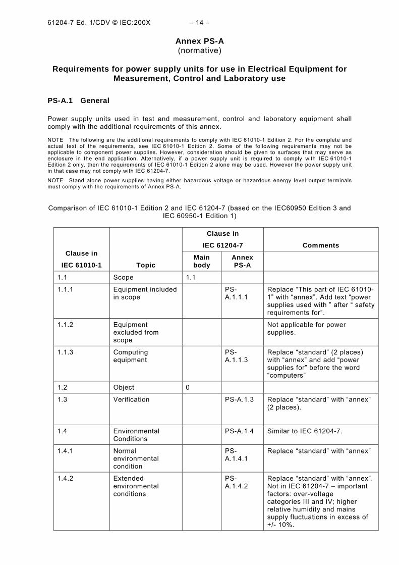
Comparison of IEC 61010-1 Edition 2 and IEC 61204-7 (based on the IEC60950 Edition 3 andIEC 60950-1 Edition 1)
Clause inIEC 61204-7 Comments
Clause inIEC 61010-1 Topic
Mainbody
AnnexPS-A
1.1 Scope 1.1
1.1.1 Equipment includedin scope
PS-A.1.1.1
Replace This part of IEC 61010-1 with annex. Add text powersupplies used with after safetyrequirements for.
1.1.2 Equipmentexcluded fromscope
Not applicable for powersupplies.
1.1.3 Computingequipment
PS-A.1.1.3
Replace standard (2 places)with annex and add powersupplies for before the wordcomputers
1.2 Object 0
1.3 Verification PS-A.1.3 Replace standard with annex(2 places).
1.4 EnvironmentalConditions
PS-A.1.4 Similar to IEC 61204-7.
1.4.1 Normalenvironmentalcondition
PS-A.1.4.1
Replace standard with annex
1.4.2 Extendedenvironmentalconditions
PS-A.1.4.2
Replace standard with annex.Not in IEC 61204-7 importantfactors: over-voltagecategories III and IV; higherrelative humidity and mainssupply fluctuations in excess of+/- 10%.
5.2 PS-A.6.8 Different procedure than used inIEC61204-7
The test in IEC 61010--1 is notneeded except for reducedclearance based uponhomogenous construction that isnot addressed in the main bodyof IEC 61204-7. If reducedclearances are usedrefer to IEC61010-1, section 6.8.
6.8.1 Reference testearth
PS-A.6.8.1
6.8.2 Humiditypreconditioning
PS-A.6.8.2
6.8.3 Conduct of tests PS-A.6.8.3
6.8.4 Voltage tests PS-A.6.8.4
6.8.4.1 Altitude correctionof test voltages forcheckingclearances inhomogeneousconstruction
Annex C Measurement ofclearances andcreepage distances
Annex F
Annex D Parts betweenwhich insulationrequirements arespecified
2.2.3 IEC 61204-7 is more stringent
Annex E Reduction ofpollution degrees
2.10.7 Annex PS-A.E*
* Covered by IEC 61204-7clause 2.10.7 except that for IEC61010-1, coated PWBs are notacceptable for reducing pollutiondegree 3 to 1. Also coated PWBstested to IEC 61204-7 clause2.10.6 are not permitted to usethe separation distances of table2N for use in IEC 61010-1.
Annex F Routine tests Annex PS-A.F
Annex PS-A.F1
Annex PS-A.F2*
Annex PS-A.F3**
* Time is 2 seconds compared to1 second for IEC 61204-7.
**Not applicable to powersupplies
Annex G Leakage andrupture from fluidsunder pressure
Not applicable to power supplies
NOTE 1- Those clauses in the column for Annex PS-A will generally be added in their entirety withappropriate editing to Annex PS-A. If a portion of the clause is indicated, see Note 2.
NOTE 2 - In the comments column, material marked with asterisk(s) is a brief summary of partsof clauses that are to be added to Annex PS-A.
PS-A.1 Scope and Object
PS-A.1.1 Scope
PS-A.1.1.1 Power supplies included in scope
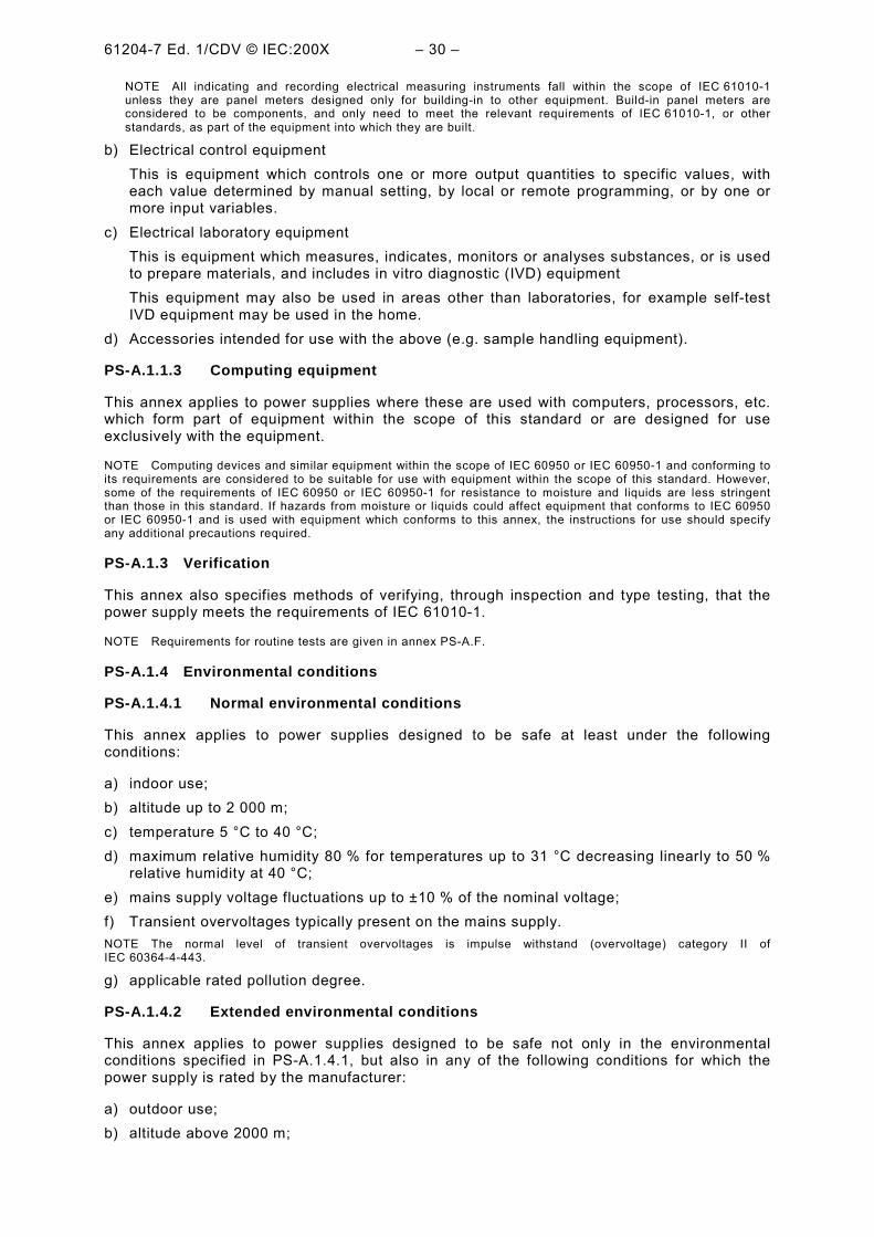
This annex specifies general safety requirements for power supplies intended forprofessional, industrial process, and educational use, any of which may incorporatecomputing devices, as defined in a) to d) below, when used under the environmentalconditions of PS-A.1.4.
a) Electrical test and measurement equipmentThis is equipment which by electrical means tests, measures, indicates or records one ormore electrical or non-electrical quantities, also non-measuring equipment such as signalgenerators, measurement standards, power supplies, transducers, transmitters, etc.
NOTE All indicating and recording electrical measuring instruments fall within the scope of IEC 61010-1unless they are panel meters designed only for building-in to other equipment. Build-in panel meters areconsidered to be components, and only need to meet the relevant requirements of IEC 61010-1, or otherstandards, as part of the equipment into which they are built.
b) Electrical control equipmentThis is equipment which controls one or more output quantities to specific values, witheach value determined by manual setting, by local or remote programming, or by one ormore input variables.
c) Electrical laboratory equipmentThis is equipment which measures, indicates, monitors or analyses substances, or is usedto prepare materials, and includes in vitro diagnostic (IVD) equipmentThis equipment may also be used in areas other than laboratories, for example self-testIVD equipment may be used in the home.
d) Accessories intended for use with the above (e.g. sample handling equipment).
PS-A.1.1.3 Computing equipment
This annex applies to power supplies where these are used with computers, processors, etc.which form part of equipment within the scope of this standard or are designed for useexclusively with the equipment.
NOTE Computing devices and similar equipment within the scope of IEC 60950 or IEC 60950-1 and conforming toits requirements are considered to be suitable for use with equipment within the scope of this standard. However,some of the requirements of IEC 60950 or IEC 60950-1 for resistance to moisture and liquids are less stringentthan those in this standard. If hazards from moisture or liquids could affect equipment that conforms to IEC 60950or IEC 60950-1 and is used with equipment which conforms to this annex, the instructions for use should specifyany additional precautions required.
PS-A.1.3 Verification
This annex also specifies methods of verifying, through inspection and type testing, that thepower supply meets the requirements of IEC 61010-1.
NOTE Requirements for routine tests are given in annex PS-A.F.
PS-A.1.4 Environmental conditions
PS-A.1.4.1 Normal environmental conditions
This annex applies to power supplies designed to be safe at least under the followingconditions:
a) indoor use;b) altitude up to 2 000 m;c) temperature 5 °C to 40 °C;d) maximum relative humidity 80 % for temperatures up to 31 °C decreasing linearly to 50 %
relative humidity at 40 °C;e) mains supply voltage fluctuations up to ±10 % of the nominal voltage;f) Transient overvoltages typically present on the mains supply.NOTE The normal level of transient overvoltages is impulse withstand (overvoltage) category II ofIEC 60364-4-443.
g) applicable rated pollution degree.
PS-A.1.4.2 Extended environmental conditions
This annex applies to power supplies designed to be safe not only in the environmentalconditions specified in PS-A.1.4.1, but also in any of the following conditions for which thepower supply is rated by the manufacturer:
c) ambient temperatures below 5 °C or above 40 °C;d) relative humidity above the levels specified in PS-A.1.4.1;
e) mains supply voltage fluctuations exceeding ±10 % of the nominal voltage.
PS-A.2 Normative references
The following normative documents contain provisions which, through reference in this text,constitute provisions of this annex. For dated references, subsequent amendments to, orrevisions of, any of these publications do not apply. However, parties to agreements based onthis annex are encouraged to investigate the possibility of applying the most recent editions ofthe normative documents indicated below. For undated references, the latest edition of thenormative document referred to applies. Members of ISO and IEC maintain registers ofcurrently valid International Standards.
IEC 60027, Letter symbols to be used in electrical technology
IEC 60335, Safety of household and similar electrical appliances
IEC 60664-3, Insulation coordination for equipment within low-voltage systems Part 3: Useof coatings to achieve insulation coordination of printed board assemblies
IEC 60707, Methods of tests for the determination of the flammability of solid electricalinsulating materials when exposed to an igniting source
IEC 60799, Electrical accessories Cord sets and interconnection cord sets
IEC 60947-1, Low-voltage switchgear and controlgear Part 1: General rules
IEC 60947-3, Low-voltage switchgear and controlgear Part 3: Switches, disconnecters,switch-disconnectors and fuse-combination units
ISO 306:1994, Plastics Thermoplastic materials Determination of Vicat softeningtemperature (VST)
PS-A.3 Terms and definitions
Unless otherwise specified, values of "voltage" and "current" are the r.m.s. values of analternating, direct or composite voltage or current.
Definition in alphabetical order of nouns
Barrier PS-A.3.2.5Body, responsible PS-A.3.5.11Category, overvoltage PS-A.3.7.2Category I, overvoltage PS-A.3.7.2.1Category II, overvoltage PS-A.3.7.2.2Category III, overvoltage PS-A.3.7.2.3Category IV, overvoltage PS-A.3.7.2.4Condition, Normal PS-A.3.5.8Condition, single fault PS-A.3.5.9Co-ordination, insulation PS-A.3.7.1Hazard PS-A.3.5.2Hazardous live PS-A.3.5.3Pollution PS-A.3.7.3
PS-A.3.1.1 fixed power suppliespower supplies fastened to a support, or otherwise secured in a specific location (826-07-07).
PS-A.3.2.1 terminalA component provided for the connection of a power supply to external conductors[IEV 151-01-03].NOTE Terminals can contain one or several contacts and the term therefore includessockets, connectors, etc.
PS-A.3.2.2 functional earth terminalA terminal by which electrical connection is made directly to a point of measuring or controlcircuit or to a screening part and which is intended to be earthed for any functional purposeother than safety.
PS-A.3.2.3 protective conductor terminalA terminal which is bonded to conductive parts of a power supply for safety purposes and isintended to be connected to an external protective earthing system.
PS-A.3.2.5 barrierA part providing protection against direct contact from any usual direction of access.NOTE Enclosures and barriers may provide protection against the spread of fire (see PS-A.9.2.1 b)).
PS-A.3.3.1 rated (value)A quantity value assigned, generally by a manufacturer, for a specified operating condition ofa component power supply or stand alone power supply [IEV 151-04-03].
PS-A.3.3.2 ratingSet of rated values and operating conditions [IEV 151-04--04].
PS-A.3.5.3 hazardous liveCapable of rendering an electric shock or electric burn in normal condition or single faultcondition.NOTE See PS-A.6.3.1 a) and b) for values applicable to normal condition and PS-A.6.3.2 a) and b) for the highervalues deemed to be appropriate in single fault condition.
PS-A.3.5.10 normal conditionCondition in which all means for protection against hazards are intact.
PS-A.3.5.11 single fault conditionCondition in which one means for protection against hazard is defective or one fault is presentwhich could cause a hazard.NOTE If a single fault condition results unavoidably in another single fault condition, the two failures areconsidered as one single fault condition
PS-A.3.5.12 operatorPerson operating the power supply for its intended purpose.
NOTE The operator should have received training appropriate for this purpose.
PS-A.3.5.13 responsible bodyIndividual or group responsible for the use and maintenance of the power supply and forensuring that operators are adequately trained.
PS-A.3.5.14 wet locationLocation where water or another conductive liquid may be present and is likely to causereduced human body impedance due to wetting of the contact between the human body andthe equipment, or wetting of the contact between the human body and the environment.
PS-A.3.6.5 pollutionAddition of foreign matter, solid, liquid or gaseous (ionized gases), that may produce areduction of dielectric strength or surface resistivity.
PS-A.3.6.6 pollution degreeFor the purpose of evaluating spacings, the following degrees of pollution in the micro-environment are defined.
PS-A.3.6.6.1 pollution degree 1No pollution or only dry, non-conductive pollution occurs. The pollution has no influence.
PS-A.3.6.6.2 pollution degree 2Normally only non-conductive pollution occurs. Occasionally, however, a temporaryconductivity caused by condensation must be expected.
PS-A.3.6.6.3 pollution degree 3
Conductive pollution occurs, or dry, non-conductive pollution occurs which becomesconductive due to condensation which is expected.
NOTE In such conditions, power supplies are normally protected against exposure to direct sunlight, precipitation,and full wind pressure, but neither temperature nor humidity is controlled.
PS-A.4.3.1 Environmental conditions
Unless otherwise specified in this standard, the following environmental conditions shall existin the test location:
a) a temperature of 15 °C to 35 °C;b) a relative humidity of not more than 75 %, but not exceeding the limits of PS-A.1.4.1 d);c) an air pressure of 75 kPa to 106 kPa;d) no hoar-frost, dew, percolating water, rain, solar radiation, etc.
PS-A.4.3.2.8 Connections
The power supply shall be connected for its intended purpose, or not connected.
PS-A.4.4.2.2 Protective conductor
The protective conductor shall be interrupted, except for permanently connected powersupplies or power supplies utilizing a connector in accordance with IEC 60309.
PS-A.4.4.2.8 power supplies for more than one supply
power supplies which are designed to be operated from more than one type of supply shall besimultaneously connected to these supplies, unless this is prevented by the construction.
PS-A.4.4.3.1 The power supply shall be operated until further change as a result of theapplied fault is unlikely. Each test is normally limited to 1 h since a secondary fault arisingfrom a single fault condition will usually manifest itself within that time. If there is an indicationthat a risk of electric shock, spread of fire or injury to persons may eventually occur, the testshall be continued until one of these hazards does occur or for a maximum period of 4 h,unless a hazard occurs before then.
PS-A.4.4.3.2 Where a device which interrupts or limits the current during operation isincluded to
limit the temperature of parts which can easily be touched, the maximum temperature attainedby the
power supply shall be measured, whether the device operates or not.
PS-A.4.4.3.3 If a fault is terminated by the opening of a fuse and if the fuse does not operatewithin approximately 1 s, the current through the fuse under the relevant fault condition shallbe measured. Evaluation with the pre-arcing time/current characteristics shall be made to findout whether the minimum operating current of the fuse is reached or exceeded and what isthe maximum time before the fuse operates. The current through the fuse may vary as afunction of time.If the minimum operating current of the fuse is not reached in the test, the power supply shallbe operated for a period corresponding to the maximum fusing time or continuously for theduration specified in PS-A.4.4.3.1.
If a fault is terminated by the opening of a fuse and if the fuse does not operate withinapproximately 1 s, the current through the fuse under the relevant fault condition shall bemeasured. Evaluation with the pre-arcing time/current characteristics shall be made to findout whether the minimum operating current of the fuse is reached or exceeded and what isthe maximum time before the fuse operates. The current through the fuse may vary as afunction of time.
If the minimum operating current of the fuse is not reached in the test, the power supply shallbe operated for a period corresponding to the maximum fusing time or continuously till theconditions stabilize.
PS-A.4.4.4 Conformity after application of fault conditions
PS-A.4.4.4.1 Conformity with requirements for protection against electric shock is checkedafter the application of single faults as follows:
a) by making the measurements of PS-A.6.3.2 a) and b) to check that no accessibleconductive parts have become hazardous live;
b) by performing a voltage test on double insulation or reinforced insulation to check thatthere is still one level of protection by insulation. The voltage test is made as specified inPS-A.6.8 (without conformity preconditioning) with the test voltage for basic insulation.
c) by measuring the temperature of transformer windings if the protection against electricalhazards is achieved by double insulation or reinforced insulation within the transformer.The temperatures of 5.3.8.1/RD shall not be exceeded.
PS-A.4.4.4.2 Conformity with requirements for temperature protection is checked bydetermining the temperature of the outer surface of the enclosure and of parts which caneasily be touched.
Except for heated surfaces of heating equipment, the temperature of these parts shall notexceed 105 °C at an ambient temperature of 40 °C or the maximum rated ambienttemperature if higher.
This temperature is determined by measuring the temperature rise of the surface or part andadding it to 40 °C or the maximum rated ambient temperature if higher.
PS-A.4.4.4.3 Conformity with requirements for protection against the spread of fire ischecked by placing the power supply on white tissue-paper covering a softwood surface andcovering the power supply with cheesecloth. No molten metal, burning insulation, flamingparticles, etc. shall fall on the surface on which the power supply stands and there shall be nocharring, glowing, or flaming of the tissue paper or cheesecloth. Melting of insulation materialshall be ignored if no hazard could arise.
PS-A.4.4.4.4 Conformity with requirements for protection against other hazards is checkedas specified in PS-A.7.1, PS-A.8, PS-A.11.5, PS-A.14.5 and PS-A.14.8.
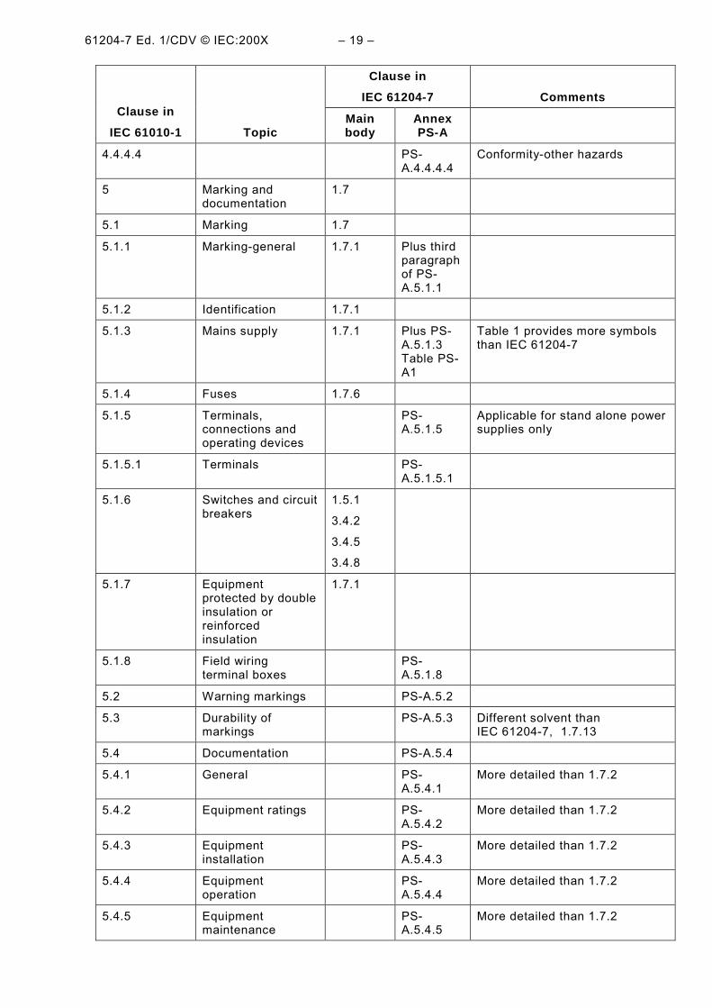
PS-A.5.1.1 General
Letter symbols for quantities and units shall be in accordance with IEC 60027. Graphicsymbols shall be in accordance with Table PS-A1 if applicable. There are no colourrequirements for symbols. Graphic symbols shall be explained in the documentation.
NOTE Markings should not be on the bottom of the power supply, except where space is limited.
Conformity is checked by inspection.
PS-A.5.1.3 Mains supply
The power supply shall be marked with the following information:
a) nature of supply:1) a.c.: rated mains frequency or range of frequencies;2) d.c.: symbol 1 of Table PS-A1;
NOTE 1 For information purposes it may be useful to mark:
power supplies intended for a.c. with symbol 2 of Table PS-A1; power supplies suitable for both a.c. and d.c. with symbol 3 of Table PS-A1; power supplies for three-phase supply with symbol 4 of Table PS-A1.
b) the rated value(s) of the supply voltage(s) or the rated range of the supply voltages;NOTE 2 rated voltage fluctuations may also be marked.
c) the maximum rated power in watts (active power) or volt-amperes (apparent power), or themaximum rated input current, with all accessories or plug-in modules connected. If thepower supply can be used on more than one voltage range, separate values shall bemarked for each voltage range unless the maximum and minimum values do not differ bymore than 20 % of the mean value;
d) power supplies which the operator can set for different rated supply voltages shall beprovided with means for the indication of the voltage for which the power supply is set. Forportable power supplies the indication shall be visible from the exterior. If the powersupply is so constructed that the supply voltage setting can be altered without the use of atool, the action of changing the setting shall also change the indication;
e) accessory mains socket-outlets accepting standard mains plugs shall be marked with thevoltage if it is different from the mains supply voltage. If the outlet is for use only withspecific equipment, it shall be marked to identify the equipment for which it is intended. Ifnot, the maximum rated current or power shall be marked, or symbol 14 of Table PS-A1placed beside the outlet with the full details included in the documentation.Conformity is checked by inspection and by measurement of power or input current tocheck the marking of PS-A.5.1.3 c)). The measurement is made after the current hasreached a stationary stage (usually after 1 min) so as to exclude any initial inrush current.The power supply shall be in the condition of maximum power consumption. Transientsare ignored. The measured value shall not exceed the marked value by more than 10 %.
IEC 60417, No. 5269 Out position of a bistable push control
NOTE See PS-A.5.4.1 which requires manufacturers to state that documentation must be consulted in allcases where this symbol is marked.
PS-A.5.1.5 Terminals, connections and operating devices
If necessary for safety, an indication shall be given of the purpose of terminals, connectors,controls, and indicators, including any connections for fluids such as gas, water and drainage.Where there is insufficient space, symbol 14 of Table PS-A1 may be used.
NOTE 1 For additional information, see IEC 60445 and IEC 60447.
NOTE 2 Individual pins of multi-pin connectors need not be marked.
PS-A.5.1.5.1 Terminals
Terminals for connection to the mains supply shall be identifiable.
The following terminals shall be marked as follows:
a) functional earth terminals with symbol 5 of Table PS-A1;b) protective conductor terminals with symbol 6 of Table PS-A1, except when the protective
conductor terminal is part of an approved mains appliance inlet. The symbol shall beplaced close to or on the terminal;
c) terminals of measuring and control circuits which are permitted by PS-A.6.6.3 to beconnected to accessible conductive parts with symbol 7 of Table PS-A1 if this connectionis not self-evident;
NOTE This symbol may also be considered as a warning symbol in that it indicates that a hazardous livevoltage must not be connected to the terminal. The symbol should also be used if it is likely that the operatorcould make such a connection inadvertently.
d) terminals supplied from the interior of the equipment and which are hazardous live, withthe voltage, current, charge or energy value or range, or with symbol 14 of Table PS-A1.This requirement does not apply to mains supply outlets where a standard mains socketoutlet is used;
e) accessible functional earth terminals connected to accessible conductive parts, with anindication that this is the case, unless it is self-evident. Symbol 8 of Table PS-A1 isacceptable for this marking.
Conformity is checked by inspection.
PS-A.5.1.8 Field-wiring terminal boxes
If the temperature of the terminals or the enclosure of a field-wiring terminal box orcompartment exceeds 60 °C in normal condition at an ambient temperature of 40 °C, or themaximum rated ambient temperature if higher, there shall be a marking of the minimumtemperature rating of the cable to be connected to the terminals. The marking shall be visiblebefore and during connection, or be beside the terminals.
Conformity, in case of doubt, is checked by measurement as specified in PS-A.10.3 a) and, ifapplicable, by inspection of markings.
PS-A.5.2 Warning markings
Warning markings shall be visible when the stand alone power supply (does not apply tocomponent power supplies) is ready for normal use. If a warning applies to a particular part ofthe stand alone power supply, the marking shall be placed on or near to this part.
a) Symbols shall be at least 2,75 mm high. Text shall be at least 1,5 mm high and contrastingin colour with the background.
b) Symbols or text moulded, stamped or engraved in a material shall be at least 2,0 mm high.If not contrasting in colour, they shall have a depth or raised height of at least 0,5 mm.
If it is necessary for the responsible body or operator to refer to the instruction manual topreserve the protection afforded by the power supply, the power supply shall be marked withsymbol 14 of Table PS-A11. Symbol 14 is not required to be used with symbols which areexplained in the manual.
If the instructions for use state that an operator is permitted to gain access, using a tool, to apart which in normal use may be hazardous live, there shall be a warning marking whichstates that the power supply must be isolated or disconnected from the hazardous live voltagebefore access.
Warning markings are specified in PS-A.5.1.5.1 c), PS-A.6.1.2 b), PS-A.6.6.2, 4.4.2/RD,4.1/RD, PS-A.10.1, PS-A.13.2.2.
Conformity is checked by inspection.
PS-A.5.3 Durability of markings
Markings in accordance with 1.7.1/RD, PS-A.5.1.3, table PS-A1, PS-A.5.1.5, PS-A.5.1.5.1,PS-A.5.1.8 and PS-A.5.2 shall remain clear and legible under conditions of normal use andresist the effects of cleaning agents specified by the manufacturer.
Conformity is checked by inspection and by performing the following test for durability ofmarkings on the outside of the powersupply. The markings are rubbed by hand, without unduepressure, for 30 s with a cloth soaked with the specified cleaning agent (or, if not specified,with isopropyl alcohol).
The markings shall be clearly legible after the above treatment, and adhesive labels shall nothave worked loose or become curled at the edges
PS-A.5.4 Documentation
PS-A.5.4.1 General
Power supplies shall be accompanied by documentation for safety purposes as follows:
a) intended use of the power supply;b) technical specification;c) instructions for use;d) name and address of manufacturer or supplier from whom technical assistance may be
obtained;e) the information specified in PS-A.5.4.2 to PS-A.5.4.5;
not applicable to power suppliesf) not applicable to power supplies
If applicable, warning statements and a clear explanation of warning symbols marked onthe power supply shall be provided in the documentation or shall be durably and legiblymarked on the power supply. In particular, there shall be a statement that documentationneeds to be consulted in all cases where symbol 14 of Table PS-A1 is used, in order tofind out the nature of the potential hazard and any actions which have to be taken.
a) the supply voltage or voltage range, frequency or frequency range, and power or currentrating;
b) a description of all input and output connections;c) the rating of the insulation of external circuits, appropriate for single fault conditions, if
such circuits are nowhere accessible (see PS-A.6.6.2);d) a statement of the range of environmental conditions for which the equipment is designed
(see PS-A.1.4);e) a statement of the degree of protection, if the equipment is rated according to IEC 60529.
Conformity is checked by inspection.
PS-A.5.4.3 Power supply installation
The documentation shall include installation and specific commissioning instructions(examples are listed below) and if necessary for safety, warnings against hazards which couldarise during installation or commissioning of the power supply:
a) assembly, location and mounting requirements;b) instructions for protective earthing;c) connections to the supply;d) for permanently connected power supplies:
1) supply wiring requirements;2) requirements for any external switch or circuit-breaker (see 3.4.3/RD) and external
overcurrent protection devices (see 2.7.1/RD) and a recommendation that the switch orcircuit-breaker be near the power supply;
e) ventilation requirements;f) requirements for special services, for example air, cooling liquid;g) not applicableh) not applicablei) not applicable
Conformity is checked by inspection.
PS-A.5.4.4 Power supply operation
Instructions for use shall include, if applicable:
a) identification of operating controls and their use in all operating modes;b) an instruction not to position the power supply so that it is difficult to operate the
disconnecting device;c) instructions for interconnection to other equipment, including indication of detachable
parts and any special materials;d) specification of limits for intermittent operation;e) an explanation of symbols related to safety which are used on the power supply;f) not applicable;g) not applicable;h) not applicablei) not applicable
There shall be a statement in the instructions that, if the power supply is used in a manner notspecified by the manufacturer, the protection provided by the power supply may be impaired.
Instructions for the responsible body concerning preventive maintenance and inspectionnecessary for safety shall be given in sufficient detail.
NOTE Instructions should advise the responsible body of any tests necessary to check that power supply is stillin a safe condition. They should also warn against the repetition of any tests of this standard which could damagethe power supply and reduce protection against hazards.
For power supplies using replaceable batteries, the specific battery type shall be stated.
The manufacturer shall specify any parts which are required to be examined or supplied onlyby the manufacturer or his agent.
The rating and characteristics of replaceable fuses shall be stated.
Conformity is checked by inspection.
PS-A.6.1.2 Exceptions (from protection against electric shock)
If it is not feasible for operating reasons to prevent the following parts being both accessibleand hazardous live, they are permitted to be accessible to the operator during normal usewhile they are hazardous live:
a) parts of lamps and lamp sockets after lamp removal;b) parts intended to be replaced by the operator (e.g. batteries) and which may be hazardous
live during the replacement or other operator action, but only if they are accessible only bymeans of a tool and have a warning marking (see PS-A.5.2);
c) locking and screw-held type measuring terminals, including terminals which do not requirethe use of a tool.
If any of the parts in a) and b) receive a charge from an internal capacitor, they shall not behazardous live 10 s after interruption of the supply.
If a charge is received from an internal capacitor, conformity is checked by the measurementsof PS-A.6.3 to establish that the levels of 2.4.2/RD are not exceeded.
PS-A.6.2.2 Openings above parts that are hazardous live
A metal test pin 100 mm long and 4 mm in diameter is inserted in any openings above partswhich are hazardous live. The test pin is suspended freely and allowed to penetrate up to100 mm. The additional safety measures of PS-A.6.5. for protection in single fault conditionare not required solely because a part is accessible by this test only. This test is not appliedto terminals.
PS-A.6.2.3 Openings for pre-set controls
A metal test pin 3 mm in diameter is inserted through holes intended to give access to pre-setcontrols which require the use of a screwdriver or other tool. The test pin is applied in everypossible direction through the hole. Penetration shall not exceed three times the distancefrom the enclosure surface to the control shaft or 100 mm, whichever is smaller.
PS-A.6.3 Permissible limits for accessible parts
The voltage, current, charge or energy between an accessible part and reference test earth,or between any two accessible parts on the same piece of equipment within a distance of1,8 m (over a surface or through air), shall not exceed the values of PS-A.6.3.1 in normalcondition nor of PS-A.6.3.2 in single fault condition.
The following values apply to accessible circuits in wet locations only. The values for drylocations are covered by 2.2.2/RD.
Values above the following levels in normal condition are deemed to be hazardous live. Thelimits of PS-A.6.3.1 b) and c) apply only if the voltage exceeds the values of PS-A.6.3.1 a).
a) For power supplies rated for use in wet locations, the voltage levels are 16 V r.m.s. and22,6 V peak or 35 V d.c.
b) The current levels are:1) 0,5 mA r.m.s. for sinusoidal waveforms, 0,7 mA peak for non-sinusoidal waveform or
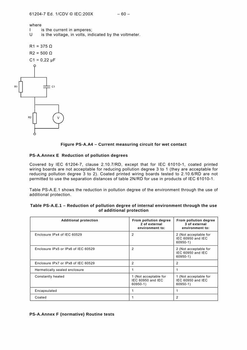
mixed frequencies, or 2 mA d.c., when measured with the measuring circuit ofFigure D.1/RD. Alternatively the measuring circuit of Figure D.1/RD can be used if thefrequency does not exceed 100 Hz.The measuring circuit of Figure PS-A.A.4 is usedfor power supplies rated for use in wet locations.
2) 70 mA r.m.s. when measured with the measuring circuit of Figure D.1/RD. This relatesto possible burns at higher frequencies.
c) Limits of 2.4.2/RD apply.
PS-A.6.3.2 Values in single fault condition
The following values apply to accessible circuits in wet locations only. The values for drylocations are covered by 2.2.3/RD.
Values above the following levels in single fault condition are deemed to be hazardous live.The limits of PS-A.6.3.2 b) and c) apply only if the voltage exceeds the values of PS-A.6.3.2a).
a) For power supplies rated for use in wet locations, the voltage levels are 33 V r.m.s. and46,7 V peak or 70 V dc. For temporary voltages, the levels are those of Figure PS-A1,measured across a 50 kΩ resistor (use curves A and C only in Figure PS-A1).
b) The current levels are:1) 3,5 mA r.m.s. for sinusoidal waveforms, 5 mA peak for non-sinusoidal waveforms or
mixed frequencies, or 15 mA d.c., when measured with the measuring circuit ofFigure D.1/RD. Alternatively, the measuring circuit of Figure D.1/RD can be used if thefrequency does not exceed 100 Hz. The measuring circuit of Figure PS-A.A.4 is usedfor power supplies rated for use in wet locations;
1) the determination of 2.1.1/RD, PS-A.6.2.2 and PS-A.6.2.3, and the measurements of PS-A.6.3.1 a) and b), to establish that accessible conductive parts are not hazardous live;
2) inspection or measurement of clearances and creepage distances as specified in PS-A.6.7;
3) the tests of PS-A.6.8 for dielectric strength of basic insulation;4) the tests of 4.2.5/RD and PS-A.8 for rigidity of enclosures and barriers.
PS-A.6.5.1.1 Integrity of protective bonding
The integrity of protective bonding shall be assured by the following means.
a) Protective bonding shall consist of directly connected structural parts or discreteconductors, or both. It shall withstand all thermal and dynamic stresses to which it couldbe subjected before one of the over-current protective means specified in 2.7/RDdisconnects the equipment from the supply.
d) Movable conductive connections, for example, hinges, slides, etc., shall not be the soleprotective bonding path unless they are specifically designed for electrical inter-connection and meet the requirements of PS-A.6.5.1.3.
e) The exterior metal braid of cables, even if connected to the protective conductor terminal,shall not be regarded as protective bonding.
f) If power from the mains supply is passed through power supply for use by otherequipment, means shall also be provided for passing the protective conductor through thepower supply to protect the other equipment. The impedance to the protective conductorpath through the equipment shall not exceed that specified in PS-A.6.5.1.3.
h) Power supplies using protective bonding shall be provided with a terminal meeting therequirements of PS-A.6.5.1.2 and suitable for connection to a protective conductor.
Conformity is checked by inspection.
PS-A.6.5.1.2 Protective conductor terminalj) If the protective conductor terminal is a binding screw it shall be of a suitable size for the
bond wire, but no smaller than M 4 (No. 6), with at least three turns of the screw engaged.The contact pressure required for a bonding connection shall not be capable of beingreduced by deformation of materials forming part of the connection.
Conformity is checked by inspection and by the following test. The assembly of a screw in ametal part or nut, together with the least favourable grounding conductor to be secured, andany associated conductor securing means shall withstand, without mechanical failure, threeoperations of assembly and disassembly when using the tightening torques specified in TablePS-A2.
Table PS-A2 – Tightening torque for screw assemblies
Size of screw (mm) 4,0 5,0 6,0 8,0 10,0
Tightening torque(N·m)
1,2 2,0 3,0 6,0 10,0
PS-A.6.5.1.3 Impedance of protective bonding
For power supplies rated 16 A or less, conformity is checked by applying a test current for 1min and then calculating impedance. The test current is the greater of:
a) 25 A d.c. or a.c. r.m.s. at rated mains frequency;b) a current equal to twice the rated current of the equipment.
If the power supply contains overcurrent protection devices for all poles of the mains supply,and if the wiring on the supply side of the overcurrent protection devices cannot become
connected to accessible conductive parts in the case of a single fault, the test current neednot be more than twice the rated current of the internal overcurrent protection devices.
For power supplies rated above 16 A, 2.6.3.3 of IEC 60950 or 2.6.3.4 of IEC 60950-1applies.
PS-A.6.5.2 Double insulation and reinforced insulation
Clearances and creepage distances forming part of double insulation or reinforced insulationshall meet the applicable requirements of PS-A.6.7 (see 2.2.3/RD and 2.9.5/RD). Enclosuresshall meet the requirements of 1.2.4.2/RD, 2.2.3/RD and 2.9.5/RD..
Solid insulation forming part of reinforced insulation shall pass the voltage test of PS-A.6.8with the values for reinforced insulation.
Conformity is checked as specified in PS-A.6.7 (see 2.2.3/RD and 2.9.5/RD), PS-A.6.8 and1.2.4.2/RD, 2.2.3/RD and 2.9.5/RD. The parts of double insulation are tested separately if thisis possible; the tests for reinforced insulation are otherwise used. Clearances and creepagedistances necessary for safety can be checked by measurement.
PS-A.6.5.4 Automatic disconnection of the supply
If automatic disconnection of the supply is used for protection in single fault condition, theautomatic disconnection device shall meet all the following requirements.
a) It shall be supplied with the power supply or the installation instructions shall specify thedevice to be fitted as part of the installation.
b) It shall be rated to disconnect the load within the time specified in 2.4.2/RD for drylocations and Figure PS-A1 for wet locations.
c) It shall be rated for the maximum rated load conditions of the power supply.
Conformity is checked by inspection of the device specification and, if applicable, installationinstructions. In case of doubt the device is tested to check that it disconnects the supplywithin the required time.
PS-A.6.6.2 Terminals for external circuits
This applies to stand alone power supplies only.
Terminals which receive a charge from an internal capacitor shall not be hazardous live 10 safter interruption of the supply.
Terminals which are energized from the interior, with hazardous live voltage exceeding1 kV r.m.s. or 1,5 kV d.c., or with floating voltage exceeding 1 kV r.m.s. or 1,5 kV d.c., shallnot be accessible. Power supplies with such terminals shall be designed so that an accessiblehazardous live voltage is not present when connectors are not mated, or shall be marked withsymbol 12 of Table PS-A1 (see PS-A.5.2) to warn the operator of the possible presence of anaccessible hazardous live voltage.
Unmated measuring terminals which are hazardous live when the maximum rated voltage isapplied to the terminal shall not be accessible.
NOTE For locking and screw-held terminals, see PS-A.6.1.2 c).
Conformity is checked by inspection, and by the determination of accessible parts asspecified in PS-A.6.2.2 and PS-A.6.2.3.
PS-A.6.6.3 Circuits with terminals which are hazardous live
These circuits shall not be connected to accessible conductive parts, except for circuits whichare not mains circuits, and which are designed to be operated with one terminal contact atearth potential. In such cases, the accessible conductive parts shall not be hazardous live.
If such a circuit is also designed to be operated with one accessible terminal contact (signallow) floating at a voltage which is not hazardous live, this terminal contact is permitted to beconnected to a common functional earth terminal or system (for example a coaxial screeningsystem). This common functional earth terminal or system is also permitted to be connectedto other accessible conductive parts.
Conformity is checked by inspection.
PS-A.6.7 Clearances and creepage distances
Clearances and creepage distances are specified in 2.10.3/RD, 2.10.4/RD, PS-A.6.7.3.1, PS-A.6.7.3.2 and PS-A.6.7.3.3 so as to withstand the voltages that appear on the system forwhich the power supply is intended. They also take account of rated environmental conditionsand of any protective devices fitted within the power supply or required by the manufacturersinstructions.
There are no clearance or creepage distance requirements for the interior of void-freemoulded parts, including the inner layers of multi-layer printed circuit boards.
Conformity is checked by inspection and measurement. When determining a clearance orcreepage distance to accessible parts, the accessible surface of an insulating enclosure isconsidered to be conductive as if it was covered by metal foil wherever it can be touched witha standard test finger (see 2.1.1/RD). Conformity for homogeneous construction is checked asspecified in PS-A.6.7.3.1 c).
PS-A.6.7.3 Circuits other than mains circuits
PS-A.6.7.3.1 Clearance values – general
This is permitted only if the secondary circuits are connected to protective earth or isolatedfrom the primary circuit by a metal screen connected to protective earth. Otherwise, therequirements of 2.10.3/RD apply.
a) For circuits derived from mains circuits, clearances shall have the values as specified inTable PS-A5 except for the conditions specified in b) below.
b) Clearances for the following cases are specified in PS-A.6.7.3.2. Such cases includeclearances where:1) means have been taken within the equipment which limit overvoltages to levels below
the applicable impulse withstand voltage of Table PS-A5;2) the maximum possible transient overvoltage is above the applicable impulse withstand
voltage of Table PS-A5;3) the working voltage is the sum of voltages from more than one circuit, or is a mixed
voltage;4) it is controlled by the source (external to the equipment, but as specified by the
manufacturer) to levels below the impulse withstand voltage.of Table PS-A5, providedthat the power supply is not intended for connection to other sources which wouldpermit higher impulse voltages.
Table PS-A5 – Clearances for circuits derived from mains circuits
Workingvoltage
Clearance
a.c. r.m.s.
or d.c.
Mains voltage≤≤≤≤100 V
Rated impulsevoltage500 V
Mains voltage>>>>100 V ≤≤≤≤150 V
Rated impulsevoltage800 V
Mains voltage>>>>150 V ≤≤≤≤300 V
Rated impulsevoltage1 500 V
Mains voltage>>>>300 V ≤≤≤≤600 V
Rated impulsevoltage2 500 V
V mm mm mm mm
50
100
150
300
600
1 000
1 250
1 600
2 000
2 500
3 200
4 000
5 000
6 300
8 000
10 000
12 500
16 000
20 000
25 000
32 000
40 000
50 000
63 000
0,05
0,07
0,10
0,24
0,79
1,66
2,23
3,08
4,17
5,64
7,98
10,6
13,7
17,8
23,5
30,3
39,1
52,0
67,4
87,4
117
151
196
258
0,12
0,13
0,16
0,39
1,01
1,92
2,50
3,39
4,49
6,02
8,37
10,9
14,0
18,2
23,9
30,7
39,6
52,5
67,9
87,9
117
151
196
258
0,53
0,61
0,69
0,94
1,61
2,52
3,16
4,11
5,30
6,91
9,16
11,6
14,9
19,1
24,7
31,6
40,5
53,5
68,9
89,0
118
153
198
260
1,51
1,57
1,64
1,83
2,41
3,45
4,16
5,21
6,48
8,05
10,2
12,8
16,1
20,3
26,0
32,9
41,9
54,9
70,5
90,6
120
154
199
261
PS-A.6.7.3.2 Clearance values where Table PS-A5 does not apply
Clearances for basic insulation and supplementary insulation are determined from thefollowing formula:
Clearance = D1 + F(D2 - D1)
where:D1 and D2 are clearances taken from Table PS-A6;D1 is the clearance that would be applicable to the maximum voltage UM if it consisted only of
a 1.2 x 50 µs impulse;D2 is the clearance that would be applicable to the maximum voltage Um if it consisted only of
the peak working voltage UW, without any transient overvoltage;The maximum voltage (Um) is the maximum peak working voltage Uw plus the maximumtransient overvoltage Ut;
F is a factor, determined from one of the equations:
F = 0 if UW / Um ≤ 0.2Clearances for reinforced insulation are calculated using the same formula, but using thevalues of D1 and D2 specified in Table PS-A6 for a voltage 1,6 times the actual workingvoltage.
NOTE The following are two examples:
a) Clearance for reinforced insulation for a peak working voltage of 3500 V and a maximum transientovervoltage of 4 500 V.
b) Clearance for basic insulation for a secondary peak working voltage of 400 V derived from a primaryvoltage of 230 V a.c, but with overvoltage controlled within the equipment to a maximum of 2100 V.
UM = UW + Ut = (400 + 2 100) V = 2500 V
Uw/Um) < 0,2, so F = 0
Clearance = D1 = 1,45 mm.
Table PS-A6 – Clearance values for the calculation of PS-A.6.7.3.2
Ûm CLEARANCE Ûm CLEARANCE
D1 D2 D1 D2
V mm mm V mm mm
14,1 to 266
283
330
354
453
500
566
707
800
891
1 130
1 410
1 500
1 770
2 260
2 500
2 830
3 540
0,010
0,010
0,010
0,013
0,027
0,036
0,052
0,081
0,099
0,12
0,19
0,38
0,45
0,75
1,25
1,45
1,74
2,44
0,010
0,013
0,020
0,025
0,052
0,071
0,10
0,20
0,29
0,41
0,83
1,27
1,40
1,79
2,58
3,00
3,61
5,04
4 000
4 530
5 660
6 000
7 070
8 000
8 910
11 300
14 100
17 700
22 600
28 300
35 400
45 300
56 600
70 700
89 100
100 000
2,93
3,53
4,92
5,37
6,86
8,25
9,69
12,9
16,7
21,8
29,0
37,8
49,1
65,5
85,0
110
145
165
6,05
7,29
10,1
10,8
13,1
15,2
17,2
22,8
29,5
38,5
51,2
66,7
86,7
116
150
195
255
290
NOTE 1 - Interpolation of clearances is allowed.
NOTE 2 - Minimum clearance for pollution degree 2 is 0,2 mm, for pollution degree 3 is 0,8 mm.
a) any protective conductor terminal or functional earth terminal;b) any accessible conductive part, except for any live parts permitted to be accessible
because they do not exceed the values of PS-A.6.3.1 a) and b). Such live parts arebonded together but do not form part of the reference test earth. Also excluded areaccessible conductive parts which are allowed to be hazardous live by the exceptions ofPS-A.6.1.2 b) and c);
c) any accessible insulating part of the enclosure, covered with metal foil everywhere exceptaround terminals. For test voltages up to 10 kV a.c. peak or d.c. the distance from foil toterminal is not more than 20 mm. For higher voltages the distance is the minimum toprevent flashover;
d) accessible parts of controls with parts made of insulating material being wrapped in metalfoil or having soft conductive material pressed against them.
PS-A.6.8.2 Humidity preconditioning
To ensure that power supply will not become hazardous in the humidity conditions of PS-A.1.4, it is subjected to humidity preconditioning before the voltage tests of PS-A.6.8.4. Thepower supply is not operated during preconditioning.
If wrapping in foil is required by PS-A.6.8.1, the foil is not applied until after humiditypreconditioning and recovery.
Electrical components, covers, and other parts which can be removed by hand are removedand subjected to the humidity preconditioning together with the main part.
Preconditioning is carried out in a humidity chamber containing air with a humidity of92,5 % RH ± 2,5 % RH. The temperature of the air in the chamber is maintained at40 °C ± 2 °C.
Before applying humidity, the power supply is brought to a temperature of 42 °C ± 2 °C,normally by keeping it at this temperature for at least 4 h before the humidity preconditioning.
The air in the chamber is stirred and the chamber is designed so that condensation will notprecipitate on the equipment.
The power supply remains in the chamber for 48 h, after which it is removed and allowed arecovery period of 2 h under the environmental conditions of PS-A.4.3.1, with the covers ofnon-ventilated power supplies removed.
PS-A.6.8.3 Conduct of tests
The tests specified in PS-A.6.8.4 are performed and completed within 1 h of the end of therecovery period after humidity preconditioning. The power supply is not operated during thetests.
Voltage tests are not made between two circuits, or between a circuit and an accessibleconductive part, if they are connected to each other or not separated from each other.
Protective impedance and voltage limiting devices in parallel with the insulation to be testedmay be disconnected.
Where two or more protective means are used in combination (see 2.2.3/RD, PS-A.6.6.2 andPS-A.6.6.3), the voltages specified for double insulation and reinforced insulation could beapplied to parts of circuits which are not required to withstand these voltages. To avoid this,such parts may be disconnected during the tests, or the parts of circuits where doubleinsulation or reinforced insulation is required may be tested separately.
Voltage tests are applied, using the values specified in Table PS-A9. No breakdown orrepeated flashover shall occur. Corona effects and similar phenomena are disregarded.
For solid insulation, the a.c. and d.c. tests are alternative test methods. It is sufficient that theinsulation passes either of the two. The tests are conducted with the voltage raised graduallyover a period of 5 s or less to the specified value so that no appreciable transients occur, thenmaintained for 5 s.
NOTE 1 When testing circuits, it may not be possible to separate tests of clearance from tests of solid insulation.
NOTE 2 The maximum test current of test equipment is usually limited to avoid hazards arising from the test anddamage to the power supply which fails the test.
NOTE 3 It may be useful to make partial discharges within the insulation material perceptible (see IEC 60270).
NOTE 4 Care should be taken to discharge stored energy after test.
PS-A.6.9 Constructional requirements for protection against electric shock
PS-A.6.9.1 General
If a failure could cause a hazard:
b) screws securing removable covers shall be captive if their length determines a CLEARANCEor CREEPAGE DISTANCE between accessible conductive parts and hazardous live parts.
PS-A.6.9.3 Over-range indication
If a hazard could arise from an operator's reliance on the value (for example, voltage)displayed by the stand alone power supply, the display shall give an unambiguous indicationwhenever the value is above the maximum positive value or below the minimum negativevalue of the range to which the instrument is set.
NOTE - Examples of hazardous indications include the following, unless there is a separate unambiguousindication of an over-range value:
a) analogue meters with stops at the exact ends of the range;
b) digital meters which show a low value when the true value is above the range maximum (for example1 001,5 V displayed as 001,5 V);
Conformity is checked by inspection and, in case of doubt, by provoking an over-range value.
PS-A.6.10.1 Mains supply cords
The following requirements apply to non-detachable mains supply cords and to detachablemains supply cords supplied with the power supply.
b) If a cord is likely to contact hot external parts of the power supply, it shall be made ofsuitably heat-resistant material.
c) If the cord is detachable, both the cord and the appliance inlet shall have at least thehighest temperature rating for either part.NOTE The requirement for an equal temperature rating for both cord and the appliance inlet ensures thatcord sets of low temperature rating cannot be used inadvertently.
PS-A.6.10.2 Fitting of non-detachable mains supply cords
Conformity is checked by inspection and the following push-pull test: the cord is pushed intothe power supply manually, as far as possible. It is then subjected 25 times to a steady pull ofthe value shown in Table PS-A11, applied for 1 s each time in the least favourable direction.Immediately afterwards it is subjected for 1 min to a torque of the value shown in Table PS-A11.
Table PS-A11 – Physical tests on power supply cords
Mass of equipment
kg
Pull
N
Torque
N·m
≤1 30 0,10>1 ≤4 60 0,25
>4 100 0,35
After the tests:
1) the cord shall not have been damaged;2) the cord shall not have been displaced longitudinally by more than 2 mm;3) there shall be no signs of strain at the point where the anchorage clamps the cord;4) clearances and creepage distances shall not have been reduced below the applicable
values;5) the cord shall pass the voltage test of PS-A.6.8.
PS-A.6.11.3.2 Appliance couplers and plugs
If an appliance coupler or separable plug is used as the disconnecting device, it shall bereadily identifiable and easily reached by the operator. For single-phase portable equipment,a plug on a cord of length not greater than 3 m is considered to be easily reached. Theprotective earth conductor of an appliance coupler shall be connected before the supplyconductors and disconnected after them.
Conformity is checked by inspection.
PS-A.7 Protection against mechanical hazards
PS-A.7.1 General
Operation shall not lead to a mechanical hazard in normal condition or single fault condition.
PS-A.7.4 Provisions for lifting and carrying
If carrying handles or grips are fitted to or supplied with the equipment they shall be capableof withstanding a force of four times the weight of the power supply.
Power supplies or parts having a mass of 18 kg or more shall be provided with a means forlifting and carrying or directions shall be given in the manufacturer's documentation.
Conformity is checked by inspection and by the following test.
A single handle or grip is subjected to a force corresponding to four times the weight of theequipment. The force is applied uniformly over a 7 cm width at the centre of the handle orgrip, without clamping. The force is steadily increased so that the test value is attained after10 s and maintained for a period of 1 min.
If more than one handle or grip is fitted, the force is distributed between the handles or gripsin the same proportion as in normal use. If the power supply is fitted with more than onehandle or grip but is so designed that it may readily be carried by only one handle or grip,each handle or grip shall be capable of sustaining the total force.
The handles or grips shall not break loose from the power supply and there shall not be anypermanent distortion, cracking or other evidence of failure.
PS-A.7.5 Wall mounting
Mounting brackets on power supplies intended to be mounted on a wall or ceiling shallwithstand a force of four times the weight of the power supply.
Conformity is checked after mounting the power supply in accordance with the manufacturer'sinstructions, using the fasteners and wall construction specified. Adjustable brackets areadjusted to the position that will give the maximum projection from the wall.
If no wall construction is specified, a 10 mm ± 2 mm thick plaster board (drywall) on nominal50 mm x 100 mm ± 10 mm studs at 400 mm ± 10 mm centres is to be used as the supportsurface. Fasteners are applied as specified in the instructions, but if not specified arepositioned in the plasterboard between the studs.
The mounting brackets are then subjected to the weight of the power supply plus a test weightof three times the weight of the power supply, acting vertically through the centre of gravity.The test weight is applied gradually and is increased from zero to full load in 5 s to 10 s, thenmaintained for 1 min.
After the test, there shall be no damage to the bracket or the mounting surface.
PS-A.8 Mechanical resistance to shock and impact
Power supplies shall not cause a hazard when subjected to shock and impact likely to occurin normal use. Power supplies shall have adequate mechanical strength, components shall bereliably secured, and electrical connections shall be secure.
Conformity is checked by performing the tests of PS-A.8.1 and, except for fixed powersupplies, the appropriate test of PS-A.8.2. The power supply is not operated during the tests.Parts which do not form part of an enclosure are not subjected to the tests of PS-A.8.1.
After completion of the tests, the power supply shall pass the voltage tests of PS-A.6.8(without humidity preconditioning) and is inspected to check that:
a) parts which are hazardous live have not become accessible;b) enclosures show no cracks which could cause a hazard;c) clearances are not less than their permitted values and the insulation of internal wiring
remains undamaged;d) barriers have not been damaged or loosened;e) no moving parts are exposed, except as permitted by 4.4.2/RD;
f) there has been no damage which could cause spread of fire.
Damage to the finish, small dents which do not reduce creepage distances or clearancesbelow the values specified in this standard, and small chips which do not adversely affect theprotection against electric shock or moisture, are ignored. Breakage of any part which is notpart of an enclosure is ignored.
PS-A.8.1 Enclosure rigidity test
PS-A.8.1.1 Static test
The power supply is held firmly against a rigid support and subjected to a force of 30 Napplied by the hemispherical end of a hard rod of 12 mm diameter. The rod is applied to eachpart of the enclosure which is accessible when the power supply is ready for use, and whichcould cause a hazard if distorted, including any part of the bottom of portable power supplies.
In case of doubt whether a non-metallic enclosure will pass this test at an elevatedtemperature, this test is performed after the power supply is operated at an ambienttermperature of 40 °C, or the maximum rated ambient temperature if higher, until a steady-state condition is reached. The power supply is disconnected from the supply source beforethe test is performed.
PS-A.8.2 Drop test
PS-A.8.2.1 power supplies other than direct plug-in power supplies
The test is carried out as follows:
a) for power supplies with a mass up to 20 kg, a corner drop test, as specified in PS-A.8.2.1.1;
b) for power supplies with a mass over 20 kg but up to 100 kg, a face drop test, as specifiedin PS-A.8.2.1.2;
c) for fixed power supplies and for power supplies with a mass over 100 kg, no test isrequired.
NOTE If the power supply consists of two or more units, the value for the mass refers to the mass of eachindividual unit. However, if one or more units are intended to be attached to or supported by another unit, theseunits are treated as a single unit.
The method of test shall not allow the power supply to topple onto the next face instead offalling back onto the test face as intended, nor roll around the next edge.
If the number of bottom edges exceeds four, the number of drops shall be limited to fouredges.
PS-A.8.2.1.1 Corner drop test
The power supply is placed in its position of normal use on a smooth, hard rigid surface ofconcrete or steel. One bottom edge is raised above the test surface by placing a wooden stud10 mm high under one corner, and a 20 mm wooden stud under an adjacent corner. Thepower supply is then lifted above the test surface by rotating it about the edge on the twostuds, until the other corner adjacent to the 10 mm stud is raised 100 mm ± 10 mm, or so thatthe angle made by the power supply and the test surface is 30°, whichever condition is lesssevere. It is then allowed to fall freely onto the test surface. The power supply is subjected toone drop on each of four bottom corners by applying the test along four bottom edges in turn.
PS-A.8.2.1.2 Face drop test
The equipment is placed in its position of normal use on a smooth, hard, rigid surface ofconcrete or steel. It is then tilted about one bottom edge so that the distance between theopposite edge and the test surface is 25 mm ± 2,5 mm, or so that the angle made by thebottom and the test surface is 30°, whichever is less severe. It is then allowed to fall freelyonto the test surface.
PS-A.8.2.1 Equipment other than hand-held power supply and direct plug-in powersupply
The test is carried out as follows:
a) for equipment with a mass up to 20 kg, a corner drop test, as specified in PS-A.8.2.1.1;b) for equipment with a mass over 20 kg but up to 100 kg, a face drop test, as specified in
PS-A.8.2.1.2;c) for equipment with a mass over 100 kg, no test is required.NOTE If the equipment consists of two or more units, the value for the mass refers to the mass of each individualunit. However, if one or more units are intended to be attached to or supported by another unit, these units aretreated as a single unit.
The method of test shall not allow the equipment to topple onto the next face instead of fallingback onto the test face as intended, nor roll around the next edge.
Where the number of bottom edges exceeds four, the number of drops shall be limited to fouredges.
PS-A.8.2.1.1 Corner drop test
The equipment is placed in its position of normal use on a smooth, hard rigid surface ofconcrete or steel. One bottom edge is raised above the test surface by placing a wooden stud10 mm high under one corner, and a 20 mm wooden stud under an adjacent corner. Theequipment is then lifted above the test surface by rotating it about the edge on the two studs,until the other corner adjacent to the 10 mm stud is raised 100 mm ± 10 mm, or so that theangle made by the equipment and the test surface is 30°, whichever condition is the lesssevere. It is then allowed to fall freely onto the test surface. The equipment is subjected toone drop on each of four bottom corners by applying the test along four bottom edges in turn.
PS-A.8.2.1.2 Face drop test
The power supply is placed in its position of normal use on a smooth, hard, rigid surface ofconcrete or steel. It is then tilted about one bottom edge so that the distance between theopposite edge and the test surface is 25 mm ± 2,5 mm, or so that the angle made by thebottom and the test surface is 30°, whichever is less severe. It is then allowed to fall freelyonto the test surface.
PS-A.8.2.2 Direct plug-in power supplies
A direct plug-in power supply is dropped once through a distance of 1 m on to a 50 mm thickhardwood board having a density of more than 700 kg/m3 lying flat on a rigid base such asconcrete block. The power supply is dropped so that it lands in the position expected topresent the most severe condition.
Non-metallic enclosures with a minimum rated ambient temperature below 2 ºC are cooled tothe minimum rated ambient temperature, then tested within 10 min.
PS-A.9 Protection against the spread of fire
PS-A.9.2 Containment of the fire within the equipment, should it occur
The risk of the spread of fire outside the power supply is considered to be reduced to atolerable level if the power supply meets one of the following constructional requirements:
a) energizing of the power supply is controlled by a switch that is held closed by theoperator;
b) the power supply and its enclosure conform to the constructional requirements of PS-A.9.2.1.
Conformity is checked by inspection, and as specified in PS-A.9.2.1.
The following constructional requirements shall be met.
a) Insulated wire shall have a flammability classification FV-1 or better, of IEC 60707,connectors and insulating material on which components are mounted shall have aflammability classification FV-2 or better, of IEC 60707. (Also see PS-A.14.8 forrequirements for printed circuit boards.)Conformity is checked by inspection of data on materials, or by performing the FV testsspecified in IEC 60707 on three samples of the relevant parts. The samples may be any ofthe following:1) complete parts;2) sections of a part, including the area with the least wall thickness and any ventilation
openings;3) specimens in accordance with IEC 60707.
b) The enclosure shall meet the following requirements:
1) the bottom shall have no openings or, to the extent specified in Figure 4E/RD, shall beconstructed with baffles as specified in Figure PS-A6, or be made of metal, perforatedas specified in Table PS-A12, or be a metal screen with a mesh not exceeding 2 mm x2 mm centre to centre and a wire diameter of at least 0,45 mm;
2) the sides shall have no openings within the area that is included within the inclinedline C in Figure 4E/RD;
3) the enclosure, and any baffle or flame barrier, shall be made of metal (exceptmagnesium) or of non-metallic materials having a flammability classification of FV-1 orbetter, of IEC 60707;
4) the enclosures, and any baffle or flame barrier, shall have adequate rigidity.
Conformity is checked by inspection. In case of doubt, the flammability classification ofrequirement b)3) is checked as in a).
Table PS-A12 – Acceptable perforation of the bottom of an enclosure
Dimensions in millimetres
Minimum thickness Maximum diameter of holes Minimum spacing of holes
centre to centre
0,66 1,14 1,70 (233 holes / 645 mm2)
0,66 1,19 2,36
0,76 1.15 1,70
0,76 1,19 2,36
0,81 1,91 3,18 (72 holes / 645 mm2)
0,89 1,90 3,18
0,91 1,60 2,77
0,91 1,98 3,18
1,00 1,60 2,77
1,00 2,00 3,00
Y = twice X but never less than 25 mm;1 = Baffle plates (may be below the bottom of the enclosure);2 = Bottom of enclosure.
PS-A.9.5.2 Power supplies other than permanently connected power supplies
If overcurrent protection is provided, it shall be within the power supply.
Conformity is checked by inspection.
PS-A.10 Equipment temperature limits and resistance to heat
PS-A.10.1 Surface temperature limits for protection against burns
Easily touched surfaces shall not exceed the values of Table PS-A15 in normal condition, or105 °C in single fault condition, at an ambient temperature of 40 °C, or the maximum ratedambient temperature if higher.
If easily touched heated surfaces are necessary for functional reasons, they are permitted toexceed the values of Table PS-A15 in normal condition and to exceed 105 °C in single faultcondition, provided that they are recognizable as such by appearance or function or aremarked with symbol 13 of Table PS-A1 (see PS-A.5.2).
Surfaces protected by guards that prevent them being touched accidentally are notconsidered to be easily-touched surfaces, provided that the guards cannot be removedwithout the use of a tool.
Table PS-A15 – Surface temperature limits in normal condition
Part Limit°°°°C
1. Outer surface of enclosurea) metalb) non-metallicc) small areas that are not likely to be touched in
normal use
2. Knobs and handlesa) metalb) non-metallicc) non-metallic parts that in normal use are held
only for short periods
70
80
100
55
70
85
Conformity is checked by measurement as specified in PS-A.10.4, and by inspection ofguards to check that they protect against accidentally touching surfaces that are attemperatures above the values of Table PS-A15, and that they cannot be removed without theaid of a tool.
PS-A.10.2 Temperatures of windings
If a hazard could be caused by excessive temperature, the temperature of the insulatingmaterial of windings shall not exceed the values of Table PS-A16 in normal condition or singlefault condition. Ambient in IEC 61010-1 is 40°C minimum.
A maximum temperature of 300 degree C for insulation is permitted under single faultconditions in clause 5.3.8.1/RD of IEC 61204-7 but not in IEC 61010-1.
Conformity is checked by measurement as specified in PS-A.10.4.2, in normal condition andin the applicable single fault conditions of Annex B/RD and 5.3.1/RD, and also in any othersingle fault conditions that could cause a hazard as a result of excessive temperature.
Class of winding NORMAL CONDITION, °°°°C SINGLE FAULT CONDITION,°°°°C
Class A
Class B
Class E
Class F
Class H
105
130
120
155
180
150
175
165
190
210
PS-A.10.3 Other temperature measurements
The following other measurements are made, if applicable, for the purposes of othersubclauses. Tests are made in normal condition unless stated.
a) The temperature of a field-wiring terminal box or compartment is measured if there is apossibility that it could exceed 60 °C at an ambient temperature of 40 °C, or the maximumrated ambient temperature if higher (in connection with the marking requirement of PS-A.5.1.8).
b) This is not applicable to power supplies.c) The temperature of non-metallic enclosures is measured during the test of PS-A.10.5.1 (to
establish a base temperature for the test of PS-A.10.5.2).d) The temperature of parts made of insulating material which are used to support parts
connected to the mains supply (to establish a temperature for test a) of 4.5.2/RD).e) The temperature of terminals carrying a current exceeding 0,5 A and if substantial heat
could be dissipated in case of poor contact.
PS-A.10.4.2 Power Supplies intended for installation in a cabinet or a wall
Such a power supply is built in as specified in the installation instructions, using walls ofplywood painted matt black, approximately 10 mm thick when representing the walls of acabinet, approximately 20 mm thick when representing the walls of a building.
PS-A.10.5 Resistance to heat
PS-A.10.5.1 Integrity of clearances and creepage distances
Clearances and creepage distances shall meet the requirements of PS-A.6.7 when the powersupply is operated at an ambient temperature of 40 °C, or the maximum rated ambienttemperature if higher.
Conformity, in cases of doubt if the power supply produces an appreciable amount of heat, ischecked by operating it under the reference test conditions of PS-A.4.3.1, PS-A.4.3.2.8 and1.4/RD, except that the ambient temperature is 40 °C, or the maximum rated ambienttemperature if higher. After this test, clearances and creepage distances shall not have beenreduced below the requirements of PS-A.6.7.
If the enclosure is non-metallic, the temperature of parts of the enclosure is measured duringthe above test for the purposes of PS-A.10.5.2.
PS-A.10.5.2 Non-metallic enclosures
After the test of 4.2.7/RD, the tests of PS-A.8.1.1 and PS-A.8.2.1 are repeated, and in case ofdoubt, the tests of PS-A.6.8 (without humidity preconditioning).
Batteries shall be so mounted that safety cannot be impaired by leakage of their electrolyte.
Conformity is checked by inspection.
PS-A.11.6 Specially protected Power supplies
After the tests of annex T/RD, the electric strength test is conducted in accordance with PS-A.6.8 (without humidity preconditioning) and accessible parts shall not exceed the limits ofPS-A.6.3.1.
PS-A.13.2.2 Batteries and battery charging
Batteries shall not cause explosion or produce a fire hazard as a result of excessive charge ordischarge, or if a battery is installed with incorrect polarity. If necessary, protection shall beincorporated in the power supply, unless the manufacturer's instructions specify that it is foruse only with batteries which have built-in protection.
If an explosion or fire hazard could occur through fitting a battery of the wrong type (forexample, if a battery with built-in protection is specified) there shall be a warning marking(see PS-A.5.2) on or near the battery compartment or mounting and a warning in themanufacturer's instructions. An acceptable marking is symbol 14 of Table PS-A1.
If the power supply has means for charging rechargeable batteries, and if non-rechargeablecells could be fitted and connected in the battery compartment, there shall be a marking (seePS-A.5.2) in or near the compartment. The marking shall warn against the charging of non-rechargeable batteries and indicate the type of rechargeable battery that can be used with therecharging circuit. An acceptable marking is symbol 14 of Table PS-A1.
The battery compartment shall be designed so that there is no possibility of explosion or firecaused by build-up of flammable gases.
Also see PS-A.11.5.
Conformity is checked by inspection, including inspection of battery data, to establish thatfailure of a single component cannot lead to an explosion or fire hazard. If necessary, a shortcircuit and an open circuit is made on any single component (except the battery itself) whosefailure could lead to such a hazard.
For batteries intended to be replaced by the operator, an attempt is made to install a batterywith its polarity reversed. No hazard shall arise.
PS-A.14.5 Mains voltage selecting devices
Power supplies shall be constructed so that a change from one voltage or one type of supplyto another cannot occur accidentally. The marking of voltage selecting devices is specified inPS-A.5.1.3 d).
Conformity is checked by inspection and manual test.
PS-A.Annex A Measuring circuits for accessible current
PS-A.A.4 Current measuring circuit for wet contact
For wet contact the current is measured using the circuit of Figure PS-A.A.4. The current iscalculated from:
whereI is the current in amperes;U is the voltage, in volts, indicated by the voltmeter.
R1 = 375 ΩR2 = 500 ΩC1 = 0,22 µF
Figure PS-A.A4 – Current measuring circuit for wet contact
PS-A.Annex E Reduction of pollution degrees
Covered by IEC 61204-7, clause 2.10.7/RD, except that for IEC 61010-1, coated printedwiring boards are not acceptable for reducing pollution degree 3 to 1 (they are acceptable forreducing pollution degree 3 to 2). Coated printed wiring boards tested to 2.10.6/RD are notpermitted to use the separation distances of table 2N/RD for use in products of IEC 61010-1.
Table PS-A.E.1 shows the reduction in pollution degree of the environment through the use ofadditional protection.
Table PS-A.E.1 – Reduction of pollution degree of internal environment through the useof additional protection
Additional protection From pollution degree2 of external
environment to:
From pollution degree3 of external
environment to:
Enclosure IPx4 of IEC 60529 2 2 (Not acceptable forIEC 60950 and IEC60950-1)
Enclosure IPx5 or IPx6 of IEC 60529 2 2 (Not acceptable forIEC 60950 and IEC60950-1)
Enclosure IPx7 or IPx8 of IEC 60529 2 2
Hermetically sealed enclosure 1 1
Constantly heated 1 (Not acceptable forIEC 60950 and IEC60950-1)
The manufacturer shall perform the tests of PS-A.F.1 to PS-A.F.3 on 100 % of power suppliesproduced which has both hazardous live parts and accessible conductive parts.
Unless it can be clearly shown that the result of tests cannot be invalidated by subsequentmanufacturing stages, tests shall be made with the power supplies fully assembled. Thepower supply shall not be unwired, modified or disassembled for the test, but snap-on coversand friction-fit knobs may be removed if they would interfere with the tests. The power supplyshall not be energized during the tests, but the mains switch shall be in the on-position.
Wrapping the power supply in foil is not required, nor is humidity preconditioning necessary.
PS-A.F.1 Protective earth
A continuity test is made between the earth pin of the appliance inlet or the mains plug ofplug-connected power supplies, or the protective conductor terminal of permanentlyconnected power supplies on the one side, and all accessible conductive parts which arerequired by PS-A.6.5.1.1 to be connected to the protective conductor terminal on the otherside.
NOTE No value is specified for the test current.
PS-A.F.2 Mains circuits
A test voltage as specified in PS-A.6.8 (without humidity preconditioning) for basic insulationis applied between the mains terminals connected together on the one side, and allaccessible conductive parts connected together on the other. For this test, the contacts of anyoutput terminal intended to be connected to circuits of other equipment which are nothazardous live are considered to be accessible conductive parts.
The test voltage is raised to its specified value within 2 s and maintained for at least 2 s.
No breakdown or repeated flashover shall occur. Corona effects and similar phenomena aredisregarded.
PS-A.F.3 Other circuits
A test voltage is applied between the terminals of floating input circuits, which can behazardous live in normal use, connected together on the one side, and accessible conductiveparts connected together on the other.
A test voltage is also applied between the terminals of floating output circuits, which can behazardous live in normal use connected together on the one side, and accessible conductiveparts connected on the other.
The value of the applied voltage in each case is 1,5 times the working voltage. If voltagelimiting (clamping) devices operate below 1,5 times the working voltage, the value of theapplied voltage is 0,9 times the clamping voltage, but not less than that of the workingvoltage.
NOTE In a power supply which has accessible conductive parts connected to the protective conductor terninal, aconnection can be made to the earth pin of the appliance inlet or mains plug. During this test, the power supplyshould be electrically isolated from any external earthing means.
No breakdown or repeated flashover shall occur. Corona effects and similar phenomena aredisregarded.
Requirements for power supply units for usein medical electrical equipment
PS-B.1 GeneralPower supply units used in Medical Electrical equipment shall comply with the additionalrequirements of this annex.
NOTE The following are the additional requirements to comply with IEC 60601-1 Edition 3. For the complete andactual text of the requirements, see IEC 60601-1 Edition 3. Some of the following requirements may not beapplicable to component power supplies. However, consideration should be given to surfaces that may serve asenclosure in the end application. Alternatively, if a power supply unit is required to comply with IEC 60601-1Edition 3 only, then the requirements of IEC 60601-1 Edition 3 alone may be used. However the power supply unitin that case may not comply with IEC 61204-7.
Requirements for power supply units used in audio, video and similarhousehold apparatus
PS-D.1 Generalpower supply units used in audio, video and similar household apparatus shall comply withthe additional requirements of this annex.
NOTE The following are the additional requirements to comply with IEC 60065 Edition 7. For the complete andactual text of the requirements, see IEC 60065 Edition 7. Some of the following requirements may not beapplicable to component power supplies. However, consideration should be given to surfaces that may serve asenclosure in the end application. Alternatively, if a power supply unit is required to comply with IEC 60065 Edition 7only, then the requirements of IEC 60065 Edition 7 alone may be used. However the power supply unit in that casemay not comply with IEC 61204-7.
Comparison of IEC 60065 Edition 7 with IEC 61204-7 (IEC60950 Edition 3 and IEC 60950-1 Edition 1)
Clause inIEC 61204-7
Clausein IEC60065 Clause title/intent
Main body Annex PS-D a) Comments b)
1 General 1 PS-D.1
1.1 Scope 1.1
1.1.1 Examples ofapparatus
1.1.1 Supply apparatus is covered
1.1.2 Supply voltage 1.1.1 PS-D.1.1.2 Limit scope to 250 V a.c. or d.c.and 433 V for 3-phase
1.7.2/RD PS-D.5.3 The symbol ISO 7000-4034 shall beplaced next to the safety criticalcomponent in circuit diagrams andthe equipment to indicate that suchcomponents shall be replaced bycomponents specified in thedocumentation.
5.4 Language ofinstructions
1.7.12/RD
5.4.1 Additionalinstructions
1.7.2/RD
1.7.15/RD
Some instructions are notapplicable to power supplies.
5.4.2 All pole switch forpermanentlyconnected
1.7.2/RD
6 Hazardousradiations
6.1 Ionizing radiation Not applicable to power supplies.
8.8 Construction andelectric strength ofinsulations
2.10.5/RD
8.9 Thickness ofinsulation of wires(between live partsand accessibleparts)
3.1.4/RD Reduction not permitted inIEC 60950 and IEC 60950-1
8.10 Insulation onconductors forClass II.
3.1.4/RD
8.11 Detached wires 3.1.9/RD
8.12 Size of conductorssupplying mainssocket outlets
PS-D.8.12 Conductors supplying mains socketoutlets shall be same size as powersupply cord conductors.
8.13 Windows, lensesand signal lampcovers to besecured positivelyif shock hazardexists
4.2.1/RD
4.3.4/RD
All covers required to be securedby positive means if shock hazardexists. 4.2.1/RD ensures thatcovers cannot be displaced innormal use or forseeable misuse.
8.14 Covers subject toforces to besecured positivelyif shock hazardexists if removed
Not applicable to power supplies.
8.15 Internal wiring tobe secured androuted. No sharpedges.
3.1.2/RD
8.16 Special supplyapparatus not tobe replaceable bygeneral useapparatus withoutmodification
Not applicable to power supplies.
8.17 Requirements forinsulating windingwires for usewithout additionalinterleavedinsulation
2.10.5.4/RD
Annex U/RD
Wound components meeting therequirements of 8.18 of IEC 60065Edition 7 are not acceptable for iec60950 AND iec 60950-1.
8.18 Endurance test forwoundcomponents withinsulating windingwires withoutadditionalinterleavedinsulation
PS-D.8.21* *Contact gap of disconnect deviceis not allowed to be bridged by asingle component under IEC 60950and IEC 60950-1. However, othermains switches can comply with8.21 of IEC 60065.
9 Electric shockhazard undernormal operatingconditions
2/RD
9.1 Testing on theoutside
2/RD
9.1.1 General 2/RD
9.1.1.1 Determination ofhazardous liveparts
a) 35 V peak a.c.limit for SELVcircuit
b) Touch currentlimits
c) Charge does notexceed 45 µCbetween 60 and15 kV
d) Energy does notexceed 350 mJ ifV > 15 kV
2/RD
2.1/RD
2.4/RD
5.1/RD
2.4/RD
2.4/RD
PS-D.9.1.1.1a)
SELV shall not exceed 35V pk forIEC 60065.
9.1.1.2 Determination ofaccessible parts
2.1.1/RD
9.1.2 Shafts of operatingknobs, handles,levers and the like
2.1.1.6/RD
4.3.2/RD
9.1.3 Openings of theenclosure
PS-D.9.1.3
9.1.4 Terminals Not applicable for power supplies.
PS-D.14.4 Test of V-1 or test of 14.4.1 and14.4.2. This is more stringent thanIEC 60950 and IEC 60950-1.
14.4.1 High voltagetransformers andmultipliers
Not needed
14.4.2 High voltageassemblies andother parts(Flammability testof V-1)
Not needed
14.5 Protective devices PS-D.14.5 IEC60950 Edition 3 or IEC 60950-1Edition 1 require double orreinforced only for disconnectingdevices or interlock switches
a) Clauses in this column are in Annex PS-D and contain the relevant information to comply withIEC 60065.
b) Information in this column contains a reason or an explanation.
PS-D.1 General
PS-D.1.1.2 ScopeThis annex covers power supplies with a rated supply voltage not exceeding 250 V a.c. singlephase or 250 V d.c., 433 V a. c. for other than single phase.
Annex P/RD applies with the addition of the following.
The following normative documents contain provisions which, through reference in this text,constitute provisions of this International Standard. For dated references, subsequentamendments to, or revisions of, any of these publications do not apply. However, parties toagreements based on this International Standard are encouraged to investigate the possibilityof applying the most recent editions of the normative documents indicated below. For undatedreferences, the latest edition of the normative document referred to applies. Members of IECand ISO maintain registers of currently valid International Standards.
IEC 60027 (all parts), Letter symbols to be used in electrical technology
IEC 60038:1983, IEC standard voltages
IEC 60068-2-3:1969, Environmental testing Part 2: Tests Test Ca: Damp heat, steadystate
IEC 60068-2-6:1995, Environmental testing Part 2: Tests Test Fc: Vibration (sinusoidal)
IEC 60068-2-32:1975, Environmental testing Part 2: Tests Test Ed: Free fall (Procedure 2)
IEC 60068-2-75:1997, Environmental testing Part 2-75: Tests Test Eh: Hammer tests
IEC 60167:1964, Methods of test for the determination of the insulation resistance of solidinsulating materials
IEC 60216 (all parts), Guide for the determination of thermal endurance properties ofelectrical insulating materials
IEC 60249-2 (all specifications), Base materials for printed circuits Part 2: Specifications
IEC 60268-1:1985, Sound system equipment Part 1: General
IEC 60317 (all parts), Specifications for particular types of winding wiresIEC 60335-1:2001, Household and similar electrical appliances Safety Part 1: Generalrequirements
IEC 60384-1:1982, Fixed capacitors for use in electronic equipment Part 1: Genericspecification
IEC 60384-14:1993, Fixed capacitors for use in electronic equipment Part 14: Sectionalspecification: Fixed capacitors for electromagnetic interference suppression and connection tothe supply mainsAmendment 1 (1995)
IEC 60417 (all parts), Graphical symbols for use on equipment
IEC 60454 (all parts), Specifications for pressure-sensitive adhesive tapes for electricalpurposes
IEC 60664-3:1992, Insulation coordination for equipment within low-voltage systems Part 3:Use of coatings to achieve insulation coordination of printed board assemblies
IEC 60691:1993, Thermal links Requirements and application guide
IEC 60695-11-10:1999, Fire hazard testing Part 11-10: Test flames 50 W horizontal andvertical flame test methods
IEC 60707:1999, Flammability of solid non-metallic materials when exposed to flame sources List of test methods
IEC 60730 (all parts), Automatic electrical controls for household and similar use.
IEC 60884 (all parts), Plugs and socket-outlets for household and similar purposes
IEC 60906 (all parts), IEC system of plugs and socket-outlets for household and similarpurposes
IEC 60998-2-2:1991, Connecting devices for low-voltage circuits for household and similarpurposes Part 2-2: Particular requirements for connecting devices as separate entities withscrewless-type clamping units
IEC 60999-1:1999, Connecting devices Electrical copper conductors Safety requirementsfor screw-type and screwless-type clamping units Part 1: General requirements andparticular requirements for clamping units for conductors from 0,2 mm2 up to 35 mm2(included)
IEC 61051-2:1991, Varistors for use in electronic equipment Part 2: Sectional specificationfor surge suppression varistors
IEC/TR2 61149:1995, Guide for safe handling and operation of mobile radio equipment
IEC 61260:1995, Electroacoustics Octave-band and fractional-octave-band filters
IEC 61293:1994, Marking of electrical equipment with ratings related to electrical supply Safety requirements
IEC 61558-1:1997, Safety of power transformers, power supply units and similar Part 1:General requirements and testsAmendment 1 (1998)
IEC 61965:2000, Mechanical safety of cathode ray tubes
IEC 62151:2000, Safety of equipment electrically connected to a telecommunication network
IEC Guide 104:1997, The preparation of safety publications and the use of basic safetypublications and group safety publications
ISO 306:1994, Plastics Thermoplastic materials Determination of Vicat softeningtemperature (VST)
ITU-T Recommendation K17:1988, Tests on power-fed repeaters using solid-state devices inorder to check the arrangements for protection from external interference
ITU-T Recommendation K21:1996, Resistibility of telecommunication equipment installed incustomer's premises to overvoltages and overcurrents
PS-D.2.4.3DIRECTLY CONNECTED TO THE MAINSelectrical connection with the MAINS in such a way that a connection to either pole of theMAINS causes in that connection a permanent current equal to or greater than 9 A, protectivedevices in the apparatus being not short-circuitedNOTE A current of 9 A is chosen as the minimum breaking current of a 6 A fuse.
PS-D.2.4.4CONDUCTIVELY CONNECTED TO THE MAINSelectrical connection with the MAINS in such a way that a connection through a resistance of2 000 Ω to either pole of the MAINS causes in that resistance a permanent current greaterthan 0,7 mA (peak), the apparatus not being connected to earth
PS-D.2.4.5TERMINALpart of an apparatus by which connection is made to external conductors or other apparatus.It may contain several contactsPS-D.2.4.6PROTECTIVE EARTHING TERMINALTERMINAL to which parts are connected which are required to be connected to earth forsafety reasonsPS-D.2.4.8remote power feedingsupply of power to apparatus via a cable network, for example a telecommunication networkor a cable distribution network for antenna signals
PS-D.2.7.3THERMAL RELEASEdevice which prevents the maintenance of excessively high temperatures in certain parts ofthe apparatus by disconnecting these parts from their supplyNOTE PTC thermistors (see 2.7.8) are not thermal releases in the sense of this definition.
PS-D.2.7.5THERMAL LINKTHERMAL RELEASE without reset, which operates only once and then requires partial orcomplete replacement
PS-D.2.7.8PTC THERMISTORthermally sensitive semiconductor resistor, which shows a step-like increase in its resistancewhen the increasing temperature reaches a specific value. The change of temperature isobtained either by the flow of current through the thermosensitive element, or by a change inthe ambient temperature, or by a combination of both
PS-D.2.7.14special batteryrechargeable battery or group of rechargeable batteries, identified by battery manufacturersname and catalogue number, provided with the apparatus or recommended by themanufacturerPS-D.2.8.6INSTRUCTED PERSONperson adequately advised or supervised by SKILLED PERSONS to enable him or her toavoid dangers and to prevent risks which electricity may create
PS-D.2.8.11potential ignition sourcepossible fault which can start a fire if the open-circuit voltage measured across an interruptionor faulty contact exceeds a value of 50 V (peak) a.c. or d.c. and the product of the peak valueof this voltage and the measured r.m.s. current under normal operating conditions exceeds15 VA.
Such a faulty contact or interruption in an electrical connection includes those which mayoccur in conductive patterns on printed boards
NOTE An electronic protection circuit may be used to prevent such a fault from becoming a potential ignitionsource.
PS-D.4.1.4Position of intended usageAny position of intended use of the apparatus, normal ventilation not being impeded.The temperature measurements shall be carried out with the apparatus positioned inaccordance with the instructions for use provided by the manufacturer, or, in the absence ofinstructions, the apparatus shall be positioned 5 cm behind the front edge of an open-frontedwooden test box with 1 cm free space along the sides and top and 5 cm depth behind theapparatus.Tests on apparatus, intended to be part of an assembly not provided by the apparatusmanufacturer, shall be carried out according to the instructions for use provided by theapparatus manufacturer, specifically those dealing with proper ventilation.The apparatus shall also comply with table PS-D3 when tested on an open bench.
PS-D.4.2.1 Supply tolerances
1.4.5/RD applies except the tolerances are ± 10% for all supplies.
PS-D.4.3.8 Alternative supply connectionThe apparatus is connected simultaneously to alternative types of supply unless this isprevented by the construction.
PS-D.4.3.16 Battery charging circuit
For apparatus with a charging circuit, recharge a fully discharged special battery with one cellshort-circuited.
NOTE See also PS-D.11.2 and 4.3.8/RD
PS-D.5 Markings and instructions
NOTE Additional requirements for marking and instructions are contained in 1.7/RD, 1.7.2/RD, 1.7.8.3/RD,2.3/RD, 2.7.3/RD, 3.4.2/RD, 4.1/RD, PS-D.4.1.4, 4.2/RD, 4.2.10/RD, 4.3.1/RD, 6/RD, PS-D.14.3.1, PS-D.14.5.1.3,PS-D.14.5.2.2 and annex PS-D.B.
Markings shall be permanent, comprehensible and easily discernible on the apparatus whenready for use.
The information should preferably be on the exterior of the apparatus, excluding the bottom. Itis, however, permissible to have it in an area that is easily accessible by hand, for exampleunder a lid, or on the exterior of the bottom of a portable apparatus or an apparatus with amass not exceeding 7 kg, provided that the location of the marking is given in the instructionsfor use.
Compliance is checked by inspection and by rubbing the marking by hand for 15 s with apiece of cloth soaked with water and, at a different place or on a second sample, for 15 s witha piece of cloth soaked with petroleum spirit. After this the marking shall be legible; it shall notbe easily possible to remove marking plates and they shall show no curling.
Petroleum spirit, to be used for reference purposes is defined as follows:
The petroleum spirit is an aliphatic solvent hexane having a maximum aromatics content of0,1 % by volume, a kauri-butanol value of 29, an initial boiling point of approximately 65 °C, adry-point of approximately 69 °C and a specific mass of approximately 0,7 kg/l.
Letter symbols for quantities and units shall be in accordance with IEC 60027.
Graphical symbols shall be in accordance with IEC 60417 and ISO 7000, as appropriate.Compliance is checked by inspection.
PS-D.5.2 Terminals
Terminals shall be marked as follows:
a) The wiring terminal intended for connection of the protective earthing conductorassociated with the supply wiring:
(IEC 60417-5019)This symbol shall not be used for other earthing terminals.
b) Terminals which are hazardous live under normal operating conditions, except terminalsfor mains supply:
(IEC 60417-5036)c) Output terminals provided for supply of other apparatus except mains supply shall be
marked with the nominal output voltage and, in addition, the maximum output current, ifwith the most unfavourable load temperature rises higher than those allowed in table PS-D3 can occur, unless the terminals are marked with the type references of the apparatuswhich are permitted to be connected.Socket-outlets providing mains power to other apparatus shall be marked with the powerand current which may be drawn.If there is only one terminal provided for supply of other apparatus, the marking may beput on the apparatus at any place, taking into account the first paragraphs of clause PS-D.5.
Compliance is checked by inspection.
PS-D.5.3Exclamation symbolWhere in a manufacturer's service documentation, for example in circuit diagrams or lists ofcomponents, a symbol is used to indicate that a specific component shall be replaced only bythe component specified in that documentation for safety reasons, the following symbol shallbe used:
(ISO 7000-0434)This symbol may also be put adjacent to the relevant component.This symbol shall not be placed on components.Compliance is checked by inspection.
PS-D.6.2Laser radiationAn apparatus containing a laser system shall be so constructed that personal protectionagainst laser radiation is provided under normal operating conditions and under faultconditions.An apparatus containing a laser system is exempt from all further requirements of thissubclause if classification by the manufacturer according to IEC 60825-1, clauses 3, 8 and 9 shows
that the approachable emission level does not exceed class 1 under all conditions ofoperation, maintenance, service and failure, and
it does not contain an embedded laser according to IEC 60825-1.NOTE 1 Information about the measuring equipment is given in IEC 61040.
NOTE 2 The term "approachable emission level" denotes "accessible emission limit (AEL)" in the sense ofIEC 60825-1.
Apparatus shall be classified and labelled in accordance with the approachable emission level measured underfault conditions, except that for apparatus not exceeding class 1, 5.2 of IEC 60825-1, does not apply.
All controls adjustable from the outside by hand or any object such as a tool or a coin, and those internaladjustments or pre-sets which are not locked in a reliable manner, are adjusted so as to give maximum radiation.
NOTE 3 Soldered joints and paint locking are examples of adequate locking.
The laser radiation emitted by redirection as mentioned in IEC 60825-1, 3.32 b), shall not be measured for a lasersystem of class 1.
Compliance is met by satisfying the relevant requirements as specified in IEC 60825-1with the following modifications and additions:PS-D.6.2.1 Emission limits under normal operating conditionsa) The apparatus shall meet under normal operating conditions, the approachable emission
limits of class 1 as specified in IEC 60825-1, table 1. Time basis of the classification is100 s.Compliance is checked by performing the relevant measurements as specified inIEC 60825-1, 8.2.
b) If the apparatus incorporates a laser system which meets, under normal operatingconditions, the approachable emission limits of class 1, the requirements mentioned underc) and d) do not apply.
c) Adequate measures shall be taken to prevent the opening of any cover by hand givingaccess to laser radiation in excess of class 1 limits.Compliance is checked by inspection and measurement.
d) Where safety is dependent on the proper functioning of a mechanical safety interlock, thisinterlock shall be fail-safe (in the failure mode the apparatus is rendered inoperative ornon hazardous), or shall withstand a switching test of 50 000 cycles of operation withcurrent and voltage applied as under normal operating conditions.Compliance is checked by inspection or test.
PS-D.6.2.2 Emission limits under single fault conditionsa) When the apparatus is operated under fault conditions as specified in 4.3, the
approachable emission level from the apparatus shall be not higher than class 3R outsidethe wavelength range of 400 nm to 700 nm and not higher than five times the limit forclass 1 within the wavelength range of 400 nm to 700 nm.
NOTE The class 3R limits are as specified in IEC 60825-1, table 3.
Compliance is checked by performing the relevant measurements as specified inIEC 60825-1, 8.2
b) If the apparatus incorporates a laser system which meets, under fault conditions, theapproachable emission limits given in PS-D.6.2.2 a), the requirements mentioned under c)and d) do not apply.
c) Adequate measures shall be taken to prevent the opening of any cover by hand givingaccess to laser radiation in excess of the limits given in PS-D.6.2.2 a).
Compliance is checked by inspection and measurement.
d) Where safety is dependent on the proper functioning of a mechanical safety interlock, thisinterlock shall be fail-safe (in the failure mode the apparatus is rendered inoperative ornon hazardous), or shall withstand a switching test of 50 000 cycles of operation withcurrent and voltage applied as under normal operating conditions.Compliance is checked by inspection or test.
PS-D.7 Heating under normal operating conditions
PS-D.7.1 General
During intended use, no part of the apparatus shall attain an excessive temperature.
Compliance is checked by measuring the temperature rises under normal operating conditionswhen a steady state has been attained.
NOTE 1 In general, a steady state is assumed to be attained after 4 h of operation.
Temperature rises are determined:
in the case of winding wires, by the change in resistance method or any other methodgiving the average temperature of the winding wires;
NOTE 2 Care should be taken to ensure that during the measurement of the resistance of winding wires, theinfluence of circuits or loads connected to these winding wires is negligible.
in other cases, by any suitable method.
Temperature rises shall not exceed the values specified in PS-D.7.1.1 to PS-D.7.1.5 inclusive.
Any single protective device or component of a protective circuit operating during the testshall be defeated, except fora) thermal cut-outs with automatic reset complying with PS-D.14.5.1,
b) ptc thermistors complying with PS-D.14.5.3.
Consequently, if continuous operation of an audio amplifier is not possible, the amplifier shallalso be operated at the maximum possible signal level permitting continuous operation.
PS-D.7.1.1 Accessible parts
The temperature rise of accessible parts shall not exceed the values given in table PS-D3,item a), "Normal operating conditions".
PS-D.7.1.2 Parts, other than windings, providing electrical insulation
The temperature rise of insulating parts, other than windings, providing basic, supplementary,or reinforced insulation, and of insulating parts, the failure of which would cause aninfringement of the requirements of 2/RD or a fire hazard, shall not exceed the values given intable PS-D3, item b) "Normal operating conditions", taking into account condition d) of tablePS-D3.
If an insulating part is used to establish a clearance or to contribute to a creepage distanceand its permissible temperature rise is exceeded, then the relevant area of the insulating partis disregarded when compliance with clauses 1.5.6/RD, 1.5.7/RD, 1.7.8.3/RD, 2.1.1/RD,2.6/RD, 2.9.1/RD, 2.10.5/RD, 3.1/RD, 3.4/RD, 4.2.1/RD, 4.3.4/RD, Annex U/RD, PS-D.8.3,PS-D.8.12, PS-D.21, 2.3.3/RD, 2.4/RD and 5.3/RD is checked.
PS-D.7.1.3 Parts acting as a support or a mechanical barrier
The temperature rise of parts, a mechanical failure of which would cause an infringement ofthe requirements of 2/RD, shall not exceed the value given in table PS-D3, item c) "Normaloperating conditions".
The temperature rise of windings comprising insulation providing protection against electricshock or fire hazard shall not exceed the values given in table PS-D3, items b) and d)"Normal operating conditions".
If an insulating part is used to establish a clearance or to contribute to a creepage distanceand its permissible temperature rise is exceeded, then the relevant area of the insulating partis disregarded when compliance with clauses 1.5.6/RD, 1.5.7/RD, 1.7.8.3/RD, 2.1.1/RD,2.6/RD, 2.9.1/RD, 2.10.5/RD, 3.1/RD, 3.4/RD, 4.2.1/RD, 4.3.4/RD, Annex U/RD, PS-D.8.3,PS-D.8.12, PS-D.21, 2.3.3/RD, 2.4/RD and 5.3/RD is checked.
NOTE If the insulation is incorporated in a winding in such a way that its temperature risecannot be measured directly, the temperature is assumed to be the same as that of thewinding wire.
PS-D.7.1.5 Parts not subject to a limit under PS-D.7.1.1 to PS-D.7.1.4 inclusive
According to the nature of the material, the temperature rise of the part shall not exceed thevalues given in table PS-D3, item e), "Normal operating conditions".
Table PS-D3 – Permissible temperature rise of parts of the power supply
Parts of the apparatusNormal operating
conditionsK
Fault conditions
Ka) Accessible parts
Knobs, handles, etc. if metallic non-metallic cEnclosures if metallic a non-metallic b + c
3050
4060
6565
6565
b) Parts providing electrical insulation dSupply cords and wiring insulation with polyvinyl chloride or synthetic rubber
not under mechanical stress under mechanical stress
natural rubberOther insulations of: thermoplastic materials e non-impregnated paper non-impregnated cardboard impregnated cotton, silk, paper and textile laminates based on cellulose or textile, bonded with
phenol-formaldehyde, melamine-formaldehyde,phenol-furfural or
polyester epoxy
mouldings of phenol-formaldehyde or phenol-furfural, melamine and
melaminephenolic compounds with cellulose fillers mineral fillers
thermosetting polyester with mineral fillers alkyd with mineral fillers
composite materials of polyester with glass-fibre reinforcement epoxy with glass-fibre reinforcement
silicone rubber
604545
f)556070
85120
1001109595
95100145
100100100
f)708090
110150
130150150150
150150190
c) Parts acting as a support or a mechanical barrier includingthe inside of enclosures d
Wood and wood-based materialsThermoplastic materials e
Other materials
60f)d)
90f)d)
d) Winding wires d + g insulated with
non-impregnated silk, cotton, etc. impregnated silk, cotton, etc. oleoresinous materials polyvinyl-formaldehyde or polyurethane resins polyester resins polyesterimide resins
Conditions applicable to table PS-D3a For tropical climates, permissible temperature rises of 10 K less than those specified in
this table are required.The values of the temperature rises are based on a maximum ambient temperature of 35°C for moderate climates and of 45 °C for tropical climates.Where the temperatures are thermostatically limited by a thermal cut-out with automaticreset or a ptc thermistor, the measured temperature on the part shall not exceed 35 °Cplus the permitted rise of table PS-D3.
b For parts not likely to be touched during intended use, temperature rises up to 65 K areallowed under normal operating conditions. The wooden test box of PS-D.4.1.4 shall not beused when evaluating access to parts likely to be touched. The following parts areconsidered not likely to be touched: rear and bottom panels, except those incorporating switches or controls handled duringnormal use, external heatsinks and metallic parts directly covering external heatsinks, except thoseon surfaces incorporating switches or controls handled during normal use, parts of the top surface which are more than 30 mm below the general plane of the topsurface.For outside parts of metal which are covered with plastic material, the thickness of which isat least 0,3 mm, a temperature rise which corresponds to the permissible temperature riseof the insulating material is allowed.
c If these temperature rises are higher than those allowed by the class of the relevantinsulating material, the nature of the material is the governing factor.
d For the purpose of this standard, the permissible temperature rises are based on serviceexperience in relation to the thermal stability of the materials. The materials quoted areexamples. For materials for which higher temperature limits are claimed, and for materialsother than those listed, the maximum temperatures shall not exceed those which havebeen proved to be satisfactory, for example in accordance with IEC 60085.
e Natural rubber and synthetic rubbers are not considered as being thermoplastic materials.f Due to their wide variety, it is not possible to specify a generic permissible temperature
rise for thermoplastic materials. In order to determine the softening temperature of aspecific thermoplastic material, the softening temperature as determined by the test B50 ofISO 306 shall be used. If the material is not known or if the actual temperature of the partsexceeds the softening temperature, the test described under 1) shall be used.1) the softening temperature of the material is determined on a separate specimen, under
the conditions specified in ISO 306 with a heating rate of 50 °C/h and modified asfollows: the depth of penetration is 0,1 mm; the total thrust of 10 N is applied before the dial gauge is set to zero or its initialreading noted.
2) the temperature limits to be considered for determining the temperature rises are: under normal operating conditions, a temperature of 10 K below the softeningtemperature; under fault conditions, the softening temperature itself.
If the required softening temperature exceeds 120 °C, condition c shall be taken intoaccount.
g For switch mode transformers temperature rises may be measured with a thermocoupleplaced as close as practicable to the winding. The permitted temperature rise shall be 10 Kless than that given in table PS-D3.
Insulating material supporting parts conductively connected to the mains shall be resistant toheat if, during intended use, these parts carry a steady-state current exceeding 0,2 A and cangenerate substantial heat due to imperfect contact.
Compliance is checked by subjecting the insulating material to the test specified in table PS-D3, condition f.
The softening temperature of the insulating material shall be at least 150 °C.
In those cases where two groups of conductors, each supported by insulating parts, can berigidly connected or joined together, for example by plug and socket, only one of theinsulating parts need meet the test. Where one of the insulating parts is fixed in theapparatus, this part shall meet the test.
NOTE 1 Examples of parts which can generate substantial heat during intended use are contacts of switches andof voltage setting devices, screw terminals and fuse holders.
NOTE 2 This test need not be performed on parts which are in accordance with a relevant IEC standard.
PS-D.8.3 Insulation to be non-hygroscopicThe insulation of hazardous live parts shall not be provided by hygroscopic materials.
Compliance is checked by inspection and, in case of doubt, by the following test.A specimen of the material, as specified in IEC 60167, clause 9, is subjected to atemperature of (40 ± 2) °C, and a relative humidity of 90 % to 95 %, the conditioningperiod being: 7 days (168 h) for apparatus to be used under tropical conditions; 4 days (96 h) for other apparatus.Within 1 min after this preconditioning, the specimen shall withstand the tests of PS-D.10.3without the humidity treatment according to PS-D.10.2.PS-D.8.12 Size of conductors supplying mains socket outlets
Conductors of internal wiring connecting mains socket-outlets incorporated in the apparatus tothe mains terminals either directly or via a mains switch shall comply with the cross-sectionalarea requirements of 3.2.5/RD, Table 3B/RD and Table PS-D18.
Compliance is checked by inspection.
PS-D.8.21 Components bridging contact gaps
Where resistors, capacitors or RC-units are used for bridging contact gaps of switchesconductively connected to the mains, the components shall comply with 1.5.6/RD.
Compliance is checked by inspection.
PS-D.9.1.1.1. Determination of hazardous live parts
In order to verify that a part or a contact of a terminal is hazardous live, the followingmeasurements are carried out between any two parts or contacts, then between any part orcontact and either pole of the supply source used during the test. Discharges shall bemeasured to the terminal provided for connecting the apparatus to the supply source,immediately after the interruption of the supply.
NOTE 1 For discharges between the poles of the mains plug, see PS-D.9.1.6.
The part or contact of a terminal is hazardous live if
a) the open-circuit voltage exceeds 35 V (peak) a.c. or 60 V d.c.,
for audio signals of professional apparatus, 120 V r.m.s., for audio signals of other than professional apparatus, 71 V r.m.s.;
If the voltage limits in a) are exceeded, provisions 2.4/RD apply.
PS-D.9.1.3 Openings of the enclosureThe apparatus shall be so designed that suspended foreign bodies cannot become hazardouslive, when introduced through ventilation or other holes.
Compliance is checked by applying to the holes a metal test pin having a diameter of 4 mmand a length of 100 mm. The test pin is suspended freely from one end, the penetration islimited to the length of the test pin.
The test pin shall not become hazardous live.
PS-D.9.1.6 Withdrawal of mains plugApparatus intended to be connected to the mains by means of a mains plug shall be sodesigned that there is no risk of an electric shock from stored charge on capacitors, whentouching the pins or contacts of the plug after its withdrawal from the socket-outlet.
NOTE For the purpose of this subclause, male interconnection couplers and male appliance couplers areregarded as mains plugs.
Compliance is checked by measurement according to PS-D.9.1.1.1 a) or 2.4/RD or bycalculation.
The mains switch, if any, is in the off-position, unless it is more unfavourable in the on-position.
Two seconds after withdrawal of the mains plug, the pins or contacts of the plug shall not behazardous live.
The test may be repeated up to 10 times to obtain the most unfavourable situation.If the nominal capacitance across the mains poles does not exceed 0,1 µF, no test isconducted.
PS-D.9.1.7 Resistance to external forcesThe enclosure of the apparatus shall be sufficiently resistant to external forces.Compliance is checked by the following tests:
a) by means of a rigid test finger according to IEC 61032, test probe 11, a force of 50 N ± 5N, directed inwards, is applied for 10 s to different points of the enclosure includingopenings and textile coverings.The force shall be so exerted by the tip of the test finger as to avoid wedge or lever action.During the test, the enclosure shall not become hazardous live, hazardous live parts shallnot become accessible, textile coverings shall not touch hazardous live parts;
b) by means of a test hook as shown in figure PS-D4, a force of 20 N ± 2 N, directedoutwards, is applied for 10 s at all points where this is possible.During the test, hazardous live parts shall not become accessible;
c) external conductive enclosures and conductive parts of an external enclosure shall besubjected for 5 s to a steady force of (250 ± 10) N for floor-standing apparatus or (100 ±10) N for other apparatus, applied to the enclosure or to a part of the enclosure fitted tothe apparatus, by means of a suitable test tool providing contact over a circular planesurface 30 mm in diameter.
NOTE 1 Contacts of terminals are not considered to be a conductive part of the external enclosure.
After the tests, the apparatus shall show no damage in the sense of this standard.NOTE 2 The apparatus need not be connected to the supply source during the tests.
The safety of the apparatus shall not be impaired by humidity conditions which may occur inthe intended use.
Compliance is checked by the humidity treatment described in this subclause, followedimmediately by the tests of PS-D.10.3.
Cable entries, if any, are left open. If knock-outs are provided, they are opened.
Electrical components, covers and other parts which can be removed by hand are removedand subjected, if necessary, to the humidity treatment with the main part.
The humidity treatment is carried out in a humidity chamber containing air with a relativehumidity of 93 +2 3 %.
The temperature of the air, at all places where the apparatus can be located, is maintained at30 02 °C.
Apparatus intended to be used in tropical climates are subjected to a temperature of 40+2 2 °Cand a relative humidity of 93 +2 3 %.
Before being placed in the chamber, the apparatus is brought to a temperature betweenthe specified temperature and a 4 K higher temperature.The apparatus is kept in the chamber for
5 days (120 h) for apparatus intended to be used in tropical climates, 2 days (48 h) for other apparatus.NOTE 1 In most cases, the apparatus may be brought to the specified temperature by keeping it at thistemperature for at least 4 h before the humidity treatment.
NOTE 2 The air in the chamber should be stirred and the chamber should be so designed that mist or condensedwater will not precipitate on the apparatus.
NOTE 3 During this test, the apparatus should not be energized.
After this treatment, the apparatus shall show no damage in the sense of this standard.PS-D.10.3 Insulation resistance and dielectric strengthPS-D.10.3.1 Insulating materials
The insulation of the insulating materials shall be adequate.
Compliance is checked in accordance with PS-D.10.3.2, and, unless otherwise stated,immediately after the humidity treatment according to PS-D.10.2.
NOTE In order to facilitate dielectric strength testing, components and subassemblies may be tested separately.
PS-D.10.3.2 Insulation resistance and dielectric strength
The insulations listed in table PS-D5 shall be tested:
for insulation resistance with 500 V d.c.; and for dielectric strength as follows:
• insulations stressed with d.c. voltage (ripple free) are tested with a d.c. voltage;
• insulations stressed with a.c. voltage are tested with an a.c. voltage at mainsfrequency.
However, where corona, ionization, charge effects or the like may occur, a d.c. testvoltage is recommended.
NOTE 1 Where there are capacitors across the insulation under test, it is recommended that d.c. test voltages areused.
Test voltages shall be as specified in table PS-D5 for the appropriate grade of insulation(basic, supplementary or reinforced insulation) and for the operating voltage U across theinsulation.
For the purpose of determining the operating voltage U, the following applies:
the apparatus is fed by its rated supply voltage; in case of a.c. voltages, the true peak value including periodic and non-periodic super-
imposed pulses with a half-value time longer than 50 ns shall be measured; in case of d.c. voltages, the peak value of any superimposed ripple shall be included; periodic and non-periodic transients with a half-value time not exceeding 50 ns shall be
disregarded; unearthed accessible conductive parts shall be assumed to be connected to an earth
terminal or to a protective earthing terminal or contact; where a transformer winding or other part is floating, i.e. not connected to a circuit which
establishes its potential relative to earth, it shall be assumed to be connected to an earthterminal or to a protective earthing terminal or contact at the point which results in thehighest operating voltage being obtained;
where double insulation is used, the operating voltage across the basic insulation shall bedetermined by imagining a short-circuit across the supplementary insulation, and viceversa. For insulation between transformer windings, the short-circuit shall be assumed totake place at the point at which the highest operating voltage is produced across the otherinsulation;
for insulations between two transformer windings, the highest voltage between any twopoints in the two windings shall be used, taking into account external voltages to which thewindings may be connected;
for insulations between a transformer winding and another part, the highest voltagebetween any point of the winding and the other part shall be used.
The test voltages shall be obtained from a suitable source so designed that, when the outputterminals are short-circuited after the test voltage has been adjusted to the appropriate level,the output current is at least 200 mA.
An over-current device shall not trip when the output current is less than 100 mA.
Care shall be taken that the value of the test voltage applied is measured within ±3 %.
Initially, not more than half of the prescribed test voltage is applied, then it is raised rapidly tothe full value which is held for 1 min.
The measurements of the insulation resistance and the dielectric strength tests are made inthe humidity chamber, or in the room in which the apparatus was brought to the prescribedtemperature, after the reassembly of those parts which may have been removed.
The apparatus is deemed to comply with the requirement, if the insulation resistancemeasured after 1 min is not less than the values given in table 5 and no flash-over orbreakdown occurs during the dielectric strength test.
When testing enclosures of insulating material, a metal foil is pressed tightly againstaccessible parts.
For apparatus incorporating both reinforced insulation and lower grades of insulation, careshall be taken that the voltage applied to the reinforced insulation does not overstress basicor supplementary insulation.
NOTE 2 Accessible conductive parts may be connected together during the dielectric strength test.
NOTE 3 An instrument to carry out the dielectric strength test on thin sheets of insulating material is described infigure PS-D6.
NOTE 4 The test is not made on insulation the short-circuiting of which does not cause any electric shock hazard,for example in the case where one end of a secondary winding of an isolating transformer is connected to anaccessible conductive part, the other end need not meet any insulation requirement with regard to the sameaccessible conductive part.
Resistors, capacitors and RC-units complying with 5.3/RD, 1.5.6/RD and 1.5.7/RDrespectively, connected in parallel with the insulations to be tested, are disconnected.Inductors and windings which otherwise would prevent the test from being made, are alsodisconnected.
Table PS-D5 – Test voltages for dielectric strength test and valuesfor insulation resistance
Insulation Insulationresistance
AC test voltage (peak)or DC test voltage
1 Between parts of different polaritydirectly connected to the mains.
2 MΩ For rated mains voltages ≤150 V(r.m.s.): 1 410 V
For rated mains voltages >150 V(r.m.s.): 2 120 V
2 Between parts separated by basicinsulation or by supplementary insulation.
2 MΩ Curve A of figure PS-D7
3 Between parts separated by reinforcedinsulation.
4 MΩ Curve B of figure PS-D7
NOTE Curves A and B of figure PS-D7 are defined by the following points:
Operating voltage U(peak)
Test voltage(peak)
Curve A Curve B
35 V 707 V 1 410 V
354 V 4 240 V
1 410 V 3 980 V
10 kV 15 kV 15 kV
>10 kV 1,5U V 1,5U V
PS-D.11.2 HeatingWhen the apparatus is operated under fault conditions, no part shall reach such atemperature that:
there is a danger of fire to the surroundings of the apparatus; safety is impaired by abnormal heat developed in the apparatus.
Compliance is checked by the tests of PS-D.11.2.1.
During the tests, any flame inside the apparatus shall extinguish within a period of 10 s.
During the test, solder may soften or become fluid as long as the apparatus does not becomeunsafe within the sense of this standard.
In addition, solder terminations shall not be used as a protective mechanism with theexception of solder which is intended to melt, for example that of thermal links.
PS-D.11.2.1 Measurement of temperature rises
The apparatus is operated under fault conditions and the temperature rises are measuredafter a steady state has been attained, but not later than after 4 h operation of the apparatus.
During this period, the apparatus shall meet the requirements of PS-D.11.2.2 up to andincluding PS-D.11.2.6.
In the case where an applied fault condition results in the interruption of the current beforesteady state has been reached, the temperature rises are measured immediately after theinterruption.
If the temperature is limited by fuses, the following additional test is carried out if necessary inrelation to the characteristic of the fuse.
The fuse-link is short-circuited during the test and the current passing through both the fuse-link and the short-circuit link under the relevant fault condition, is measured:
if this current remains less than 2,1 times the rated current of the fuse-link, thetemperatures are measured after a steady state has been attained;
if this current is either immediately 2,1 times the rated current of the fuse-link or more, orreaches this value after a period of time equal to the maximum pre-arcing time for therelevant current through the fuse-link under consideration, both the fuse-link and theshort-circuit link are removed after an additional time corresponding to the maximum pre-arcing time of the fuse-link under consideration and the temperatures are measuredimmediately.
If the fuse resistance influences the current of the relevant circuit, the maximum resistancevalue of the fuse-link shall be taken into account when establishing the value of the current.
NOTE The above test is based on the fusing characteristics specified in IEC 60127, which also gives theinformation necessary to calculate the maximum resistance value.
In determining the current through the fuse, consideration should be given to the fact that thiscurrent may vary as a function of time. It should therefore be measured as soon as possibleafter switching on, taking into account any delay time for full operation of the circuit underconsideration.
If a temperature rise exceeding the value given in table PS-D3 is due to the short-circuiting of an insulation, the apparatus is not deemed to be unsatisfactory, but thisinsulation shall withstand a dielectric strength test as described in PS-D.10.3.
If a temperature rise exceeding the value given in table PS-D3 is due to the short-circuiting or disconnecting of a resistor, a capacitor, an RC-unit, an optocoupler or aninductor, the apparatus is deemed to be satisfactory if the component complies with therelevant requirements of clause 1.5/RD (see 1.4.14/RD and 5.3/RD).
If a temperature rise exceeding the value given in table PS-D3 is due to thedisconnection of a resistor, the overload test specified in 5.3/RD is repeated on theresistor mounted in the apparatus, including the connections made by themanufacturer. During this test, the connections shall not fail.
PS-D.11.2.2 Accessible parts
The temperature rise of accessible parts shall not exceed the values given in table PS-D3,item a) "Fault conditions".
PS-D.11.2.3 Parts, other than windings, providing electrical insulation
The temperature rise of insulating parts, other than windings, the failure of which would causean infringement of the requirements of 2.3.3/RD, 2.4/RD, PS-D.11.2.2, PS-D.11.2.4 and PS-D.11.2.6, shall not exceed the values given in table PS-D3, item b) "Fault conditions", with thefollowing exceptions.
For printed boards, the temperature rise may exceed, for a maximum period of 5 min, thevalues given in table PS-D3, item b) "Fault conditions", by not more than 100 K.
For printed boards withstanding the flame test described in PS-D.20.1.3, the temperaturerise may exceeda) the values given in table PS-D3, item b) "Fault conditions", by not more than 100 K on
one or more small areas providing that the total area does not exceed 2 cm² for eachfault condition and no electric shock hazard is involved, or
b) for a maximum period of 5 min, the values given in table PS-D3, item b) "Faultconditions", up to the temperature rise value given for "other parts" in table PS-D3,item e) "Fault conditions", on one or more small areas, providing that the total areadoes not exceed 2 cm² for each fault condition and no electric shock hazard isinvolved.
If a temperature rise value is exceeded and if there is doubt as to whether or not an electricshock hazard exists, a short-circuit is applied between the conductive parts concerned andthe tests of 2.3.3/RD and 2.4/RD are repeated.
If conductors on printed boards are interrupted, peeled or loosened during the test, theapparatus is still deemed to be satisfactory if all of the following conditions are met: the printed board complies with PS-D.20.1.3; the interruption is not a potential ignition source; the apparatus complies with the requirements of this subclause with the interrupted
conductors bridged; any peeled or loosened conductor does not reduce the clearances and creepage distances
between hazardous live parts and accessible parts below the values specified in clause2.10.1/RD to 2.10.4/RD, 2.10.7/RD, 2.10.8/RD, PS-D.13.5. and PS-D.13.7.
For class I apparatus, the continuity of any protective earthing connection shall bemaintained; loosening of such a conductor is not allowed.
PS-D.11.2.4 Parts acting as a support or a mechanical barrier.
The temperature rise of parts whose mechanical failure may cause an infringement of therequirements of 2/RD shall not exceed the values given in table PS-D3, item c) "Faultconditions".
PS-D.11.2.5 WindingsThe temperature rise of windings shall not exceed the values given in table PS-D3, items b)and d) "Faault conditions", with the following exceptions. If the temperature is limited due to the operation of replaceable or resettable protective
devices, the temperature rises may be exceeded until 2 min after the operation of thedevice.In the case of windings providing protection against electric shock or where a fault couldresult in a fire hazard, the test is carried out three times and the winding is then subjectedto the dielectric strength test of PS-D.10.3 without the humidity treatment of PS-D.10.2,starting within 1 min after the temperature rise measurement.No failure is allowed.
If the temperature is limited due to the operation of an integral non-resettable or a non-replaceable protective device or due to the open circuiting of a winding, the temperaturerises may be exceeded, but the test shall be carried out three times using newcomponents.In the case of windings providing protection against electric shock or where a fault couldresult in a fire hazard, the winding is then in each case subjected to the dielectric strengthtest of PS-D.10.3 without the humidity treatment of PS-D.10.2, starting within 1 min afterthe temperature rise measurement.No failure is allowed.
Higher temperature rises are allowed for windings, provided a failure of their insulationcannot cause an electric shock hazard or a fire hazard and that they are not connected tosources capable of supplying power in excess of 5 W under normal operating conditions.
If a temperature rise value is exceeded and if there is doubt as to whether or not a hazardexists, the insulation concerned is short-circuited and the tests of 2.3.3/RD, 2.4/RD andPS-D.11.2.2 are repeated.NOTE If the insulation is incorporated in a winding in such a way that its temperature rise cannot bemeasured directly, the temperature is assumed to be the same as that of the winding wire.
PS-D.11.2.6 Parts not subject to a limit under PS-D.11.2.1 to PS-D.11.2.5 inclusive
According to the nature of the material, the temperature rise of the part shall not exceed thevalues given in table PS-D3, item e), "Fault conditions".
PS-D.12.1.1 Bump testApparatus with a mass exceeding 7 kg are subjected to the following test.The apparatus is placed on a horizontal wooden support, which is allowed to fall 50 timesfrom a height of 5 cm onto a wooden table.
After the test, the apparatus shall show no damage in the sense of this standard.PS-D.12.1.2 Vibration testTransportable apparatus intended to be used for audio amplification of musical instruments,portable apparatus and apparatus having a metal enclosure, are subjected to a vibrationendurance conditioning by sweeping, as specified in IEC 60068-2-6.
The apparatus is fastened in its intended positions of use to the vibration-generator by meansof straps round the enclosure. The direction of vibration is vertical, and the severity is:
Duration 30 min Amplitude 0,35 mm Frequency range 10 Hz ... 55 Hz ... 10 Hz Sweep rateapproximately 1 octave/min.
After the test, the apparatus shall show no damage in the sense of this standard, in particular,no connection or part the loosening of which might impair safety shall have loosened.
PS-D.12.2 Fixing of actuating elementsActuating elements, for instance knobs, push-buttons, keys and levers, shall be soconstructed and fastened that their use will not impair the protection against electric shock.Compliance is checked by the following tests.Fixing screws, if any, are loosened and then tightened with 2/3 of the torque given in tablePS-D20 and finally loosened for 1/4 turn.
The actuating elements are then subjected for 1 min to a torque corresponding to a force of100 N applied at the periphery, but not more than 1 Nm and, for 1 min, to an axial pull of100 N. If the mass of the apparatus is less than 10 kg, the pulling force is limited to the valuecorresponding to the mass of the apparatus but not less than 25 N.
For actuating elements such as push-buttons, keys and the like, on which only a pressure isexerted during intended use and which do not protrude more than 15 mm from the surface ofthe apparatus, the pulling force is limited to 50 N.
After these tests, the apparatus shall show no damage in the sense of this standard.
PS-D.13.5 Printed Boards
PS-D.13.5.1 Clearances and creepage distances on printed boards
The minimum clearances and creepage distances between conductors, one of which may beconductively connected to the mains, on printed boards complying with the pull-off and peelstrength requirements of IEC 60249-2 are given in figure PS-D10, and for which the followingapplies:
these distances only apply as far as overheating is concerned (see PS-D.11.2) to theconductors themselves, not to mounted components or associated solder connections.
coatings of lacquer or the like, except coatings according to IEC 60664-3, are ignoredwhen measuring the distances.
PS-D.13.5.2 Type B coated printed boards
For type B coated printed boards, insulation between conductors shall comply with therequirements of IEC 60664-3. This applies only to basic insulation.
NOTE For such printed boards, clearances and creepage distances under the coating do not exist.
PS-D.13.7 Enclosed and sealed parts
2.10.7/RD applies, except that the minimum clearances and creepage distances of table PS-D12 must be applied.
Table PS-D12 – Minimum clearances and creepage distances(enclosed, enveloped or hermetically sealed constructions)
operating voltageup to and including
V (peak) a.c. or V d.c.
Minimum clearances and creepagedistances
mm
35
45
56
70
90
110
140
180
225
280
360
450
560
700
900
1 120
1 400
1 800
2 250
2 800
3 600
4 500
5 600
7 000
9 000
11 200
14 000
0,2
0,2
0,3
0,3
0,4
0,4
0,5
0,7
0,8
1,0
1,1
1,3
1,6
1,9
2,3
2,6
3,2
4,2
5,6
7,5
10,0
12,5
16,0
20,0
25,0
32,0
40,0
NOTE 1 The values are applicable to both basic and supplementaryinsulation.
NOTE 2 The values for reinforced insulation shall be twice the values in thetable.
NOTE 3 A minimum CTI (comparative tracking index) of 100 is required forthe insulating materials used. The CTI rating refers to the value obtained inaccordance with IEC 60112, solution A.
NOTE 4 Linear interpolation between the nearest two points is allowed, thecalculated spacing being rounded to the next higher 0,1 mm increment.
PS-D.14.2.3 X2 capacitors across the secondary of a transformerCapacitors or RC-units across a secondary winding of a transformer with mains frequencyoutput, the short-circuiting of which would cause an infringement of the requirements withregard to overheating, shall withstand the tests for subclass X2 capacitors or RC-units asspecified in IEC 60384-14, table II.
The characteristics of the capacitors or RC-units shall be appropriate for their function in theapparatus under normal operating conditions.
PS-D.14.2.5 Capacitors or RC-units not covered by 1.5.6/RD, 1.5.7/RD and PS-D.14.2.3
NOTE - If X1 or X2 capacitors or RC-units are used in places other than required in 1.5.6/RD, these X1 or X2capacitors or RC-units are considered to be covered by 1.5.6/RD as well.
a) Capacitors or RC-units with a volume exceeding 1 750 mm3 used in circuits where, whenthe capacitor or RC-unit is short-circuited, the current through the short circuit exceeds0,2 A, shall comply with the passive flammability requirements according to 4.38 ofIEC 60384-1, flammability category B or better.
b) When the distance between potential ignition sources and capacitors or RC-units with avolume exceeding 1 750 mm3 does not exceed the values specified in table PS-D13, thenthese capacitors or RC-units shall comply with the relevant passive flammabilityrequirements according to 4.38 of IEC 60384-1, as specified in table PS-D13 or better. Nopassive flammability requirements apply to these capacitors and RC-units when they areshielded by a barrier as specified in PS-D.20.1.4 from the potential ignition source.
This subclause is not applicable to metal-cased capacitors and RC-units. Thin coatings onsuch a case are ignored.
Table 13 – Flammability category related to distance from potential ignition sources
Open circuit voltageof the potential ignition source
V (peak) a.c. or d.c.
Distance frompotential ignition
sources to thecapacitor or RC-unit
downwards or sidewaysless than a
mm
Distance frompotential ignition
sources to thecapacitor or RC-unitupwards less than a
mm
Passiveflammability
categoryaccording toIEC 60384-1
>50 and ≤4 000 13 50 B
>4 000 see 20.2
a See figure PS-D13.
Compliance is checked according to 4.38 of IEC 60384-1.
PS-D.14.3.1 Marking
Inductors the failure of which can impair the safety of an apparatus, for example isolatingtransformers, shall be marked with the manufacturer's name or trademark and with a type orcatalogue reference. The manufacturer's name and the type reference may be replaced by acode number.
Compliance is checked by inspection.
PS-D.14.4 High voltage components and assemblies
NOTE For high voltage cables, reference is made to 4.7.3.4/RD
Components operating at voltages exceeding 4 kV (peak) and spark gaps provided to protectagainst overvoltages, if not otherwise covered by PS-D.20.1.3, shall not give rise to danger offire to the surroundings of the apparatus, or to any other hazard within the sense of thisstandard.
Compliance is checked by meeting the requirement for category V-1 according toIEC 60707.
PS-D.14.5. Protective devicesThe application of protective devices shall be in accordance with their rated values.External clearances and creepage distances of protective devices and their connections shallmeet the requirements for basic insulation of clause 2.10.1/RD, 2.10.2/RD, 2.10.3/RD,2.10.4/RD and PS-D.13.5 for the voltage across the device when opened.
Compliance is checked by measurement or calculation.
Thermal releases used in order to prevent the apparatus from becoming unsafe within thesense of this standard shall comply with PS-D.14.5.1.1, PS-D.14.5.1.2 or PS-D.14.5.1.3respectively, whichever is applicable.
PS-D.14.5.1.1 Thermal cut-outs
Thermal cut-outs shall meet one of the following requirements:
a) The thermal cut-out when tested as a separate component, shall comply with the require-ments and tests of IEC 60730 series as far as applicable.For the purpose of this standard, the following applies: the thermal cut-out shall be of type 2 action (see 6.4.2 of IEC 60730-1); the thermal cut-out shall have at least micro-disconnection (type 2B) (see 6.4.3.2 and
6.9.2 of IEC 60730-1); the thermal cut-out shall have a trip-free mechanism in which contacts cannot be
prevented from opening against a continuation of a fault (type 2E) (see 6.4.3.5 ofIEC 60730-1);
the number of cycles of automatic action shall be at least
• 3 000 cycles for thermal cut-outs with automatic reset used in circuits which are notswitched-off when the apparatus is switched-off (see 6.11.8 of IEC 60730-1),
• 300 cycles for thermal cut-outs with automatic reset used in circuits which areswitched-off together with the apparatus and for thermal cut-outs with no automaticreset which can be reset by hand from the outside of the apparatus (see 6.11.10 ofIEC 60730-1),
• 30 cycles for thermal cut-outs with no automatic reset and which cannot be reset byhand from the outside of the apparatus (see 6.11.11 of IEC 60730-1);
the thermal cut-out shall be tested as designed for a long period of electrical stressacross insulating parts (see 6.14.2 of IEC 60730-1);
the thermal cut-out shall meet the ageing requirements for an intended use of at least10 000 h (see 6.16.3 of IEC 60730-1);
with regard to the dielectric strength, the thermal cut-out shall meet the requirementsof 10.3 of this standard, except across the contact gap, and except betweenterminations and connecting leads of the contacts, for which 13.2 to 13.2.4 ofIEC 60730-1 applies.
The characteristics of the thermal cut-out with regard to: the ratings of the thermal cut-out (see IEC 60730-1, clause 5); the classification of the thermal cut-out according to
• nature of supply (see 6.1 of IEC 60730-1),
• type of load to be controlled (see 6.2 of IEC 60730-1),
• degree of protection provided by enclosures against ingress of solid objects anddust (see 6.5.1 of IEC 60730-1),
• degree of protection provided by enclosures against harmful ingress of water (see6.5.2 of IEC 60730-1),
• pollution situation for which the thermal cut-out is suitable (see 6.5.3 of IEC 60730-1),
• maximum ambient temperature limit (see 6.7 of IEC 60730-1);shall be appropriate for the application in the apparatus under normal operating conditionsand under fault conditions.Compliance is checked according to the test specifications of IEC 60730 series, byinspection and by measurement.
b) The thermal cut-out, when tested as a part of the apparatus shall
have at least micro-disconnection according to IEC 60730-1, withstanding a testvoltage according to 13.2 of IEC 60730-1, and
have a trip-free mechanism in which contacts cannot be prevented from openingagainst a continuation of a fault, and
be aged for 300 h at a temperature corresponding to the ambient temperature of thethermal cut-out when the apparatus is operated under normal operating conditions atan ambient temperature of 35 °C (45 °C for apparatus intended for use in tropicalclimates), and
be subjected to a number of cycles of automatic action as specified under a) for athermal cut-out tested as a separate component, by establishing the relevant faultconditions.
The test is made on three specimens.No sustained arcing shall occur during the test.After the test, the thermal cut-out shall show no damage in the sense of this standard. Inparticular, it shall show no deterioration of its enclosure, no reduction of clearances andcreepage distances and no loosening of electrical connections or mechanical fixings.Compliance is checked by inspection and by the specified tests in the given order.
PS-D.14.5.1.2 Thermal links
Thermal links shall meet one of the following requirements:
a) The thermal link, when tested as a separate component, shall comply with the require-ments and tests of IEC 60691.The characteristics of the thermal link with regard to the ambient conditions (see 6.1 of IEC 60691), the circuit conditions (see 6.2 of IEC 60691), the ratings of the thermal link (see 8 b) of IEC 60691), the suitability for sealing in or use with impregnating fluids or cleaning solvents (see 8
c) of IEC 60691);shall be appropriate for the application in the apparatus under normal operatingconditions and under fault conditions.The dielectric strength of the thermal link shall meet the requirements of PS-D.10.3 ofthis standard except across the disconnection (contact parts) and except betweenterminations and connecting leads of the contacts, for which 11.3 of IEC 60691applies.Compliance is checked according to the test specifications of IEC 60691, by inspectionand measurement.
b) The thermal link, when tested as a part of the apparatus shall be
aged for 300 h at a temperature corresponding to the ambient temperature of thethermal link when the apparatus is operated under normal operating conditions at anambient temperature of 35 °C (45 °C for apparatus intended for use in tropicalclimates), and
subjected to such fault conditions of the apparatus which cause the thermal link tooperate. During the test, no sustained arcing and no damage in the sense of thisstandard shall occur, and
capable of withstanding two times the voltage across the disconnection and have aninsulation resistance of at least 0,2 MΩ, when measured with a voltage equal to twotimes the voltage across the disconnection.The test is made three times, no failure is allowed.
The thermal link is replaced, partially or completely, after each test.NOTE When the thermal link cannot be replaced partially or completely, the complete component part comprisingthe thermal link, for example a transformer, should be replaced.
Compliance is checked by inspection and by the specified tests in the given order.
Thermal interrupting devices which are intended to be reset by soldering shall be testedaccording to PS-D.14.5.1.2 b).
However, the interrupting element is not replaced after operation, but reset according to theinstructions of the apparatus manufacturer or, in absence of instructions, soldered withstandard 60/40 tin/lead solder.
NOTE Examples of interrupting devices which are intended to be reset by soldering, are thermal releases,integrated, on power resistors, for example externally.
PS-D.14.5.2 Fuse-links and fuse holders
PS-D.14.5.2.1 Fuses to comply with IEC 60127
Fuse-links, directly connected to the mains, used in order to prevent the apparatus frombecoming unsafe within the sense of this standard shall comply with the relevant part ofIEC 60127, unless they have a rated current outside the range specified in that standard.
In the latter case, they shall comply with the relevant part of IEC 60127 as far as applicable.
For marking see PS-D.14.5.2.2.
Compliance is checked by inspection.
14.5.2.2 Markings
For fuse-links according to IEC 60127, the following marking shall be located on each fuse-holder or close to the fuse-link, in the given order:
a symbol denoting the relative prearcing time/current characteristic;examples are:F, denoting quick acting;T, denoting time lag;
the rated current in milliamperes for rated currents below 1 A, and in amperes for ratedcurrents of 1 A or more;
a symbol denoting the breaking capacity of the assigned fuse-link;examples are:L, denoting low breaking capacity;E, denoting enhanced breaking capacity;H, denoting high breaking capacity.Examples of marking: T 315 L or T 315 mA L
F 1,25 H or F 1,25 A H the voltage rating of the fuse, where a fuse with a lower rated voltage could be fitted in
error.
However, it is permissible to locate the marking elsewhere, in or on the apparatus, providedthat it is obvious to which fuseholder the marking applies.
The marking requirements apply also if the fuse-links have a rated current outside the rangespecified in IEC 60127.
Fuse holders, so designed that fuse-links can be connected in parallel in the same circuit,shall not be used.
Compliance is checked by inspection.
PS-D.14.5.3 PTC thermistorsptc thermistors used in order to prevent the apparatus from becoming unsafe within the senseof this standard shall comply with clauses 15, 17, J15 and J17 of IEC 60730-1.
Compliance is checked by inspection and by the tests of PS-D.11.2 of this standard.
For ptc thermistors whose power dissipation exceeds 15 W for the rated zero-powerresistance at an ambient temperature of 25 °C, the encapsulation or tubing shall comply withthe flammability category V-1 or better according to IEC 60707.
Compliance is checked according to IEC 60707.
PS-D.14.6 Switches
PS-D.14.6.1 Testing of switchesNOTE Switches controlling currents up to 0,2 A r.m.s. a.c. or d.c. need not meet any specification, provided thatthe voltage across the open switch contacts does not exceed 35 V (peak) a.c. or 24 V d.c.
Manually operated mechanical switches controlling currents exceeding 0,2 A r.m.s. a.c. or d.c.shall meet one of the following requirements if the voltage across the open switch contactsexceeds 35 V (peak) a.c. or 24 V d.c.:
a) The switch tested as a separate component, shall comply with the requirements and testsof IEC 61058-1, whereby the following applies: the number of operating cycles shall be 10 000 (see 7.1.4.4 of IEC 61058-1); the switch shall be suitable for use in a normal pollution situation (see 7.1.6.2 of
IEC 61058-1); as regards resistance to heat and fire, the switch shall conform to the requirements for
level 3 (see 7.1.9.3 of IEC 61058-1); deviating from 13.1 of IEC 61058-1, for a.c. and d.c. mains switches the speed of
contact making and breaking shall be independent of the speed of actuation.Moreover, mains switches shall comply with the flammability category V-0.The characteristics of the switch with regard to:
the ratings of the switch (see IEC 61058-1, clause 6); the classification of the switch according to:
• nature of supply (see 7.1.1 of IEC 61058-1),
• type of load to be controlled by the switch (see 7.1.2 of IEC 61058-1),
• ambient air temperature (see 7.1.3 of IEC 61058-1);shall be appropriate for the function of the switch under normal operating conditions.Compliance is checked according to test specifications of IEC 61058-1, by inspectionand by measurements.If th2 switch is a mains switch which controls mains socket-outlets, the total ratedcurrent and the peak surge current of the socket-outlets as specified in PS-D.14.6.5shall be taken into account for the measurement.
b) The switch tested as part of the apparatus working under normal operating conditions,shall meet the requirements of PS-D.14.6.2, PS-D.14.6.5 and PS-D.20.1.4, and moreover: switches controlling currents exceeding 0,2 A r.m.s. a.c. or d.c. shall meet the
requirements of PS-D.14.6.3 and PS-D.14.6.4 if the voltage across the open switchcontacts exceeds 35 V (peak) a.c. or 24 V d.c. ;
switches controlling currents exceeding 0,2 A r.m.s. a.c. or d.c. shall meet therequirements of PS-D.14.6.3 if the voltage across the open switch contacts does notexceed 35 V (peak) a.c. or 24 V d.c.;
switches controlling currents up to 0,2 A r.m.s. a.c. or d.c. shall meet the requirementsof PS-D.14.6.4. if the voltage across the open switch contacts exceeds 35 V (peak)a.c. or 24 V d.c.;
mains switches shall comply with clause PS-D.G.1.1 of annex PS-D.G.
PS-D.14.6.2 Testing of switches
A switch tested according to PS-D.14.6.1 b) shall withstand, without excessive wear or otherharmful effects, the electrical, thermal and mechanical stresses that occur during intendeduse and shall have a mechanism complying with the requirements for d.c. switches inIEC 61058-1, subclause 13.1. Moreover, for mains switches the speed of contact making andbreaking shall be independent of the speed of actuation.
Compliance is checked according to IEC 61058-1, subclause 13.1, and by the followingendurance test:
The switch is subjected to 10 000 cycles of operation with a sequence according toIEC 61058-1, subclause 17.1.2, excluding the increased-voltage test at accelerated speedspecified in IEC 61058-1, subclause 17.2.4, and under electrical and thermal conditions givenby the normal operating conditions of the apparatus.
The test is made on three specimens, no failure is allowed.PS-D.14.6.3 Testing of switches
A switch tested according to PS-D.14.6.1 b) shall be so constructed that it does not attainexcessive temperatures during intended use. The materials used shall be such that theperformance of the switch is not adversely affected by the operation during intended use ofthe apparatus. In particular, the material and design of the contacts and terminations shall besuch that their oxidation or other deterioration does not adversely affect the operation andperformance of the switch.
Compliance is checked in the on-position under normal operating conditions and according toIEC 61058-1, subclause 16.2.2 d), l) and m), taking into account the total rated current I ofmains socket-outlets, if any, and the peak surge current according to PS-D.14.6.5.
The temperature rise at the terminations shall not exceed 55 K during this test.
PS-D.14.6.4 Dielectric strength test
A switch tested according to PS-D.14.6.1 b) shall have adequate dielectric strength.
Compliance is checked by the following tests:
The switch shall withstand a dielectric strength test as specified in PS-D.10.3, without beingpreviously subjected to the humidity treatment, the test voltage being decreased to 75 % ofthe corresponding test voltage specified in PS-D.10.3, but not less than 500 V r.m.s. (700 Vpeak).
The test voltage is applied in the on-position between hazardous live parts and accessibleconductive parts or parts which are connected to accessible conductive parts, and inaddition between the poles in case of a multipole switch.
The test voltage is applied in the off-position across each contact gap. During the test,resistors, capacitors and RC-units in parallel to a contact gap may be disconnected.
If the switch is a mains switch which controls mains socket-outlets, the endurance test iscarried out with an additional load connected to the socket-outlets, consisting of the circuitshown in IEC 61058-1, figure 9, taking into account IEC 61058-1, figure 10.
The total rated current of the additional load shall correspond to the marking of the socket-outlets, see PS-D.5.2 c). The peak surge current of the additional load shall have a value asshown in table PS-D14.
Table PS-D14 – Peak surge current
Total rated current of thesocket-outlets controlled by the
switch
A
Peak surge current
A
Up to and including 0,5
Over 0,5 up to and including 1,0
Over 1,0 up to and including 2,5
Over 2,5
20
50
100
150
After the test, the switch shall show no damage in the sense of this standard. In particular, itshall show no deterioration of its enclosure, no reduction of clearances and creepagedistances and no loosening of electrical connections or mechanical fixings.
Compliance is checked by inspection and by the tests specified in PS-D.14.6.3 and/or PS-D.14.6.4 in the given order.
PS-D.14.8 Voltage setting devices and the like
The apparatus shall be so constructed that changing the setting from one voltage to anotheror from one nature of supply to another is unlikely to occur accidentally.
Compliance is checked by inspection and by manual test.
NOTE Changing of the setting which necessitates consecutive movements by hand is deemed to comply with thisrequirement.
PS-D.14.9 Motors
PS-D.14.9.1 Construction and tests
Motors shall be so constructed as to prevent, in prolonged intended use, any electrical ormechanical failure impairing compliance with this standard. The insulation shall not beaffected and contacts and connections shall be such that they do not work loose by heating,vibration, etc.
Compliance is checked by the following tests carried out on the apparatus undernormal operating conditions.
a) The apparatus is connected to 1,1 times the rated supply voltage and to 0,9 times therated supply voltage, each time for 48 h. Motors for short-time or intermittent operation areconnected for periods in accordance with the operating time if limited by the constructionof the apparatus.In case of short-time operation, suitable cooling intervals are inserted.
NOTE 1 It may be convenient to carry out this test immediately after the test of PS-D.7.1.
b) The motor is started 50 times while the apparatus is connected to 1,1 times the ratedsupply voltage and 50 times while connected to 0,9 times the rated supply voltage, eachperiod of connection being at least 10 times the period from start to full speed, but not lessthan 10 s.The intervals between starts shall be not less than three times the period of connection.
If the apparatus provides for more than one speed, the test is carried out at the mostunfavourable speed.
After these tests, the motor shall withstand the dielectric strength of PS-D.10.3, no connectionshall have loosened and there shall be no deterioration impairing the safety.
NOTE 2 For induction motors with power supplied to the stator only, see also 2.2.3/RD and 2.9/RD.
PS-D.14.10.4 Battery mould stress relief
A special battery, in which containment of the electrolyte is dependent upon a thermoplasticmaterial, shall not release electrolyte due to stresses caused by the moulding process if theelectrolyte can contact insulation or enter a user serviceable compartment.
Compliance is checked by the following test.
The battery is to be placed in an air-circulating oven, maintained at a temperature of 70 °C,for a period of 7 h. Following the oven conditioning, the battery shall be examined forelectrolyte that has been released.
PS-D.14.10.5 Battery drop test
A user-serviceable special battery shall not release electrolyte as a result of being dropped.
Compliance is checked by the following test.
Three samples are each to be subjected to a single drop through a distance of 1 m to strike ahardwood surface as described in 4.2.6/RD, 4.3.6/RD and PS-D.15.4.3. Following the droptest, each battery is to be examined for electrolyte that has been released.
PS-D.14.11 Optocouplers
Optocouplers shall comply with the constructional requirements of 1.5.6/RD, 1.5.7/RD,1.7.8.3/RD, 2.1.1/RD, 2.6/RD, 2.9.1/RD, 2.10.5/RD, 3.1/RD, 3.4/RD, 4.2.1/RD, 4.3.4/RD,Annex U/RD, PS-D.8.3, PS-D.8.12, PS-D.21, 2.3.3/RD, 2.4/RD and 5.3/RD.
Internal and external clearances and creepage distances of optocouplers shall complywith 2.10.1/RD, 2.10.3/RD, Annex G/RD and 2.10.4/RD. As an alternative, it is permitted touse 2.10.8/RD for testing jointed insulation.
PS-D.14.12 Surge suppression varistors
Surge suppression varistors used in order to prevent mains overvoltages coming into theapparatus shall comply with IEC 61051-2.
Such components shall not be connected between parts connected to the mains andaccessible conductive parts or parts connected to them, except for earthed parts ofpermanently connected apparatus.
Reference is made to IEC 61051-2 where the following requirements apply:
preferred climatic categories (2.1.1 of IEC 61051-2)
• maximum lower temperature: 10 °C
• minimum upper temperature: +85 °C
• minimum duration of climatic tests: 21 days maximum continuous voltages (2.1.2 of IEC 61051-2)
The minimum value of the maximum continuous a.c. voltage shall be 1,2 times the ratedsupply voltage of the apparatus.
current pulse rating (IEC 61051-2, subclause 2.1.2)
Surge suppression varistors shall withstand a combination pulse of 6 kV/3 kA with voltagewaveform of 1,2/50 µs and current waveform of 8/20 µs.Compliance is checked by applying the test of IEC 61051-2, group 1. After the test, thevaristor voltage (as defined in IEC 61051) shall not have changed by more than 10 %when measured with the manufacturers specified current.
fire hazard (IEC 61051-2, table I, group 6)The coating of surge suppression varistors shall have a flammability category V-0 or betteraccording to IEC 60707.Compliance is checked according to IEC 60707.
thermal stressFor apparatus with nominal mains voltage of <150 V, the apparatus and a test resistorconnected in series with the apparatus shall be energised from an a.c. source of 250 V.The voltage source shall be applied for 4 h or until the circuit path through the varistoropens for each of the test series resistance values: 2 000 Ω, 500 Ω, 250 Ω, 50 Ω. Aseparate apparatus shall be used for each resistor value, unless damage from theprevious test has been repaired.
At the end of each test, the apparatus shall comply with 2.3.3/RD, 2.4/RD, 5.3/RD and PS-D.11.2.
PS-D.15 Terminals
PS-D.15.1 Plugs and sockets
PS-D.15.1.1 Connection to mains
Plugs and appliance couplers for the connection of the apparatus to the mains and socket-outlets and interconnection couplers for providing mains power to other apparatus shallcomply with the relevant IEC standards for plugs and socket-outlets, appliance couplers orinterconnection couplers.
Examples of the relevant IEC publications are: IEC 60083 [1] , IEC 60320, IEC 60884 andIEC 60906.
NOTE 1 In Australia, Denmark, Israel, Japan, New Zealand, South Africa, Switzerland and the United Kingdom,special national conditions are valid for plugs and socket-outlets.
NOTE 2 In South Africa, where a cordset is used as the means of connection to the supply mains, this cordsetmay be provided with a rewirable plug, provided that the plug complies with the national regulations.
mains socket-outlets and interconnection couplers mounted on class II apparatus shall only permit connection ofother class II apparatus.
mains socket-outlets and interconnection couplers mounted on class I apparatus shall either allow connection ofclass II apparatus only or shall be provided with protective earthing contacts which are reliably connected to theprotective earthing terminal or contact of the apparatus.
NOTE 3 For class I apparatus, provision for both kinds of socket-outlets and interconnection couplers is allowedon the same apparatus.
NOTE 4 Socket-outlets allowing only the connection of class II apparatus can be designed, for instance, similar toIEC 60906-1, standard sheets 3-1 or 3-2, or according to IEC 60320-2-2, standard sheets D or H.
For apparatus with socket-outlets providing mains power to other apparatus, measures shall be taken to ensurethat plugs or appliance inlets for the connection of the apparatus to the mains cannot be overloaded, if the ratedcurrent of the plug or appliance connector is less than 16 A.
NOTE 5 Marking of the socket-outlets is not considered to be a suitable measure to prevent overloading.
Internal wiring of socket-outlets providing mains power to other apparatus shall have anominal cross-sectional area as specified in 3.2.5/RD and table PS-D18 for external flexiblecords, except where the apparatus complies with 2.3.3/RD, 2.4/RD, 5.3/RD and PS-D.11.2,when the condition of 1.4.14/RD and 5.3/RD is applied.
Compliance is checked according to the relevant standards, by inspection and accordingto 3.2.5/RD and table PS-D18.
Connectors other than for connecting mains power, shall be so designed that the plug hassuch a shape that insertion into a mains socket-outlet or appliance coupler is unlikely tooccur.
NOTE Examples of connectors meeting this requirement are those constructed according to IEC 60130-2,IEC 60130-9 [2] , IEC 60169-2 or IEC 60169-3 [3] , when used as prescribed. An example of a connector notmeeting the requirements of this subclause is the so-called "banana" plug.
Sockets for audio and video circuits of load transducers indicated with the symbol of PS-D.5.2b) shall be so designed, that a plug for antenna and earth, for audio and video circuits of loadtransducers and source transducers and for data and similar circuits which are not indicatedwith the symbol of PS-D.5.2 b), cannot be inserted into them.
Compliance is checked by inspection.
PS-D.15.1.3 Output terminals and connectors
Terminals and connectors used in output circuits of supply apparatus, whose output voltage isnot a standard nominal mains voltage according to IEC 60038, table I, shall not be compatiblewith those specified for household and similar general purposes, for example those describedin IEC 60083 [1] , IEC 60320, IEC 60884, IEC 60906.
Compliance is checked by inspection and by manual tests.
The terminal or connector shall be designed for the loading which may appear under normaloperating conditions and during intended use.
Compliance is checked according to IEC 60320 as far as safety is concerned, for instancewith regard to shock hazard and heating.
PS-D.15.3.2 Non-detachable cords
For apparatus with non-detachable mains supply cords, the connection of the individualconductors to the internal wiring of the apparatus shall be accomplished by any means thatwill provide a reliable electrical and mechanical connection, except that the supply conductorsand the protective earthing conductor of a non-detachable mains cord or cable shall not besoldered directly to the conductors of a printed board.
Soldered, crimped and similar connections may be used for the connection of externalconductors. For soldered or crimped connections, barriers shall be provided so thatclearances and creepage distances cannot be reduced to less than the values specified in2.10.1/RD, 2.10.2/RD, 2.10.3/RD, 2.10.4/RD, 2.10.7/RD, 2.10.8/RD, PS-D.13.5 and annexG/RD respectively, should the conductor break away at a soldered joint or slip out of acrimped connection. Alternatively, the conductors shall be positioned or fixed in such a waythat reliance is not placed upon the connection alone to maintain the conductors in position.
Compliance is checked by inspection, and, in case of doubt, by applying a pull of 5 N in anydirection to the connection.
Table PS-D15 – Nominal cross-sectional area to be accepted by terminals
a The rated current consumption includes currents which can be drawnfrom socket-outlets providing mains power for other apparatus.
PS-D.15.4.3 Mechanical strength
4.2.6/RD and 4.3.6/RD apply with the addition of the following requirements.
Compliance is checked by inspection and by the following tests:
b) The pins shall not turn when a torque of 0,4 Nm is applied, first in one direction for 1 minand then in the opposite direction for 1 min.
NOTE 3 This test is not carried out if rotation of the pins does not impair safety in the sense of this standard.
c) A pull force as given in table 17 is applied, without jerks, for 1 min on each pin in turn, inthe direction of the longitudinal axis of the pin.
The pull force is applied within a heating cabinet at a temperature of (70 ± 2) °C, 1 h afterthe device has been placed in the heating cabinet.After the test, the device is allowed to cool down to ambient temperature, no pin shallhave been displaced in the body of the device by more than 1 mm.
Table PS-D17 – Pull force on pins
Ratings of the equivalentplug type
Number of poles Pull forceN
Up to and including 10 A
130/250 V
2
3
40
50
Over 10 A up to and including 16 A
130/250 V
2
3
50
54
Over 10 A up to and including 16 A
440 V
3
More than 3
54
70
For the purpose of this test, protective earthing contacts, irrespective of their number, areconsidered as one pole.
Tests b) and c) are made separately, each with new samples.
PS-D.16.2 Power supply cord conductor sizes
Power supply cord conductors shall have a nominal cross-sectional area not less than thoseshown in table PS-D18.
Table PS-D18 – Nominal cross-sectional areas of external flexible cords
Rated current consumption of the apparatus a
A
Nominal cross-sectional area
mm2
Up to and including 3
Over 3 up to and including 6
Over 6 up to and including 10
Over 10 up to and including 16
0,5 b
0,75
1
1,5
a The rated current consumption includes currents which can be drawn from the socket-outlets providing mainspower for other apparatus.
b This nominal cross-sectional area is allowed only for class II apparatus and provided that the length of thesupply cord, measured between the point where the cord or the cord guard enters the apparatus, and the
For higher currents, reference is made to IEC 60950, table 3B.
Compliance is checked by measurement.
NOTE In the USA and Canada a minimum cross-sectional area of 0,81 mm² is required.
PS-D.16.4 Temperature of insulation in cords
Refer to table PS-D3.
PS-D.16.5 Strain relief
The apparatus shall allow the external flexible cords, comprising one or more hazardous liveconductors, to be so connected that the connecting points of the conductors are relieved fromstrain, that the outer covering is protected from abrasion, and that the conductors areprevented from twisting.
Moreover, it shall not be possible to push an external cord back into the apparatus through itsaperture if this can impair safety in the sense of this standard.
The method by which the relief from strain and the prevention of twisting is provided shall beclearly seen.
Makeshift methods, such as tying the cord into a knot or tying the cord with a string, are notpermitted.
The devices for strain and twist relief shall either be made of insulating material, or have afixed covering of insulating material other than natural rubber, if an insulation fault of the cordmay make accessible conductive parts hazardous live.
For class I apparatus, the arrangement of the terminals for the mains supply flexible cord, orthe length of the conductors between the device for strain and twist relief and the terminals,shall be such that the hazardous live conductors become taut before the conductor connectedto the protective earthing terminal, in case the cord slips out of the device for strain and twistrelief.
Compliance is checked by inspection and by the following test.
The test is made with the type of flexible cord attached to the apparatus.
The apparatus is fitted with its flexible cord, the device for strain and twist relief beingappropriately used. The conductors are introduced into the terminals, and the terminalscrews, if any, are slightly tightened, so that the conductors cannot easily change theirposition.
After this preparation, pushing the cord further into the apparatus shall not be possible orshall cause no hazard in the sense of this standard.
A mark is made on the cord, under strain, near the aperture, and the flexible cord is subjected100 times to a pull of 40 N for a duration of 1 s each. The pull shall not be applied in jerks.
Immediately afterwards, the cord is subjected for a period of 1 min to a torque of 0,25 Nm.
During the test, the cord shall not be displaced by more than 2 mm, the measurement beingmade while the cord is still under strain. The ends of the conductors shall not be noticeablydisplaced in the terminals and no damage to the flexible cord shall be caused by the devicefor strain and twist relief.
Transportable power supplies shall have an appliance inlet according to IEC 60320-1 forconnection to the mains by detachable cord sets or shall have a means of stowage to protectthe mains cord when not in use, for example a compartment, hooks or pegs.
Compliance is checked by inspection.
PS-D.17 Electrical connections and mechanical fixings
PS-D.17.1 Screw terminals for electrical connectionsScrew terminals providing electrical contact and screw fixings which during the life of theapparatus will be loosened and tightened several times shall have adequate strength.Screws exerting contact pressure and screws with a nominal diameter less than 3 mm whichform part of the above-mentioned screw fixings shall screw into a metal nut or a metal insert.
However, screws having a nominal diameter less than 3 mm, which do not exert contactpressure, need not be screwed into metal, provided that the screw fixing withstands thetorque specified in table PS-D20 for screws of 3 mm diameter.Screw fixings which during the life of the apparatus will be loosened and tightened severaltimes include terminal screws, screws for fixing covers (as far as they must be loosened toopen the apparatus), screws for fixing handles, knobs, legs, stands and the like.
Compliance is checked by the following test.
The screws are loosened and then tightened, with a torque according to table PS-D20:
5 times in the case of screws operating in a thread of metal; 10 times in the case of screws operating in wood, wood-based material or in a thread in
insulating material.
In the latter case, the screws are to be completely removed and reinserted each time.
The screws shall not be tightened in jerks.
After the test, there shall be no deterioration impairing safety in the sense of this standard.
The material in which the screws are inserted is verified by inspection.
Screws or other fixing devices intended to fix covers, legs, stands or the like, shall be captivein order to prevent replacement during servicing by screws or other fixing devices, whichmight cause a reduction of clearances or creepage distances between accessible conductiveparts or parts connected to them and hazardous live parts below the values given in2.10.1/RD, 2.10.2/RD, 2.10.3/RD, 2.10.4/RD, 2.10.7/RD, 2.10.8/RD and PS-D.13.5.
Such screws need not be captive if, when replaced by screws having the same nominaldiameter, pitch and sharpness with a length of 10 times their nominal diameter, using thetorque of table PS-D20, the distances are not less than those stated in 2.10.1/RD, 2.10.2/RD,2.10.3/RD, 2.10.4/RD, 2.10.7/RD, 2.10.8/RD and PS-D.13.5.
Compliance is checked by inspection and measurement.
PS-D.17.7 Cover fixing devices
Cover-fixing devices, which may be operated during the life of the power supply, shall haveadequate mechanical strength, if the failure of such devices would impair safety in the senseof this standard.
The locked and unlocked positions of these devices shall not be ambiguous, and it shall notbe possible to unlock the devices inadvertently.
Compliance is checked by inspection, by operating the device and by one of the followingtests:
In the case of devices the operation of which is effected by a combination of rotary andlinear movements, the device is locked and unlocked and the torques or forces necessaryfor this operation are measured. While the device is in the locked position, a torque orforce of twice the value necessary to lock the device, with a minimum of 1 Nm or 10 N isapplied in the locking direction, unless it is unlocked by a smaller torque or force in thesame direction.This operation is performed 10 times.The torque or force necessary to unlock the device shall be at least 0,1 Nm or 1 N.
In the case of covers fixed by means of snap fasteners, the cover is removed and replaced10 times in the intended way.After this test the cover shall still comply with the tests by means of the rigid test fingerand the test hook described in PS-D.9.1.7 a) and b).
PS-D.17.9 Internal pluggable connections
Internal pluggable connections shall be so designed that unintended loosening is unlikely, ifthe loosening can impair the safety in the sense of this standard.
Compliance is checked by inspection and in case of doubt by applying a pull of 2 N in anydirection to the connection.
NOTE For other internal connections, see 3.1.9/RD.
PS-D.20 Resistance to fire
The apparatus shall be so designed that the start and spread of fire is prevented as far aspossible, and shall not give rise to danger of fire to the surroundings of the apparatus.
This is achieved as follows:
by using good engineering practice in design and production of the apparatus to avoidpotential ignition sources,
by using materials of low flammability for internal parts in the vicinity of potential ignitionsources,
and by using fire enclosures to limit the spread of fire.
The requirements are considered to be fulfilled, if the apparatus complies with therequirements of PS-D.20.1 and PS-D.20.2.
NOTE 1 It is recommended that the quantity of environmentally unfriendly flame retardant materials should bekept as low as possible in order to minimise environmental pollution.
NOTE 2 In Australia and New Zealand special national conditions apply which include tests based onreconciliation with the philosophy of IEC 60695 [9] with respect to glow-wire testing, needle-flame testing,consequential testing and end-product consequential testing.
PS-D.20.1 Electrical components and mechanical parts
Electrical components and mechanical parts with the exception of those in a) and b), shallcomply with the requirements of 4.7.3.4/RD, PS-D.20.1.3 and PS-D.20.1.4.
a) Components that are contained in an enclosure having a flammability category of V-0according to IEC 60707 and having openings only for the connecting wires filling theopenings completely, and for ventilation not exceeding 1 mm in width regardless of length.
b) The following parts which would contribute negligible fuel to a fire: small mechanical parts, the mass of each of which does not exceed 4 g, such as
mounting parts, gears, cams, belts and bearings; small electrical components, such as integrated circuits, transistors, optocoupler
packages and capacitors with a volume not exceeding 1 750 mm3, if thesecomponents are mounted on material of flammability category V-1 or better accordingto IEC 60707.
NOTE In considering how to minimise propagation of fire and what "small parts" are, account should be taken ofthe cumulative effect of small parts adjacent to each other for the possible effect of propagating fire from one partto another.
PS-D.20.1.3 Printed boards
Base material of printed boards, on which the available power at a connection exceeds 15 Woperating at a voltage exceeding 50 V up to and including 400 V (peak) a.c. or d.c. undernormal operating conditions, shall be of flammability category V-1 or better according toIEC 60707, unless the printed boards are protected by an enclosure meeting the flammabilitycategory V-0 according to IEC 60707, or be made of metal, having openings only forconnecting wires which fill the openings completely.
Base material of printed boards, on which the available power at a connection exceeds 15 Woperating at a voltage exceeding 400 V (peak) a.c. or d.c. under normal operating conditions,and base material of printed boards supporting spark gaps which provide protection againstovervoltages, shall be of flammability category V-0 according to IEC 60707, unless the printedboards are contained in a metal enclosure, having openings only for connecting wires whichfill the openings completely.
Compliance is checked for the smallest thickness of printed board used, in accordance withIEC 60707, after a preconditioning of 24 h at a temperature of (125 ± 2) oC in an air-circulating oven and a subsequent cooling period of 4 h at room temperature in a desiccatorover anhydrous calcium chloride.
PS-D.20.1.4 Components and parts not covered by 4.7.3.3/RD, 4.7.3.4/RD and PS-D.20.1.3
This clause does not apply to fire enclosures.When the distance between potential ignition sources and components or parts mentioned inthe heading does not exceed the values specified in table PS-D21, then these componentsand parts shall comply with the relevant flammability category according to IEC 60707 asspecified in table PS-D21, unless shielded from potential ignition sources by a barrier made of
metal or meeting the flammability category as specified in table PS-DPS-D21. The barriershall be solid and rigid and shall have dimensions covering at least the areas specified intable PS-D21 and shown in figure PS-D13. The dimensions of a non-metallic barrier shall besufficient to prevent ignition of its edges and of the edges of openings in the barrier.
NOTE Requirements for barriers consisting of composite material or a combination of layers are underconsideration.
Compliance is checked by inspection, measurement and by the test of clause PS-D.G.3,annex PS-D.G.
Printed boards carrying potential ignition sources are not considered to be a barrier for thepurpose of this subclause.
Potential ignition sources inside electrical components are not included in this subclause.
Wood and wood-based material with a thickness of at least 6 mm is considered to fulfil theV-1 requirement of this subclause.
For apparatus containing voltages exceeding 4 kV under normal operating conditions andwhere protection is based on distances exceeding those as specified in table PS-D21, thematerial of the outer enclosure shall comply with the flammability category HB40 or betteraccording to IEC 60707. However, no flammability requirements apply to those parts or areasof the outer enclosure of the apparatus which are protected by barriers or internal fireenclosures.
Compliance is checked for the smallest thickness used in accordance with IEC 60707.
PS-D.20.2 Fire enclosure
PS-D.20.2.1 Potential ignition sources
Potential ignition sources with open-circuit voltages exceeding 4 kV (peak) a.c. or d.c. undernormal operating conditions shall be contained in a fire enclosure which shall comply with theflammability category V-1 or better according to IEC 60707.
Additional requirements for apparatus with protectionagainst splashing water
The requirements of this standard, supplemented or replaced by those contained in thisannex, apply to power supplies provided with protection against splashing water.
PS-D.A.5 Marking and instructions 1)
1.7/RD applies with the addition of the following:
PS-D.A.5.1 j) Protection against splashing water
Apparatus provided with protection against splashing water shall be marked at least with thedesignation IPX4 in accordance with IEC 60529.
Compliance is checked by inspection.
PS-D.A.10 Insulation requirements
Modify PS-D.10.2 as follows:
PS-D.A.10.2 Splash and humidity treatment
PS-D.A.10.2.1 Splash treatment
The enclosure shall provide adequate protection against splashing water.
Compliance is checked by the treatment specified below, which is made on the apparatusfitted with external flexible cords in accordance with the requirements of 3.2.5/RD.
The apparatus is subjected to the test described in 14.2.4a), of IEC 60529.
Immediately after this treatment, the apparatus shall comply with the tests of PS-D.10.3 andinspection shall show that water, which may have entered the apparatus, does not cause anydamage in the sense of this standard; in particular, there shall be no trace of water oninsulations for which creepage distances are specified.
PS-D.A.10.2.2 Humidity treatment
Subclause PS-D.10.2 applies, except that the duration of the test is seven days (168 h).
1) The clause numbering of this annex refers to the clauses of this standard.
Apparatus to be connected to thetelecommunication networks
The requirements of this standard supplemented by the requirements of IEC 62151 asreferenced in this annex apply to apparatus within the scope of this standard intended to beconnected to telecommunication networks.
NOTE 1 In countries listed in IEC 62151, special national conditions apply.
NOTE 2 Attention is drawn to the fact that the telecommunication authorities may impose additional requirementson apparatus to be connected to telecommunication networks. Those requirements generally concern theprotection of the networks as well as the users of the apparatus.
IEC 62151 clauses 1 and 2 apply.
IEC 62151 clause 3 applies, with the following modification:
Replace 3.5.4 by the definition 1.2.8.6 of IEC 60950 and 1.2.8.7 of IEC 60950-1.
IEC 62151 clause 4 applies, with the exception of 4.1.2, 4.1.3 and 4.2.1.2.
The requirements of 4.1.2 shall be replaced by the following requirements:In a single tnv-0 circuit or in interconnected tnv-0 circuits, the voltage between any twoconductors of the tnv-0 circuit or circuits and, between any one such conductor and earthshall not exceed the values given in clause PS-D.9.1.1.1 a) of this standard.
NOTE 3 A circuit that meets the above requirements, but that is subject to overvoltages from a telecommunicationnetwork, is a tnv-1 circuit.
The requirements of 4.1.3 shall be replaced by the following requirements:
In the event of a single failure of basic insulation or supplementary insulation, or of acomponent (excluding components with double or reinforced insulation), the voltages betweenany two conductors of the tnv-0 circuit or circuits and between any one such conductor andearth shall not exceed the values given in PS-D.9.1.1.1 a) of this standard for more than 0,2s. Moreover, the limit values as given in 2.3.3/RD and 2.4/RD shall not be exceeded.
Except as permitted in 4.1.4, one of the methods specified in 4.1.3.1, 4.1.3.2, or 4.1.3.3 shallbe used.
Parts of the interface circuit that do not comply with the requirements for tnv-0 circuits undernormal operating conditions shall therefore not be user accessible.
The requirements of 4.2.1.2 shall be replaced by the following requirements:
NOTE 4 See alsno clauses 5 and 6.
Separation of tnv-0 circuits, tnv-1 circuits and accessible conductive parts from tnv-2 circuitsand tnv-3 circuits shall be such that
under normal operating conditions, the limits specified in 4.2.1.1 a) for tnv-1 circuits (35 Vpeak, or 60 V d.c.) are not exceeded on the tnv-0 circuits, tnv-1 circuits and accessibleconductive parts.
in the event of a single insulation fault, the limits specified in 4.2.1.1 b) for tnv-2 circuitsand tnv-3 circuits under normal operating conditions (70 V peak, or 120 V d.c.) are notexceeded on the tnv-0 circuits, tnv-1 circuits and accessible conductive parts. However,after 0,2 s the voltage limits of 4.1.2 (35 V peak, or 60 V d.c.) shall apply.The separation requirements will be met if basic insulation is provided as indicated intable PS-D.B.1, which also shows where 6.1 applies; other solutions are not excluded.
conductive partstnv-3 circuit basic insulation and 6.1
tnv-1 circuit tnv-2 circuit basic insulation and 6.1
tnv-2 circuit tnv-3 circuit 6.1
tnv-1 circuit tnv-3 circuit basic insulation
tnv-1 circuit tnv-1 circuit functional insulation
tnv-2 circuit tnv-2 circuit functional insulation
tnv-3 circuit tnv-3 circuit functional insulation
basic insulation is not required provided that all of the following are met:
the tnv-0 circuit, tnv-1 circuit or accessible conductive part shall be connected to aprotective earthing terminal in accordance with this standard; and
– the installation instructions specify that the protective earthing terminal shall bepermanently connected to earth; and
– the test of 4.2.1.5 shall be carried out if the tnv-2 or tnv-3 circuit is intended to receivesignals or power that are generated externally during normal operation (for example in atelecommunication network).
At the choice of the manufacturer, it is permitted to treat a tnv-1 circuit or a tnv-2 circuit as atnv-3 circuit. In this case, the tnv-1 circuit or tnv-2 circuit shall meet all the separationrequirements for a tnv-3 circuit.
Compliance is checked by inspection and measurement and, where necessary, by simulationof failures of components and insulations such as are likely to occur in the apparatus. Prior tothe tests, insulation that does not meet the requirements for basic insulation is short-circuited.
NOTE 5 Where basic insulation is provided and 6.1 also applies to this insulation, the test voltage prescribed in6.2 is in most cases higher than that for basic insulation.
Clause 5 of IEC 62151 applies, with the following modification in 5.3.1:
The value 1,6 shall be replaced by the value 1,8.
Clauses 6 and 7 of IEC 62151 apply.
Annex A up to and including annex C of IEC 62151 apply.
NOTE In Australia and New Zealand special national conditions apply which include tests based on reconciliationwith the philosophy of IEC 60695 [9] with respect to glow-wire testing, needle-flame testing, consequential testingand end product consequential testing.
PS-D.G.1 If no test specimens in accordance with IEC 60707, clause 4 are available, thefollowing test methods may be applied.
The test is made according to IEC 60695-2-2 on three specimens of end products as used inthe apparatus.
For the purpose of this standard, the following applies with regard to IEC 60695-2-2:
Clause 7 Initial measurements; not applicable
Clause 8 Test procedure
Subclause 8.2The first sentence is replaced by the following:The test specimens are mounted in such a way as to simulate the conditions obtainedwhen installed in the apparatus.
Subclause 8.4Replace the third paragraph by the following:The test flame is applied to several points of the specimen, so that all critical areas aretested.
Clause 9 Observations and measurements. Subclause 9.2
The second paragraph is replaced by the following:Duration of the burning denotes the time interval from the moment the test flame isremoved until any flame has been extinguished.
PS-D.G.1.1 If flammability category V-0 according to IEC 60707 is required, in addition, thefollowing applies with regard to IEC 60695-2-2.
Clause 5 Severities
The values of duration of application of the test flame are as follows:The test flame is applied for 10 s. If a self-sustaining flame does not last longer than 15 s,the test flame is applied again for 1 min at the same point or at any other point. If again aself-sustaining flame does not last longer than 15 s, the test flame is then applied for 2min at the same point or at any other point.
Clause 10 Evaluation of test results
The existing text is replaced by the following:After the first application of the test flame, the test specimens shall not be consumedcompletely. After any application of the test flame, the duration of the burning of anyspecimen shall not exceed 15 s, while the average burning time shall not exceed 10 s. Thetissue paper shall not ignite and the board shall not scorch.
PS-D.G.1.2 If flammability category V-1 according to IEC 60707 is required, in addition, thefollowing applies with regard to IEC 60695-2-2.
The values of duration of application of the test flame are as follows:The test flame is applied for 10 s. If a self-sustaining flame does not last longer than 30 s,the test flame is applied again for 1 min at the same point or at any other point. If again aself-sustaining flame does not last longer than 30 s, the test flame is then applied for 2min at the same point or at any other point.
Clause 6 Preconditioning (only applicable to components of 14.4.1)
The existing text is replaced by:The specimens are stored for 2 h in an oven at a temperature of (100 ± 2) °C.
Clause 10 Evaluation of test results
The existing text is replaced by the following:After the first application of the test flame, the test specimen shall not be consumedcompletely. After any application of the test flame, any self-sustaining flame shallextinguish within 30 s. No burning of the tissue paper shall occur and the board shall notscorch.
PS-D.G.1.3 If flammability category V-2 according to IEC 60707 is required, in addition, thefollowing applies with regard to IEC 60695-2-2.
Clause 5 Severities
The values of duration of application of the test flame are as follows:The test flame is applied for 10 s. If a self-sustaining flame does not last longer than 30 s,the test flame is applied again for 1 min at the same point or at any other point. If again aself-sustaining flame does not last longer than 30 s, the test flame is then applied for 2min at the same point or at any other point.
Clause 10 Evaluation of test results
The existing text is replaced by the following:After the first application of the test flame, the test specimen shall not be consumedcompletely.After any application of the test flame, any self-sustaining flame shall extinguish within30 s.
PS-D.G.1.4 If flammability category HB75 or HB40 according to IEC 60707 is required, thefollowing applies with regard to IEC 60695-11-10.
Three specimens, 125 mm +/- 5 mm in length by 13 mm +/- 0.5 mm in width, cut from thethinnest part to be tested, are subjected to the burning test as described in IEC 60695-11-10,clause 8, Test method A.
The material shall be classified HB75 or HB40 respectively as described in 8.4 of IEC60695-11-10.
PS-D.G.2 Compliance of cables and insulation of wires is checked according toIEC 60695-2-2.
For the purpose of this standard, the following applies with regard to IEC 60695-2-2.
Clause 5 Severities
The values of duration of the application of the test flame are as follows:
Add the following to 8.4:The burner is supported so that its axis is in an angle of 45° to the vertical. The cable orwire is held in an angle of 45° to the vertical, its axis being in a vertical planeperpendicular to the vertical plane containing the axis of the burner.
Subclause 8.5 is replaced by the following:The test is made on three specimens taken from each type of cable or wire as used in theapparatus, for example with additional screening and sleeves.
Clause 9 Observations and measurements Subclause 9.1 does not apply. Subclause 9.2
The second paragraph is replaced by the following:Duration of the burning denotes the time interval from the moment the test flame isremoved until any flame has extinguished.
Clause 10 Evaluation of the results
The existing text is replaced by the following:During the test, any burning of the insulating materials shall be steady and shall notspread appreciably. Any flame shall self-extinguish in 30 s from the removal of the testflame.
PS-D.G.3 A barrier shall comply with the following requirements.
Three specimens are subjected to the following tests:
1) In case of a non-metallic barrier, each test specimen is fixed horizontally and a needleflame as specified in IEC 60695-2-2 is applied from below with an angle of 45°.The top of the flame shall be:a) applied to the barrier as used in the appliance, at a location likely to become ignited
because of its actual proximity and distance to the potential ignition sourceorb) applied to a sample plate with the same thickness and made of the same material,
touching the undersurface of this sample plate in the middle.The flame shall be applied for 60 s in the same position.
The needle flame shall not penetrate the test specimen and after the application thereshall be no hole in the test specimen.No failure is allowed.
2) In case of openings in a barrier regardless of its material, the requirements shown infigure PS-D13 apply, unless it is not possible for the needle flame as specified in IEC60695-2-2 to penetrate the barrier.Compliance is tested according to 1) above. After the test there shall be no change withregard to the openings in the barrier. No failure is allowed.
The tests given in this annex are intended to reveal, as far as safety is concerned,unacceptable variations in material or manufacture. These tests do not impair the propertiesand the reliability of the apparatus, and should be made by the manufacturer on eachapparatus during or at the end of the production.
In general, more tests, such as repetition of type tests and sampling tests, have to be madeby the manufacturer to ensure that every apparatus is in conformity with the sample thatwithstood the type test of this standard, according to experience gained by the apparatusmanufacturer.
The manufacturer may use a test procedure which is better suited to his productionarrangements and may make the tests at an appropriate stage during production, provided itcan be proved that apparatus which withstand the tests carried out by the manufacturerprovide at least the same degree of safety as apparatus that withstand the tests specified inthis annex.
NOTE Generally, an appropriate quality assurance system should be employed, for example according to theISO 9000 series [21] .
The following rules are given as an example for routine test:
PS-D.N.1 Tests during the production process
PS-D.N.1.1 Correct polarity and connection of components or subassemblies
If incorrect polarity or connection of components or subassemblies might result in a safetyhazard, the correct polarity and connection of these components or subassemblies should bechecked by measurement or inspection.
PS-D.N.1.2 Correct values of components
If incorrect values of components might result in a safety hazard, the correct value of thesecomponents should be checked by measurement or inspection.
PS-D.N.1.3 Protective earthing connection of screens and metal barriers
For class I apparatus with a screen or metal barrier (see 1.5.7/RD, 2.1.1.1/RD, 2.1.7.100 and2.6/RD) between hazardous live parts and terminals regarded as accessible (see 2.1.1/RD) oraccessible conductive parts respectively, the continuity of the protective earthing connectionshould be checked as late as possible during the production process between the screen ormetal barrier and
the protective earthing contact of the mains plug or appliance inlet, or the protective earthing terminal in case of a permanently connected apparatus.
The test current applied for 1 s to 4 s should be in the order of 10 A a.c., derived from asource having a no-load voltage not exceeding 12 V.
The measured resistance should not exceed
0,1 Ω for apparatus with a detachable power supply cord,
0,2 Ω for apparatus with a non-detachable power supply cord.
NOTE Care should be taken that the contact resistance between the tip of the measuring probe and the metalparts under test does not influence the test results.
PS-D.N.1.4 Correct position of internal wiring
If incorrect position of internal wiring might impair the safety, the correct position of internalwiring should be checked by inspection.
PS-D.N.1.5 Correct fit of internal plug connections
If incorrect fit of internal plug connections might impair the safety, the correct fit of internalplug connections should be checked by inspection or manual test.
PS-D.N.1.6 Safety relevant markings inside the apparatus
The legibility of markings relevant to safety inside the apparatus, for example with regard tofuse-links, should be checked by inspection.
PS-D.N.1.7 Correct mounting of mechanical parts
If incorrect mounting of mechanical parts might impair the safety, the correct mounting shouldbe checked by inspection or manual test.
PS-D.N.2 Tests at the end of the production processThe following tests should be made on the apparatus when completely assembled and justbefore packing.PS-D.N.2.1 Dielectric strength test
The insulation of the apparatus should be checked by the following tests. In general, thesetests are considered to be sufficient.
An a.c. test voltage of substantially sine-wave form, having mains frequency, or a d.c. testvoltage or a combination of both with a peak value specified in table PS-D.N.1, is appliedbetween the mains supply terminals connected in parallel and:
terminals regarded as accessible (see 2.1.1/RD), and accessible conductive parts respectively,
which may become hazardous live in the event of an insulation fault as a result of incorrectassembly.
NOTE 1 Terminals regarded as accessible and accessible conductive parts may be connected together during thedielectric strength test.
Test voltageV (peak) a.c. or d.c.Application of test voltage
Rated mains voltage≤150
Rated mains voltage>150
Basic insulation 1 130
(800 r.m.s.)
2 120
(1 500 r.m.s.)
Double or reinforced insulation 2 120
(1 500 r.m.s.)
3 540
(2 500 r.m.s.)
Before the test voltage is applied, intimate contact should be made with the specimen.Initially, not more than half of the prescribed test voltage is applied, then it is raised with asteepness not exceeding 1 560 V/ms to the full value which is held for 1 s to 4 s.
NOTE 2 A steepness of 1 560 V/ms corresponds to the steepness of a sine-wave with a mains frequency of60 Hz.
During the test, mains switches and functional switches, if any, conductively connected to themains, should be in the on-position and it should be secured by suitable means so that thetest voltage is completely effective.
No flash-over or breakdown should occur during the test. The test voltage source should beprovided with a current sensing (over-current) device which, when activated, gives anindication that the test has been failed. The test voltage source should still deliver theprescribed voltage until current tripping occurs.
NOTE 3 The tripping current should not exceed 100 mA.
NOTE 4 Tripping of the current sensing device is regarded as a flashover or breakdown.
PS-D.N.2.2 Protective earthing connection
For class I apparatus, the continuity of the protective earthing connection should be checkedbetween the protective earthing contact of the mains plug or appliance inlet, or the protectiveearthing terminal in case of a permanently connected apparatus, and
the accessible conductive parts, including terminals regarded as accessible (see2.1.1/RD), which should be connected to the protective earthing terminal, and
the protective earthing contact of socket-outlets respectively, if provided to deliver powerto other apparatus.
The test current applied for 1 s to 4 s should be in the order of 10 A a.c., derived from asource having a no-load voltage not exceeding 12 V.
The measured resistance should not exceed
0,1 Ω for apparatus with a detachable power supply cord,
0,2 Ω for apparatus with a non-detachable power supply cord.NOTE Care should be taken that the contact resistance between the tip of the measuring probe and theconductive parts under test does not influence the test results.
PS-D.N.2.3 Safety relevant markings on the outside of the apparatus
The legibility of safety relevant markings on the outside of the apparatus, for example withregard to the supply voltage, should be checked by inspection.
DC POWER AND DISTRIBUTION EQUIPMENT shall comply with the additional requirements of thisannex.
PS-E.1.1 Scope
PS-E.1.1.1.101
DC POWER AND DISTRIBUTION EQUIPMENT which provides, distributes, monitors, and controlsisolated secondary circuit power to other equipment typically used in communicationapplications.
Equipment which is within the scope of this annex consists of some or all of the following:
• Distribution panelboards, powerboards, disconnects, and overcurrent protective devices.
• Control and monitoring equipment.
• Assemblies consisting of: racks, shelves, and enclosures which could contain any of theabove components, interconnecting hardware, power supplies (such as rectifiers,converters, and inverters), batteries, and any other related peripheral devices.
PS-E.1.1.2.101 Additional requirements
Requirements additional to those specified in this standard may be necessary for equipmentlocated in earthquake zones.
PS-E.1.1.3.101 Exclusions
This annex does not apply to
• AC mains supply distribution equipment which is part of the building wiring system and notan integral part of the equipment used in dc power and distribution equipment,
• batteries,
• the design or installation of DC power branch distribution conductors and other buildinginstallation wiring.
PS-E.1.2 Definitions
Definitions in alphabetical order of nouns
Distribution, DC power branch PS-E.1.2.8.100
Rating, interrupt PS-E.1.2.1.110
Low voltage load disconnect (LVLD)and low voltage battery disconnect(LVBD)
PS-E.1.2.1.109withstand, DC short circuitthe maximum output short circuit current from a DC source that can be delivered at the inputto the equipment being rated in order to not exceed the capability of the circuit within theequipment, including the interrupting capability of any overcurrent protectors, when a fault isapplied to the output load circuit after the overcurrent protector.
PS-E.1.2.1.110interrupt ratingthe maximum short circuit current that an overcurrent protection device is capable ofinterrupting at a given voltage.PS-E.1.2.2 Operating conditions
PS-E.1.2.2.100temperature excursionsconditions that the equipment is expected to operate in that are not continuous occurrences,but may cause a higher ambient or higher temperatures internal to the equipment. The highertemperature could be experienced due to outside extreme climates, a failure (e.g. in the airsystem for indoor installations), or battery discharge conditions. These are conditions thatoccur infrequently and are corrected or discontinued.PS-E.1.2.8 Circuits and Circuit characteristics
PS-E.1.2.8.100D.C. power branch distributionthe circuit conductors, external to the equipment, between an overcurrent protective deviceand the downstream equipmentPS-E.1.2.11 Components
PS-E.1.2.11.100low voltage load disconnect (LVLD) and low voltage battery disconnect (LVBD)used to disconnect the load or battery when the battery condition such as temperature orvoltage reaches a defined cut-off limit
PS-E.1.2.11.101DC disconnect switchmechanical device which is used to disconnect a DC circuit. The removable part of thisdevice may contain a fuse which protects the circuit
PS-E.1.2.11.102battery stringa series connection of batteries that produces the desired voltage for the DC power anddistribution equipment
PS-E.1.2.11.103battery supplya string or a parallel connection of strings specified for use with the DC power and distributionequipment
PS-E.1.2.11.104.batterya single cell or multiple cells connected in series, parallel or series-parallel to form anassembly with the desired voltage and current capability.
the basic electrochemical unit, consisting of an anode and a cathode within a commonelectrolyte, used to receive, store and deliver electrical energy.
PS-E.1.4 General conditions for tests
PS-E.1.4.5.102DC rated voltage rangefor equipment covered by this standard that is powered from DC power and distribuitionequipment, the rated voltage range provided by the manufacturer is used for testing. Notolerance is applied
PS-E.1.4.100 Battery resistance
PS-E.1.4.100.1 The DC battery supply resistance calculation shall be based on the minimumbattery resistance specified by the battery manufacturer. The resistance for multi-cellmodules supplied by the battery manufacturer as an assembly shall include all cells andinternal connecting hardware.
PS-E.1.5.101 Components in the DC distribution circuit
PS-E.1.5.101.1 Contactors and relays used for LVLD or LVBD shall be evaluated for theapplication using the test of PS-E.5.100.
PS-E.1.5.101.2 DC disconnect switch shall be evaluated for the application using the test ofPS-E.5.101.
PS-E.1.6.100.1 Battery supply
The resistance of the battery supply and the output short circuit current shall be calculated todetermine the necessary dc short circuit withstand rating of the equipment and the interruptrating of the overcurrent protective devices, and used for testing in accordance with PS-E.5.3.6.101.
NOTE - Method of calculating output short circuit current for battery assemblies (from a to j)
a) When calculating potential short circuit currents available at the output of the dc powerand distribution equipment, the circuit resistance includes published resistance forconductors at 25 °C in series with the components being evaluated, battery supply totalresistance, resistance of the maximum size load cable at shortest length that produces afault path (based on the application). Contact resistance, bolted connections, and theresistance of overcurrent protective devices shall not be included in the calculation.
b) The short circuit current through the dc power and distribution equipment with a faultapplied to the output may be less than the dc short circuit withstand rating of theequipment. Therefore, overcurrent protectors may have interrupt ratings less than thewithstand rating of the equipment if evaluated for the application.
c) For the purpose of calculating the DC short circuit current, the nominal storage cell voltageshall be used. For lead acid cells, this is assumed to be at 2 V. This will be the voltageused to determine the battery supply voltage (example: 24 V or 48 V). Some batteries maybe made up of more than one cell.
d) The internal resistance (Rb) of the battery is is the resistance between the terminals.e) The figure PS-E.1.100A is provided as a guide for performing the resistance and the short
circuit calculations.f) Resistance of each string (Rstr1, Rstr2, Rstr) equals the minimum internal resistance of each
battery (Rb) multiplied by the number of batteries in the string, added to the resistance ofthe battery cables or straps (Rbc) multiplied by the number of cables or straps in eachstring, added to the resistance of the negative string cable (Rsc-) and the positive stringcable (Rsc+) that is used to tie the string to a common point with the other strings in thesystem, cabinet, or rack.
Example: Rstr1 = (4 x Rb) + (3 x Rbc) + Rsc- + Rsc+
g) The total resistance of all the strings connected in the system/cabinet/rack (Rtstr) is theparallel resistance of all the strings together.
h). The resistance of the total battery supply (Rtbs) includes the cables/busbars (Rbsc- andRbsc+) up to the distribution equipment plus the total parallel resistance of all the strings(Rtstr).Example: Rtbs = Rtstr + Rbsc- + Rbsc+
i). When more than one battery supply is terminated into the dc power and distributionequipment, the total equivalent resistance of all the supplies (Rteqbs) is calculated as theparallel resistance of all the strings (Rtbs1, Rtbs2, Rtbs).
)(1/R 2)(1/R 1)(1/R1 R
tbstbstbsteqbs …++
=
Rbsc-
Rsc-Rsc-
Rsc+ Rsc+
Rb
Rb
Rb
Rb
Rbc
Rbc
Rbc
Rb
Rb
Rb
Rb
Rbc
Rbc
Rbc
Rstr1 Rtstr Rstr2 Rtbs
Rbsc+
Figure PS-E.1.100A: Resistance and Short Circuit Calculations
j). The short circuit current is determined at various points in the system by dividing thebattery supply voltage, based on 2 V per cell, by the resistance up to that point.Todetermine the short circuit current at termination point of the battery strings: divideby Rtstr.To determine the short circuit current at the input of the dc power anddistribution equipment: divide by Rtbs or Rteqbs depending on how the batteries areconnected.
• To determine the short circuit current through the dc power and distribution equipmentwith a fault applied at the output after the overcurrent protection device add theresistance of the circuit (excluding the resistance of overcurrent protectors andcontacts) and a resistance representative of the minimum fault on the output, basedon maximum size load conductor, then divide by either Rtbs or Rteqbs .
PS-E.1.7.1 Power rating
PS-E.1.7.1.100 Power ratings for DC power and distribution equipment
PS-E.1.7.1.100.1 DC power and distribution equipment containing power supplies shall bemarked with the rated output voltage range.
Equipment that only contains overcurrent protection devices and/or busbars for distributionneed only be marked with the maximum rated voltage.
Battery supplies are not required to be marked with the rated output voltage range.
PS-E.1.7.2.100 Instructions for DC power and distribution equipment
PS-E.1.7.2.100.1 For future use.
PS-E.1.7.2.100.2 Battery racks output short circuit current rating
Battery racks and/or cabinets shall be provided with output short circuit current ratinginformation in accordance with PS-E. 1.6.100.
PS-E.1.7.2.100.3 Distribution frames withstand rating
Distribution frames shall be provided with DC short circuit withstand rating information andcalculation information in accordance with PS-E.1.6.100.1 and PS-E.1.7.2.100.5 and basedon testing in accordance with PS-E.5.3.6.101. All safety related information involving theinstallation, servicing, or operation of the equipment shall also be included.
NOTE Consideration shall be given to evaluating and specifying the withstand capability of equipment and theinterrupt rating of any internal overcurrent protectors when the equipment is rated for connection to the ac mainssupply inputs that can deliver more than 10 000 A short circuit current.
PS-E.1.7.2.100.4 Battery voltage and source impedance
Marking or installation instructions provided with a battery rack or cabinet shall include thenominal circuit voltage of the battery system and the source or output impedance inaccordance with PS-E.1.6.100.1. Also a statement that this information is to be used tocalculate the maximum short circuit current based on the circuit impedance added in theinstallation instructions.
PS-E.1.7.2.100.5 Additional information
Documentation shall include the following statements and information.
a) This equipment is designed to be connected to a battery source of nominal _____ V d.c.based on 2 V per cell with a minimum resistance of _____ Ω per cell.
b) This resistance calculation includes the minimum battery system equivalent parallelresistance and the interconnecting conductors to the input termination point of thisequipment.
c) These values are used to verify that the dc short circuit withstand rating of the equipmentis not exceeded and that overcurrent protection devices have the required interruptingcapability.
d) An illustration and formulas for calculating resistance and short circuit currents frombattery systems as given in PS-E.1.6.100.1.
Field installed or replaceable components which are intended to interrupt output short circuitcurrent shall have a specified interrupt rating - unless certain components are specified to beused and are tested with the system. This information can be indicated in the installationinstructions or marked on the product.
PS-E.1.7.2.100.7 Installation instructionsEquipment shall be provided with installation instructions. The equipment shall be marked ina readily visible location with the following or equivalent: "Refer to (enter documentreference) for installation and safety instructions". The marking information in the instructionsshall accurately reflect the ratings and use of the equipment.
PS-E.1.7.2.100.8 Restricted access locations
Markings and/or instructions shall be provided in accordance with PS-E.2.1.3.101.
PS-E.1.7.2.101 Markings on DC power and distribution equipment
PS-E.1.7.2.101.1 Symbol for reference to documents
The symbol ! (ISO 7000-0434) with reference to product documentation for importantinformation before making any connections to the equipment.
PS-E.1.7.7 Wiring terminals
PS-E.1.7.7.101 Terminals for connection in the field
PS-E.1.7.7.101.1 Terminals for connection in the field shall include identification of theconnections, so that the connections are capable of being properly cross-referenced to thewiring instructions.
PS-E.1.7.7.101.2 The wiring information shall be in instructions made available with theequipment.
PS-E.1.7.7.101.3 At least the following wiring instructions, or equivalent, shall be included:
• tightening torque or crimping information;
• conductor material if other than copper;
• conductor size or range;
• the appropriate insulation temperature rating of any field wiring based on temperaturesmeasured on terminals and areas containing field wiring.
PS-E.1.7.7.1.100 DC earth marking
The DC earthing/bonding shall be marked using the earthing symbol (IEC 60417-1, 5017)and by placing DC or the DC symbol next to the earth symbol.
The battery type and information for replacement batteries shall be specified on battery racksand cabinets or provided in the documentation.
PS-E.2.1.3 Protection in restricted access locations
PS-E.2.1.3.100 For equipment identified for use in a restricted access location, functionalinsulation may be used from a hazardous voltage secondary circuit to a non-current carryingbare conductive part when all of the following conditions are met:
a) The non-current carrying bare conductive part shall be earthed according to 2.6.1/RD orrequired marking shall indicate to service personnel that such parts are not earthed andare to be checked for hazardous voltages before being touched.
b) Documentation must state the need to provide protective earthing where required.
PS-E.2.1.3.101 If the enclosure requirements of IEC 60950 are not met, this equipment shallbe identified for installation in a restricted access location (RAL). The instructions shallidentify that the equipment must be installed, operated and serviced by qualified technicalpersonnel only. Equipment in these locations will contain parts at hazardous energy levelsthat can be directly accessed and are only protected by guarding and/or warning. HAZARDOUSVOLTAGE circuits shall be protected by guarding and warning.
PS-E.2.6 Provisions for earthing and bonding
PS-E.2.6.1.100 Earthing of enclosures (and frames) containing earthed DC circuitsEquipment supplied by or containing DC power with one side of the DC power connected tothe DC earthing terminal shall also have the enclosure connected or provided with a meansfor connection to the DC earthing terminal with a conductor sized to carry the fault current. ACearth shall not be used for the DC fault path unless sized accordingly.
PS-E.2.7 Overcurrent and earth protection in primary circuits
PS-E.2.7.101 Overcurrent protection in secondary circuits. Equipment containing overcurrentprotectors for dc power branch distribution shall be provided with a place on the equipment forthe installer to identify the circuit information.
PS-E.2.7.101.1 An overcurrent protective device provided for dc power branch distributionshall have the voltage rating and interrupt rating specified by the manufacturer of theovercurrent protective device. This rating shall not be less than the maximum voltage and dcshort circuit withstand rating of the equipment.
PS-E.2.7.101.2 If, at the point of overcurrent protection, the equipment has beenevaluated and found to have a reduced level of available fault current, the overcurrentprotective device at that point may have an interrupt rating less than that specified above.However, it shall be at least equal to the available fault current of the equipment asdetermined by analysis or the following test:
The short circuit shall be applied after the location of the overcurrent protective device. Theovercurrent protective device shall be replaced by a conductor of negligible impedance.a) The short shall consist of the largest size conductor that can be attached with the minimal
length necessary to make the attachment, a suitable current shunt, a switching devicerated sufficiently to apply the short, and a device to measure and record the maximumcurrent through the shunt. The total resistance of the test set-up shall not exceed0,015 Ω.
b) If the equipment is specified to be used only with certain battery supplies, then thesebatteries shall be used for the test. If an output short circuit current rating or DC shortcircuit withstand rating is specified, then a battery source capable of delivering this currentshall be used.
c) The current measured through the shunt shall be less than the interrupt rating of theovercurrent protector.
PS-E.2.7.101.3 Overcurrent protection devices rated 30 A or less and used in DC power anddistribution equipment with an output short circuit current rating or dc short circuit withstandrating of 10 000 A or less, are capable of being tested in the circuit and do not require aninterrupt rating specified by the manufacturer. The following test shall be performed: The testsetup shall be as described in PS-E.2.7.101.2 above.A minimum of three samples shall beevaluated.After each test there shall be no mechanical or fire hazard.
PS-E.2.7.102 Alarm indicating fuses
PS-E.2.7.102.1 An alarm indicating fuse is capable of being connected in parallel with anovercurrent protective device under either of the following conditions:
a) the parallel fuse combination has been evaluated and complies with PS-E.2.7.101; orb) the rated current of the alarm fuse is less than 1/6 the rated current of the overcurrent
protective device, and the impedance of the alarm circuit will limit the fault current in thealarm circuit to a value equal to or less than the interrupt rating of the alarm fuse (if thealarm fuse has no specified interrupt rating, then the testing in PS-E.2.7.101.3 can beused).
PS-E.2.7.102.2 When an "open type" alarm indicating fuse is used, a cover shall be providedunless the likelihood of a hazard has been reduced to a safe level.
PS-E.2.7.103 Electronic overcurrent protection
PS-E.2.7.103.1 Electronic overcurrent protection shall limit the output current to a valuedefined by the manufacturer under any of the following conditions in accordance with 5.3/RD.The value of the current shall be measured minimum 5 s after initiation of the fault condition.
a) Any condition of output loading including short circuit. Under this condition, no overcurrentprotective device shall open and the unit shall be functional after the overload condition isremoved.
b) Any condition of output loading including short circuit under any single fault condition inthe electronic protection circuit. Electronic protection is identified as capable of being usedas an overcurrent protective device when during the tests, the unit complies with 5.3.8/RDand neither protective device in the equipment nor the mains circuit overcurrent protectionshall open.
PS-E.2.10 Clearances, creepage distances and distances through insulation
PS-E.2.10.1.100 General
clearances and creepage distances at wiring terminals used for field connections shall bedimensioned in accordance with table PS-E.2.100.
clearances and creepage distances for uninsulated bus bars containing hazardous energylevels shall be dimensioned in accordance with table PS-E.2.101.
PS-E.2.10.1.100.1 Circuit breaker arc ventsThe effect of possible contaminants from arc vents of devices such as circuit breakers shallbe evaluated when determining creepage distances and clearances within the DC power anddistribution equipment containing circuits connected to the AC mains supply.
Table PS-E.2.100: AC and DC field wiring spacings 1), 2), 3)
(mm)
Insulation working voltage up toand including
Between field wiringterminals of the same
polarity 4), 5)
Between field wiring terminals ofopposite polarity or to earthed
conductive parts
V r.m.s. (Sinusoidal)
Vpeak or d.c. Creepage distanceand clearance
Creepagedistance
Clearance
50 71 3,2 6,4 6,4
250 354 6,4 6,4 6,4
600 848 12,7 12,7 9,5Conditions:1) Creepage distance values in table 2L/RD must be met at a minimum.2) Connections must be with the most unfavorable conductor size and position.3) Includes spacings on the load side of switches, fuses, or circuit breakers that have a common
input. Consideration shall be given to the way the connection is made. If it can bedemonstrated that spacings can be maintained in the field, then the creepage distance andclearance values can be based on tables 2L/RD and either 2H/RD or 2K/RD for the circuitinvolved (after the appropriate connections are made). Examples: the use of lugs that areprevented from rotating, mating connectors on provided cable sets, or terminal blocks withrecessed openings that meet the field wiring spacings without the conductor and comply withtables 2L/RD and either 2H/RD or 2K/RD with the largest conductors installed.
4) Battery terminations before the overcurrent protection shall meet the same spacingrequirements for busbars, table PS-E.2.101.
5)Field wiring terminals of limited energy, limited current, limited power or circuits whereabnormal testing verifies no hazard exists, can be dimensioned according to 2.10.3/RD,2.10.4/RD, and 2.10.5/RD as operational insulation.
NOTE - When evaluating spacings, consideration shall be given to tolerances of parts and to themethod of assembly.
Table PS-E.2.101: Minimum acceptable spacings for uninsulated bus bars 1), 3), 4) (mm)
Insulation working voltage — up to andincluding
Minimum spacing between live parts ofopposite polarity and between live parts
and earthed conductive parts
V r.m.s.(sinusoidal)
V peak or d.c. clearance creepage distance2)
600 848 12.7 Table 2LConditions applicable to the table1) These spacings may be reduced for sections of bus bars that are provided with physical
barriers to maintain spacings or secured in such a way to prevent the reduction ofspacings as follows:
- when the specified torque is applied to any required field connection;- when subjected to any abuse likely to be encountered during operation or servicing;- when the unit is subjected to the enclosure impact and deflection testing.
Insulation between bus bars or sections of bus bars that meet the above conditions, canbe evaluated as basic insulation using tables 2K/RD and 2L/RD.
2) Creepage values in table 2L/RD must be met as a minimum.3) The clearances specified for ac mains supply only apply to field wiring compartmentscontaining busbars that contain voltages above 250 Vr.m.s.4) If a fault analysis (short circuit and overload) is capable of being performed on the circuitcontaining hazardous energy levels without creating a safety hazard, the conditions of5.3.4/RD apply.NOTE - When evaluating spacings, consideration shall be given to tolerances of parts and tothe method of assembly.
PS-E.3 Wiring, connections and supply
PS-E.3.100 Protection of secondary circuits in the DC power and distribution equipment
PS-E.3.100.1 DC POWER BRANCH DISTRIBUTION shall be protected against overcurrent andshort circuits.
PS-E.3.100.2 Protection for wiring shall be provided by one or more of the followingmethods:
conductor size; insulation; spacings; support design; rated protective devices such as circuit breakers or fuses, electronic regulation, or
inherently limited power sources.
Circuits between batteries and the first overcurrent protection shall also be provided withincreased spacings in accordance with Table PS-E.2.100.
NOTE - As the wiring between batteries and the first overcurrent protection complies with PS-E.2.10.3.101.2, therequired protection against faults is determined to exist.
PS-E.3.100.3 No protection is required for wiring that is not directly in the path of the powerdistribution conductors if it can be shown that there is no safety hazard.
Compliance is checked by inspection and, as appropriate, by the tests of 5.3/RD.
When a flooded battery is included with the product, the electrolyte containment shall beevaluated. The design shall include either the required containment system, or a reference inthe documentation for the need to include a containment system in the installation.
PS-E.4.5 Thermal requirements
The temperature rises under normal operating conditions, shall not exceed the limits given intable 4B/RD and the table PS-E.4B.101.
Plated bus bar joint, point of connection to a circuitbreaker 1), 5), and 6)
90
Terminals for field-installed conductors:
Intended for use with 60°C wire 75
Intended for use with 75°C wire 90
Wire insulation or any part that can be contacted byfield wiring
Temperature marking of the wire
Conditions:1) Both surfaces of a joint shall be plated, but not necessarily the entire length of the busbar.2) Temperature limits on the contacts of contactors or relays may be exceeded when thecontactor only carries load current during battery discharge conditions, as long ascondition 3) is met.3) Limited solely by the necessity of not causing any damage to adjacent parts.4) To be specified according to the properties of the metals used and limited by thenecessity of not causing any damage to adjacent parts.5) Conditions for allowing bus bar connections to exceed 90 °C are being evaluated.6) Bus bar joints with mixed platings shall meet Appendix J/RD or the acceptability of thecombination proven.7) Unplated connections treated with an anti-oxidation compound will be limited by thecompound rating or the limits for unplated connections, whichever is higher, but notgreater than that allowed for plated connections.8) These limits may be exceeded under conditions identified as temperature excursions,but shall not exceed 105°C total measured temperature for connections, and shall notexceed the recommended temperature limitations specified by the circuit breakermanufacturer to avoid internal damage to the circuit breaker.
PS-E.5.100 Contactors and relays used for load or battery disconnect
PS-E.5.100.1 Contactors or relays used as LOW VOLTAGE LOAD DISCONNECT (LVLD) and LOWVOLTAGE BATTERY DISCONNECT (LVBD) need only be subjected to the following test:
Test one sample of a contactor design on an overload circuit of 150% of RATED CURRENT atmaximum contact voltage for 50 operations. One operation consists of closing andopening of the contacts. The rated coil voltage shall be used.
Following the overload test, the same contactor is cycled for 1 000 operations at 100%rated contact current at maximum contact voltage. Rated coil voltage is used.
For both tests, the frame of the contactor is to be connected through a 30 A non-timedelay cartridge fuse to the electrical test circuit pole considered least likely to strike toearth.
The maximum cycling rate for these tests is 1 s on, and 9 s off (6 cycles/min). Cycle timesmay be reduced as follows:a) When the device operation will not permit these cycle times, times as close as possible
to these are to be used.b) If it is determined that for a duration less than 1 s, the device conducts the test current
without interrupting the circuit or being adversely affected by heat and the devicecontacts are properly seated before the break is initiated as confirmed by oscilloscopicor oscillographic measurements, the on time may be reduced to that duration.
c) The off time may be less if agreeable to all concerned.
PS-E.5.100.2 The test circuits for both the overload and endurance tests are allowed to bepurely resistive such that the circuit time constant is essentially zero. Realistically, there willbe some inductive component to the test circuit, and this will only make the test more severe.
PS-E.5.100.3 During the testing, there shall be no electrical or mechanical breakdown.There shall be no permanent arcing, no flash over between poles, no opening of the fuseableelements in the earth circuit, and no welding of the contacts.
PS-E.5.100.4 At the conclusion of test, the sample shall be subject to a dielectric strengthtest based on table 5B/RD from live parts to earth with contacts closed, across open contacts,between different sets of contacts, from contact to coil, and from coil to earth.
PS-E.5.100.5 The contacts shall be rated for the full load current expected at the end of thebattery discharge when the circuit is opened.
PS-E.5.100.6 In addition to temperature testing under normal operating conditions of theequipment, when the equipment contains components affected by a battery dischargecondition, the equipment shall also be tested in this condition. The maximum load current atthe battery disconnect voltage shall be used until temperatures stabilize on parts in the pathof the power distribution conductors. All fans and equipment normally off in this condition shallnot be operating during the test. Components, including the busbar clamped connections andcircuit breakers, are capable of exceeding the normal temperature limits with the limits forTEMPERATURE EXCURSIONS being applied. See condition 8 of table PS-E.4B.101.
PS-E.5.100.7 The DC SHORT CIRCUIT WITHSTAND capability of the LVLD or LVBD is evaluatedusing test method in PS-E.5.3.6.100 in its application. For equipment rated less than or equalto 10 000 A, additional evaluation is not required. If used in equipment rated over 10 000 A,the LVLD or LVBD shall not create a hazard and spacings shall not be permanently reduced.Acceptability of contacts welding shall be determined based on the application (for example,alarming of circuit that indicates contactor status; no safety hazard created if contacts do notopen).
PS-E.5.101 DC disconnect switches
PS-E.5.101.1 DC DISCONNECT SWITCHES shall comply with the relevant component standard orthe following tests based on the application. Contact separation is based on the workingvoltage and passing the electric strength test per table 5B/RD after the required cycle testing.
PS-E.5.101.2 For DC DISCONNECT SWITCHES, samples of each switch design and rating to betested shall be subjected to the tests as shown in table PS-E.5.101. The letter in the "TestSequence" column indicates the test sequences that are to be performed on an individualsample. All tests identified with the same letter shall be performed on a single previouslyuntested sample, except that a sample that was subjected to previous tests may bereconditioned and used if agreeable to those concerned.
Test sequence1) Order of tests ineach test sequence
Clause referencefor test
Fuse used
A 1st. Thermal requirements PS-E.5.101.11 Live fuse
B 1st. Overload PS-E.5.101.12 Dummy fuse
2nd. Endurance PS-E.5.101.12 Dummy fuse
3rd. Electric strength PS-E.5.101.16 None
C 1st. Close-open PS-E.5.101.13 Dummy fuse
2nd Short-circuit withstand PS-E.5.101.14 Test limiter
3rd. Electric strength PS-E.5.101.16 None
D 1st. Closing PS-E.5.101.15 Test limiter
2nd. Electric strength PS-E.5.101.16 None
E 1st. Strength of insulatingbase and support
PS-E.5.101.17 None
Conditions:
1) A separate sample is to be used for each lettered test sequence.
NOTE - If the same sample is used for test sequences C and D, the electric strength test is not requiredfor test sequence C.
PS-E.5.101.3 A DC DISCONNECT SWITCH shall be mounted in a manner representing the mostsevere condition of intended use in regard to the following:
a) enclosure size;b) spacings between live parts and earthed metal; andc) mounting position.
PS-E.3.101.4 A door or cover may be open as necessary to operate the switch, but any otheropenings shall be closed. The line terminals shall be connected to the supply circuit, and theload terminals shall be connected to the necessary resistance or impedance, when needed.
PS-E.5.101.5 A dummy fuse shall be a copper bus or tube, having a size equivalent to theblade (or ferrule) of the fuse that the fuseholder is intended to accommodate. Each of thesebars or tubes may be individually reinforced to enable it to withstand the test forces.
PS-E.5.101.6 For test sequences B, C, and D, a switch shall be tested with the enclosure ordead metal parts connected through a 30 A cartridge fuse, without any time delay, to theearthed conductor. This connection is to be made to the load side of the limiting impedanceby a 4 mm2 cross-sectional area (No. 10 AWG) copper wire having a length of 1,83 m or less.
PS-E.5.101.7 If a machine is used as the means of test operation, the closure speed andopening speed shall not exceed 75 mm/s. The construction of the operating mechanism is tobe such as to provide positive insertion and withdrawals of DC DISCONNECT SWITCHES.
PS-E.5.101.8 A switch having two or more short-circuit withstand ratings shall be tested ateach rating unless a test at one rating is representative of performance at the other ratings.
PS-E.5.101.9 For the overload, close-open, short-circuit withstand, and closing tests, thetests shall be made on circuits adjusted so that the open-circuit voltage is 100 - 110% of therated voltage of the switch. The open-circuit voltage may be more than 110% of the ratedvoltage if agreeable to those concerned. The circuits shall have a recovery voltage equal orgreater than the rated voltage of the device. No time constant is specified, however, aninductive time constant may be used if agreeable to those concerned.
PS-E.5.101.10 During the overload, endurance, close-open, short-circuit withstand, andclosing tests:
the fuse connected to the enclosure or dead metal parts shall not open; there shall not be breakage to the extent that the integrity of the mounting of live parts is
impaired; there shall not be electrical nor mechanical malfunction; there shall be no welding of the contacts; the door shall be kept from blowing open by its latch, without any bolts or locks installed
thereon (deformation of the case alone is not considered an unacceptable result); live end of a fuse shall not be exposed. Neither end of a fuse (live or dummy) shall be
completely ejected from the fuse clips and the live end of a fuse shall not bridge from afuse clip to dead metal;
the switch shall be capable of being opened manually with the operating handle; and the switch head shall not be ejected from its housing and no live metal parts shall be
exposed.
PS-E.5.101.11 Thermal requirements
PS-E.5.101.11.1 With the switch carrying rated current continuously until constanttemperatures are attained, no part shall exceed the temperature values specified in table4B/RD and table PS-E.4B.101. Thermal tests are conducted in accordance with 4.5/RD.When fuses are used, no fuse shall open.
PS-E.5.101.11.2 The test may be conducted at any voltage resulting in rated current flow.
PS-E.5.101.12 Overload and endurance tests
PS-E.5.101.12.1 The overload test consists of 50 cycles at 150% of rated current. Theendurance test consists of 1 000 cycles at 100% of the rated current. The test voltage shallbe within 5% of maximum rated voltage.
PS-E.5.101.12.2 The rate of operation shall be 5 operations per minute or faster if agreeableto the manufacturer.
During the endurance test, the switch blades may be lubricated as needed to resume intendedoperation.
PS-E.5.101.13 Close-open test
PS-E.5.101.13.1 A switch shall make and break 600% of its RATED CURRENT for fiveoperations.
PS-E.5.101.13.2 The switch shall remain closed for approximately 0,5 s. The rate ofoperation is not specified. The blades and jaws may be serviced before each operation. Theswitch may be serviced prior to the short circuit withstand test.
PS-E.5.101.13.3 Servicing is considered to be filing, lubricating, deburring, and the like.There is to be no disassembly of the device to accomplish the servicing. Servicing is not toinclude replacement of any part.
PS-E.5.101.14 DC Short circuit withstand test
PS-E.5.101.14.1 A circuit capable of providing the maximum DC short circuit withstandcurrent for which the switch is rated shall be connected to the switch. The switch shallwithstand the designated current until the overcurrent protective device(s) open. Theovercurrent protection device(s) shall be on the load side of the switch and shall be one of thefollowing:
for fused switches, test limiters as described in PS-E.5.101.14.4 installed in the switch orexternally connected.
for unfused switches, externally connected test limiters or circuit breakers as marked onthe switch.
NOTE An equivalent AC source can also be used.
PS-E.5.101.14.2 This test may be performed without overcurrent protection devices if it canbe shown that the test current was maintained for a period of time at least equal to theopening time of the specified overcurrent protective devices at the level of current involved.
PS-E.5.101.14.3 The line and load terminals of the switch are to be connected to thecorresponding test circuit terminals by short copper wire leads, maximum of 1,22 m perterminal, each of which has an ampacity not less than the current rating of the switch.
PS-E.5.101.14.4 Test limiters used shall have characteristics that are equal to or greaterthan the maximum peak let-through current (Ip) and clearing I2t values associated with themaximum rated fuses the device either accepts or by which it is to be externally protected.For an unfused switch it is assumed that protection will be provided by the maximum fuse inthe case size of the indicated fuse. Test limiters, of the appropriate size, are capable of beinginstalled in the switch, or dummy fuses are capable of being installed in the switch with thetest limiters external to the switch.
NOTE: - Test limiters used for tests are to be selected from a lot from which two samples have been tested andcomply with the necessary values.
PS-E.5.101.14.5 The available current and other circuit characteristics shall be determinedby suitable methods.
PS-E.5.101.15 Closing test
PS-E.5.101.15.1 A switch shall be closed on a circuit capable of providing the maximumshort circuit current for which the switch is rated.
PS-E.5.101.15.2 The conditions of the closing test are to be the same as for the short circuitwithstand test. Complete physical closure of the switch contacts need not be established.
PS-E.5.101.16 Electric strength test
PS-E.5.101.16.1 After the tests of PS-E.5.104, PS-E.5.105, and PS-E.5.106, an electricstrength test is made on reinforced insulation, or on basic or supplementary insulation formingpart of double insulation, if any of the following applies:
a) the creepage distance or clearance has been reduced below the value specified in2.10/RD; or
b) the insulation shows visible signs of damage; orc) the insulation cannot be inspected.
PS-E.5.101.16.2 The test is made as specified in 5.3.2/RD after the insulation has cooled toroom temperature.
PS-E.5.101.17 Strength of insulating base and support.PS-E.5.101.17.1
The insulating base of a DC DISCONNECT SWITCH shall not be damaged when wire connectorssecuring short lengths of conductors of rated ampacity are tightened to 110% of the highesttorque value specified for the switch.
PS-E.5.101.17.2 Damage is considered to have occurred when the base insulating materialcracks or rotates; bosses, recesses, or other means to prevent turning do not perform theirintended function; straps or bus bars bend or twist; or members move at electrical joints.Minor chipping or flaking of brittle insulating material is acceptable if the performance is nototherwise impaired. Momentary flexing of metallic members without permanent deformation isacceptable.
PS-E.5.3.6.101 Equipment rated with a 10 000 A or less DC SHORT CIRCUIT WITHSTAND RATINGis not required to be tested for withstand capability except for the interrupt ratings ofovercurrent protection devices. Test and construction requirements for equipment rated over10 000 A D.C. SHORT CIRCUIT WITHSTAND rating are under consideration. Until requirements forfurther evaluations are identified for equipment rated over 10 000 A, components in the circuitshall be evaluated to ensure that no hazard exists under a single fault condition applied to theoutput of the distribution (or each distribution type). This can be done with a BATTERY SUPPLYwhere the calculated output short circuit current capability of the BATTERY SUPPLY is greaterthan or equal to the DC SHORT CIRCUIT WITHSTAND rating of the equipment being evaluated. Thefault shall be applied using the maximum size wire that is specified to be connected at theshortest length possible to connect the test setup, and the specified overcurrent protector(s).The test setup shall include a sufficiently rated contactor/relay (or other suitable device) toapply the short and shunt with a measuring device capable of capturing the peak current.There shall be no permanent reduction in spacings or hazards created within the equipment.
Guidance on marking and installation instructions for proper selection ofpower supplies for use in information technology equipment.
PS-F.1 In addition to the markings specified in 1.7.1/RD, the following information may eitherbe marked on the power supply or may be provided as part of the installation instructions.
a) Rated output voltage(s); andb) Rated output current(s); andc) rated output frequency or frequency range or symbol for dc voltage; andd) Total maximum output power if it is less than the sum of the powers of the individual
outputs; ande) Required rating and type of the overcurrent protection to be provided in the end product, if
not provided as an integral part of the power supply; andf) Output short circuit current(s).PS-F.2 One of the following classification levels may either be marked on the power supplyor may be provided as part of the installation instructions.
a) LEVEL 0: Classification Level 0 (L0) for power supplies that require special additionalfeatures or that depend on the host equipment to meet the applicable requirements; or
b) LEVEL 1: Classification Level 1 (L1) for power supplies with output circuits that are eithernot suitable for, or have not been investigated for selv or tnv circuits; or
c) LEVEL 2: Reserved for future use; ord) LEVEL 3S: Classification Level 3 (L3S) for power supplies with output circuits that all meet
the requirements for selv circuits and that, under any condition of output overloading donot exceed 240 VA (i.e. the outputs are selv circuits and are at non-hazardous energylevels); or
e) LEVEL 3T1: Classification Level 3 (L3T1) for power supplies with output circuits that allmeet the requirements for tnv-1 circuits and that, under any condition of outputoverloading do not exceed 240 VA (i.e. the outputs are tnv-1 circuits and are atnon-hazardous energy levels); or
f) LEVEL 4S: Classification Level 4 (L4S) for power supplies with outputs that all meet therequirements for selv circuits suitable for direct connection to the telecommunicationnetwork; or
NOTE 1 Output is suitable for direct connection to the telecommunication network if the output current is limitedto 1,3 A by inherent impedance or by an overcurrent protective device rated no more than 1 A (see 6.5/RD).
g) LEVEL 4T1: Classification Level 4 (L4T1) for power supplies with outputs that all meet therequirements for tnv-1 circuits suitable for direct connection to the telecommunicationnetwork; or
h) LEVEL 4T2: Classification Level 4 (L4T2) for power supplies with outputs that all meet therequirements for tnv-2 circuits suitable for direct connection to the telecommunicationnetwork; or
i) LEVEL 4T3: Classification Level 4 (L4T3) for power supplies with outputs that all meet therequirements for tnv-3 circuits suitable for direct connection to the telecommunicationnetwork; or
j) LEVEL 5S: Classification Level 5 (L5S) for power supplies having output circuits that meetthe requirements for selv circuits (No limits on the output VA);
k) LEVEL 5T1: Classification Level 5 (L5T1) for power supplies having output circuits thatmeet the requirements for tnv-1 circuits (No limits on the output VA);
l) LEVEL 5T2: Classification Level 5 (L5T2) for power supplies having output circuits thatmeet the requirements for tnv-2 circuits (No limits on the output VA);
m) LEVEL 5T3: Classification Level 5 (L5T3) for power supplies having output circuits thatmeet the requirements for tnv-3 circuits (No limits on the output VA);
n) LEVEL 6: Classification Level 6 (L6) to indicate a multiple output power supply havingoutput circuits in any combination of Levels 1, 3, 4 and 5.
NOTE 2 Additional markings are allowed, provided they do not give rise to misunderstanding.
NOTE 3 Conditions of acceptability, if any, must be provided in the installation instructions.
PS-F.3 One of the following classifications may either be marked on the power supply ormay be provided as part of the installation instructions (see 2.3.3/RD and 6.2.1.4/RD).
a) Method 1: Classification M1 for power supplies using method 1 for isolation of selv or tnvcircuits from the primary circuit or hazardous voltage circuits; or
b) Method 2: Classification M2 for power supplies using method 2 for isolation of selv or tnvcircuits from the primary circuit or hazardous voltage circuits; or
c) Method 3: Classification M3 for power supplies using method 3 for isolation of selv circuitsfrom the primary circuit or hazardous voltage circuits; or
d) Method 4: Classification M4 to indicate a multiple output power supply having selv or tnvcircuits isolated from the primary circuit or hazardous voltage circuits in any combinationof methods 1, 2 and 3.
NOTE As an example, an output (of a power supply) designated as "L3M1" will mean that the particular output:
a) is an selv circuit;b)is isolated from the primary circuit by double or reinforced insulation;and
c) does not exceed 240 VA, under any condition of overloading.