2306 IEEE TRANSACTIONS ON CONTROL SYSTEMS TECHNOLOGY, VOL. 23, NO. 6, NOVEMBER 2015
Composite Adaptive Internal Model Control andIts Application to Boost Pressure Control of
a Turbocharged Gasoline EngineZeng Qiu, Mario Santillo, Mrdjan Jankovic, Fellow, IEEE, and Jing Sun, Fellow, IEEE
Abstract— Internal model control (IMC) explicitly incorporatesthe plant model and its approximate inverse and offers anintuitive controller structure and calibration procedure. In thepresence of plant-model uncertainty, combining the IMC struc-ture with parameter estimation through the certainty equivalenceprinciple leads to adaptive IMC (AIMC), where either theplant model or its inverse is identified. This paper proposes acomposite AIMC (CAIMC) that explores the IMC structure andsimultaneous plant dynamics and inverse dynamics identificationto achieve improved performance of AIMC. A toy plant is used toillustrate the feasibility and potential of CAIMC. The advantagesof CAIMC are later demonstrated on the boost-pressure controlproblem of a turbocharged gasoline engine. The design ofthe CAIMC assumes that the plant model and its inverse arerepresented by the first-order linear dynamics. The unmodeleddynamics and uncertainties due to linearization and variations inoperating conditions are compensated through adaptation. Theresulting CAIMC is first applied to a physics-based high-orderand nonlinear proprietary turbocharged gasoline engine model,and then validated on a turbocharged 2-L four-cylinder gasolineengine on a vehicle with vacuum-actuated wastegate. Both thesimulation and experimental results show that the CAIMCcannot only effectively compensate for uncertainties but alsoauto-tune the IMC controller for the best performance.
Index Terms— Adaptive control, boost pressure control,calibration, internal model control (IMC), turbocharged gasolineengines.
I. INTRODUCTION
INTERNAL MODEL CONTROL (IMC) is an intuitive con-trol structure with simple tuning philosophy. It has found
success in many applications in different industries, especiallyin the process industry [1]. As shown in Fig. 1, IMC incorpo-rates the plant model as an explicit part of the IMC controller,and the feedback is acting on the difference between theplant and the model responses. When the model is the same
Manuscript received November 10, 2014; accepted February 15, 2015.Date of publication April 8, 2015; date of current version October 12,2015. Manuscript received in final form March 13, 2015. This work wassupported by Ford Motor Company, Dearborn, MI, USA. Recommended byAssociate Editor H. Wang.
Z. Qiu is with the Department of Electrical Engineering and ComputerScience, University of Michigan, Ann Arbor, MI 48109 USA (e-mail:[email protected]).
J. Sun is with the Department of Navel Architecture and MarineEngineering, University of Michigan, Ann Arbor, MI 48109 USA (e-mail:[email protected]).
Color versions of one or more of the figures in this paper are availableonline at http://ieeexplore.ieee.org.
Digital Object Identifier 10.1109/TCST.2015.2414400
Fig. 1. IMC structure.
as the plant, the feedback will cease to have an effect and thestructure will be equivalent to open-loop feedforward control.While the IMC works only for stable systems, there are severalsalient features that make it attractive, especially from thecontroller tuning point of view. For example, when the plantis stable and minimum phase, the controller Q in Fig. 1 canbe simply chosen as the inverse of the model. This inverse canbe obtained by inverting the plant model M and augmentingit with a low-pass filter, where the latter is used to assurecausality of the controller and robustness of the closed-loopsystem. The time constant of the filter, as the only tuningparameter in this design, can be calibrated to achieve thedesired bandwidth of the control system, thereby ensuringrobustness.
The design, analysis, and implementation of IMC forlinear systems have been well explored [1]. But for nonlinearsystems, the results and tools for the IMC design andimplementation are very limited. In particular, the onlinenonlinear inversion presents a great challenge due to high algo-rithmic and computational complexity. Economou et al. [2]proposed an IMC nonlinear dynamic inversion scheme forIMC implementation. Its derivation involves higher orderderivatives, which may cause problems when noises anddisturbances are present in the system. Treating a nonlinearmodel as a quasi-linear parameter-varying (LPV) model canhelp deriving the nonlinear inverse [3]. It is, however, shownthat such a treatment works only in limited cases, and whenit works, the derivation is computationally expensive and thesubsequent design in the LPV framework is very demanding.For some specific nonlinear systems, the structure of thenonlinearity can be explored so that the inversion can bedecomposed into cascaded inversions of several first-ordersystems [4], thereby alleviating the difficulty in high-ordernonlinear system inversion. However, this is applicable only
QIU et al.: CAIMC AND ITS APPLICATION TO BOOST PRESSURE CONTROL OF A TURBOCHARGED GASOLINE ENGINE 2307
if the nonlinear system has the special structural property thatlends itself for such a decomposition.
Another challenge in IMC design is in dealing withvariations in the underlying plant and its operatingenvironment. In this case, the IMC structure shownin Fig. 1 lends itself to certainty equivalence design thatcombines IMC with parameter estimation, resulting inan adaptive IMC (AIMC) [5]. Neural network, fuzzylogic, adaptive inverse control, and certainty equivalenceprinciple with parameter estimation have all been exploitedfor AIMC. Hunt and Sbarbaro [6] and Nahas et al. [7] usedartificial neural networks for AIMC, where the feasibility ofsimultaneous identification of the model and its inverse withneural networks was demonstrated. Boukezzoula et al. [8]and Xie and Rad [9] considered AIMC with fuzzy logic.A fuzzy dynamic model is proposed, and its inverse is derivedfrom this model. For both neural networks and fuzzy logic,their black-box identification approach makes it difficultto incorporate physical knowledge about the plant in theIMC design. Shafiq [10] investigated AIMC with an adaptiveinverse control strategy, in which the inverse is approximatedby an adaptive finite-impulse response filter. A comprehensivestudy on AIMC with the certainty equivalence principle andparameter estimation has been carried out in [5], and manysuccessful applications have been discussed in [11] and [12].In this case, the standard certainty equivalence designapproach is adopted, where the model is identified and theinverse is derived by inverting the estimated model. Stability,robustness, and performance issues are also addressed in [5].
For AIMC designed with the certainty equivalenceapproach, simultaneous identification of the model and theinverse is very tempting: IMC performs better with moreaccurate models and more accurate inverses. By identifyingthe inverse directly, as opposed to calculating the inversemodel from the identified plant model, one can achieve amore accurate inverse dynamic model. Moreover, the directidentification of the inverse avoids online inversion of theidentified model, which might be noninvertible under generalexcitation conditions. It also eliminates the need to design thefilter in the inverse, thereby further simplifying the calibrationprocess.
In this paper, we consider the AIMC design for systemswith unknown and/or varying parameters. The variations of theparameters could be resulting from aging, or from changingoperating conditions in nonlinear systems represented by linearmodels derived at specific operating conditions. A compositeAIMC (CAIMC) is pursued, where the plant and inversemodels are parameterized and identified simultaneously. Thispaper investigates the feasibility, performance, and advan-tages of CAIMC, first with a simple toy plant, then for aturbocharged gasoline engine model, and finally on a realplant. The identification is performed with the standardparametric models and the discrete-time projection algorithm,where other estimation algorithms can be easily incorporatedif desired.
This paper is organized as follows. Section II providesan overview of the preliminaries: IMC and AIMC.Section III presents the CAIMC structure and its design
procedures and validates it on an example problem. Section IVapplies CAIMC on the boost control of a turbochargedgasoline engine model. The simulation results of the closed-loop system using a high-order nonlinear proprietary modelare presented. Section V is devoted to the experimental results,where the tests of the CAIMC on a vehicle are discussed andthe effectiveness of the algorithm is demonstrated. Section VIdraws the conclusion and summarizes this paper.
II. BACKGROUND
A. Internal Model Control
IMC is an intuitive control structure as shown in Fig. 1,where P , M , and Q represent the plant, model, and controller,respectively. M is an explicit part of the IMC controller.Q takes the reference r and the difference between M and Pas its inputs. When the model is exact, i.e., M = P , theIMC structure becomes open loop. Q can be designed suchthat the tracking objective is achieved optimally in H2 sense.Thus, one approach to IMC design is to solve the optimizationproblem
minQ
‖e‖2 = minQ
‖(1 − Q P)r‖2 (1)
subject to the constraint that Q is stable and causal. Theoptimization (1) reaches the minimum at Q = P−1, whichis equivalent to M−1 if the inverse exists and is feasible.For a stable and minimum phase plant, considering theconstraints, Q can be designed as P−1 appended with a filterto make it causal.
IMC has many appealing properties [1], which can beextended to nonlinear systems [2], including the following.
1) Zero Offset: The controller will lead to zero steady-stateerror as long as the steady-state gain of Q is the inverseof the steady-state gain of M .
2) Simple Tuning Philosophy: The only tuning parameterin IMC structure is the time constant of the filteraugmented to the inverse. It reflects the bandwidth ofthe control system.
B. AIMC With Certainty Equivalence Principle
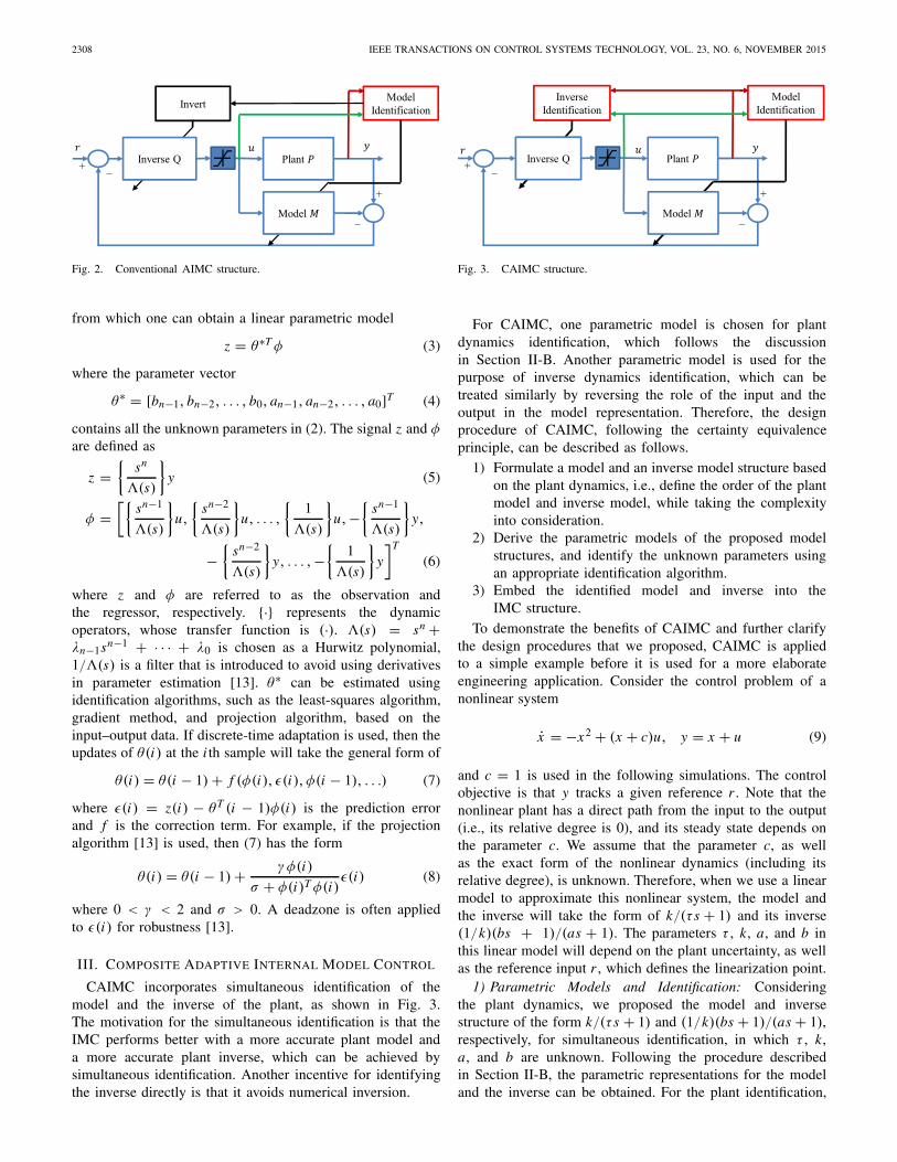
When there are uncertainties in the plants, AIMC com-bines identification with the IMC structure [5]. Most AIMCresults found in the literature are based on the certaintyequivalence principle, namely, the plant model was estimated,and then the estimated model M was treated as the true one,based on which the AIMC was designed. That is, Q wasdesigned as in Section II-A by finding an approximate inverseof the estimated M . The structure is shown in Fig. 2.
The identification of the plant can be performed with astandard parameter estimation approach. For nonlinear systemsthat can be approximated by a linear model at a givenoperating condition, an nth-order linear dynamic model canbe assumed to have the general form of [13]
y(n) + an−1 y(n−1) + · · · + a0 y
= bn−1u(n−1) + bn−2u(n−2) + · · · + b0u (2)
2308 IEEE TRANSACTIONS ON CONTROL SYSTEMS TECHNOLOGY, VOL. 23, NO. 6, NOVEMBER 2015
Fig. 2. Conventional AIMC structure.
from which one can obtain a linear parametric model
contains all the unknown parameters in (2). The signal z and φare defined as
z ={
sn
�(s)
}y (5)
φ =[{
sn−1
�(s)
}u,
{sn−2
�(s)
}u, . . . ,
{1
�(s)
}u,−
{sn−1
�(s)
}y,
−{
sn−2
�(s)
}y, . . . ,−
{1
�(s)
}y
]T
(6)
where z and φ are referred to as the observation andthe regressor, respectively. {·} represents the dynamicoperators, whose transfer function is (·). �(s) = sn +λn−1sn−1 + · · · + λ0 is chosen as a Hurwitz polynomial,1/�(s) is a filter that is introduced to avoid using derivativesin parameter estimation [13]. θ∗ can be estimated usingidentification algorithms, such as the least-squares algorithm,gradient method, and projection algorithm, based on theinput–output data. If discrete-time adaptation is used, then theupdates of θ(i) at the i th sample will take the general form of
where ε(i) = z(i) − θT (i − 1)φ(i) is the prediction errorand f is the correction term. For example, if the projectionalgorithm [13] is used, then (7) has the form
θ(i) = θ(i − 1) + γφ(i)
σ + φ(i)T φ(i)ε(i) (8)
where 0 < γ < 2 and σ > 0. A deadzone is often appliedto ε(i) for robustness [13].
III. COMPOSITE ADAPTIVE INTERNAL MODEL CONTROL
CAIMC incorporates simultaneous identification of themodel and the inverse of the plant, as shown in Fig. 3.The motivation for the simultaneous identification is that theIMC performs better with a more accurate plant model anda more accurate plant inverse, which can be achieved bysimultaneous identification. Another incentive for identifyingthe inverse directly is that it avoids numerical inversion.
Fig. 3. CAIMC structure.
For CAIMC, one parametric model is chosen for plantdynamics identification, which follows the discussionin Section II-B. Another parametric model is used for thepurpose of inverse dynamics identification, which can betreated similarly by reversing the role of the input and theoutput in the model representation. Therefore, the designprocedure of CAIMC, following the certainty equivalenceprinciple, can be described as follows.
1) Formulate a model and an inverse model structure basedon the plant dynamics, i.e., define the order of the plantmodel and inverse model, while taking the complexityinto consideration.
2) Derive the parametric models of the proposed modelstructures, and identify the unknown parameters usingan appropriate identification algorithm.
3) Embed the identified model and inverse into theIMC structure.
To demonstrate the benefits of CAIMC and further clarifythe design procedures that we proposed, CAIMC is appliedto a simple example before it is used for a more elaborateengineering application. Consider the control problem of anonlinear system
x = −x2 + (x + c)u, y = x + u (9)
and c = 1 is used in the following simulations. The controlobjective is that y tracks a given reference r . Note that thenonlinear plant has a direct path from the input to the output(i.e., its relative degree is 0), and its steady state depends onthe parameter c. We assume that the parameter c, as wellas the exact form of the nonlinear dynamics (including itsrelative degree), is unknown. Therefore, when we use a linearmodel to approximate this nonlinear system, the model andthe inverse will take the form of k/(τ s + 1) and its inverse(1/k)(bs + 1)/(as + 1). The parameters τ , k, a, and b inthis linear model will depend on the plant uncertainty, as wellas the reference input r , which defines the linearization point.
1) Parametric Models and Identification: Consideringthe plant dynamics, we proposed the model and inversestructure of the form k/(τ s + 1) and (1/k)(bs + 1)/(as + 1),respectively, for simultaneous identification, in which τ , k,a, and b are unknown. Following the procedure describedin Section II-B, the parametric representations for the modeland the inverse can be obtained. For the plant identification,
QIU et al.: CAIMC AND ITS APPLICATION TO BOOST PRESSURE CONTROL OF A TURBOCHARGED GASOLINE ENGINE 2309
TABLE I
PARAMETERS FOR TOY PROBLEM SIMULATION
the parametric model and the associated signals are defined as
z1 = θ∗T1 φ1
z1 ={
1
�1(s)
}y, θ∗
1 = [τ, k]T (10)
φ1 =[−
{s
�1(s)
}y,
{1
�1(s)
}u
]T
�1(s) = s + λ1.
For the inverse identification, the parametric model and theassociated signals are defined as
z2 = θ∗T2 φ2
z2 ={
1
�2(s)
}u, θ∗
2 =[
b
k,
1
k, a
]T
(11)
φ2 =[{
s
�2(s)
}y,
{1
�2(s)
}y −
{s
�2(s)
}u
]T
�2(s) = s + λ2
where λ1 and λ2 are the filter parameters. With the discrete-time projection algorithm (8), the unknown parameters can beidentified.
2) IMC Result: Two AIMC schemes are implementedand compared. One is the conventional AIMC as in Fig. 2designed with the certainty equivalence principle, where theplant is identified and the inverse is calculated based onthe identified model using the frozen parameter approach.A low-pass filter whose time constant is represented byτi is added to the inverse to assure causality. The other isCAIMC, where the plant dynamics and inverse dynamics areidentified simultaneously and no online calculation is involvedfor model inversion. The projection algorithm in (8) withdeadzone is adopted for parameter estimation of θ∗
1 and θ∗2
for its simplicity and robustness. Based on property 1) inSection II-A, zero steady-state tracking can be achievedby keeping a consistent k in the plant and inverse models.We simply used the estimated k in θ1 in both the modeland the inverse. The parameters used in the simulation aresummarized in Table I.
A square wave of amplitude 0.5 and period 18 s is usedfor the reference r . A white noise measurement of 3% isadded to the input and output measurements in all simulations.The simulation results are shown in Fig. 4 for a time intervalof [142, 178] s. Several conventional AIMC results are shownwith different τi . Before 142 s, the parameters have notconverged yet. One can observe that CAIMC and AIMCbased on the first-order linear model can handle the nonlinearplant, even with a different relative degree. Moreover,CAIMC achieves the performance that is as good as thatis achieved with AIMC, without the need to tune the filterparameter τi .
Fig. 4. Comparison of CAIMC and conventional AIMC for the toyproblem (9).
Nowadays, gasoline engines are aggressively downsized forfuel economy. To meet the customer demand for engine poweron the downsized engine, turbochargers are adopted to increasethe density of the air, thereby increasing the engine power.Boost control is a critical technology to fully exploit theadvantage of the turbocharged gasoline engine.
Fig. 5 shows the schematic of a turbocharged gasolineengine. The compressor and the turbine are connected througha mechanical link. Air is taken in by the compressor, goesthrough the cooler and throttle, and then it is pushed into thecylinders. The exhaust has two outlets: the turbine and the
2310 IEEE TRANSACTIONS ON CONTROL SYSTEMS TECHNOLOGY, VOL. 23, NO. 6, NOVEMBER 2015
Fig. 6. Simplified first-order model structure [15].
Fig. 7. Plant and inverse dynamic models. (a) First-order plant-modelstructure for identification. (b) First-order inverse-model structure foridentification.
pathway controlled by a wastegate. By changing the wastegateopening, the turbo airflow can be changed, which affects theturbo/compressor speed and changes the boost pressure. Theboost control problem is to use the wastegate as the actuatorto control the boost pressure to its reference. A physics-basedhigh-order nonlinear proprietary turbocharged gasoline enginemodel serves as the plant in the following design.
This application is motivated by the successful industrialapplications of IMC and the need for developing robustand easy-to-calibrate powertrain control solutions. Theturbocharged gasoline engine is a high-order nonlinearsystem, which operates in different environments. By addingidentification, the AIMC structure can handle the uncertaintiesincluding the unmodeled dynamics and the varying operatingenvironments. The direct identification of the inverse dynamicsin CAIMC will allow a better approximation of the inverse ofthe plant, making it attractive for the boost-pressure controlproblem.
A. Plant and Inverse Dynamic Models
CAIMC involves plant dynamics and inverse dynamics iden-tification, whose first step is to find feasible model and inversestructures to capture these dynamics. To sufficiently describethe air dynamics of a turbocharged gasoline engine, a fourth-order nonlinear first principle model is often derived [4].Karnik and Jankovic [15] simplified the fourth-order nonlinearmodel into a model as shown in Fig. 6. It includes a steady-state mapping from the wastegate uw to the turbo speed Nt , afirst-order linear model whose time constant is gain scheduled,and a compressor mapping. This structure motivates us tofurther simplify and propose a model structure as in Fig. 7(a),which combines the two mappings into a steady-state mappingfrom the wastegate uw to the boost pressure Pb and eliminatesthe intermediate variable of the turbo speed Nt . The corre-sponding plant inverse model structure is shown in Fig. 7(b).
B. Plant and Inverse Model Identification
Following the procedure outlined in Section II-B, theparametric models for the plant and the inverse dynamicsare obtained. Let u = Pb,ss and y = Pb . For the plantidentification, the parametric model is z1 = θ∗T
1 φ1 withthe same structure as (10). For the inverse dynamic modelidentification, the parametric model is z2 = θ∗T
2 φ2 with the
Fig. 8. Mapping accuracy. (a) From uw to Pb. (b) From Pb to uw .Black line represents exact fit. In (a), red line represents ±5% error. In (b),red line represents ±0.1 error.
Fig. 9. Turbocharged gasoline engine model identification.
same structure as (11). The identification algorithm used hereis the projection algorithm with deadzone, chosen for itssimplicity and robustness.
C. Derivation of the Static Maps
The model and inverse structures in Fig. 7(a) and (b)require a steady-state mapping between Pb and uw. As thethrottle opening and the engine speed change, this mappingchanges. A significant variable that affects the mapping is theengine airflow, because the engine airflow and uw determinethe turbo airflow, which determines the turbo/compressorspeed, therefore affecting Pb significantly. We formulate alookup table that depends on the engine airflow betweenthe steady-state values of Pb and uw . For wastegate uw,0 means open and 1 means closed. The accuracy of themapping by the lookup table is shown in Fig. 8(a) and (b).As shown in Fig. 8(a), mapping from uw to Pb is mostly within±5% error. As shown in Fig. 8(b), mapping from Pb to uw
is mostly within ±0.1. A gain k is added to the model andinverse structure in Fig. 7(a) and (b) to compensate for themapping inaccuracy.
D. Simulation Results
With the discrete-time projection algorithm and the staticmaps, which are derived offline, the plant and the inversedynamics are identified. Fig. 9 shows a comparison of theresponses of the plant, which is a high-order Ford proprietary
QIU et al.: CAIMC AND ITS APPLICATION TO BOOST PRESSURE CONTROL OF A TURBOCHARGED GASOLINE ENGINE 2311
model, and the identified first-order model. One can observethat the two responses are very close. An inverse model can bederived by inverting this model. To validate the inverse model,we feed a reference input to the inverse, whose output thenfeeds into the plant. This validation is performed for both theinverse model derived from the estimated plant model and theone identified directly. Fig. 10 shows the results. The identifiedinverse performs as well as the best derived inverse in termsof approximating the plant inverse. Although steady-state errorexists in both the plant and inverse identification results dueto mapping inaccuracy, the steady-state tracking problem canbe easily tackled in the IMC structure based on property 1)in Section II-A, by keeping a consistent k in the plant andinverse models. We simply used the estimated k in θ∗
1 inboth the model and the inverse. This paper verifies that thefirst-order model and inverse structures in Fig. 7(a) and (b) arefeasible for representing the plant and its inverse dynamics.
Fig. 11 shows the implementation schematic of the CAIMC,where the first-order model and inverse model structures givenin Fig. 7(a) and (b) are incorporated. Two AIMC schemes areimplemented and compared: 1) CAIMC as shown in Fig. 11and 2) the conventional AIMC as shown in Fig. 2, in whichthe model structure is as in Fig. 7(a). The parameters used insimulations are summarized in Table II. In conventionalAIMC, the time constant of the filter that is appended tothe inverse is carefully tuned to achieve the best perfor-mance. For CAIMC, however, such a tuning is not needed.The CAIMC results are shown in Fig. 12, while the
Fig. 11. CAIMC structure with the proposed model and inverse for theturbocharged gasoline engine.
TABLE II
PARAMETERS OF THE TURBOCHARGED GASOLINE
ENGINE MODEL SIMULATION
Fig. 12. CAIMC simulation result for the turbocharged gasoline engine.
conventional AIMC results are shown in Fig. 13, in whichseveral results are shown with different τi . One can observethat the performance of CAIMC matches the best performance
2312 IEEE TRANSACTIONS ON CONTROL SYSTEMS TECHNOLOGY, VOL. 23, NO. 6, NOVEMBER 2015
Fig. 13. Conventional AIMC simulation result for the turbocharged gasolineengine.
Fig. 14. CAIMC structure with the proposed model and inverse for theturbocharged gasoline engine in-vehicle testing.
of AIMC, thereby demonstrating the auto-tuning capabilityof the proposed CAIMC. Note that the parameters havenot converged yet before 2 s in Fig. 9 and before 4 sin Figs. 10, 12, and 13.
V. VEHICLE EXPERIMENTAL VALIDATION
The experiments were performed on a vehicle(Ford Explorer EcoBoost) with a turbocharged four-cylinder2-L gasoline engine with vacuum-actuated wastegate. Thevacuum in the wastegate canister determines the position ofthe wastegate. In this case, lower vacuum corresponds to moreopen wastegate and higher vacuum to more closed wastegate.The control objective is to use the wastegate canister vacuumas the actuator to control the boost pressure Pb to follow itsreference. The schematic of the strategy is shown in Fig. 14,which is very similar to the control structure for the computersimulation in Fig. 11, except that the actuator is the wastegatecanister vacuum Pv instead of the wastegate position. Note thatthe dynamics from Pv to the wastegate position are very
Fig. 15. Rapid control prototyping process.
fast, therefore it is reasonable to keep the first-order modeland inverse structure proposed in Fig. 7. To accommodatethe actuator of wastegate canister vacuum Pv , the model Mincludes a mapping from Pv to the boost pressure Pb, andthe inverse Q includes a mapping from Pb to Pv . Bothmappings were analyzed and shown to be within ±8% error.The parametric models for identification are exactly the sameas those used in Section IV for the design in (10) and (11).
A. Experimental Setup and Validation Approach
For experiments, the rapid control prototyping tools asin Fig. 15 were adopted: the boost control strategy was codedin MATLAB/Simulink,1 and then compiled and executed inreal time on the hardware platform dSPACE.2 dSPACE cancommunicate with powertrain control module of the vehicle toaccess vehicle data and command wastegate canister vacuum.The boost control strategy was executed at a sample timeof 15 ms. Both the boost pressure and the wastegate canisterpressure were measured by pressure sensors. An accurateestimation of the engine airflow was accessible. Theidentifications of M and Q were simultaneously performedonline. The identified parameters τ , k, a, and b in M and Qwere updated at each sample time.
Three different control algorithms were tested:1) the baseline controller: a well-tuned PI controller with
antiwindup and extensive gain-scheduled feedforwardand feedback control;
2) CAIMC as shown in Fig. 14;3) the conventional AIMC as shown in Fig. 2 with a well-
tuned time constant of the filter that is appended to theinverse.
The experiments were performed by driving the vehicleon the Ford test track in Dearborn, Michigan. Due to thedifference in the driver behavior, the operating points andboost pressure references vary for each test, which presentschallenges for test repeatability. To minimize the variation,we designed the following test procedure.
1) Start from a low vehicle speed and press the gas pedalto the ground such that the throttle is wide open.
2) Maintain the vehicle speed at 45 mi/h and enable thecruise control that sets the vehicle speed at 70 mi/h.
3) Repeat the last two steps.
B. Experimental Results
With the experimental setup and test procedure proposed,the results of different control algorithms are presentedand compared. For the baseline controller, when the airflow is
1MATLAB and Simulink are registered trademarks of The MathWorks, Inc.2dSPACE is a registered trademark of dSPACE GmbH.
QIU et al.: CAIMC AND ITS APPLICATION TO BOOST PRESSURE CONTROL OF A TURBOCHARGED GASOLINE ENGINE 2313
low, the default vacuum is 40.6 kPa. To make a fair compar-ison, the same default vacuum is applied to the other controlalgorithms. For CAIMC and conventional AIMC vehicletesting, the parameters are given in Table III. The sameparameters and initial conditions are used in CAIMC andconventional AIMC whenever applicable.
Figs. 16–18 show the vehicle testing results of the baselinecontroller, CAIMC, and a well-tuned AIMC controller,respectively. For all the tests, there were a portion whenthe throttle is wide open (90–100 s in Fig. 16, 105–115 sin Fig. 17, and 105–115 s in Fig. 18) and another portionwhen the vehicle is running in cruise control (130–160 sin Fig. 16, 145–175 s in Fig. 17, and 145–175 sin Fig. 18).
All the tests have comparable results; however, the baseline(Fig. 16) is achieved with sophisticated gain scheduling andextensive calibration. The conventional AIMC (Fig. 18) isachieved with the filter parameter that is tuned on the sim-ulation model, and then retuned on the vehicle. The CAIMC(Fig. 17) achieved the performance without any vehicle tuning.To show the effect of adaptation, the performance of
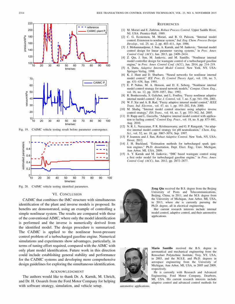
the system before parameter convergence was also evaluatedas in Fig. 19.
The identified parameters are shown in Fig. 20. The para-meters have not converged for 40 s, which explains the badcontrol performance before 40 s and demonstrates the benefitsof adaptation.
2314 IEEE TRANSACTIONS ON CONTROL SYSTEMS TECHNOLOGY, VOL. 23, NO. 6, NOVEMBER 2015
Fig. 19. CAIMC vehicle testing result before parameter convergence.
CAIMC that combines the IMC structure with simultaneousidentification of the plant and inverse models is proposed. Itsbenefits are demonstrated, using an example of controlling asimple nonlinear system. The results are compared with thoseof the conventional AIMC, where only the model identificationis performed and the inverse is numerically derived fromthe identified model. The design procedure is summarized.The CAIMC is applied to the nonlinear boost-pressurecontrol problem of a turbocharged gasoline engine. Numericalsimulations and experiments show advantages, particularly, interms of tuning effort required, compared with the AIMC withonly plant model identification. Future work in this directioncould include establishing general stability and performancefor the CAIMC systems and developing more comprehensivedesign guidelines for exploring the simultaneous identification.
ACKNOWLEDGMENT
The authors would like to thank Dr. A. Karnik, M. Uhrich,and Dr. H. Ossareh from the Ford Motor Company for helpingwith software strategy, simulation, and vehicle setup.
REFERENCES
[1] M. Morari and E. Zafiriou, Robust Process Control. Upper Saddle River,NJ, USA: Prentice-Hall, 1989.
[2] C. G. Economou, M. Morari, and B. O. Palsson, “Internal modelcontrol: Extension to nonlinear system,” Ind. Eng. Chem. Process DesignDevelop., vol. 25, no. 2, pp. 403–411, Apr. 1986.
[3] J. Mohammadpour, J. Sun, A. Karnik, and M. Jankovic, “Internal modelcontrol design for linear parameter varying systems,” in Proc. Amer.Control Conf. (ACC), Jun. 2013, pp. 2409–2414.
[4] Z. Qiu, J. Sun, M. Jankovic, and M. Santillo, “Nonlinear internalmodel controller design for wastegate control of a turbocharged gasolineengine,” in Proc. Amer. Control Conf. (ACC), Jun. 2014, pp. 214–219.
[5] A. Datta, Adaptive Internal Model Control. New York, NY, USA:Springer-Verlag, 1998.
[6] K. J. Hunt and D. Sbarbaro, “Neural networks for nonlinear internalmodel control,” IEE Proc. D, Control Theory Appl., vol. 138, no. 5,pp. 431–438, Sep. 1991.
[7] E. P. Nahas, M. A. Henson, and D. E. Seborg, “Nonlinear internalmodel control strategy for neural network models,” Comput. Chem. Eng.,vol. 16, no. 12, pp. 1039–1057, Dec. 1992.
[8] R. Boukezzoula, S. Galichet, and L. Foulloy, “Fuzzy nonlinear adaptiveinternal model control,” Eur. J. Control, vol. 7, no. 5, pp. 541–556, 2001.
[9] W. F. Xie and A. B. Rad, “Fuzzy adaptive internal model control,” IEEETrans. Ind. Electron., vol. 47, no. 1, pp. 193–202, Feb. 2000.
[10] M. Shafiq, “Internal model control structure using adaptive inversecontrol strategy,” ISA Trans., vol. 44, no. 3, pp. 353–362, Jul. 2005.
[11] D. Rupp and L. Guzzella, “Adaptive internal model control with applica-tion to fueling control,” Control Eng. Pract., vol. 18, no. 8, pp. 873–881,Aug. 2010.
[12] N. R. L. Narayanan, P. R. Krishnaswamy, and G. P. Rangaiah, “An adap-tive internal model control strategy for pH neutralization,” Chem. Eng.Sci., vol. 52, no. 18, pp. 3067–3074, Sep. 1997.
[13] P. Ioannou and J. Sun, Robust Adaptive Control. New York, NY, USA:Dover, 2012.
[14] J. H. Buckland, “Estimation methods for turbocharged spark igni-tion engines,” Ph.D. dissertation, Dept. Elect. Eng., Univ. Michigan,Ann Arbor, MI, USA, 2009.
[15] A. Y. Karnik and M. Jankovic, “IMC based wastegate control usinga first order model for turbocharged gasoline engine,” in Proc. Amer.Control Conf. (ACC), Jun. 2012, pp. 2872–2877.
Zeng Qiu received the B.S. degree from the BeijingUniversity of Posts and Telecommunications,Beijing, China, in 2011, and the M.S. degree fromthe University of Michigan, Ann Arbor, MI, USA,in 2013, where she is currently pursuing thePh.D. degree, all in electrical engineering.
Her current research interests include internalmodel control, adaptive control, and their automotiveapplications.
Mario Santillo received the B.S. degree inaeronautical and mechanical engineering from theRensselaer Polytechnic Institute, Troy, NY, USA,in 2003, and the M.S.E. and Ph.D. degrees inaerospace engineering from the University ofMichigan, Ann Arbor, MI, USA, in 2005 and 2009,respectively.
He is currently with Research and AdvancedEngineering, Ford Motor Company, Dearborn,MI, USA. His current research interests includeadaptive control and advanced control methods for
automotive applications.
QIU et al.: CAIMC AND ITS APPLICATION TO BOOST PRESSURE CONTROL OF A TURBOCHARGED GASOLINE ENGINE 2315
Mrdjan Jankovic (F’04) received thebachelor’s degree from the University of Belgrade,Belgrade, Serbia, and the master’s and Ph.D. degreesfrom Washington University, St. Louis, MO, USA.
He held post-doctoral teaching and researchpositions with Washington University and theUniversity of California, Santa Barbara, CA, USA.He joined Ford Research, Dearborn, in 1995, wherehe is currently a Senior Technical Leader, overseeinga team involved in development of powertraincontrol technologies. He has co-authored one book,
four book chapters, and over 100 technical papers. He is a co-inventor of over50 U.S. patents, 17 of which are implemented in Ford products worldwide.
Dr. Jankovic was a recipient of the IEEE Control Systems TechnologyAward, two Ford Research Technical Achievement Awards, and three bestpaper awards from the IEEE, SAE, and AVEC. He served as an AssociateEditor of the IEEE TRANSACTIONS ON CONTROL SYSTEMS TECHNOLOGYand the Chair of several IEEE and SAE committees.
Jing Sun (F’04) received the B.S. and M.S. degreesfrom the University of Science and Technology ofChina, Hefei, China, in 1982 and 1984, respectively,and the Ph.D. degree from the University ofSouthern California, Los Angeles, CA, USA,in 1989.
She was an Assistant Professor with theDepartment of Electrical and Computer Engineering,Wayne State University, Detroit, MI, USA, from1989 to 1993. She joined the Ford ResearchLaboratory, Dearborn, MI, USA, in 1993, where
she was involved with the Department of Powertrain Control Systems. Afterspending almost 10 years in the industry, she came back to academia andjoined the faculty of the College of Engineering, University of Michigan,Ann Arbor, MI, USA, in 2003, where she is currently a Professor withthe Department of Naval Architecture and Marine Engineering and theDepartment of Electrical Engineering and Computer Science. She hasco-authored a textbook entitled Robust Adaptive Control, and holds37 U.S. patents. Her current research interests include system and controltheory and its applications to marine and automotive propulsion systems.
Prof. Sun is one of the three recipients of the 2003 IEEE Control SystemTechnology Award.