● Cat. No. 239E ・ 08-2014 High Pressure Gas Safety Law Industrial Safety and Health Law (JAPAN) Regulation for Boiler and Pressure Vessel Manufacture Licensing (CHINA) ASME U Stamp (USA) CE Mark (EU) Compliant with all major Regulations and Standards ACCUMULATOR ACCUMULATOR
Transcript
●Cat. No. 239E・08-2014
High Pressure Gas Safety Law
Industrial Safety and Health Law(JAPAN)
Regulation for Boiler and Pressure Vessel Manufacture Licensing (CHINA)
ASME U Stamp (USA)
CE Mark(EU)
Compliant with all major Regulations and Standards
ACCUMULATORACCUMULATOR
NOK Accumulators have proved very popular with a number of customers as they are highly reliable with a wide ranging lineup available that are supported by global top-class rubber materials, seals and processing techniques, were designed with the environment taken into consideration, and are ISO14000 compliant.
The accumulators utilize the compressibility of gas. Feature greater energy efficiency, safety, and less noise.
1
Summ
aryList of M
odel Codes and Dimensions
Accessories and PartsH
andling and Selection
1. Features and Structure of Accumulator ・・・・・・・・・・・・・・・・・・・・・・・・・・・・ 2
2. Use of Accumulator ・・・・・・・・・・・・・・・・・・・・・・・・・・・・・・・・・・・・・・・・・・・・・・・・・・・・・・・・・・・・・・・ 4
3. Type of Accumulator ・・・・・・・・・・・・・・・・・・・・・・・・・・・・・・・・・・・・・・・・・・・・・・・・・・・・・・・・・・・・・ 6
4. Selection Procedure of Accumulator ・・・・・・・・・・・・・・・・・・・・・・・・・・・・・・・・・ 8
5. Accumulator Lists of Maximum Working Pressures and Volumes ・・・ 9
6. NOK Accumulator Series Lists ・・・・・・・・・・・・・・・・・・・・・・・・・・・・・・・・・・・・・・・・・・ 10
NOK ACCUMULATORNOK ACCUMULATORNOK ACCUMULATORNOK ACCUMULATORNOK ACCUMULATORNOK ACCUMULATORNOK ACCUMULATORNOK ACCUMULATORNOK ACCUMULATOR
2
1. 1. Features and Structure of Accumulator
1. Features The accumulators utilize the compressibility of gas.Incorporating an accumulator with hydraulic equipment or other machinery that utilizes fluids can enable the accumulation of pressure which can then be used in momentarily supplying large volumes of fluid or absorbing pulses or impact pressure from pipes, while they can also play a significant role in improving the performance of equipment and machinery, including greater energy efficiency and less noise generation.The accumulators can be divided into being of the membrane or piston type, depending on how the nitrogen gas is separated from the fluid.
◆ The following shows the operating states and structure of a representative bladder type membrane accumulator:
dFill with nitrogen gas
h
Status before use[Contains neither nitrogen
gas nor fluid]
Filled with nitrogen gas
cg
Inflow
Fluid flows in
dh
Discharge
Required amount of fluid discharged
3
Summ
ary
TRキャップ
2. Structure(AT series)
バルブガードキャップガスバルブ 窒素ガス封入, 排出口
バルブステム ガスバルブ, ガスコントロールバルブ取付口
AER(アンチエキストリュージョンリング) ブラダ膨張時の保護
シェル 容器
ブラダ 窒素ガスと液体の分離
ポペット ブラダ膨張時の保護
AER(アンチエキストリュージョンリング) ブラダ膨張時の保護
オイルポート 液体の流出入口、配管接続部
TR Cap [Fusible-plug Safety Valve]A safety valve that senses an abnormally
high temperature. It can be attached to the gas valve as a replacement to the cap.
(*Can also be attached to a Minilator.)
Differing size bushings and flanges are available for use in connecting the accumulator to equipment and machinery.
ガスコントロールバルブ
Gas Control ValveThe valve integrates a filling port for the
nitrogen gas, a pressure gauge, and safety valve, and is attached to the valve stem.
(*Note that the valve stem differs from the gas valve.)
Valve GuardCapGas ValvePort for filling or discharging nitrogen gasValve StemPort for attaching a gas valve or gas control valveAER (Anti-Extrusion Ring)Bladder expansion protection
Oil PortInflow/outflow port for fluid and pipe connections
Gas Side Options
Bushing Flange
継手取付ネジ
Joint attachment thread
Joint attachment thread
O-ring O-ring
Bushing Flange
継手取付ネジ
Joint attachment thread
Joint attachment thread
O-ring O-ring
Joint for Fluid Port Connecting
FlangeBushing
See: pages 37~39
See: pages 32 ~35
TR cap Gas Control Valve
4
2.
P
t(℃)
P
2. Use of Accumulator
1. Energy AccumulationAccumulators are widely used as a supplementary energy source.The system in which pressurized oil discharged from accumulators is used to operate cylinders enables pumps to be smaller, shortens their cycles, and conserves energy.
2. Pulse AbsorptionAll pressurized fluid discharged from pumps has a pulse.Pulses produce noise or vibrations that can cause instability or damage devices.The use of an accumulator can attenuate pulses.
3. Impact AbsorptionThe rapid closure of valves or sudden changes in load within a hydraulic circuit can result in impact pressure in pipes, which can then lead to noise or damage to those pipes or devices.The use of an accumulator can mitigate any such internal shock.
4. Thermal Expansion CompensationChanges in the volume of a liquid resulting from changes in the temperature within a closed circuit can increase or decrease the internal pressure. An accumulator can be used to mitigate any such fluctuations in the pressure.
Small pumps
[Major Examples of Usage]Hydraulic pressesInjection molding machinesDie-cast machinesAutomotive brake systemsPower shovelsVibration testing machinesCircuit breakers for transformer substationsWater supply systemsHome pumpsEquipment for ironworks, power plants, and chemical plantsShip engines
Machine toolsBreakers for construction machineryConcrete compressorsHydraulic elevatorsPower sprayersWater purification plantsDescaling equipment
Water pipesJet fuel injection equipmentMud-water compressorsPipelines
BoilersPressurized water heatersCentral heating systemsFire extinguishing systems
Large pumps
W WWWW
W
5
Summ
ary
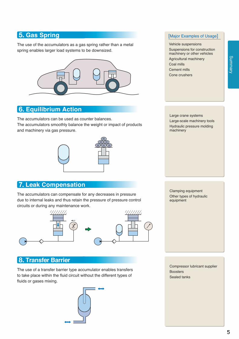
[Major Examples of Usage]Vehicle suspensionsSuspensions for construction machinery or other vehiclesAgricultural machineryCoal millsCement millsCone crushers
Large crane systemsLarge-scale machinery toolsHydraulic pressure molding machinery
Clamping equipmentOther types of hydraulic equipment
5. Gas SpringThe use of the accumulators as a gas spring rather than a metal spring enables larger load systems to be downsized.
6. Equilibrium ActionThe accumulators can be used as counter balances.The accumulators smoothly balance the weight or impact of products and machinery via gas pressure.
7. Leak CompensationThe accumulators can compensate for any decreases in pressure due to internal leaks and thus retain the pressure of pressure control circuits or during any maintenance work.
8. Transfer BarrierThe use of a transfer barrier type accumulator enables transfers to take place within the fluid circuit without the different types of fluids or gases mixing.
6
3. 3. Type of Accumulator
NOK has a wide variety of accumulators available that can satisfy the demands of differing applications and usage conditions.
Compact, small volume type Maintenance-free, small volume spherical typeMinilators Diaphragm type
MA seriesStainless-steel type ME series
Lightweight aluminum type
See: page12
MB seriesSteel type
MU seriesRubber diaphragm type
MUV series
Gas retention to at least 10 times that of single rubber typeMC series
Steel type
See: page14
See: page15
Rubber/resin layered diaphragm type
7
Replaceable bladders for subsequent use with larger productsBladder type
AL series
Bladder replaceable from the fluid side
Enables higher pressure and larger volume designsPiston type
PA series
Expansion tank
ET seriesAT series
Bladders may be replaced either from the gas or fluid side
Type A
Type B
Type C
See: page18
See: page20
See: page30
See: page31
Summ
ary
(NB) No further surface treatment beyond a basecoat applied to standard products.
Low-pressure type for use with water that is compliant with the Food Sanitation Law of Japan
8
4. 4. Selection Procedure of Accumulator
Use the following procedure to select the most appropriate accumulator:
1. Determine the application of the accumulatorDetermine the application of the accumulator from its intended use.
Examples of Intended Use:●Reducing the power supplied to a hydraulic press ・・・・・・・・・・・・・・・・・・・・・・・・・・・・・・・・・・・・・・・・・・・・・・・・・・・・・・・・・
●Instantaneous operation of a hydraulic cylinder ・・・・・・・・・・・・・・・・・・・・・・・・・・・・・・・・・・・・・・・・・・・・・・・・・・・・・・・・・・・・・・
●Preventing pump pulsations from damaging devices ・・・・・・・・・・・・・・・・・・・・・・・・・・・・・・・・・・・・・・・・・・・・・・・・・・・・・
●Preventing any damage to pipes when switching valves ・・・・・・・・・・・・・・・・・・・・・・・・・・・・・・・・・・・・・・・・・・・・・・
●Preventing any damage to devices when a closed circuit is at high temperature ・・・・・・・・
●Car and crane suspension systems ・・・・・・・・・・・・・・・・・・・・・・・・・・・・・・・・・・・・・・・・・・・・・・・・・・・・・・・・・・・・・・・・・・・・・・・・・・・・・・・・・・・・
●Small power operation of heavy objects ・・・・・・・・・・・・・・・・・・・・・・・・・・・・・・・・・・・・・・・・・・・・・・・・・・・・・・・・・・・・・・・・・・・・・・・・・・・・
●Preventing any loss in pressure due to leakage from valves while pumps are under suspension ・・・・・・●Compressing high-viscosity lubrication using hydraulic oil ・・・・・・・・・・・・・・・・・・・・・・・・・・・・・・・・・・・・・・・・・・・
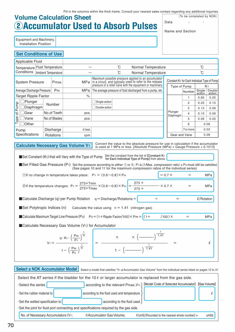
2. Calculate the required volume of gasCalculate the required volume of gas from the intended usage conditions.Example calculations and worksheets are available for use in calculating the relevant energy accumulation, pulsation absorption, and impact absorption.Please consult your nearest sales contact for any other purposes.
Please consult your nearest sales contact in advance in any case where you will require certification or application to follow any pertinent laws or standards.
●High Pressure Gas Safety Law (high pressure gas production equipment) ●Industrial Safety and Health Law (class-2 pressure vessel) ●ASME U Stamp (American Society of Mechanical Engineers) ●Regulation for Boiler and Pressure Vessel Manufacture Licensing (China) ●CE Marking (European Pressure Equipment Directive) ●OtherThe Product Codes for the AT series vary by applicable laws and standards.See pages 22 through 28.
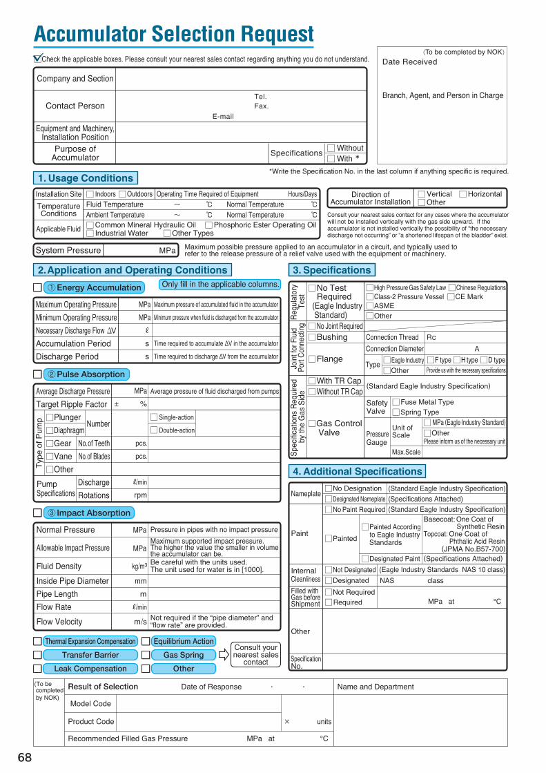
Fill in the Accumulator Selection Request (page 68) and we will select the most appropriate accumulator for you.
3. Select the most appropriate accumulatorAfter calculating the required volume of gas, set the following specifications to select the most appropriate accumulator. Specification Setting①Maximum Working Pressure ・・・・・・・・・・・・・・・・・・・・・・・・・・・ System pressure or greater②Volume of Gas ・・・・・・・・・・・・・・・・・・・・・・・・・・・・・・・・・・・・・・・・・・・・・・・・・・・・・ Calculated required volume of gas or greater③Rubber Material ・・・・・・・・・・・・・・・・・・・・・・・・・・・・・・・・・・・・・・・・・・・・・・・・・・・ Must comply with the fluid used and temperature conditions④Maximum Discharge Rate ・・・・・・・・・・・・・・・・・・・・・・・・・・・・・・・ Necessary rate or greater⑤Specification of Wet Part ・・・・・・・・・・・・・・・・・・・・・・・・・・・・・・・・・・ Must comply with the fluid used⑥Joint for Fluid Port Connecting ・・・・・・・・・・・・・・・・・・・・・・・ Kind and size ⑦Specifications Required by the Gas Side ・・・ Kind and size
page 4
page 58
pages 9 to 39
9
5. 5. Accumulator Lists of Maximum Working Pressures and VolumesSum
mary
Accumulator for Use in Japan
Series Nominal Volume
Maximum Working Pressure: MPa6.86 14.7 16 20.6 22.6 29.4 34.3
MAMBMCMEMUMUV
30㎝3 ME70-30
100 ME70-100 MB210-100
150 MUV70-150
300MA70-300
MB210-300ME70-300
MU70-300
500
MA70-500
MB210-500ME70-500
MUV70-500
MU70-500
700 MU150-700
1000 MC70-1000 MC210-1000
2000 MC70-2000 MC210-2000
3000 MC70-3000 MC210-3000
5000 MC70-5000 MC210-5000
ALATPA
1 R AL150-1 PA210-1 AL300-1
2 PA210-2
2.4 AL150-2.4 AL300-2.4
3 PA210-3
4 AL150-4 PA210-4 AL300-4
5 AL150-5 PA210-5 AL300-5
10 AT18M-10 PA210-10 AT25M-10 AT35M-10
20 AT18M-20 PA210-20 AT25M-20 AT35M-20
30 AT18M-30AT23M-30
AT25M-30 AT35M-30PA210-30
40AT23M-40
PA210-40
50 AT18M-50AT23M-50
AT25M-50PA210-50
60 AT23M-60
80 AT23M-80
120 AT23M-120
150 AT23M-150
160 AT23M-160
AT Series for Overseas Use
Series Nominal Volume
Maximum Working Pressure: MPa18 23 25 35
AT
10 R AT18M-10 AT25M-10 AT35M-10
20 AT18M-20 AT25M-20 AT35M-20
30 AT18M-30 AT23M-30 AT25M-30 AT35M-30
40 AT23M-40
50 AT18M-50 AT23M-50 AT25M-50
60 AT23M-60
80 AT23M-80
120 AT23M-120
150 AT23M-150
160 AT23M-160
Expansion Tank for Use in Japan
Series Nominal Volume
Maximum Working Pressure: MPa0.45 0.5 0.85 2.0
ET
0.5 R ET4.5-0.5
1 ET4.5-1
2 ET5-2
10 ET8.5-10
20 ET8.5-20 ET20-20
150
100 100 100 100 100 100 100 80 80 80
-20 -20 -20 -20 -20 -15 -30 -30 -40 -40 -40
10
6. 6. NOK Accumulator Series Lists
(°C) 100
0
*1: General mineral oil used at room temperature.*2: The specifications of the accumulators can vary depending on the type of fluid used. For more details please refer to the Model Code
Configurations of each individual series.*3: The pressure of the nitrogen gas in the accumulator can gradually drop as a result of it seeping through the rubber. Caution should be exercised with regard to maintenance as the pressure of the gas can drop faster at higher temperatures (see page 55).
NBR (Standard Nitrile Rubber)
NBR (Nitrile Rubber for Low Temperature Use)
IIR (Butyl Rubber)
FKM (Fluororubber)
CM (Chlorinated Polyethylene)
Consult your nearest sales contact if you wish to constantly use the product at high temperature.
Volume Category
Type of Accumulator
Series
Basic Specifi- cations
Maximum Discharge Flow(R/min)*1
*2Appli- cable Fluids
Applicable Temperature Range for Each Type of Rubber Material *3
Maximum Compression Ratio*5
Specifications of Joint for Fluid Port ConnectingSpecifi- cations required by the gas sideDirection Attached
Mainte- nance
Refer to the Model Code Dimensions and Product Code Page
— — — ○ ○ Vertical/Horizontal Restrictionless Vertical Vertical Restrictionless Supported Not Supported Supported Supported Supported Not Supported Supported Not Supported Not Supported Not Supported Replace from the fluid side
Page12 Page14 Page15 Page12 Page18 Page 30
Diaphragm type Minilators Bladder type Piston type
1〜 5 R
Model
Shape
Shell MaterialStandard Surface Treatment
(Unit)Nominal VolumeMaximum Working Pressure (MPa)
General Mineral OilPhosphate EsterIndustrial WaterWater GlycolPotable Water
TR Caps Included*5
Gas Control Valve Included
Gas Filling
Bladder and Seal Replacement
ゴムダイアフラム ゴム/樹脂積層ダイアフラム
Gas retention at least 10
times that of MU
Rubber Diaphragm
Rubber/Resin Layered
Diaphragm
Consult your nearest
sales contact
Consult your nearest
sales contact
11
[Meaning of symbols used] ◎ : Standard product (with Model Codes and Product Codes provided) ○ : No Product Code provided. Specify using Model Code. (○) : Consult your nearest sales contact.
150
100 100 100 80 80 85 85
-10 -10 -20 -20 -20 -15 -30 -40 -40
(°C) 100
0
*4: Compression Ratio: Ratio of maximum operating pressure (P3) to gas filling pressure (P1). [P3/P1] Convert the value to the absolute pressure for use in the calculation if the accumulator is used at 1 MPa or less. [Absolute Pressure (MPa) = Gauge Pressure + 0.1013]
*5: Not applicable if the ambient temperature always exceeds 80 °C.*6: The maximum working pressure and maximum discharge flow for the AT series can vary by individual model. See [AT Series] on pages 20 and 21 for more details.
Note that use of the product at a pressure exceeding the maximum compression ratio can shorten the useful lifespan of the bladder.
List of Model Codes and Dim
ensions
Volume Category
Type of Accumulator
Series
Basic Specifi- cations
Maximum Discharge Flow (R/min)*1
*2Appli- cable Fluids
Applicable Temperature Range
for Each Type of Rubber Material *3
Maximum Compression Ratio*5
Specifications of Joint for Fluid Port Connecting
Specifi- cations required by the gas side
Direction Attached
Mainte- nance
Refer to the Model Code Dimensions and Product Code Page
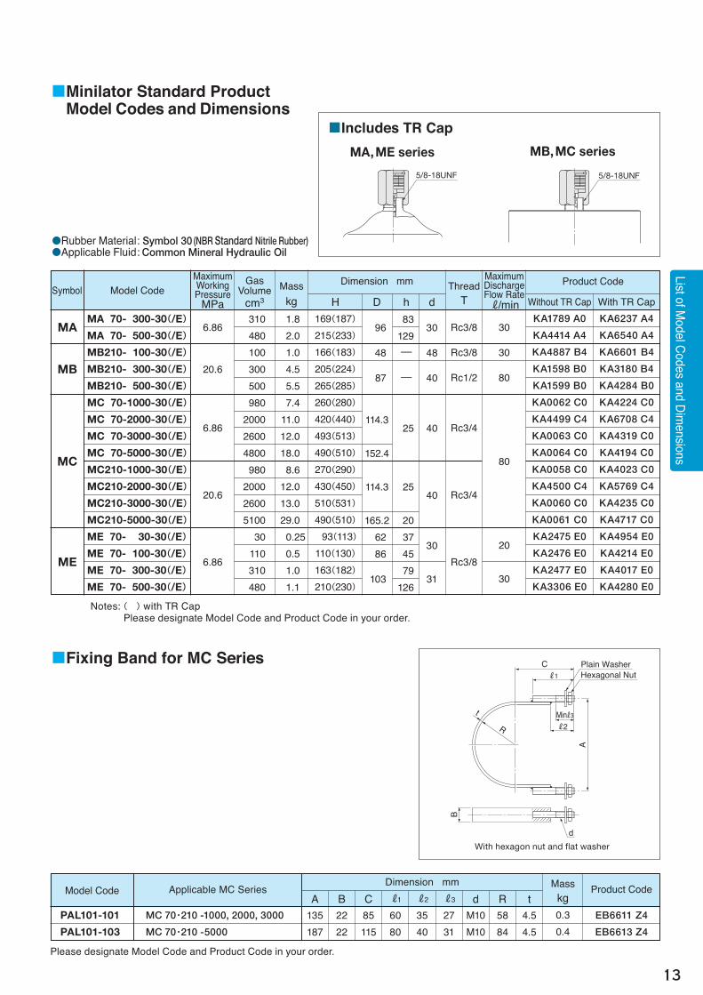
Notes: ( ) with TR Cap Please designate Model Code and Product Code in your order.
■Minilator Standard Product Model Codes and Dimensions
●Rubber Material: Symbol 30 (NBR Standard Nitrile Rubber)●Applicable Fluid: Common Mineral Hydraulic Oil
■Includes TR CapMA, ME series MB, MC series
5/8-18UNF 5/8-18UNF
Model Code Product CodeDimension mm
PAL101-101
PAL101-103
Applicable MC Series
MC 70・210 -1000, 2000, 3000
MC 70・210 -5000
Masskg0.30.4
A B C R1 R2 R3 d R t135187
2222
85115
6080
3540
2731
M10M10
5884
4.54.5
Please designate Model Code and Product Code in your order.
■Fixing Band for MC Series C
B
A
R
t
R1
MinR3R2
d
Plain Washer
With hexagon nut and flat washer
Hexagonal Nut
EB6611 Z4
EB6613 Z4
■Model Code Configuration
14
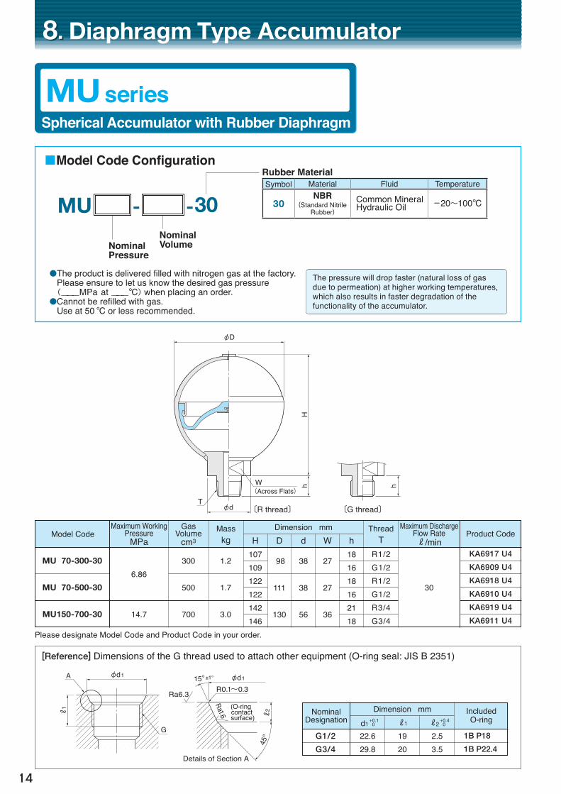
8. 8. Diaphragm Type Accumulator
MU seriesSpherical Accumulator with Rubber Diaphragm
Model Code Product Code
KA6917 U4
KA6909 U4
KA6918 U4
KA6910 U4
KA6919 U4
KA6911 U4
NominalVolumeNominal
Pressure
Rubber Material
●The product is delivered filled with nitrogen gas at the factory. Please ensure to let us know the desired gas pressure (___MPa at ___°C) when placing an order.●Cannot be refilled with gas. Use at 50 °C or less recommended.
Please designate Model Code and Product Code in your order.
[Reference] Dimensions of the G thread used to attach other equipment (O-ring seal: JIS B 2351)
φD
Hh hW
(Across Flats)
〔R thread〕 〔G thread〕T
φd
The pressure will drop faster (natural loss of gas due to permeation) at higher working temperatures, which also results in faster degradation of the functionality of the accumulator.
Nominal Designation
1B P18
1B P22.4
R1
R2
A
R0.1~0.3
Details of Section A
Ra6.3
G
φd1 φd115° ±1°
45°
Ra1.6 R2(O-ring
contact surface)
6.86
14.7
300
500
700
Maximum WorkingPressure
MPaDimension mm
MU 70-300-30
MU 70-500-30
MU150-700-30
Gas Volume
cm3
1.2
1.7
3.0
Masskg
R1/2G1/2R1/2G1/2R3/4G3/4
ThreadTH
107109122122142146
D
98
111
130
d
38
38
56
W
27
27
36
h181618162118
30
Maximum Discharge Flow RateR/min
- -MU 30
Dimension mm
G1/2
G3/4
Included O-ringd1
+0.10 R1 R2
+0.40
22.629.8
1920
2.53.5
Symbol Material Fluid Temperature
30NBR
(Standard Nitrile Rubber)
Common MineralHydraulic Oil -20〜100°C
15
List of Model Codes and Dim
ensions
NominalVolumeNominal
Pressure
Rubber Material
[Reference] Dimensions of the G thread used to attach other equipment (O-ring seal: JIS B 2351)
■Model Code Configuration
MUV seriesSpherical Accumulator with Rubber/Resin Layered Diaphragm Long-life type retaining at least 10 times as much gas as the MU type
Model Code Product Code
KA6912 U4
KA6949 U4
KA6914 U4
KA6951 U4
●The product is delivered filled with nitrogen gas at the factory. Please ensure to let us know the desired gas pressure (___MPa at ___°C) when placing an order.●Cannot be refilled with gas. Use at 80 °C or less recommended.
Please designate Model Code and Product Code in your order.
Resin MembraneRubber Layer
φDH
h hW(Hex.)
T
Sectional View of Layered Diaphragm
〔R thread〕 〔G thread〕
R1
R2
A
R0.1~0.3
Details of Section A
Ra6.3
G
φd1 φd115° ±1°
45°
Ra1.6 R2(O-ring
contact surface)
Nominal Designation
Dimension mm
G3/8
G3/4
Included O-ring
1B P14
1B P22.4
d1 +0.1
0 R1 R2 +0.4
0
18.629.8
1620
2.53.5
Use of NOKʼs polymeric material technology and processing technology has resulted in a resin layered diaphragm that dramatically improves the gas retention of accumulators. This accumulator should be selected if a longer lifespan and maintenance-free operation are desired.
Symbol Material Fluid Temperature
30NBR
(Standard Nitrile Rubber)
Common MineralHydraulic Oil -20〜100°C
Maximum WorkingPressure
MPa
6.86
150
500
Dimension mm
MUV70-150-30
MUV70-500-30
Gas Volume
cm3
0.7
2.5
Masskg
R3/8G3/8R3/4G3/4
ThreadT
93
117
86
128
30
36
14
18
H D W h
10
30
Maximum Discharge Flow RateR/min
- -MUV 30
■Model Code Configuration
16
9. 9. Bladder Type Accumulator
:Basic Model Code
Inner Surface of Shell
Retainer Ring (For AER)
Oil Port Body Assembly
- - /-
③�Nominal Volume
②�Nominal Pressure
④Rubber Material
⑧FluidFluid Contact Metal Parts Specification
(See the left picture.)
⑥Specifications Required by the Gas Side
⑦Gas Control Valve Types ⑤Joint for Fluid Port Connecting
(Note) The maximum working temperature of the epoxy coated type is 40 °C.
①Series
【Fluid Contact】Metal Parts
シェル内面
リテーナーリング(AER用)
オイルポートボディアッセンブリ
⑨Type of Oil Port Body Assembly
Symbol Maximum Discharge Flow Rate(R/min)AL1, 2.4 R AL4, 5 R AT10〜60 R AT80〜160 R
* The Product Codes for the AT series vary by applicable laws and standards. See pages 22 through 28.
Symbol
None
W
Fluid
Common Mineral Hydraulic OilPhosphoric Ester Hydraulic Oil
Industrial Water
Parkerizing(Standard)
Epoxy(Note)
Coating Stainless Steel
Inner Surface of Shell
Retainer Ring
(For AER)
Oil Port Body
Assembly
SymbolALAT
Symbol Material Fluid Temperature Note
30NBR
(Standard Nitrile Rubber)
Common MineralHydraulic Oil,Industrial Water,Water Glycol
-20〜100°C StandardMaterial
10NBR
(Nitrile Rubber for Low Temperature Use)
Common MineralHydraulic Oil -40〜80°C
Material For Low
Temperature
40 I IR(Butyl Rubber)
Phosphoric EsterHydraulic Oil -30〜100°C (Note)
(Note) Because this material cannot be applied in some kinds of phosphoric ester hydraulic oil, please consult your nearest sales contact.
Symbol Specification PageNone — —
E TR Cap Page 37 (Note)
M Fuse Metal Safety Valve Page 39
GF06 Gas Port Flange used as Transfer Barrier Page 29
(Note) In case of ambient temperature always exceeding 80°C, TR Cap cannot be used.
Symbol Specification PageNone Standard Type —
GC With Gas ControlValve Types Page 38
Symbol Specification PageNone No Connecting Part —
T** Bushing Page 32F** 21 MPa Flange Set Page 33H** 35 MPa Flange Set Page 34D** Manifold Direct Assembly Type Page 35
Standard Material: SteelFor Industrial Water: Stainless Steel
Model Code Specification
AT 25M -10 -30/T06 E ① ② ③ ④ ⑤ ⑥
17
■Example of Model Code Configuration
AT 25M -10 -30 ① ② ③ ④
AT 25M -10 -30/T06 ① ② ③ ④ ⑤
AT 25M -10 GC - 30/F06 ① ② ③ ⑦ ④ ⑤
AT 25M -10 GC - 30/W T06 M ① ② ③ ⑦ ④ ⑧ ⑤ ⑥
AT 25M -10 GC -30-HF/WF16 M ① ② ③ ⑦ ④ ⑨ ⑧ ⑤ ⑥
① AT Series② Maximum Working Pressure: 22.6 MPa
(Japanese Model Specifications)③ Nominal Volume: 10 R④ Rubber Material : NBR(Standard Nitrile Rubber)
① AT Series② Maximum Working Pressure: 22.6 MPa
(Japanese Model Specifications)③ Nominal Volume: 10 R④ Rubber Material : NBR(Standard Nitrile Rubber)⑤ Joint: Bushing Rc3/4
① AT Series② Maximum Working Pressure: 22.6 MPa
(Japanese Model Specifications)③ Nominal Volume: 10 R④ Rubber Material : NBR(Standard Nitrile Rubber)⑤ Joint: Bushing Rc3/4⑥ With TR Cap
① AT Series② Maximum Working Pressure: 22.6 MPa
(Japanese Model Specifications)③ Nominal Volume: 10 R④ Rubber Material : NBR(Standard Nitrile Rubber)⑤ Joint: F Type Flange: 25 A⑦ With Gas Control Valve Types Spring Safety Valve as the Code Is Not Followed by an M (See page 38 for the Model Code Configuration of GC models.)
① AT Series② Maximum Working Pressure: 22.6 MPa
(Japanese Model Specifications)③ Nominal Volume: 10 R④ Rubber Material : NBR(Standard Nitrile Rubber)⑤ Joint: Bushing Rc3/4⑥ Fuse Metal Safety Valve when Combined with GC(M)⑦ With GC ⑧ For Water Service (Inner Surface of Shell: Epoxy Coating, Fluid Contact Metal Parts: Stainless Steel)
① AT Series② Maximum Working Pressure: 22.6M Pa
(Japanese Model Specifications)③ Nominal Volume: 10 R④ Rubber Material : NBR(Standard Nitrile Rubber)⑤ Joint: F Type Flange 50 A⑥ Fuse Metal Safety Valve when Combined with GC⑦ With GC ⑧ For Water Service⑨ High Flow, Maximum Discharge Flow Rate 1800 R/min
List of Model Codes and Dim
ensions
■With TR CAP AL1, 2.4 AL4, 5
18
AL□-1, 2.4 AL□-4, 5
■Basic Model
-ALNominalVolumeNominal
Pressure
14.729.414.729.414.729.414.729.4
1.0
2.5
3.7
5.2
1
2.4
4
5
NominalVolume
RBasic Model
Dimension mm
AL150 - 1
AL300 - 1
AL150 - 2.4
AL300 - 2.4
AL150 - 4
AL300 - 4
AL150 - 5
AL300 - 5
Gas Volume
R
126
370
Maximum Discharge Flow RateR/min
Maximum WorkingPressure
MPa
7.6
13.6
14.3 20.3 18.3 26.3
H (Note)
282(290)
487(495)
404(418)
405(419)
495(509)
496(510)
Masskg D
120.0
120.0
168.3 177.8 168.3 177.8
N 51
51
79 78 79 78
Note: Values in brackets represent the dimensions with a TR cap attached.
Hex. 30
Hex. 32
40HφD
20N
Across Flats 52φ56φ82
Rc 3/4(PT)
G1 1/4
AN6227 #27
Hex. 30
Hex. 32 61H
24N
Hex. 21
Hex. 26 35HφD
14N
Across Flats 32φ35.6φ49
G3/4
Rc3/8(PT)
JIS B 2401 P22
Across Flats 71φ76φ100
G 2
φD
AL series (1, 2.4, 4, 5 R)
Bladder Type Accumulator with the Bladder Replaceable from the Fluid Side
H Type Flange 20A /H06 KY5017 □0 /H06E KY7017 □0Please designate Model Code and Product Code in your order. *Select K (high pressure gas) or S (in-house inspection) with regard to □ of the Product Code.
(1)Example “Model Code” Confi guration
■Standard Product: List of Model Codes and Product CodesAT series Standard Flow Rate Models:10, 20 RNominalVolume
R
Maximum WorkingPressure
MPa
Joint for Fluid Port
ConnectingSize
Without TR CAP With TR CAP
Model Code Product Code * Model Code Product Code *
D Type Flange 50A /D16 KY5056 □0 /D16E KY7056 □0Please designate Model Code and Product Code in your order. *Select K (high pressure gas) or S (in-house inspection) with regard to □ of the Product Code.
■Standard Product: List of Model Codes and Product CodesAT series Standard Flow Rate Models: 30, 40, 50, 60 RNominalVolume
R
Maximum WorkingPressure
MPa
Joint for Fluid Port
ConnectingSize
Without TR CAP With TR CAP
Model Code Product Code * Model Code Product Code *
F Type Flange 20A /F06 KY5044 □0 /F06E KY7044 □0Please designate Model Code and Product Code in your order. *Select K (high pressure gas) or S (in-house inspection) with regard to □ of the Product Code.
Japanese Regulations Japanese Regulations Japanese Regulations Compliant ProductsCompliant ProductsCompliant Products
Japanese Regulations Compliant Products
Japanese Regulations Japanese Regulations Japanese Regulations Compliant Products
Japanese Regulations Compliant Products
Japanese Regulations Compliant Products
Japanese Regulations Japanese Regulations Japanese Regulations Compliant Products
Japanese Regulations
●Rubber Material: Symbol 30 (NBR Standard Nitrile Rubber)●Applicable Fluid: Common Mineral Hydraulic Oil
●Rubber Material: Symbol 30 (NBR Standard Nitrile Rubber)●Applicable Fluid: Common Mineral Hydraulic Oil
24
AT series Middle High Flow(MH)TypeNominalVolume
R
Maximum WorkingPressure
MPa
Joint for Fluid Port
ConnectingSize
Without TR CAP With TR CAP
Model Code Product Code * Model Code Product Code *
20F Type Flange AT25M-20-30-MH/F20 KY5084 □0 AT25M-20-30-MH/F20E KY7084 □0D Type Flange /D20 KY5085 □0 /D20E KY7085 □0
30F Type Flange AT25M-30-30-MH/F20 KY5086 □0 AT25M-30-30-MH/F20E KY7086 □0D Type Flange /D20 KY5087 □0 /D20E KY7087 □0
40 20.6 F Type Flange AT23M-40-30-MH/F20 KY5088 □0 AT23M-40-30-MH/F20E KY7088 □0D Type Flange /D20 KY5089 □0 /D20E KY7089 □0
50 22.6 F Type Flange AT25M-50-30-MH/F20 KY5090 □0 AT25M-50-30-MH/F20E KY7090 □0D Type Flange /D20 KY5091 □0 /D20E KY7091 □0
80
20.6
F Type Flange AT23M-80-30-MH/F20 KY5092 □0 AT23M-80-30-MH/F20E KY7092 □0D Type Flange /D20 KY5093 □0 /D20E KY7093 □0
120F Type Flange AT23M-120-30-MH/F20 KY5094 □0 AT23M-120-30-MH/F20E KY7094 □0D Type Flange /D20 KY5095 □0 /D20E KY7095 □0
150F Type Flange AT23M-150-30-MH/F20 KY5096 □0 AT23M-150-30-MH/F20E KY7096 □0D Type Flange /D20 KY5097 □0 /D20E KY7097 □0
160F Type Flange AT23M-160-30-MH/F20 KY5098 □0 AT23M-160-30-MH/F20E KY7098 □0D Type Flange /D20 KY5099 □0 /D20E KY7099 □0
Please designate Model Code and Product Code in your order. *Select K (high pressure gas) or S (in-house inspection) with regard to □ of the Product Code.
■Standard Product: List of Model Codes and Product CodesAT series Semi High Flow(SH)TypeNominalVolume
R
Maximum WorkingPressure
MPa
Joint for Fluid Port
ConnectingSize
Without TR CAP With TR CAP
Model Code Product Code * Model Code Product Code *
60 20.6 F Type Flange AT23M-60-30-SH/F10 KY5071 □0 AT23M-60-30-SH/F10E KY7071 □0Please designate Model Code and Product Code in your order. *Select K (high pressure gas) or S (in-house inspection) with regard to □ of the Product Code. AT series High Flow(HF)TypeNominalVolume
R
Maximum WorkingPressure
MPa
Joint for Fluid Port
ConnectingSize
Without TR CAP With TR CAP
Model Code Product Code * Model Code Product Code *
20F Type Flange AT25M-20-30-HF/F16 KY5074 □0 AT25M-20-30-HF/F16E KY7074 □0D Type Flange /D16 KY5075 □0 /D16E KY7075 □0
30F Type Flange AT25M-30-30-HF/F16 KY5076 □0 AT25M-30-30-HF/F16E KY7076 □0D Type Flange /D16 KY5077 □0 /D16E KY7077 □0
40 20.6 F Type Flange AT23M-40-30-HF/F16 KY5078 □0 AT23M-40-30-HF/F16E KY7078 □0D Type Flange /D16 KY5079 □0 /D16E KY7079 □0
50 22.6 F Type Flange AT25M-50-30-HF/F16 KY5080 □0 AT25M-50-30-HF/F16E KY7080 □0D Type Flange /D16 KY5081 □0 /D16E KY7081 □0
Please designate Model Code and Product Code in your order. *Select K (high pressure gas) or S (in-house inspection) with regard to □ of the Product Code.
●Rubber Material: Symbol 30 (NBR Standard Nitrile Rubber)●Applicable Fluid: Common Mineral Hydraulic Oil
●Rubber Material: Symbol 30 (NBR Standard Nitrile Rubber)●Applicable Fluid: Common Mineral Hydraulic Oil
●Rubber Material: Symbol 30 (NBR Standard Nitrile Rubber)●Applicable Fluid: Common Mineral Hydraulic Oil
Japanese Regulations Japanese Regulations Japanese Regulations Compliant ProductsCompliant ProductsCompliant Products
Japanese Regulations Compliant Products
Japanese Regulations Japanese Regulations Japanese Regulations Compliant Products
Japanese Regulations Compliant Products
Japanese Regulations Compliant Products
Japanese Regulations Japanese Regulations Japanese Regulations Compliant Products
Japanese Regulations
25
List of Model Codes and Dim
ensions
■Standard Product: List of Model Codes and Product CodesAT series Ultra High Flow(UH)TypeNominalVolume
R
Maximum WorkingPressure
MPa
Joint for Fluid Port
ConnectingSize
Without TR CAP With TR CAP
Model Code Product Code * Model Code Product Code *
Please designate Model Code and Product Code in your order. *Select K (high pressure gas) or S (in-house inspection) with regard to □ of the Product Code.
●Rubber Material: Symbol 30 (NBR Standard Nitrile Rubber)●Applicable Fluid: Common Mineral Hydraulic Oil
Japanese Regulations Japanese Regulations Japanese Regulations Compliant ProductsCompliant ProductsCompliant Products
Japanese Regulations Compliant Products
Japanese Regulations Japanese Regulations Japanese Regulations Compliant Products
Japanese Regulations Compliant Products
Japanese Regulations Compliant Products
Japanese Regulations Japanese Regulations Japanese Regulations Compliant Products
Japanese Regulations
26
(1)Example “Model Code” Confi guration
■Standard Product: List of Model Codes and Product CodesAT series Standard Flow Rate Models:10, 20 RNominalVolume
R
Maximum WorkingPressure
MPa
Joint for Fluid Port
ConnectingSize
Without TR CAP With TR CAP (Note)
Model Code Product Code * Model Code Product Code *
H Type Flange 20A /H06 KY5017 □0 /H06E KY7017 □0Please designate Model Code and Product Code in your order.
●Rubber Material: Symbol 30 (NBR Standard Nitrile Rubber)●Applicable Fluid: Common Mineral Hydraulic Oil
●Rubber Material: Symbol 30 (NBR Standard Nitrile Rubber)●Applicable Fluid: Common Mineral Hydraulic Oil
* Select E(CE Mark), U(ASME U-Stamp) or G(Regulation for Boiler and Pressure Vessel Manufacture Licensing) with regard to □ of the Product Code. Note: CE Mark models are not available for any models with a TR cap.
Overseas Regulations Overseas Regulations Overseas Regulations and Standards and Standards and Standards
Overseas Regulations and Standards
Overseas Regulations Overseas Regulations Overseas Regulations and Standards
Overseas Regulations and Standards
Overseas Regulations and Standards
Overseas Regulations Overseas Regulations Overseas Regulations and Standards
(Example) KY5000 K0:①Bladder Type Accumulator ②Model: AT18M-10-30/T06 ③CE Mark Compliant
③ Select “Applicable Regulations and Inspections” from the Following:
G:Regulation for Boiler and Pressure Vessel Manufacture Licensing (China) U: ASME U-Stamp (American Society of Mechanical Engineers) E: CE Mark (European Pressure Equipment Directive)
27
List of Model Codes and Dim
ensions
AT series Semi High Flow(SH)TypeNominalVolume
R
Maximum WorkingPressure
MPa
Joint for Fluid Port
ConnectingSize
Without TR CAP With TR CAP (Note)
Model Code Product Code * Model Code Product Code *
F Type Flange 20A /F06 KY5044 □0 /F06E KY7044 □0Please designate Model Code and Product Code in your order.
* Select E(CE Mark), U(ASME U-Stamp) or G(Regulation for Boiler and Pressure Vessel Manufacture Licensing) with regard to □ of the Product Code. Note: CE Mark models are not available for any models with a TR cap.
* Select E(CE Mark), U(ASME U-Stamp) or G(Regulation for Boiler and Pressure Vessel Manufacture Licensing) with regard to □ of the Product Code. Note: CE Mark models are not available for any models with a TR cap.
* Select E(CE Mark), U(ASME U-Stamp) or G(Regulation for Boiler and Pressure Vessel Manufacture Licensing) with regard to □ of the Product Code. Note: CE Mark models are not available for any models with a TR cap.
Overseas Regulations Overseas Regulations Overseas Regulations and Standards and Standards and Standards
Overseas Regulations and Standards
Overseas Regulations Overseas Regulations Overseas Regulations and Standards
Overseas Regulations and Standards
Overseas Regulations and Standards
Overseas Regulations Overseas Regulations Overseas Regulations and Standards
20F Type Flange AT25M-20-30-HF/F16 KY5074 □0 AT25M-20-30-HF/F16E KY7074 □0D Type Flange /D16 KY5075 □0 /D16E KY7075 □0
30F Type Flange AT25M-30-30-HF/F16 KY5076 □0 AT25M-30-30-HF/F16E KY7076 □0D Type Flange /D16 KY5077 □0 /D16E KY7077 □0
40 23 F Type Flange AT23M-40-30-HF/F16 KY5078 □0 AT23M-40-30-HF/F16E KY7078 □0D Type Flange /D16 KY5079 □0 /D16E KY7079 □0
50 25 F Type Flange AT25M-50-30-HF/F16 KY5080 □0 AT25M-50-30-HF/F16E KY7080 □0D Type Flange /D16 KY5081 □0 /D16E KY7081 □0
Please designate Model Code and Product Code in your order.
* Select E(CE Mark), U(ASME U-Stamp) or G(Regulation for Boiler and Pressure Vessel Manufacture Licensing) with regard to □ of the Product Code. Note: CE Mark models are not available for any models with a TR cap.
* Select E(CE Mark), U(ASME U-Stamp) or G(Regulation for Boiler and Pressure Vessel Manufacture Licensing) with regard to □ of the Product Code. Note: CE Mark models are not available for any models with a TR cap.
* Select E(CE Mark), U(ASME U-Stamp) or G(Regulation for Boiler and Pressure Vessel Manufacture Licensing) with regard to □ of the Product Code. Note: CE Mark models are not available for any models with a TR cap.
●Rubber Material: Symbol 30 (NBR Standard Nitrile Rubber)●Applicable Fluid: Common Mineral Hydraulic Oil
●Rubber Material: Symbol 30 (NBR Standard Nitrile Rubber)●Applicable Fluid: Common Mineral Hydraulic Oil
●Rubber Material: Symbol 30 (NBR Standard Nitrile Rubber)●Applicable Fluid: Common Mineral Hydraulic Oil
Overseas Regulations Overseas Regulations Overseas Regulations and Standards and Standards and Standards
Overseas Regulations and Standards
Overseas Regulations Overseas Regulations Overseas Regulations and Standards
Overseas Regulations and Standards
Overseas Regulations and Standards
Overseas Regulations Overseas Regulations Overseas Regulations and Standards
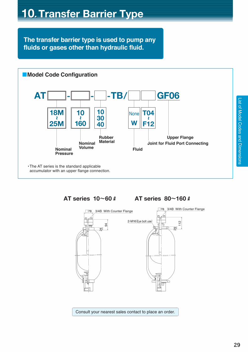
The transfer barrier type is used to pump any fluids or gases other than hydraulic fluid.
- -AT TB GF06-
10~
160
18M~
25M
Nominal Volume
Rubber Material
�Nominal Pressure
• The AT series is the standard applicable accumulator with an upper flange connection.
10. 10. Transfer Barrier Type
AT series 10~60 R AT series 80~160 R
152
40
112
A
φC
29B
対辺100φ110200
G3(PF)
29
□78
2-M16(Eye bolt use)40
A
φC
37 B
対辺100φ110200
G2(PF)
152
94A
φC
24B
対辺71φ76φ100
G2(PF)
24
Rc3/4(PT)
対辺65
JIS B 2401 G55
□78 3/4B With Counter Flange 3/4B With Counter Flange
Consult your nearest sales contact to place an order.
103040
Fluid
None
W
Joint for Fluid Port Connecting Upper Flange
T04~
F12
List of Model Codes and Dim
ensions
/
30
11. 11. Piston Type Accumulator
■Model Code Configuration
- - /Nominal Volume�Nominal
Pressure
Material of O-rings
(Note) In case of ambient temperature always exceeding 80°C, TR Cap cannot be used.
20.6
20.6
20.6
123445
101020304050
100
140
200
A
B
C
Type Standard Product Model
Maximum WorkingPressureMPa
Dimension mm
PA210- 1-30/T06(E)
PA210- 2-30/T06(E)
PA210- 3-30/T06(E)
PA210- 4-30/T06(E)
PA210- 4-30/T08(E)
PA210- 5-30/T08(E)
PA210-10-30/T08(E)
PA210-10-30/T08(E)
PA210-20-30/T08(E)
PA210-30-30/T08(E)
PA210-40-30/T08(E)
PA210-50-30/T08(E)
Gas Volume
R
13161820374055
128166202238275
H340(357)
468(485)
595(612)
722(739)
489(507)
554(572)
879(897)
703(718) 1032(1047)
1348(1363)
1660(1675)
1991(2006)
Masskg
Innermm
128256383510254319644283612928
12401571
Strokemm
Rc 3/4
Rc 1
Rc 1
ThreadTD
114.3
165.2
241.8
220〔700〕
450〔1400〕
450〔2800〕
Without TR CAP
KW6936 A4
KW6937 A4
KW6938 A4
KW6939 A4
KW6940 A4
KW6941 A4
KW6942 A4
KW6943 A4
KW6944 A4
KW6945 A4
KW6946 A4
KW6947 A4
With TR CAP
KW6924 A4
KW6925 A4
KW6926 A4
KW6927 A4
KW6928 A4
KW6929 A4
KW6930 A4
KW6931 A4
KW6932 A4
KW6933 A4
KW6934 A4
KW6935 A4
Product CodeMaximum Discharge Flow RateR/min
Note: Values in the 〔 〕 represent the maximum discharge flow obtained by changing the bore of the joint for fluid port connecting.
Notes: ( ) with TR Cap Please designate Model Code and Product Code in your order. Consult your nearest sales contact to place an order for a fixing band.
PA series FOR HIGH PRESSURE AND BIG VOLUME, WE CAN DESIGN FREELY
The Original Seal Makes The Accumulator Have Low Friction And High Sealing Ability.
PA 210NoneE(Note)
Joint for Fluid Port Connecting
Specifications Required by the Gas Side
Type A Type B Type C
H
Stro
ke
φD
TT Across Flats 65φ76Across Flats 65φ76
Stro
ke
T Hex. 36
H
Stro
ke42
28
H31
5413
13
φD φD
The following list is of representative sizes. Please consult your nearest sales contact for any other size.
Symbol Material Fluid Temperature Note
30 NBR(Standard Nitrile Rubber) Common Mineral Hydraulic Oil -20〜100°C Standard
Material
10NBR
(Nitrile Rubber for Low Temperature Use)
Common Mineral Hydraulic Oil -40〜80°C Material For Low Temp.
70 FKM(Fluororubber)
Common Mineral Hydraulic OilPhosphoric Ester Hydraulic Oil -15〜150°C
(Note) For High Temp., For Chemicals
(Note) If the maximum working temperature exceeds 100 °C, then ensure to consult your nearest sales contact as it will require a special design.
31
A
B
C
Type
12. 12. Expansion Tank
■Model Code Configuration
- -
Nominal Volume�Nominal
Pressure
Symbol
52For Type A (0.5, 1, 2 R)
50For Type B(10, 20 R)For Type C(20 R)
Material
CM(Chlorinated Polyethylene)
Fluid
Potable Water,Industrial Water
Rubber MaterialTemperature
-10〜85°C
ET series LOW-PRESSURE ACCUMULATOR FOR WATER
Accumulator for Potable Water that is of Excellent Chlorine Resistance
ET
Type A Type B Type C
H
φD
H
φD
H
TT T Hex. 55
φD47
0.45
0.5
0.85
2.0
0.6 1.0 2.0 11.5 18.6 20
0.6 0.8 1.4 4.5 6.0 20
Model Code Product CodeMaximum Working
PressureMPa
Dimension mm
ET4.5-0.5-52
ET4.5-1-52
ET5-2-52
ET8.5-10-50
ET8.5-20-50
ET20-20-50
Gas Volume
R
Masskg
G1/2G1/2G 3/4R 3/4R 3/4Rc11/4
ThreadT
134201219375440472
112112143233273309
H D
30
90
90
KE7522 J4〜KE7523 S4
KE7524 J4〜KE7525 S4
KE7526 J4〜KE7527 S4
KE5671 D4
KE5672 E4
KE6957 E4
Maximum Discharge Flow RateR/min
● Note that Type A (0.5, 1 and 2 R) cannot be refilled with gas. Use at 40 °C or less is recommended. Also, the product is delivered filled with nitrogen gas at the factory. Please ensure to let us know the desired gas pressure (___MPa at ___°C) when placing an order. Pressure can be specified from 0.04 MPa to 0.3 MPa in 0.01 MPa increments.● Type B (10 and 20 R) and Type C (20 R) can be refilled with gas.
Please designate Model Code and Product Code in your order. Type A has different Product Codes for the differing filled gas pressures. Consult your nearest sales contact for more details.
List of Model Codes and Dim
ensions
32
In order to make the accumulator be easily connected, there has prepared bushing and flange of various sizes. Please place order with accumulator.Selecting of bushing and flange should be in accord with joint mount thread of accumulator fluid port.
BushingFlange
O-ring
Joint mount thread
Joint mount thread
O-ring
Connecting pipe(Welding)
Manifold of machinery
Thread of connecting tube
O-ring
Counter flange
Bolt
Bolt
O-ring
O-ring
Manifold of machinery
O-ring
O-ring
Bolt
q Bushing (With O-ring and Backup Ring)
T03
T04
T06
T04
T06
T08
T04
T06
T08
T10
T06
T08
T10
T12
R3/8
R1/2
R3/4
R1/2
R3/4
R 1
R1/2
R3/4
R 1
R11/4
R3/4
R1
R11/4
R11/2
8
30
10
28
13
40
Rc3/8
Rc1/2
Rc3/4
Rc1/2
Rc3/4
Rc1
Rc1/2
Rc3/4
Rc1
Rc11/4
Rc3/4
Rc1
Rc11/4
Rc11/2
32
36
50
76
108
PAL101-049
PAL101-050
PAL101-051
PAL101-052
PAL101-053
PAL101-054
PAT101-028
PAT101-029
PAT101-030
PAT101-031
PAT101-032
PAT101-033
PAT101-034
PAT101-035
EB1701 Z1
EB1702 Z1
EB1703 Z1
EB1704 Z1
EB1705 Z1
EB1706 Z1
EB1707 Z1
EB1708 Z1
EB1709 Z1
EB1710 Z1
EB1711 Z1
EB1712 Z1
EB1713 Z1
EB1714 Z1
PA (Type A)
AL1, 2.4 R (G3/4)
AL4, 5 R (G11/4)
PA (Types B,C)
AT10〜60 R (G2)
AT-HF, MHAT80〜160 R (G3)
B A
CG3/4
(G1 1/4)
F
F
B CG2
Section X-O-X’
φA 65X’
X
O
Section Y-O-Y’
95Y’
Y
O
B
C
G3
F(With Backup Ring T2)
φA
JIS B24011B P22
AS568-222Former AN6227#27 (NBR90°)
JIS B24011B G55
AS568-336Former AN6227#39 (NBR70°)
A B C Model Code Product Code
Bushing Flange
Thread Size of
Connect-ing Tube
SymbolApplicable
Accumulator(Joint Mount
Thread)
Dimension mm O-ring Applied on “F”Common Mineral [ Hydraulic Oils]
FigurePurchase separately
When purchasing without accumulator ● Please designate Model Code and Product Code. Material: Steel (Standard Material) ● Stainless steel is also available.
F Type and H Type Flange D Type Flange D Type Flange for UH type
13. 13. Joint for Fluid Port Connecting
33
【Information】JIS B 2291 Counter Flange Dimension
SSA15
SSA20
SSA25
SSA32
SSA40
SSA50
SSA65
SSA80
1B G25
1B G30
1B G35
1B G40
1B G50
1B G60
1B G75
1B G85
54
58
68
76
92
100
128
140
22
22
28
28
36
36
45
45
16
20
25
31.5
37.5
47.5
60
71
36
40
48
56
65
73
92
103
11
11
13
13
18
18
22
24
22.2
27.7
34.5
43.2
49.1
61.1
77.1
90
11
12
14
16
18
20
22
25
GB
□D□A
H 4-φE
φF
φC
A B C D E F GNominal
Bore Size
Dimension mm O-ring Applied on “H”JIS B2401
[Common Mineral Hydraulic Oils]Figure
w FlangeF-Type Flange Set (With Counter Flange, Bolts, O-rings, Backup Ring)Maximum Working Pressure: 21 MPa
F04
F06
F06
F08
F06
F08
F10
F12
F12
F16
F20
F24
F04
F06
F08
F10
F12
F16
F20
F24
15A(1/2B)
20A(3/4B)
20A(3/4B)
25A(1B)
20A(3/4B)
25A(1B)32A
(11/4B)40A
(11/2B)40A
(11/2B)50A
(2B)65A
(21/2B)80A
(3B)
SSA15
SSA20
SSA20
SSA25
SSA20
SSA25
SSA32
SSA40
SSA40
SSA50
SSA65
SSA80
75
75
108
80
108
128
128
138
178
198
38
38
43
38
40
36
45
16
20
20
25
20
25
30
37
37.5
47.5
60
71
36
40
40
48
40
48
56
65
65
73
92
103
M10
M10
M12
M10
M12
M16
M16
M20
M22
PAL101-056
PAL101-057
PAL101-058
PAL101-059
PAT101-036
PAT101-037
PAT101-038
PAT101-039
PAT101-101
PAT101-102
PAT101-103
PAT101-104
EB1715 Z1
EB1716 Z1
EB1717 Z1
EB1718 Z1
EB1719 Z1
EB1720 Z1
EB1721 Z1
EB1722 Z1
EB1742 Z1
EB1743 Z1
EB1744 Z1
EB1745 Z1
AL1, 2.4 R (G3/4)
AL4, 5 R (G11/4)
AT10〜60 R AT-SH type (G2)
AT-HF, MHAT80〜160 R (G3)
B □DG3/4
O-ring: JIS B 2401 1B P22φ
Aφ
C4-E Tap
B □DG1 1/4
O-ring: AS568-222(Former AN6227#27) NBR90°
O-ring: AS568-336(Former AN6227#39) NBR70°(With Backup Ring T2)
φAφ
C
4-E Tap
B □DG2
φAφ
C
4-E Tap
□D
4-E Tap
O-ring: JIS B 2401 1B G55
φC
BG3
φA
A B C D E Model Code Product Code
Connect-ing Pipe
Bore SizeSymbol
Counter Flange
JIS B2291
Dimension mmFigure(Applied O-ring: For Common
Mineral Hydraulic Oils)
Purchase of Flange Set
When purchasing without accumulator ● Please designate Model Code and Product Code. Material: Steel (Standard Material) ● Stainless steel is also available.
Applicable Accumulator(Joint Mount
Thread)
Accessories and Parts
Symbol
34
Counter Flange Dimension
15A(1/2B)
20A(3/4B)
25A(1B)
32A(11/4B)
40A(11/2B)
50A(2B)
65A(21/2B)
80A(3B)
1B G25
1B G30
1B G35
1B G40
1B G50
1B G60
1B G75
1B G85
74
78
90
100
118
134
170
186
25
25
32
32
40
45
55
55
16
20
25
30
38
47.5
60
71
44
49
57
65
75
88
110
124
14
14
18
18
22
22
26
32
22.2
27.7
34.5
43.2
49.1
61.1
77.1
90
10
17
19
20
23
25
28
31
A B C D E F GConnecting
Pipe Bore SizeDimension mm
Figure
H-Type Flange Set (With Counter Flange, Bolts, O-rings, Backup Ring)
Maximum Working Pressure: 35 MPa
H04
H06
H06
H08
H06
H08
H10
H12
H16
H20
H24
15A(1/2B)
20A(3/4B)
20A(3/4B)
25A(1B)
20A(3/4B)
25A(1B)32A
(11/4B)40A
(11/2B)
50A(2B)
65A(21/2B)
80A(3B)
86
93
93
108
93
108
118
138
158
198
228
42
42
42
42
42
42
42
44
45
55
55
16
20
20
25
20
25
30
37
47.5
60
71
44
49
49
57
49
57
65
75
88
110
124
M12
M12
M12
M16
M12
M16
M16
M20
M20
M24
M30
PAL101-060
PAL101-061
PAL101-062
PAL101-063
PAT101-043
PAT101-044
PAT101-045
PAT101-046
PAT101-116
PAT101-117
PAT101-118
EB1726 Z1
EB1727 Z1
EB1728 Z1
EB1729 Z1
EB1730 Z1
EB1731 Z1
EB1732 Z1
EB1733 Z1
EB1761 Z1
EB1762 Z1
EB1763 Z1
AL1, 2.4 R (G3/4)
AL4, 5 R (G11/4)
AT10〜60 R AT-SH (G2)
AT-HF, MH AT80〜160 R (G3)
A B C D E Model Code Product Code
Connect-ing Pipe
Bore SizeSymbol
Dimension mmFigure(Applied O-ring: For Common
Mineral Hydraulic Oils)
Purchase of Flange Set Applicable Accumulator
(Joint Mount Thread)
O-ring Applied on “H”JIS B2401
[Common Mineral Hydraulic Oils]
H04
H06
H08
H10
H12
H16
H20
H24
Symbol
B □DG3/4
O-ring: JIS B 2401 1B P22φ
Aφ
C4-E Tap
B □DG1 1/4
O-ring: AS568-222(Former AN6227#27) NBR90°
O-ring: AS568-336(Former AN6227#39) NBR70°(With Backup Ring T2)
φAφ
C
4-E Tap
B □DG2
φAφ
C
4-E Tap
□D
4-E Tap
O-ring: JIS B 2401 1B G55
φC
BG3
φA
GB
□D□A
H 4-φE
φF
φC
When purchasing without accumulator ● Please designate Model Code and Product Code. Material: Steel (Standard Material) ● Stainless steel is also available.
O-ring:AS568-336(Former AN6227#39) NBR70°(With Backup Ring T2)
A B C D E Model Code Product Code
Connect-ing Pipe
Bore SizeSymbol
Dimension mmFigure(Applied O-ring: For Common
Mineral Hydraulic Oils)
Purchase of Flange Set
AL1, 2.4 R (G3/4)
AL4, 5 R (G11/4)
AT10〜60 R AT-SH type (G2)
AT-HF, MH AT80〜160 R (G3)
AT-UH
(M105×2 ) male thread
Applicable Accumulator(Joint Mount
Thread)
O-ring Applied on “G”
JIS B2401Common Mineral [ Hydraulic Oils]
Accessories and Parts
When purchasing without accumulator ● Please designate Model Code and Product Code. Material: Steel (Standard Material) ● Stainless steel is also available.
36
14. 14. Accumulator Stop Valve(Maximum Working Pressure: 21 MPa)
Accumulator stop valve is the multiple valve which consists of a main valve and a drain valve.Fluid pressure can be relieved by shutting the main valve and opening the drain valve, which facilitates the checking of the filled gas pressure and the replacement of the accumulator and the bladder.
■Model Code Configuration
×10HF-ACC- -
10203240
Accumulator size
T: Drain Piping Size: 3/8 (10A)
Symbol of Accumulator Stop Valve
P: Main Piping Size
Consult your nearest sales contact if you need the product whose maximum working pressure is over 21MPa.
■JIS Symbol Mark
アキュムレータ元弁
P T
By Accumulator Size
Full-open heightapprox.H
φF
φW
T1L3
L1 LT E
BAφ
17.8
L2Fu
ll-op
en h
eigh
t
appr
ox.H
1
φW1
C9
Model Code
Dimension mmFlange Dimension
HF-ACC-10×10-□
HF-ACC-20×10-□
HF-ACC-32×10-□
HF-ACC-40×10-□
Main Piping Size
P
Drain Piping SizeT
MasskgL L1 L2 L3 T T1 H H1 W W1
A B C E F100100110140
142142164210
47.547.560.569.0
50506080
21212735
25252525
58587692
40405665
33333336
9121618
17.827.743.249.1
141141202209
96 96109114
120120180160
80808080
6.0 6.213.522.5
10A(3/8B)
20A(3/4B)
32A(11/4B)
40A(11/2B)
3/8B(10A)
When purchasing without accumulator ●Please designate Accumulator size and main piping size. ●At occasion of applying other hydraulic fluid than mineral oils, please inform applied fluid.
Symbol Accumulator Size20
32
50
80
AL1, 2.4 RAL4, 5 RAT10, 20, 30, 40, 50, 60 R, All SH typeAT80, 120, 150, 160 R, HF, MH
Accumulator Stop Valve
37
14. Accumulator Stop Valve(Maximum Working Pressure: 21 MPa)
In case of ambient temperature always exceeding 80°C, TR Cap cannot be used.
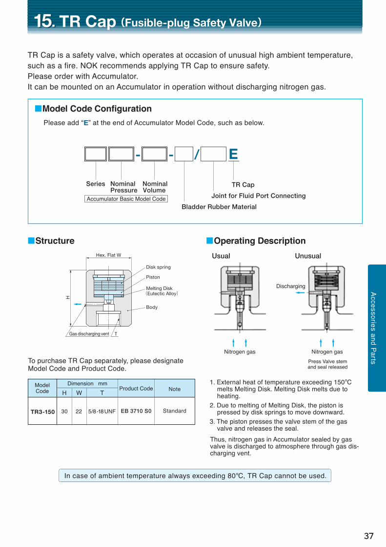
15. 15. TR Cap(Fusible-plug Safety Valve)
TR Cap is a safety valve, which operates at occasion of unusual high ambient temperature, such as a fire. NOK recommends applying TR Cap to ensure safety. Please order with Accumulator.It can be mounted on an Accumulator in operation without discharging nitrogen gas.
1. External heat of temperature exceeding 150°C melts Melting Disk. Melting Disk melts due to heating.
2. Due to melting of Melting Disk, the piston is pressed by disk springs to move downward.
3. The piston presses the valve stem of the gas valve and releases the seal.
Thus, nitrogen gas in Accumulator sealed by gas valve is discharged to atmosphere through gas dis-charging vent.
■Model Code Configuration
E/- -
TGas discharging vent
H
Hex. Flat W
Disk spring
Piston
Melting Disk(Eutectic Alloy)
Body
■Structure ■Operating Description
Press Valve stem and seal released
c cNitrogen gas
c cNitrogen gas
Dischargingb
Usual Unusual
Accessories and Parts
Standard
Model Code NoteProduct Code
Dimension mm
TR3-150 30 22
H W
5/8-18UNF
T
EB 3710 S0
Please add “E” at the end of Accumulator Model Code, such as below.
To purchase TR Cap separately, please designate Model Code and Product Code.
Bladder Rubber Material
TR Cap
Joint for Fluid Port Connecting
Series
Accumulator Basic Model Code
Nominal Volume
Nominal Pressure
38
16. 16. Gas Control Valve
The gas control valve not only facilitates the filling of the gas and the gas pressure to be checked but also incorporates a safety valve function.Two types of safety valve are available: fuse metal or spring type.Either valve can be selected when ordering an accumulator.
● An adapter is required to attach a valve to an existing accumulator. Consult us and ensure to provide the Model Code of the accumulator concerned.
●Consult us if you need the pressure gauge in any other unit than MPa.●Please designate Model Code in your order.
■Model Code Configuration
(GC ) GC /- -
Rubber MaterialGas Control Valve
Joint for Fluid Port Connecting
Series
Basic Model of the Accumulator
Model Code of the Gas Control ValveModel Code of the Accumulator
Model Code Pressure Gauge Fuse Metal Safety Valve Spring Safety ValveSafety Valve Specifications
Fuse Metal Safety ValveGC 10- 35M-□
GC 35- 35M-□
GC 70- 35M-□
GC 70- 70M-□
GC160- 70M-□
GC160-150M-□
GC250-150M-□
GC250-175M-□
GC250-210M-□
GC250-250M-□
GC350-250M-□
GC350-300M-□
GC500-300M-□
GC500-350M-□
Spring Safety ValveGC 10- 35-□
GC 35- 35-□
GC 70- 35-□
GC 70- 70-□
GC160- 70-□
GC160-150-□
GC250-150-□
GC250-175-□
GC250-210-□
GC250-250-□
GC350-250-□
GC350-300-□
GC500-300-□
GC500-350-□
10 35
70
160
250
350
500
0〜1.00〜3.5
0〜7.0
0〜16
0〜25
0〜35
0〜50
6060
60
60
60
75
75
35
70
150
175210
250
300
350
3.43
6.86
14.7
17.220.6
24.5
29.4
34.3
5.15
10.3
22.1
25.730.9
36.8
44.1
51.5
35
70
150
175210
250
300
350
3.43
6.86
14.7
17.220.6
24.5
29.4
34.3
3.82
7.55
16.2
18.922.6
27.0
32.4
37.3
Ensure the “Maximum working pressure of the accumulator ≤ Maximum working pressure of the safety valve” when selecting a safety valve.
39
■JIS Symbol Mark
Fuse MetalSafety Valve
SpringSafetyValve
176℃
A BC
Accumulator
Intake and Exhaust Gases
Air ReleaseD
Structure of Fuse Metal Safety Valve
Safety Valve Nut
Fuse Metal
SealPacking
MAX. 156
Gas Control Valve
Fuse Metal Safety Valve
O-ring: AS568-214(Former AS6227#19)NBR70°
The product comes with an adapter.
Backup Ring: T2
Pressure Gauge
D
B
A
M35×1.5C 67
220 (
238 )
*1
6090C
Hose Assembly Connection*1: Values in the ( ) provide the dimensions of a φ75 pressure gauge.
*1: Values in the ( ) provide the dimensions of a φ75 pressure gauge.
*2: Values in the ( ) provide the dimensions of the GC□-300 and 350.
Spring Safety Valve Pressure Gauge
238 (
303 )
*2
MAX. 156
67
MAX. 156
Gas Control Valve
Fuse Metal Safety Valve
Pressure Gauge
D
B
A
C
205 (
223 )
*1
60(79)C
Hose Assembly Connection *2: Values in the ( ) provide the dimensions of the GC□-300 and 350.
Spring Safety Valve Pressure Gauge
223 (
288 )
*2
MAX. 156
52(
25)
52(
25)
NOKʼs gas control valve incorporates an independent valve that both protects the pressure gauge and enables any necessary degassing after measuring the pressure.
A: Stop Valve for Safety Valve Maintenance (Always Open)B: Stop Valve for Pressure Gauge Protection (Always Closed)C: Coreless Valve for Gas Intake and Exhaust (Always Closed)
Notes 1: Supports pressure measurements at ambient temperatures of between -5 and 40 °C.
2: Use of the always open Valve B can lead to degradation of the accuracy of or damage to the pressure gauge.
Process Explanationq External heat of temperature exceeding 176 °C melts
Fuse Metal. w Once the pressure of the gas increases to the seal burst
pressure, the pressure of the seal will burst open and release the air.
For AT series [With Fuse Metal Safety Valve] [With Spring Safety Valve]
For AL series [With Fuse Metal Safety Valve] [With Spring Safety Valve]
Accessories and Parts
40
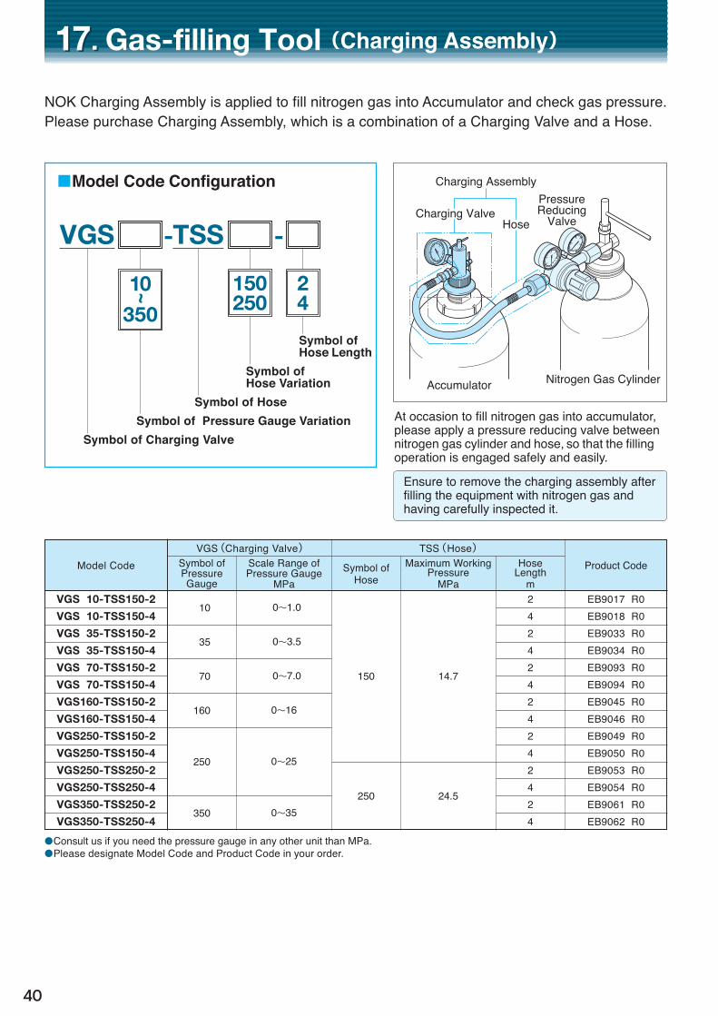
17. 17. Gas-filling Tool(Charging Assembly)
NOK Charging Assembly is applied to fill nitrogen gas into Accumulator and check gas pressure.Please purchase Charging Assembly, which is a combination of a Charging Valve and a Hose.
At occasion to fill nitrogen gas into accumulator, please apply a pressure reducing valve between nitrogen gas cylinder and hose, so that the filling operation is engaged safely and easily.
Charging AssemblyPressureReducing
Valve
Accumulator Nitrogen Gas Cylinder
Charging ValveHose
Ensure to remove the charging assembly after filling the equipment with nitrogen gas and having carefully inspected it.
■Model Code Configuration
- -VGS TSS
10~
350
●Consult us if you need the pressure gauge in any other unit than MPa. ●Please designate Model Code and Product Code in your order.
●Ensure to fix any accumulator 30 R or more in place using two bands.●Please designate Model Code and Product Code in your order.●The products with an asterisk (*) are listed in the previous catalog.
44
19. 19. Assembly and Disassembly Tool
Ensure to use the specialized tools when repairing a bladder type accumulator.
Core Tool Hook SpannerPull RodPull Wire
Hanging Hook
for AT10〜60 R for AT80〜160 R (Two hooks are required per accumulator)
Model Code Core Tool Pull Wire Pull Rod Hook Spanner Hanging Hook
TAL150-1
TAL150-4
TAT150-10
TAT230-120
Product Code
EB1930 T1
EB1931 T1
EB1937 T1
EB1938 T1
AL series
AT series
Applicable Accumulators
1, 2.4 R
4, 5 R
10, 20, 30, 40, 50, 60 R
80, 120, 150, 160 R
○
○
—
—
○
○
—
—
—
—
○
○
○
○
○
—
—
—
○
○
●Please designate Model Code and Product Code in your order.
Sets of specialized tools are available for assembling and disassembling the AL and AT series.Please designate Model Code and Product Code in your order.(Tools with ○ are available in sets.)
Please consult us separately for the products with the CE Marking as they are different in shape.
Tool Name Model Code
Core Tool
Pull Wire
Pull Rod
Hook Spanner
Hanging Hook
Mounting and removing cores
Assembling and removing bladders
Fastening and loosening lock rings
Hanging an accumulator(Ensure to use two hooks with AT 80, 120, 150 and 160 accumulators)
TAL150-1/A
TAL150-1/B
TAT150-10/B
TAL150-1/C
TAL150-4/C
TAT150-10/C
TAT150-10/D
TAT230-120/Z
Product Code
EB1915 T1
EB1933 T1
EB1935 T1
EB1917 T1
EB1918 T1
EB1919 T1
EB1920 T1
EB1928 T1
Applicable Accumulators Purpose
All AL series
All Minilaor series
All AL series
All AT series
AL series 1, 2.4 R
AL series 4, 5 R
AT series 10, 20, 30, 40, 50, 60 R
AT series 10, 20, 30, 40, 50, 60 R
AT series 80, 120, 150, 160 R
Available separately.
45
Bladder replacement kits (with sealing materials) for use in repairing bladder type accumulators are available.
Page
z AL series for 1~5 R ・・・・・・・・・・・・・・・・・・・・・・・・・・・・・・・・・・・・・・・・・・・・・・・・・・・・・・・・・・・・・・・・・・・・・・・・・・・・・・ 46
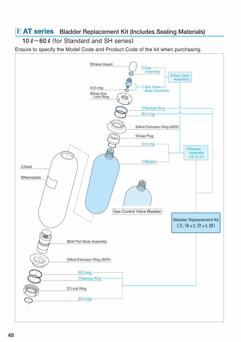
x AT series for 10~60 R and Standard and SH series ・・・・・・・・・・・・・・・・・・・・・・・ 48
c AT series for 10~50 R and HF, MH and UH series ・・・・・・・・・・・・・・・・・・・・・・・・・ 50
v AT series for 80~160 R and Standard, MH and UH series ・・・・・・・・・・・・・ 52
20. 20. Bladder Type Accumulator Replacement Kit
The bladder is an important part of a bladder type accumulator but will eventually need to be replaced.Ensure to replace the bladder as early as possible in thereby preventing any unexpected failures.
To place an order:Specify the Model Code and Product Code of the required bladder replacement kit (includes sealing materials)
If you are unsure exactly which replacement kit to select, ensure to first identify the Model Code and Shell No. of the accumulator to be repaired, then consult your nearest sales contact. We can help select the appropriate one.
The Model Code and Shell No. can be found stamped on the shell shoulder on the gas side.The basic model code is included in the Model Code.
(The Model Code for high flow, middle-high flow,)and ultrahigh flow models is followed by HF.
Accessories and Parts
Model Code(AT○○M-○○)
Shell No.(○○○○)
See the nameplate (below) for products with a specified Product Code.
46
z AL series Bladder Replacement Kit (Includes Sealing Materials)
Ensure to specify the Model Code and Product Code of the kit when purchasing.
■For Gas Control Valve Types (Include O-rings for the gas control valve connection joints and washers for the locking screw)
Please designate Model Code and Product Code in your order.
Rubber material replacement kit for the standard nitrile rubber (material mark: -30).Consult your nearest sales contact if you require any other rubber materials than standard.
48
x AT series Bladder Replacement Kit (Includes Sealing Materials) 10 R~60 R(for Standard and SH series)Ensure to specify the Model Code and Product Code of the kit when purchasing.
60 R AT23M-60GC-30, -SH *AT210-60GC-30, -SH PAT210-60GC-30 EB1340 B1
The products with an asterisk (*) are listed in the previous catalog. Please designate Model Code and Product Code in your order.
Rubber material replacement kit for the standard nitrile rubber (material mark: -30).Consult your nearest sales contact if you require any other rubber materials than standard.
50
c AT series Bladder Replacement Kit (Includes Sealing Materials) 10 R~50 R(for HF, MH and UH series)Ensure to specify the Model Code and Product Code of the kit when purchasing.
The products with an asterisk (*) are listed in the previous catalog. Please designate Model Code and Product Code in your order.
Rubber material replacement kit for the standard nitrile rubber (material mark: -30).Consult your nearest sales contact if you require any other rubber materials than standard.
52
v AT series Bladder Replacement Kit (Includes Sealing Materials) 80 R~160 R(for Standard, MH and UH series)Ensure to specify the Model Code and Product Code of the kit when purchasing.
The products with an asterisk (*) are listed in the previous catalog. Please designate Model Code and Product Code in your order.
Rubber material replacement kit for the standard nitrile rubber (material mark: -30).Consult your nearest sales contact if you require any other rubber materials than standard.
54
21. 21. Accumulator Handling Precautions
1. Verify using the nameplate of the accumulator that it is in fact the product you ordered.2. Never use an accumulator at a pressure exceeding its maximum working pressure.3. Install the accumulator firmly by the fixing band or other means.4. Typically the equipment will not have been filled with nitrogen gas when shipped from the
factory. Ensure to fill with gas prior to use. Ensure not to use an accumulator before being filled with gas or the bladder could be damaged. (The MU, MUV and ET series are delivered with nitrogen gas filled at a factory.)5. Ensure to fill the accumulator with nitrogen gas.
6. Ensure to attach a reduction valve to the nitrogen cylinder so that the gas can be filled in a safe and easy manner.
7. Ensure to release the fluid pressure before filling with gas or checking the gas pressure. Before releasing the fluid pressure ensure to utilize a bypass pipe (depressurizing pipe) or drain
positioned between the main pipe and the accumulator.8. Carry out the periodic maintenance and inspections of the accumulator (approximately twice a year). ① Filled Gas Pressure: Add more gas if insufficient.
② Check for any external nitrogen gas or fluid leaks. ③ Check for any damage to the accumulator, loosened screws or other abnormalities.
9. Ensure not to use any other fluid than the factory recommendation or it could result in the bladder being swollen or the lifespan being drastically reduced.
10. Ensure the fluid and gas pressures are at atmospheric pressure before any part disassembly or removal work.
11. Ensure all the nitrogen gas has been removed from the accumulator prior to storage.12. Before disposing of the accumulator ensure to completely remove any nitrogen gas, and then
remove the core, gas valve or gas control valve in thereby ensuring it cannot be reused.
Contact your nearest sales contact regarding any necessary on-site gas filling or part replacement services.
● Never use oxygen or any inflammable gas.● Ensure not to use air as it could also shorten the life of the bladder.
● Ensure adequate ventilation of the room when removing any gas from the accumulator. (The room could become saturated with nitrogen gas and result in an oxygen deficiency.)● Welding or other processing of accumulators is strictly prohibited.
*Nitrogen gas will typically permeate from the bladder causing the gas pressure to drop. (See the next page for gas permeation and usage precautions.)
Gas Permeation and Usage Precautions
55
Handling and Selection
Gases can permeate through rubber and other polymeric membranes. This phenomenon involves the gas dissolving through from either side of the rubber membrane, spreading into the membrane due to the differing concentrations of dissolved gas, and then passing through to the other side of the membrane. Rubber balloons becoming deflated or the drop in air pressure of tires over time are both examples of gas permeation having occurred.
Nitrogen gas in an accumulator will also permeate through the rubber membrane of a diaphragm into the operating oil (fluid).
If an accumulator is left filled with gas or the operating pressure has been retained at the filled gas pressure or less, then little gas will penetrate through as the bladder will be tightly adhered to the shell.
Polymeric Membrane Gas Permeation Model
■Relationship between Temperature of Accumulator and Decrease in Gas Pressure
Gas Side
Gas Molecules
Rubber Membrane
Fluid Side
ブラダがシェルに密着
Time
30℃
50℃
80℃
Fille
d G
as P
ress
ure
Any increase in temperature can accelerate the gas permeation process. Constant use of an accumulator in a high temperature region, therefore, will require more frequent than usual gas pressure inspections and refills. If Type A (0.5, 1 or 2 R) of the MU or ET series, which is rather small in volume and incapable of being refilled with gas, is always used in a high temperature region then the useful lifespan will be less than usual.
Please consult your sales contact if you have any inquiries regarding the gas permeation process and inspection frequency.
Bladder Tightly Adheres to Shell
56
22. 22. High Pressure Gas Safety Law and Procedure
The use of accumulators in Japan is subject to the “High Pressure Gas Safety Law” and “Industrial Safety and Health Law”.The High Pressure Gas Safety Law has precedence over any others with use of accumulators of any volume used at a pressure of 1 MPa or more. Customers using any accumulator subject to the “High Pressure Gas Safety Law” may be required to apply for permission or submit a notification regarding their use to the prefectural governor. Whether or not an application is required can be determined using the below flowchart, and ensure to contact your nearest sales contact if you do as they can provide you with the necessary documents.
Follow the latest regulations as they are constantly updated.
■ Flowchart of Legal Classification and Necessity for Permission or Notifications regarding Use
0.2 MPa or more, internal volume of 40R or more, inside body diameter of 200 mm or more, and body length of 1000 mm or more
(High Pressure Gas Safety Law)High pressure gas
production equipment
Example Accumulator that does not require Permission or Notifications
Accumulator, Gas Pressure(Gauge Pressure at Normal Temperature)
*3 *3
*2
*1
From a safety perspective a spring safety valve or fusible plug, etc. is desirable.
Must include a relief valve or regulator.
At least one must be observedAccumulator
Liquid Phase(e.g. Oil Used)
Satisfies the following conditionsDoes not satisfy the following conditions
*4Throughput
*5300 m3/dayor more
*5
*6
Less than300 m3/day
Class 1 producer Class 2 producer Other production
Permission ornotification
not requiredNo notification
requiredNo applicable
law
Testing required(tested by NOK)
(Industrial Safety and Health Law)Class 2 Pressure Vessel
1 MPa or moreLess than 1 MPa
Other than
on the right
Application for permission regarding use from prefectural governor required
Submission of notification regarding
use to prefectural governor required
NitrogenGas
Conditional (No permission or notification is required)
As per Article 13 of the General RuleAny accumulator that satisfies all the following conditions falls under “Other Production” and therefore does not require any special permission or notifications:(1) Filled with inert gas or air;(2) Not connected to any external gas source via pipes; and (3) Structurally limited pressure is below the design pressure
(The following a or b must be satisfied: )a. The accumulator is equipped with a spring safety
valve, fusible plug, pressure release plate, etc.b. The pipe connected to the liquid phase of the
accumulator is equipped with a relief valve or automatic pressure controller.
57
Notes (Information with regard to the asterisks)
*1. As per Article 2, Paragraph 1 of the Law.
*2. The “High Pressure Gas Safety Law” deems accumulators, unlike other regular cylinders, to be “high-pressure gas production equipment” that produces highly pressurized gas.
Those customers using the equipment or machine equipped with the accumulator are deemed to be the producers of high-pressure gas.
*3. Any accumulator not satisfying those conditions requires the permission of or notifications regarding use to the prefectural governor.
Permission or notification applications require documents concerning the accumulator. Please ensure to request any such documents when purchasing an accumulator.
Documents NOK provides include: “Tested by a Qualified Tester, etc. Certification”, or “Record of High Pressure Gas Equipment, etc. Test”, “Strength Calculation Document”, “Material Certificate”, “Structural Drawings”, etc.
*4. Article 2, Paragraph 18 of General Rule: Throughput
Throughput Q9 = V9 × 10 P9
Q9: Throughput of Accumulator (m3/day) V9: Internal Volume of Accumulator (m3) P9: Maximum Compression Pressure of Accumulator (MPa) (Converted to at 0 °C and 0 Pascal)
Example Calculation: When an accumulator with a gas volume of 150 R is used at the normal temperature of 50 °C and a maximum working pressure of 21 MPa:
*5. “Nitrogen” according to Article 5, Paragraph 1, of the Law and Article 3, Paragraph 1, of the Cabinet Order.
*6. Other Production Accumulators that do not fall under being concerned with a Class 1 Producer or Class 2 Producer do
not require permission from or notifications regarding use to the prefectural governor. (They fall under being part of “Other Production” if they satisfy all the conditions.)
Personnel filling an accumulator with gas do not require any particular qualifications unless the accumulator is intended to be part of the sales of gas.
Handling and Selection
■Example of Energy Conservation Resulting from Use of an Accumulator
58
The accumulator volume is basically calculated on the basis of P1V1n = P2V2n = P3V3n, although the formula used can vary by application. See the following methods of calculation and examples.
[Methods of Calculation used in Individual Applications and Examples] Page
q Energy Accumulation ・・・・・・・・・・・・・・・・・・・・・・・・・・・・・・・・・・・・・・・・・・・・・・・・・・・・・・・・・・・・・・・・・・・ 60
w Pulse Absorption ・・・・・・・・・・・・・・・・・・・・・・・・・・・・・・・・・・・・・・・・・・・・・・・・・・・・・・・・・・・・・・・・・・・・・・・・・・・ 62
e Impact Absorption ・・・・・・・・・・・・・・・・・・・・・・・・・・・・・・・・・・・・・・・・・・・・・・・・・・・・・・・・・・・・・・・・・・・・・・・・・ 64
r Thermal Expansion Compensation ・・・・・・・・・・・・・・・・・・・・・・・・・・・・・・・・・・・・・・・・ 66
23. 23. Accumulator Volume Calculation
The comparison between the required power with and without an accumulator included in the systems below indicates the use of an accumulator can reduce the necessary power to around a twentieth of that without one.
Necessary Discharge Flow of Accumulator = Required Amount of Oil = 1.5 R 1.5 RDischarge Period ————— = 3 s 0.5 R/s Accumulation Period 120 s-3s = 117 sAccumulating Flow 1.5 R/117 s = 0.013 R/s
0.013 R/s
0.013 R/s×21.0 MPa = 0.27 kw
0.5 R/s
0.5 R/s×10.5 MPa = 5.25 kw
AccumulatorWithItem Without
59
Terms Related to Accumulator Pressure Maximum Working Pressure: All accumulators are designed to be used at a specific pressure or lower
as a pressure vessel that contains high pressure gas. This pressure is referred to as the maximum working pressure.
System Pressure: The maximum possible pressure of a circuit, and generally used to refer to the release pressure of a relief valve mounted on the equipment or machinery. The primary condition when selecting an accumulator is therefore that its maximum working pressure be equal to or exceed the system pressure. Select the appropriate Model Code according to the List of Model Codes and Dimensions for each series whenever the maximum working pressure is known.
Maximum Operating Pressure P3 : The maximum applicable pressure at which gas can be compressed in an accumulator.
Minimum Operating Pressure P2 : The minimum pressure when fluid is discharged from an accumulator.Filled Gas Pressure P1 : Seal pressure of nitrogen gas.Average Discharge Pressure Pm : The average pressure of fluid discharged from a pump, etc.Normal Pressure PA : The pressure within a pipe with no impact pressure. Allowable Impact Pressure PB : Maximum allowable impact pressure. The higher the allowable impact
pressure is the smaller in volume the accumulator can be.
Basic Formula Used with and Operating Conditions of AccumulatorsP1V1n = P2V2n = P3V3n
V3
V2
V1
P3
P2P1
Fill with nitrogen gas
Inflow Discharge
Fluid ConnectionEquipment Pipes
P1:Filled Gas PressureP2:Minimum Operating PressureP3:Maximum Operating PressureV1:Gas Volume at P1
V2:Gas Volume at P2
V3:Gas Volume at P3
n :Polytropic Index(Index determined by fluctuation time of gas pressure)
Filled with Nitrogen GasThe bladder expands and
the poppet closes.
Fluid Flowing inWhen the fluid pressure reaches the filled gas pressure the poppet
then opens and accumulation takes place until the pressure reaches the
maximum operating pressure.
Fluid DischargedFluid is discharged until the
minimum operating pressure is reached.
Handling and Selection
P1V1n P3V3
n P2V2n
Energy Accumulation Pulse Absorption Impact AbsorptionMaximum WorkingPressure
High
Pressure
System Pressure
Filled Gas Pressure P1
OperationalRange of
Accumulator
Accumulation
Discharge
Maximum Operating Pressure P3
Minimum Operating Pressure P2
Without Accumulator
ΔP
Average Discharge Pressure Pm
Without Accumulator
Normal Pressure PA
Allowable Impact Pressure PBPres
sure
Am
plitu
de
60
1. Calculate the required gas volume (V1) that fulfills the aims of the usage conditions.■ Set Filled Gas Pressure (P1)
Set the pressure according to either q or w.P1 ≧(1/Max. compression ratio) × P3 must still be satisfied. (See pages 10 and 11 for the maximum compression ratios of the individual series) q If no change in temperature: P1 =(0.8 〜 0.9)×P2
273 + Minimum temperature(Tmin) w Change in temperature takes place: P1 = ———————————————————————— ×(0.8 〜 0.9)× P2 273 + Maximum temperature(Tmax)
■ Set Polytropic Indices (m, n)Indices m and n can be calculated using the formula below or more simply Table 1.If the inflow time exceeds 40s then assume m = 1. 0.63 m or n =(———— + 1.01)(1.94 × 10⁻²× Pm + 1.12 ) Δt 0.5
Δt:Fluctuation Time with Inflow or Discharge (s) ( If Δt is less than 10s then use the values in Table-1 for m and n )■ Calculate Necessary Gas Volume (V1)
1 1 — — P2 n ・P3 m V1 =ΔV ×—————————————— 1 1 1 — — — P1 m (P3 n - P2 n ) Convert the value to the absolute pressure in the calculation if
the accumulator only has to support a pressure of 1 MPa or less. [Absolute Pressure = Gauge Pressure + 0.1013(MPa)]
2. Select the Model Code of the accumulatorSelect an accumulator from any series that satisfies all of Necessary Gas Volume (V1) ≦ Gas Volume of Accumulator, System Pressure (Pmax)≦Maximum Working Pressure, and Necessary Discharge Flow (Q max)≦Maximum Discharge Flow.
q Energy AccumulationWith intermittent operation (i.e. time available for accumulation to take place in the accumulator) the use of an accumulator can enable downsizing of the volume of the pump and motor, thus contributing to greater energy conservation.
2.0 less than 2.0 or more 2.9 2.9 3.9 3.9 4.9 4.9 5.9 5.9 6.9 6.9 7.8 7.8 8.8 8.8 9.8 9.8 10.810.8 11.811.8 12.712.7 13.713.7 14.714.7 15.715.7 16.716.7 17.717.7 18.618.6 19.619.6 21.621.6 23.523.5 25.525.5 27.527.5 29.4
40 to 60 60 to 80 80 to 100 100 to 200 200 to 400 400 to 700 700 or moreLess Than
1010 or MoreLess Than 20 20 to 40 If the Inflow Time Exceeds 40s Then m = 1 can be Consistently Used.
Pm(MPa)
〈Table-1〉List of Polytropic Indices (m and n values)
Description of Symbols Used V1 :Necessary Gas Volume R
ΔV :Necessary Discharge Flow R
P1 :Filled Gas Pressure MPa P2 :Minimum Operating Pressure MPa P3 :Maximum Operating Pressure MPa Pm :Average Operating Pressure MPa (P2 + P3) Pm =—————— 2 m :Polytropic Index when Fluid Flows in n :Polytropic Index when Fluid Is Discharged
m n
Δt(s)
61
Handling and Selection
■Example CalculationSelect an accumulator with the necessary discharge flow [ΔV] set to be 4L for the hydraulic lines and using the maximum operating pressure [P3: 21.0 MPa] and minimum operating pressure [P2: 12.0 MPa].The accumulation period [Δtm] (duration required for the oil to flow into the accumulator and reach the maximum operating pressure) will be 41s and the discharge period [Δtn] (duration required for the oil to be discharged from the accumulator and reach the minimum operating pressure) 10s. The operating temperature should be between -10 and 60 °C.
Page 69 The Volume Calculation Sheet on q Accumulator for Energy Accumulation can be used with:
Applicable FluidTemperature Fluid Temperature ~ ℃ Normal Temperature ℃Conditions Ambient Temperature ~ ℃ Normal Temperature ℃
System Pressure Pmax MPa Maximum possible pressure applied to an accumulator in a circuit, and typically used to refer to the release pressure of a relief valve with the equipment or machinery.Maximum Operating Pressure P3 MPa Maximum pressure of accumulated fluid in the accumulatorMinimum Operating Pressure P2 MPa Minimum pressure when fluid is discharged from the accumulatorAverage Operating Pressure Pm MPa Pm=(P3+P2)/2 Necessary Discharge Flow ΔV R Total amount of fluid required for piston (actuator) operation Accumulation Period Δt m s Time required to accumulate ΔV in the accumulatorDischarge Period Δt n s Time required to discharge ΔV from the accumulator
Volume Calculation SheetqAccumulator for Energy Accumulation
Fill in the columns within the thick frame. Consult your nearest sales contact regarding any additional inquiries.
Data ・ ・
Equipment and Machinery,Installation Position
Set Conditions of Use
■Set Filled Gas Pressure (P1) Set the pressure according to either q or w. P1 ≧ (1/Max. compression ratio)× P3 must still be satisfied. (See pages 10 and 11 for the maximum compression ratios of the individual series)
qIf no change in temperature takes place: P1 = (0.8~0.9)×P2 = 0.85 × = MPa
■Set Polytropic Indices When Accumulated(m) … Pm , Δtm ; Set the indices from the [List of Polytropic Indices] on page 60. When Discharged (n) … Pm , Δtn ;
■Calculate Necessary Gas Volume for Accumulator (V1)
Calculate Necessary Gas Volume V1
Verify Necessary Discharge Flow Qmax
Convert the value to the absolute pressure for use in calculation if the accumulator is used at 1 MPa or less. [Absolute Pressure (MPa) = Gauge Pressure + 0.1013]
(To be completed by NOK)
Name and Section
1 1 ̶ ̶ P2 n ・ P3 mV1 = ΔV × ̶̶̶̶̶̶̶̶̶̶̶̶ 1 1 1 ̶ ̶ ̶ P1 m (P3 n - P2 n )
Select an accumulator with which the necessary discharge flow Qmax will not exceed the maximum discharge flow.Select the AT series if the bladder for the 10R or larger accumulator is replaced from the gas side.
・Select the series according to the relevant Pmax,V1,Qmax.
・Set the rubber material to according to the fluid used and temperature.
・Set the wetted specification to according to the fluid used.・Set the joint for fluid port connecting and specifications required by the gas side.
No. of Necessary Accumulators (V1; R/Accumulator Gas Volume; R/unit) [Rounded to the nearest whole number] = units
Select a NOK Accumulator Model Select a model that satisfies “V1 ≦Accumulator Gas Volume” from the individual series listed on pages 12 to 31
【Model Code of Selected Accumulator】【Gas Volume】
Verify the Discharge Flow ΔVU of the Selected Accumulator
Q max = ΔV× 60/Δt n = × 60 ÷ = R/min
1 1 1 ̶ ̶ ̶ P1 m (P3 n - P2 n ) ̶̶̶̶̶̶̶̶̶̶̶̶ 1 1 ̶ ̶ P2 n ・ P3 m
1. Calculate the required gas volume (V1) that fulfills the aims of the usage conditions.
■ Set Constant (K1) using the Type of Pump → Set the constant using the table on the right.
■ Set Filled Gas Pressure (P1)Set the pressure according to either q or w. q If no change in temperature: P1 =(0.6 〜 0.8)×Pm w Change in temperature takes place: 273 + Minimum temperature(Tmin) P1 = ———————————————————————— ×(0.6 〜 0.8)×Pm 273 + Maximum temperature(Tmax)
■ Set Polytropic Indices (n) Calculate the value using n = 1.41
■ Calculate the Discharge (q) per Pump Rotation Pump Discharge(R/min) q = ——————————————————— No. of Pump Rotations(rpm)
■ Set the Maximum Target Line Pressure (P3) ΔP P3 = Pm + ——— 2 Target Ripple Factor P3 =(1 + ——————————————)× Pm 100 ΔP: Pressure Amplitude with Accumulator P3 - Pm Ripple Factor = ——————— × 100(%) Pm
■ Calculate Necessary Gas Volume (V1)
1 — Pm n q・K1・ (——— ) P1 V1 = ———————————— 1 — Pm n 1 - (——— ) P3
Convert the value to the absolute pressure in the calculation if the accumulator only has to support a pressure of 1 MPa or less.
w Pulse AbsorptionThe use of an accumulator can attenuate pulses generated by a pump and reduce noise and vibration, while also improving stability.
ΔP
PmP3
Line pressure with accumulatorLine pressure without accumulator
Description of Symbols Used V1 :Necessary Gas Volume R
P1 :Filled Gas Pressure MPa Pm :Average Discharge Pressure MPa P3 :Maximum Target Line Pressure MPa q :Discharge per Pump Rotation R/Rotation K1 :Constant that Varies by Type of Pump n :Polytropic Index 1.41(Nitrogen gas)
K1 for Each Individual Type of PumpType of Pump K1
2. Select the Model Code of the accumulatorSelect an accumulator from any series that satisfies all of Necessary Gas Volume (V1) ≦ Gas Volume of Accumulator, System Pressure (Pmax)≦Maximum Working Pressure, and Necessary Discharge Flow (Q max)≦Maximum Discharge Flow.
Absorbing the pulses from high frequency cycles and pipelines can be taken into account if the operating pressure conditions, the pulses and frequency at which they are generated, and the fluid pipe conditions are provided in thereby allowing the result of the accumulator to be increased. Contact your nearest sales contact for more details.
63
Handling and Selection
■Example CalculationSelect an accumulator that attenuates the pulses generated by the following pumps: Type of Pump: Triple Single-Action Plunger Pump Average Discharge Pressure Pm: 17.0 MPa Pump Discharge: 750 R/min Target Ripple Factor: ± 3% No. of Pump Rotations: 1000 rpm
Applicable FluidTemperature Fluid Temperature ~ ℃ Normal Temperature ℃Conditions Ambient Temperature ~ ℃ Normal Temperature ℃
Maximum possible pressure applied to an accumulator System Pressure Pmax MPa in a circuit, and typically used to refer to the release pressure of a relief valve with the equipment or machinery.Average Discharge Pressure Pm MPa The average pressure of fluid discharged from a pump, etc.Target Ripple Factor % □Plunger □Diaphragm
Number
□Gear No. of Teeth □Vane No. of Blades □OtherPump Discharge Specifications Rotations
Volume Calculation SheetwAccumulator Used to Absorb Pulses
Fill in the columns within the thick frame. Consult your nearest sales contact regarding any additional inquiries.
Data ・ ・
Equipment and Machinery,Installation Position
Set Conditions of Use
(To be completed by NOK)
Name and Section
Calculate Necessary Gas Volume V1 Convert the value to the absolute pressure for use in calculation if the accumulator is used at 1 MPa or less. [Absolute Pressure (MPa) = Gauge Pressure + 0.1013]
■Set Filled Gas Pressure (P1) Set the pressure according to either q or w. P1 ≧ (1/Max. compression ratio)× P3 must still be satisfied. (See pages 10 and 11 for the maximum compression ratios of the individual series)
qIf no change in temperature takes place: P1 = (0.6~0.8)×Pm = 0.7 × = MPa
Select the AT series if the bladder for the 10R or larger accumulator is replaced from the gas side.
・Select the series according to the relevant Pmax,V1.
・Set the rubber material to according to the fluid used and temperature.
・Set the wetted specification to according to the fluid used.・Set the joint for fluid port connecting and specifications required by the gas side.
No. of Necessary Accumulators (V1; R/Accumulator Gas Volume; R/unit) [Rounded to the nearest whole number] = units
Select a NOK Accumulator Model Select a model that satisfies “V1 ≦Accumulator Gas Volume” from the individual series listed on pages 12 to 31
R
□Single-action
□Double-action
pcs. pcs.
R/min rpm
Type of Pump K1 Number Single- Double action action 1 0.60 0.25 2 0.25 0.15
Plunger 3 0.13 0.06
Diaphragm 4 0.10 0.06 5 0.06 0.02 6 0.06 7 or more 0.02
Gear and Vane 0.06
1.41
1.41
Type
of P
ump
【Model Code of Selected Accumulator】【Gas Volume】
Room Temperature
17.0
17.03
11.9
17.51
0.75750 1000
0.13
6.05
6.05
AT series Standard NBR (Nitrile Rubber)
Standard Specifications
10
110
AT 25M-10-30/□□
20.0
17.0 ± 3
3
750 1000
17.011.9
17.0
0.130.75
17.51
Common Mineral Hydraulic Oil
Page 70 The Volume Calculation Sheet on w Accumulator Used to Absorb Pulses can be used with:
64
■ Set Filled Gas Pressure (P1)Set the pressure according to either q or w.Ensure P1 ≧(1/Max. compression ratio) × P3 must still be satisfied. (See pages 10 and 11 for the maximum compression ratios of the individual series) q If no change in temperature: P1 =(0.8 〜 0.9)×PA
273 + Minimum temperature(Tmin) w Change in temperature takes place: P1 = ———————————————————————— ×(0.8 〜 0.9)×PA 273 + Maximum temperature(Tmax)
■ Set Allowable Impact Pressure PB The value is generally set to be 110% of the normal pressure PA. PB = 1.1×PA
■ Set Polytropic Indices (n) Calculate the value using n = 1.41
■ Calculate Necessary Gas Volume (V1)
PA V1 = V ×——— P1
Gas Volume at Normal Pressure PA (V) W・ν2・(n - 1) V = ————————————————— n - 1 —— PB n 200・PA・( (——— ) - 1) PA
This formula is used to calculate the volume required to make the impact absorption of the accumulator completely efficient. In reality, however, the effect could be the same with a smaller volume due to pipe resistance and other factors.
Convert the value to the absolute pressure in the calculation if the accumulator only has to support a pressure of 1 MPa or less.
Select an accumulator from the appropriate series that satisfies Necessary Gas Volume (V1) ≦ Gas Volume and the Maximum Working Pressure being equal to or exceeding the System Pressure.
e Impact AbsorptionThe use of an accumulator can enable valves to be rapidly closed or to mitigate the impact pressure resulting from a sudden change in load, thus preventing the equipment from being damaged.
Examples of Impact Absorption a. Shock buffering when a solenoid valve is switched b. Shock buffering when a ram suddenly stops
W
1. Calculate the required gas volume (V1) that fulfills the aims of the usage conditions.
Description of Symbols Used V1 :Necessary Gas Volume R
V :Gas Volume at PA R
P1 :Filled Gas Pressure MPa PA :Normal Pressure MPa PB :Allowable Impact Pressure MPa n :Polytropic Index 1.41(Nitrogen gas)
ρ :Fluid Density kg/m3
d :Pipe Diameter (Inside Diameter) mm L :Pipe Length m Q :Fluid Flow Rate R/min ν :Fluid Velocity m/s W :Fluid Mass kg
2. Select the Model Code of the accumulator
65
Handling and Selection
■Example CalculationSelect an accumulator that can be used to buffer shocks generated when the direction of the flow is changed using a solenoid valve on a hydraulic line. Pipe Diameter d:3/4B Schedule 160(Inside Diameter: 16.2 mm) Pipe Length L:15 m Normal Pressure PA:11.0 MPa Flow Rate Q:250 R/min Fluid Density ρ:900 kg/m3
Select the AT series if the bladder for the 10R or larger accumulator is replaced from the gas side.
・Select the series according to the relevant Pmax,V1.
・Set the rubber material to according to the fluid used and temperature.
・Set the wetted specification to according to the fluid used.・Set the joint for fluid port connecting and specifications required by the gas side.
No. of Necessary Accumulators (V1; R/Accumulator Gas Volume; R/unit) [Rounded to the nearest whole number] = units
Select a NOK Accumulator Model Select a model that satisfies “V1 ≦Accumulator Gas Volume” from the individual series listed on pages 12 to 31
R
【Model Code of Selected Accumulator】【Gas Volume】
Applicable FluidTemperature Fluid Temperature ~ ℃ Normal Temperature ℃Conditions Ambient Temperature ~ ℃ Normal Temperature ℃
System Pressure Pmax MPa Maximum possible pressure applied to an accumulator in a circuit, and typically used to refer to the release pressure of a relief valve with the equipment or machinery.Normal Pressure PA MPa The pressure within a pipe with no impact pressure.
Allowable Impact Maximum supported impact pressure. The higher the value the smaller in volume PB MPa the accumulator can be.Pressure The value is generally set to be 110% of the normal pressure.(P3=11.0×1.1=12.1MPa)Fluid Density ρ kg/m3 Be careful with the units used. The unit used for water is in [1000].Inside Pipe Diameter d mm Pipe Length L m Flow Rate Q R/min Flow Velocity v m/s Not required if the “pipe diameter” and “flow rate” are provided.
■Set Filled Gas Pressure (P1) Set the pressure according to either q or w. P1 ≧ (1/Max. compression ratio)× P3 must still be satisfied. (See pages 10 and 11 for the maximum compression ratios of the individual series)
qIf no change in temperature takes place: P1 = (0.8~0.9)×PA = 0.9 × = MPa
■Set Polytropic Indices (n) Calculate the value using n = 1.41 (nitrogen gas)
■Calculate Maximum Supported Impact Pressure (PB) PB = 1.1 × PA = 1.1 × = MPa
■Calculate Accumulator Gas Volume (VA) when Pressure is PA
W ・V 2 ・( n - 1 ) × 2 × (1.41-1) VA = ̶ ̶̶̶̶̶̶̶̶̶̶̶̶̶̶̶ ̶ = ̶ ̶̶̶̶̶̶̶̶̶̶̶̶̶̶̶̶̶̶̶̶̶̶̶̶ ̶ = R PB n-1 1.41-1 200・PA ×( (̶̶ ̶) ̶ ̶ ̶-1) 200 × × ((̶̶ ̶̶ ̶̶ ) ̶ ̶ ̶̶ ̶-1 ) PA
n 1.41
PA ■Calculate Necessary Gas Volume (V1) V1 = V A × ̶̶ ̶ = × ̶̶̶̶̶̶̶ = R for Accumulator P1
π π■Calculate Fluid Mass (W) W =̶̶ ・d 2・L・ρ・10-6= ̶̶ × 2 × × × 10-6 = kg within the Line 4 4
■Calculate Flow Velocity (v) v = 21.23 × Q/d2 = 21.23 × ÷ 2 = m/s
Volume Calculation SheeteAccumulator Used to Absorb Impact
Calculate Necessary Gas Volume V1 Convert the value to the absolute pressure for use in calculation if the accumulator is used at 1 MPa or less. [Absolute Pressure (MPa) = Gauge Pressure + 0.1013]
Fill in the columns within the thick frame. Consult your nearest sales contact regarding any additional inquiries.
Data ・ ・
Equipment and Machinery,Installation Position
Set Conditions of Use
(To be completed by NOK)
Name and Section
Room Temperature
Common Mineral Hydraulic Oil
11.0
11.0 12.1
7.54
8.387.54 11.09.9
20.222.78
11.0 12.111.0
2.78
20.22
16.2
250 16.2
15 900
AT18M-10-30/ □□
14.0 11.0
12.1
900 16.2 15 250 ̶
9.9
8.38
AT series Standard NBR (Nitrile Rubber)
Standard Specifications
10
110
Page 71 The Volume Calculation Sheet on e Accumulator Used to Absorb Impact can be used with:
66
■ Set Filled Gas Pressure (P1)Ensure P1 ≧(1/Max. compression ratio) × P3 must still be satisfied. (See pages 10 and 11 for the maximum compression ratios of the individual series) 273 + Minimum temperature(Tmin) P1 = ———————————————————————— ×(0.8 〜 0.9)×P2 273 + Maximum temperature(Tmax)
■ Set Allowable Pressure (P3) (Pressure at System Temperature Increase of t2)
r Thermal Expansion CompensationBoth the fluid and the pipes will expand in volume when a closed circuit consisting of pipes full of fluid heats up. The thermal expansion coefficient for almost all fluids is typically a lot larger than that of most materials pipes are made of, and with the thermally-expanded portion of the fluid being greater than that of the pipe material, thus raising the pressu re within the system (i.e. pipes). A rise in pressure within the system may exceed the design limits and thus damage the equipment used in the system. Any such system therefore requires a compensator to allow for the thermal expansion, with an accumulator being very effective.
Description of Symbols Used V1 :Necessary Gas Volume R
Va :Total Amount of Fluid in Pipes (at t1) R
P1 :Filled Gas Pressure MPa P2 :System Pressure at Temperature t1 MPa P3 :System Pressure at Temperature t2 MPa t 1 :Initial System Temperature °C t 2 :Increased System Temperature °C α :Coefficient of Linear Expansion of Piping 1/°C β :Coefficient of Volume Expansion of Fluid 1/°C
■Example CalculationSelect an accumulator that can be used to raise the pressure of a closed-circuit steel pipe 16 meters long with a diameter of φ125 (Schedule 40) from 0.07 MPa at 20 °C to 0.4 MPa at 55 °C.
P2 = 0.07 + 0.1013 = 0.1713 MPa abs P3 = 0.4 + 0.1013 = 0.5013 MPa abs t 1 = 20 °C t 2 = 55 °C α = 10 × 10-6 1/°C(Steel)
β = 7.5 × 10⁻⁴ 1/°C(Common Mineral Hydraulic Oil)
Va = 125.88 × 1600 = 201408 cm3 = 201.41 R 201.41 ×(55 - 20)×(7.5 ×10-4 - 3 ×10× 10-6)×(0.1713/0.1456) V1 =——————————————————————————————————————————— = 9.06 R 1 -(0.1713/0.5013)
The accumulator AL210-10-30 (gas volume: 10 R) or AT18M-10-30 (gas volume: 10 R) would be the most appropriate.
Bore Area of φ125 (Schedule 40) Steel Pipe Outside Diameter of Steel Pipe: 139.8 mm Thickness:6.6 mmArea =π/4×(13.98-0.66×2)2 = 125.88 cm2
1. Calculate the required gas volume (V1) that fulfills the aims of the usage conditions.
Select an accumulator from the appropriate series that satisfies Necessary Gas Volume (V1) ≦ Gas Volume and the Maximum Working Pressure being equal to or exceeding the System Pressure.
2. Select the Model Code of the accumulator
67
The appropriate documents [Accumulator Selection Request] and [Volume Calculation Sheet] can be found on following pages.Please photocopy any pages you require.
Volume Calculation Sheet qAccumulator for Energy Accumulation ・・・・・・・・・・・・・・・・・・・・・・・・・・・・・・・・・・・・ 69
wAccumulator Used to Absorb Pulses ・・・・・・・・・・・・・・・・・・・・・・・・・・・・・・・・・・・・・・・・ 70
eAccumulator Used to Absorb Impact ・・・・・・・・・・・・・・・・・・・・・・・・・・・・・・・・・・・・・・・・ 71
Unit Conversion Table ・・・・・・・・・・・・・・・・・・・・・・・・・・・・・・・・・・・・・・・・・・・・・・・・・・・・・・・・・・・・・・・・・・・・・・ 72
24. 24. Attached DocumentsH
andling and Selection
68
Accumulator Selection Request□Check the applicable boxes. Please consult your nearest sales contact regarding anything you do not understand. Date Received
Company and Section
Contact Person
Purpose of Accumulator
Equipment and Machinery,Installation Position
Specifications □Without□With *
(To be completed by NOK)
Branch, Agent, and Person in Charge
Result of Selection Date of Response ・ ・ Name and Department
Model Code
Product Code × units
Recommended Filled Gas Pressure MPa at °C
(To be completed by NOK)
Tel.
Installation Site □ Indoors □Outdoors Operating Time Required of Equipment Hours/DaysFluid Temperature ~ ℃ Normal Temperature ℃Ambient Temperature ~ ℃ Normal Temperature ℃□Common Mineral Hydraulic Oil □Phosphoric Ester Operating Oil □ Industrial Water □Other Types
Maximum pressure of accumulated fluid in the accumulator
Minimum pressure when fluid is discharged from the accumulator
Time required to accumulate ΔV in the accumulator
Time required to discharge ΔV from the accumulator
Average pressure of fluid discharged from pumps
□Single-action
□Double-action
□□□□
TemperatureConditions
Applicable Fluid
MPaMPaR
s s
MPa± %
pcs.
pcs.
R/min
rpm
System Pressure
Type
of P
ump
Regu
lator
y Te
stJo
int fo
r Flui
d P
ort C
onne
cting
Spec
ificat
ions R
equir
ed
by th
e Ga
s Side
Maximum Operating PressureMinimum Operating PressureNecessary Discharge Flow ΔVAccumulation PeriodDischarge Period
□No Test Required (Eagle Industry Standard)□No Joint Required□Bushing
□Flange
□With TR Cap□Without TR Cap
□Gas Control Valve
3. Specifications2. Application and Operating Conditions
Maximum possible pressure applied to an accumulator in a circuit, and typically used to refer to the release pressure of a relief valve used with the equipment or machinery.
*Write the Specification No. in the last column if anything specific is required.
Consult your nearest sales contact for any cases where the accumulator will not be installed vertically with the gas side upward. If the accumulator is not installed vertically the possibility of “the necessary discharge not occurring” or “a shortened lifespan of the bladder” exist.
Only fill in the applicable columns.qEnergy Accumulation
Pressure in pipes with no impact pressureMaximum supported impact pressure. The higher the value the smaller in volume the accumulator can be.Be careful with the units used. The unit used for water is in [1000].
Not required if the “pipe diameter” and “flow rate” are provided.
□High Pressure Gas Safety Law □Chinese Regulations□Class-2 Pressure Vessel □CE Mark□ASME□Other
Connection ThreadConnection Diameter
Type □Eagle Industry □Other
(Standard Eagle Industry Specification)
Safety □Fuse Metal Type Valve □Spring Type
Unit of Pressure ScaleGauge Max.Scale
Rc A□F type □H type □D typeProvide us with the necessary specifications
□MPa (Eagle Industry Standard) □OtherPlease inform us of the necessary unit
69
Handling and Selection
Applicable FluidTemperature Fluid Temperature ~ ℃ Normal Temperature ℃Conditions Ambient Temperature ~ ℃ Normal Temperature ℃
System Pressure Pmax MPa Maximum possible pressure applied to an accumulator in a circuit, and typically used to refer to the release pressure of a relief valve with the equipment or machinery.Maximum Operating Pressure P3 MPa Maximum pressure of accumulated fluid in the accumulatorMinimum Operating Pressure P2 MPa Minimum pressure when fluid is discharged from the accumulatorAverage Operating Pressure Pm MPa Pm=(P3+P2)/2 Necessary Discharge Flow ΔV R Total amount of fluid required for piston (actuator) operation Accumulation Period Δt m s Time required to accumulate ΔV in the accumulatorDischarge Period Δt n s Time required to discharge ΔV from the accumulator
Volume Calculation SheetqAccumulator for Energy Accumulation
Fill in the columns within the thick frame. Consult your nearest sales contact regarding any additional inquiries.
Data ・ ・
Equipment and Machinery,Installation Position
Set Conditions of Use
■Set Filled Gas Pressure (P1) Set the pressure according to either q or w. P1 ≧ (1/Max. compression ratio)× P3 must still be satisfied. (See pages 10 and 11 for the maximum compression ratios of the individual series)
qIf no change in temperature takes place: P1 = (0.8~0.9)×P2 = 0.85 × = MPa
■Set Polytropic Indices When Accumulated(m) … Pm , Δtm ; Set the indices from the [List of Polytropic Indices] on page 60. When Discharged (n) … Pm , Δtn ;
■Calculate Necessary Gas Volume for Accumulator (V1)
Calculate Necessary Gas Volume V1
Verify Necessary Discharge Flow Qmax
Convert the value to the absolute pressure for use in calculation if the accumulator is used at 1 MPa or less. [Absolute Pressure (MPa) = Gauge Pressure + 0.1013]
(To be completed by NOK)
Name and Section
1 1 ̶ ̶ P2 n ・ P3 mV1 = ΔV × ̶̶̶̶̶̶̶̶̶̶̶̶ 1 1 1 ̶ ̶ ̶ P1 m (P3 n - P2 n )
Select an accumulator with which the necessary discharge flow Qmax will not exceed the maximum discharge flow.Select the AT series if the bladder for the 10R or larger accumulator is replaced from the gas side.
・Select the series according to the relevant Pmax,V1,Qmax.
・Set the rubber material to according to the fluid used and temperature.
・Set the wetted specification to according to the fluid used.・Set the joint for fluid port connecting and specifications required by the gas side.
No. of Necessary Accumulators (V1; R/Accumulator Gas Volume; R/unit) [Rounded to the nearest whole number] = units
Select a NOK Accumulator Model Select a model that satisfies “V1 ≦Accumulator Gas Volume” from the individual series listed on pages 12 to 31
【Model Code of Selected Accumulator】【Gas Volume】
Verify the Discharge Flow ΔVU of the Selected Accumulator
Q max = ΔV× 60/Δt n = × 60 ÷ = R/min
1 1 1 ̶ ̶ ̶ P1 m (P3 n - P2 n ) ̶̶̶̶̶̶̶̶̶̶̶̶ 1 1 ̶ ̶ P2 n ・ P3 m
Applicable FluidTemperature Fluid Temperature ~ ℃ Normal Temperature ℃Conditions Ambient Temperature ~ ℃ Normal Temperature ℃
Maximum possible pressure applied to an accumulator System Pressure Pmax MPa in a circuit, and typically used to refer to the release pressure of a relief valve with the equipment or machinery.Average Discharge Pressure Pm MPa The average pressure of fluid discharged from a pump, etc.Target Ripple Factor % □Plunger □Diaphragm
Number
□Gear No. of Teeth □Vane No. of Blades □OtherPump Discharge Specifications Rotations
Volume Calculation SheetwAccumulator Used to Absorb Pulses
Fill in the columns within the thick frame. Consult your nearest sales contact regarding any additional inquiries.
Data ・ ・
Equipment and Machinery,Installation Position
Set Conditions of Use
(To be completed by NOK)
Name and Section
Calculate Necessary Gas Volume V1 Convert the value to the absolute pressure for use in calculation if the accumulator is used at 1 MPa or less. [Absolute Pressure (MPa) = Gauge Pressure + 0.1013]
■Set Filled Gas Pressure (P1) Set the pressure according to either q or w. P1 ≧ (1/Max. compression ratio)× P3 must still be satisfied. (See pages 10 and 11 for the maximum compression ratios of the individual series)
qIf no change in temperature takes place: P1 = (0.6~0.8)×Pm = 0.7 × = MPa
Select the AT series if the bladder for the 10R or larger accumulator is replaced from the gas side.
・Select the series according to the relevant Pmax,V1.
・Set the rubber material to according to the fluid used and temperature.
・Set the wetted specification to according to the fluid used.・Set the joint for fluid port connecting and specifications required by the gas side.
No. of Necessary Accumulators (V1; R/Accumulator Gas Volume; R/unit) [Rounded to the nearest whole number] = units
Select a NOK Accumulator Model Select a model that satisfies “V1 ≦Accumulator Gas Volume” from the individual series listed on pages 12 to 31
R
□Single-action
□Double-action
pcs. pcs.
R/min rpm
Type of Pump K1 Number Single- Double action action 1 0.60 0.25 2 0.25 0.15
Plunger 3 0.13 0.06
Diaphragm 4 0.10 0.06 5 0.06 0.02 6 0.06 7 or more 0.02
Gear and Vane 0.06
1.41
1.41
Type
of P
ump
【Model Code of Selected Accumulator】【Gas Volume】
71
Handling and Selection
Select the AT series if the bladder for the 10R or larger accumulator is replaced from the gas side.
・Select the series according to the relevant Pmax,V1.
・Set the rubber material to according to the fluid used and temperature.
・Set the wetted specification to according to the fluid used.・Set the joint for fluid port connecting and specifications required by the gas side.
No. of Necessary Accumulators (V1; R/Accumulator Gas Volume; R/unit) [Rounded to the nearest whole number] = units
Select a NOK Accumulator Model Select a model that satisfies “V1 ≦Accumulator Gas Volume” from the individual series listed on pages 12 to 31
R
【Model Code of Selected Accumulator】【Gas Volume】
Applicable FluidTemperature Fluid Temperature ~ ℃ Normal Temperature ℃Conditions Ambient Temperature ~ ℃ Normal Temperature ℃
System Pressure Pmax MPa Maximum possible pressure applied to an accumulator in a circuit, and typically used to refer to the release pressure of a relief valve with the equipment or machinery.Normal Pressure PA MPa The pressure within a pipe with no impact pressure.
Allowable Impact Maximum supported impact pressure. The higher the value the smaller in volume PB MPa the accumulator can be.Pressure The value is generally set to be 110% of the normal pressure.(P3=11.0×1.1=12.1MPa)Fluid Density ρ kg/m3 Be careful with the units used. The unit used for water is in [1000].Inside Pipe Diameter d mm Pipe Length L m Flow Rate Q R/min Flow Velocity v m/s Not required if the “pipe diameter” and “flow rate” are provided.
■Set Filled Gas Pressure (P1) Set the pressure according to either q or w. P1 ≧ (1/Max. compression ratio)× P3 must still be satisfied. (See pages 10 and 11 for the maximum compression ratios of the individual series)
qIf no change in temperature takes place: P1 = (0.8~0.9)×PA = 0.9 × = MPa
■Set Polytropic Indices (n) Calculate the value using n = 1.41 (nitrogen gas)
■Calculate Maximum Supported Impact Pressure (PB) PB = 1.1 × PA = 1.1 × = MPa
■Calculate Accumulator Gas Volume (VA) when Pressure is PA
W ・V 2 ・( n - 1 ) × 2 × (1.41-1) VA = ̶ ̶̶̶̶̶̶̶̶̶̶̶̶̶̶̶ ̶ = ̶ ̶̶̶̶̶̶̶̶̶̶̶̶̶̶̶̶̶̶̶̶̶̶̶̶ ̶ = R PB n-1 1.41-1 200・PA ×( (̶̶ ̶) ̶ ̶ ̶-1) 200 × × ((̶̶ ̶̶ ̶̶ ) ̶ ̶ ̶̶ ̶-1 ) PA
n 1.41
PA ■Calculate Necessary Gas Volume (V1) V1 = V A × ̶̶ ̶ = × ̶̶̶̶̶̶̶ = R for Accumulator P1
π π■Calculate Fluid Mass (W) W =̶̶ ・d 2・L・ρ・10-6= ̶̶ × 2 × × × 10-6 = kg within the Line 4 4
■Calculate Flow Velocity (v) v = 21.23 × Q/d2 = 21.23 × ÷ 2 = m/s
Volume Calculation SheeteAccumulator Used to Absorb Impact
Calculate Necessary Gas Volume V1 Convert the value to the absolute pressure for use in calculation if the accumulator is used at 1 MPa or less. [Absolute Pressure (MPa) = Gauge Pressure + 0.1013]
Fill in the columns within the thick frame. Consult your nearest sales contact regarding any additional inquiries.
Data ・ ・
Equipment and Machinery,Installation Position
Set Conditions of Use
(To be completed by NOK)
Name and Section
72
Conversion Tables for Main SI Units The units within the thick frames represent SI units.
Pressure
Pa MPa kgf/cm2 bar psi1 1×10⁻⁶ 1.0197×10⁻⁵ 1×10⁻⁵ 1.4504×10⁻⁴
AI Sales Department Marketing & Sales Division1-12-15, Shiba-Daimon, Minato-ku, Tokyo, Japan. Zipcord 105-8587.
http://www.ekk.co.jp/eng/ (NOK GROUP)
The contents are subject to change without notice.
All compatibility data, application information, design & material information and technical deta in this catalogue are compiled as a reference material to make a basic packing selection.A selected standard design from this catalogue may not comform to the actual use of an application, clue to unknown factors in the application.Please comfirm the actual compatibility of a selected product with your appli-cation before using it.