2798 IEEE TRANSACTIONS ON POWER ELECTRONICS, VOL. 30, NO. 5, MAY 2015
A Fault-Tolerant Switching Scheme for an IsolatedDC/AC Matrix Converter
Alireza Tajfar, Student Member, IEEE, and Sudip K. Mazumder, Senior Member, IEEE
Abstract—A fault-tolerant scheme is proposed for a multistageisolated three-phase dc/ac matrix inverter (MI-TMI). It comprisesa front-end dc/ac converter followed by an ac/pulsating-dc con-verter and a pulsating-dc/ac converter. The fault-tolerant scheme(FTS) ensures a consistent operation under different fault condi-tions in any of the three stages of the TMI mentioned previously.A fault-diagnosis scheme is outlined which identifies the source ofthe converter fault and the impact of when the fault onsets on theinverter is explored. Finally, detailed results on the fault-tolerantswitching scheme as well as experimental validation using a fabri-cated MI-TMI prototype are presented.
Index Terms—Capacitor-less dc link, fault diagnosis, fault toler-ant, matrix converter, modulation, renewable/alternative energy,three phase.
I. INTRODUCTION
MULTISTAGE isolated three-phase dc/ac matrix inverter(MI-TMI) topology [1]–[12] features dc-link-capacitor-
less solution, higher power density, and modular design yieldinga superior solution to several conventional inverter approachesfor renewable energy systems. While there have been some re-cent publications in this area from the standpoints of power-stageand control performances, such analyses are often based on thenominal operation of the MI-TMIs and limited in scope with re-gard to the alleviation of postfault dynamics and on fault-tolerantoperation and continuity of the service [6]–[13]. At high poweror for mission-critical or cost-sensitive applications, where theoperational continuity of the inverter is vitally important, reli-ability of the MI-TMI attains significant importance. As such,the need for fault-tolerant operation, which has become almosta mandatory requirement in power converters for military andaeronautical applications, is gaining traction for commercial ap-plications as well.
In [14], a fault-tolerant-converter topology is outlined forgrid-connected wind-energy-conversion system, which is basedon a redundant fourth leg. [15] also relies on a redundant fourthleg to replace the faulty leg of a voltage-source inverter (VSI)used as a permanent-magnet drive. [16] presents a fault-tolerantpowertrain topology for series hybrid electric vehicles (SHEV)by introduction of a redundant phase-leg that is shared between
Manuscript received April 3, 2014; revised July 24, 2014; accepted Septem-ber 8, 2014. Date of publication September 29, 2014; date of current versionDecember 23, 2014. This work was supported in part by the U.S. NationalScience Foundation under Award 0725887. Recommended for publication byAssociate Editor Dr. S. Perinpanayagam.
The authors are with the Enphase Energy, Petaluma, CA 94954 USA,and University of Illinois at Chicago, Chicago, IL 60607 USA (e-mail:[email protected]; [email protected]).
Color versions of one or more of the figures in this paper are available onlineat http://ieeexplore.ieee.org.
Digital Object Identifier 10.1109/TPEL.2014.2360706
three converters in a standard SHEV powertrain. [17] proposes afault-tolerant permanent magnet traction module which is basedon sharing of a common leg of one of the two VSIs feeding twopermanent magnet synchronous machines (PMSMs). However,the reliability of the whole system is still degraded by the bulkyelectrolytic capacitors used in the dc-link. [18] presents a model-reference adaptive system-based fault diagnosis algorithm fora VSI used as a PMSM drive system. [19] also proposes afault-detection method for an open-switch fault in the switchesof grid-connected neutral-point clamped inverter systems. Bothof these only consider open-circuit faults in power switches.Also, in spite of the development of acceptable and promis-ing fault diagnosis algorithms, no solution is offered for thecontinuity of service in case of a fault. This study provides amechanism for fault-tolerance of a pulsating-dc-link MI-TMI(i.e., an inverter operating without a dc-link capacitor) withoutusing redundant switches for all of the stages. Instead, depend-ing on the stage in which fault happens, it either takes advantageof the encoded phase information in the resultant pulsating-dc-link waveform of the MI-TMI or incorporates the switches inother stages (leading to less number of redundant switches)to restore the output voltages. The reliability of the proposedmethod ensures continuity of service under various fault sce-narios in different stages of the MI-TMI. Also, a simple faultdiagnosis algorithm is proposed based on the signature of thedistortion in the output line voltages which enables early detec-tion of faulty switches/legs in less than a few switching cycles.Moreover, the reliability of the system is further increased byremoving the need to a bulky electrolytic capacitor in the dc-link [5]. The MI-TMI, as shown in Fig. 1, comprises a front-enddc/ac converter, followed by an ac/pulsating-dc converter and apulsating-dc/ac converter. Switches Sxx are low-frequency andlow-cost devices (back-to-back thyristors) for reconfiguration ofthe topology in case of a fault. The FTS, as outlined in this study,includes the following steps. First, the faulty stage and switchingdevices are identified using a fault-diagnosis algorithm. Next,depending on the faulty stage, relevant restoration algorithmis employed to sustain the output voltages of the MI-TMI asfollows:
1) If the fault happens in the dc/ac converter, faulty circuitis isolated and also based on the type of the lost phase,the pulse-width-modulation (PWM) reference for the re-maining phases in the dc/ac converter is changed so as torestore the output line voltages.
2) If the fault happens in the ac/pulsating-dc converter,the faulty leg and the corresponding full bridge in thedc/ac converter are isolated and the PWM referencefor the remaining phases in the dc/ac converter and the
TAJFAR AND MAZUMDER: FAULT-TOLERANT SWITCHING SCHEME FOR AN ISOLATED DC/AC MATRIX CONVERTER 2799
Fig. 1. M I-TMI with fault-tolerant front-end dc/ac converter and low-cost and low-frequency transition switches in the secondary for fault tolerance.
Fig. 2. Illustration of the sectors P1 to P6.
ac/pulsating-dc converter is changed so as to restore theoutput line voltages.
3) If the fault happens in the pulsating-dc/ac converter, thefaulty leg is isolated from load through SA1 , SB1 or SC1 ,dc/ac converter and ac/pulsating-dc converters will op-erate with two full bridges and two legs, respectively,provided that the PWM references for them are changed,and the third leg of ac/pulsating-dc substitutes the faultyleg of pulsating-dc/ac converter.
Section II describes the MI-TMI topology and its fault-freeoperating principle. Section III provides analysis of differentfault scenarios and their effects on the inverter output. Basedon the results of this analysis, relevant fault-diagnosis algo-rithms are then discussed. Subsequently, the restoration from afault and detailed explanations about the proposed algorithmsare provided in Section IV. Effectiveness of the proposed FTSis experimentally verified in Section V using a 1-kW labora-tory MI-TMI prototype. Finally, in Section VI, some relevantconclusions are drawn.
II. FAULT-FREE OPERATION OF THE MI-TMI
Fig. 1 demonstrates the topology of the MI-TMI. The front-end dc/ac converter comprises three full-bridge converters gen-erating bipolar and tristate HF voltage pulses, which are fed tothe HF transformers. The secondary outputs of these HF trans-
Fig. 3. Illustrating a fault-free operation of the MI-TMI in sector P1.
formers are then fed to the ac/pulsating-dc converter, whichrectifies the bipolar voltage pulses and creates the resultantpulsating-dc voltage (VREC ). Using this pulsating-dc voltageand a specific modulation scheme [5], the pulsating-dc/ac con-verter generates the desired sinusoidal inverter outputs.
For the fault-free operation [5], first, the overall 360° periodof a line cycle is divided into six sectors marked in Fig. 2 as P1through P6. In a given switching cycle, three sets of instanta-neous bipolar and tristate HF pulses representing three phasesare generated using the front-end dc/ac converter (see Fig. 3).These pulse trains are fed to the ac/pulsating-dc converter whichgenerates a unipolar HF pulse-train voltage (VREC ). It is notedthat the gate pulses for each of the legs in the ac/pulsating-dcconverter are synchronized with those of the full-bridge convert-ers in dc/ac converter generating the same phase. Signal VRECcontains information of the maximum line voltage at any in-stant which is encoded in the area under the pulse voltages. As
2800 IEEE TRANSACTIONS ON POWER ELECTRONICS, VOL. 30, NO. 5, MAY 2015
TABLE IPWM REFERENCES FOR PULSATING-DC/AC CONVERTER
Sector
Signal P1 P2 P3 p4 P5 P6
UUT 1 1 AC 0 0 ABVVT 0 BC 1 1 BA 0WWT CB 0 0 CA 1 1
Symbols AB , BC , and CA are PWM references forline voltages.
such, there is no need for HF switching of those two legs in thepulsating-dc/ac converter generating the maximum line voltagein each sector P1–P6. We explain the generation of VREC usingan illustration. Suppose, the voltage reference vector is in sectorP1, then, as per the fault-free switching algorithm, three instan-taneous bipolar pulse sequences representing VA , VB , and VCare generated. The ac/pulsating-dc converter output (VREC ) isdefined by the following equation:
VREC = max (N2/N1 (|Vu − Vv | , |Vv − Vw | , |Vw − Vu |)) .
(1)
Since in the sector P1, VA and VB are the highest and thelowest phases, respectively, based on (1), VREC contains theinformation of VA -VB = VAB , which is encoded inthe area under the voltage pulses in every switching period. Thisis illustrated in Fig. 3 with a switching period of Ts . Therefore,switch UUT is permanently ON and switch VVT is permanentlyOFF to pass the rectified pulses representing VAB . The otherline voltages are generated by HF switching of the third leg.So, the PWM reference of line CB is used for switching WWT.Therefore, and as shown in Fig. 3, VREC is chopped so as togenerate VBC and VCA . Table I shows the PWM references forthe pulsating-dc/ac-converter switches for sectors P1 to P6. InTable I, AB, BC, and CA represent PWM references for the re-spective phase-to-phase voltages. This switching scheme leadsto 67% improvement of the efficiency compared with the con-ventional VSI. The details of this scheme, referred to as hybridmodulation, are provided in [5] and [20].
III. POSSIBLE FAULT TYPES AND FAULT DIAGNOSIS
In the previous section, we considered normal (fault-free)mode of operation of the MI-TMI of Fig. 1. In this section,possible fault scenarios are outlined and it will be shown thatsince each type of fault generates a specific distortion pattern inthe output line voltages, a comprehensive fault diagnosis can bedeveloped.
A. Failure in the DC/AC Converter
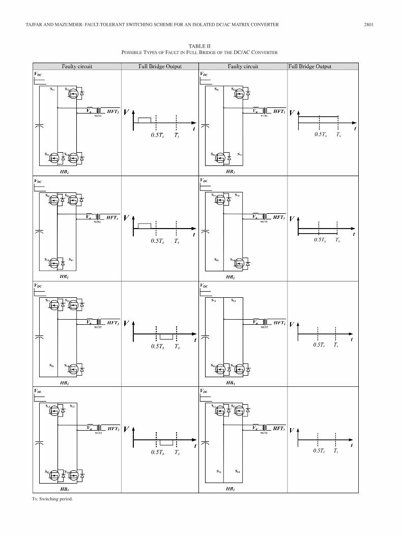
The term phase loss in this study is typically used for anykind of failure in full bridge switching devices that disruptsthe generation of bipolar HF pulses trains or distorts the outputline voltages. Table II illustrates different types of device fail-ure (leading to a short circuit between drain and source of the
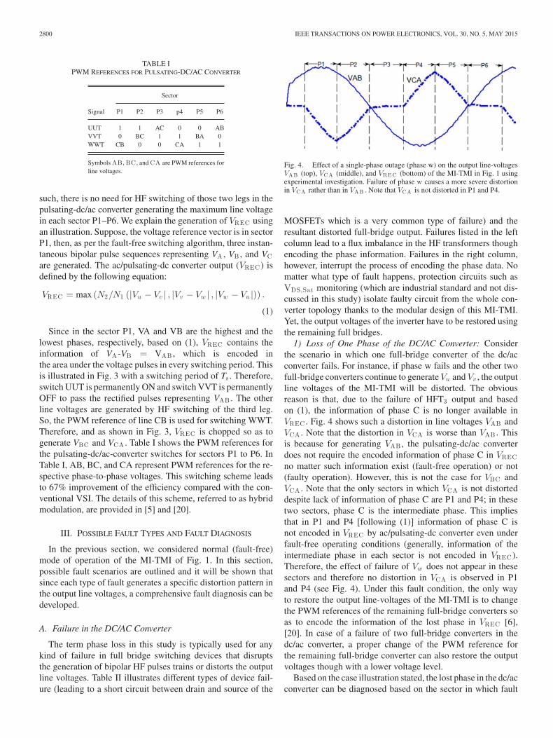
Fig. 4. Effect of a single-phase outage (phase w) on the output line-voltagesVAB (top), VCA (middle), and VREC (bottom) of the MI-TMI in Fig. 1 usingexperimental investigation. Failure of phase w causes a more severe distortionin VCA rather than in VAB . Note that VCA is not distorted in P1 and P4.
MOSFETs which is a very common type of failure) and theresultant distorted full-bridge output. Failures listed in the leftcolumn lead to a flux imbalance in the HF transformers thoughencoding the phase information. Failures in the right column,however, interrupt the process of encoding the phase data. Nomatter what type of fault happens, protection circuits such asVDS,Sat monitoring (which are industrial standard and not dis-cussed in this study) isolate faulty circuit from the whole con-verter topology thanks to the modular design of this MI-TMI.Yet, the output voltages of the inverter have to be restored usingthe remaining full bridges.
1) Loss of One Phase of the DC/AC Converter: Considerthe scenario in which one full-bridge converter of the dc/acconverter fails. For instance, if phase w fails and the other twofull-bridge converters continue to generate Vu and Vv , the outputline voltages of the MI-TMI will be distorted. The obviousreason is that, due to the failure of HFT3 output and basedon (1), the information of phase C is no longer available inVREC . Fig. 4 shows such a distortion in line voltages VAB andVCA . Note that the distortion in VCA is worse than VAB . Thisis because for generating VAB , the pulsating-dc/ac converterdoes not require the encoded information of phase C in VRECno matter such information exist (fault-free operation) or not(faulty operation). However, this is not the case for VBC andVCA . Note that the only sectors in which VCA is not distorteddespite lack of information of phase C are P1 and P4; in thesetwo sectors, phase C is the intermediate phase. This impliesthat in P1 and P4 [following (1)] information of phase C isnot encoded in VREC by ac/pulsating-dc converter even underfault-free operating conditions (generally, information of theintermediate phase in each sector is not encoded in VREC ).Therefore, the effect of failure of Vw does not appear in thesesectors and therefore no distortion in VCA is observed in P1and P4 (see Fig. 4). Under this fault condition, the only wayto restore the output line-voltages of the MI-TMI is to changethe PWM references of the remaining full-bridge converters soas to encode the information of the lost phase in VREC [6],[20]. In case of a failure of two full-bridge converters in thedc/ac converter, a proper change of the PWM reference forthe remaining full-bridge converter can also restore the outputvoltages though with a lower voltage level.
Based on the case illustration stated, the lost phase in the dc/acconverter can be diagnosed based on the sector in which fault
TAJFAR AND MAZUMDER: FAULT-TOLERANT SWITCHING SCHEME FOR AN ISOLATED DC/AC MATRIX CONVERTER 2801
TABLE IIPOSSIBLE TYPES OF FAULT IN FULL BRIDGE OF THE DC/AC CONVERTER
Ts: Switching period.
2802 IEEE TRANSACTIONS ON POWER ELECTRONICS, VOL. 30, NO. 5, MAY 2015
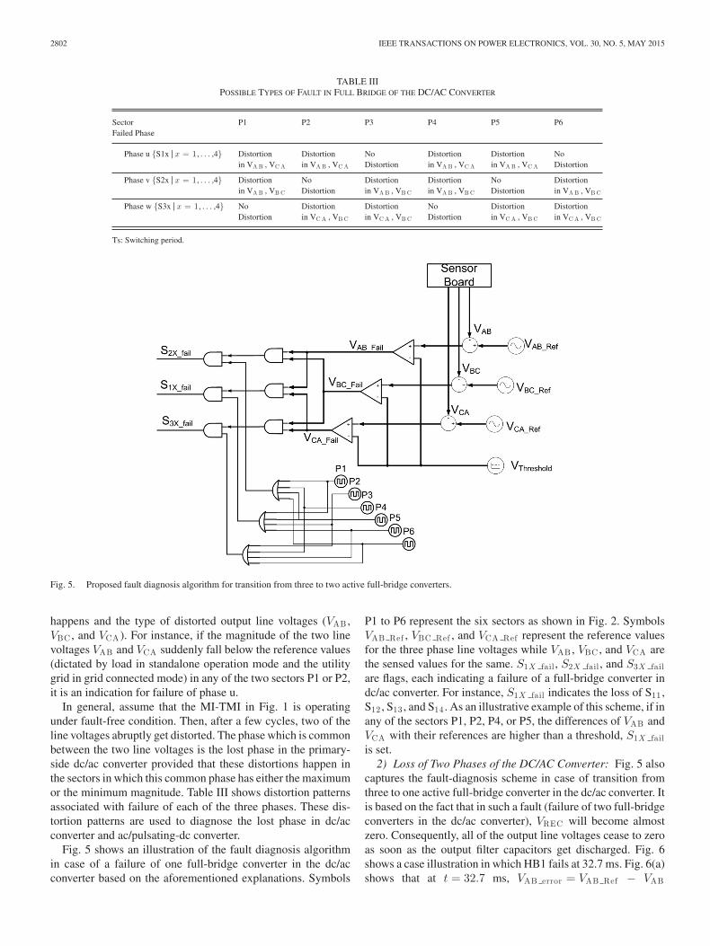
TABLE IIIPOSSIBLE TYPES OF FAULT IN FULL BRIDGE OF THE DC/AC CONVERTER
Sector P1 P2 P3 P4 P5 P6Failed Phase
Phase u {S1x | x = 1, . . . ,4} Distortion Distortion No Distortion Distortion Noin VA B , VC A in VA B , VC A Distortion in VA B , VC A in VA B , VC A Distortion
Phase v {S2x | x = 1, . . . ,4} Distortion No Distortion Distortion No Distortionin VA B , VB C Distortion in VA B , VB C in VA B , VB C Distortion in VA B , VB C
Phase w {S3x | x = 1, . . . ,4} No Distortion Distortion No Distortion DistortionDistortion in VC A , VB C in VC A , VB C Distortion in VC A , VB C in VC A , VB C
Ts: Switching period.
Fig. 5. Proposed fault diagnosis algorithm for transition from three to two active full-bridge converters.
happens and the type of distorted output line voltages (VAB ,VBC , and VCA ). For instance, if the magnitude of the two linevoltages VAB and VCA suddenly fall below the reference values(dictated by load in standalone operation mode and the utilitygrid in grid connected mode) in any of the two sectors P1 or P2,it is an indication for failure of phase u.
In general, assume that the MI-TMI in Fig. 1 is operatingunder fault-free condition. Then, after a few cycles, two of theline voltages abruptly get distorted. The phase which is commonbetween the two line voltages is the lost phase in the primary-side dc/ac converter provided that these distortions happen inthe sectors in which this common phase has either the maximumor the minimum magnitude. Table III shows distortion patternsassociated with failure of each of the three phases. These dis-tortion patterns are used to diagnose the lost phase in dc/acconverter and ac/pulsating-dc converter.
Fig. 5 shows an illustration of the fault diagnosis algorithmin case of a failure of one full-bridge converter in the dc/acconverter based on the aforementioned explanations. Symbols
P1 to P6 represent the six sectors as shown in Fig. 2. SymbolsVAB Ref , VBC Ref , and VCA Ref represent the reference valuesfor the three phase line voltages while VAB , VBC , and VCA arethe sensed values for the same. S1X fail , S2X fail , and S3X failare flags, each indicating a failure of a full-bridge converter indc/ac converter. For instance, S1X fail indicates the loss of S11 ,S12 , S13 , and S14 . As an illustrative example of this scheme, if inany of the sectors P1, P2, P4, or P5, the differences of VAB andVCA with their references are higher than a threshold, S1X failis set.
2) Loss of Two Phases of the DC/AC Converter: Fig. 5 alsocaptures the fault-diagnosis scheme in case of transition fromthree to one active full-bridge converter in the dc/ac converter. Itis based on the fact that in such a fault (failure of two full-bridgeconverters in the dc/ac converter), VREC will become almostzero. Consequently, all of the output line voltages cease to zeroas soon as the output filter capacitors get discharged. Fig. 6shows a case illustration in which HB1 fails at 32.7 ms. Fig. 6(a)shows that at t = 32.7 ms, VAB error = VAB Ref − VAB
TAJFAR AND MAZUMDER: FAULT-TOLERANT SWITCHING SCHEME FOR AN ISOLATED DC/AC MATRIX CONVERTER 2803
Fig. 6. (a) Top: VAB Ref (in blue) and VAB (in green) both normalized to phase voltage; middle: error signal (VAB Ref − VAB ), and bottom: S1x fail. Att = 32.7 ms, one of the bridges in the DC/AC converter corresponding to phase u fails and fault diagnosis logic in Fig. 6(a) activates S1x fail. Note that the faultis removed in less than 1 ms. (b) Same scenario is repeated with the exception that the fault is detected (see the jump in the error signal in the middle trace) but thefault is not restored intentionally in order to show the effect of full- bridge-converter loss on VAB .
TABLE IVINFORMATION ENCODED IN VREC FOR EACH OF THE SIX SECTORS P1–P6
Sector P1 P2 P3 P4 P5 P6Signal
VR E C Vuv Vuw Vvw Vvu Vwu Vwv
exceeds a threshold set in the fault diagnosis program (5%)and S1X fail is activated. It is shown that in less than 1 ms FTCcan restore the output line voltage VAB . Same scenario is re-peated in Fig. 6(b) in which FTC is not activated intentionallyin order to show the effect of HB1 loss on VAB .
B. Failure in the AC/Pulsating-DC Converter
If a switching device in a leg of ac/pulsating-dc converterfails, the distortion in the output line voltages is exactly similarto what happens if the corresponding full bridge (for the samephase) in the dc/ac converter fails. As such, the fault diagno-sis algorithm of Fig. 5 disables gate pulses to the MOSFETsof the leg associated with the diagnosed faulty phase in theac/pulsating-dc as well. For instance, if the fault diagnosis al-gorithm tracks a failure in phase u, gate pulses to UT and UBin the ac/pulsating-dc converter will be disabled upon diagnosisand PWM references for HB2 and HB3 will be changed as willbe explained in Section IV.
C. Failure in the Pulsating-DC/AC Converter
In order to facilitate our analysis, the content of VREC atdifferent sectors P1 to P6 is provided in Table IV at first. Forinstance, it shows that in sector P1, the pulse area of VRECat every switching period is equivalent to Vuv . The effect of a
MOSFET failure in dc/ac converter on the output line voltagesis analyzed through a case illustration in order to develop thefault diagnosis concept for such failures. Consider that while theMI-TMI of Fig. 1 is in fault-free operation, suddenly UUT fails(a short circuit between two of the three MOSFET terminals[21]). As a typical example, the effect of a short-circuit failurebetween drain and source terminals of MOSFETs on VREC aswell as on the output line voltages of the MI-TMI is shown inFig. 7. This fault occurs at t = 2 ms which falls in sector P1 . It isshown that before sector P3 , no distortion appears in the outputline voltages. The reason is as Table IV shows, in sectors P1 andP2 , the information of line voltages Vuv and Vuw is encoded inVREC and as shown previously in Table I, UUT is supposed toremain on in these sectors. However, it is observed that in P3since VVT turns on (according to hybrid modulation algorithm,Table V), VAB is zero and VBC = −VCA . Note that in P6 , VCAis zero and VAB = −VBC . In P3 and P6 , there are voltage spikesin VREC due to the fact that in these two sectors UUB starts HFswitching while UUT is shorted due to the fault.
By generalizing this analysis to other switching devices, afault-diagnosis algorithm for pulsating-dc/ac converter can bedeveloped as captured in Table V. Having analyzed all types offaults in three stages of the MI-TMI and proposed relevant faultdiagnosis algorithms, next section illustrates the fault-tolerantswitching scheme (FTSS) for this topology in details.
IV. FTSS FOR THE MI-TMI
Using the backdrop of the fault-free switching scheme, as ex-plained in Section II, and possible fault scenarios and diagnosisalgorithms in Section III, we now describe the FTSS for poten-tial switching device failure in all of the three stages. For dc/acconverter, the proposed FTSS restores three phase output line
2804 IEEE TRANSACTIONS ON POWER ELECTRONICS, VOL. 30, NO. 5, MAY 2015
Fig. 7. Effect of UUT failure on VREC and output line voltages of the MI-TMI of Fig. 1.
TABLE VFAULT AND DISTORTION PATTERNS FOR THE PULSATING-DC/AC CONVERTER
Sector P1 P2 P3 P4 P5 P6Failed MOSFET
UUT No No VA B = 0 No No VC A = 0Distortion Distortion VB C = −VC A Distortion Distortion VA B = −VB C
UUB No No VC A = 0 No No VA B = 0Distortion Distortion VA B = −VB C Distortion Distortion VB C = −VC A
VVT No VA B = 0 No No VB C = 0 NoDistortion VB C = −VC A Distortion Distortion VA B = −VC A Distortion
VVB No VB C = 0 No No VA B = 0 NoDistortion VA B = −VC A Distortion Distortion VB C = −VC A Distortion
WWT VC A = 0 No No VB C = 0 No NoVA B = −VB C Distortion Distortion VA B = −VC A Distortion Distortion
WWB VB C = 0 No No VC A = 0 No NoVA B = – VC A Distortion Distortion VA B = −VB C Distortion Distortion
voltages when one or even two phases of the dc/ac converterare lost. In essence, the fault-tolerant operation of the dc/acconverter ensures the synthesis of the same encoded pulsating-dc voltage (obtained during the fault-free operation) when oneor even two phases of the dc/ac converter are lost. In order togive an analytical insight into the FTSS, at first we considerthe equations for the output line-voltages of the MI-TMI un-der fault-free operation condition. For the MI-TMI of Fig. 1, thefollowing sets of equations are valid for the output line voltages:
VAB = (SUUT − SVVT) × VREC (2)
VBC = (SVVT − SWWT) × VREC (3)
VCA = (SWWT − SUUT) × VREC (4)
in which SUUT , SVVT , and SWWT are the switching functionsof the pulsating-dc/ac converter. However, we know that
where Sij (i, j = 1, 2, 3) is the switching functions of the dc/acconverter, VDC is the input dc voltage, and N1 and N2 are theprimary and the secondary turns ratio of the HF transform-ers, respectively. As mentioned earlier, if any one of the threefull-bridge converters of dc/ac converter fails, the encoded in-formation of the relevant phase in VREC is lost. For instance,if the full-bridge converter consisting of S31 , S32 , S33 , and S34fails, the information of phase C will no longer be encoded inVREC in sectors P2, P3, P5, and P6. Consequently, VREC willbe expressed as follows:
VREC =N2
N1× VDC × (|S11 − S21 | + |S13 − S23 |) . (6)
This in turn leads to a severe distortion in VBC and VCA and aslightly more moderate distortion in VAB . Fig. 4 shows the effectof loss of the full-bridge converter generating the information
TAJFAR AND MAZUMDER: FAULT-TOLERANT SWITCHING SCHEME FOR AN ISOLATED DC/AC MATRIX CONVERTER 2805
Fig. 8. PWM technique to retain the nominal operation in case of a single phase or a double-phase outage. If, for instance, phase w is lost, one of the remainedfull-bridge converters of the dc/ac converter generates a bipolar pulse train containing the information of the highest phase in every sector from P1–P6 while theother one does the same for the lowest phase.
of phase C on VAB and VCA (Note that a generalized analysisof loss of phases u, v, and w are given in Table III in context ofthe fault diagnosis). So, in order to restore the information ofthe lost phase, PWM references for the remaining full-bridgeconverters should be modified. In the subsequent sections, it willbe shown that this PWM reference modification is required foroutput line voltage restoration no matter in which stage a failureis occurred. The following sections discuss these modificationsunder different fault scenarios.
A. Case 1: FTSS Under Single-Phase Outageof the DC/AC Converter
If one of the phase outputs of the dc/ac converter is lost, thesignature of the VREC changes, which in turn affects the outputphase voltages. To generate the pulsating-dc voltage that hasthe same characteristic (or information content) as that obtainedunder fault-free operation, one of the remaining dc/ac converterfull-bridge converters has to generate a bipolar pulse train forthe highest phase while the other full-bridge converter has togenerate a bipolar pulse train for the lowest phase. “PWM1” and“PWM2” are two sets of four PWM signals which contain theinformation of the highest and the lowest phases in each sector if
any one of S1X fail , S2X fail , or S3X fail signals is 1 (see Fig. 8).Based on the diagnosed faulty phase in the dc/ac converter, theyare applied to the remaining full-bridge converters via a set oftwo demultiplexers “PWM DEMUX1” and “PWM DEMUX2.”For instance, if in any of the four sectors P1, P2, P4, or P5 thedifferences of VAB and VCA with their references are higherthan a threshold, S1X fail is set (see Fig. 5). Hence, PWM1 isconnected to the second full-bridge converter (S2X switches) viaPWM DEMUX1 and PWM2 is connected to the third one (S3Xswitches) via PWM DEMUX2. The result will be generation ofthe information of the highest phase by the second full-bridgeconverter and of the lowest phase by the third one in every sector.
B. Case 2: FTSS Under Double-Phase Outageof the DC/AC Converter
If two phases of the dc/ac converter are lost, the modulatingreference of the remaining full-bridge converter has to be mod-ified so as to encode the same information in the pulsating-dcvoltage (VREC ) as in fault-free operation. This information isnothing but the highest line voltage at each time. The mecha-nism to realize this FTSS is shown in Fig. 8. It shows that therequired PWM reference in each of the time sectors P1 to P6
2806 IEEE TRANSACTIONS ON POWER ELECTRONICS, VOL. 30, NO. 5, MAY 2015
TABLE VIPWM REFERENCES FOR THE DC/AC CONVERTER UNDER FAULT-FREE AND FAULT CONDITIONS FOR SECTORS P1–P6
Fig. 9. Failure in a phase of ac/pulsating-dc converter causes the same distortion in the output line voltages as if the same fault is lost in the dc/ac converter.Failure of phase c in the ac/pulsating converter causes a distortion pattern from which the fault diagnosis algorithm considers a fault in phase c of both converters.
is generated using the PWM reference for the highest line volt-age in that sector. Based on the diagnosed faulty phases in thedc/ac converter, the modified PWM is applied to the remainingfull-bridge converter via demultiplexer PWM DEMUX1. Forinstance, consider that both of the S1X fail and S3X fail signalsare set indicating that the only remained full-bridge converterin the dc/ac converter is the one consisting S21 , S22 , S23 , andS24 . Hence, the modified PWM is connected to the second full-bridge converter via PWM DEMUX1. The result will be gener-ation of the information of the highest line voltage by the secondfull-bridge converter in every sector. Table VI summarizes thePWM references for nominal operation, single- phase outage,and double phase outage.
C. Case 3: FTSS for Fault in the AC/Pulsating-DC Converter
As explained in Section III, if a leg of the ac/pulsating-dcconverter suddenly fails, it causes the same distortion pattern in
the output line voltages as resulted from a failure of the samephase in the dc/ac converter. It was also shown that for the samereason, the fault diagnosis algorithm for these two converters areequivalent and upon detection of a certain distortion pattern inthe output line voltages, a certain phase in both dc/ac converterand ac/pulsating-dc converter would be considered faulty. Asan example, assume that during fault-free operation, suddenlya MOSFET in the phase C fails. Since the protection circuitsof the module prevents firing of WT and WB (upon detectionof a short circuit in the leg consisting these switching devices),VREC will include only the information of phase A and phase B.As a result, output line voltages of the MI-TMI will be distortedaccording to the last row of Table III. This fault scenario isshown in Fig. 9. This specific distortion pattern in the outputline voltages is interpreted using the fault diagnosis algorithmof Fig. 5 as a failure of phase C in either dc/ac converter orac/pulsating-dc converter. The restoration steps are listed asfollows:
TAJFAR AND MAZUMDER: FAULT-TOLERANT SWITCHING SCHEME FOR AN ISOLATED DC/AC MATRIX CONVERTER 2807
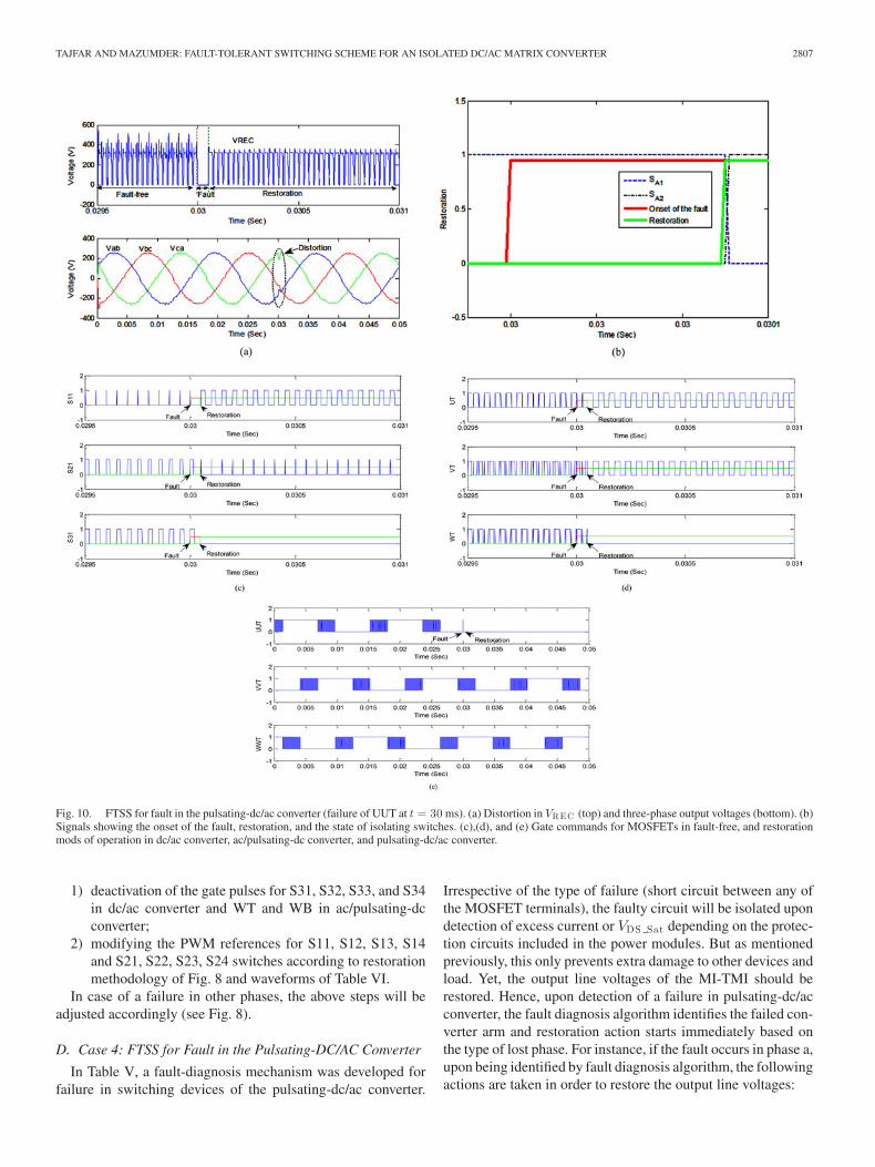
Fig. 10. FTSS for fault in the pulsating-dc/ac converter (failure of UUT at t = 30 ms). (a) Distortion in VREC (top) and three-phase output voltages (bottom). (b)Signals showing the onset of the fault, restoration, and the state of isolating switches. (c),(d), and (e) Gate commands for MOSFETs in fault-free, and restorationmods of operation in dc/ac converter, ac/pulsating-dc converter, and pulsating-dc/ac converter.
1) deactivation of the gate pulses for S31, S32, S33, and S34in dc/ac converter and WT and WB in ac/pulsating-dcconverter;
2) modifying the PWM references for S11, S12, S13, S14and S21, S22, S23, S24 switches according to restorationmethodology of Fig. 8 and waveforms of Table VI.
In case of a failure in other phases, the above steps will beadjusted accordingly (see Fig. 8).
D. Case 4: FTSS for Fault in the Pulsating-DC/AC Converter
In Table V, a fault-diagnosis mechanism was developed forfailure in switching devices of the pulsating-dc/ac converter.
Irrespective of the type of failure (short circuit between any ofthe MOSFET terminals), the faulty circuit will be isolated upondetection of excess current or VDS Sat depending on the protec-tion circuits included in the power modules. But as mentionedpreviously, this only prevents extra damage to other devices andload. Yet, the output line voltages of the MI-TMI should berestored. Hence, upon detection of a failure in pulsating-dc/acconverter, the fault diagnosis algorithm identifies the failed con-verter arm and restoration action starts immediately based onthe type of lost phase. For instance, if the fault occurs in phase a,upon being identified by fault diagnosis algorithm, the followingactions are taken in order to restore the output line voltages:
2808 IEEE TRANSACTIONS ON POWER ELECTRONICS, VOL. 30, NO. 5, MAY 2015
Fig. 11. Illustration of the overall fault diagnosis algorithm and FTSS for an isolated and multistage MI-TMI.
1) S_A1 and S_T3 will be opened;2) S_A2 is closed;3) PWM commands for UUT and UUB are applied to WT
and WB, respectively;4) PWM signals for {S1X , x = 1, . . . ,4} and {S2X , x =
1, . . . ,4} are changed as in the case if phase w is lost inthe dc/ac converter (see Table VI). Also, PWM signals for{S3X , x = 1, . . . ,4} are disabled;
5) PWM commands for UT, UB, VT, and VB are changedas in the case if phase w is lost in the ac/pulsating-dcconverter (see Table VI).
Fig. 10 demonstrates the simulation results of a failure inUUT. At t = 30 ms, due to a fault, a short circuit happens be-tween drain and source of UUT. Protection logic disables gatecommands for this leg (consisting of UUT and UUB) and theabove steps are initiated. Restoration algorithm changes the gate
TAJFAR AND MAZUMDER: FAULT-TOLERANT SWITCHING SCHEME FOR AN ISOLATED DC/AC MATRIX CONVERTER 2809
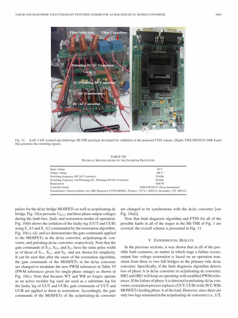
Fig. 12. (Left) 1-kW isolated and multistage MI-TMI prototype developed for validation of the proposed FTSS scheme. (Right) TMS320F28335 DSK boardthat generates the switching signals.
TABLE VIIPHYSICAL SPECIFICATIONS OF THE INVERTER PROTOTYPE
Input voltage 40 VOutput voltage 208 VSwitching frequency (DC/AC Converter) 20 kHzSwitching frequency (AC/Pulsating-DC, Pulsating-DC/AC Converter) 40 kHzRated power 1000 WController board TMS320F28335 (Texas Instrument)Transformers: Nanocrystalline core (MK Magnetics # STX1060M1), Primary: 12T 6 x AWG14, Secondary: 52T AWG14
pulses for the dc/ac bridge MOSFETs as well as ac/pulsating-dcbridge. Fig. 10(a) presents VREC and three phase output voltagesduring the fault-free, fault, and restoration modes of operation.Fig. 10(b) shows the isolation of the faulty leg (UUT and UUB)using S_A1 and S_A2 commanded by the restoration algorithm.Fig. 10(c), (d), and (e) demonstrates the gate commands appliedto the MOSFETs in the dc/ac converter, ac/pulsating-dc con-verter, and pulsating-dc/ac converter, respectively. Note that thegate commands of S13 , S23 , and S33 have the same pulse widthas of those of S11 , S21 , and S31 and not shown for simplicity.It can be seen that after the onset of the restoration algorithm,the gate commands of the MOSFETs in the dc/ac converterare changed to modulate the new PWM references in Table VI(PWM references given for single-phase outage) as shown inFig. 10(c). Note that because WT and WB no longer operateas an active rectifier leg (and are used as a substitute leg forthe faulty leg of UUT and UUB), gate commands of UUT andUUB are applied to them in restoration. Accordingly, the gatecommands of the MOSFETs of the ac/pulsating-dc converter
are changed to be synchronous with the dc/ac converter [seeFig. 10(d)].
Now that fault diagnosis algorithm and FTSS for all of thepossible faults in all of the stages in the MI-TMI of Fig. 1 arecovered, the overall scheme is presented in Fig. 11.
V. EXPERIMENTAL RESULTS
In the previous sections, it was shown that in all of the pos-sible fault scenarios, no matter in which stage a failure occurs,output line voltage restoration is based on an operation tran-sition from three to two full bridges in the primary-side dc/acconverter. Specifically, if the fault diagnosis algorithm detectsloss of phase A in dc/ac converter or ac/pulsating-dc converter,HB2 and HB3 will keep on operating with modified PWM refer-ences. If the failure of phase A is detected in pulsating-dc/ac con-verter, restoration process replaces (UUT, UUB) with (WT, WB)MOSFETs feeding phase A of the load. However, since there areonly two legs remained in the ac/pulsating-dc converter (i.e., UT,
2810 IEEE TRANSACTIONS ON POWER ELECTRONICS, VOL. 30, NO. 5, MAY 2015
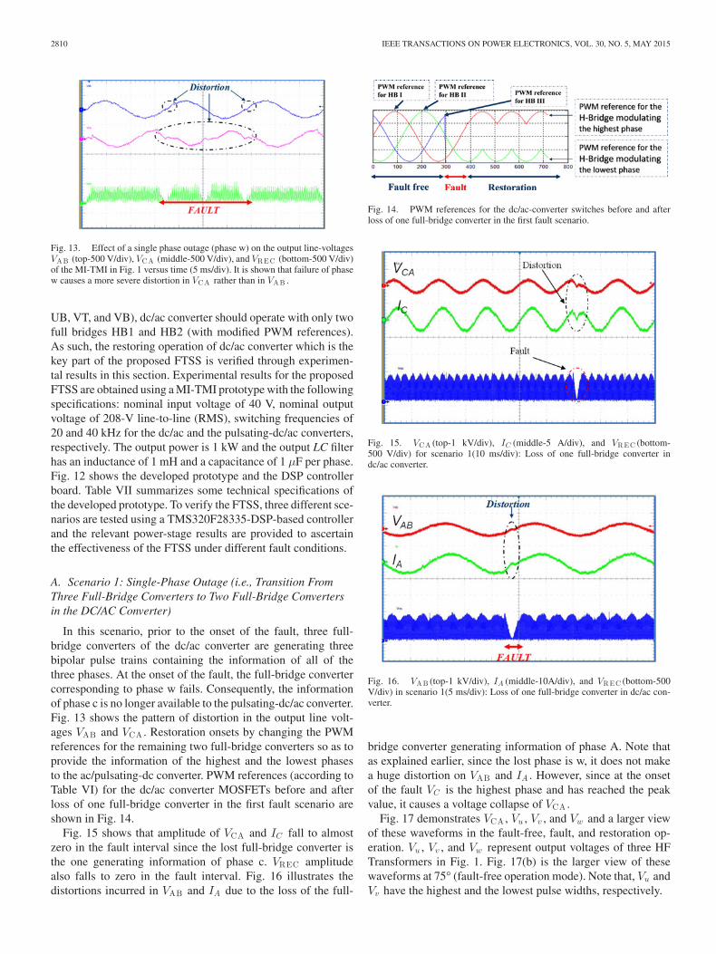
Fig. 13. Effect of a single phase outage (phase w) on the output line-voltagesVAB (top-500 V/div), VCA (middle-500 V/div), and VREC (bottom-500 V/div)of the MI-TMI in Fig. 1 versus time (5 ms/div). It is shown that failure of phasew causes a more severe distortion in VCA rather than in VAB .
UB, VT, and VB), dc/ac converter should operate with only twofull bridges HB1 and HB2 (with modified PWM references).As such, the restoring operation of dc/ac converter which is thekey part of the proposed FTSS is verified through experimen-tal results in this section. Experimental results for the proposedFTSS are obtained using a MI-TMI prototype with the followingspecifications: nominal input voltage of 40 V, nominal outputvoltage of 208-V line-to-line (RMS), switching frequencies of20 and 40 kHz for the dc/ac and the pulsating-dc/ac converters,respectively. The output power is 1 kW and the output LC filterhas an inductance of 1 mH and a capacitance of 1 μF per phase.Fig. 12 shows the developed prototype and the DSP controllerboard. Table VII summarizes some technical specifications ofthe developed prototype. To verify the FTSS, three different sce-narios are tested using a TMS320F28335-DSP-based controllerand the relevant power-stage results are provided to ascertainthe effectiveness of the FTSS under different fault conditions.
A. Scenario 1: Single-Phase Outage (i.e., Transition FromThree Full-Bridge Converters to Two Full-Bridge Convertersin the DC/AC Converter)
In this scenario, prior to the onset of the fault, three full-bridge converters of the dc/ac converter are generating threebipolar pulse trains containing the information of all of thethree phases. At the onset of the fault, the full-bridge convertercorresponding to phase w fails. Consequently, the informationof phase c is no longer available to the pulsating-dc/ac converter.Fig. 13 shows the pattern of distortion in the output line volt-ages VAB and VCA . Restoration onsets by changing the PWMreferences for the remaining two full-bridge converters so as toprovide the information of the highest and the lowest phasesto the ac/pulsating-dc converter. PWM references (according toTable VI) for the dc/ac converter MOSFETs before and afterloss of one full-bridge converter in the first fault scenario areshown in Fig. 14.
Fig. 15 shows that amplitude of VCA and IC fall to almostzero in the fault interval since the lost full-bridge converter isthe one generating information of phase c. VREC amplitudealso falls to zero in the fault interval. Fig. 16 illustrates thedistortions incurred in VAB and IA due to the loss of the full-
Fig. 14. PWM references for the dc/ac-converter switches before and afterloss of one full-bridge converter in the first fault scenario.
Fig. 15. VCA (top-1 kV/div), IC (middle-5 A/div), and VREC (bottom-500 V/div) for scenario 1(10 ms/div): Loss of one full-bridge converter indc/ac converter.
Fig. 16. VAB (top-1 kV/div), IA (middle-10A/div), and VREC (bottom-500V/div) in scenario 1(5 ms/div): Loss of one full-bridge converter in dc/ac con-verter.
bridge converter generating information of phase A. Note thatas explained earlier, since the lost phase is w, it does not makea huge distortion on VAB and IA . However, since at the onsetof the fault VC is the highest phase and has reached the peakvalue, it causes a voltage collapse of VCA .
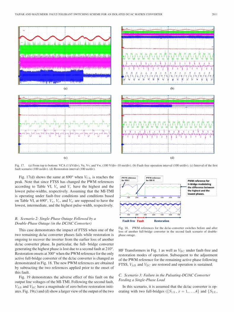
Fig. 17 demonstrates VCA , Vu , Vv , and Vw and a larger viewof these waveforms in the fault-free, fault, and restoration op-eration. Vu , Vv , and Vw represent output voltages of three HFTransformers in Fig. 1. Fig. 17(b) is the larger view of thesewaveforms at 75° (fault-free operation mode). Note that, Vu andVv have the highest and the lowest pulse widths, respectively.
TAJFAR AND MAZUMDER: FAULT-TOLERANT SWITCHING SCHEME FOR AN ISOLATED DC/AC MATRIX CONVERTER 2811
Fig. 17. (a) From top to bottom: VCA (1 kV/div), Vu, Vv, and Vw, (100 V/div–10 ms/div). (b) Fault-free operation interval (100 us/div). (c) Interval of the firstfault scenario (100 us/div). (d) Restoration interval (100 us/div).
Fig. 17(d) shows the same at 690° when VCA is reaches thepeak. Note that since FTSS has changed the PWM referencesaccording to Table VI, Vu and Vv have the highest and thelowest pulse-widths, respectively. Assuming that the MI-TMIis operating under fault-free conditions and conditions basedon Table VI, at 690°, Vu , Vv , and Vw are supposed to have thelowest, intermediate, and the highest pulse-width, respectively.
B. Scenario 2: Single-Phase Outage Followed by aDouble-Phase Outage (in the DC/AC Converter)
This case demonstrates the impact of FTSS when one of thetwo remaining dc/ac converter phases fails while restoration isongoing to recover the inverter from the earlier loss of anotherdc/ac converter phase. In particular, the full- bridge convertergenerating the highest phase is lost due to a second fault at 210°.Restoration onsets at 300°when the PWM reference for the onlyactive full-bridge converter of the dc/ac converter is changed asdemonstrated in Fig. 18. The new PWM references are obtainedby subtracting the two references applied prior to the onset ofthis fault.
Fig. 19 demonstrates the adverse effect of this fault on theoutput line voltages of the MI-TMI. Following the second fault,VAB and VBC have a magnitude of zero before restoration initi-ates. Fig. 19(c) and (d) show a larger view of the output of the two
Fig. 18. PWM references for the dc/ac-converter switches before and afterloss of another full-bridge converter in the second fault scenario of double-phase outage.
HF Transformers in Fig. 1 as well as VBC under fault-free andrestoration modes of operation. Subsequent to the adjustmentof the PWM reference for the remaining active phase followingFTSS, VAB and VBC are restored and operation is sustained.
C. Scenario 3: Failure in the Pulsating-DC/AC ConverterFeeding a Single-Phase Load
In this scenario, it is assumed that the dc/ac converter is op-erating with two full-bridges ({S1X , x = 1, . . . ,4} and {S2X ,
2812 IEEE TRANSACTIONS ON POWER ELECTRONICS, VOL. 30, NO. 5, MAY 2015
Fig. 19. Fault scenario 2: double-phase outage. (a) VAB (1 kV/div–10 ms/div). (b) From top to bottom: VBC (1kV/div—10 ms/div), signal indicating theonset of failure of one of the dc/ac converter phases at rising edge, and the onset of fault-tolerant control action at the trailing edge. Larger view of Vu , and Vv
(100 V/div–100 us/div) are shown in (c) fault-free operation and (d) restoration interval.
Fig. 20. Fault scenario 3: FTSS for the pulsating-dc/ac converter operatingunder single phase load. From top to bottom: output phase voltage (144 V/div–5 ms/div), PWM signals for pulsating-dc/ac converter switching devices.
x = 1, . . . ,4}) and consequently (WT, WB) are not switching.Pulsating-dc/ac Converter is feeding a single-phase load con-nected to the legs containing UUT, UUB, VVT, and VVB. Sud-denly, a failure in the leg of VVT, VVB leads to isolation of
this leg and interruption of the service. The fault is generatedby deliberately turning on the high-side MOSFET (VVT) whileUUT is on leading to a sag in the output voltage. Restorationalgorithm opens S_B1 and closes S_B2 and also applies thePWM pulses of VVT and VVB to WT and WB so that the out-put phase voltage is restored. Fig. 20 shows the result of thisscenario. The top trace, shows the output phase voltage and therest of the traces from top to bottom are PWM pulses for UUT,VVT, and WT. Note that since VREC encodes the information ofthe output phase voltage, Pulsating-dc/ac converter only needsto fold it with respect to positive and negative half cycles usinglow frequency PWM signals. It is shown that at the onset of thefault, both UUT and VVT are turned on and the output voltagefalls to zero but FTSS replaces the lost leg of VVT and VVBwith the redundant leg consisting of WT and WB in the activerectifier and restores the output phase voltage.
VI. CONCLUSION
A novel FTSS is proposed for all of the three stages in aMI-TMI. The proposed FTSS is designed based on the inherentredundancy of one phase in the primary side dc/ac converterand ac/pulsating-dc converter and is based on changing thePWM references for the remaining full-bridge converters upon
TAJFAR AND MAZUMDER: FAULT-TOLERANT SWITCHING SCHEME FOR AN ISOLATED DC/AC MATRIX CONVERTER 2813
detection of the fault using a proposed fault diagnosis system.The new switching scheme provides the continuity of serviceof the inverter while maintaining acceptable dc-link and out-put voltages when one or even two phases of the dc/ac con-verter ceases to generate any output, or when one phase inac/pulsating-dc converter or pulsating-dc/ac converter fails. Ef-fect of the time (or phase angle) at which a fault happens wasdiscussed and based on a comprehensive analysis of the latter afault diagnosis algorithm is proposed. In the diagnosis step, thedistortion pattern of the three line voltages VAB , VBC , and VCAare diagnosed. As explained in Section III of this paper, by ana-lyzing the pattern of distortion in each of the three line voltageswith six sectors, we can determine the lost phase and the faultystage. In the next step, based on the type of lost phase(s) andfaulty stage, the PWM reference for the remaining phase(s) ischanged so as to restore the output line voltages of the inverter.The effectiveness of the FTSS under various fault scenarios wasinvestigated through experimental results on a 1-kW prototypeand found to be satisfactory.
REFERENCES
[1] L. Empringham, J. W. Kolar, J. Rodriguez, P. W. Wheeler, and J. C. Clare,“Technological issues and industrial application of matrix converters: Areview,” IEEE Trans. Ind. Electron., vol. 60, no. 10, pp. 4260–4271,Oct. 2013.
[2] K. Basu, R. K. Gupta, S. Nath, and G. F. Castelino, “Research in matrix-converter based three-phase power-electronic transformers,” in Proc. Int.Power Electron. Conf., 2010, pp. 299–2803.
[3] S. Manias, P. D. Ziogas, and G. Olivier, “Bilateral dc to ac convertor usinga high frequency link,” Proc. IEE, vol. 134, no. 1, pp. 15–23, Feb. 1987.
[4] M. Koyama, K. Sanada, N. Sashida, and T. Kawabata, “High frequencylink dc/ac converter with PWM cycloconverter for UPS,” in Proc. Int.Power Electron. Conf., 1990, pp. 748–754.
[5] S. K. Mazumder, “A novel hybrid modulation scheme for an isolatedhigh-frequency-link fuel cell inverter,” in Proc. IEEE Power Energy Soc.Gen. Meeting, 2008, pp. 1–7.
[6] P. Barriuso, J. Dixon, P. Flores, and L. Moran, “Fault tolerant reconfig-uration system for asymmetric multilevel converters using bi-directionalpower switches,” IEEE Trans. Ind. Electron., vol. 56, no. 4, pp. 1300–1306,Apr. 2009.
[7] A. Tajfar and S. K. Mazumder, “A fault-tolerant switching scheme fora photovoltaic high-frequency-link inverter,” in Proc. IEEE Appl. PowerElectron. Conf. Expo., 2012, pp. 2087–2094.
[8] A. Tajfar and S. K. Mazumder, “A transformer-flux-balance controller fora high-frequency-link inverter,” in Proc. IEEE Elect. Ship Technol. Symp.,2011, pp. 121–126.
[9] A. Rahnamaee and S. K. Mazumder, “A soft-switching modulationscheme for a three-phase capacitor-less pulsating-dc link transformer-isolated inverter,” IEEE Trans. Power Electron., vol. 29, no. 8, pp. 3893–3906, 2014.
[10] A. Tajfar and S. K. Mazumder, “Control of high-frequency-link inverterusing optimal switching sequence,” in Proc. IEEE Energy Convers. Conf.Expo., 2012, pp. 4703–4710.
[11] A. Tajfar and S. K. Mazumder, “An optimal sequence-based-controller(OSBC) for a grid-connected three-phase photovoltaic high-frequency-link inverter,” in Proc. IEEE Appl. Power Electron. Conf., 2013, pp. 905–911.
[12] S. K. Mazumder and K. Acharya, “Multiple Lyapunov function basedreaching criteria for orbital existence of switching power converters,”IEEE Trans. Power Electron., vol. 23, no. 3, pp. 1449–1471, 2008.
[13] Z. Sang, C. Mao, J. Lu, and D. Wang, “Analysis and simulation of faultcharacteristics of power switch failures in distribution electronic powertransformers,” Energies, vol. 6, pp. 4246–4268, 2013.
[14] A. Gaillard, S. Karimi, P. Poure, S. Saadate, and E. Gholipour, “A faulttolerant converter topology for wind energy conversion system with dou-bly fed induction generator,” in Proc. Eur. Conf. Power Electron. Appl.,Sep. 2007, pp. 1–6.
[15] R. R. Errabelli and P. Mutschler, “Fault-tolerant voltage source inverterfor permanent magnet drives,” IEEE Trans. Power Electron., vol. 27,no. 2, pp. 500–508, Feb. 2012.
[16] Y. Song and B. Wang, “Analysis and experimental verification of a fault-tolerant HEV powertrain,” IEEE Trans. Power Electron., vol. 28, no. 12,pp. 5854–5864, Dec. 2013.
[17] W. Wang, M. Cheng, B. Zhang, Y. Zhu, and S. Ding, “A fault-tolerantpermanent-magnet traction module for subway applications,” IEEE Trans.Power Electron., vol. 29, no. 4, pp. 1646–1658, Apr. 2014.
[18] S.-M. Jung, J.-S. Park, H.-W. Kim, K.-Y. Cho, and M.-J. Youn, “A MRAS-based diagnosis of open-circuit fault in PWM voltage-source inverters forPM synchronous motor drive systems,” IEEE Trans. Power Electron.,vol. 28, no. 5, pp. 2514–2526, May 2013.
[19] U.-M. Choi, H.-G. Jeong, K.-B. Lee, and F. Blaabjerg, “Method for de-tecting an open-switch fault in a grid-connected NPC inverter system,”IEEE Trans. Power Electron., vol. 27, no. 6, pp. 2726–2739, Jun. 2012.
[20] S. K. Mazumder and R. Huang, “Multiphase converter apparatus andmethod,” U.S. Patent 7 ,768 ,800 B2, Aug. 3, 2010.
[21] NXP Semiconductors, “Application note AN11243: Failure signature ofelectrical overstress on power MOSFETs,” Rev. 01, Oct. 29, 2012.
Alireza Tajfar (S’10) received the B.Sc. degree inelectronics engineering from the Petroleum Instituteof Technology, Ahwaz, Iran, in 2002, and the M.Sc.degree in electrical engineering from the Iran Uni-versity of Science and Technology, Tehran, Iran, in2005, and the Ph.D. degree in electrical engineeringfrom the University of Illinois, Chicago, IL, USA, in2014.
He is currently a Senior Power Electronic Engi-neer at Enphase Energy developing high-frequencymicroinverters used in solar energy applications. He
has published more than ten refereed international conference papers. His re-search interests include power electronics for renewable and alternate energysources, and modeling, analysis, and control of high-frequency-link power in-verters.
Dr. Tajfar is a Reviewer for the IEEE TRANSACTIONS ON POWER ELEC-TRONICS, the IEEE TRANSACTIONS ON INDUSTRIAL ELECTRONICS, and severalinternational conferences.
Sudip K. Mazumder (S’97–M’01–SM’03) receivedthe Ph.D. degree in electrical and computer engineer-ing from Virginia Tech, Blacksburg, VA, USA, in2001.
He is currently a Professor at the Departmentof Electrical and Computer Engineering, Universityof Illinois at Chicago (UIC), Chicago, IL, USA. Hehas 22 years of professional experience and has heldR&D and design positions in leading industrial or-ganizations and served as a consultant for several in-dustries. He also serves as the President of NextWatt
LLC since 2008. Since joining UIC, he has been awarded about 40 sponsoredprojects by leading U.S. federal research organizations and industries. He haspublished more than 180 journal and conference papers and nine books/bookchapters, presented more than 60 invited presentations, and holds eight issuedand several pending patents.
Dr. Mazumder serves as the Guest Editor-in-Chief and as an Associate Editorof multiple IEEE transactions and was the first Editor-in-Chief for Advancesin Power Electronics. He has served and is serving in high-profile capacitieson leading PELS Conference TPCs, PELS TCs, IEEE Working Group, andhigh-profile NSF panels. He has received several prestigious awards includingthe University of Illinois Chicago’s Inventor of the Year Award, University ofIllinois’ University Scholar Award, IEEE PELS Transaction Prize Paper Award,IEEE Future Energy Challenge Award, ONR Young Investigator Award, andNSF CAREER Award.