28 Series resonance and Q-factor At the end of this chapter you should be able to: ž state the conditions for resonance in an a.c. series circuit ž calculate the resonant frequency in an a.c. series circuit, f r D 1 2p LC ž define Q-factor as X R and as V L V or V C V ž determine the maximum value of V C and V COIL and the frequency at which this occurs ž determine the overall Q-factor for two components in series ž define bandwidth and selectivity ž calculate Q-factor and bandwidth in an a.c. series circuit ž determine the current and impedance when the frequency deviates from the resonant frequency 28.1 Introduction When the voltage V applied to an electrical network containing resistance, inductance and capacitance is in phase with the resulting current I, the circuit is said to be resonant. The phenomenon of resonance is of great value in all branches of radio, television and communications engineering, since it enables small portions of the communications frequency spectrum to be selected for amplification independently of the remainder. At resonance, the equivalent network impedance Z is purely resistive since the supply voltage and current are in phase. The power factor of a resonant network is unity,(i.e., power factor D cos D cos 0 D 1). In electrical work there are two types of resonance — one associated with series circuits,(which was introduced in Chapter 15), when the input impedance is a minimum, (which is discussed further in this chapter), and the other associated with simple parallel networks, when the input impedance is a maximum (which is discussed in Chapter 29). 28.2 Series resonance Figure 28.1 shows a circuit comprising a coil of inductance L and resis- tance R connected in series with a capacitor C. The R – L – C series circuit has a total impedance Z given by Z D R C jX L X C ) ohms, or Z D mywbut.com 1
Transcript
28 Series resonance andQ-factor
At the end of this chapter you should be able to:
ž state the conditions for resonance in an a.c. series circuit
ž calculate the resonant frequency in an a.c. series circuit,
fr D 1
2pLC
ž define Q-factor asX
Rand as
VL
Vor
VC
V
ž determine the maximum value of VC and VCOIL and thefrequency at which this occurs
ž determine the overall Q-factor for two components in series
ž define bandwidth and selectivity
ž calculate Q-factor and bandwidth in an a.c. series circuit
ž determine the current and impedance when the frequencydeviates from the resonant frequency
28.1 Introduction When the voltage V applied to an electrical network containing resistance,inductance and capacitance is in phase with the resulting current I, thecircuit is said to be resonant. The phenomenon of resonance is of greatvalue in all branches of radio, television and communications engineering,since it enables small portions of the communications frequency spectrumto be selected for amplification independently of the remainder.
At resonance, the equivalent network impedance Z is purely resistivesince the supply voltage and current are in phase. The power factor of aresonant network is unity,(i.e., power factor D cos D cos 0 D 1).
In electrical work there are two types of resonance — one associatedwith series circuits,(which was introduced in Chapter 15), when the inputimpedance is a minimum, (which is discussed further in this chapter),and the other associated with simple parallel networks, when the inputimpedance is a maximum (which is discussed in Chapter 29).
28.2 Series resonance Figure 28.1 shows a circuit comprising a coil of inductance L and resis-tance R connected in series with a capacitor C. The R–L–C series circuithas a total impedance Z given by Z D R C jXL XC) ohms, or Z D
mywbut.com
1
Figure 28.1 R L C seriescircuit
R C jωL 1/ωC ohms where ω D 2f. The circuit is at resonancewhen XL XC D 0, i.e., when XL D XC or ωL D 1/ωC. The phasordiagram for this condition is shown in Figure 28.2, where jVLj D jVCj.
Since at resonance ωrL D 1
ωrC, ω2
r D 1
LCand ω D 1p
LC
Thus resonant frequency, fr =1
2pp
.LC /hertz, since ωr D 2fr
Figure 28.2 Phasor diagramjVLj D jVCj
Figure 28.3 shows how inductive reactance XL and capacitive reactanceXC vary with the frequency. At the resonant frequency fr , jXLj D jXCj.Since impedance Z D R C jXL XC and, at resonance, XL XC D0, then impedance Z = R at resonance. This is the minimum valuepossible for the impedance as shown in the graph of the modulus ofimpedance, jZj, against frequency in Figure 28.4.
Figure 28.3 Variation ofXL andXC with frequency
At frequencies less than fr , XL < XC and the circuit is capacitive; atfrequencies greater than fr , XL > XC and the circuit is inductive.
Current I D V/Z. Since impedance Z is a minimum value at resonance,the current I has a maximum value. At resonance, current I D V/R. Agraph of current against frequency is shown in Figure 28.4.
Problem 1. A coil having a resistance of 10 and an inductanceof 75 mH is connected in series with a 40 µF capacitor across a200 V a.c. supply. Determine at what frequency resonance occurs,and (b) the current flowing at resonance.
mywbut.com
2
Figure 28.4 jZj and I plotted against frequency
(a) Resonant frequency,
fr D 1
2pLC
D 1
2√
[75 ð 10340 ð 106]
i.e., fr = 91.9 Hz
(b) Current at resonance, I D V
RD 200
10D 20 A
Problem 2. An R–L–C series circuit is comprised of a coil ofinductance 10 mH and resistance 8 and a variable capacitor C.The supply frequency is 1 kHz. Determine the value of capacitorC for series resonance.
At resonance, ωrL D 1/ωrC, from which, capacitance, C D 1/ω2r L
Hence capacitance C D 1
21000210 ð 103D 2.53 mF
Problem 3. A coil having inductance L is connected in series witha variable capacitor C. The circuit possesses stray capacitance CS
which is assumed to be constant and effectively in parallel withthe variable capacitor C. When the capacitor is set to 1000 pFthe resonant frequency of the circuit is 92.5 kHz, and when thecapacitor is set to 500 pF the resonant frequency is 127.8 kHz.Determine the values of (a) the stray capacitance CS, and (b) thecoil inductance L.
mywbut.com
3
For a series R–L–C circuit the resonant frequency fr is given by:
fr D 1
2pLC
The total capacitance of C in parallel with CS is given by C C CS
At 92.5 kHz, C D 1000 pF. Hence
92.5 ð 103 D 1
2√
[L1000 C CS1012]1
At 127.8 kHz, C D 500 pF. Hence
127.8 ð 103 D 1
2√
[L500 C CS1012]2
(a) Dividing equation (2) by equation (1) gives:
127.8 ð 103
92.5 ð 103D
1
2√
[L500 C CS1012]1
2√
[L1000 C CS1012]
i.e.,127.8
92.5D
√[L1000 C CS1012]√[L500 C CS1012]
D√(
1000 C CS
500 C CS
)
where CS is in picofarads, from which,
(127.8
92.5
)2
D 1000 C CS
500 C CS
i.e., 1.909 D 1000 C CS
500 C CS
Hence 1.909500 C CS D 1000 C CS
954.5 C 1.909CS D 1000 C CS
1.909CS CS D 1000 954.5
0.909CS D 45.5
Thus stray capacitance CS D 45.5/0.909 D 50 pF
(b) Substituting CS D 50 pF in equation (1) gives:
92.5 ð 103 D 1
2√
[L1050 ð 1012]
mywbut.com
4
Hence 92.5 ð 103 ð 22 D 1
L1050 ð 1012
from which, inductance L D 1
1050 ð 101292.5 ð 103 ð 22H
D 2.82 mH
Furtherproblems on series resonance may be found in Section 28.8, prob-lems 1 to 5, page 512
28.3 Q-factor Q-factor is a figure of merit for a resonant device such as an L–C–Rcircuit.
Such a circuit resonates by cyclic interchange of stored energy, accom-panied by energy dissipation due to the resistance.
By definition, at resonance Q D 2(
maximum energy stored
energy loss per cycle
)
Since the energy loss per cycle is equal to (the average power dissipated)ð (periodic time),
Q D 2(
maximum energy stored
average power dissipated ð periodic time
)
D 2(
maximum energy stored
average power dissipated ð 1/fr
)
since the periodic time T D 1/fr .
Thus Q D 2fr
(maximum energy stored
average power dissipated
)
i.e., Q D ωr
(maximum energy stored
average power dissipated
)
where ωr is the angular frequency at resonance.In an L–C–R circuit both of the reactive elements store energy during
a quarter cycle of the alternating supply input and return it to the circuitsource during the following quarter cycle. An inductor stores energy inits magnetic field, then transfers it to the electric field of the capacitorand then back to the magnetic field, and so on. Thus the inductive andcapacitive elements transfer energy from one to the other successivelywith the source of supply ideally providing no additional energy at all.Practical reactors both store and dissipate energy.
Q-factor is an abbreviation for quality factor and refers to the ‘good-ness’ of a reactive component.
mywbut.com
5
For an inductor, Q D ωr
(maximum energy stored
average power dissipated
)
D ωr
(12LI
2m
I2R
)D
ωr
(12LI
2m
)
Im/p
22RD ωrL
R28.1
For a capacitor Q Dωr
(12CV
2m
)
Im/p
22RD ωr
12CImXC2
Im/p
22R
D ωr12CI
2m1/ωrC2
Im/p
22R
i.e., Q D 1
ωrCR28.2
From expressions (28.1) and (28.2) it can be deduced that
Q D XL
RD XC
RD reactance
resistance
In fact, Q-factor can also be defined as
Q-factor D reactance power
resistanceD Q
P
where Q is the reactive power which is also the peak rate of energystorage, and P is the average energy dissipation rate. Hence
Q-factor D Q
PD I2XLor I2XC
I2RD XL
R
(or
XC
R
)
i.e., Q =reactanceresistance
In an R–L–C series circuit the amount of energy stored at resonance isconstant.
When the capacitor voltage is a maximum, the inductor current is zero,and vice versa, i.e., 1
2LI2m D 1
2CV2m
Thus the Q-factor at resonance, Qr is given by
Qr =!r LR
=1
!r CR28.3
However, at resonance ωr D 1/pLC
Hence Qr D ωrL
RD 1p
LC
(L
R
)i.e, Qr =
1R
√(L
C
)
mywbut.com
6
It should be noted that when Q-factor is referred to, it is nearly alwaysassumed to mean ‘the Q-factor at resonance’.
With reference to Figures 28.1 and 28.2, at resonance, VL D VC
VL D IXL D IωrL D V
RωrL D
(ωrL
R
)V D QrV
and VC D IXC D I
ωrCD V/R
ωrCD
(1
ωrCR
)V D QrV
Hence, at resonance, VL D VC D QrV
or Qr =VL .or VC/
V
The voltages VL and VC at resonance may be much greater than thatof the supply voltage V. For this reason Q is often called the circuitmagnification factor. It represents a measure of the number of times VL
or VC is greater than the supply voltage.The Q-factor at resonance can have a value of several hundreds. Reso-
nance is usually of interest only in circuits of Q-factor greater than about10; circuits having Q considerably below this value are effectively merelyoperating at unity power factor.
Problem 4. A series circuit comprises a 10 resistance, a 5 µFcapacitor and a variable inductance L. The supply voltage is 20 6 0°
volts at a frequency of 318.3 Hz. The inductance is adjusted untilthe p.d. across the 10 resistance is a maximum. Determine forthis condition (a) the value of inductance L, (b) the p.d. across eachcomponent and (c) the Q-factor.
(a) The maximum voltage across the resistance occurs at resonancewhen the current is a maximum. At resonance, ωrL D 1/ωrC,from which
inductance L D 1
ω2rC
D 1
2318.325 ð 106
D 0.050 H or 50 mH
(b) Current at resonance Ir D V
RD 20 6 0°
10 6 0°D 2.0 6 0° A
p.d. across resistance, VR D IrR D 2.0 6 0°10 D 20 6 6 0° V
p.d. across inductance, VL D IXL
XL D 2318.30.050 D 100
Hence VL D 2.0 6 0°100 6 90° D 200 6 6 90° V
mywbut.com
7
p.d. across capacitor, VC D IXC D 2.0 6 0°100 6 90°
D 200 6 −90° V
(c) Q-factor at resonance, Qr D VLor VC
VD 200
20D 10
[Alternatively, Qr D ωrL
RD 100
10D 10
or Qr D 1
ωrCRD 1
2318.35 ð 10610D 10
or Qr D 1
R
√(L
C
)D 1
10
√(0.050
5 ð 106
)D 10
]
28.4 Voltagemagnification
For a circuit with a high value of Q (say, exceeding 100), the maximumvolt-drop across the coil, VCOIL, and the maximum volt-drop across thecapacitor, VC, coincide with the maximum circuit current at the resonantfrequency fr , as shown in 28.5(a). However, if a circuit of low Q (say, lessthan 10) is used, it may be shown experimentally that the maximum valueof VC occurs at a frequency less than fr while the maximum value ofVCOIL occurs at a frequency higher than fr , as shown in Figure 28.5(b).The maximum current, however, still occurs at the resonant frequencywith low Q. This is analysed below.
Since Qr D VC
Vthen VC D VQr
However VC D IXC D I( j
ωC
)D I
(1
jωC
)and since I D V
Z,
VC D V
Z
(1
jωC
)D V
jωCZ
Z D R C j(ωL 1
ωC
)
thus VC D V
jωC[R C j
(ωL 1
ωC
)]
D V
jωCR C j2ω2CL j2ωC
ωC
D V
jωCR ω2LC C 1D V
1 ω2LC C jωCR
D V[1 ω2LC jωCR]
[1 ω2LC C jωCR][1 ω2LC jωCR]
mywbut.com
8
Figure 28.5 (a) HighQ-factor(b) LowQ-factor
D V[1 ω2LC jωCR]
[1 ω2LC2 C ωCR2
The magnitude of VC, jVCj D V√
[1 ω2LC2 C ωCR2]
[1 ω2LC2 C ωCR2]
from the Argand diagram
D V√[1 ω2LC2 C ωCR2]
28.4
To find the maximum value of VC, equation (28.4) is differentiated withrespect to ω, equated to zero and then solved — this being the normalprocedure for maximum/minimum problems. Thus, using the quotientand function of a function rules:
dVC
dωD
√[1 ω2LC2 C ωCR2][0] [V] 1
2 [1 ω2LC2
CωCR2]1/221 ω2LC2ωLC C 2ωC2R2√[1 ω2LC2 C ωCR2]
2
D
0 V
2[1 ω2LC2 C ωCR2]1/221 ω2LC
ð2ωLC C 2ωC2R2
1 ω2LC2 C ωCR2
DV
2[21 ω2LC2ωLC C 2ωC2R2]
[1 ω2LC2 C ωCR2]3/2D 0
for a maximum value
Hence V
2[21 ω2LC2ωLC C 2ωC2R2] D 0
and V[1 ω2LC2ωLC C ωC2R2] D 0
and 1 ω2LC2ωLC C ωC2R2 D 0
from which, ωC2R2 D 1 ω2LC2ωLC
i.e., C2R2 D 2LC1 ω2LC
C2R2
LCD 2 2ω2LC and 2ω2LC D 2 CR2
L
Hence ω2 D 2
2LC
CR2
L2LC
D 1
LC 1
2
(R
L
)2
mywbut.com
9
The resonant frequency, ωr D 1pLC
from which, ω2r D 1
LC
Thus ω2 D ω2r 1
2
(R
L
)2
28.5
Q D ωrL
Rfrom which
R
LD ωr
Qand
(R
L
)2
D ω2r
Q2
Hence, from equation (28.5) ω2 D ω2r 1
2
ω2r
Q2
i.e., ω2 D ω2r
(1 1
2Q2
)28.6
or ω D ωr
√(1 1
2Q2
)
or f = fr
√(1 − 1
2Q2
)28.7
Hence the maximum p.d. across the capacitor does not occur at the reso-nant frequency, but at a frequency slightly less than fr as shown inFigure 28.5(b). If Q is large, then f ³ fr as shown in Figure 28.5(a).
From equation (28.4), jVCj D V√[1 ω2LC2 C ωCR2]
and substituting ω2 D ω2r
(1 1
2Q2
)from equation (28.6) gives:
maximum value of Vc,
VCm D V√√√√[(
1 ω2r
(1 1
2Q2
)LC
)2
C ω2r
(1 1
2Q2
)C2R2
]
ω2r D 1
LChence
VCm D V√√√√[(
1 1
LC
(1 1
2Q2
)LC
)2
C 1
LC
(1 1
2Q2
)C2R2
]
mywbut.com
10
D V√√√√[(
1 (
1 1
2Q2
))2
C CR2
L
(1 1
2Q2
)]
D V√[1
4Q4C CR2
L CR2
L
(1
2Q2
)] 28.8
Q D ωrL
RD 1
ωrCRhence Q2 D
(ωrL
R
)(1
ωrCR
)D L
CR2
from which,CR2
LD 1
Q2
Substituting in equation (28.8),
VCm D V√(1
4Q4C 1
Q2 1
2Q4
) D V√(1
Q2
[1
4Q2C 1 1
2Q2
])
D V
1
Q
√[1 1
4Q2
]
i.e.,VCm =
QV√√√√[
1 −(
12Q
)2]
28.9
From equation (28.9), when Q is large, VCm ³ QVIf a similar exercise is undertaken for the voltage across the inductor
it is found that the maximum value is given by:
VLm =QV√√√√
[1 −
(1
2Q
)2]
,
i.e., the same equation as for VCm , and frequency,
f D fr√[(1 − 1
2Q2
)],
mywbut.com
11
showing that the maximum p.d. across the coil does not occur at theresonant frequency but at a value slightly greater than fr , as shown inFigure 28.5(b).
Problem 5. A series L–R–C circuit has a sinusoidal input voltageof maximum value 12 V. If inductance, L D 20 mH, resistance,R D 80 , and capacitance, C D 400 nF, determine (a) the reso-nant frequency, (b) the value of the p.d. across the capacitor at theresonant frequency, (c) the frequency at which the p.d. across thecapacitor is a maximum, and (d) the value of the maximum voltageacross the capacitor.
(a) The resonant frequency,
fr D 1
2pLC
D 1
2√
[20 ð 103400 ð 109]
D 1779.4 Hz
(b) VC D QV and Q D ωrL
R
(or
1
ωrCRor
1
R
√L
C
)
Hence Q D 21779.420 ð 103
80D 2.80
Thus VC D QV D 2.8012 D 33.60 V
(c) From equation (28.7), the frequency f at which VC is a maximumvalue,
f D fr
√(1 1
2Q2
)D 1779.4
√(1 1
22.802
)
D 1721.7 Hz
(d) From equation (28.9), the maximum value of the p.d. across thecapacitor is given by:
VCm D QV√√√√[
1 (
1
2Q
)2] D 2.8012√√√√
[1
(1
22.80
)2] D 34.15 V
28.5 Q-factors in series If the losses of a capacitor are not considered as negligible, the overallQ-factor of the circuit will depend on the Q-factor of the individualcomponents. Let the Q-factor of the inductor be QL and that of the capac-itor be QC
mywbut.com
12
The overall Q-factor, QT D 1
RT
√L
Cfrom Section (28.3),
where RT D RL C RC
Since QL D ωrL
RLthen RL D ωrL
QLand since
QC D 1
ωrCRCthen RC D 1
QCωrC
Hence QT D 1
RL C RC
√L
CD 1(
ωrL
QLC 1
QCωrC
)√
L
C
D 1
(1pLC
)L
QLC 1
QC
(1pLC
)C
√L
C
since ωr D 1pLC
D 1
L
QLL1/2C1/2C L1/2C1/2
QCC
√L
CD 1
1
QL
L1/2
C1/2C 1
QC
L1/2
C1/2
√L
C
D 11
QL
√L
CC 1
QC
√L
C
√L
CD 1√
L
C
(1
QLC 1
QC
)√
L
C
D 11
QLC 1
QC
D 1QC C QL
QLQC
i.e., the overall Q-factor,
QT =QLQC
QL YQC
Problem 6. An inductor of Q-factor 60 is connected in series witha capacitor having a Q-factor of 390. Determine the overall Q-factorof the circuit.
From above, overall Q-factor,
QT D QLQC
QL C QCD 60390
60 C 390D 23400
450D 52
mywbut.com
13
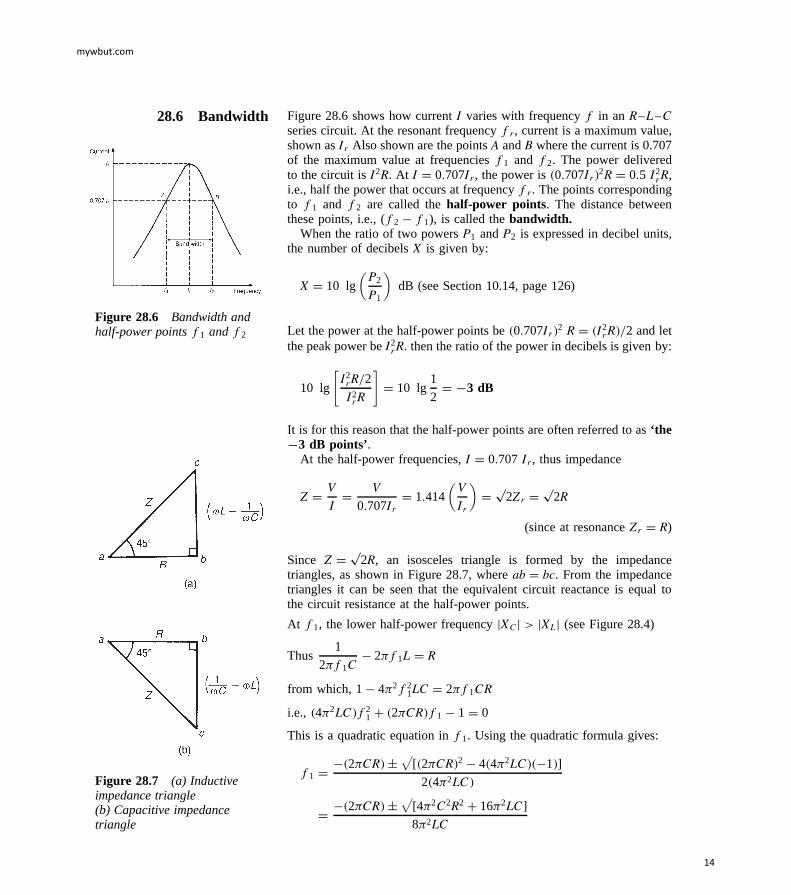
28.6 Bandwidth Figure 28.6 shows how current I varies with frequency f in an R–L–Cseries circuit. At the resonant frequency fr , current is a maximum value,shown as Ir Also shown are the points A and B where the current is 0.707of the maximum value at frequencies f1 and f2. The power deliveredto the circuit is I2R. At I D 0.707Ir , the power is 0.707Ir2R D 0.5 I2
rR,i.e., half the power that occurs at frequency fr . The points correspondingto f1 and f2 are called the half-power points. The distance betweenthese points, i.e., (f2 f1), is called the bandwidth.
When the ratio of two powers P1 and P2 is expressed in decibel units,the number of decibels X is given by:
X D 10 lg(P2
P1
)dB (see Section 10.14, page 126)
Figure 28.6 Bandwidth andhalf-power pointsf1 andf2 Let the power at the half-power points be 0.707Ir2 R D I2
r R/2 and letthe peak power be I2
rR. then the ratio of the power in decibels is given by:
10 lg
[I2rR/2
I2rR
]D 10 lg
1
2D −3 dB
It is for this reason that the half-power points are often referred to as ‘the−3 dB points’.
At the half-power frequencies, I D 0.707 Ir , thus impedance
Z D V
ID V
0.707IrD 1.414
(V
Ir
)D p
2Zr D p2R
(since at resonance Zr D R)
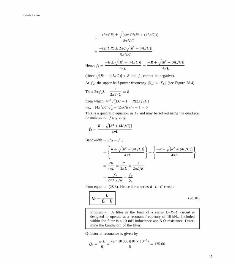
Since Z D p2R, an isosceles triangle is formed by the impedance
triangles, as shown in Figure 28.7, where ab D bc. From the impedancetriangles it can be seen that the equivalent circuit reactance is equal tothe circuit resistance at the half-power points.
At f1, the lower half-power frequency jXCj > jXLj (see Figure 28.4)
Thus1
2f1C 2f1L D R
from which, 1 42f21LC D 2f1CR
i.e., 42LCf21 C 2CRf1 1 D 0
This is a quadratic equation in f1. Using the quadratic formula gives:
At f2, the upper half-power frequency jXLj > jXCj (see Figure 28.4)
Thus 2f2L 1
2f2CD R
from which, 42f22LC 1 D R2f2C
i.e., 42LCf22 2CRf2 1 D 0
This is a quadratic equation in f2 and may be solved using the quadraticformula as for f1, giving:
f2 =RY
√[R2 Y .4L=C/]
4pL
Bandwidth D f2 f1
DR C
√[R2 C 4L/C]
4L
R C√
[R2 C 4L/C]
4L
D 2R
4LD R
2LD 1
2L/R
D fr
2frL/RD fr
Qr
from equation (28.3). Hence for a series R–L–C circuit
Qr =fr
f2 − f128.10
Problem 7. A filter in the form of a series L–R–C circuit isdesigned to operate at a resonant frequency of 10 kHz. Includedwithin the filter is a 10 mH inductance and 5 resistance. Deter-mine the bandwidth of the filter.
Q-factor at resonance is given by
Qr D ωrL
RD 2 10 00010 ð 103
5D 125.66
mywbut.com
15
Since Qr D fr/f2 f1,
Bandwidth, . f2 − f1/ D fr
QrD 10 000
125.66D 79.6 Hz
An alternative equation involving fr
At the lower half-power frequency f1:1
ω1C ω1L D R
At the higher half-power frequency f2: ω2L 1
ω2CD R
Equating gives:1
ω1C ω1L D ω2L 1
ω2C
Multiplying throughout by C gives:1
ω1 ω1LC D ω2LC 1
ω2
However, for series resonance, ω2r D 1/LC
Hence1
ω1 ω1
ω2r
D ω2
ω2r
1
ω2
i.e.,1
ω1C 1
ω2D ω2
ω2r
C ω1
ω2r
D ω1 C ω2
ω2r
Thereforeω2 C ω1
ω1ω2D ω1 C ω2
ω2r
,
from which, ω2r D ω1ω2 or ωr D p
ω1ω2
Hence 2fr D p[2f12f2] and fr =
p.f1 f2/ 28.11
Selectivity is the ability of a circuit to respond more readily to signals ofa particular frequency to which it is tuned than to signals of other frequen-cies. The response becomes progressively weaker as the frequency departsfrom the resonant frequency. Discrimination against other signals becomesmore pronounced as circuit losses are reduced, i.e., as the Q-factor isincreased. Thus Qr D fr/f2 f1 is a measure of the circuit selec-tivity in terms of the points on each side of resonance where the circuitcurrent has fallen to 0.707 of its maximum value reached at resonance.The higher the Q-factor, the narrower the bandwidth and the more selec-tive is the circuit. Circuits having high Q-factors (say, in the order 300)are therefore useful in communications engineering. A high Q-factor in aseries power circuit has disadvantages in that it can lead to dangerouslyhigh voltages across the insulation and may result in electrical breakdown.
For example, suppose that the working voltage of a capacitor is statedas 1 kV and is used in a circuit having a supply voltage of 240 V. Themaximum value of the supply will be
p2240, i.e., 340 V. The working
voltage of the capacitor would appear to be ample. However, if the Q-factor is, say, 10, the voltage across the capacitor will reach 2.4 kV.
mywbut.com
16
Since the capacitor is rated only at 1 kV, dielectric breakdown is morethan likely to occur.
Low Q-factors, say, in the order of 5 to 25, may be found in powertransformers using laminated iron cores.
A capacitor-start induction motor, as used in domestic appliances suchas washing machines and vacuum-cleaners, having a Q-factor as low as1.5 at starting would result in a voltage across the capacitor 1.5 times thatof the supply voltage; hence the cable joining the capacitor to the motorwould require extra insulation.
Problem 8. An R–L–C series circuit has a resonant frequencyof 1.2 kHz and a Q-factor at resonance of 30. If the impedanceof the circuit at resonance is 50 determine the values of (a) theinductance, and (b) the capacitance. Find also (c) the bandwidth,(d) the lower and upper half-power frequencies and (e) the valueof the circuit impedance at the half-power frequencies.
(a) At resonance the circuit impedance, Z D R, i.e., R D 50 .
Q-factor at resonance, Qr D ωrL/R
Hence inductance, L D QrR
ωrD 3050
21200D 0.199 H or 199 mH
(b) At resonance ωrL D 1/ωrC
Hence capacitance, C D 1
ω2r L
D 1
2120020.199
D 0.088 mF or 88 nF
(c) Q-factor at resonance is also given by Qr D fr/f2 f1, fromwhich,
bandwidth,.f2 − f1/ D fr
QrD 1200
30D 40 Hz
(d) From equation (28.11), resonant frequency, fr D pf1f2,
i.e., 1200 D pf1f2
from which, f1f2 D 12002 D 1.44 ð 106 28.12
From part(c), f2 f1 D 40 28.13
From equation (28.12), f1 D 1.44 ð 106/f2
Substituting in equation (28.13) gives:
f2 1.44 ð 106
f2D 40
mywbut.com
17
Multiplying throughout by f2 gives:
f22 1.44 ð 106 D 40f2
i.e., f22 40f2 1.44 ð 106 D 0
This is a quadratic equation in f2. Using the quadratic formula gives:
f2 D 40 š√
[402 41.44 ð 106]
2D 40 š 2400
2
D 40 C 2400
2(since f2 cannot be negative)
Hence the upper half-power frequency, f2 = 1220 HzFrom equation (28.12), the lower half-power frequency,
f1 D f2 40 D 1220 40 D 1180 Hz
Note that the upper and lower half-power frequency values aresymmetrically placed about the resonance frequency. This is usuallythe case when the Q-factor has a high value (say, >10).
(e) At the half-power frequencies, current I D 0.707 Ir
Hence impedance,
Z D V
ID V
0.707 IrD 1.414
(V
Ir
)D p
2Zr D p2R
Thus impedance at the half-power frequencies,Z D p
2R D p250 D 70.71 Z
Problem 9. A series R–L–C circuit is connected to a 0.2 V supplyand the current is at its maximum value of 4 mA when the supplyfrequency is adjusted to 3 kHz. The Q-factor of the circuit underthese conditions is 100. Determine the value of (a) the circuit resis-tance, (b) the circuit inductance, (c) the circuit capacitance, and(d) the voltage across the capacitor
Since the current is at its maximum, the circuit is at resonance and theresonant frequency is 3 kHz.
(a) At resonance, impedance, Z D R D V
ID 0.2
4 ð 103D 50
Hence the circuit resistance in 50 Z
(b) Q-factor at resonance is given by Qr D ωrL/R, from which,
inductance, L D QrR
ωrD 10050
23000D 0.265 H or 265 mH
mywbut.com
18
(c) Q-factor at resonance is also given by Qr D 1/ωrCR, from which,
capacitance, C D 1
ωrRQrD 1
2300050100
D 0.0106 mF or 10.6 nF
(d) Q-factor at resonance in a series circuit represents thevoltage magnification, i.e., Qr D VC/V, from which, VC D QrV D1000.2 D 20 V.
Hence the voltage across the capacitor is 20 V
Alternatively, VC D IXC D I
ωrCD 4 ð 103
230000.0106 ð 106
D 20 V
Problem 10. A coil of inductance 351.8 mH and resistance 8.84 is connected in series with a 20 µF capacitor. Determine (a) theresonant frequency, (b) the Q-factor at resonance, (c) the band-width, and (d) the lower and upper 3dB frequencies.
(a) Resonant frequency, fr D 1
2pLC
D 1
2√
[0.351820 ð 106]
D 60.0 Hz
(b) Q-factor at resonance, Qr D 1
R
√L
CD 1
8.84
√(0.3518
20 ð 106
)D 15
[Alternatively, Qr D ωrL
RD 260.00.3518
8.84D 15
or Qr D 1
ωrCRD 1
260.020 ð 1068.84D 15
]
(c) Bandwidth, .f2 − f1/ D fr
QrD 60.0
15D 4 Hz
(d) With a Q-factor of 15 it may be assumed that the lower and upper3 dB frequencies, f1 and f2 are symmetrically placed about theresonant frequency of 60.0 Hz. Hence the lower −3 dB frequency,f1 = 58 Hz, and the upper −3 dB frequency, f2 D 62 Hz.
[This may be checked by using f2 f1 D 4 and fr D pf1f2]
28.7 Small deviationsfrom the resonant
frequency
Let ω1 be a frequency below the resonant frequency ωr in an L–R–Cseries circuit, and ω2 be a frequency above ωr by the same amount as ω1
is below, i.e., ωr ω1 D ω2 ωr
mywbut.com
19
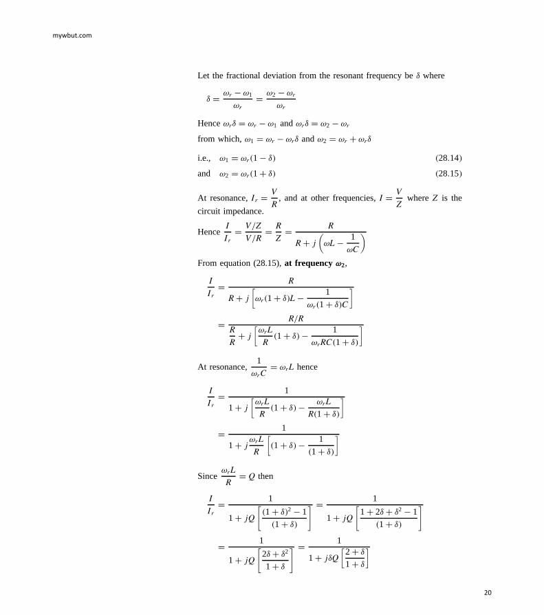
Let the fractional deviation from the resonant frequency be υ where
υ D ωr ω1
ωrD ω2 ωr
ωr
Hence ωrυ D ωr ω1 and ωrυ D ω2 ωr
from which, ω1 D ωr ωrυ and ω2 D ωr C ωrυ
i.e., ω1 D ωr1 υ 28.14
and ω2 D ωr1 C υ 28.15
At resonance, Ir D V
R, and at other frequencies, I D V
Zwhere Z is the
circuit impedance.
HenceI
IrD V/Z
V/RD R
ZD R
R C j(ωL 1
ωC
)
From equation (28.15), at frequency !2,
I
IrD R
R C j[ωr1 C υL 1
ωr1 C υC
]
D R/RR
RC j
[ωrL
R1 C υ 1
ωrRC1 C υ
]
At resonance,1
ωrCD ωrL hence
I
IrD 1
1 C j[ωrL
R1 C υ ωrL
R1 C υ
]
D 1
1 C jωrL
R
[1 C υ 1
1 C υ
]
SinceωrL
RD Q then
I
IrD 1
1 C jQ
[1 C υ2 1
1 C υ
] D 1
1 C jQ
[1 C 2υ C υ2 1
1 C υ
]
D 1
1 C jQ
[2υ C υ2
1 C υ
] D 1
1 C jυQ[
2 C υ
1 C υ
]
mywbut.com
20
If the deviation from the resonant frequency υ is very small such thatυ − 1
thenI
Ir³ 1
1 C jυQ[
21
] D 11Y j 2dQ
28.16
andI
IrD V/Z
V/ZrD Zr
ZD 1
1 C j2dQ
from which,ZZr
= 1Y j 2dQ 28.17
It may be shown that at frequency !1,I
IrD 1
1 − j 2dQand
ZZr
= 1 − j 2dQ
Problem 11. In an L–R–C series network, the inductance, L D8 mH, the capacitance, C D 0.3 µF, and the resistance, R D 15 .Determine the current flowing in the circuit when the input voltageis 7.5 6 0° V and the frequency is (a) the resonant frequency, (b) afrequency 3% above the resonant frequency. Find also (c) theimpedance of the circuit when the frequency is 3% above theresonant frequency.
(a) At resonance, Zr D R D 15
Current at resonance, I r D V
ZrD 7.5 6 0°
15 6 0°D 0.5 6 0° A
(b) If the frequency is 3% above the resonant frequency, then υ D 0.03
From equation (28.16),I
IrD 1
1 C j2υQ
Q D 1
R
√L
CD 1
15
√(8 ð 103
0.3 ð 106
)D 10.89
HenceI
0.5 6 0°D 1
1 C j20.0310.89D 1
1 C j0.6534
D 1
1.1945 6 33.16°
and I D 0.5 6 0°
1.1945 6 33.16°D 0.4186 6 −33.16° A
(c) From equation (28.17),Z
ZrD 1 C j2υQ
mywbut.com
21
hence Z D Zr1 C j2υQ D R1 C j2υQ
D 151 C j20.0310.89
D 151 C j0.6534
D 151.1945 6 33.16°
D 17.92 6 33.16° Z
Alternatively, Z D V
ID 7.5 6 0°
0.4186 6 33.16°D 17.92 6 33.16°
Furtherproblems on Q-factor and bandwidth may be found in Section 28.8following, problems 6 to 16, page 513
28.8 Further problemson series resonance and
Q-factor
Series resonance
1 A coil having an inductance of 50 mH and resistance 8.0 isconnected in series with a 25 µF capacitor across a 100 V a.c.supply. Determine (a) the resonant frequency of the circuit, and(b) the current flowing at resonance. [(a) 142.4 Hz (b) 12.5 A]
2 The current at resonance in a series R–L–C circuit is 0.12 mA. Thecircuit has an inductance of 0.05 H and the supply voltage is 24 mVat a frequency of 40 kHz. Determine (a) the circuit resistance, and(b) the circuit capacitance. [(a) 200 (b) 316.6 pF]
3 A coil of inductance 2.0 mH and resistance 4.0 is connected inseries with a 0.3 µF capacitor. The circuit is connected to a 5.0 V,variable frequency supply. Calculate (a) the frequency at which reso-nance occurs, (b) the voltage across the capacitance at resonance, and(c) the voltage across the coil at resonance.
[(a) 6.50 kHz (b) 102.1 V (c) 102.2 V]
4 A series R–L–C circuit having an inductance of 0.40 H hasan instantaneous voltage, v D 60 sin4000t /6 volts and aninstantaneous current, i D 2.0 sin 4000t amperes. Determine (a) thevalues of the circuit resistance and capacitance, and (b) the frequencyat which the circuit will be resonant.
[(a) 26 ; 154.8 nF (b) 639.6 Hz]
5 A variable capacitor C is connected in series with a coil havinginductance L. The circuit possesses stray capacitance CS which isassumed to be constant and effectively in parallel with the variablecapacitor C. When the capacitor is set to 2.0 nF the resonantfrequency of the circuit is 86.85 kHz, and when the capacitor is setto 1.0 nF the resonant frequency is 120 kHz. Determine the valuesof (a) the stray circuit capacitance CS, and (b) the coil inductance L.
[(a) 100 pF (b) 1.60 mH]
mywbut.com
22
Q-factor and bandwidth
6 A series R–L–C circuit comprises a 5 µF capacitor, a 4 resistorand a variable inductance L. The supply voltage is 10 6 0° V at afrequency of 159.1 Hz. The inductance is adjusted until the p.d.across the 4 resistance is a maximum. Determine for this condition(a) the value of inductance, (b) the p.d. across each component, and(c) the Q-factor of the circuit.
[(a) 200 mH (b) VR D 10 6 0° VIVL D 500 6 90° VIVC D 500 6 90° V (c) 50]
7 A coil of resistance 10.05 and inductance 400 mH is connectedin series with a 0.396 µF capacitor. Determine (a) the resonantfrequency, (b) the resonant Q-factor, (c) the bandwidth, and (d) thelower and upper half-power frequencies.
8 An R–L–C series circuit has a resonant frequency of 2 kHz anda Q-factor at resonance of 40. If the impedance of the circuitat resonance is 30 determine the values of (a) the inductanceand (b) the capacitance. Find also (c) the bandwidth, (d) the lowerand upper 3 dB frequencies, and (e) the impedance at the 3 dBfrequencies.
9 A filter in the form of a series L–C–R circuit is designed to operateat a resonant frequency of 20 kHz and incorporates a 20 mH inductorand 30 resistance. Determine the bandwidth of the filter.
[238.7 Hz]
10 A series L–R–C circuit has a supply input of 5 volts. Given thatinductance, L D 5 mH, resistance, R D 75 and capacitance, C D0.2 µF, determine (a) the resonant frequency, (b) the value of voltageacross the capacitor at the resonant frequency, (c) the frequency atwhich the p.d. across the capacitance is a maximum, and (d) thevalue of the maximum voltage across the capacitor.
[(a) 5033 Hz (b) 10.54 V (c) 4741 Hz (d) 10.85 V]
11 A capacitor having a Q-factor of 250 is connected in series with acoil which has a Q-factor of 80. Calculate the overall Q-factor of thecircuit. [60.61]
12 An R–L–C series circuit has a maximum current of 2 mA flowingin it when the frequency of the 0.1 V supply is 4 kHz. The Q-factorof the circuit under these conditions is 90. Determine (a) the voltageacross the capacitor, and (b) the values of the circuit resistance,inductance and capacitance. [(a) 9 V (b) 50 ; 0.179 H; 8.84 nF]
13 Calculate the inductance of a coil which must be connected inseries with a 4000 pF capacitor to give a resonant frequency of200 kHz. If the coil has a resistance of 12 , determine the circuitQ-factor. [158.3 µH; 16.58]
mywbut.com
23
14 A circuit consists of a coil of inductance 200 µH and resistance 8.0 in series with a lossless 500 pF capacitor. Determine (a) the resonantQ-factor, and (b) the bandwidth of the circuit.
[(a) 79.06 (b) 6366 Hz]
15 A coil of inductance 200 µH and resistance 50.27 and a variablecapacitor are connected in series to a 5 mV supply of frequency2 MHz. Determine (a) the value of capacitance to tune the circuitto resonance, (b) the supply current at resonance, (c) the p.d. acrossthe capacitor at resonance, (d) the bandwidth, and (e) the half-powerfrequencies.
16 A supply voltage of 3 V is applied to a series R–L–C circuitwhose resistance is 12 , inductance is 7.5 mH and capacitanceis 0.5 µF. Determine (a) the current flowing at resonance, (b) thecurrent flowing at a frequency 2.5% below the resonant frequency,and (c) the impedance of the circuit when the frequency is 1% lowerthan the resonant frequency.
ž state the condition for resonance in an a.c. parallel networkž calculate the resonant frequency in a.c. parallel networks
ž calculate dynamic resistanceRD D L
CRin an a.c. parallel
network
ž calculate Q-factor and bandwidth in an a.c. parallel networkž determine the overall Q-factor for capacitors connected in
parallelž determine the impedance when the frequency deviates from
the resonant frequency
29.1 Introduction A parallel network containing resistanceR, pure inductanceL and purecapacitanceC connected in parallel is shown in Figure 29.1. Since theinductance and capacitance are considered as pure components, this circuitis something of an ‘ideal’ circuit. However, it may be used to highlightsome important points regarding resonance which are applicable to anyparallel circuit.
From Figure 29.1,
the admittance of the resistive branch,G D 1
R
the admittance of the inductive branch,BL D 1
jXLD j
ωL
the admittance of the capacitive branch,BC D 1
jXC
D j
1/ωCD jωC
Figure 29.1 Parallel R–L–Ccircuit
Total circuit admittance,Y D G C jBC BL ,
i.e., Y D 1
RC j
(ωC 1
ωL
)
The circuit is at resonance when the imaginary part is zero, i.e., whenωC 1/ωL D 0. Hence at resonanceωrC D 1/ωrL andω2
r D 1/LC ,
mywbut.com
25
Figure 29.2 jYj plottedagainst frequency
from which ωr D 1/p
LC and the resonant frequency
fr =1
2pp
.LC /hertz
the same expression as for a seriesR–L–C circuit.Figure 29.2 shows typical graphs ofBC, BL, G and Y against
frequencyf for the circuit shown in Figure 29.1. At resonance,BC D BL
andadmittanceY D G D 1/R. This represents the condition ofminimumadmittance for the circuit and thusmaximum impedance.
Since currentI D V/Z D VY, the current is at aminimum value atresonance in a parallel network.
From the ideal circuit of Figure 29.1 we have therefore established thefollowing facts which apply to any parallel circuit. At resonance:
(i) admittanceY is a minimum(ii) impedanceZ is a maximum
(iii) current I is a minimum(iv) an expression for the resonant frequencyfr may be obtained
by making the ‘imaginary’ part of the complex expression foradmittance equal to zero.
29.2 The LR –C parallelnetwork
A more practical network, containing a coil of inductanceL and resistanceR in parallel with a pure capacitanceC, is shown in Figure 29.3.
Admittance of coil,YCOIL D 1
R C jXLD R jXL
R2 C X2L
D R
R2 C ω2L2 jωL
R2 C ω2L2
Figure 29.3
Admittance of capacitor,YC D 1
jXCD j
XcD jωC
Total circuit admittance,Y D YCOIL C YC
D R
R2 C ω2L2 jωL
R2 C ω2L2C jωC 29.1
At resonance, the total circuit admittanceY is realY D R/R2 C ω2L2 ,i.e., the imaginary part is zero. Hence, at resonance:
ωrL
R2 C ω2r L2
C ωrC D 0
mywbut.com
26
ThereforeωrL
R2 C ω2r L2
D ωrC andL
CD R2 C ω2
r L2
Thus ω2r L2 D L
C R2
and ω2r D L
CL2 R2
L2D 1
LC R2
L229.2
Hence ωr D√(
1
LC R2
L2
)
and resonant frequency, fr =1
2p
√(1
LC R2
L2
)29.3
Note that whenR2/L2 − 1/LC then fr D 1/2p
LC , as for theseries R–L–C circuit. Equation (29.3) is the same as obtained inChapter 16, page 248; however, the above method may be applied toany parallel network as demonstrated in Section 29.4 below.
29.3 Dynamic resistance Sincethe current at resonance is in phase with the voltage, the impedanceof the network acts as a resistance. This resistance is known as thedynamic resistance, RD . Impedance at resonance,RD D V/Ir, whereIr
is the current at resonance.
Ir D VYr D V(
R
R2 C ω2r L2
)
from equation (29.1) with the j terms equal to zero.
HenceRD D V
IrD V
VR/R2 C ω2r L2
D R2 C ω2r L2
R
D R2 C L21/LC R2/L2
Rfrom equation29.2
D R2 C L/C R2
RD L/C
RD L
CR
Hence dynamic resistance,RD =L
CR29.4
29.4 The LR –CRparallel network
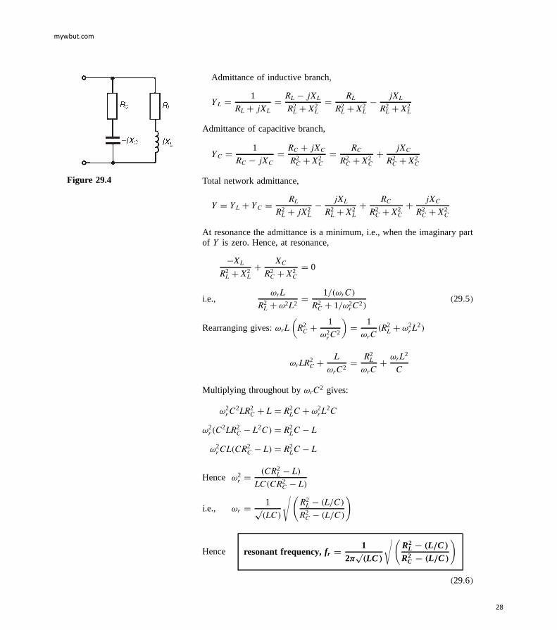
A more general network comprising a coil of inductanceL and resistanceRL in parallel with a capacitanceC and resistanceRC in series is shownin Figure 29.4.
mywbut.com
27
Figure 29.4
Admittance of inductive branch,
YL D 1
RL C jXLD RL jXL
R2L C X2
L
D RL
R2L C X2
L
jXL
R2L C X2
L
Admittanceof capacitive branch,
YC D 1
RC jXCD RC C jXC
R2C C X2
C
D RC
R2C C X2
C
C jXC
R2C C X2
C
Total network admittance,
Y D YL C YC D RL
R2L C jX2
L
jXL
R2L C X2
L
C RC
R2C C X2
C
C jXC
R2C C X2
C
At resonance the admittance is a minimum, i.e., when the imaginary partof Y is zero. Hence, at resonance,
XL
R2L C X2
L
C XC
R2C C X2
C
D 0
i.e.,ωrL
R2L C ω2L2
D 1/ωrC
R2C C 1/ω2
r C2 29.5
Rearranginggives:ωrL(
R2C C 1
ω2r C2
)D 1
ωrCR2
L C ω2r L2
ωrLR2C C L
ωrC2D R2
L
ωrCC ωrL2
C
Multiplying throughout byωrC2 gives:
ω2r C2LR2
C C L D R2LC C ω2
r L2C
ω2r C2LR2
C L2C D R2LC L
ω2r CLCR2
C L D R2LC L
Hence ω2r D CR2
L L
LCCR2C L
i.e., ωr D 1pLC
√(R2
L L/C
R2C L/C
)
Hence resonant frequency,fr =1
2pp
.LC /
√(R2
L − .L=C/
R2C − .L=C/
)
29.6
mywbut.com
28
It is clear from equation (29.5) that parallel resonance may be achievedin such a circuit in several ways — by varying either the frequencyf,the inductanceL, the capacitanceC, the resistanceRL or the resis-tanceRC.
29.5 Q-factor in aparallel network
The Q-factor in the seriesR–L–C circuit is a measure of the voltagemagnification. In a parallel circuit, currents higher than the supply currentcan circulate within the parallel branches of a parallel resonant network,the current leaving the capacitor and establishing the magnetic field ofthe inductance, this then collapsing and recharging the capacitor, andso on. The Q-factor of a parallel resonant circuit is the ratio of thecurrent circulating in the parallel branches of the circuit to the supplycurrent, i.e. in a parallel circuit, Q-factor is a measure of thecurrentmagnification.
Circulating currents may be several hundreds of times greater than thesupply current at resonance. For the parallel network of Figure 29.5, theQ-factor at resonance is given by:
Qr =circulating current
curr ent at resonance=
capacitor currentcurr ent at resonance
=IC
I r
Currentin capacitor,IC D V/XC D VωrCFigure 29.5
Current at resonance,Ir D V
RDD V
L/CRD VCR
L
HenceQr D IC
IrD VωrC
VCR/Li.e., Qr =
!r LR
the same expression as for series resonance.The difference between the resonant frequency of a series circuit and
that of a parallel circuit can be quite small. The resonant frequency ofa coil in parallel with a capacitor is shown in Equation (29.3); however,around the closed loop comprising the coil and capacitor the energy wouldnaturally resonate at a frequency given by that for a seriesR–L–C circuit,as shown in Chapter 28. This latter frequency is termed thenaturalfrequency, fn , and the frequency of resonance seen at the terminals ofFigure 29.5 is often called theforced resonant frequency, fr . (For aseries circuit, the forced and natural frequencies coincide.)
From the coil-capacitor loop of Figure 29.5,fn D 1
2p
LC
and the forced resonant frequency,fr D 1
2
√(1
LC R2
L2
)
mywbut.com
29
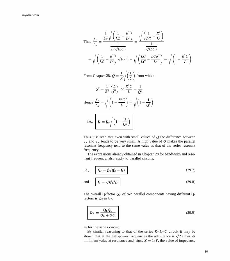
Thusfr
fnD
1
2
√(1
LC R2
L2
)
1
2p
LC
D
√(1
LC R2
L2
)
1pLC
D√(
1
LC R2
L2
)pLC D
√(LC
LC LCR2
L2
)D√(
1 R2C
L
)
From Chapter 28,Q D 1
R
√(L
C
)from which
Q2 D 1
R2
(L
C
)or
R2C
LD 1
Q2
Hencefr
fnD√(
1 R2C
L
)D√(
1 1
Q2
)
i.e., fr = fn
√(1 − 1
Q2
)
Thus it is seen that even with small values ofQ the difference betweenfr andfn tendsto be very small. A high value ofQ makes the parallelresonant frequency tend to the same value as that of the series resonantfrequency.
The expressions already obtained in Chapter 28 for bandwidth and reso-nant frequency, also apply to parallel circuits,
i.e., Qr = fr =.f2 − f1/ 29.7
and fr =p
.f1 f2/ 29.8
The overall Q-factorQT of two parallel components having different Q-factors is given by:
QT =QLQC
QL YQC29.9
asfor the series circuit.By similar reasoning to that of the seriesR–L–C circuit it may be
shown that at the half-power frequencies the admittance isp
2 times itsminimum value at resonance and, sinceZ D 1/Y, the value of impedance
mywbut.com
30
at the half-power frequencies is 1/p
2 or 0.707 times its maximum valueat resonance.
By similar analysis to that given in Chapter 28, it may be shown thatfor a parallel network:
YYr
=RD
Z= 1Y j 2dQ 29.10
where Y is the circuit admittance,Yr is the admittance at resonance,Z is the network impedance andRD is the dynamic resistance (i.e., theimpedance at resonance) andυ is the fractional deviation from the resonantfrequency.
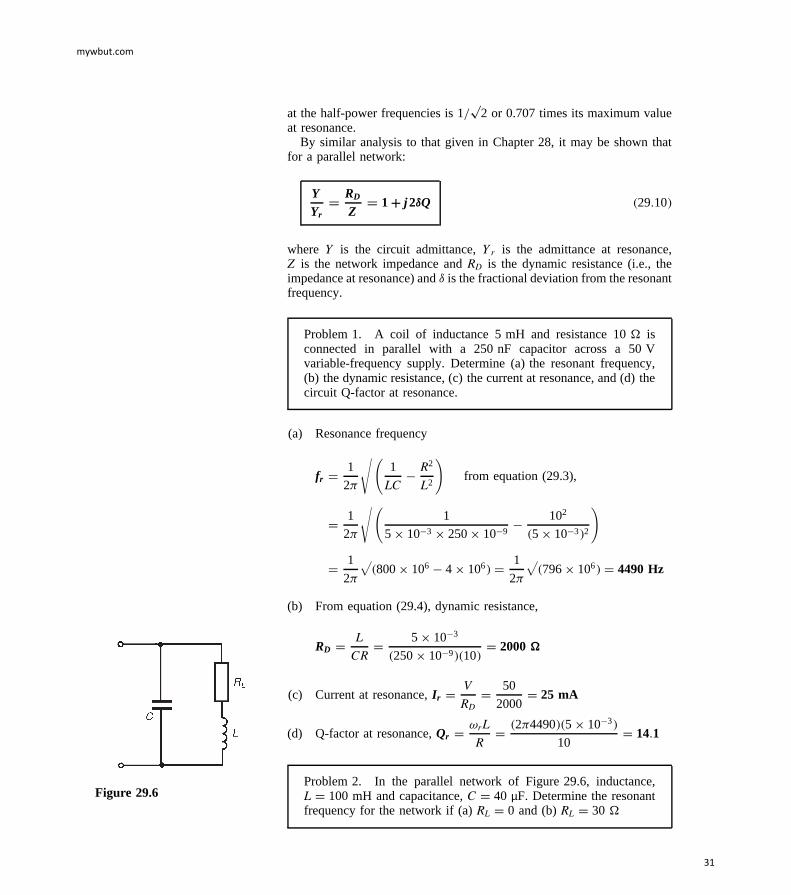
Problem1. A coil of inductance 5 mH and resistance 10 isconnected in parallel with a 250 nF capacitor across a 50 Vvariable-frequency supply. Determine (a) the resonant frequency,(b) the dynamic resistance, (c) the current at resonance, and (d) thecircuit Q-factor at resonance.
(a) Resonance frequency
fr D 1
2
√(1
LC R2
L2
)from equation (29.3),
D 1
2
√(1
5 ð 103 ð 250ð 109 102
5 ð 103 2
)
D 1
2
√800ð 106 4 ð 106 D 1
2
√796ð 106 D 4490Hz
(b) From equation (29.4), dynamic resistance,
RD D L
CRD 5 ð 103
250ð 109 10 D 2000Z
(c) Current at resonance,I r D V
RDD 50
2000D 25 mA
(d) Q-factor at resonance,Qr D ωrL
RD 24490 5 ð 103
10D 14.1
Problem2. In the parallel network of Figure 29.6, inductance,L D 100 mH and capacitance,C D 40 µF. Determine the resonantfrequency for the network if (a)RL D 0 and (b)RL D 30
Figure 29.6
mywbut.com
31
Total circuit admittance,
Y D 1
RL C jXLC 1
jXCD RL jXL
R2L C X2
L
C j
XC
D RL
R2L C X2
L
jXL
R2L C X2
L
C j
XC
Thenetwork is at resonance when the admittance is at a minimum value,i.e., when the imaginary part is zero. Hence, at resonance,
XL
R2L C X2
L
C 1
XCD 0 or ωrC D ωrL
R2L C ω2
r L229.11
(a) WhenRL D 0, ωrC D ωrL
ω2r L2
from which, ω2r D 1
LCandωr D 1p
LC
Hence resonant frequency,
fr D 1
2p
LC D 1
2√
100ð 103 ð 40ð 106 D 79.6 Hz
(b) WhenRL D 30, ωrC D ωrL
302 C ω2r L2
from equation (29.11) above
from which, 302 C ω2r L2 D L
C
i.e., ω2r 100ð 103 2 D 100ð 103
40ð 106 900
i.e., ω2r 0.01 D 2500 900D 1600
Thus,ω2r D 1600/0.01 D 160000 andωr D p
160000D 400 rad/s
Hence resonant frequency,fr D 400
2D 63.7 Hz
[Alternatively, from equation (29.3),
fr D 1
2
√(1
LC R2
L2
)
D 1
2
√(1
100ð 103 40ð 106 302
100ð 103 2
)
D 1
2
p25000090 000 D 1
2
p160000D 1
2400 D63.7 Hz]
mywbut.com
32
Hence, as the resistance of a coil increases, the resonant frequencydecreases in the circuit of Figure 29.6.
Problem3. A coil of inductance 120 mH and resistance 150is connected in parallel with a variable capacitor across a 20 V,4 kHz supply. Determine for the condition when the supply currentis a minimum, (a) the capacitance of the capacitor, (b) the dynamicresistance, (c) the supply current, (d) the Q-factor, (e) the band-width, (f) the upper and lower3 dB frequencies, and (g) the valueof the circuit impedance at the3 dB frequencies.
(a) The supply current is a minimum when the parallel network is atresonance.
Resonant frequency,fr D 1
2
√(1
LC R2
L2
)from equation (29.3),
from which, 2fr 2 D 1
LC R2
L2
Hence1
LCD 2fr
2 C R2
L2and
capacitanceC D 1
L[2fr 2 C R2/L2 ]
D 1
120ð 103[24000 2 C 1502/120ð 103 2 ]
D 1
0.12631.65ð 106 C 1.5625ð 106
D 0.01316mF or 13.16 nF
(b) Dynamic resistance,RD D L
CRD 120ð 103
13.16ð 109 150
D 60.79 kZ
(c) Supply current at resonance,
I r D V
RDD 20
60.79ð 103D 0.329 mA or 329mA
(d) Q-factor at resonance,Qr D ωrL
RD 24000 120ð 103
150D 20.11
[Note that the expressionsQr D 1
ωrCRor Qr D 1
R
√(L
C
)
mywbut.com
33
used for the R–L–C series circuit may also be used in parallelcircuits when the resistance of the coil is much smaller than theinductive reactance of the coil.
In this caseR D 150 andXL D 24000 120ð 103 D 3016.
Hence,alternatively,
Qr D 1
ωrCRD 1
24000 13.16ð 109 150 D 20.16
or Qr D 1
R
√(L
C
)D 1
150
√(120ð 103
13.16ð 109
)D 20.13]
(e) If the lower and upper3 dB frequencies aref1 andf2 respectivelythen the bandwidth isf2 f1 . Q-factor at resonance is given byQr D fr/f2 f1 , from which, bandwidth,
.f2 − f1/ D fr
QrD 4000
20.11D 199 Hz
(f) Resonant frequency,fr D pf1f2 , from which
f1f2 D f2r D 4000 2 D 16ð 106 29.12
Also, from part (e),f2 f1 D 199 29.13
From equation (29.12), f1 D 16ð 106
f2
Substitutingin equation (29.13) gives:f2 16ð 106
f2D 199
i.e., f22 16ð 106 D 199f2 from which,
f22 199f2 16ð 106 D 0.
Solving this quadratic equation gives:
f2 D 199š√
[199 2 416ð 106 ]
2D 199š 8002.5
2
i.e., the upper 3 dB frequency,f2 = 4100Hz (neglecting the nega-tive answer).
From equation (29.12),
the lower −3 dB frequency, f1 D 10ð 106
f2D 16ð 106
4100
D 3900Hz
mywbut.com
34
(Note that f1 and f2 are equally displaced about the resonantfrequency,fr , as they always will be whenQ is greater than about10 — just as for a series circuit)
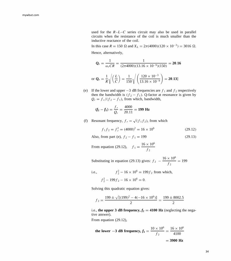
(g) The value of the circuit impedance,Z, at the3 dB frequencies isgiven by
Z D 1p2
Zr
whereZr is the impedance at resonance.
The impedance at resonanceZr D RD, the dynamic resistance.
Henceimpedance at the−3 dB frequenciesD 1p2
60.79ð 103
D 42.99 kZ
Figure 29.7 shows impedance plotted against frequency for thecircuit in the region of the resonant frequency.
= = Ω
Ω
−
√
Figure 29.7
Problem4. A two-branch parallel network is shown inFigure 29.8. Determine the resonant frequency of the network.
Figure 29.8
From equation (29.6),
resonant frequency,fr D 1
2p
LC
√(R2
L L/C
R2C L/C
)
whereRL D 5 , RC D 3 , L D 2 mH and CD 25 µF. Thus
fr D 1
2√
[2 ð 103 25ð 106 ]
√(522 ð 103 /25ð 106
322 ð 103 /25ð 106
)
D 1
2√
5 ð 108
√(25 80
9 80
)
D 104
2p
5
√(55
71
)D 626.5 Hz
Problem5. Determine for the parallel network shown inFigure 29.9 the values of inductanceL for which the network isresonant at a frequency of 1 kHz.
Figure 29.9
mywbut.com
35
The total network admittance,Y, is given by
Y D 1
3 C jXLC 1
4 j10D 3 jXL
32 C X2L
C 4 C j10
42 C 102
D 3
32 C X2L
jXL
32 C X2L
C 4
116C j10
116
D(
3
32 C X2L
C 4
116
)C j
(10
116 XL
32 C X2L
)
Resonanceoccurs when the admittance is a minimum, i.e., when theimaginary part ofY is zero. Hence, at resonance,
10
116 XL
32 C X2L
D 0 i.e.,10
116D XL
32 C X2L
Therefore109 C X2L D 116 XL i.e., 10 X2
L 116 XL C 90 D 0
from which, X2L 11.6 XL C 9 D 0
Solving the quadratic equation gives:
XL D 11.6 š√
[11.6 2 49 ]
2D 11.6 š 9.93
2
i.e., XL D 10.765 or 0.835. Hence 10.765D 2frL1, from which,
inductanceL1 D 10.765
21000 D 1.71 mH
and 0.835D 2frL2 from which,
inductance,L2 D 0.835
21000 D 0.13 mH
Thus the conditions for the circuit of Figure 29.9 to be resonant arethat inductance L is either 1.71 mH or 0.13 mH
Problem6. A capacitor having a Q-factor of 300 is connected inparallel with a coil having a Q-factor of 60. Determine the overallQ-factor of the parallel combination.
From equation (29.9), the overall Q-factor is given by:
QT D QLQC
QL C QCD 60 300
60C 300D 18000
360D 50
mywbut.com
36
Problem7. In anLR–C network, the capacitance is 10.61 nF, thebandwidth is 500 Hz and the resonant frequency is 150 kHz. Deter-mine for the circuit (a) the Q-factor, (b) the dynamic resistance, and(c) the magnitude of the impedance when the supply frequency is0.4% greater than the tuned frequency.
(a) From equation (29.7),Q D fr
f2 f1D 150ð 103
500D 300
(b) From equation (29.4), dynamic resistance,RD D L
CR
Also, in an LR–C network,Q D ωrL
Rfrom which, R D ωrL
Q
Hence,RD D L
CRD L
C(
ωrL
Q
) D LQ
CωrLD Q
ωrC
D 300
2150ð 103 10.61ð 109 D 30 kZ
(c) From equation (29.10),RD
ZD 1 C j2υQ from which,Z D RD
1 C j2υQ
υ D 0.4% D 0.004 henceZ D 30ð 103
1 C j20.004 300
D 30ð 103
1 C j2.4D 30ð 103
2.66 67.38°
D 11.546 67.38° k
Hence the magnitude of the impedancewhen the frequency is 0.4%greater than the tuned frequency is11.54 kZ.
Further problems on parallel resonance may be found in the Section 29.6following, problems 1 to 14.
29.6 Further problemson parallel resonance and
Q-factor
1 A coil of resistance 20 and inductance 100 mH is connected inparallel with a 50µF capacitor across a 30 V variable-frequencysupply. Determine (a) the resonant frequency of the circuit, (b) thedynamic resistance, (c) the current at resonance, and (d) the circuitQ-factor at resonance. [(a) 63.66 Hz (b) 100 (c) 0.30 A (d) 2]
2 A 25 V, 2.5 kHz supply is connected to a network comprising avariable capacitor in parallel with a coil of resistance 250 andinductance 80 mH. Determine for the condition when the supply
mywbut.com
37
Figure 29.10
current is a minimum (a) the capacitance of the capacitor, (b) thedynamic resistance, (c) the supply current, (d) the Q-factor, (e) thebandwidth, (f) the upper and lower half-power frequencies and(g) the value of the circuit impedance at the3 dB frequencies.
3 A 0.1 µF capacitor and a pure inductance of 0.02 H are connected inparallel across a 12 V variable-frequency supply. Determine (a) theresonant frequency of the circuit, and (b) the current circulating inthe capacitance and inductance at resonance.
[(a) 3.56 kHz (b) 26.84 mA]
4 A coil of resistance 300 and inductance 100 mH and a 4000 pFcapacitor are connected (i) in series and (ii) in parallel. Find for eachconnection (a) the resonant frequency, (b) the Q-factor, and (c) theimpedance at resonance.
5 A network comprises a coil of resistance 100 and inductance 0.8 Hand a capacitor having capacitance 30µF. Determine the resonantfrequency of the network when the capacitor is connected (a) inseries with, and (b) in parallel with the coil.
[(a) 32.5 Hz (b) 25.7 Hz]Figure 29.116 Determine the value of capacitorC shown in Figure 29.10 for which
the resonant frequency of the network is 1 kHz. [2.30µF]
7 In the parallel network shown in Figure 29.11, inductanceL is40 mH and capacitanceC is 5 µF. Determine the resonant frequencyof the circuit if (a)RL D 0 and (b)RL D 40 .
[(a) 355.9 Hz (b) 318.3 Hz]
8 A capacitor of reactance 5 is connected in series with a 10resistor. The whole circuit is then connected in parallel with a coilof inductive reactance 20 and a variable resistor. Determine thevalue of this resistance for which the parallel network is resonant.
[10 ]Figure 29.129 Determine, for the parallel network shown in Figure 29.12, the values
of inductanceL for which the circuit is resonant at a frequency of600 Hz. [2.50 mH or 0.45 mH]
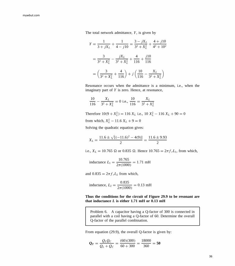
10 Find the resonant frequency of the two-branch parallel networkshown in Figure 29.13. [667 Hz]
11 Determine the value of the variable resistanceR in Figure 29.14 forwhich the parallel network is resonant. [11.87 ]
12 For the parallel network shown in Figure 29.15, determine theresonant frequency. Find also the value of resistance to be connectedin series with the 10µF capacitor to change the resonant frequencyto 1 kHz. [928 Hz; 5.27]
mywbut.com
38
Figure 29.13 Figure 29.14 Figure 29.15
13 Determine the overall Q-factor of a parallel arrangement consistingof a capacitor having a Q-factor of 410 and an inductor having aQ-factor of 90. [73.8]
14 The value of capacitance in anLR–C parallel network is 49.74 nF. Ifthe resonant frequency of the circuit is 200 kHz and the bandwidth is800 Hz, determine for the network (a) the Q-factor, (b) the dynamicresistance, and (c) the magnitude of the impedance when the supplyfrequency is 0.5% smaller than the tuned frequency.


![Report (1) Series Resonance - Cairo University 2020. 8. 13. · Question[6]: A series resonance circuit has a resonance frequency of 10 KHz . The resistance of the circuit is 5 Ω](https://static.documents.pub/doc/80x56/5fde2f557df0fb6049682608/report-1-series-resonance-cairo-university-2020-8-13-question6-a-series.jpg)
