245 www.ijifr.com Published Online On: 30/09/2015 International Journal of Informative & Futuristic Research ISSN: 2347-1697 Volume 3 Issue 1 September 2015 Abstract Tubular turbine is widely used in a hydro power station with the head of 2- 30meters. The blades are fixed or can adjust manually the efficient turbine of this kind can produce a large quantity of water flow which passes unimpededly.In this thesis, three-dimensional coupled design model for runner blades and guide vanes of bulb tubular turbine is designed and modeled in 3D modeling software Pro/Engineer. Finite element analysis is performed to simulate behaviors of guide vane wake flow that has significant influence on the inflow of runner blades. The CFD analysis and structural analysis is done to analyze the pressure distribution and the runner’s efficiency. Analysis is performed in Ansys. The original Tubular turbine has runner with arced blade shape. In this thesis, the shape of the blade is modified to straight and the comparison is made between arced and straight blade of the runner. The runner is designed in Pro/Engineer 3D modeling software. Fluid – Solid interaction is performed to simulate behavior of fluid flow on runner blade with different volume flow inlets (i.e., 100, 200, 300 & 400m3/s) and thereby determining stresses due to pressure developed from fluid flow. Stainless Steel is used as the runner blade material for static analysis and fluid is water. Design And Finite Element Analysis Of Three- Dimensional Coupled Design For Runner Blades And Guide Vanes Of Tubular Turbine Paper ID IJIFR/ V3/ E1/ 044 Page No. 245-257 Subject Area Mechanical Engineering Key Words Tubular Turbines, Finite Element Analysis, Simulative Behavior, Fluid – Solid Interaction, Pressure Distribution, Runners Efficiency, 3D Modeling Software Pro/Engineer Gyadari Ramesh 1 Head Of Department, Department of Mechanical Engineering, Princeton College of Engineering & Technology, Hyderabad N. Pinku 2 Assistant Professor , Department of Mechanical Engineering, Princeton College of Engineering & Technology, Hyderabad G.Unitha 3 Assistant Professor , Department of Mechanical Engineering, Princeton College of Engineering & Technology, Hyderabad
Transcript
245 www.ijifr.com
Published Online On: 30/09/2015
International Journal of Informative & Futuristic Research
ISSN: 2347-1697 Volume 3 Issue 1 September 2015
Abstract
Tubular turbine is widely used in a hydro power station with the head of 2-30meters. The blades are fixed or can adjust manually the efficient turbine of this kind can produce a large quantity of water flow which passes unimpededly.In this thesis, three-dimensional coupled design model for runner blades and guide
vanes of bulb tubular turbine is designed and modeled in 3D modeling software Pro/Engineer. Finite element analysis is performed to simulate behaviors of guide vane wake flow that has significant influence on the inflow of runner blades. The CFD analysis and structural analysis is done to analyze the pressure distribution and the runner’s efficiency. Analysis is performed in Ansys. The original Tubular turbine has runner with arced blade shape. In this thesis, the shape of the blade is modified to straight and the comparison is made between arced and straight
blade of the runner. The runner is designed in Pro/Engineer 3D modeling software. Fluid – Solid interaction is performed to simulate behavior of fluid flow
on runner blade with different volume flow inlets (i.e., 100, 200, 300 & 400m3/s) and thereby determining stresses due to pressure developed from fluid flow. Stainless Steel is used as the runner blade material for static analysis and fluid is water.
Design And Finite Element Analysis Of Three-
Dimensional Coupled Design For Runner
Blades And Guide Vanes Of Tubular Turbine
Paper ID IJIFR/ V3/ E1/ 044 Page No. 245-257 Subject Area Mechanical
Engineering
Key Words
Tubular Turbines, Finite Element Analysis, Simulative Behavior, Fluid – Solid
Interaction, Pressure Distribution, Runners Efficiency, 3D Modeling Software
Pro/Engineer
Gyadari Ramesh 1 Head Of Department, Department of Mechanical Engineering, Princeton College of Engineering & Technology, Hyderabad
N. Pinku 2 Assistant Professor , Department of Mechanical Engineering, Princeton College of Engineering & Technology, Hyderabad
G.Unitha 3 Assistant Professor , Department of Mechanical Engineering, Princeton College of Engineering & Technology, Hyderabad
246
ISSN: 2347-1697 International Journal of Informative & Futuristic Research (IJIFR)
Gyadari Ramesh, N. Pinku , G.Unitha :: Design And Finite Element Analysis Of Three-Dimensional Coupled Design For Runner Blades And Guide Vanes Of Tubular Turbine
1. Introduction
A turbine is a rotary mechanical device that extracts energy from a fluid flow and converts it into
useful work. A turbine is a turbo machine with at least one moving part called a rotor assembly,
which is a shaft or drum with blades attached. Moving fluid acts on the blades so that they move
and impart rotational energy to the rotor. Early turbine examples are windmills and waterwheels.
2. Working Principle Of Turbine
High pressure steam is fed to the turbine and passes along the machine axis through multiple rows
of alternately fixed and moving blades. From the steam inlet port of the turbine towards the exhaust
point, the blades and the turbine cavity are progressively larger to allow for the expansion of the
steam. The stationary blades act as nozzles in which the steam expands and emerges at an increased
speed but lower pressure. (Bernoulli's conservation of energy principle - Kinetic energy increases as
pressure energy falls). As the steam impacts on the moving blades it imparts some of its kinetic
energy to the moving blades.
3. Types Of Turbines
Steam Turbines are used for the generation of electricity in thermal power plants, such as plants
using coal, fuel oil or nuclear fuel. They were once used to directly drive mechanical devices
such as ships' propellers (for example the Turbinia, the first turbine-powered steam launch,[4])
but most such applications now use reduction gears or an intermediate electrical step, where the
turbine is used to generate electricity, which then powers an electric motor connected to the
mechanical load.Turbo electric ship machinery was particularly popular in the period
immediately before and during World War II, primarily due to a lack of sufficient gear-cutting
facilities in US and UK shipyards.
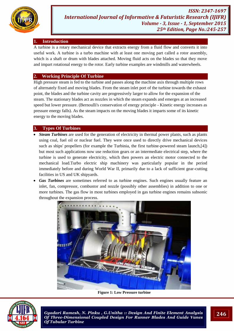
Gas Turbines are sometimes referred to as turbine engines. Such engines usually feature an
inlet, fan, compressor, combustor and nozzle (possibly other assemblies) in addition to one or
more turbines. The gas flow in most turbines employed in gas turbine engines remains subsonic
throughout the expansion process.
Figure 1: Low Pressure turbine
247
ISSN: 2347-1697 International Journal of Informative & Futuristic Research (IJIFR)
Gyadari Ramesh, N. Pinku , G.Unitha :: Design And Finite Element Analysis Of Three-Dimensional Coupled Design For Runner Blades And Guide Vanes Of Tubular Turbine
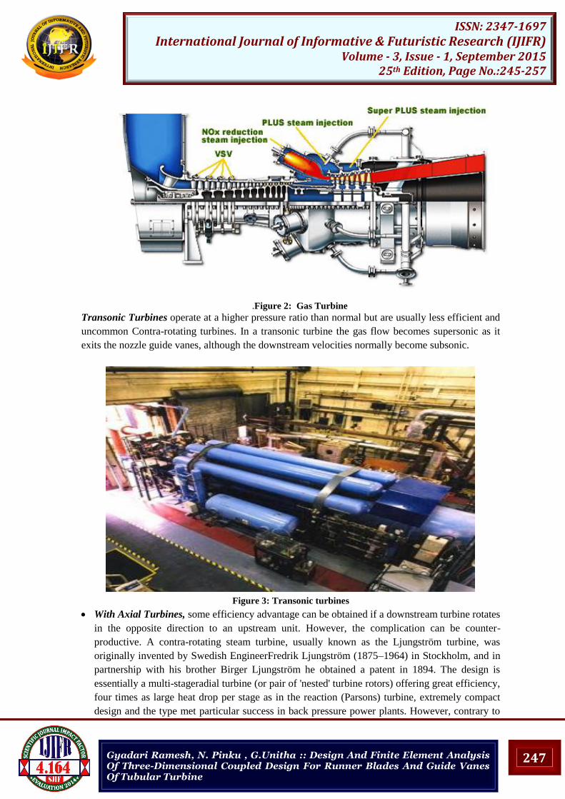
.Figure 2: Gas Turbine
Transonic Turbines operate at a higher pressure ratio than normal but are usually less efficient and
uncommon Contra-rotating turbines. In a transonic turbine the gas flow becomes supersonic as it
exits the nozzle guide vanes, although the downstream velocities normally become subsonic.
Figure 3: Transonic turbines
With Axial Turbines, some efficiency advantage can be obtained if a downstream turbine rotates
in the opposite direction to an upstream unit. However, the complication can be counter-
productive. A contra-rotating steam turbine, usually known as the Ljungström turbine, was
originally invented by Swedish EngineerFredrik Ljungström (1875–1964) in Stockholm, and in
partnership with his brother Birger Ljungström he obtained a patent in 1894. The design is
essentially a multi-stageradial turbine (or pair of 'nested' turbine rotors) offering great efficiency,
four times as large heat drop per stage as in the reaction (Parsons) turbine, extremely compact
design and the type met particular success in back pressure power plants. However, contrary to
248
ISSN: 2347-1697 International Journal of Informative & Futuristic Research (IJIFR)
Gyadari Ramesh, N. Pinku , G.Unitha :: Design And Finite Element Analysis Of Three-Dimensional Coupled Design For Runner Blades And Guide Vanes Of Tubular Turbine
other designs, large steam volumes are handled with difficulty and only a combination with axial
flow turbines (DUREX) admits the turbine to be built for power greater than ca 50 MW. In
marine applications only about 50 turbo-electric units were ordered (of which a considerable
amount were finally sold to land plants) during 1917-19, and during 1920-22 a few turbo-
mechanic not very successful units were sold.[5] Only a few turbo-electric marine plants were
still in use in the late 1960s (ss Ragne, ss Regin) while most land plants remain in use 2010.
Figure 4: Sketch illustrating principle of C.R.G.T. Engine
Statorless Turbine: Multi-stage turbines have a set of static (meaning stationary) inlet guide
vanes that direct the gas flow onto the rotating rotor blades. In a stator-less turbine the gas flow
exiting an upstream rotor impinges onto a downstream rotor without an intermediate set of stator
vanes (that rearrange the pressure/velocity energy levels of the flow) being encountered.
Ceramic Turbine: Conventional high-pressure
turbine blades (and vanes) are made from nickel
based alloys and often utilize intricate internal
air-cooling passages to prevent the metal from
overheating. In recent years, experimental
ceramic blades have been manufactured and
tested in gas turbines, with a view to increasing
rotor inlet temperatures and/or, possibly,
eliminating air cooling. Ceramic blades are more
brittle than their metallic counterparts, and carry
a greater risk of catastrophic blade failure. This
has tended to limit their use in jet engines and gas
turbines to the stator (stationary) blades.
Figure 5: Ceramic turbine NTU made
249
ISSN: 2347-1697 International Journal of Informative & Futuristic Research (IJIFR)
Gyadari Ramesh, N. Pinku , G.Unitha :: Design And Finite Element Analysis Of Three-Dimensional Coupled Design For Runner Blades And Guide Vanes Of Tubular Turbine
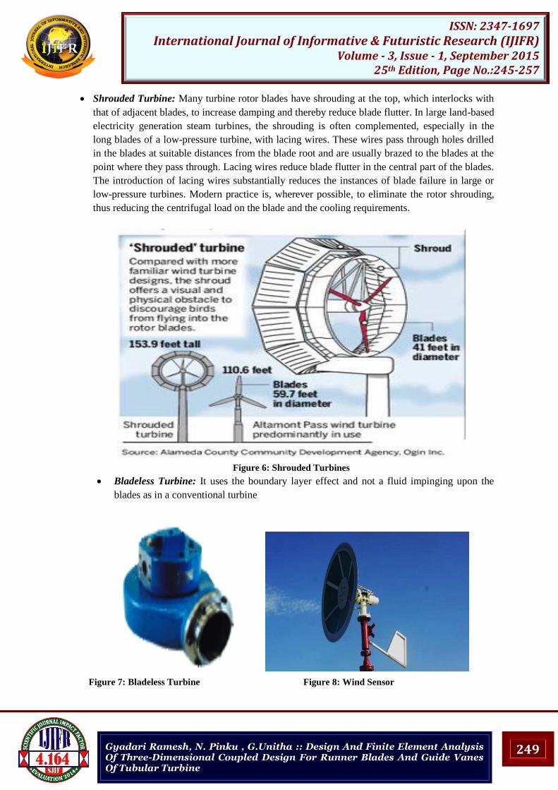
Shrouded Turbine: Many turbine rotor blades have shrouding at the top, which interlocks with
that of adjacent blades, to increase damping and thereby reduce blade flutter. In large land-based
electricity generation steam turbines, the shrouding is often complemented, especially in the
long blades of a low-pressure turbine, with lacing wires. These wires pass through holes drilled
in the blades at suitable distances from the blade root and are usually brazed to the blades at the
point where they pass through. Lacing wires reduce blade flutter in the central part of the blades.
The introduction of lacing wires substantially reduces the instances of blade failure in large or
low-pressure turbines. Modern practice is, wherever possible, to eliminate the rotor shrouding,
thus reducing the centrifugal load on the blade and the cooling requirements.
Figure 6: Shrouded Turbines
Bladeless Turbine: It uses the boundary layer effect and not a fluid impinging upon the
blades as in a conventional turbine
Figure 7: Bladeless Turbine Figure 8: Wind Sensor
250
ISSN: 2347-1697 International Journal of Informative & Futuristic Research (IJIFR)
Gyadari Ramesh, N. Pinku , G.Unitha :: Design And Finite Element Analysis Of Three-Dimensional Coupled Design For Runner Blades And Guide Vanes Of Tubular Turbine
4. Overview Of Water Turbines
Peloton Turbine: Peloton turbine is a type of impulse water turbine. The Peloton wheel is
an impulse type water turbine. It was invented by Lester Allan Pelton in the 1870s. The Pelton
wheel extracts energy from the impulse of moving water, as opposed to water's dead weight like the
traditional overshot water wheel. Many variations of impulse turbines existed prior to Pelton's
design, but they were less efficient than Pelton's design. Water leaving those wheels typically still
had high speed, carrying away much of the dynamic energy brought to the wheels. Pelton's paddle
geometry was designed so that when the rim ran at half the speed of the water jet, the water left the
wheel with very little speed; thus his design extracted almost all of the water's impulse energy—
which allowed for a very efficient turbine.
Function: Nozzles direct forceful, high-speed streams of water against a rotary series of spoon-
shaped buckets, also known as impulse blades, which are mounted around the circumferential rim
of a drive wheel—also called a runner (see photo, 'Old Pelton wheel..'). As the water jet impinges
upon the contoured bucket-blades, the direction of water velocity is changed to follow the contours
of the bucket. Water impulse energy exerts torque on the bucket-and-wheel system, spinning the
wheel; the water stream itself does a "u-turn" and exits at the outer sides of the bucket, decelerated
to a low velocity. In the process, the water jet's momentum is transferred to the wheel and thence to
a turbine. Thus, "impulse" energy does work on the turbine. For maximum power and efficiency,
the wheel and turbine system is designed such that the water jet velocity is twice the velocity of the
rotating buckets. A very small percentage of the water jet's original kinetic energywill remain in the
water, which causes the bucket to be emptied at the same rate it is filled, (see conservation of mass)
and thereby allows the high-pressure input flow to continue uninterrupted and without waste of
energy. Typically two buckets are mounted side-by-side on the wheel, which permits splitting the
water jet into two equal streams (see photo). This balances the side-load forces on the wheel and
helps to ensure smooth, efficient transfer of momentum of the fluid jet of water to the turbine
wheel. Because water and most liquids are nearly incompressible, almost all of the available energy
is extracted in the first stage of the hydraulic turbine. Therefore, Pelton wheels have only one
turbine stage, unlike gas turbines that operate with compressible fluid.
Figure 9: Peloton Turbine
251
ISSN: 2347-1697 International Journal of Informative & Futuristic Research (IJIFR)
Gyadari Ramesh, N. Pinku , G.Unitha :: Design And Finite Element Analysis Of Three-Dimensional Coupled Design For Runner Blades And Guide Vanes Of Tubular Turbine
Francis Turbine: Francis turbine, a type of widely used water turbine. Francis turbine is one
having a runner with buckets, usually nine or more to which the water enters the turbine in a
radial direction with respect to shaft. The Francis turbine is a type of water turbine that was
developed by James B. Francis in Lowell, Massachusetts.[1]
It is an inward-flow reaction
turbine that combines radial and axial flow concepts. Francis turbines are the most common water
turbine in use today. They operate in a water head from 40 to 600 m (130 to 2,000 ft) and are
primarily used for electrical power production. The electric generator which most often use this
type of turbine, have a power output which generally ranges just a few kilowatts up to 800 MW,
though mini-hydro installations may be lower. Penstock (input pipes) diameters are between 3
and 33 feet (0.91 and 10.06 metres). The speed range of the turbine is from 83 to 1000 rpm.
Wicket gates around the outside of the turbine's rotating runner control the rate of water flow
through the turbine for different power production rates. Francis turbines are almost always
mounted with the shaft vertical to keep water away from the attached generator and to facilitate
installation and maintenance access to it and the turbine.
Figure 10: Francis Turbine
Kaplan Turbine: Kaplan turbine, a variation of the Francis Turbine. The Kaplan turbine is a
propeller-type water turbine which has adjustable blades. It was developed in 1913 by the
Austrian professor Viktor Kaplan, who combined automatically adjusted propeller blades with
automatically adjusted wicket gates to achieve efficiency over a wide range of flow and water
level. The Kaplan turbine was an evolution of the Francis turbine. Its invention allowed efficient
power production in low-head applications that was not possible with Francis turbines. The head
ranges from 10–70 meters and the output from 5 to 200 MW. Runner diameters are between 2
and 11 meters. The range of the turbine rotation is from 79 to 429 rpm. The Kaplan turbine
installation believed to generate the most power from its nominal head of 34.65m is as of 2013
the Tocoma Power Plant (Venezuela) Kaplan turbine generating 235MW with each of ten 4.8m
diameter runners. Kaplan turbines are now widely used throughout the world in high-flow, low-
head power production.
252
ISSN: 2347-1697 International Journal of Informative & Futuristic Research (IJIFR)
Gyadari Ramesh, N. Pinku , G.Unitha :: Design And Finite Element Analysis Of Three-Dimensional Coupled Design For Runner Blades And Guide Vanes Of Tubular Turbine
Figure 11:Keplan Turbine
Turgo Turbine: Turgo turbine, a modified form of the Pelton wheel. The Turgo turbine is
an impulse water turbine designed for medium head applications. Operational Turgo Turbines
achieve efficiencies of about 87%. In factory and lab tests Turgo Turbines perform with
efficiencies of up to 90%. It works with net heads between 15 and 300 m. Developed in 1919
by Gilkes as a modification of the Pelton wheel, the Turgo has some advantages over Francis and
Pelton designs for certain applications. First, the runner is less expensive to make than a Pelton
wheel. Second, it doesn't need an airtight housing like the Francis. Third, it has higher specific
speed and can handle a greater flow than the same diameter Pelton wheel, leading to reduced
generator and installation cost. Turgos operate in a head range where the Francis and Pelton
overlap. While many large Turgo installations exist, they are also popular for small hydro where
low cost is very important. Like all turbines with nozzles, blockage by debris must be prevented
for effective operation.
Figure 12: Turgo Turbine
253
ISSN: 2347-1697 International Journal of Informative & Futuristic Research (IJIFR)
Gyadari Ramesh, N. Pinku , G.Unitha :: Design And Finite Element Analysis Of Three-Dimensional Coupled Design For Runner Blades And Guide Vanes Of Tubular Turbine
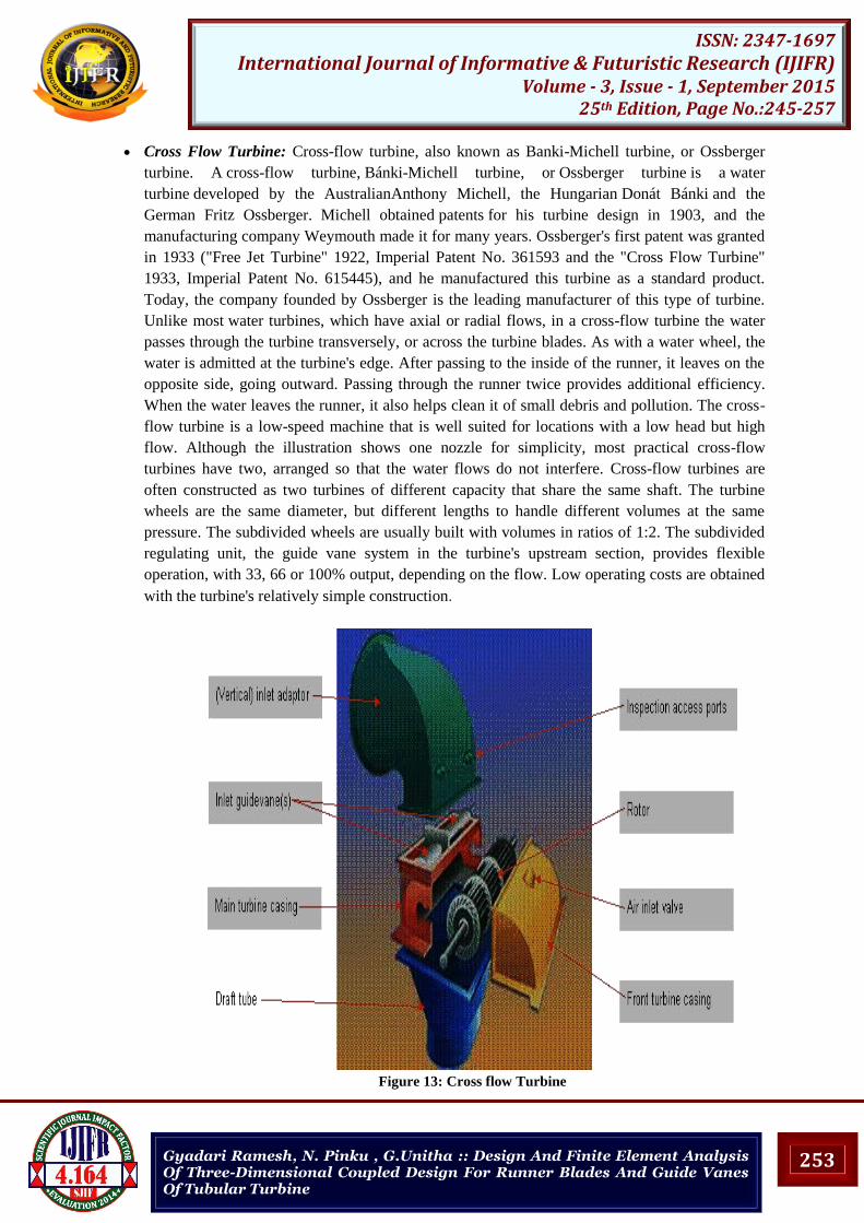
Cross Flow Turbine: Cross-flow turbine, also known as Banki-Michell turbine, or Ossberger
turbine. A cross-flow turbine, Bánki-Michell turbine, or Ossberger turbine is a water
turbine developed by the AustralianAnthony Michell, the Hungarian Donát Bánki and the
German Fritz Ossberger. Michell obtained patents for his turbine design in 1903, and the
manufacturing company Weymouth made it for many years. Ossberger's first patent was granted
in 1933 ("Free Jet Turbine" 1922, Imperial Patent No. 361593 and the "Cross Flow Turbine"
1933, Imperial Patent No. 615445), and he manufactured this turbine as a standard product.
Today, the company founded by Ossberger is the leading manufacturer of this type of turbine.
Unlike most water turbines, which have axial or radial flows, in a cross-flow turbine the water
passes through the turbine transversely, or across the turbine blades. As with a water wheel, the
water is admitted at the turbine's edge. After passing to the inside of the runner, it leaves on the
opposite side, going outward. Passing through the runner twice provides additional efficiency.
When the water leaves the runner, it also helps clean it of small debris and pollution. The cross-
flow turbine is a low-speed machine that is well suited for locations with a low head but high
flow. Although the illustration shows one nozzle for simplicity, most practical cross-flow
turbines have two, arranged so that the water flows do not interfere. Cross-flow turbines are
often constructed as two turbines of different capacity that share the same shaft. The turbine
wheels are the same diameter, but different lengths to handle different volumes at the same
pressure. The subdivided wheels are usually built with volumes in ratios of 1:2. The subdivided
regulating unit, the guide vane system in the turbine's upstream section, provides flexible
operation, with 33, 66 or 100% output, depending on the flow. Low operating costs are obtained
with the turbine's relatively simple construction.
Figure 13: Cross flow Turbine
254
ISSN: 2347-1697 International Journal of Informative & Futuristic Research (IJIFR)
Gyadari Ramesh, N. Pinku , G.Unitha :: Design And Finite Element Analysis Of Three-Dimensional Coupled Design For Runner Blades And Guide Vanes Of Tubular Turbine
Wind Turbine: Wind turbine. These normally operate as a single stage without nozzle and
interstage guide vanes. An exception is the Éolienne Bollée, which has a stator and a rotor.
A wind turbine is a popular name for a device that converts kinetic energy from the wind into
electrical power. Technically, there is no turbine used in the design, but the term appears to have
migrated from parallel hydroelectric technology (rotary propeller). The correct description for this
type of machine would be aerofoil-powered generator. The result of over a millennium of
windmill development and modern engineering, today's wind turbines are manufactured in a wide
range of vertical and horizontal axis types. The smallest turbines are used for applications such as
battery charging for auxiliary power for boats or caravans or to power traffic warning signs.
Slightly larger turbines can be used for making contributions to a domestic power supply while
selling unused power back to the utility supplier via the electrical grid. Arrays of large turbines,
known as wind farms, are becoming an increasingly important source of renewable energy and
are used by many countries as part of a strategy to reduce their reliance on fossil fuels.
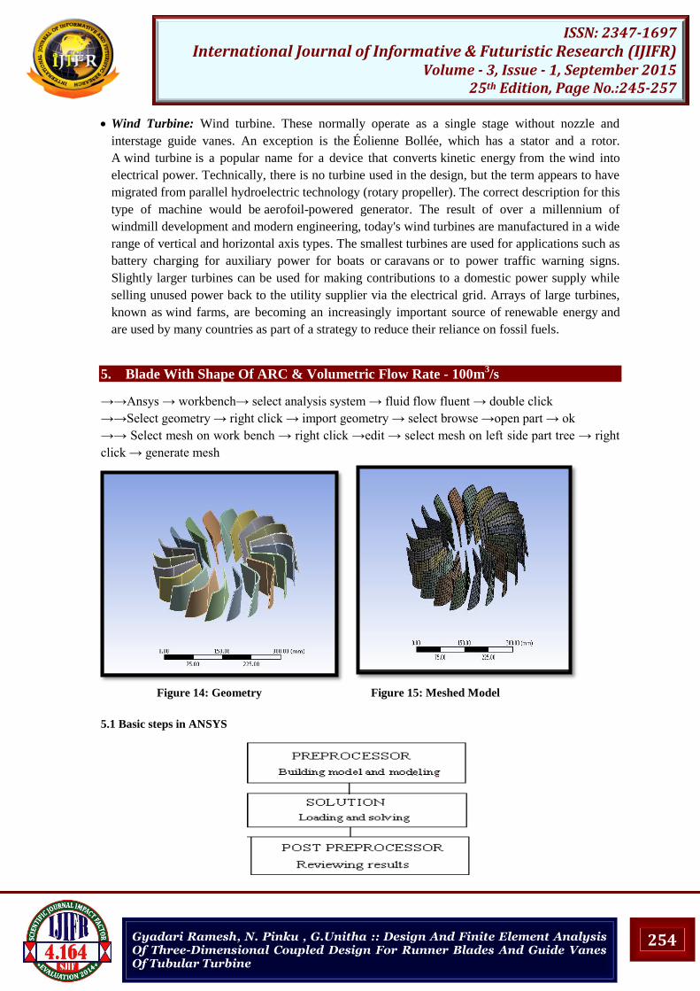
5. Blade With Shape Of ARC & Volumetric Flow Rate - 100m3/s
Gyadari Ramesh, N. Pinku , G.Unitha :: Design And Finite Element Analysis Of Three-Dimensional Coupled Design For Runner Blades And Guide Vanes Of Tubular Turbine
5.1.2 Pre-Processing (Defining the Problem): The major steps in pre-processing are given below
Define key points/lines/ areas/volumes.
Define element type and material/geometric properties
Mesh lines/ areas/volumes as required.
The amount of detail required will depend on the dimensionality of the analysis (i.e., 1D, 2D,
axi-symmetric, 3D).
5.13 Solution (Assigning Loads, Constraints, And Solving): Here the loads (point or pressure),
constraints (translational and rotational) are specified and finally solve the resulting set of
equations.
5.1.4 Post Processing: In this stage, further processing and viewing of the results can be done such
as:
Lists of nodal displacements
Element forces and moments
Deflection plots
Stress contour diagrams
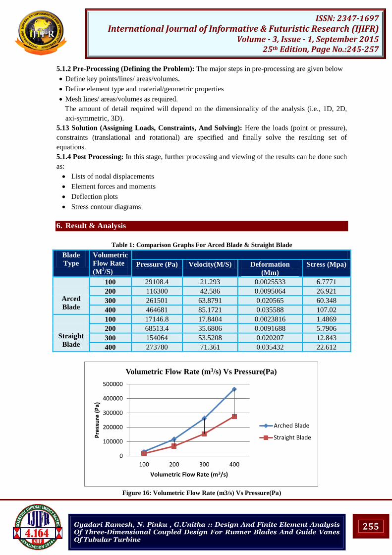
6. Result & Analysis
Table 1: Comparison Graphs For Arced Blade & Straight Blade
Blade
Type
Volumetric
Flow Rate
(M3/S)
Pressure (Pa) Velocity(M/S) Deformation
(Mm)
Stress (Mpa)
Arced
Blade
100 29108.4 21.293 0.0025533 6.7771
200 116300 42.586 0.0095064 26.921
300 261501 63.8791 0.020565 60.348
400 464681 85.1721 0.035588 107.02
Straight
Blade
100 17146.8 17.8404 0.0023816 1.4869
200 68513.4 35.6806 0.0091688 5.7906
300 154064 53.5208 0.020207 12.843
400 273780 71.361 0.035432 22.612
Figure 16: Volumetric Flow Rate (m3/s) Vs Pressure(Pa)
0
100000
200000
300000
400000
500000
100 200 300 400
Pre
ssu
re (
Pa)
Volumetric Flow Rate (m3/s)
Volumetric Flow Rate (m3/s) Vs Pressure(Pa)
Arched Blade
Straight Blade
256
ISSN: 2347-1697 International Journal of Informative & Futuristic Research (IJIFR)
Gyadari Ramesh, N. Pinku , G.Unitha :: Design And Finite Element Analysis Of Three-Dimensional Coupled Design For Runner Blades And Guide Vanes Of Tubular Turbine
Figure 17: Volumetric Flow Rate (m
3/s) Vs Velocity(m/s)
Figure 18: Volumetric Flow Rate (m3/s) Vs Deformation (mm)
Figure 19: Volumetric Flow Rate (m3/s) Vs Stress(MPa)
0
20
40
60
80
100
100 200 300 400
Ve
loci
ty (
m/s
)
Volumetric Flow Rate (m3/s)
Volumetric Flow Rate (m3/s) Vs Velocity(m/s)
Arched
Straight
0
0.005
0.01
0.015
0.02
0.025
0.03
0.035
0.04
100 200 300 400
De
form
atio
n (
mm
)
Volumetric Flow Rate (m3/s)
Volumetric Flow Rate (m3/s) Vs Deformation (mm)
Arched
Straight
0
20
40
60
80
100
120
100 200 300 400
Stre
ss (
MP
a)
Volumetric Flow Rate (m3/s)
Volumetric Flow Rate (m3/s) Vs Stress(MPa)
Arched
Straight
257
ISSN: 2347-1697 International Journal of Informative & Futuristic Research (IJIFR)
Gyadari Ramesh, N. Pinku , G.Unitha :: Design And Finite Element Analysis Of Three-Dimensional Coupled Design For Runner Blades And Guide Vanes Of Tubular Turbine
7. Conclusions
The original Tubular turbine has runner with arced blade shape. In this thesis, the shape of the blade
is modified to straight and the comparison is made between arced and straight blade of the runner.
The runner is designed in Pro/Engineer 3D modeling software. Fluid – Solid interaction is
performed to simulate behavior of fluid flow on runner blade with different volume flow inlets (i.e.,
100, 200, 300 & 400m3/s) and thereby determining stresses due to pressure developed from fluid
flow. Stainless Steel is used as the runner blade material for static analysis and fluid is water.By
observing the CFD analysis results, the pressures developed are less for straight blade is less than
the arched blade. The pressure is almost reduced by 40% for all volumetric flow rates. But the
velocity is reduced by 0.19% for straight blade than arched blade. The stresses are reduced by 78%
for all volumetric flow rates for straight blades than arched blades. So it can be concluded that
using straight blades is better than arched blades.
8. Future Scope
The effect of cavitation is not considered in the present thesis. Cavitation occurs in the flow of
water when, owing to regions of high-flow velocity, the local static pressure decreases below the
vapour pressure and vapour bubbles appear. The effects of cavitation are harmful, both on
performance and on erosion of material. This work can be extended to avoid cavitation effect by
analyzing in the CFD.
9. References 1. LI Fengchao, FAN Honggang, WANG Zhengwei, CHEN Naixiang-Three-dimensional coupled
design for runner blades and guide vanes of tubular turbine by
2. P Drtina and M Sallaberger Sulzer Hydro AG, Zu¨rich -Hydraulic turbines—basic principles and