Page 1
3
DESIGN, CONSTRUCTION AND COMMISSIONING OF PHOTOBIOREACTOR
FOR PRODUCTION OF MICROALGAE FOR BIODIESEL
NUR ATTEYA BINTI AIDILFITRI
A project report submitted in partial fulfillment of the requirements for the award of the
Bachelor degree of Chemical Engineering (Biotechnology)
Faculty of Chemical and Natural Resources Engineering
University Malaysia Pahang
DECEMBER 2010
Page 2
v
ABSTRACT
Oil can potentially be produced by microalgae which then can be converted into
biodiesel. The objective of this research is to design, construct and commission a solar
receiver which is the part of the photobioreactor which will enable the operator to
monitor and control mixing and the level of dissolved CO2 in the medium and as well
expose it to sunlight for the microalgae to undergo photosynthesis. The construction
consist of two stages namely the first stage on the construction of the vertical airlift
photobioreactor which will provide the flow, and the second stage on the construction of
the horizontal solar receiver photobioreactor which will enable the microalgae to tap on
the sunlight for photosynthesis. The work in this thesis only focused on the second
stage. For the second stage, the most important objective is that the flow is turbulent.
We can manipulate it by varying the flow rate of air sparged through the airlift
bioreactor. There were three steps that have been done to complete this research which
is the design, construction and commissioning processes. The design of photobioreactor
has been used to construct the solar receiver and the support structure of the solar
receiver. For the commissioning process, black dye has been used to determine the
pattern of the flow in the solar receiver. Initially, the pressure of the sparging air used is
4, 8, 12, 16 and 20 psi respectively. For the 4 psi, the flow of the dye is slow and it
dispersed in the water too slowly. For the pressure 8 and 12 psi, both the flow is
moderate. For the 8 psi, the dye dispersed slowly while for the 12 psi the dye dispersed
quickly. At 16 psi, the flow was fast and the dye dispersed immediately. At 20 psi, it
took the shortest time to complete the cycle but there was overflow in the degassing
zone. Thus, the best pressure that can be used to complete the cycle with the shortest
time is at 16 psi which is equal to 110.32 kPa and the flow is turbulent. All the research
objectives have been achieved.
Page 3
vi
ABSTRAK
Mikroalga berpotensi untuk menghasilkan minyak dan boleh ditukar menjadi
biodiesel. Tujuan kajian ini dijalankan adalah untuk merancang, membina dan menguji
penerima suria yang merupakan sebahagian daripada fotobioreaktor yang akan
membolehkan operator untuk memantau dan mengawal pencampuran dan tahap CO2
terlarut dalam media dan juga membenarkan sinar matahari menembusi reactor
untuk mikroalga menjalani fotosintesis. Pembinaan terdiri dari dua tahap iaitu tahap
pertama pada pembangunan penaik udara menegak akan memberikan aliran, dan tahap
kedua pada pembangunan fotobioreaktor penerima horizontal suria yang akan
membolehkan mikroalga untuk menerima sinar matahari untuk fotosintesis. Kajian
dalam tesis ini tertumpu pada tahap kedua. Untuk tahap kedua, tujuan yang paling
penting adalah menghasilkan aliran yang.bergelora. Kita dapat memanipulasinya dengan
memvariasikan kelajuan aliran udara melalui bioreaktor penaik udara. Ada tiga langkah
yang telah dilakukan untuk menyelesaikan kajian ini iaitu rekaan, pembinaan dan proses
menguji. Design fotobioreaktor telah digunakan untuk membina penerima suria dan
struktur sokongan untuk penerima suria. Untuk proses komisioning, pewarna hitam telah
digunakan untuk menentukan pola aliran dalam penerima suria. Awalnya, tekanan udara
Sparging digunakan adalah 4, 8, 12, 16 dan 20 psi masing-masing. Untuk 4 psi, aliran
pewarna lambat dan terdispersi dalam air terlalu lambat.Waktu yang diperlukan untuk
menyelesaikan kitaran itu ialah 474 saat. Untuk tekanan 8, 12, 16 dan 20 psi, masa yang
diambil ialah 210, 165, 140 dan 119 saat. Dengan demikian, tekanan terbaik yang boleh
digunakan untuk melengkapkan kitaran dengan waktu terpendek ialah 16 psi yang sama
dengan 110,32 kPa Dengan ini, semua tujuan kajian telah dicapai.
Page 4
vii
TABLE OF CONTENTS
CHAPTER SUBJECT PAGE
TITLE i
DECLARATION OF ORIGINALITY AND ii
EXCLUSIVENESS
DEDICATION iii
ACKNOWLEDGEMENT iv
ABSTRACT v
ABSTRAK vi
TABLE OF CONTENTS vii
LIST OF TABLES x
LIST OF FIGURES xi
LIST OF APPENDICES xii
LIST OF SYMBOLS/ABBREVIATION xiii
1 INTRODUCTION
1.1 Background of study 1-2
1.2 Problem statement 2
1.3 Research Objectives 3
1.4 Scopes of research 3
Page 5
viii
2 LITERATURE REVIEW
2.1 Photobioreactor (PBR) design
2.1.1 Solar Receiver 4-7
2.1.2 Airlift system 8-9
2.2 Requirement for microalgae growth
2.2.1 Light source and carbon dioxide 10-11
2.3 Comparison of raceways and tubular PBR 11-12
2.4 Potential of microalgal biodiesel 13-14
3 METHODOLOGY
3.1 Introduction 15
3.2 Design of solar receiver 15
3.3 Construction of solar receiver 16
3.4 Combining 16
3.5 Testing and Commissioning 16-17
4 RESULTS AND DISCUSSION
4.1 Introduction 18
4.2 Results and Discussion
4.2.1 Photobioreactor Design (solar receiver) 18-19
4.2.2 Construction of solar receiver 20
4.2.3 Combining and testing the PBR 20-23
5 CONCLUSIONS AND RECOMMENDATIONS
5.1 Conclusion 24
5.2 Recommendation 24
Page 6
ix
REFERENCES 25-27
APPENDIX A 28-40
APPENDIX B 41-45
Page 7
x
LIST OF TABLES
TABLE NO TITLE PAGE
2.1 Comparison photobioreactor 11
and raceways
2.2 Comparison of some sources of 13
Biodiesel
4.1 Result of testing process 22
Page 8
xi
LIST OF FIGURES
FIGURE TITLE PAGE
2.1 Example of photobioreactor 7
2.2 The gas liquid separator 8
4.1 Schematic diagram, of solar receiver 19
4.2 Graph of pressure of air sparged vs time 22
Page 9
xii
LIST OF APPENDICES
APPENDIX NO TITLE PAGE
A.1 Materials 28-30
A.2 Personal Protective Equipment 30-32
A.3 Construction Process 32-34
A.4 Combining Process 35-36
A.5 Testing and commissioning 37-40
B.1 Theory Calculation 41
B.2 Results of the testing 42-45
Page 10
xiii
LIST OF SYMBOLS/ABBREVIATION
Ar Cross sectional area of riser, m2
Ad Cross sectional area of downcomer, m2
Cf Fanning friction factor
g Gravitational acceleration, m s-1
hr Height of riser, m
KB Frictional loss coefficient for the bottom zone of the airlift
KT Frictional loss coefficient for the top of the airlift
Leq Equivalent length of solar loop, m
PBR Photobioreactor
UL Superficial liquid velocity in the tube, m s-1
𝜀r Gas holdup in the riser
𝜀d Gas holdup in the downcomer
𝜇L Viscosity of the culture broth, kg m-1
.s-1
𝜌 Density of the fluid, kg m-3
∅ Solar tube diameter, m
Page 11
1
CHAPTER 1
INTRODUCTION
1.1 Research Background
Biofuels from microalgae have a great potential to meet future challenges of
carbon dioxide neutral energy supply and storage. The climate change and shortage of
resources call for a substantial change of global power supply from fossil to regenerative
energy sources. For electricity generation, powerful techniques such as wind,
photovoltaic or geothermal energy exist already today. However, currently, electricity
accounts only for a minor fraction of the global energy demand. Two thirds of the
world’s final energy consumption is covered by oil, coal and gas (IEA 2009)
Microalgae are one of the groups of photosynthetic, heterotrophic organisms
which have an extraordinary potential for cultivation as energy crops. They can be
cultivated under difficult agro climatic conditions and are able to produce a wide range
of commercially interesting by products such as fats, oils, sugars and functional
bioactive compounds. As a group, they are of particular interest in the development of
future renewable energy scenarios. Certain microalgae are effective in the production of
hydrogen and oxygen through the process of bio-photolysis while others naturally
manufacture hydrocarbon which are suitable for direct use as high energy liquid fuels.
Page 12
2
A photobioreactor is a bioreactor which incorporates some types of light source
to provide photonic energy input into the reactor. Photobioreactor also has been used
widely in culturing microalgae. An open pond also could be seen as photobioreactor but
mostly the term photobioreactor only refers to closed system. System closed to the
environment having no direct exchange of gases and contaminants with the
environment. In this research, we will study the effect of airlift system height and the
mixing of microalgae.
In an optimal system where no other factors limit, the light availability
determines the rate of photosynthesis and productivity. However, excessive light can be
harmful and is known to produce a photo inhibitory response (Bannister, 1979; Aiba,
1982).We will also need to design an effective CO2 sparger so that we can monitor and
study the optimum carbon dioxide supply for microalgae’s growth. The effect of this
study will help to make an upscale design of photobioreactors that will save amount of
space of lands or ponds.
1.2 Problem Statement
Nowadays, there are many water pollution occurred in Malaysia. Poor sewage
treatment has been blamed as being one of the causes of corals slowly dying in the sea
off the east coast of peninsular Malaysia, as algae was found to have smothered some
reef, indicating nutrient pollution. Thus, to overcome the problem, photobioreactor was
designed to produce the optimum growth of the microalgae itself. For the optimum
growth of the microalgae several parameter has to be manipulated, that is:
a) Pressure of air sparged from the air compressor.
b) Turbulent flow in the solar receiver part to mix the microalgae.
Page 13
3
1.3 Research Objectives
The objectives of the research are to:
a) Design and construct the photobioreactor for the production of microalgae
b) Commissioning and testing the photobioreactor by manipulating the pressure
of air sparged through the airlift sytem to create the turbulent flow.
1.4 Scope of Research
The scope of the research is to achieve the research objectives. The construction
and commissioning process of the photobioreactor have been done in Engineering
Workshop FKKSA UMP. For this research, the scopes of study are:
a) Photobioreactor design
b) Manipulated variable
i) Mixing
ii) Pressure of air sparged.
c) Relationship between the PBR design and manipulated variable.
Page 14
4
CHAPTER 2
LITERATURE REVIEW
2.1 Photobioreactor Design
2.1.1 Tubular Solar Receiver
Tubular photobioreactors that circulate the culture by using an airlift device are
especially attractive for several reasons: circulation is achieved without moving parts
and this provides a robust culture system with a reduced potential for contamination
(Chisti,1989); the cell damage associated with mechanical pumping is avoided
(Chisti,1999;Vandanjon et al.,1999); and the airlift device combines the function of a
pump and a gas exchanger that removes the oxygen produced by photosynthesis
(Camacho Rubio et al.,1999). Continuous removal of oxygen is essential, as excessive
dissolved oxygen in the broth inhibits photosynthesis.
Unlike open raceways, photobioreactors permit essentially single-species culture
of microalgae for prolonged durations. Photobioreactors have been successfully used for
producing large quantities of microalgal biomass (Molina Grima et al., 1999; Tredici,
1999; Pulz, 2001; Carvalho et al., 2006). A tubular photobioreactor consists of straight
transparent tubes that are usually made of plastic or glass. This tubular array, or the solar
collector,is where the sunlight is captured The solar collector tubes are generally 0.1m
or less in diameter. Tube diameter is limited because light does not penetrate too deeply
in the dense culture broth that is necessary for ensuring a high biomass productivity of
Page 15
5
the photobioreactor. The solar collector is oriented to maximize sunlight capture
(Molina Grima et al., 1999; Sánchez Mirón et al., 1999). In addition, the design must
ensure that the flow in the solar tube is turbulent (i.e. the minimum Reynolds number
should exceed 3000) so that the cells do not stagnate in the dark interior of the tube. At
the same time, the dimensions of the fluid microeddies should always exceed those of
the algal cells. So that turbulence associated damage is prevented.
For maximizing the biomass productivity, the irradiance on the surface of the
solar tubes must be maximized. This external surface irradiance depends mainly on the
solar irradiance, which is a function of the location and the weather conditions
(Incropera and Thomas, 1978). For a given location and weather, the geometric
arrangement of the solar receiver tubes also determines the irradiance on the surface of
the tubes and so does the albedo effect (irradiance enhancement because of reflectance)
of the surrounding. The geometric distribution of the tube over a given land surface
controls the extent of mutual shading.
To know the flow is turbulent or not, there is the equation which is the equation
to calculate the Reynolds number, Re. The Reynolds number, Re can be calculated as
follows:
(1)
Where UL is the velocity of the liquid in the tubes, 𝜌 is the fluid’s density, ∅ is the
diameter of the tube and the 𝜇Lis the viscosity of the fluid.
Page 16
6
The liquid flow in the solar receiver is driven by the airlift pump. For water- like
fluid such as the microalgal broth, the induced flow velocity depends mainly on the
geometric configuration of the circulation loop and the differences in gas hold up in the
riser and the downcomer zones of the airlift column. This relationship has been
established (Chisti, 1989) to be:
(2)
where the KT and KB are the frictional loss coefficient for the top and the bottom
connecting sections respectively of the airlift loop. Eq (2) is based on principles of
energy conservation and it has been repeatedly validated for a broad range of scales and
configurations of airlift devices (Chisti, 1989). In eq (2) hr is the height of the riser
section, Ar and Ad are the cross-sectional areas of the riser and downcomer, 𝜀r is the gas
holdup in the riser and 𝜀d is the holdup in the downcomer. Generally, KT is much
smaller than KB, hence KT can be neglected. (Chisti, 1989). This is particularly true of
the loop configuration used for photobioreactor. Because of the bottom section of the
loop is simply continuous pipe( the solar receiver), the frictional loss coefficient KB can
be approximated as
(3)
where Cf the fanning factor established with Blasius equation (eq 4) and Leq is the
equivalent length of the loop. The latter is the straight tube length L plus additional
length that provides the same pressure drop as the bends and valves in the loop
combined.
(4)
Page 17
7
In addition, the photobioreactor geometry must maximize capture of sunlight
while minimizing the land surface occupied (Molina et al., 2001). Effects of tube length,
flow velocity, the airlift column height, and the geometric configuration of the solar
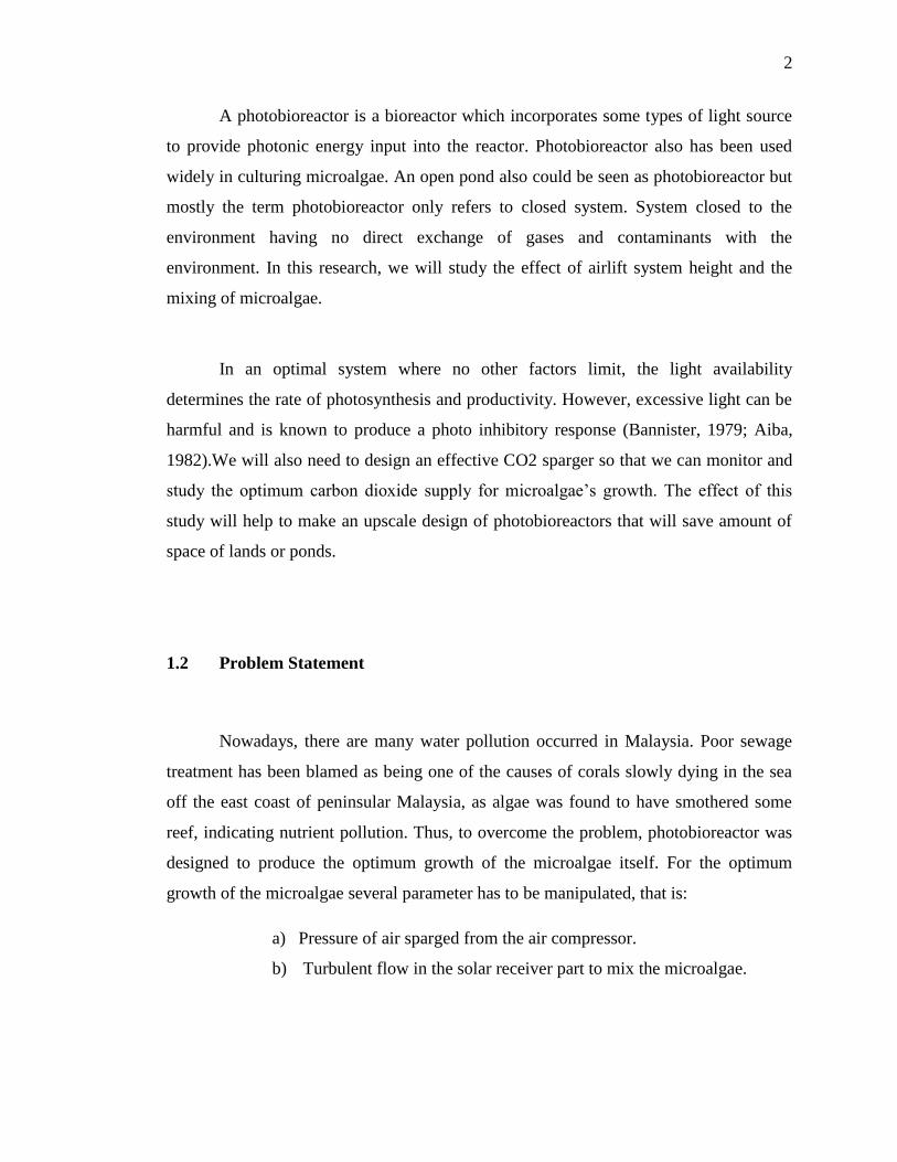
receiver on various performance parameters have been discussed. Figure 2.1 shows the
example of microalgae photobioreactor that consists of airlift and its solar collector.
Figure 2.1: Example of photobioreactor
Photobioreactor tubes operated with high-density culture for attaining high
productivity inevitably contain a photo limited central dark zone and a relatively better
lit peripheral zone (Molina Grima et al., 1999, 2001). Light intensity in the photo limited
zone is lower than the saturation light level.
Page 18
8
2.1.2 Airlift system
In an airlift driven tubular photobioreactor, the recirculation velocity of the
culture and oxygen removal characteristics are closely linked. The culture performance
is critically dependent on attaining an optimal design that provides the requisite flow
and gas exchange. The airlift column circulates the culture through the solar collector
tubing where most of the photosynthesis occurs. The oxygen produced by
photosynthesis accumulates in the broth until the fluid returns to the airlift zone where
the accumulated oxygen is stripped by air. A gas–liquid separator in the upper part of
the airlift column prevents gas bubbles from recirculating into the solar collector. The
solar loop is designed to efficiently collect the solar radiation, minimize resistance to
flow, and occupy minimal area to reduce the demand for land. In addition, the diameter
of the solar tubing is selected so that the volume of the dark zone (i.e. one with light
intensity below saturation) is kept to a minimum. Also, the interchange of fluid between
the light and the dark zones in the solar loop must be sufficiently rapid that element of
fluid does not reside continuously in the dark zone for long (Ogbanna and Tanaka,
1997).
Figure 2.2: The gas liquid separator
Page 19
9
The head zone of the airlift column (Figure 2.2) was designed for almost
complete separation of the gas from the liquid, before the broth recirculated into the
solar collector. Complete disengagement of gas meant that the driving force for liquid
circulation was the maximum attainable for any aeration rate in the airlift riser. To
achieve effective separation of gas and liquid, the distance between the entrance and the
exit of the degasser should be such that the smallest bubbles have a sufficient time to
disengage before the fluid enters the down comer (Chisti and Moo-Young, 1993).
The airlift device fulfills two needs: the circulation of the fluid through the solar
loop and stripping of oxygen from the broth. The volume of the broth in the airlift
device needs to be small compared to the volume in the solar loop so that the cells spend
as much time as possible in the relatively better illuminated loop. In this work, the riser
and down comer tubes of the airlift device were vertical extensions of the ends of the
solar loop. The volume in the gas liquid separator was minimized by reducing the
spacing between the parallel walls to the width of the riser (or the down comer) tube
(Fig.2.2).
An efficient large scale PBR has yet to be developed [Ogbanna and Tanaka,
1997]. This has left commercial production of algae to open ponds. Open ponds do not
provide conditions necessary for high density algal biomass production because of
diurnal and annual variation in light intensity and temperature. Chen (1996) states that
enclosed PBRs have the following advantages over open pond production.
1. Better control of algal culture
2. Large surface-to-volume ratio
3. Better control of gas transfer
4. Reduction in evaporation of growth medium
5. More uniform temperature
6. Better protection from outside contamination
7. Higher algal cell densities are possible.
Page 20
10
2.2 Requirement for microalgae growth
2.2.1 Light source and Carbon dioxide
Availability and intensity of light are the major factors controlling productivity
of photosynthetic cultures (Lee and Low, 1992; Pulz and Scheinben-bogen, 1998).
Photosynthesis is a process comprising two steps, light reactions that only occur when
the cells are illuminated, and carbon fixation reactions, also known as dark reactions,
that occur both in the presence and absence of light. Thus in the first step the cells
transform light energy into chemical energy, which is stored in high-energy compounds
for later use in the carbon-fixation reactions (Iverson, 2006). The use of these
photosynthetic pathways in environmental engineering processes requires the use of
solar energy so as to develop clean technology processes (Essam et al., 2007). Thus the
cells use the light energy by way of exergonic reactions, producing energy that is used in
the synthesis of compounds as from carbon dioxide fixation by way of endergonic
reactions (Horton et al., 1994).
In photosynthetic cultures, the amount of light energy received and stored by the
cells has a direct relationship with the carbon fixation capacity, consequently
determining the productivity in biomass and cell growth rate. In nature, light energy is
available in a discontinuous way, since the light varies from day to night. Such
considerations are relevant in carbon sequestration processes in photobioreactors, since
the viability of these systems requires the use of solar energy for photosynthesis.
Page 21
11
Carbon dioxide is the usual carbon source for photosynthetic culture of
microalgae. Carbon dioxide is typically supplied by continuous or intermittent injection
of the gas at the beginning of a tubular solar receiver. As the carbon is consumed,
oxygen is ultimately produced by photolysis of water. The generated oxygen is released
into the culture fluid. The fluid in a tubular solar receiver in plug flow; hence, the
concentration of carbon dioxide reflected in the culture pH changes (Livansky and
Bartos, 1986) along the tube and so does the concentration of oxygen (Weissman et al.,
1988).
2.3 Comparison of photobioreactor and raceways
There is the comparison between photobioreactor and the raceways. The table
2.1 below shows that the comparison of both of it.
Table 2.1: Comparison of photobioreactor and raceways methods
Page 22
12
This comparison is for an annual production level of 100t of biomass in both
cases. Both production methods consume an identical amount of carbon dioxide (Table
2.1), if losses to atmosphere are disregarded. The production methods in Table 2.1 are
compared for optimal combinations of biomass productivity and concentration that have
been actually achieved in large-scale photobioreactors and raceways. Photobioreactors
provide much greater oil yield per hectare compared with raceway ponds (Table 2.1).
This is because the volumetric biomass productivity of photo-bioreactors is more than
13 fold greater in comparison with raceway ponds (Table 2.1).
Both raceway and photobioreactor production methods are technically feasible.
Production facilities using photobioreactors and raceway units of dimensions similar to
those in (Table 2.1) have indeed been used extensively in commercial operations (Terry
and Raymond, 1985; Molina Grima, 1999; Molina Grima et al.,1999; Tredici,1999;
Pulz,2001; Lorenz and Cysewski,2003; Spolaore et al.,2006).
Recovery of microalgal biomass from the broth is necessary for extracting the
oil. Biomass is easily recovered from the broth by filtration, centrifugation, and other
means (Molina Grima et al., 2003). Cost of biomass recovery can be significant.
Biomass recovery from photobioreactor cultured broth costs only a fraction of the
recovery cost for broth produced in raceways. This is because the typical biomass
concentration that is produced in photobioreactors is nearly 30 times the biomass
concentration that is generally obtained in raceways (Table 2.1). Thus, in comparison
with raceway broth, much smaller volume of the photobioreactor broth needs to be
processed to obtain a given quantity of biomass.
Page 23
13
2.4 Potential of microalgal biodiesel
Table 2.2: Comparison of some sources of biodiesel
In view of Table 2.2, microalgae appear to be the only source of biodiesel that
has the potential to completely displace fossil diesel. Unlike other oil crops, microalgae
grow extremely rapidly and many are exceedingly rich in oil. Microalgae commonly
double their biomass within 24h. Biomass doubling times during exponential growth are
commonly as short as 3.5h. Oil content in microalgae can exceed 80% by weight of dry
biomass (Metting, 1996; Spolaore et al., 2006).
Microalgae with high oil productivities are desired for producing biodiesel.
Depending on species, microalgae produce many different kinds of lipids, hydrocarbons
and other complex oils (Banerjee et al., 2002; Metzger and Largeau, 2005; Guschina and
Harwood, 2006). Not all algal oils are satisfactory for making biodiesel, but suitable oils
occur commonly. Using microalgae to produce biodiesel will not compromise
production of food, fodder and other products derived from crops.
Page 24
14
Potentially, instead of microalgae, oil producing heterotrophic microorganisms
(Ratledge, 1993; Ratledge and Wynn, 2002) grown on a natural organic carbon source
such as sugar, can be used to make biodiesel; however, heterotrophic production is not
as efficient as using photosynthetic microalgae. This is because the renewable organic
carbon sources required for growing heterotrophic microorganisms are produced
ultimately by photosynthesis, usually in crop plants.
Page 25
15
CHAPTER 3
METHODOLOGY
3.1 Introduction
In this research, the photobioreactor had two parts which are airlift system and
solar receiver. For airlift system, it has been done by another student (Syafiq, 2010).
Thus, in this section, the steps to fabricate the solar receiver are explained.This section
had been divided into three categories that is the design, construction and lastly the
commissioning process.
3.2 Design of solar receiver
For the design of solar receiver which is a part of photobioreactor, the materials
that have been used were polyvinylchloride (PVC) plastic, comprising of transparent
and non-transparent (grey) PVC. Fittings have also been used to connect the series of
pipe with diameters of 10 cm and 6cm. Besides that, the dimension of the solar receiver
was determined.