Operation Electric, Heated, Plural Component Proportioner For spraying polyurethane foam and polyurea coatings. Not for use in explosive atmospheres. See page 3 for model information, including maxi- mum working pressure and approvals. Important Safety Instructions Read all warnings and instructions in this manual. Save these instructions. TI10953a Model E-XP1 Shown 312065F
Transcript
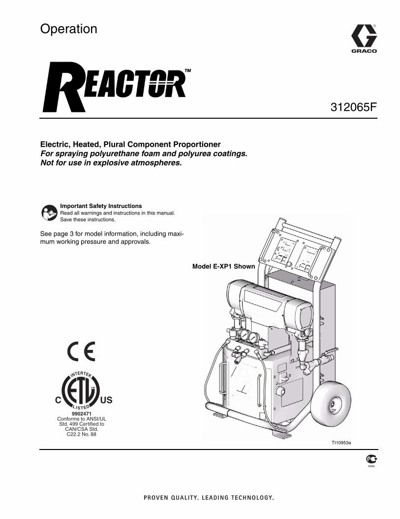
Operation
Electric, Heated, Plural Component ProportionerFor spraying polyurethane foam and polyurea coatings. Not for use in explosive atmospheres.
See page 3 for model information, including maxi-mum working pressure and approvals.
Important Safety InstructionsRead all warnings and instructions in this manual. Save these instructions.
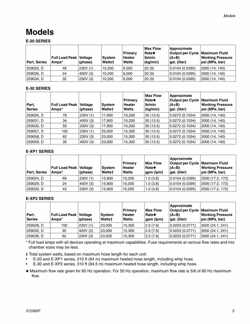
* Full load amps with all devices operating at maximum capabilities. Fuse requirements at various flow rates and mix chamber sizes may be less.
† Total system watts, based on maximum hose length for each unit:• E-20 and E-XP1 series, 210 ft (64 m) maximum heated hose length, including whip hose.• E-30 and E-XP2 series, 310 ft (94.5 m) maximum heated hose length, including whip hose.
◆ Maximum flow rate given for 60 Hz operation. For 50 Hz operation, maximum flow rate is 5/6 of 60 Hz maximum flow.
The following manuals are shipped with the Reactor™ Proportioner. Refer to these manuals for detailed equip-ment information.
Order Part 15M334 for a compact disk of Reactor manu-als translated in several languages.
Manuals are also available at www.graco.com.
Related ManualsThe following manuals are for accessories used with the
Reactor™.
Order Part 15M334 for a compact disk of Reactor manu-als translated in several languages.
Reactor Hydraulic Proportioner
Part Description
312066 Reactor Electric Proportioner, Repair-Parts Manual (English)
Reactor Electrical Diagrams
Part Description
312067 Reactor Electric Proportioner, Electrical Diagrams (English)
Proportioning Pump
Part Description
309577 Electric Reactor Displacement Pump Repair-Parts Manual (English)
Reactor Data Reporting Kit
Part Description
309867 Instruction-Parts Manual (English)
Fusion Spray Gun
Part Description
309550 Instruction-Parts Manual (English)
Heated Hose
Part Description
309572 Instruction-Parts Manual (English)
Circulation and Return Tube Kit
Part Description
309852 Instruction-Parts Manual (English)
Rupture Disk Assembly Kit
Part Description
312416 Instruction-Parts Manual (English)
Electric Reactor Installation
Part Description
310815 Instruction Manual (English)
Warnings
312065F 5
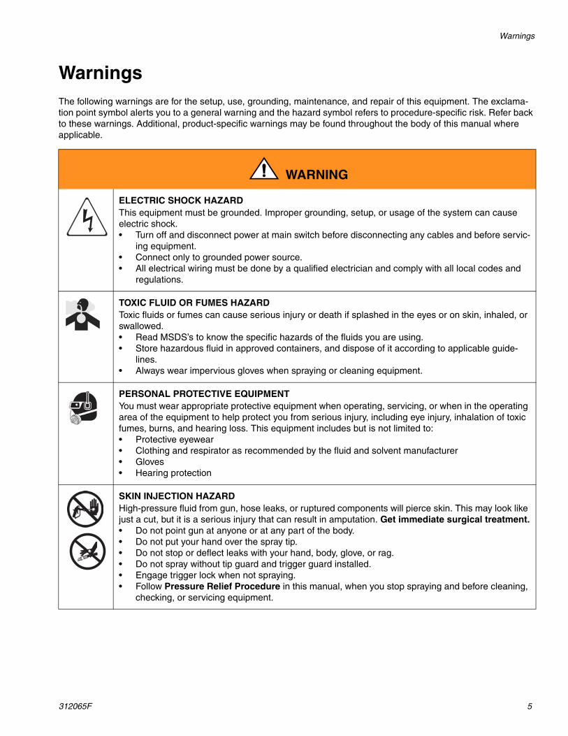
WarningsThe following warnings are for the setup, use, grounding, maintenance, and repair of this equipment. The exclama-tion point symbol alerts you to a general warning and the hazard symbol refers to procedure-specific risk. Refer back to these warnings. Additional, product-specific warnings may be found throughout the body of this manual where applicable.
WARNING
ELECTRIC SHOCK HAZARD This equipment must be grounded. Improper grounding, setup, or usage of the system can cause electric shock.• Turn off and disconnect power at main switch before disconnecting any cables and before servic-
ing equipment.• Connect only to grounded power source.• All electrical wiring must be done by a qualified electrician and comply with all local codes and
regulations.
TOXIC FLUID OR FUMES HAZARD Toxic fluids or fumes can cause serious injury or death if splashed in the eyes or on skin, inhaled, or swallowed.• Read MSDS’s to know the specific hazards of the fluids you are using.• Store hazardous fluid in approved containers, and dispose of it according to applicable guide-
lines.• Always wear impervious gloves when spraying or cleaning equipment.
PERSONAL PROTECTIVE EQUIPMENT You must wear appropriate protective equipment when operating, servicing, or when in the operating area of the equipment to help protect you from serious injury, including eye injury, inhalation of toxic fumes, burns, and hearing loss. This equipment includes but is not limited to:• Protective eyewear • Clothing and respirator as recommended by the fluid and solvent manufacturer• Gloves• Hearing protection
SKIN INJECTION HAZARD High-pressure fluid from gun, hose leaks, or ruptured components will pierce skin. This may look like just a cut, but it is a serious injury that can result in amputation. Get immediate surgical treatment.• Do not point gun at anyone or at any part of the body.• Do not put your hand over the spray tip.• Do not stop or deflect leaks with your hand, body, glove, or rag.• Do not spray without tip guard and trigger guard installed.• Engage trigger lock when not spraying.• Follow Pressure Relief Procedure in this manual, when you stop spraying and before cleaning,
checking, or servicing equipment.
Warnings
6 312065F
FIRE AND EXPLOSION HAZARD Flammable fumes, such as solvent and paint fumes, in work area can ignite or explode. To help pre-vent fire and explosion:• Use and clean equipment only in well ventilated area.• Eliminate all ignition sources; such as pilot lights, cigarettes, portable electric lamps, and plastic
drop cloths (potential static arc). • Keep work area free of debris, including solvent, rags and gasoline.• Do not plug or unplug power cords or turn lights on or off when flammable fumes are present.• Ground equipment, personnel, object being sprayed, and conductive objects in work area. See
Grounding instructions.• Use only Graco grounded hoses.• Check gun resistance daily.• If there is static sparking or you feel a shock, stop operation immediately. Do not use equip-
ment until you identify and correct the problem.• Do not flush with gun electrostatics on. Do not turn on electrostatics until all solvent is removed
from system.• Keep a working fire extinguisher in the work area.
PRESSURIZED ALUMINUM PARTS HAZARD Do not use 1,1,1-trichloroethane, methylene chloride, other halogenated hydrocarbon solvents or flu-ids containing such solvents in pressurized aluminum equipment. Such use can cause serious chem-ical reaction and equipment rupture, and result in death, serious injury, and property damage.
EQUIPMENT MISUSE HAZARD Misuse can cause death or serious injury.• This equipment is for professional use only.• Do not leave the work area while equipment is energized or under pressure. Turn off all equip-
ment and follow the Pressure Relief Procedure in this manual when equipment is not in use.• Do not operate the unit when fatigued or under the influence of drugs or alcohol.• Do not exceed the maximum working pressure or temperature rating of the lowest rated system
component. See Technical Data in all equipment manuals.• Use fluids and solvents that are compatible with equipment wetted parts. See Technical Data in
all equipment manuals. Read fluid and solvent manufacturer’s warnings. For complete informa-tion about your material, request MSDS forms from distributor or retailer.
• Check equipment daily. Repair or replace worn or damaged parts immediately with genuine manufacturer’s replacement parts only.
• Do not alter or modify equipment.• Use equipment only for its intended purpose. Call your distributor for information.• Route hoses and cables away from traffic areas, sharp edges, moving parts, and hot surfaces.• Do not kink or over bend hoses or use hoses to pull equipment.• Keep children and animals away from work area.• Comply with all applicable safety regulations.
WARNING
Warnings
312065F 7
MOVING PARTS HAZARD Moving parts can pinch or amputate fingers and other body parts.• Keep clear of moving parts.• Do not operate equipment with protective guards or covers removed.• Pressurized equipment can start without warning. Before checking, moving, or servicing equip-
ment, follow the Pressure Relief Procedure in this manual. Disconnect power or air supply.
BURN HAZARD Equipment surfaces and fluid that’s heated can become very hot during operation. To avoid severe burns, do not touch hot fluid or equipment. Wait until equipment/fluid has cooled completely.
WARNING
Isocyanate Hazard
8 312065F
Isocyanate Hazard
Material Self-ignition
Moisture Sensitivity of IsocyanatesIsocyanates (ISO) are catalysts used in two component foam and polyurea coatings. ISO will react with moisture (such as humidity) to form small, hard, abrasive crystals, which become suspended in the fluid. Eventually a film will form on the surface and the ISO will begin to gel, increasing in viscosity. If used, this partially cured ISO will reduce performance and the life of all wetted parts.
To prevent exposing ISO to moisture:
• Always use a sealed container with a desiccant dryer in the vent, or a nitrogen atmosphere. Never store ISO in an open container.
• Keep the ISO lube pump reservoir filled with Graco Throat Seal Liquid (TSL), Part 206995. The lubri-cant creates a barrier between the ISO and the atmosphere.
• Use moisture-proof hoses specifically designed for ISO, such as those supplied with your system.
• Never use reclaimed solvents, which may contain moisture. Always keep solvent containers closed when not in use.
• Never use solvent on one side if it has been contam-inated from the other side.
• Always park pumps when you shutdown, see page 26.
• Always lubricate threaded parts with Part 217374 ISO pump oil or grease when reassembling.
Keep Components A and B Separate
Foam Resins with 245 fa Blowing AgentsNew foam blowing agents will froth at temperatures above 90°F (33°C) when not under pressure, especially if agitated. To reduce frothing, minimize preheating in a circulation system.
Changing Materials• When changing materials, flush the equipment mul-
tiple times to ensure it is thoroughly clean.• Always clean the fluid inlet strainers after flushing,
see page 32.• Check with your material manufacturer for chemical
compatibility.• Most materials use ISO on the A side, but some use
ISO on the B side.• Epoxies often have amines on the B (hardener)
side. Polyureas often have amines on the B (resin) side.
Read material manufacturer’s warnings and material MSDS to know specific hazards and precautions related to isocyanates.
Prevent inhalation of isocyanate mists, vapors, and atomized particulates by providing sufficient ventila-tion in the work area. If sufficient ventilation is not available, a supplied-air respirator is required for everyone in the work area.
To prevent contact with isocyanates, appropriate per-sonal protective equipment, including chemically impermeable gloves, boots, aprons, and goggles, is also required for everyone in the work area.
Some materials may become self-igniting if applied too thickly. Read material manufacturer’s warnings and material MSDS.
The amount of film formation and rate of crystalli-zation varies depending on the blend of ISO, the humidity, and the temperature.
CAUTIONTo prevent cross-contamination of the equipment’s wetted parts, never interchange component A (isocy-anate) and component B (resin) parts.
Typical Installation, with circulation
312065F 9
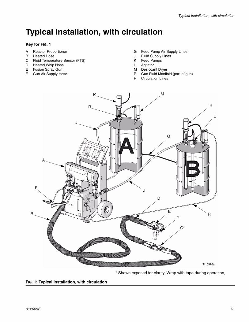
Typical Installation, with circulationKey for FIG. 1
A Reactor ProportionerB Heated HoseC Fluid Temperature Sensor (FTS)D Heated Whip HoseE Fusion Spray GunF Gun Air Supply Hose
G Feed Pump Air Supply LinesJ Fluid Supply LinesK Feed PumpsL AgitatorM Desiccant DryerP Gun Fluid Manifold (part of gun)R Circulation Lines
FIG. 1: Typical Installation, with circulation
B
A
J
F
C*
P
E
D
K M
K
L
J
G
R
R
* Shown exposed for clarity. Wrap with tape during operation,
TI10976a
Typical Installation, without circulation
10 312065F
Typical Installation, without circulationKey for FIG. 2
A Reactor ProportionerB Heated HoseC Fluid Temperature Sensor (FTS)D Heated Whip HoseE Fusion Spray GunF Gun Air Supply HoseG Feed Pump Air Supply Lines
H Waste ContainersJ Fluid Supply LinesK Feed PumpsL AgitatorM Desiccant DryerN Bleed LinesP Gun Fluid Manifold (part of gun)Q Air Filter/Separator
FIG. 2: Typical Installation, without circulation
B
A
N
J
G
F
C*
P
E
D
K M
K
L
J
G
H
* Shown exposed for clarity. Wrap with tape during operation,
TI10975a
Component Identification
312065F 11
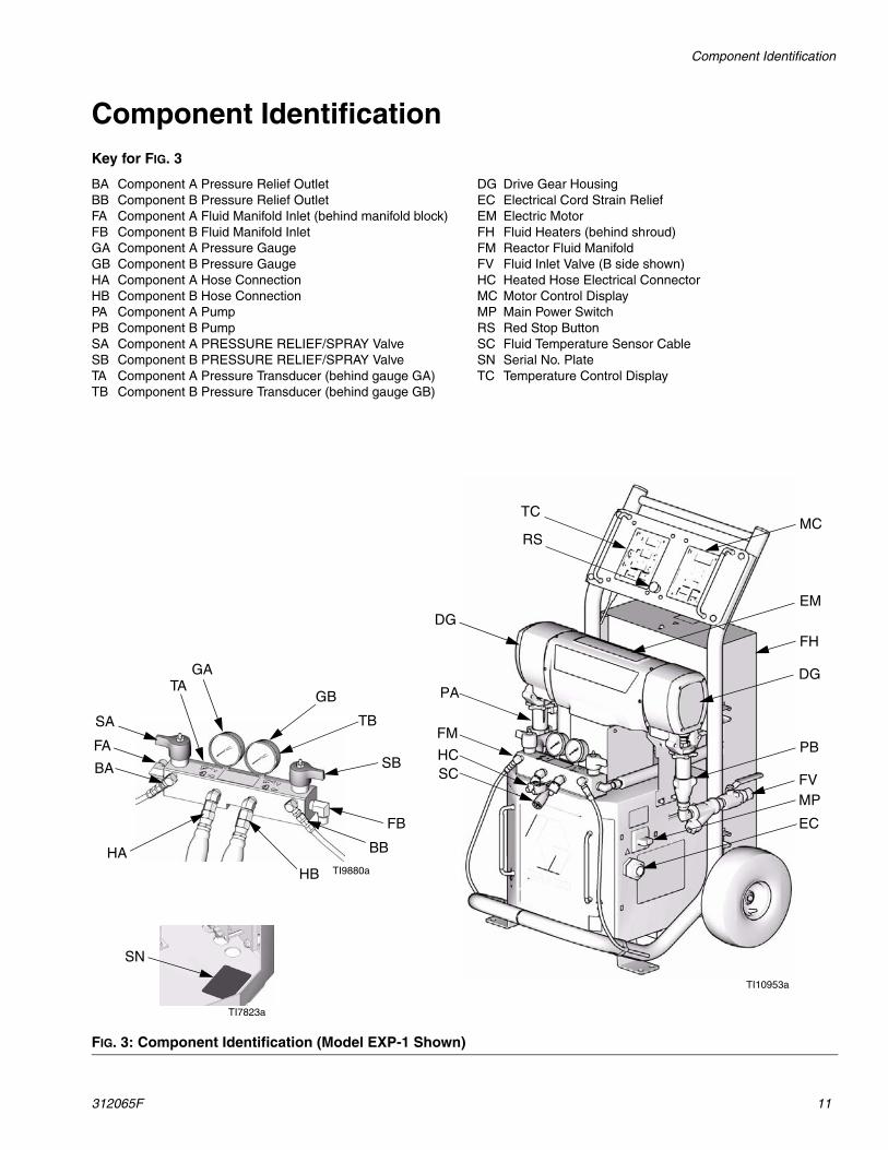
Component IdentificationKey for FIG. 3
BA Component A Pressure Relief OutletBB Component B Pressure Relief OutletFA Component A Fluid Manifold Inlet (behind manifold block)FB Component B Fluid Manifold InletGA Component A Pressure GaugeGB Component B Pressure GaugeHA Component A Hose ConnectionHB Component B Hose ConnectionPA Component A PumpPB Component B PumpSA Component A PRESSURE RELIEF/SPRAY ValveSB Component B PRESSURE RELIEF/SPRAY ValveTA Component A Pressure Transducer (behind gauge GA)TB Component B Pressure Transducer (behind gauge GB)
DG Drive Gear HousingEC Electrical Cord Strain ReliefEM Electric MotorFH Fluid Heaters (behind shroud)FM Reactor Fluid ManifoldFV Fluid Inlet Valve (B side shown)HC Heated Hose Electrical ConnectorMC Motor Control DisplayMP Main Power SwitchRS Red Stop ButtonSC Fluid Temperature Sensor CableSN Serial No. PlateTC Temperature Control Display
Main Power SwitchLocated on right side of unit, page 11. Turns Reactor
power ON and OFF . Does not turn
heater zones or pumps on.
Red Stop ButtonLocated between temperature control panel and motor
control panel, page 11. Press to shut off motor
and heater zones only. Use main power switch to shut off all power to unit.
Actual Temperature Key/LED
Press to display actual temperature.
Press and hold to display electrical current.
Target Temperature Key/LED
Press to display target temperature.
Press and hold to display heater control circuit
board temperature.
FIG. 4. Temperature Controls and Indicators
°F
°C
A
B
Zone A Arrow Keys
Zone B Arrow Keys
Hose Zone Arrow Keys
Temperature Scale Keys
Heater A On/Off Key
Heater Power Indicators
Target Temperature Key
Actual Temperature Key
Heater Displays
Hose Heater On/Off Key
Heater B On/Off Key
Temperature Controls and Indicators
312065F 13
Temperature Scale Keys/LEDs
Press or to change temperature scale.
Heater Zone On/Off Keys/LEDs
Press to turn heater zones on and off. Also clears
heater zone diagnostic codes, see page 31.
Temperature Arrow Keys
Press , then press or to adjust tem-
perature settings in 1 degree increments.
Temperature DisplaysShow actual temperature or target temperature of heater zones, depending on selected mode. Defaults to actual at startup. Range is 32-190°F (0-88°C) for A and B, 32-180°F (0-82°C) for hose.
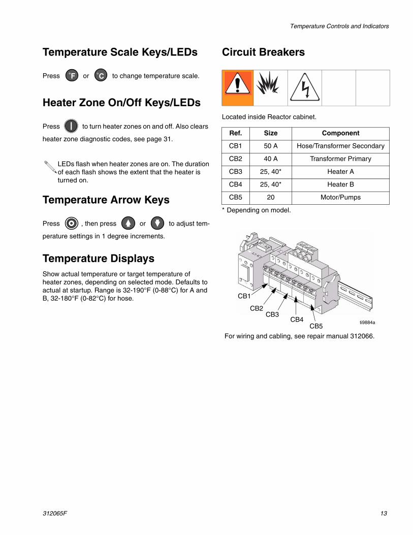
Circuit Breakers
Located inside Reactor cabinet.
* Depending on model.
LEDs flash when heater zones are on. The duration of each flash shows the extent that the heater is turned on.
°F °C
Ref. Size Component
CB1 50 A Hose/Transformer Secondary
CB2 40 A Transformer Primary
CB3 25, 40* Heater A
CB4 25, 40* Heater B
CB5 20 Motor/Pumps
ti9884a
CB3CB4
CB5
CB1
CB2
For wiring and cabling, see repair manual 312066.
Motor Controls and Indicators
14 312065F
Motor Controls and Indicators
Motor ON/OFF Key/LED
Press to turn motor ON and OFF. Also clears
some motor control diagnostic codes, see page 31.
PARK Key/LED
Press at end of day to cycle component A pump
to home position, submerging displacement rod. Trigger gun until pump stops. Once parked, motor will automati-cally shut off.
PSI/BAR Keys/LEDs
Press or to change pressure scale.
Pressure Key/LED
Press to display fluid pressure.
Cycle Count Key/LED
Press to display cycle count.
FIG. 5. Motor Controls and Indicators
PSI
BAR
ON / OFF
PARK
PSI/BAR KeysCycle Count Key
Pressure/Cycle Display
Pressure Key
Motor ON/OFF Key
PARK Key
Arrow Keys
PSI BAR
If pressures are imbalanced, display shows higher of two pressures.
To clear counter, press and hold for 3 sec.
Spray Adjustments
312065F 15
Pressure Arrow Keys
Press or to adjust fluid pressure when
motor is ON. Setpoint displays for 10 sec.
When motor is OFF, pressing will enter jog mode.
To exit jog mode, press until display shows
dashes or current pressure.
Pressure/Cycle DisplayShows fluid pressure or cycle count, depending on mode selected.
Displays J 1 through J 10 when in jog mode, page 30.
Spray AdjustmentsFlow rate, atomization, and amount of overspray are affected by four variables.
• Fluid pressure setting. Too little pressure results in an uneven pattern, coarse droplet size, low flow, and poor mixing. Too much pressure results in excessive overspray, high flow rates, difficult control, and excessive wear.
• Fluid temperature. Similar effects to fluid pressure setting. The A and B temperatures can be offset to help balance the fluid pressure.
• Mix chamber size. Choice of mix chamber is based on desired flow rate and fluid viscosity.
• Clean-off air adjustment. Too little clean-off air results in droplets building up on the front of the nozzle, and no pattern containment to control over-spray. Too much clean-off air results in air-assisted atomization and excessive overspray.
Setup
16 312065F
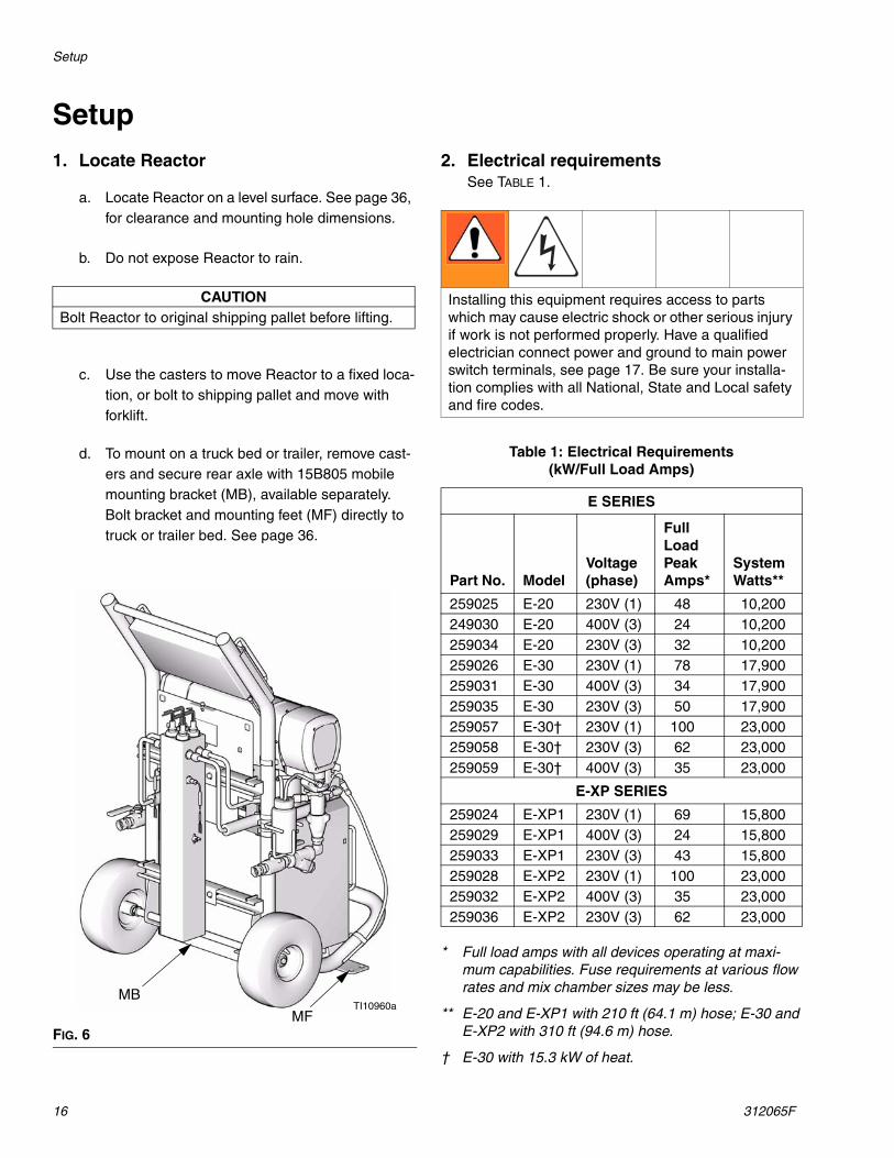
Setup1. Locate Reactor
a. Locate Reactor on a level surface. See page 36, for clearance and mounting hole dimensions.
b. Do not expose Reactor to rain.
c. Use the casters to move Reactor to a fixed loca-tion, or bolt to shipping pallet and move with forklift.
d. To mount on a truck bed or trailer, remove cast-ers and secure rear axle with 15B805 mobile mounting bracket (MB), available separately. Bolt bracket and mounting feet (MF) directly to truck or trailer bed. See page 36.
2. Electrical requirementsSee TABLE 1.
* Full load amps with all devices operating at maxi-mum capabilities. Fuse requirements at various flow rates and mix chamber sizes may be less.
** E-20 and E-XP1 with 210 ft (64.1 m) hose; E-30 and E-XP2 with 310 ft (94.6 m) hose.
† E-30 with 15.3 kW of heat.
CAUTIONBolt Reactor to original shipping pallet before lifting.
FIG. 6
TI10960aMF
MB
Installing this equipment requires access to parts which may cause electric shock or other serious injury if work is not performed properly. Have a qualified electrician connect power and ground to main power switch terminals, see page 17. Be sure your installa-tion complies with all National, State and Local safety and fire codes.
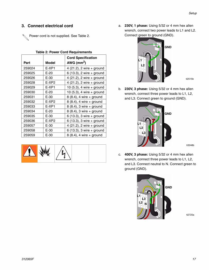
a. 230V, 1 phase: Using 5/32 or 4 mm hex allen wrench, connect two power leads to L1 and L2. Connect green to ground (GND).
b. 230V, 3 phase: Using 5/32 or 4 mm hex allen wrench, connect three power leads to L1, L2, and L3. Connect green to ground (GND).
c. 400V, 3 phase: Using 5/32 or 4 mm hex allen wrench, connect three power leads to L1, L2, and L3. Connect neutral to N. Connect green to ground (GND).
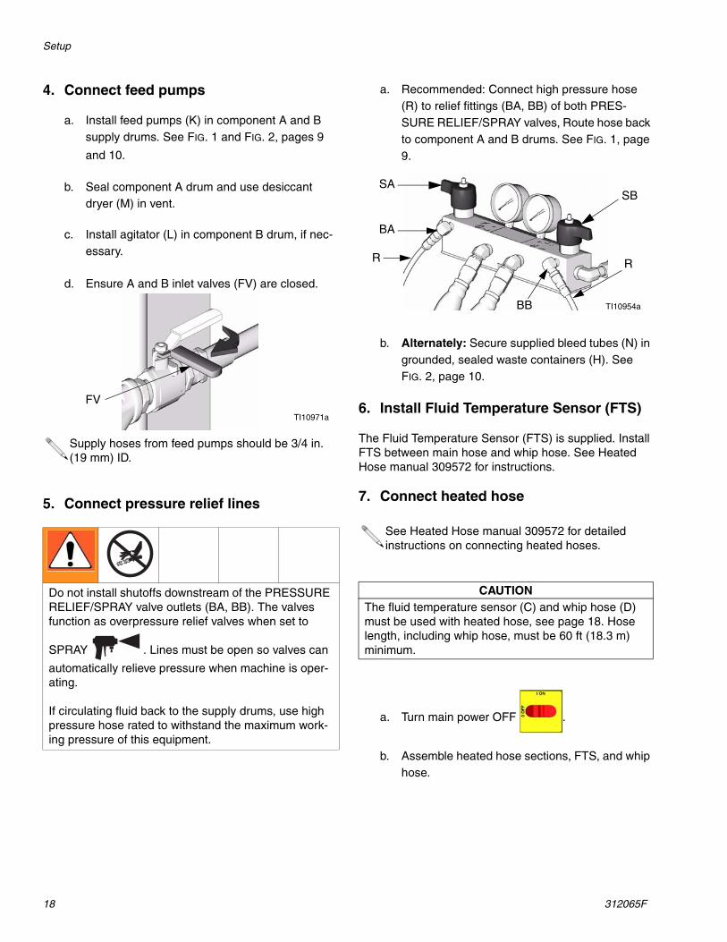
a. Install feed pumps (K) in component A and B supply drums. See FIG. 1 and FIG. 2, pages 9
and 10.
b. Seal component A drum and use desiccant dryer (M) in vent.
c. Install agitator (L) in component B drum, if nec-essary.
d. Ensure A and B inlet valves (FV) are closed.
5. Connect pressure relief lines
a. Recommended: Connect high pressure hose (R) to relief fittings (BA, BB) of both PRES-SURE RELIEF/SPRAY valves, Route hose back to component A and B drums. See FIG. 1, page 9.
b. Alternately: Secure supplied bleed tubes (N) in grounded, sealed waste containers (H). See FIG. 2, page 10.
6. Install Fluid Temperature Sensor (FTS)
The Fluid Temperature Sensor (FTS) is supplied. Install FTS between main hose and whip hose. See Heated Hose manual 309572 for instructions.
7. Connect heated hose
a. Turn main power OFF .
b. Assemble heated hose sections, FTS, and whip hose.
Supply hoses from feed pumps should be 3/4 in. (19 mm) ID.
Do not install shutoffs downstream of the PRESSURE RELIEF/SPRAY valve outlets (BA, BB). The valves function as overpressure relief valves when set to
SPRAY . Lines must be open so valves can
automatically relieve pressure when machine is oper-ating.
If circulating fluid back to the supply drums, use high pressure hose rated to withstand the maximum work-ing pressure of this equipment.
FVTI10971a
See Heated Hose manual 309572 for detailed instructions on connecting heated hoses.
CAUTIONThe fluid temperature sensor (C) and whip hose (D) must be used with heated hose, see page 18. Hose length, including whip hose, must be 60 ft (18.3 m) minimum.
TI10954a
BA
BB
R R
SBSA
Setup
312065F 19
c. Connect A and B hoses to A and B outlets on Reactor fluid manifold (FM). Hoses are color coded: red for component A (ISO), blue for com-ponent B (RES). Fittings are sized to prevent
connection errors.
d. Connect cables (Y). Connect electrical connec-tors (V). Be sure cables have slack when hose bends. Wrap cable and electrical connections with electrical tape.
8. Close gun fluid manifold valves A and B
9. Connect whip hose to gun fluid mani-fold
10.Pressure check hose
See hose manual. Pressure check for leaks. If no leaks, wrap hose and electrical connections to protect from damage.
Manifold hose adapters (HA, HB) allow use of 1/4 in. and 3/8 in. ID fluid hoses. To use 1/2 in. (13 mm) ID fluid hoses, remove adapters from fluid manifold and install as needed to connect whip hose.
FM
A
B
TI10964a
HB
HA
TI10956a
V
Y
Do not connect manifold to gun.
ti2411a
ti2417a
Setup
20 312065F
11.Ground system
a. Reactor: is grounded through power cord. See page 17.
b. Spray gun: connect whip hose ground wire to FTS, page 18. Do not disconnect wire or spray without whip hose.
c. Fluid supply containers: follow your local code.
d. Object being sprayed: follow your local code.
e. Solvent pails used when flushing: follow your local code. Use only metal pails, which are con-ductive, placed on a grounded surface. Do not place pail on a nonconductive surface, such as paper or cardboard, which interrupts grounding continuity
f. To maintain grounding continuity when flushing or relieving pressure, hold a metal part of spray gun firmly to the side of a grounded metal pail, then trigger gun.
12.Supply wet cups with Throat Seal Liquid (TSL)
a. Component A (ISO) Pump: Keep reservoir (R) filled with Graco Throat Seal Liquid (TSL), Part 206995. Wet-cup piston circulates TSL through wet-cup, to carry away isocyanate film on dis-placement rod.
b. Component B (Resin) Pump: Check felt wash-ers in packing nut/wet-cup (S) daily. Keep satu-rated with Graco Throat Seal Liquid (TSL), Part No. 206995, to prevent material from hardening on displacement rod. Replace felt washers when worn or contaminated with hardened material.
Pump rod and connecting rod move during operation. Moving parts can cause serious injury such as pinch-ing or amputation. Keep hands and fingers away from wet-cup during operation. Turn main power OFF
before filling wet cup.
FIG. 7
FIG. 8
R
TI3765a-2
S
TI3765a-1
Startup
312065F 21
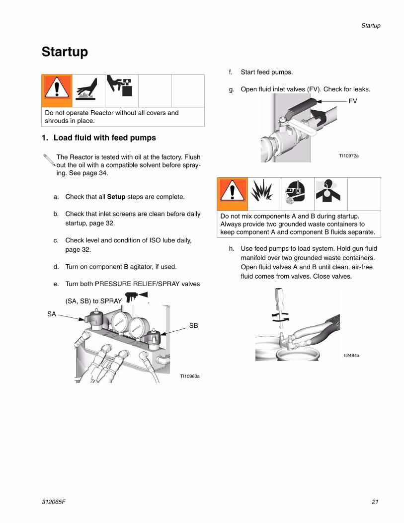
Startup
1. Load fluid with feed pumps
a. Check that all Setup steps are complete.
b. Check that inlet screens are clean before daily startup, page 32.
c. Check level and condition of ISO lube daily, page 32.
d. Turn on component B agitator, if used.
e. Turn both PRESSURE RELIEF/SPRAY valves
(SA, SB) to SPRAY .
f. Start feed pumps.
g. Open fluid inlet valves (FV). Check for leaks.
h. Use feed pumps to load system. Hold gun fluid manifold over two grounded waste containers. Open fluid valves A and B until clean, air-free fluid comes from valves. Close valves.
Do not operate Reactor without all covers and shrouds in place.
The Reactor is tested with oil at the factory. Flush out the oil with a compatible solvent before spray-ing. See page 34.
TI10963a
SA
SB
Do not mix components A and B during startup. Always provide two grounded waste containers to keep component A and component B fluids separate.
FV
TI10972a
ti2484a
Startup
22 312065F
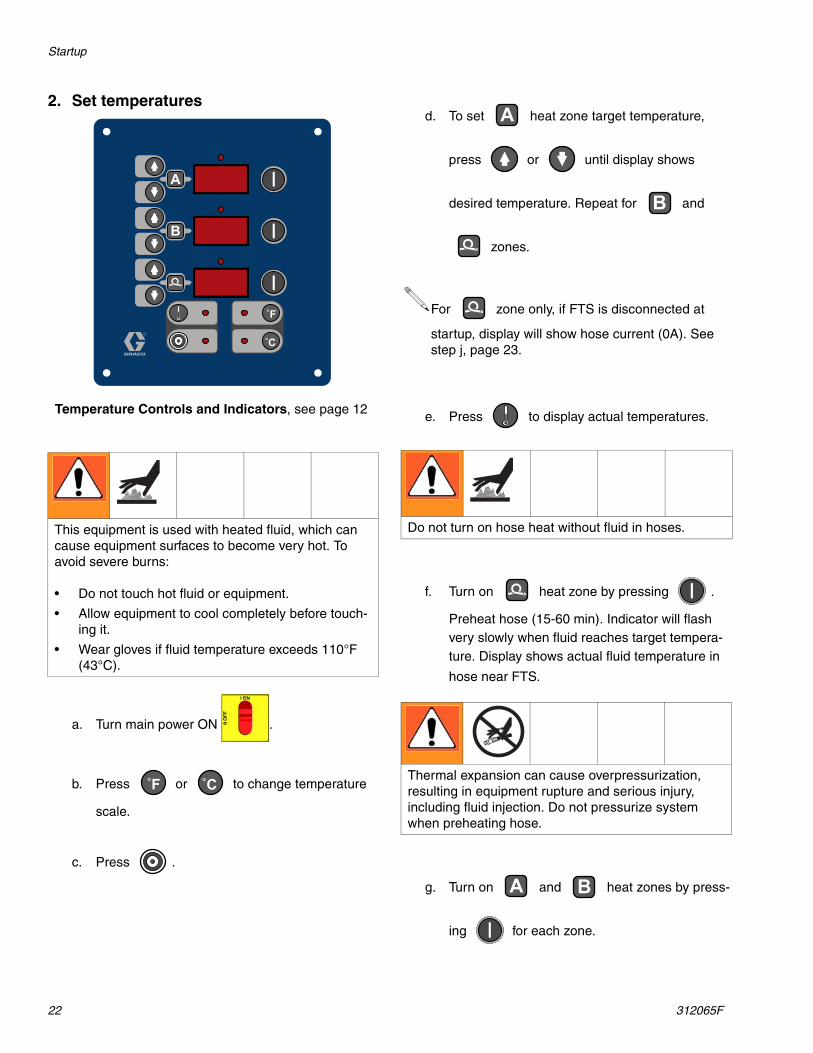
2. Set temperatures
a. Turn main power ON .
b. Press or to change temperature
scale.
c. Press .
d. To set heat zone target temperature,
press or until display shows
desired temperature. Repeat for and
zones.
e. Press to display actual temperatures.
f. Turn on heat zone by pressing .
Preheat hose (15-60 min). Indicator will flash very slowly when fluid reaches target tempera-ture. Display shows actual fluid temperature in
hose near FTS.
g. Turn on and heat zones by press-
ing for each zone.
This equipment is used with heated fluid, which can cause equipment surfaces to become very hot. To avoid severe burns:
• Do not touch hot fluid or equipment.
• Allow equipment to cool completely before touch-ing it.
• Wear gloves if fluid temperature exceeds 110°F (43°C).
°F
°C
A
B
Temperature Controls and Indicators, see page 12
°F °C
For zone only, if FTS is disconnected at
startup, display will show hose current (0A). See step j, page 23.
Do not turn on hose heat without fluid in hoses.
Thermal expansion can cause overpressurization, resulting in equipment rupture and serious injury, including fluid injection. Do not pressurize system when preheating hose.
A
B
A B
Startup
312065F 23
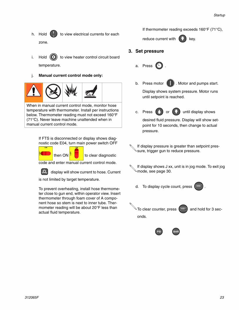
h. Hold to view electrical currents for each
zone.
i. Hold to view heater control circuit board
temperature.
j. Manual current control mode only:
If FTS is disconnected or display shows diag-nostic code E04, turn main power switch OFF
then ON to clear diagnostic
code and enter manual current control mode.
display will show current to hose. Current
is not limited by target temperature.
To prevent overheating, install hose thermome-ter close to gun end, within operator view. Insert thermometer through foam cover of A compo-nent hose so stem is next to inner tube. Ther-mometer reading will be about 20°F less than actual fluid temperature.
If thermometer reading exceeds 160°F (71°C),
reduce current with key.
3. Set pressure
a. Press .
b. Press motor . Motor and pumps start.
Display shows system pressure. Motor runs until setpoint is reached.
c. Press or until display shows
desired fluid pressure. Display will show set-point for 10 seconds, then change to actual pressure.
d. To display cycle count, press .
When in manual current control mode, monitor hose temperature with thermometer. Install per instructions below. Thermometer reading must not exceed 160°F (71°C). Never leave machine unattended when in manual current control mode.
If display pressure is greater than setpoint pres-sure, trigger gun to reduce pressure.
If display shows J xx, unit is in jog mode. To exit jog mode, see page 30.
To clear counter, press and hold for 3 sec-
onds.
PSI BAR
Spraying
24 312065F
Spraying
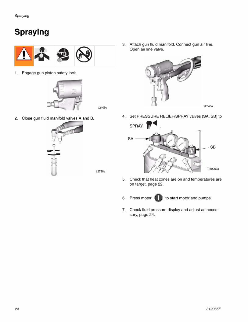
1. Engage gun piston safety lock.
2. Close gun fluid manifold valves A and B.
3. Attach gun fluid manifold. Connect gun air line. Open air line valve.
4. Set PRESSURE RELIEF/SPRAY valves (SA, SB) to
SPRAY .
5. Check that heat zones are on and temperatures are on target, page 22.
6. Press motor to start motor and pumps.
7. Check fluid pressure display and adjust as neces-sary, page 24.
ti2409a
ti2728a
ti2543a
TI10963a
SA
SB
Spraying
312065F 25
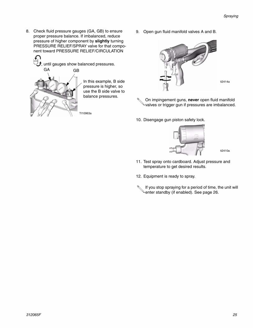
8. Check fluid pressure gauges (GA, GB) to ensure proper pressure balance. If imbalanced, reduce pressure of higher component by slightly turning PRESSURE RELIEF/SPRAY valve for that compo-nent toward PRESSURE RELIEF/CIRCULATION
, until gauges show balanced pressures.
9. Open gun fluid manifold valves A and B.
10. Disengage gun piston safety lock.
11. Test spray onto cardboard. Adjust pressure and temperature to get desired results.
12. Equipment is ready to spray.
In this example, B side pressure is higher, so use the B side valve to balance pressures.
TI10963a
GA GB
On impingement guns, never open fluid manifold valves or trigger gun if pressures are imbalanced.
If you stop spraying for a period of time, the unit will enter standby (if enabled). See page 26.
ti2414a
ti2410a
Shutdown
26 312065F
Shutdown
1. Shut off , , and heat zones.
2. Park pumps.
a. Press .
b. Trigger gun until pump A stops in the retracted position and the pressure of both pumps bleeds down.
3. Turn main power OFF .
4. Relieve pressure, page 27.
A B
Pressure Relief Procedure
312065F 27
Pressure Relief Procedure
1. Relieve pressure in gun and perform gun shutdown procedure. See gun manual.
2. Close gun fluid manifold valves A and B.
3. Shut off feed pumps and agitator, if used.
4. Turn PRESSURE RELIEF/SPRAY valves (SA, SB)
to PRESSURE RELIEF/CIRCULATION . Route fluid to waste containers or supply tanks. Ensure gauges drop to 0.
5. Engage gun piston safety lock.
6. Disconnect gun air line and remove gun fluid mani-fold.
ti2421a
TI10955a
SA
SB
ti2409a
ti2554a
Fluid Circulation
28 312065F
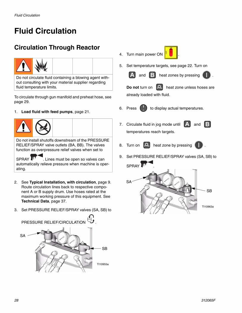
Fluid Circulation
Circulation Through Reactor
To circulate through gun manifold and preheat hose, see page 29.
1. Load fluid with feed pumps, page 21.
2. See Typical Installation, with circulation, page 9. Route circulation lines back to respective compo-nent A or B supply drum. Use hoses rated at the maximum working pressure of this equipment. See Technical Data, page 37.
3. Set PRESSURE RELIEF/SPRAY valves (SA, SB) to
PRESSURE RELIEF/CIRCULATION .
4. Turn main power ON .
5. Set temperature targets, see page 22. Turn on
and heat zones by pressing .
Do not turn on heat zone unless hoses are
already loaded with fluid.
6. Press to display actual temperatures.
7. Circulate fluid in jog mode until and
temperatures reach targets.
8. Turn on heat zone by pressing .
9. Set PRESSURE RELIEF/SPRAY valves (SA, SB) to
SPRAY .
Do not circulate fluid containing a blowing agent with-out consulting with your material supplier regarding fluid temperature limits.
Do not install shutoffs downstream of the PRESSURE RELIEF/SPRAY valve outlets (BA, BB). The valves function as overpressure relief valves when set to
SPRAY . Lines must be open so valves can automatically relieve pressure when machine is oper-ating.
TI10955a
SA
SB
A B
A B
TI10963a
SA
SB
Fluid Circulation
312065F 29
Circulation Through Gun Manifold
Circulating fluid through the gun manifold allows rapid preheating of hose.
1. Install gun fluid manifold (P) on Part 246362 acces-sory circulation kit (CK). Connect high pressure cir-culation lines (R) to circulation manifold.
2. Route circulation lines back to respective compo-nent A or B supply drum. Use hoses rated at the maximum working pressure of this equipment. See Typical Installation, without circulation, page 10.
3. Follow Load fluid with feed pumps, page 22.
4. Turn main power ON .
5. Set temperature targets, see page 22. Turn on
, , and heat zones by pressing
.
6. Press to display actual temperatures.
7. Circulate fluid in jog mode until and
temperatures reach targets.
Do not circulate fluid containing a blowing agent with-out consulting with your material supplier regarding fluid temperature limits.
RCK
P
ti2767a
A B
A B
Jog Mode
30 312065F
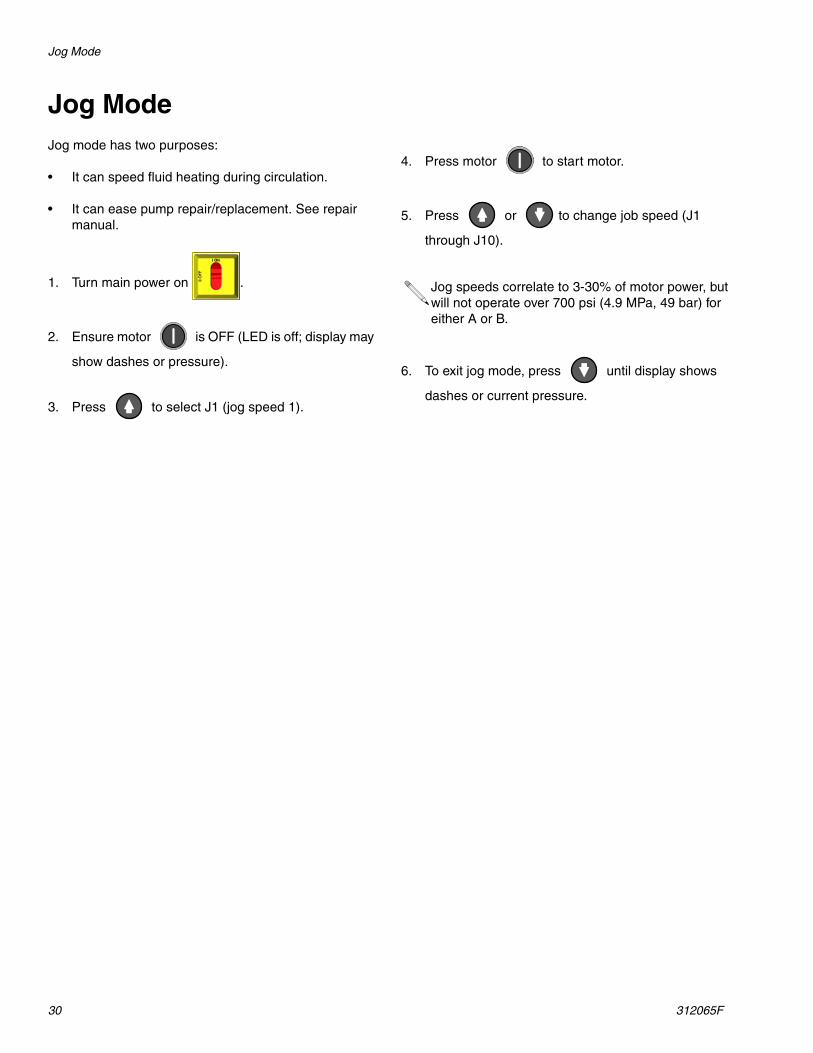
Jog ModeJog mode has two purposes:
• It can speed fluid heating during circulation.
• It can ease pump repair/replacement. See repair manual.
1. Turn main power on .
2. Ensure motor is OFF (LED is off; display may
show dashes or pressure).
3. Press to select J1 (jog speed 1).
4. Press motor to start motor.
5. Press or to change job speed (J1
through J10).
6. To exit jog mode, press until display shows
dashes or current pressure.
Jog speeds correlate to 3-30% of motor power, but will not operate over 700 psi (4.9 MPa, 49 bar) for either A or B.
Diagnostic Codes
312065F 31
Diagnostic Codes
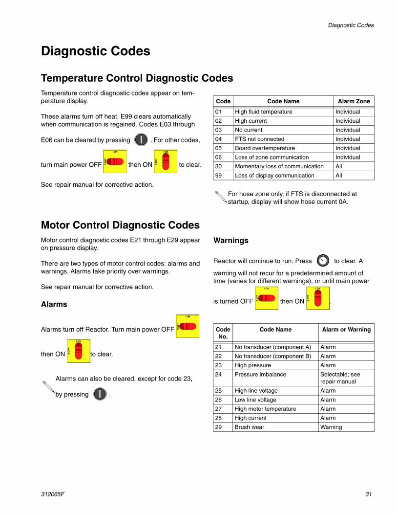
Temperature Control Diagnostic CodesTemperature control diagnostic codes appear on tem-perature display.
These alarms turn off heat. E99 clears automatically when communication is regained. Codes E03 through
E06 can be cleared by pressing . For other codes,
turn main power OFF then ON to clear.
See repair manual for corrective action.
Motor Control Diagnostic CodesMotor control diagnostic codes E21 through E29 appear on pressure display.
There are two types of motor control codes: alarms and warnings. Alarms take priority over warnings.
See repair manual for corrective action.
Alarms
Alarms turn off Reactor. Turn main power OFF
then ON to clear.
Warnings
Reactor will continue to run. Press to clear. A
warning will not recur for a predetermined amount of time (varies for different warnings), or until main power
is turned OFF then ON .
Code Code Name Alarm Zone
01 High fluid temperature Individual
02 High current Individual
03 No current Individual
04 FTS not connected Individual
05 Board overtemperature Individual
06 Loss of zone communication Individual
30 Momentary loss of communication All
99 Loss of display communication All
For hose zone only, if FTS is disconnected at startup, display will show hose current 0A.
Alarms can also be cleared, except for code 23,
by pressing .
Code No.
Code Name Alarm or Warning
21 No transducer (component A) Alarm
22 No transducer (component B) Alarm
23 High pressure Alarm
24 Pressure imbalance Selectable; see repair manual
25 High line voltage Alarm
26 Low line voltage Alarm
27 High motor temperature Alarm
28 High current Alarm
29 Brush wear Warning
Maintenance
32 312065F
Maintenance• Check wet cup TSL level daily.
• Do not overtighten packing nut/wet cup. Throat u-cup is not adjustable.
• Inspect fluid inlet strainer screens daily, see below.
• Grease circulation valves weekly with Fusion grease (117773).
• Inspect ISO lubricant level and condition daily, see page 33. Refill or replace as needed.
• Keep component A from exposure to moisture in atmosphere, to prevent crystallization.
• Clean gun mix chamber ports regularly. See gun manual.
• Clean gun check valve screens regularly. See gun manual.
• Use compressed air to prevent dust buildup on con-trol boards, fan, motor (under shield), and hydraulic oil coolers.
• Keep vent holes on bottom of electrical cabinet open.
Fluid Inlet Strainer Screen
The inlet strainers filter out particles that can plug the pump inlet check valves. Inspect the screens daily as part of the startup routine, and clean as required.
Use clean chemicals and follow proper storage, transfer, and operating procedures, to minimize contamination of the A-side screen.
1. Close the fluid inlet valve at the pump inlet and shut off the appropriate feed pump. This prevents mate-rial from being pumped while cleaning the screen.
2. Place a container under the strainer manifold (59d) to catch fluid. Remove the strainer plug (59j).
3. Remove the screen (59g) from the strainer manifold. Thoroughly flush the screen with compatible solvent and shake it dry. Inspect the screen. If more than 25% of the mesh is blocked, replace the screen. Inspect the gasket (59h) and replace as required.
4. Ensure the pipe plug (59k) is screwed into the strainer plug (59j). Install the strainer plug with the screen (59g) and gasket (59h) in place and tighten. Do not overtighten. Let the gasket make the seal.
5. Open the fluid inlet valve, ensure that there are no leaks, and wipe the equipment clean. Proceed with operation.
TI10955a
Clean the A-side screen only during daily startup. This minimizes moisture contamination by immedi-ately flushing out any isocyanate residue at the start of dispensing operations.
FIG. 9. Fluid Inlet Strainer
59g*
59h59j59k
Ti10974a
59d
Maintenance
312065F 33
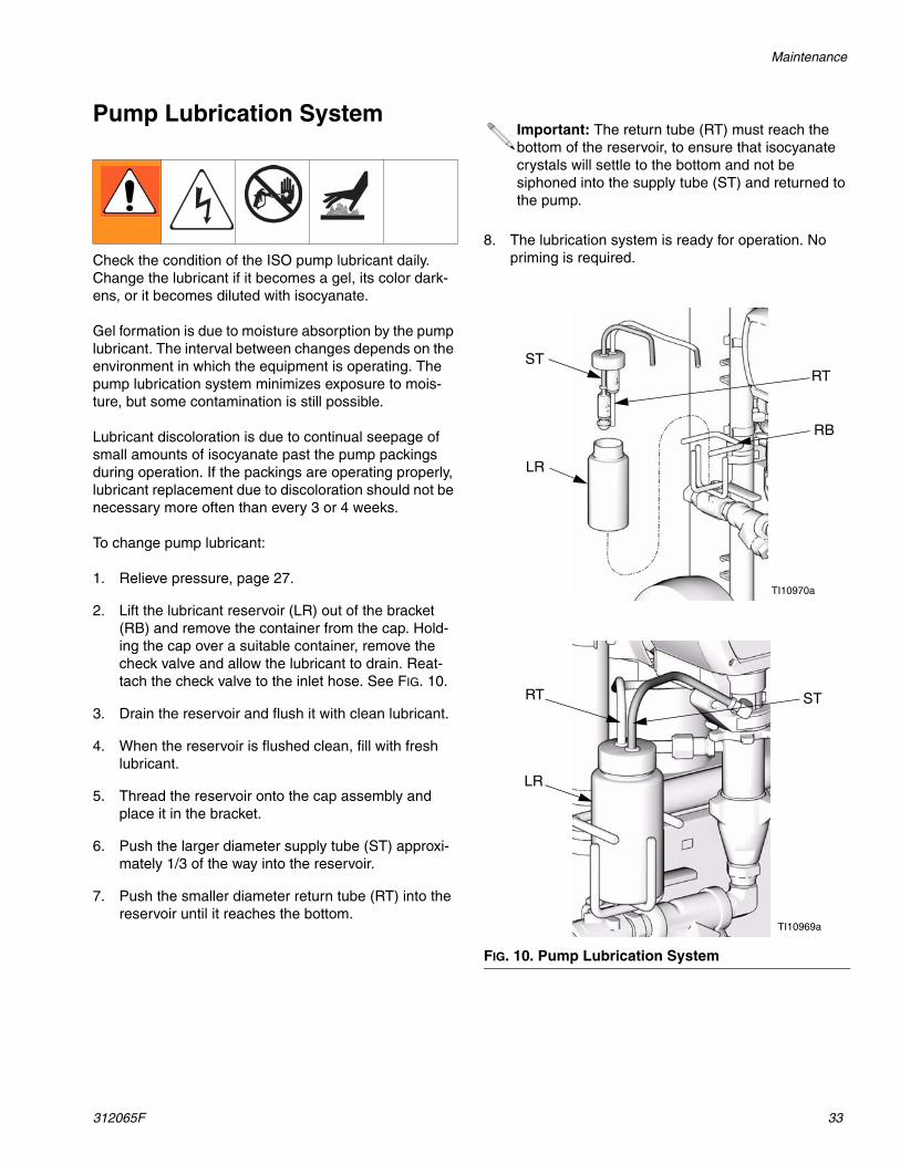
Pump Lubrication System
Check the condition of the ISO pump lubricant daily. Change the lubricant if it becomes a gel, its color dark-ens, or it becomes diluted with isocyanate.
Gel formation is due to moisture absorption by the pump lubricant. The interval between changes depends on the environment in which the equipment is operating. The pump lubrication system minimizes exposure to mois-ture, but some contamination is still possible.
Lubricant discoloration is due to continual seepage of small amounts of isocyanate past the pump packings during operation. If the packings are operating properly, lubricant replacement due to discoloration should not be necessary more often than every 3 or 4 weeks.
To change pump lubricant:
1. Relieve pressure, page 27.
2. Lift the lubricant reservoir (LR) out of the bracket (RB) and remove the container from the cap. Hold-ing the cap over a suitable container, remove the check valve and allow the lubricant to drain. Reat-tach the check valve to the inlet hose. See FIG. 10.
3. Drain the reservoir and flush it with clean lubricant.
4. When the reservoir is flushed clean, fill with fresh lubricant.
5. Thread the reservoir onto the cap assembly and place it in the bracket.
6. Push the larger diameter supply tube (ST) approxi-mately 1/3 of the way into the reservoir.
7. Push the smaller diameter return tube (RT) into the reservoir until it reaches the bottom.
8. The lubrication system is ready for operation. No priming is required.
Important: The return tube (RT) must reach the bottom of the reservoir, to ensure that isocyanate crystals will settle to the bottom and not be siphoned into the supply tube (ST) and returned to the pump.
FIG. 10. Pump Lubrication System
LR
RTST
RB
TI10970a
TI10969a
LR
STRT
Flushing
34 312065F
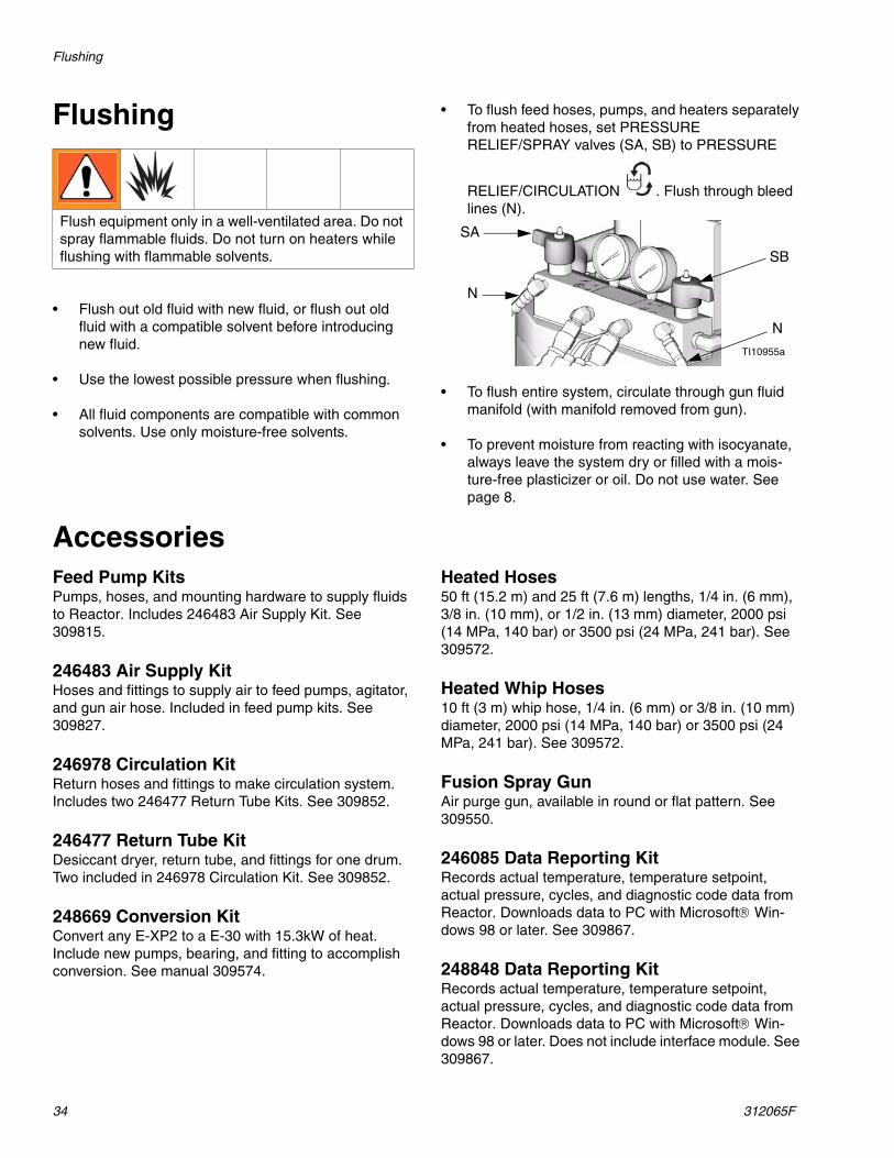
Flushing
• Flush out old fluid with new fluid, or flush out old fluid with a compatible solvent before introducing new fluid.
• Use the lowest possible pressure when flushing.
• All fluid components are compatible with common solvents. Use only moisture-free solvents.
• To flush feed hoses, pumps, and heaters separately from heated hoses, set PRESSURE RELIEF/SPRAY valves (SA, SB) to PRESSURE
RELIEF/CIRCULATION . Flush through bleed lines (N).
• To flush entire system, circulate through gun fluid manifold (with manifold removed from gun).
• To prevent moisture from reacting with isocyanate, always leave the system dry or filled with a mois-ture-free plasticizer or oil. Do not use water. See page 8.
AccessoriesFeed Pump KitsPumps, hoses, and mounting hardware to supply fluids to Reactor. Includes 246483 Air Supply Kit. See 309815.
246483 Air Supply KitHoses and fittings to supply air to feed pumps, agitator, and gun air hose. Included in feed pump kits. See 309827.
246978 Circulation KitReturn hoses and fittings to make circulation system. Includes two 246477 Return Tube Kits. See 309852.
246477 Return Tube KitDesiccant dryer, return tube, and fittings for one drum. Two included in 246978 Circulation Kit. See 309852.
248669 Conversion KitConvert any E-XP2 to a E-30 with 15.3kW of heat. Include new pumps, bearing, and fitting to accomplish conversion. See manual 309574.
Heated Hoses50 ft (15.2 m) and 25 ft (7.6 m) lengths, 1/4 in. (6 mm), 3/8 in. (10 mm), or 1/2 in. (13 mm) diameter, 2000 psi (14 MPa, 140 bar) or 3500 psi (24 MPa, 241 bar). See 309572.
Heated Whip Hoses10 ft (3 m) whip hose, 1/4 in. (6 mm) or 3/8 in. (10 mm) diameter, 2000 psi (14 MPa, 140 bar) or 3500 psi (24 MPa, 241 bar). See 309572.
Fusion Spray GunAir purge gun, available in round or flat pattern. See 309550.
246085 Data Reporting KitRecords actual temperature, temperature setpoint, actual pressure, cycles, and diagnostic code data from Reactor. Downloads data to PC with Microsoft® Win-dows 98 or later. See 309867.
248848 Data Reporting KitRecords actual temperature, temperature setpoint, actual pressure, cycles, and diagnostic code data from Reactor. Downloads data to PC with Microsoft® Win-dows 98 or later. Does not include interface module. See 309867.
Flush equipment only in a well-ventilated area. Do not spray flammable fluids. Do not turn on heaters while flushing with flammable solvents.
TI10955a
SA
SB
N
N
Accessories
312065F 35
Dimensions
36 312065F
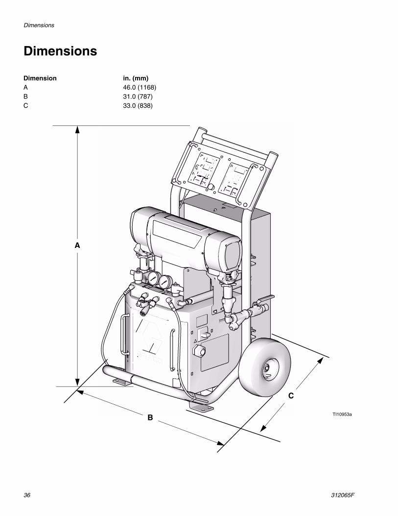
Dimensions
Dimension in. (mm)A 46.0 (1168)B 31.0 (787)C 33.0 (838)
TI10953aB
A
C
Technical Data
312065F 37
Technical Data
All other brand names or marks are used for identification purposes and are trademarks of their respective owners.
Category DataMaximum Fluid Working Pressure Models E-20 and E-30: 2000 psi (14 MPa, 140 bar)
Model E-XP1: 2500 psi (17.2 MPa, 172 bar)
Model E-XP2: 3500 psi (24.1 MPa, 241 bar)Maximum Fluid Temperature 190°F (88°C)Maximum Output Model E-20: 20 lb/min (9 kg/min)
Model E-30: 30 lb/min (13.5 kg/min)
Model E-XP1: 1 gpm (3.8 liter/min)
Model E-XP2: 2 gpm (7.6 liter/min)Output per Cycle (A and B) Model E-20 and E-XP1: 0.0104 gal. (0.0395 liter)
Model E-30: 0272 gal. (0.1034 liter)
Model E-XP2: 0.0203 gal. (.0771 liter)Line Voltage Requirement Parts 259024, 259025, 259026, 259028, 259057: 195-264 Vac, 50/60 Hz
Parts 259029, 259030, 259031, 259032, 259059: 338-457 Vac, 50/60 Hz
Parts 2590330, 259034, 259035, 259036, 259058: 195-264 Vac, 50/60 HzAmperage Requirement See Table 1, page 16.Heater Power Model E-20: 6000 Watts
Model E-30 and E-XP1: 10200 Watts
Models E-XP2 and E-30 with 15.3kW of heat: 15300 WattsSound Power, per ISO 9614-2 Model E-20: 80 dB(A) at 2000 psi (14 MPa, 140 bar), 0.5 gpm (1.9 lpm)
Model E-30: 93.5 dB(A) at 1000 psi (7 MPa, 70 bar), 3.0 gpm (11.4 lpm)
Model E-XP1: 80 dB(A) at 2000 psi (14 MPa, 140 bar), 0.5 gpm (1.9 lpm)
Model E-XP2: 83.5 dB(A) at 3000 psi (21 MPa, 210 bar), 1.0 gpm (3.8 lpm)Sound Pressure, 1 m from equipment Model E-20: 70.2 dB(A) at 2000 psi (14 MPa, 140 bar), 0.5 gpm (1.9 lpm)
Model E-30: 83.6 dB(A) at 1000 psi (7 MPa, 70 bar), 3.0 gpm (11.4 lpm)
Model E-XP1: 70.2 dB(A) at 2000 psi (14 MPa, 140 bar), 0.5 gpm (1.9 lpm)
Model E-XP2: 73.6 dB(A) at 3000 psi (21 MPa, 210 bar), 1.0 gpm (3.8 lpm)Fluid Inlets 3/4 npt(f), with 3/4 npsm(f) unionFluid Outlets Component A (ISO): #8 (1/2 in.) JIC, with #5 (5/16 in.) JIC adapter
Component B (RES): #10 (5/8 in.) JIC, with #6 (3/8 in.) JIC adapterFluid Circulation Ports 1/4 npsm(m), with plastic tubing; 250 psi (1.75 MPa, 17.5 bar) maximumWeight Model E-20 and E-XP1: 342 lb (155 kg)
Model E-30: 400 lb (181kg)
Models E-XP2 and E-30 with 15.3kW of heat: 438 lb (198 kg)Wetted Parts Aluminum, stainless steel, zinc plated, carbon steel, brass, carbide, chrome,
All written and visual data contained in this document reflects the latest product information available at the time of publication. Graco reserves the right to make changes at any time without notice.
This manual contains English. MM 312065
Graco Headquarters: MinneapolisInternational Offices: Belgium, China, Japan, Korea
GRACO INC. P.O. BOX 1441 MINNEAPOLIS, MN 55440-1441Copyright 2007, Graco Inc. is registered to ISO 9001
www.graco.comRevised 03/2009
Graco Standard WarrantyGraco warrants all equipment referenced in this document which is manufactured by Graco and bearing its name to be free from defects in material and workmanship on the date of sale to the original purchaser for use. With the exception of any special, extended, or limited warranty published by Graco, Graco will, for a period of twelve months from the date of sale, repair or replace any part of the equipment determined by Graco to be defective. This warranty applies only when the equipment is installed, operated and maintained in accordance with Graco’s written recommendations.
This warranty does not cover, and Graco shall not be liable for general wear and tear, or any malfunction, damage or wear caused by faulty installation, misapplication, abrasion, corrosion, inadequate or improper maintenance, negligence, accident, tampering, or substitution of non-Graco component parts. Nor shall Graco be liable for malfunction, damage or wear caused by the incompatibility of Graco equipment with structures, accessories, equipment or materials not supplied by Graco, or the improper design, manufacture, installation, operation or maintenance of structures, accessories, equipment or materials not supplied by Graco.
This warranty is conditioned upon the prepaid return of the equipment claimed to be defective to an authorized Graco distributor for verification of the claimed defect. If the claimed defect is verified, Graco will repair or replace free of charge any defective parts. The equipment will be returned to the original purchaser transportation prepaid. If inspection of the equipment does not disclose any defect in material or workmanship, repairs will be made at a reasonable charge, which charges may include the costs of parts, labor, and transportation.
THIS WARRANTY IS EXCLUSIVE, AND IS IN LIEU OF ANY OTHER WARRANTIES, EXPRESS OR IMPLIED, INCLUDING BUT NOT LIMITED TO WARRANTY OF MERCHANTABILITY OR WARRANTY OF FITNESS FOR A PARTICULAR PURPOSE.
Graco’s sole obligation and buyer’s sole remedy for any breach of warranty shall be as set forth above. The buyer agrees that no other remedy (including, but not limited to, incidental or consequential damages for lost profits, lost sales, injury to person or property, or any other incidental or consequential loss) shall be available. Any action for breach of warranty must be brought within two (2) years of the date of sale.
GRACO MAKES NO WARRANTY, AND DISCLAIMS ALL IMPLIED WARRANTIES OF MERCHANTABILITY AND FITNESS FOR A PARTICULAR PURPOSE, IN CONNECTION WITH ACCESSORIES, EQUIPMENT, MATERIALS OR COMPONENTS SOLD BUT NOT MANUFACTURED BY GRACO. These items sold, but not manufactured by Graco (such as electric motors, switches, hose, etc.), are subject to the warranty, if any, of their manufacturer. Graco will provide purchaser with reasonable assistance in making any claim for breach of these warranties.
In no event will Graco be liable for indirect, incidental, special or consequential damages resulting from Graco supplying equipment hereunder, or the furnishing, performance, or use of any products or other goods sold hereto, whether due to a breach of contract, breach of warranty, the negligence of Graco, or otherwise.
FOR GRACO CANADA CUSTOMERSThe Parties acknowledge that they have required that the present document, as well as all documents, notices and legal proceedings entered into, given or instituted pursuant hereto or relating directly or indirectly hereto, be drawn up in English. Les parties reconnaissent avoir convenu que la rédaction du présente document sera en Anglais, ainsi que tous documents, avis et procédures judiciaires exécutés, donnés ou intentés, à la suite de ou en rapport, directement ou indirectement, avec les procédures concernées.
Graco Information TO PLACE AN ORDER, contact your Graco distributor or call to identify the nearest distributor.Phone: 612-623-6921 or Toll Free: 1-800-328-0211, Fax: 612-378-3505