Congratulations on the purchase of your new spreader from Roto-Mix. With proper operation and preventative maintenance it will last for years.
This SAFETY ALERT SYMBOL indicates
important safety messages in the manual. When you see this symbol, be alert to the possibility of PERSONAL INJURY and carefully read the message that follows.
NEVER OPERATE WITHOUT
ALL COVERS, SHIELDS AND GUARDS IN PLACE. KEEP HANDS, FEET AND CLOTHING AWAY FROM MOVING PARTS. Some covers and guards have been removed for illustra-tive/photographic purposes only in this manual. How-ever, equipment should never be operated in this condi-tion. Keep all shields in place. If shield removal becomes necessary for repairs, replace the shield prior to use.
The Guarantee appears in the front of this book along with the Registration and Inspection Certificate. For information on ordering repair parts, refer to the Re-pair Parts section at the back of this book. The serial number plate is located on the drivers side lower front of the main frame. This number should be recorded on the Registration and Inspection Certificate for your reference and for proper identification of your spreader by Roto-Mix. You are urged to study this manual and follow the in-structions carefully. Your efforts will be repaid in better operation and service as well as a savings in time and repair expense. Failure to read and understand the ma-chine or the system could lead to serious injury. If you do not understand the instructions in this manual contact either your dealer or Roto-Mix at Dodge City, Kansas 67801. This supersedes all previous published instructions.
Page 2
Warranty Statement WS-0716
ROTO-MIX LLC warrants to the original purchaser all products manufactured by it to be free from defects in material and workmanship under normal use and service. ROTO-MIX’s obligation under this warranty is limited to repairing or replacing, as the company may elect, free of charge and without charge for installation, at the place of business of a dealer or distributor authorized to handle the equipment covered by this warranty or at a ROTO-MIX facility, any parts that prove, in the company’s judgment, to be defective in material or workmanship within one (1) year after delivery to the original purchaser, and still owned by the original purchaser. This warranty shall in no way make ROTO-MIX liable to anyone for personal injuries or damages, loss of time, or expense of any kind either direct or indirect resulting from part failure or defect. This warranty is subject to acts of God, fire and existing conditions of supply and demand, or production, or ability or inability to deliver, or for any other valid reason beyond the reasonable control of ROTO-MIX, to obtain materials, manufactured replacement parts, or make delivery thereof. No distributor, dealer, agent, or ROTO-MIX employee (other than the CEO or President in writing) is authorized to extend any other or further express or implied warranty or incur any additional obligation on ROTO-MIX’s behalf in connection with the sale of this product.
If ROTO─MIX, or its duly authorized representative, shall find that such returned part or parts are defective and such defects, or defect, are included in and covered by said warranty, then such defective part or parts shall promptly be replaced without charge to the purchaser, F.O.B. the ROTO─MIX plant. Product Registration - It is a condition of this warranty that the original purchaser must fill out the warranty card furnished by ROTO-MIX and that it be returned to ROTO-MIX within 10 days of purchase and be recorded in ROTO-MIX’s owner file for this warranty to be valid. In the event an owner’s card is not on file at the ROTO-MIX office, the warranty period will extend only from date equipment was picked up or shipped from the ROTO-MIX plant. Maintenance - It is the customer’s responsibility to maintain their equipment in accordance with the instructions provided in the Operator’s Manual. ROTO-MIX recommends that you keep records and receipts; you may be asked to prove that maintenance instructions have been followed. Operation – It is the customer’s responsibility to operate the equipment only for the purpose for which it was designed and in accordance with all safety and operational recommendations contained in the Operators Manual. If a defect in materials or workmanship occurs, it is the customer’s responsibility to cease operating the equipment until authorized repairs are made. Damage, which occurs from continued operation, may not be covered by this warranty. What this Warranty Covers This warranty covers failures caused by defects in materials or workmanship only. This Warranty does not cover failures caused by:
This Warranty does not cover replacement of Wear or Maintenance Items including, but not limited to.
This Warranty does not cover: - Pickup and delivery of the equipment
- Service Calls or Travel Time to and from sites
- Rental of replacement equipment during repair period
- Products that have been declared a total loss and subsequently salvaged
- Overtime labor charges
- ROTO-MIX is not responsible and will not be liable for damage caused to persons or property, commercial loss, loss of time or production, loss of use by reason of the installation or use of ROTO-MIX products or their mechanical failure.
Right to Make Changes ROTO-MIX reserves the right to make any changes to a ROTO-MIX product at any time without incurring any obligation with respect to any product previously ordered, sold or shipped, with or without notice. Parts Warranty ROTO-MIX warranties replacement parts against defects in materials or workmanship for a period of 90 days or the remainder of the product warranty, whichever is longer. Remedy for defective replacement parts for units that are beyond the original product warranty, will be limited to replacement of the failed part. Failures that are due to damage, improper installation, lack of maintenance or improper operation will not be covered. ROTO-MIX 2205 East Wyatt Earp Blvd., Dodge City, KS 67801 (620) 225-1142 Fax: (620) 225-6370
Indicates an imminently hazardoussituation that, if not avoided, will result in death or seriousinjury.
situation that, if not avoided may result in minor ormoderate injury.
Indicates a potentially hazardous
Indicates a potentially hazardoussituation that, if not avoided could result in death orserious injury, and includes hazards that are exposedwhen guards are removed.
SAFETY - SPREADER
Page 5SAFETY DECAL PAGE.
READ ALL SIGNS ON THE MACHINE AND IN THIS MANUAL. REPLACEANY LOST OR DAMAGED SIGN BY ORDERING THE PART NUMBERS SHOWN ON THE
A brief definition of signal words that may be used in this manual:
Page 6
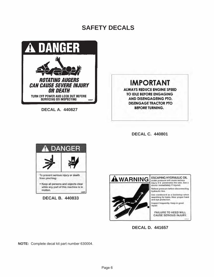
SAFETY DECALS
NOTE: Complete decal kit part number 630004.
DECAL A. 440827
DECAL C. 440801
DECAL B. 440833
DECAL D. 441657
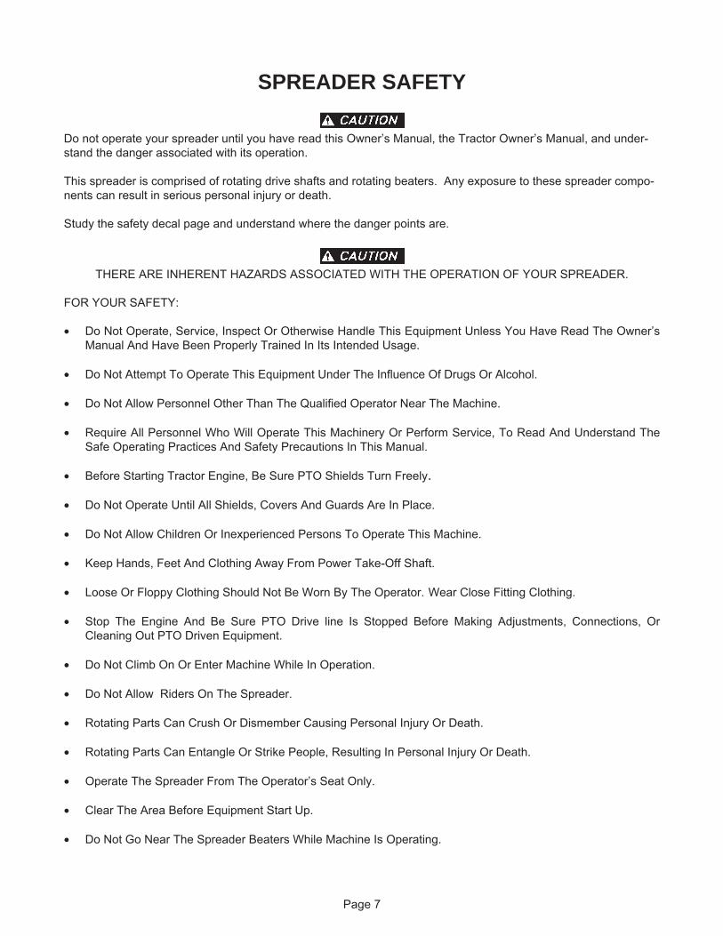
SPREADER SAFETY
Do not operate your spreader until you have read this Owner’s Manual, the Tractor Owner’s Manual, and under-stand the danger associated with its operation.
This spreader is comprised of rotating drive shafts and rotating beaters. Any exposure to these spreader compo-nents can result in serious personal injury or death.
Study the safety decal page and understand where the danger points are.
THERE ARE INHERENT HAZARDS ASSOCIATED WITH THE OPERATION OF YOUR SPREADER.
FOR YOUR SAFETY:
• Do Not Operate, Service, Inspect Or Otherwise Handle This Equipment Unless You Have Read The Owner’sManual And Have Been Properly Trained In Its Intended Usage.
• Do Not Attempt To Operate This Equipment Under The Influence Of Drugs Or Alcohol.
• Do Not Allow Personnel Other Than The Qualified Operator Near The Machine.
• Require All Personnel Who Will Operate This Machinery Or Perform Service, To Read And Understand TheSafe Operating Practices And Safety Precautions In This Manual.
• Before Starting Tractor Engine, Be Sure PTO Shields Turn Freely.
• Do Not Operate Until All Shields, Covers And Guards Are In Place.
• Do Not Allow Children Or Inexperienced Persons To Operate This Machine.
• Keep Hands, Feet And Clothing Away From Power Take-Off Shaft.
• Loose Or Floppy Clothing Should Not Be Worn By The Operator. Wear Close Fitting Clothing.
• Stop The Engine And Be Sure PTO Drive line Is Stopped Before Making Adjustments, Connections, OrCleaning Out PTO Driven Equipment.
• Do Not Climb On Or Enter Machine While In Operation.
• Do Not Allow Riders On The Spreader.
• Rotating Parts Can Crush Or Dismember Causing Personal Injury Or Death.
• Rotating Parts Can Entangle Or Strike People, Resulting In Personal Injury Or Death.
• Operate The Spreader From The Operator’s Seat Only.
• Clear The Area Before Equipment Start Up.
• Do Not Go Near The Spreader Beaters While Machine Is Operating.
Page 7
• Stay Clear Of Rotating Drive lines
• Entanglement In Rotating Drive line Can Cause Serious Injury Or Death.
• Make Sure Rotating Shields Turn Freely.
• Do Not Exceed Load Capacity Of The Spreader (See Specifications).
• Always Use A Tractor Large Enough To Provide Sufficient Braking Assistance When Towing A LoadedSpreader.
• Do Not Load The Spreader Unless It Is Hitched To The Tractor.
• Do Not Unhitch A Loaded Spreader From The Tractor Leaving It Supported By Only The Jack.
• Reduce Speed When Turning Or Traveling On Rough Terrain. Avoid Traveling Over Loose Fill, Rocks,Ditches Or Holes.
• Do Not Operate On Steep Slopes As Overturn May Result. Operate Up And Down (Not Across) IntermediateSlopes. Avoid Sudden Starts And Stops. Pick The Most Level Possible Route When Transporting AcrossFields. Avoid The Edges Of Ditches Or Gullies And Steep Hillsides.
• Use Caution When Traveling Over Uneven Terrain And When Approaching Stops.
• Keep Transmission In Gear When Traveling Downhill.
• Keep Tractor Master Shield And Drive line Shields In Place At All Times.
• Avoid Overhead Wires Or Other Obstacles. Contact With Overhead Lines Could Cause Serious Injury OrDeath.
• Highway Travel Is Not To Exceed 20 MPH. The Tires Supplied Are For Farm Use Only And Are Not DesignedFor Use Above This Speed.
• Use Adequate Safety Chains When Towing The Spreader.
• The Use Of A Slow Moving Vehicle Sign Is Required On All Public Roads. Obey All Applicable HighwaySafety Laws And Rules.
• As A Precaution, Always Recheck The Hardware On Spreader Following Every 100 Hours Of Operation. Cor-rect All Problems. Follow The Maintenance Safety Procedures.
FAILURE TO HEED MAY RESULT IN SERIOUS PERSONAL INJURY OR DEATH.
Page 8
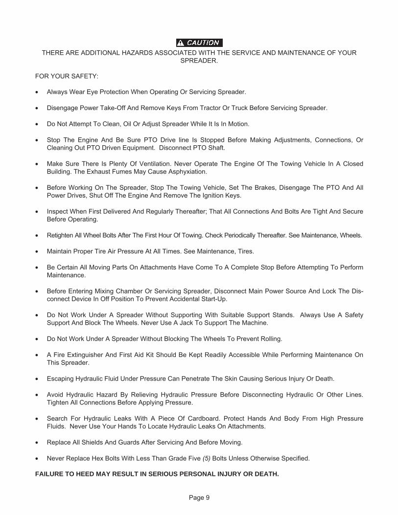
THERE ARE ADDITIONAL HAZARDS ASSOCIATED WITH THE SERVICE AND MAINTENANCE OF YOURSPREADER.
FOR YOUR SAFETY:
• Always Wear Eye Protection When Operating Or Servicing Spreader.
• Disengage Power Take-Off And Remove Keys From Tractor Or Truck Before Servicing Spreader.
• Do Not Attempt To Clean, Oil Or Adjust Spreader While It Is In Motion.
• Stop The Engine And Be Sure PTO Drive line Is Stopped Before Making Adjustments, Connections, OrCleaning Out PTO Driven Equipment. Disconnect PTO Shaft.
• Make Sure There Is Plenty Of Ventilation. Never Operate The Engine Of The Towing Vehicle In A ClosedBuilding. The Exhaust Fumes May Cause Asphyxiation.
• Before Working On The Spreader, Stop The Towing Vehicle, Set The Brakes, Disengage The PTO And AllPower Drives, Shut Off The Engine And Remove The Ignition Keys.
• Inspect When First Delivered And Regularly Thereafter; That All Connections And Bolts Are Tight And SecureBefore Operating.
• Retighten All Wheel Bolts After The First Hour Of Towing. Check Periodically Thereafter. See Maintenance, Wheels.
• Maintain Proper Tire Air Pressure At All Times. See Maintenance, Tires.
• Be Certain All Moving Parts On Attachments Have Come To A Complete Stop Before Attempting To PerformMaintenance.
• Before Entering Mixing Chamber Or Servicing Spreader, Disconnect Main Power Source And Lock The Dis-connect Device In Off Position To Prevent Accidental Start-Up.
• Do Not Work Under A Spreader Without Supporting With Suitable Support Stands. Always Use A SafetySupport And Block The Wheels. Never Use A Jack To Support The Machine.
• Do Not Work Under A Spreader Without Blocking The Wheels To Prevent Rolling.
• A Fire Extinguisher And First Aid Kit Should Be Kept Readily Accessible While Performing Maintenance OnThis Spreader.
• Escaping Hydraulic Fluid Under Pressure Can Penetrate The Skin Causing Serious Injury Or Death.
• Avoid Hydraulic Hazard By Relieving Hydraulic Pressure Before Disconnecting Hydraulic Or Other Lines.Tighten All Connections Before Applying Pressure.
• Search For Hydraulic Leaks With A Piece Of Cardboard. Protect Hands And Body From High PressureFluids. Never Use Your Hands To Locate Hydraulic Leaks On Attachments.
• Replace All Shields And Guards After Servicing And Before Moving.
• Never Replace Hex Bolts With Less Than Grade Five (5) Bolts Unless Otherwise Specified.
FAILURE TO HEED MAY RESULT IN SERIOUS PERSONAL INJURY OR DEATH.
Page 9
REMEMBER:Your best assurance against accidents is a careful and responsible operator. If there is any portion of this manualor function you do not understand, contact your dealer or the ROTO-MIX plant.
Safety Decal Care1. Keep safety decals and signs clean and legible at all times.2. Replace safety decals and signs that are missing or have become illegible.3. Replaced parts that displayed a safety sign should also display the current sign.4. Safety decals or signs are available from your dealer or the ROTO-MIX manufacturing plant.5. How to Install Safety Decals:
A. Be sure that the installation area is clean and dry.B. Decide on the exact position before you remove the backing paper.C. Remove the smallest portion of the split backing paper.D. Align the decal over the specified area and carefully press the small portion with the exposed sticky
backing in place.E. Slowly peel back the remaining paper and carefully smooth the remaining portion of the decal in place.F. Small air pockets can be pierced with a pin and smoothed out using the piece of decal backing paper.
FAILURE TO HEED MAY RESULT IN SERIOUS PERSONAL INJURY OR DEATH.
Page 10
122 3/4" (MIN.)144-1/2" (MAX.)
532-16 & 672-20 TRAILER DIMENSIONAL DATA
SPECIFICATIONS
Page 11
MIN. & MAX. DIMENSIONS REPRESENT THE DIFFERENCE IN THE AVAILABLE TIRE SIZED.
31 1/4"
(MIN.)124" (MAX.)
532-16 (216")672-20 (264")
532-16 (339")
121"
672-20 (318")532-16 (270")
(MIN.)34 1/4" (MAX.)
672-20 (387")
104" (MIN.)107" (MAX.)
124" (MAX.)121" (MIN.)
89"
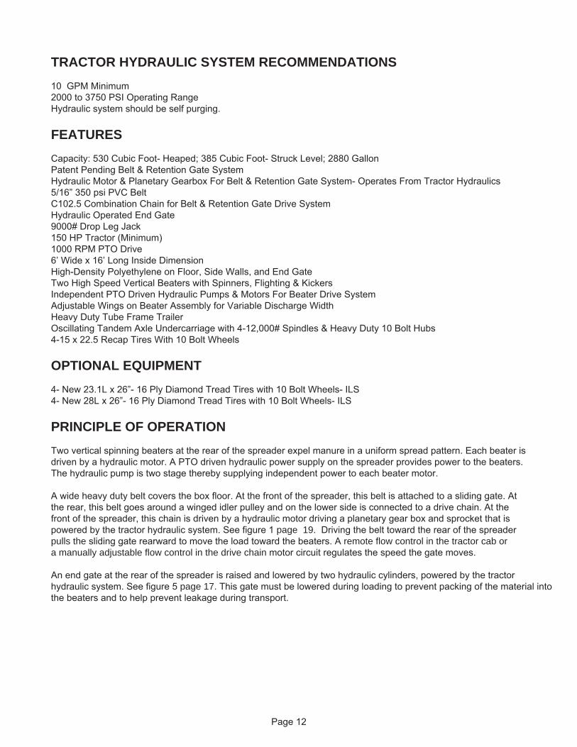
TRACTOR HYDRAULIC SYSTEM RECOMMENDATIONS
10 GPM Minimum2000 to 3750 PSI Operating RangeHydraulic system should be self purging.
FEATURES
Capacity: 530 Cubic Foot- Heaped; 385 Cubic Foot- Struck Level; 2880 GallonPatent Pending Belt & Retention Gate SystemHydraulic Motor & Planetary Gearbox For Belt & Retention Gate System- Operates From Tractor Hydraulics5/16” 350 psi PVC BeltC102.5 Combination Chain for Belt & Retention Gate Drive SystemHydraulic Operated End Gate9000# Drop Leg Jack150 HP Tractor (Minimum)1000 RPM PTO Drive6’ Wide x 16’ Long Inside DimensionHigh-Density Polyethylene on Floor, Side Walls, and End GateTwo High Speed Vertical Beaters with Spinners, Flighting & KickersIndependent PTO Driven Hydraulic Pumps & Motors For Beater Drive SystemAdjustable Wings on Beater Assembly for Variable Discharge WidthHeavy Duty Tube Frame TrailerOscillating Tandem Axle Undercarriage with 4-12,000# Spindles & Heavy Duty 10 Bolt Hubs4-15 x 22.5 Recap Tires With 10 Bolt Wheels
OPTIONAL EQUIPMENT
4- New 23.1L x 26”- 16 Ply Diamond Tread Tires with 10 Bolt Wheels- ILS4- New 28L x 26”- 16 Ply Diamond Tread Tires with 10 Bolt Wheels- ILS
PRINCIPLE OF OPERATION
Two vertical spinning beaters at the rear of the spreader expel manure in a uniform spread pattern. Each beater isdriven by a hydraulic motor. A PTO driven hydraulic power supply on the spreader provides power to the beaters.The hydraulic pump is two stage thereby supplying independent power to each beater motor.
A wide heavy duty belt covers the box floor. At the front of the spreader, this belt is attached to a sliding gate. Atthe rear, this belt goes around a winged idler pulley and on the lower side is connected to a drive chain. At thefront of the spreader, this chain is driven by a hydraulic motor driving a planetary gear box and sprocket that ispowered by the tractor hydraulic system. See figure 1 page 19. Driving the belt toward the rear of the spreaderpulls the sliding gate rearward to move the load toward the beaters. A remote flow control in the tractor cab ora manually adjustable flow control in the drive chain motor circuit regulates the speed the gate moves.
An end gate at the rear of the spreader is raised and lowered by two hydraulic cylinders, powered by the tractorhydraulic system. See figure 5 page 17. This gate must be lowered during loading to prevent packing of the material intothe beaters and to help prevent leakage during transport.
Page 12
Page 13
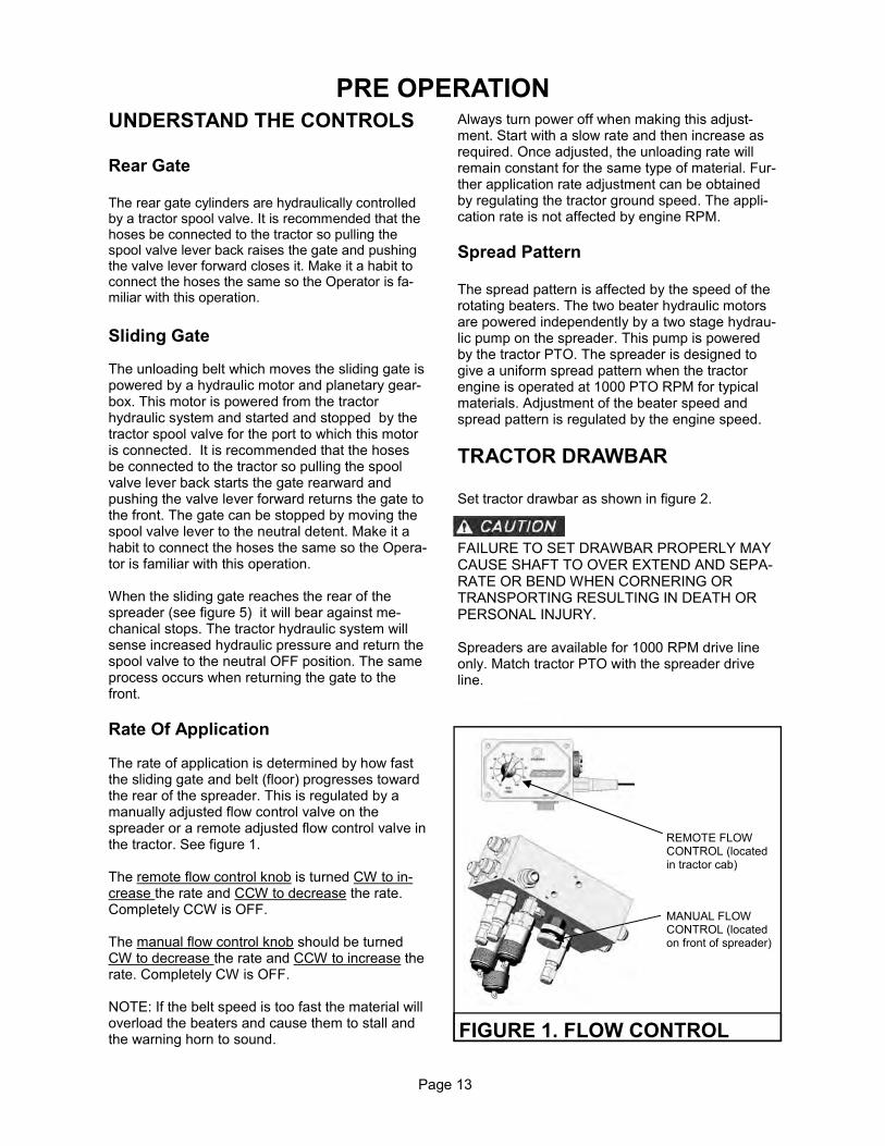
PRE OPERATION UNDERSTAND THE CONTROLS Rear Gate The rear gate cylinders are hydraulically controlled by a tractor spool valve. It is recommended that the hoses be connected to the tractor so pulling the spool valve lever back raises the gate and pushing the valve lever forward closes it. Make it a habit to connect the hoses the same so the Operator is fa-miliar with this operation. Sliding Gate The unloading belt which moves the sliding gate is powered by a hydraulic motor and planetary gear-box. This motor is powered from the tractor hydraulic system and started and stopped by the tractor spool valve for the port to which this motor is connected. It is recommended that the hoses be connected to the tractor so pulling the spool valve lever back starts the gate rearward and pushing the valve lever forward returns the gate to the front. The gate can be stopped by moving the spool valve lever to the neutral detent. Make it a habit to connect the hoses the same so the Opera-tor is familiar with this operation. When the sliding gate reaches the rear of the spreader (see figure 5) it will bear against me-chanical stops. The tractor hydraulic system will sense increased hydraulic pressure and return the spool valve to the neutral OFF position. The same process occurs when returning the gate to the front. Rate Of Application The rate of application is determined by how fast the sliding gate and belt (floor) progresses toward the rear of the spreader. This is regulated by a manually adjusted flow control valve on the spreader or a remote adjusted flow control valve in the tractor. See figure 1. The remote flow control knob is turned CW to in-crease the rate and CCW to decrease the rate. Completely CCW is OFF. The manual flow control knob should be turned CW to decrease the rate and CCW to increase the rate. Completely CW is OFF. NOTE: If the belt speed is too fast the material will overload the beaters and cause them to stall and the warning horn to sound.
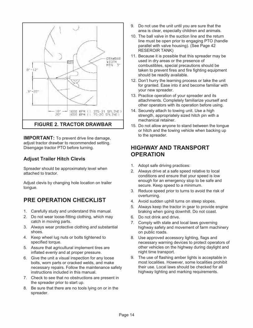
Always turn power off when making this adjust-ment. Start with a slow rate and then increase as required. Once adjusted, the unloading rate will remain constant for the same type of material. Fur-ther application rate adjustment can be obtained by regulating the tractor ground speed. The appli-cation rate is not affected by engine RPM. Spread Pattern The spread pattern is affected by the speed of the rotating beaters. The two beater hydraulic motors are powered independently by a two stage hydrau-lic pump on the spreader. This pump is powered by the tractor PTO. The spreader is designed to give a uniform spread pattern when the tractor engine is operated at 1000 PTO RPM for typical materials. Adjustment of the beater speed and spread pattern is regulated by the engine speed. TRACTOR DRAWBAR Set tractor drawbar as shown in figure 2.
FAILURE TO SET DRAWBAR PROPERLY MAY CAUSE SHAFT TO OVER EXTEND AND SEPA-RATE OR BEND WHEN CORNERING OR TRANSPORTING RESULTING IN DEATH OR PERSONAL INJURY. Spreaders are available for 1000 RPM drive line only. Match tractor PTO with the spreader drive line.
FIGURE 1. FLOW CONTROL
REMOTE FLOW CONTROL (located in tractor cab)
MANUAL FLOW CONTROL (located on front of spreader)
Page 14
IMPORTANT: To prevent drive line damage, adjust tractor drawbar to recommended setting. Disengage tractor PTO before turning. Adjust Trailer Hitch Clevis Spreader should be approximately level when attached to tractor. Adjust clevis by changing hole location on trailer tongue. PRE OPERATION CHECKLIST 1. Carefully study and understand this manual. 2. Do not wear loose-fitting clothing, which may
catch in moving parts. 3. Always wear protective clothing and substantial
shoes. 4. Keep wheel lug nuts or bolts tightened to
specified torque. 5. Assure that agricultural implement tires are
inflated evenly and at proper pressure. 6. Give the unit a visual inspection for any loose
bolts, worn parts or cracked welds, and make necessary repairs. Follow the maintenance safety instructions included in this manual.
7. Check to see that no obstructions are present in the spreader prior to start up.
8. Be sure that there are no tools lying on or in the spreader.
9. Do not use the unit until you are sure that the area is clear, especially children and animals.
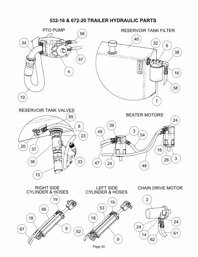
10. The ball valve in the suction line and the return line must be open prior to engaging PTO (handle parallel with valve housing). (See Page 42 RESEROIR TANK)
11. Because it is possible that this spreader may be used in dry areas or the presence of combustibles, special precautions should be taken to prevent fires and fire fighting equipment should be readily available.
12. Don’t hurry the learning process or take the unit for granted. Ease into it and become familiar with your new spreader.
13. Practice operation of your spreader and its attachments. Completely familiarize yourself and other operators with its operation before using.
14. Securely attach to towing unit. Use a high strength, appropriately sized hitch pin with a mechanical retainer.
15. Do not allow anyone to stand between the tongue or hitch and the towing vehicle when backing up to the spreader.
HIGHWAY AND TRANSPORT OPERATION 1. Adopt safe driving practices: 2. Always drive at a safe speed relative to local
conditions and ensure that your speed is low enough for an emergency stop to be safe and secure. Keep speed to a minimum.
3. Reduce speed prior to turns to avoid the risk of overturning.
4. Avoid sudden uphill turns on steep slopes. 5. Always keep the tractor in gear to provide engine
braking when going downhill. Do not coast. 6. Do not drink and drive. 7. Comply with state and local laws governing
highway safety and movement of farm machinery on public roads.
8. Use approved accessory lighting, flags and necessary warning devices to protect operators of other vehicles on the highway during daylight and night time transport.
9. The use of flashing amber lights is acceptable in most localities. However, some localities prohibit their use. Local laws should be checked for all highway lighting and marking requirements.
FIGURE 2. TRACTOR DRAWBAR
10. The spreader does not have brakes. Towing thespreader must be done safely. The ASAE(American Society of Agricultural Engineers)specifies that the towing vehicle should weigh atleast 2/3 as much as the loaded implement to bereasonably safe towing at speeds up to 20 mph.This (20 mph) is also the maximumrecommended towing speed for the spreader.
11. When driving the tractor and spreader on theroad or highway at night or during the day, useflashing amber warning lights and a slow movingvehicle (SMV) identification emblem.
12. Be sure the slow moving vehicle sign is installedon the rear of the spreader for transporting onroadways.
13. Plan your route to avoid heavy traffic.14. Be a safe courteous driver. Always yield to
oncoming traffic in all situations, including narrowbridges, intersections, etc.
15. Be observant of bridge loading ratings. Do notcross bridges rated lower than the gross weightat which you are operating.
16. Watch for obstructions overhead and to the sidewhile transporting.
17. Make allowances for increased length and weightof the spreader when making turns, stopping theunit, etc.
18. Install safety chains as illustrated on figure 3.This is a requirement for travel on publicroadways. They are installed to retain theconnection between tractor (or other towingvehicle) and spreader whenever traveling onpublic roads.
Lighting and Marking
It is the responsibility of the customer to know the light-ing and marking requirements of the local highway au-thorities and to install and maintain the equipment toprovide compliance with the regulations. Add extralights when transporting at night or during periods oflimited visibility.
Page 15
FIGURE 3. SAFETY CHAIN INSTALLATION
PTO SHAFT IN STOREDPOSITION
SAFETY CHAIN GRABHOOK WITH LATCH
OPERATION
DO NOT CLIMB ON OR ENTERTHE SPREADER WHILE IN OPERATION.
CLEAR THE AREA OF ALL PER-SONS BEFORE BEGINNING OPERATION.
TRACTOR HOOKUPSee figure 4.
1. Back tractor so draw bar aligns with spreaderhitch. Put tractor in PARK, set park brake andturn off engine before dismounting.
2. Connect the spreader hitch to the tractor drawbarwith a 1-1/4” hitch pin. The hitch pin must have asecurity clip or retainer to prevent it fromaccidentally coming out of the hitch.
3. Install safety chain around tractor drawbarsupport and secure with safety latched grabhook. See figure 3.
4. Crank the spreader jack completely up.
5. Remove the pair of hydraulic hoses coming fromthe spreader hydraulic pump from their storagebracket and connect the ends a tractor port. SeeUnderstand The Controls on page 13 forrecommended connection.
6. Remove the pair of hydraulic hoses coming fromthe spreader rear gate hydraulic cylinders fromtheir storage bracket and connect the ends atractor port. See Understand The Controls onpage 13 for recommended connection.
7. Unhook the PTO storage chain from the slottedstorage bracket and slide the PTO drive shaftyoke onto the splined tractor PTO shaft. Be surethe yoke securely snaps onto the retentiongroove of the tractor shaft.
8. Connect the PTO Guard anchor chain to theanchor loop on the spreader hitch.
9. Place the PTO storage chain back in the slottedstorage bracket so it does not dangle.
10. Remove wheel chocks.
NEVER OPERATE SPREADERWITH ANY GUARDS OR SHIELDS REMOVED. FAIL-URE TO HEED MAY RESULT IN SERIOUS PER-SONAL INJURY OR DEATH.
LOADING
SPREADER MUST BE HITCHEDTO TRACTOR FOR LOADING. THE JACK CAN NOTSUPPORT THE LOADED SPREADER WEIGHTAND/OR UNEXPECTED “TIP UP” OF THESPREADER CAN RESULT.
1. Park the spreader for loading. Put the tractor inPARK or NEUTRAL and apply the parking brake.
2. Close the hydraulic rear gate before loading.3. It is unlawful to allow any manure spillage to
occur on public roadways. Be sure rear gate isfully closed and sliding gate scrapers areadjusted so no liquid leakage occurs. Do notheap load such that manure is allowed to fall offspreader during transporting on roadways.
4. Load the spreader. The moisture content willdetermine how full it can be loaded. SeeSPECIFICATIONS for capacity. Solid manurecan generally be loaded level to slightly heaped.High moisture slurries are heavier and loadingmay be limited.
Page 16
FIGURE 4. TRACTOR HOOK UP
PTOSTORAGECHAIN
HOSE ENDSTORAGESLOT
BELTDRIVEHOSES
JACK
PTO GUARD ANCHOR CHAIN
REAR GATEHOSES
Page 17
UNLOADING KEEP AWAY AND KEEP OTHERS
AWAY FROM THE ROTATING BEATERS. BEATERS CAN CRUSH, DISMEMBER OR KILL.
CLEAR THE AREA OF ALL
PERSONS BEFORE BEGINNING OPERATION.
1. Engage the tractor PTO to start the beaters and increase engine speed to 1000 PTO RPM.
2. Raise the hydraulic rear gate completely up. See figure 5.
3. Start the sliding gate. 4. When material begins discharging from the
beaters and the spreading light comes on begin forward motion.
NOTE: Performing the preceding steps while moving forward will minimize heavy discharge onto the field during startup. 5. Plan application onto the field so that you do not
travel over previously spread manure which is slippery. Travel cautiously on hills and slopes. Proceed up and down slopes instead of along them.
SHUT DOWN 1. When the load has been discharged, the
hydraulic control to the sliding gate will return to neutral, OFF. Allow the beaters to operate for a few seconds to clear out any remaining material and then stop the PTO.
2. Start the sliding gate to return to the front of the spreader. When it reaches the front the hydraulic control to the sliding gate will return to neutral, OFF.
3. Once the sliding gate moves forward to the stop position, completely close the rear gate.
UNHOOK THE TRACTOR 1. Park the spreader on level ground. Put the tractor
in PARK, set the park brake, and turn the engine off before dismounting.
2. Place wheel chocks in front and in back of two spreader wheels on opposite sides to prevent the spreader from rolling after the tractor is unhooked.
3. Remove the PTO drive shaft yoke from the splined tractor PTO shaft. Unhook the PTO storage chain from the slotted storage bracket and pivot the PTO drive shaft up and into the storage bracket. Reconnect the storage chain in the slotted storage bracket to secure the PTO shaft.
4. Remove the hydraulic hose ends from the tractor hydraulic ports and store the hose ends in the slotted hose storage brackets to keep them from dragging on the ground. See figure 4.
5. Crank the spreader jack down until the spreader hitch lifts off the tractor draw bar.
6. Remove the hitch pin. 7. Unhook safety chain from tractor drawbar
support. See figure 4. 8. Slowly drive the tractor away from the spreader. STORAGE AND CLEANING DISCONNECT PTO DRIVE SHAFT AND HYDRAULIC HOSES BEFORE CLEANING, ADJUSTING, LUBRICATING, OR SERVICING THIS MACHINE. 1. The spreader must be thoroughly cleaned for
extended storage. Manure is acidic and will damage paint and cause rusting of metal components.
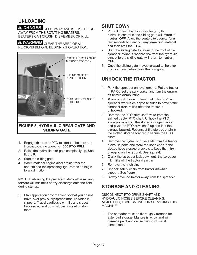
FIGURE 5. HYDRAULIC REAR GATE AND SLIDING GATE
HYDRAULIC REAR GATE IN RAISED POSITION
SLIDING GATE AT REAR POSITION
REAR GATE CYLINDER, BOTH SIDES
2. Allow the spreader to completely unload.3. Return the sliding gate to the front of the
spreader.4. To clean the spreader, raise the rear gate.
TURN OFF ALL POWER DURINGCLEANING AND INSPECTION. DO NOT USEPOWER TO MOVE ANY COMPONENTS OR TO DIS-CHARGE MATERIAL WHILE CLEANING OR IN-SPECTING.
5. Hose off manure from the outside and inside ofthe spreader. Completely clean manure frommoving mechanisms such as the beaters, wingedpulley, sliding gate, chain drive and rear gate.Remove accumulation in confined areas orpockets that trap manure.
6. Avoid directing high pressure spray directly onbearings, seals and flow control valve.
7. Keep high pressure spray moving on paintedsurfaces. Sustained spray on cracks or scratchesin paint can result in paint peeling.
8. Allow machine to dry.9. Lower rear gate completely down before storing
spreader.10. Inspect the spreader for loose connections,
damaged hydraulic hoses or connections and forother damaged components. Repair if necessaryso the spreader is ready for future operation.
Page 18
MAINTENANCE
PUT THE TRACTOR IN PARK, APPLY THE PARKING BRAKE, TURN OFF ENGINE AND REMOVE IGNITION KEY BEFORE CLEANING, ADJUSTING, LUBRICATING OR SERVICING THIS MA-
CHINE. FAILURE TO HEED MAY RESULT IN SERIOUS PERSONAL INJURY OR DEATH.
READ THE FOLLOWING BEFORE WELDING ON THIS MACHINE
1. When welding on your spreader, do not allow the
current to flow through the ball bearings or the
roller chains. Ground directly to the item being
welded.
2. The alternator shouwwld always be disconnected
if the spreader is not disconnected from the tow-
ing vehicle.
LUBRICATION
Bearings Grease 2 lower beater bearings and 2 wing pulley bearings every 100 hours of operation with 2 pumps of
grease. See figure 6.
PTO Drive
1. The PTO drive shaft yoke cross bearings must be
greased, both ends of assembly. Grease every 8
hrs of operation with one pump.
2. There is also a zerk at the center of the shaft
assembly to grease the telescoping shafts. It is
accessible through a slot in the guard. Grease
every 8 hrs of operation with 4 pumps.
Drive Chain Planetary Gearbox (See figure 7)
Oil Specification: Mobil Delvac Synthetic Gear Oil 75W-90.
There is a check plug half way up on the gearbox.
Maintain the oil level to this check plug. Fill plug is lo-
cated on the top of the gearbox.
DISCONNECT PTO DRIVE SHAFT AND HYDRAULIC HOSES BEFORE CLEANING, AD- JUSTING, LUBRICATING, OR SERVICING THIS MACHINE.
Page 19
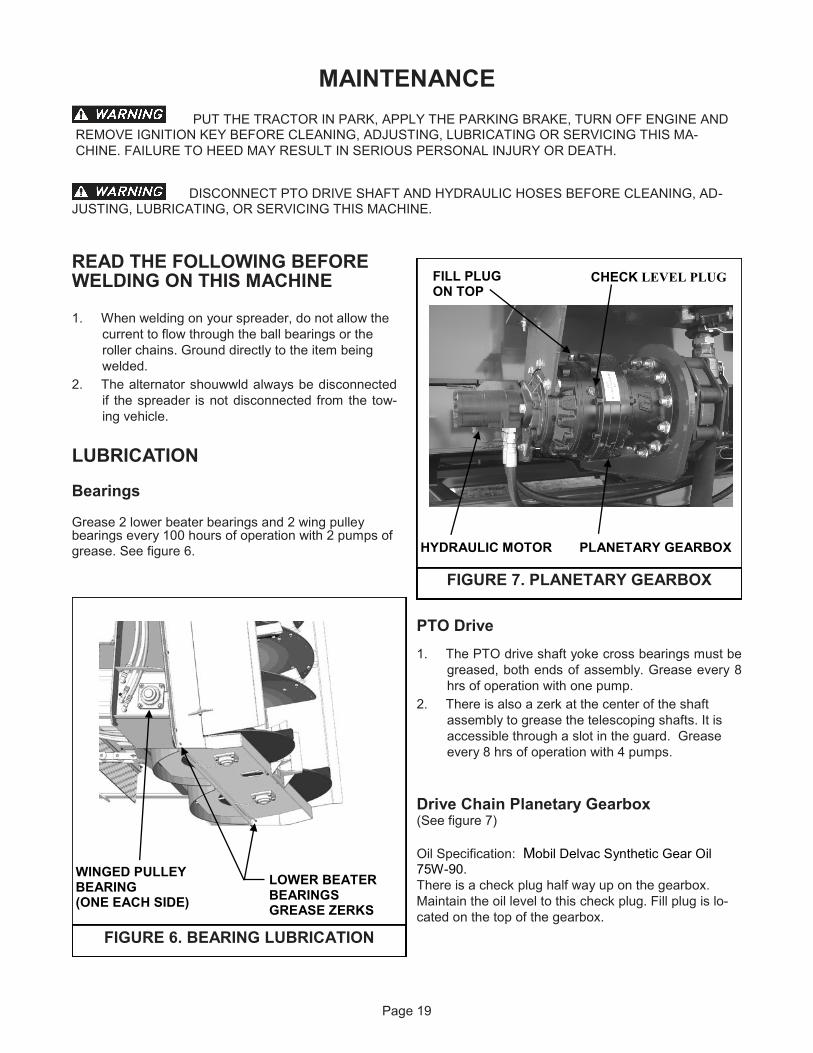
FIGURE 7. PLANETARY GEARBOX
FILL PLUG ON TOP
CHECK LEVEL PLUG
HYDRAULIC MOTOR PLANETARY GEARBOX
FIGURE 6. BEARING LUBRICATION
WINGED PULLEY BEARING (ONE EACH SIDE)
LOWER BEATER BEARINGS GREASE ZERKS
Page 20
Wheel Hubs Clean and repack wheel hubs annually with quality axle grease.
4. Check the oil level in the reservoir daily. It should be maintained 1” from the top level on the sight gauge.
5. Oil is added through a filter screen inside the filler neck. Before filling, remove the screen, inspect and clean if required.
6. Carefully clean dirt from the return filter head and element. Replace the filter element every 500 hrs of operation.
7. Drain reservoir and refill with new oil every 2000 hrs or annually, whichever occurs first. If the oil becomes contaminated and appears milky colored, replace immediately.
8. Every 100 hrs of operation, inspect all hydraulic hoses, hose connections, pump seals and motor seals for leakage. Tighten loose connections and replace damaged components.
9. A ball valve is provided at the bottom of the reservoir where the suction hose is connected. Turn this valve off to service hydraulic components. This prevents draining of the reservoir, however it is necessary to catch the oil that drains from disconnected hoses into a suitable container for proper disposal. Always check and refill the reservoir as required when servicing is completed.
Rear Gate Flashing (See figure 9)
1. Swinging gate flashing strips are clamped to both vertical ends of the rear gate frame. These strips must bear against the vertical box sides to minimize leakage.
2. To adjust, loosen the six 3/8" carriage bolts clamping the flashing.
3. Move the flashing strips so they contact against the box wall and retighten bolts.
FIGURE 8. HYDRAULIC RESERVOIR
FILLER CAP W/SCREEN SIGHT & TEMPERATURE GAUGE
RESERVOIR
SUCTION SCREEN
BALL VALVE
RETURN FILTER ELEMENT
FIGURE 9.
ADJUST REAR END GATE FLASHING
FLASHING STRIP
REAR END GATE FRAME
CLAMP
Page 21
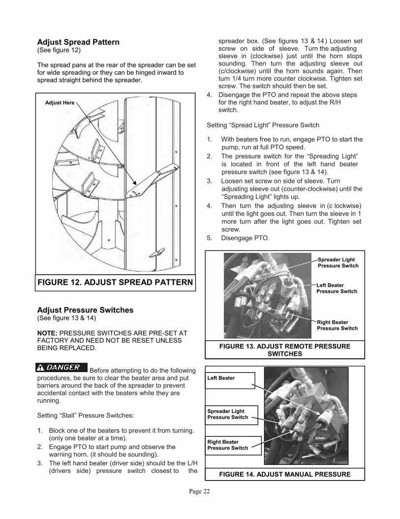
Drive Chain Slack
(See figure 6) 1. To adjust the floor drive chain, run the sliding
gate all the way to the rear of the spreader until it stops.
2. Remove the front panel of the sliding gate.
3. A threaded adjuster rod is provided where the drive chain attaches to the sliding gate. It is factory preset, but may require adjustment with usage. (CHECK CHAIN TENSION
WEEKLY)
4. Loosen the two 7/8” hex nuts on the end of the threaded rod. Tighten the inner nut until the forty eight Belleville washers are almost fully compressed (approximately 4-1/2”). Tighten the outer nut against the inner to lock the adjustment.
5. Replace the front panel.
NOTE: The Belleville washers are assembled in “tail to tail” pairs and stacked per figure 11.
4-1/2”
FIGURE 11. BELLVILLE SPRING WASHER STACK
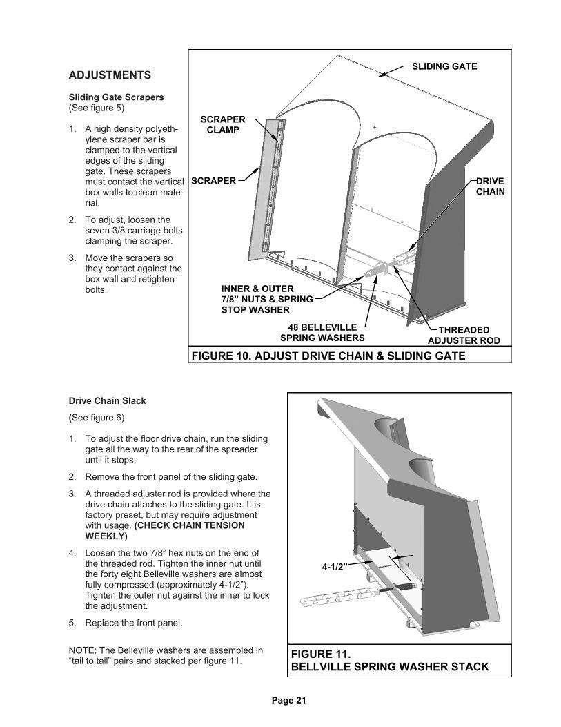
ADJUSTMENTS
Sliding Gate Scrapers (See figure 5) 1. A high density polyeth-
ylene scraper bar is clamped to the vertical edges of the sliding gate. These scrapers must contact the vertical box walls to clean mate-rial.
2. To adjust, loosen the seven 3/8 carriage bolts clamping the scraper.
3. Move the scrapers so they contact against the box wall and retighten bolts.
FIGURE 10. ADJUST DRIVE CHAIN & SLIDING GATE
SCRAPER CLAMP
SCRAPER
INNER & OUTER 7/8” NUTS & SPRING STOP WASHER
DRIVE CHAIN
48 BELLEVILLE SPRING WASHERS
SLIDING GATE
THREADED ADJUSTER ROD
Adjust Spread Pattern (See figure 12) The spread pans at the rear of the spreader can be set for wide spreading or they can be hinged inward to spread straight behind the spreader.
Adjust Pressure Switches (See figure 13 & 14) NOTE: PRESSURE SWITCHES ARE PRE-SET AT FACTORY AND NEED NOT BE RESET UNLESS BEING REPLACED.
Before attempting to do the following
procedures, be sure to clear the beater area and put barriers around the back of the spreader to prevent accidental contact with the beaters while they are running. Setting “Stall” Pressure Switches: 1. Block one of the beaters to prevent it from turning.
(only one beater at a time). 2. Engage PTO to start pump and observe the
warning horn. (it should be sounding). 3. The left hand beater (driver side) should be the L/H
(drivers side) pressure switch closest to the
spreader box. (See figures 13 & 14) Loosen set screw on side of sleeve. Turn the adjusting sleeve in (clockwise) just until the horn stops sounding. Then turn the adjusting sleeve out (c/clockwise) until the horn sounds again. Then turn 1/4 turn more counter clockwise. Tighten set screw. The switch should then be set.
4. Disengage the PTO and repeat the above steps for the right hand beater, to adjust the R/H switch.
Setting “Spread Light” Pressure Switch 1. With beaters free to run, engage PTO to start the
pump, run at full PTO speed. 2. The pressure switch for the “Spreading Light”
is located in front of the left hand beater pressure switch (see figure 13 & 14).
3. Loosen set screw on side of sleeve. Turn adjusting sleeve out (counter-clockwise) until the “Spreading Light” lights up.
4. Then turn the adjusting sleeve in (c lockwise) until the light goes out. Then turn the sleeve in 1 more turn after the light goes out. Tighten set screw.