Confidential Brother Color Laser Printer SERVICE REFERENCE MANUAL MODEL: HL-4040CN/4050CDN/4070CDW Read this manual thoroughly before maintenance work. Keep this manual in a convenient place for quick and easy reference at all times. January 2007 SM-PRN060 (6)
Transcript
Confidential
Brother Color Laser Printer SERVICE REFERENCE MANUAL
MODEL: HL-4040CN/4050CDN/4070CDW
Read this manual thoroughly before maintenance work.
Keep this manual in a convenient place for quick and easy reference at all times.
January 2007 SM-PRN060 (6)
i Confidential
PREFACE
This service reference manual contains basic information required for after-sales service of the laser printer (hereinafter referred to as "the machine"). This information is vital to the service personnel to maintain the high printing quality and performance of the machine.
This service reference manual covers the HL-4040CN/4050CDN/4070CDW machines.
This manual consists of the following chapters:
REFERENCE 1: SPECIFICATIONS Provides specifications of each model, which enables you to make a comparison of the different models.
REFERENCE 2: THEORY OF OPERATION Gives an overview of the printing mechanisms as well as the sensors, actuators, and control electronics. It aids in understanding the basic principles of operations as well as locating defects for troubleshooting.
APPENDIX 1: TONER CARTRIDGE WEIGHT INFORMATION
APPENDIX 2: REFERENCES
APPENDIX 3: GLOSSARY
Information in this manual is subject to change due to improvement or redesign of the product. All relevant information in such cases will be supplied in service information bulletins (Technical Information).
A thorough understanding of this machine, based on information in this service reference manual and service information bulletins, is required for maintaining the print quality performance and for improving the practical ability to find the cause of any problems.
Confidential ii
TABLE OF CONTENTS REFERENCE 1 SPECIFICATIONS....................................................Ref.1-1 1. COMPONENTS.................................................................................................... Ref.1-1 2. SPECIFICATIONS LIST ....................................................................................... Ref.1-2
2.1 Printing ..........................................................................................................................Ref.1-2 2.2 Functions.......................................................................................................................Ref.1-4 2.3 Electronics and Mechanics ...........................................................................................Ref.1-6 2.4 Network Connectivity ....................................................................................................Ref.1-7 2.5 Service Information .....................................................................................................Ref.1-10 2.6 Paper...........................................................................................................................Ref.1-11
2.6.1 Paper handling..................................................................................................Ref.1-11 2.6.2 Media specifications..........................................................................................Ref.1-11 2.6.3 Type and size of paper .....................................................................................Ref.1-12
2.8 Print Speeds with Various Settings.............................................................................Ref.1-17
REFERENCE 2 THEORY OF OPERATION ......................................Ref.2-1 1. GENERAL BLOCK DIAGRAM.............................................................................. Ref.2-1 2. ELECTRONICS GENERAL BLOCK DIAGRAM ................................................... Ref.2-2 3. MECHANICS ........................................................................................................ Ref.2-3
3.1 Cross-section Drawing ..................................................................................................Ref.2-3 3.2 Paper Feeding...............................................................................................................Ref.2-4
3.2.1 Plate-up Function of the Paper Tray...................................................................Ref.2-5 3.2.2 Paper Supply.......................................................................................................Ref.2-6 3.2.3 Paper Registration ..............................................................................................Ref.2-7 3.2.4 Paper Eject..........................................................................................................Ref.2-8 3.2.5 Paper Feeding for Duplex Printing (DX) (HL-4050CDN/ 4070CDW only) .........Ref.2-9 3.2.6 Paper Feeding from the MP Tray (MP).............................................................Ref.2-10 3.2.7 Paper Feeding from the Tray 2 (LT) (HL-4050CDN/ 4070CDW only)..............Ref.2-11
3.3 Toner Cartridge ...........................................................................................................Ref.2-12 3.3.1 Methods for Detecting and Counting Toner Life...............................................Ref.2-12 3.3.2 Toner Life End...................................................................................................Ref.2-13 3.3.3 New Toner Detection ........................................................................................Ref.2-17
3.4 Print .............................................................................................................................Ref.2-19 3.4.1 Principle of Color Overlapping ..........................................................................Ref.2-19 3.4.2 Basic Printing Principle .....................................................................................Ref.2-20 3.4.3 Print Process.....................................................................................................Ref.2-21 3.4.4 Switch between Color Print Mode and Monochrome Print Mode.....................Ref.2-27
Windows2000/XP/ XP Professional x64 Edition, Windows VistaTM, Windows Server 2003/ Windows Server 2003 x 64 Edition, Mac OS X 10.2.4 or greater
Resolution
600 x 600dpi Windows2000/XP/ XP Professional x64 Edition, Windows VistaTM, Windows Server 2003/ Windows Server 2003 x 64 Edition, Mac OS X 10.2.4 or greater, DOS, Linux
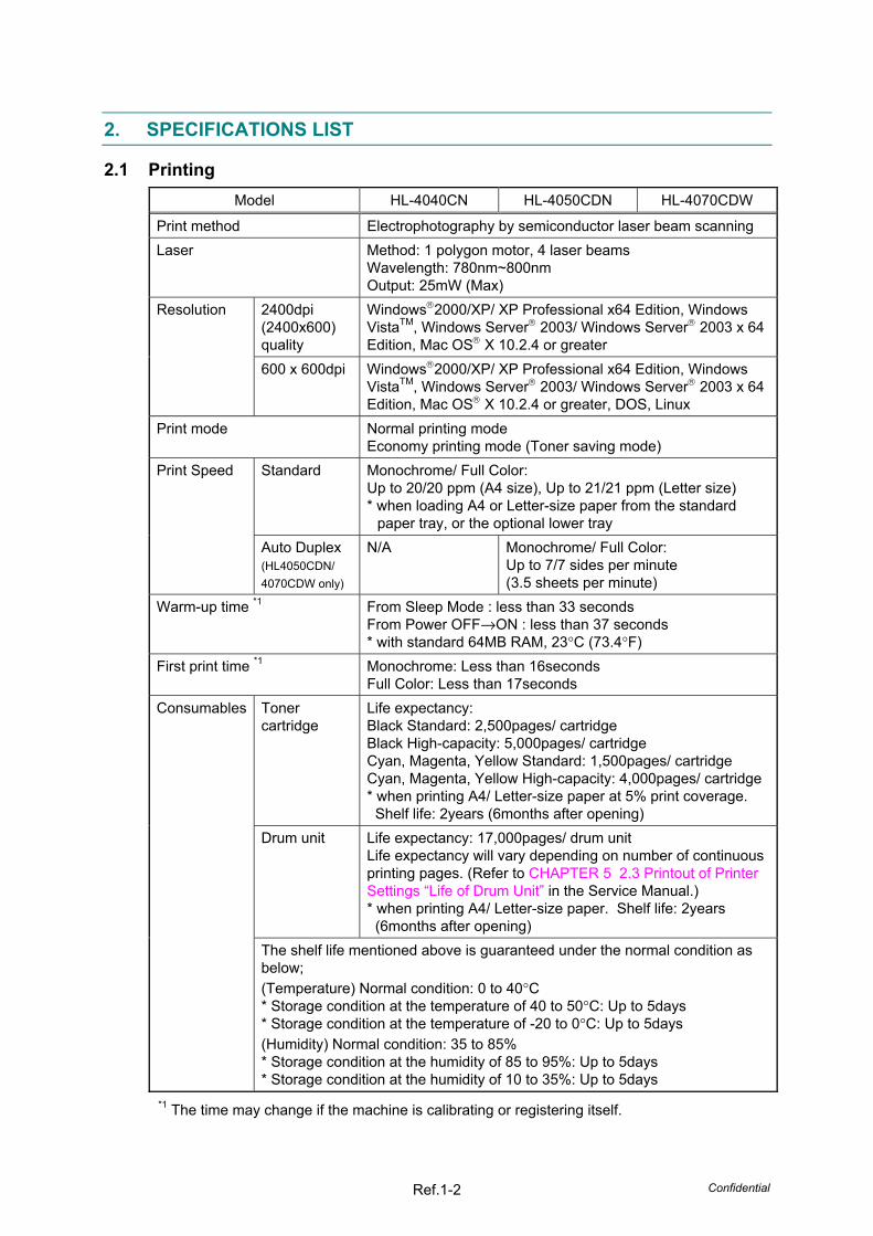
Standard Monochrome/ Full Color: Up to 20/20 ppm (A4 size), Up to 21/21 ppm (Letter size) * when loading A4 or Letter-size paper from the standard
paper tray, or the optional lower tray
Print Speed
Auto Duplex (HL4050CDN/ 4070CDW only)
N/A Monochrome/ Full Color: Up to 7/7 sides per minute (3.5 sheets per minute)
Warm-up time *1 From Sleep Mode : less than 33 seconds From Power OFF→ON : less than 37 seconds * with standard 64MB RAM, 23°C (73.4°F)
First print time *1 Monochrome: Less than 16seconds Full Color: Less than 17seconds
Toner cartridge
Life expectancy: Black Standard: 2,500pages/ cartridge Black High-capacity: 5,000pages/ cartridge Cyan, Magenta, Yellow Standard: 1,500pages/ cartridge Cyan, Magenta, Yellow High-capacity: 4,000pages/ cartridge * when printing A4/ Letter-size paper at 5% print coverage.
Shelf life: 2years (6months after opening) Drum unit Life expectancy: 17,000pages/ drum unit
Life expectancy will vary depending on number of continuous printing pages. (Refer to CHAPTER 5 2.3 Printout of Printer Settings “Life of Drum Unit” in the Service Manual.) * when printing A4/ Letter-size paper. Shelf life: 2years
(6months after opening)
Consumables
The shelf life mentioned above is guaranteed under the normal condition as below; (Temperature) Normal condition: 0 to 40°C * Storage condition at the temperature of 40 to 50°C: Up to 5days * Storage condition at the temperature of -20 to 0°C: Up to 5days (Humidity) Normal condition: 35 to 85% * Storage condition at the humidity of 85 to 95%: Up to 5days * Storage condition at the humidity of 10 to 35%: Up to 5days
*1 The time may change if the machine is calibrating or registering itself.
Confidential Ref.1-3
Model HL-4040CN HL-4050CDN HL-4070CDW
Belt unit Life expectancy: 50,000pages/ belt unit Life expectancy will vary depending on number of continuous printing pages. (Refer to CHAPTER 5 2.3 Printout of Printer Settings “Life of Belt Unit” in the Service Manual.) * when printing A4/ Letter-size paper.
Consumables
Waste toner box
Life expectancy: 20,000pages/ waste toner box * when printing A4/ Letter-size paper at 5% print coverage.
Note: Print speed varies depending on the paper size or media type. For details, refer to 2.8 ‘Print Speeds with Various Settings’ in this Chapter.
Confidential Ref.1-4
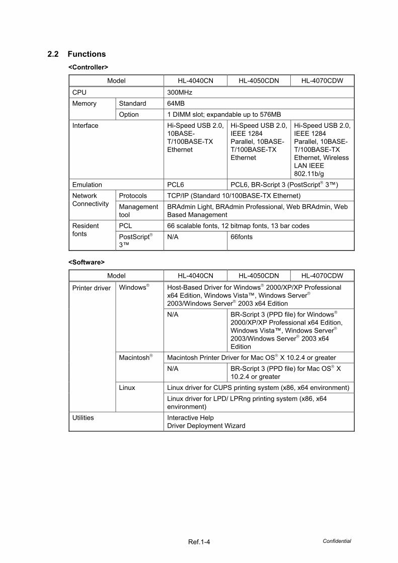
2.2 Functions <Controller>
Model HL-4040CN HL-4050CDN HL-4070CDW
CPU 300MHz Standard 64MB Memory Option 1 DIMM slot; expandable up to 576MB
Interface Hi-Speed USB 2.0, 10BASE-T/100BASE-TX Ethernet
Hi-Speed USB 2.0, IEEE 1284 Parallel, 10BASE-T/100BASE-TX Ethernet
Hi-Speed USB 2.0, IEEE 1284 Parallel, 10BASE-T/100BASE-TX Ethernet, Wireless LAN IEEE 802.11b/g
Host-Based Driver for Windows 2000/XP/XP Professional x64 Edition, Windows Vista™, Windows Server 2003/Windows Server 2003 x64 Edition
Windows
N/A BR-Script 3 (PPD file) for Windows 2000/XP/XP Professional x64 Edition, Windows Vista™, Windows Server 2003/Windows Server 2003 x64 Edition
Macintosh Printer Driver for Mac OS X 10.2.4 or greater Macintosh N/A BR-Script 3 (PPD file) for Mac OS X
10.2.4 or greater Linux driver for CUPS printing system (x86, x64 environment)
Printer driver
Linux Linux driver for LPD/ LPRng printing system (x86, x64 environment)
Utilities Interactive Help Driver Deployment Wizard
Confidential Ref.1-5
<Direct Print feature>
Model HL-4040CN HL-4050CDN HL-4070CDW
Direct Print PDF version1.6*, JPEG, Exif+JPEG, PRN (created by HL-4040CN or HL-4050CDN or HL-4070CDW printer driver), TIFF (scanned by all Brother MFC or DCP models)
PDF version1.6*, JPEG, Exif+JPEG, PRN (created by HL-4040CN or HL-4050CDN or HL-4070CDW printer driver), TIFF (scanned by all Brother MFC or DCP models), PostScript 3™(created by HL-4050CDN or HL-4070CDW BRScript3 printer driver)
* The data including JBIG2 image file, JPEG2000 image file and layered files are not supported.
<System requirements>
Computer Platform & Operating System Version
Processor Speed Minimum RAM
Recom-mended
RAM
Available Hard Disk
Space
2000 Professional
64MB 128MB 50MB
XP Home Edition XP Professional
IntelPentium or equivalent
128MB 256MB 50MB
XP Professional x64 Edition
AMDOpteron™ AMDAthlon™64 Intel Xeon with Intel
EM64T Intel Pentium 4 with Intel EM64T or equivalent
256MB 384MB 50MB
Vista™ Intel Pentium 4 or equivalent 64-bit supported CPU
512MB 1GB 50MB
Server 2003
Intel Pentium III or equivalent
256MB 512MB 50MB
Windows
Server 2003 x64 Edition
AMD Opteron™
AMD Athlon™ 64 Intel Xeon™ with Intel EM64T Intel Pentium with Intel EM64T or equivalent
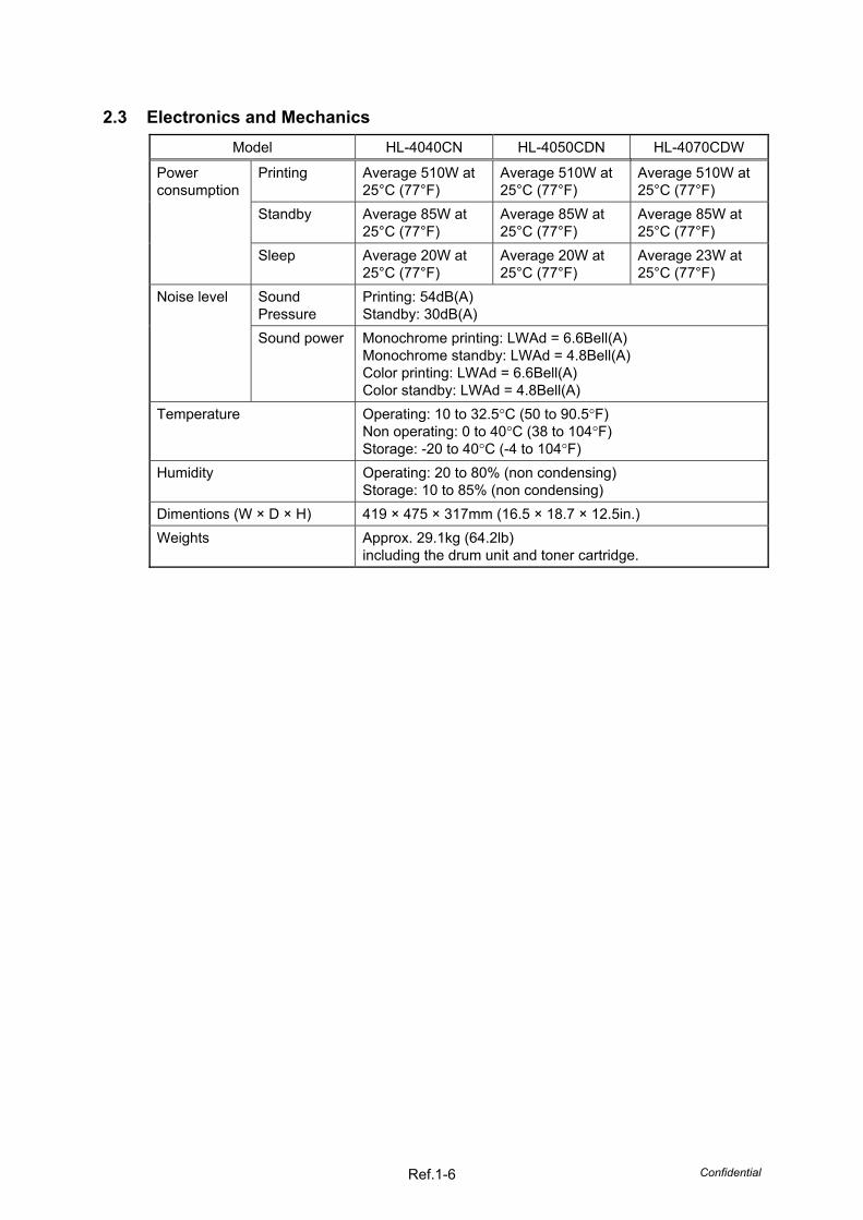
2.3 Electronics and Mechanics Model HL-4040CN HL-4050CDN HL-4070CDW
Printing Average 510W at 25°C (77°F)
Average 510W at 25°C (77°F)
Average 510W at 25°C (77°F)
Standby Average 85W at 25°C (77°F)
Average 85W at 25°C (77°F)
Average 85W at 25°C (77°F)
Power consumption
Sleep Average 20W at 25°C (77°F)
Average 20W at 25°C (77°F)
Average 23W at 25°C (77°F)
Sound Pressure
Printing: 54dB(A) Standby: 30dB(A)
Noise level
Sound power Monochrome printing: LWAd = 6.6Bell(A) Monochrome standby: LWAd = 4.8Bell(A) Color printing: LWAd = 6.6Bell(A) Color standby: LWAd = 4.8Bell(A)
Temperature Operating: 10 to 32.5°C (50 to 90.5°F) Non operating: 0 to 40°C (38 to 104°F) Storage: -20 to 40°C (-4 to 104°F)
Humidity Operating: 20 to 80% (non condensing) Storage: 10 to 85% (non condensing)
Dimentions (W × D × H) 419 × 475 × 317mm (16.5 × 18.7 × 12.5in.) Weights Approx. 29.1kg (64.2lb)
including the drum unit and toner cartridge.
Confidential Ref.1-7
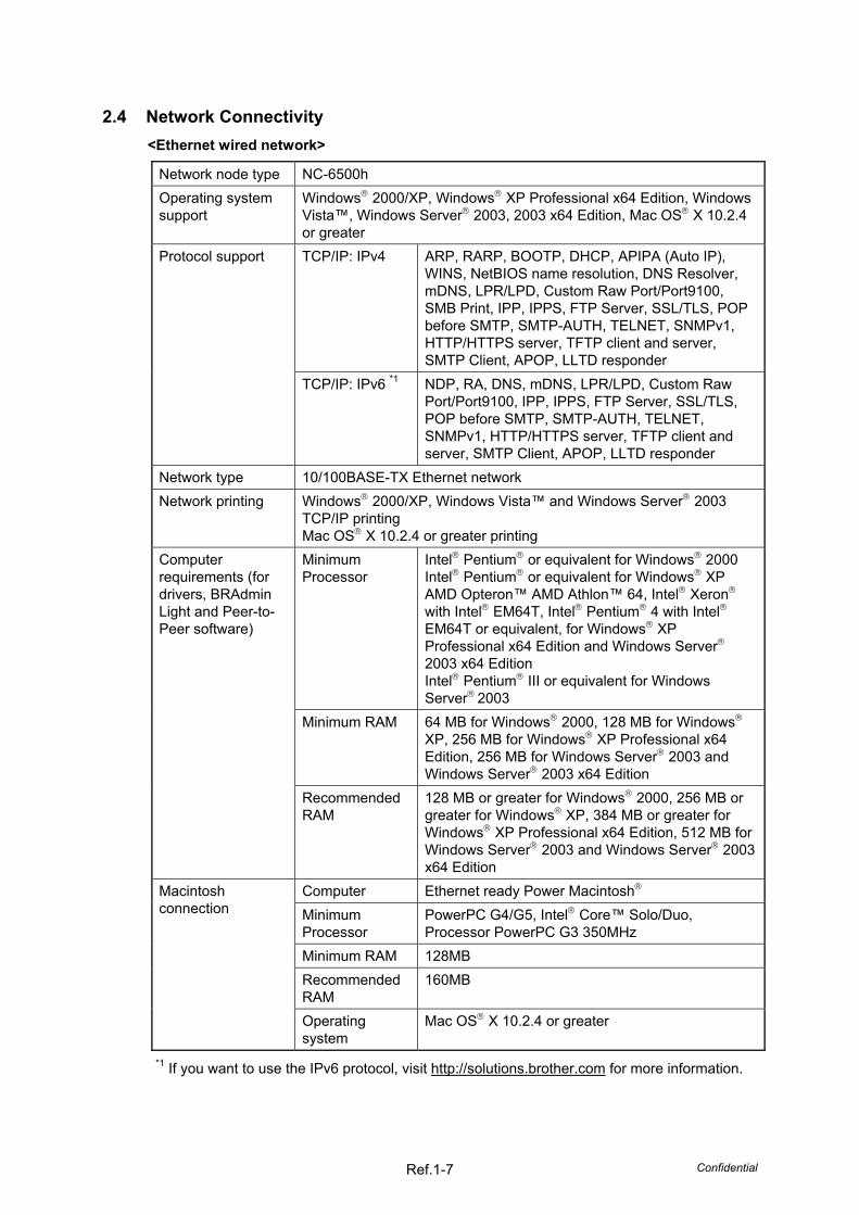
2.4 Network Connectivity <Ethernet wired network>
Network node type NC-6500h Operating system support
Windows 2000/XP, Windows XP Professional x64 Edition, Windows Vista™, Windows Server 2003, 2003 x64 Edition, Mac OS X 10.2.4 or greater TCP/IP: IPv4 ARP, RARP, BOOTP, DHCP, APIPA (Auto IP),
WINS, NetBIOS name resolution, DNS Resolver, mDNS, LPR/LPD, Custom Raw Port/Port9100, SMB Print, IPP, IPPS, FTP Server, SSL/TLS, POP before SMTP, SMTP-AUTH, TELNET, SNMPv1, HTTP/HTTPS server, TFTP client and server, SMTP Client, APOP, LLTD responder
Protocol support
TCP/IP: IPv6 *1 NDP, RA, DNS, mDNS, LPR/LPD, Custom Raw Port/Port9100, IPP, IPPS, FTP Server, SSL/TLS, POP before SMTP, SMTP-AUTH, TELNET, SNMPv1, HTTP/HTTPS server, TFTP client and server, SMTP Client, APOP, LLTD responder
Network type 10/100BASE-TX Ethernet network Network printing Windows 2000/XP, Windows Vista™ and Windows Server 2003
TCP/IP printing Mac OS X 10.2.4 or greater printing Minimum Processor
Intel Pentium or equivalent for Windows 2000 Intel Pentium or equivalent for Windows XP AMD Opteron™ AMD Athlon™ 64, Intel Xeron with Intel EM64T, Intel Pentium 4 with Intel EM64T or equivalent, for Windows XP Professional x64 Edition and Windows Server 2003 x64 Edition Intel Pentium III or equivalent for Windows Server 2003
Minimum RAM 64 MB for Windows 2000, 128 MB for Windows XP, 256 MB for Windows XP Professional x64 Edition, 256 MB for Windows Server 2003 and Windows Server 2003 x64 Edition
Computer requirements (for drivers, BRAdmin Light and Peer-to-Peer software)
Recommended RAM
128 MB or greater for Windows 2000, 256 MB or greater for Windows XP, 384 MB or greater for Windows XP Professional x64 Edition, 512 MB for Windows Server 2003 and Windows Server 2003 x64 Edition
Computer Ethernet ready Power Macintosh Minimum Processor
*1 If you want to use the IPv6 protocol, visit http://solutions.brother.com for more information.
Confidential Ref.1-8
Windows 2000/XP/XP Professional x64 Edition, Windows Vista™, Windows Server® 2003/2003 x64 Edition
BRAdmin Light
Mac OS X 10.2.4 or greater BRAdmin Professional *2
Windows 95/98/Me, Windows NT 4.0, Windows 2000/XP/XP Professional x64 Edition, Windows Vista™, Windows Server 2003/2003 x64 Edition
Management utilities
Web BRAdmin *2 Windows NT 4.0, Windows 2000 Professional / Server / Advanced Server, Windows XP Professional/XP Professional x64 Edition, Windows Vista™, Windows Server 2003/2003 x64 Edition
*2 BRAdmin Professional and Web BRAdmin are available as a download from http://solutions.brother.com
<Ethernet wireless network>
Network node type NC-7300w Operating system support
Windows 2000/XP, Windows XP Professional x64 Edition *1, Windows Vista™, Windows Server 2003, 2003 x64 Edition *1, Mac OS X 10.2.4 or greater TCP/IP: IPv4 ARP, RARP, BOOTP, DHCP, APIPA (Auto IP),
WINS, NetBIOS name resolution, DNS Resolver, mDNS, LPR/LPD, Custom Raw Port/Port9100, SMB Print, IPP, IPPS, FTP Server, SSL/TLS, POP before SMTP, SMTP-AUTH, TELNET, SNMPv1, HTTP/HTTPS server, TFTP client and server, SMTP Client, APOP, LLTD responder
Protocol support
TCP/IP: IPv6 *2 NDP, RA, DNS, mDNS, LPR/LPD, Custom Raw Port/Port9100, IPP, IPPS, FTP Server, SSL/TLS, POP before SMTP, SMTP-AUTH, TELNET, SNMPv1, HTTP/HTTPS server, TFTP client and server, SMTP Client, APOP, LLTD responder
Network type IEEE 802.11b/g wireless Frequency 2412-2472 MHz
US/Canada 1-11 Europe/Oceania 1-13
RF channels
Japan 802.11b: 1-14, 802.11g: 1-13 Communication mode
Infrastructure, Ad-hoc (802.11b only)
802.11b 11/5.5/2/1 Mbps Data rates 802.11g 54/48/36/24/18/12/11/9/6/5.5/2/1 Mbps
*1 A wireless network connection is supported only between the Brother printer and an access point for PC’s running Windows XP Professional x64 Edition and Windows Server 2003 x64 Edition.
*2 If you want to use the IPv6 protocol, visit http://solutions.brother.com for more information.
Confidential Ref.1-9
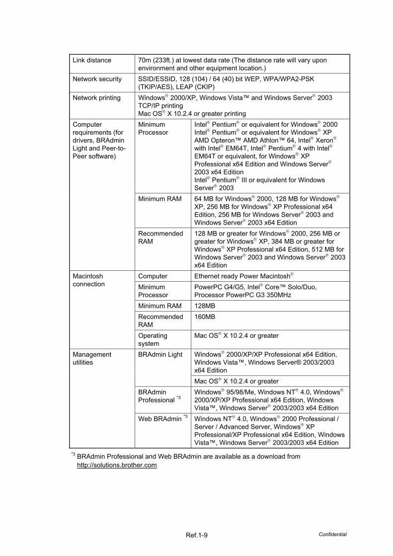
Link distance 70m (233ft.) at lowest data rate (The distance rate will vary upon
environment and other equipment location.) Network security SSID/ESSID, 128 (104) / 64 (40) bit WEP, WPA/WPA2-PSK
(TKIP/AES), LEAP (CKIP) Network printing Windows 2000/XP, Windows Vista™ and Windows Server 2003
TCP/IP printing Mac OS X 10.2.4 or greater printing Minimum Processor
Intel Pentium or equivalent for Windows 2000 Intel Pentium or equivalent for Windows XP AMD Opteron™ AMD Athlon™ 64, Intel Xeron with Intel EM64T, Intel Pentium 4 with Intel EM64T or equivalent, for Windows XP Professional x64 Edition and Windows Server 2003 x64 Edition Intel Pentium III or equivalent for Windows Server 2003
Minimum RAM 64 MB for Windows 2000, 128 MB for Windows XP, 256 MB for Windows XP Professional x64 Edition, 256 MB for Windows Server 2003 and Windows Server 2003 x64 Edition
Computer requirements (for drivers, BRAdmin Light and Peer-to-Peer software)
Recommended RAM
128 MB or greater for Windows 2000, 256 MB or greater for Windows XP, 384 MB or greater for Windows XP Professional x64 Edition, 512 MB for Windows Server 2003 and Windows Server 2003 x64 Edition
Computer Ethernet ready Power Macintosh Minimum Processor
Windows 2000/XP/XP Professional x64 Edition, Windows Vista™, Windows Server® 2003/2003 x64 Edition
BRAdmin Light
Mac OS X 10.2.4 or greater BRAdmin Professional *3
Windows 95/98/Me, Windows NT 4.0, Windows 2000/XP/XP Professional x64 Edition, Windows Vista™, Windows Server 2003/2003 x64 Edition
Management utilities
Web BRAdmin *3 Windows NT 4.0, Windows 2000 Professional / Server / Advanced Server, Windows XP Professional/XP Professional x64 Edition, Windows Vista™, Windows Server 2003/2003 x64 Edition
*3 BRAdmin Professional and Web BRAdmin are available as a download from http://solutions.brother.com
Confidential Ref.1-10
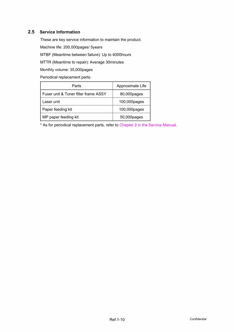
2.5 Service Information These are key service information to maintain the product.
Machine life: 200,000pages/ 5years
MTBF (Meantime between failure): Up to 4000hours
MTTR (Meantime to repair): Average 30minutes
Monthly volume: 35,000pages
Periodical replacement parts:
Parts Approximate Life
Fuser unit & Toner filter frame ASSY 80,000pages
Laser unit 100,000pages
Paper feeding kit 100,000pages
MP paper feeding kit 50,000pages
* As for periodical replacement parts, refer to Chapter 2 in the Service Manual.
Confidential Ref.1-11
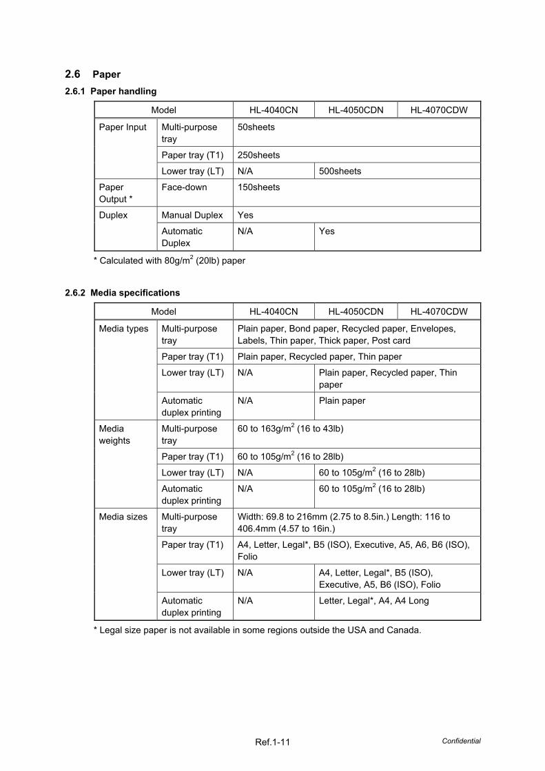
2.6 Paper 2.6.1 Paper handling
Model HL-4040CN HL-4050CDN HL-4070CDW
Multi-purpose tray
50sheets
Paper tray (T1) 250sheets
Paper Input
Lower tray (LT) N/A 500sheets
Paper Output *
Face-down 150sheets
Manual Duplex Yes Duplex
Automatic Duplex
N/A Yes
* Calculated with 80g/m2 (20lb) paper
2.6.2 Media specifications
Model HL-4040CN HL-4050CDN HL-4070CDW
Multi-purpose tray
Plain paper, Bond paper, Recycled paper, Envelopes, Labels, Thin paper, Thick paper, Post card
Paper tray (T1) Plain paper, Recycled paper, Thin paper
Lower tray (LT) N/A Plain paper, Recycled paper, Thin paper
Media types
Automatic duplex printing
N/A Plain paper
Multi-purpose tray
60 to 163g/m2 (16 to 43lb)
Paper tray (T1) 60 to 105g/m2 (16 to 28lb)
Lower tray (LT) N/A 60 to 105g/m2 (16 to 28lb)
Media weights
Automatic duplex printing
N/A 60 to 105g/m2 (16 to 28lb)
Multi-purpose tray
Width: 69.8 to 216mm (2.75 to 8.5in.) Length: 116 to 406.4mm (4.57 to 16in.)
* Legal size paper is not available in some regions outside the USA and Canada.
Confidential Ref.1-12
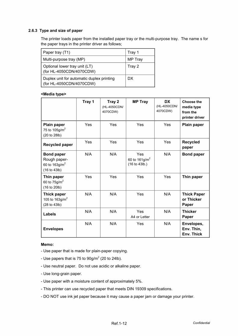
2.6.3 Type and size of paper
The printer loads paper from the installed paper tray or the multi-purpose tray. The name s for the paper trays in the printer driver as follows;
Paper tray (T1) Tray 1
Multi-purpose tray (MP) MP Tray
Optional lower tray unit (LT) (for HL-4050CDN/4070CDW)
Tray 2
Duplex unit for automatic duplex printing (for HL-4050CDN/4070CDW)
DX
<Media type>
Tray 1 Tray 2 (HL-4050CDN/4070CDW)
MP Tray DX (HL-4050CDN/ 4070CDW)
Choose the media type from the printer driver
Plain paper 75 to 105g/m2
(20 to 28lb)
Yes Yes Yes Yes Plain paper
Recycled paper Yes Yes Yes Yes Recycled paper
Bond paper Rough paper- 60 to 163g/m2
(16 to 43lb)
N/A N/A Yes 60 to 161g/m2
(16 to 43lb.)
N/A Bond paper
Thin paper 60 to 75g/m2
(16 to 20lb)
Yes Yes Yes Yes Thin paper
Thick paper 105 to 163g/m2
(28 to 43lb)
N/A N/A Yes N/A Thick Paper or Thicker Paper
Labels N/A N/A Yes A4 or Letter
N/A Thicker Paper
Envelopes N/A N/A Yes N/A Envelopes,
Env. Thin, Env. Thick
Memo: - Use paper that is made for plain-paper copying.
- Use papers that is 75 to 90g/m2 (20 to 24lb).
- Use neutral paper. Do not use acidic or alkaline paper.
- Use long-grain paper.
- Use paper with a moisture content of approximately 5%.
- This printer can use recycled paper that meets DIN 19309 specifications.
- DO NOT use ink jet paper because it may cause a paper jam or damage your printer.
Confidential Ref.1-13
2.7 Printable Area 2.7.1 PCL5e emulation
When using PCL emulation, the edges of the paper that cannot be printed on are shown below.
Portrait
A
B
C
D
E
F
GF
G
E
G G
Physical page
Printable areaLogical page
B Physical page length
D Maximum logical page length
F Distance from edge of physical page toedge of logical page
Note: - “Logical page” shows the printable area for a PCL driver.
- “Printable area” shows mechanical printable area of the machine.
- Therefore, the machine can only print within the shaded area when you use a PCL driver.
Confidential Ref.1-14
The table below shows the printable areas when printing on Portrait for each paper size. Size A B C D E F G
Letter 215.9mm 8.5” (2,550dots)
279.4mm 11.0” (3,300dots)
203.2mm 8.0” (2,400dots)
279.4mm 11.0” (3,300dots)
6.35mm 0.25” (75dots)
0mm 4.2mm 0.16” (50dots)
Legal 215.9mm 8.5” (2,550dots)
355.6mm 14.0” (4,200dots)
203.2mm 8.0” (2,400dots)
355.6mm 14.0” (4,200dots)
0mm
4.2mm 0.16” (50dots)
Folio 215.9mm 8.5” (2,550dots)
330.2mm 13.0” (3,900dots)
203.2mm 8.0” (2,400dots)
330.2mm 13.0” (3,900dots)
0mm
4.2mm 0.16” (50dots)
Executive 184.15mm 7.25” (2,175dots)
266.7mm 10.5” (3,150dots)
175.7mm 6.92” (2,025dots)
266.7mm 10.5” (3,150 dots)
6.35mm 0.25” (75dots)
0mm 4.2mm 0.16” (50dots)
A4 210.0mm 8.27” (2,480dots)
297.0mm 11.69” (3,507dots)
198.0mm 7.79” (2,338dots)
297.0mm 11.69” (3,507dots)
6.01mm 0.24” (71dots)
0mm 4.2mm 0.16” (50dots)
A5 148.5mm 5.85” (1,754dots)
210.0mm 8.27” (2,480dots)
136.5mm 5.37” (1,612dots)
210.0mm 8.27” (2,480dots)
0mm
4.2mm 0.16” (50dots)
A6 105.0mm 4.13” (1,240dots)
148.5mm 5.85” (1,754dots)
93.0mm 3.66” (1,098dots)
148.5mm 5.85” (1,754dots)
0mm
4.2mm 0.16” (50dots)
B5 (JIS) 182.0mm 7.1” (2,130dots)
257.0mm 10.11” (3,033dots)
170.0mm 6.69” (2,007dots)
257.0mm 10.11” (3,033dots)
0mm
4.2mm 0.16” (50dots)
B5 (ISO) 176.0mm 6.93” (2,078dots)
250.0mm 9.84” (2,952dots)
164.0mm 6.46” (1,936dots)
250.0mm 9.84” (2,952dots)
0mm
4.2mm 0.16” (50dots)
B6 (ISO) 125.0mm 4.92” (1,476dots)
176.0mm 6.93” (2,078dots)
164.0mm 4.44” (1,334dots)
176.0mm 6.93” (2.078dots)
0mm
4.2mm 0.16” (50dots)
Envelope Monarch
98.43mm 3.875” (1,162dots)
190.5mm 7.5” (2,250dots)
85.7mm 3.37” (1,012dots)
190.5mm 7.5” (2,250dots)
0mm
4.2mm 0.16” (50dots)
Envelope Com-10
104.7mm 4.12” (1,237dots)
241.3mm 9.5” (2,850dots)
92.0mm 3.62” (1,087dots)
241.3mm 9.5” (2,850dots)
6.35mm 0.25” (75dots)
0mm 4.2mm 0.16” (50dots)
Envelope DL 111.0mm 4.33” (1,299dots)
220.0mm 8.66” (2,598dots)
98.0mm 3.86” (1,157dots)
220.0mm 8.66” (2,598dots)
0mm
4.2mm 0.16” (50dots)
Envelope C5 162.0mm 6.38” (1,913dots)
229.0mm 9.01” (2,704dots)
150.0mm 5.9” (1,771dots)
229.0mm 9.01” (2,704dots)
6.01mm 0.24” (71dots)
0mm 4.2mm 0.16” (50dots)
Post Card 100.0mm 3.94” (1,181dots)
148.0mm 5.83” (1,748dots)
88.0mm 3.46” (1,039dots)
148.0mm 5.83” (1,748dots)
6.01mm 0.24” (71dots)
0mm 4.2mm 0.16” (50dots)
A4 Long 210.0mm 8.27” (2,480dots)
405.0mm 15.94” (4,783dots)
198.0mm 7,79” (2,338dots)
405.0mm 15.94” (4,783dots)
6.01mm 0.24” (71dots)
0mm 4.2mm 0.16” (50dots)
DL Long Edge
220.0mm 8.66” (2,598dots)
110.0mm 4.33” (1,299dots)
207.0mm 8.17” (2,450dots)
110.0mm 4.33” (1,299dots)
6.26mm 0.25” (74dots)
0mm 4.2mm 0.16” (50dots)
3X5 76.2mm 3.00” (900dots)
127.0mm 5.00” (1,500dots)
63.5mm 2.50” (750dots)
127.0mm 5.00” (1,500dots)
6.35mm 0.25” (75dots)
0mm 4.2mm 0.16” (50dots)
Organizer J 69.9mm 2.75” (825dots)
127.0mm 5.00” (1,500dots)
57.2mm 2.25” (675dots)
127.0mm 5.00” (1,500dots)
6.35mm 0.25” (75dots)
0mm 4.2mm 0.16” (50dots)
Organizer K 95.3mm 3.75” (1,125dots)
171.5mm 6.75” (2,025dots)
82.6mm 3.25” (975dots)
171.5mm 6.75” (2,025dots)
6.35mm 0.25” (75dots)
0mm 4.2mm 0.16” (50dots)
Organizer L 139.7mm 5.50” (1,650dots)
215.9mm 8.50” (2,550dots)
127.0mm 5.00” (1,500dots)
215.9mm 8.50” (2,550dots)
6.35mm 0.25” (75dots)
0mm 4.2mm 0.16” (50dots)
Organizer M 215.9mm 8.50” (2,550dots)
279.4mm 11.0” (3,300dots)
203.2mm 8.00” (2,400dots)
279.4mm 11.0” (3,300dots)
6.35mm 0.25” (75dots)
0mm 4.2mm 0.16” (50dots)
Note: - The paper sizes indicated here should confirm to the nominal dimensions specified by JIS
except B5 (ISO), B6 (ISO). - The dot size is based on 300dpi resolution.
Confidential Ref.1-15
Landscape
A
B
C
DE
F
GF
G
E
G G
Physical page
Printable area
Logical page
B Physical page length
D Maximum logical page length
F Distance from edge of physical page to edge of logical page
Note: - “Logical page” shows the printable area for a PCL driver.
- “Printable area” shows mechanical printable area of the machine.
- Therefore, the machine can only print within the shaded area when you use a PCL driver.
Confidential Ref.1-16
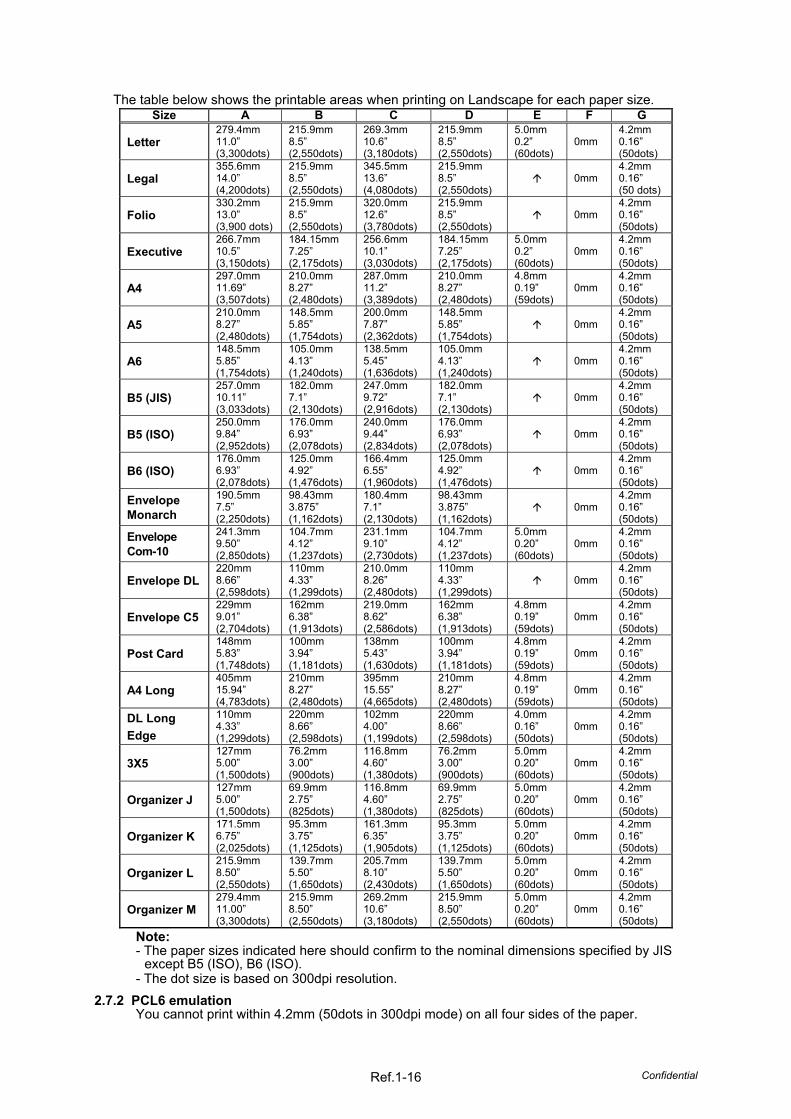
The table below shows the printable areas when printing on Landscape for each paper size. Size A B C D E F G
Letter 279.4mm 11.0” (3,300dots)
215.9mm 8.5” (2,550dots)
269.3mm 10.6” (3,180dots)
215.9mm 8.5” (2,550dots)
5.0mm 0.2” (60dots)
0mm 4.2mm 0.16” (50dots)
Legal 355.6mm 14.0” (4,200dots)
215.9mm 8.5” (2,550dots)
345.5mm 13.6” (4,080dots)
215.9mm 8.5” (2,550dots)
0mm
4.2mm 0.16” (50 dots)
Folio 330.2mm 13.0” (3,900 dots)
215.9mm 8.5” (2,550dots)
320.0mm 12.6” (3,780dots)
215.9mm 8.5” (2,550dots)
0mm
4.2mm 0.16” (50dots)
Executive 266.7mm 10.5” (3,150dots)
184.15mm 7.25” (2,175dots)
256.6mm 10.1” (3,030dots)
184.15mm 7.25” (2,175dots)
5.0mm 0.2” (60dots)
0mm 4.2mm 0.16” (50dots)
A4 297.0mm 11.69” (3,507dots)
210.0mm 8.27” (2,480dots)
287.0mm 11.2” (3,389dots)
210.0mm 8.27” (2,480dots)
4.8mm 0.19” (59dots)
0mm 4.2mm 0.16” (50dots)
A5 210.0mm 8.27” (2,480dots)
148.5mm 5.85” (1,754dots)
200.0mm 7.87” (2,362dots)
148.5mm 5.85” (1,754dots)
0mm
4.2mm 0.16” (50dots)
A6 148.5mm 5.85” (1,754dots)
105.0mm 4.13” (1,240dots)
138.5mm 5.45” (1,636dots)
105.0mm 4.13” (1,240dots)
0mm
4.2mm 0.16” (50dots)
B5 (JIS) 257.0mm 10.11” (3,033dots)
182.0mm 7.1” (2,130dots)
247.0mm 9.72” (2,916dots)
182.0mm 7.1” (2,130dots)
0mm
4.2mm 0.16” (50dots)
B5 (ISO) 250.0mm 9.84” (2,952dots)
176.0mm 6.93” (2,078dots)
240.0mm 9.44” (2,834dots)
176.0mm 6.93” (2,078dots)
0mm
4.2mm 0.16” (50dots)
B6 (ISO) 176.0mm 6.93” (2,078dots)
125.0mm 4.92” (1,476dots)
166.4mm 6.55” (1,960dots)
125.0mm 4.92” (1,476dots)
0mm
4.2mm 0.16” (50dots)
Envelope Monarch
190.5mm 7.5” (2,250dots)
98.43mm 3.875” (1,162dots)
180.4mm 7.1” (2,130dots)
98.43mm 3.875” (1,162dots)
0mm
4.2mm 0.16” (50dots)
Envelope Com-10
241.3mm 9.50” (2,850dots)
104.7mm 4.12” (1,237dots)
231.1mm 9.10” (2,730dots)
104.7mm 4.12” (1,237dots)
5.0mm 0.20” (60dots)
0mm 4.2mm 0.16” (50dots)
Envelope DL 220mm 8.66” (2,598dots)
110mm 4.33” (1,299dots)
210.0mm 8.26” (2,480dots)
110mm 4.33” (1,299dots)
0mm
4.2mm 0.16” (50dots)
Envelope C5 229mm 9.01” (2,704dots)
162mm 6.38” (1,913dots)
219.0mm 8.62” (2,586dots)
162mm 6.38” (1,913dots)
4.8mm 0.19” (59dots)
0mm 4.2mm 0.16” (50dots)
Post Card 148mm 5.83” (1,748dots)
100mm 3.94” (1,181dots)
138mm 5.43” (1,630dots)
100mm 3.94” (1,181dots)
4.8mm 0.19” (59dots)
0mm 4.2mm 0.16” (50dots)
A4 Long 405mm 15.94” (4,783dots)
210mm 8.27” (2,480dots)
395mm 15.55” (4,665dots)
210mm 8.27” (2,480dots)
4.8mm 0.19” (59dots)
0mm 4.2mm 0.16” (50dots)
DL Long Edge
110mm 4.33” (1,299dots)
220mm 8.66” (2,598dots)
102mm 4.00” (1,199dots)
220mm 8.66” (2,598dots)
4.0mm 0.16” (50dots)
0mm 4.2mm 0.16” (50dots)
3X5 127mm 5.00” (1,500dots)
76.2mm 3.00” (900dots)
116.8mm 4.60” (1,380dots)
76.2mm 3.00” (900dots)
5.0mm 0.20” (60dots)
0mm 4.2mm 0.16” (50dots)
Organizer J 127mm 5.00” (1,500dots)
69.9mm 2.75” (825dots)
116.8mm 4.60” (1,380dots)
69.9mm 2.75” (825dots)
5.0mm 0.20” (60dots)
0mm 4.2mm 0.16” (50dots)
Organizer K 171.5mm 6.75” (2,025dots)
95.3mm 3.75” (1,125dots)
161.3mm 6.35” (1,905dots)
95.3mm 3.75” (1,125dots)
5.0mm 0.20” (60dots)
0mm 4.2mm 0.16” (50dots)
Organizer L 215.9mm 8.50” (2,550dots)
139.7mm 5.50” (1,650dots)
205.7mm 8.10” (2,430dots)
139.7mm 5.50” (1,650dots)
5.0mm 0.20” (60dots)
0mm 4.2mm 0.16” (50dots)
Organizer M 279.4mm 11.00” (3,300dots)
215.9mm 8.50” (2,550dots)
269.2mm 10.6” (3,180dots)
215.9mm 8.50” (2,550dots)
5.0mm 0.20” (60dots)
0mm 4.2mm 0.16” (50dots)
Note: - The paper sizes indicated here should confirm to the nominal dimensions specified by JIS
except B5 (ISO), B6 (ISO). - The dot size is based on 300dpi resolution.
2.7.2 PCL6 emulation You cannot print within 4.2mm (50dots in 300dpi mode) on all four sides of the paper.
Confidential Ref.1-17
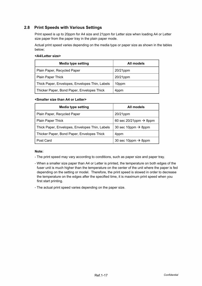
2.8 Print Speeds with Various Settings Print speed is up to 20ppm for A4 size and 21ppm for Letter size when loading A4 or Letter size paper from the paper tray in the plain paper mode.
Actual print speed varies depending on the media type or paper size as shown in the tables below;
Note: - The print speed may vary according to conditions, such as paper size and paper tray.
- When a smaller size paper than A4 or Letter is printed, the temperature on both edges of the fuser unit is much higher than the temperature on the center of the unit where the paper is fed depending on the setting or model. Therefore, the print speed is slowed in order to decrease the temperature on the edges after the specified time, it is maximum print speed when you first start printing.
- The actual print speed varies depending on the paper size.
Confidential Ref. 2-1
REFERENCE 2 THEORY OF OPERATION
1. GENERAL BLOCK DIAGRAM
Fig. Ref2-1
Confidential Ref. 2-2
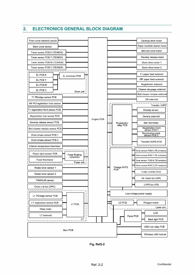
2. ELECTRONICS GENERAL BLOCK DIAGRAM
Fig. Ref2-2
Confidential Ref. 2-3
3. MECHANICS
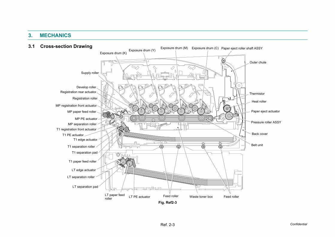
3.1 Cross-section Drawing
Fig. Ref2-3
Paper eject roller shaft ASSY
Outer chute
Exposure drum (C)
Thermistor
Heat roller
Paper eject actuator
Pressure roller ASSY
Back cover
Belt unit
Exposure drum (M)
Feed roller
Exposure drum (Y) Exposure drum (K)
T1 PE actuator
T1 paper feed roller
T1 separation pad
T1 separation roller
T1 edge actuator
T1 registration front actuatorMP separation roller
MP paper feed roller
MP PE actuator
MP registration front actuator
Registration roller
Registration rear actuatorDevelop roller
Supply roller
LT edge actuator
LT separation roller
LT paper feed roller LT PE actuator Waste toner box
LT separation pad
Feed roller
Confidential Ref. 2-4
3.2 Paper Feeding The following figure shows the paper feeding paths.
Fig. Ref2-4
Paper tray path
DX path
LT path
MP path
Confidential Ref. 2-5
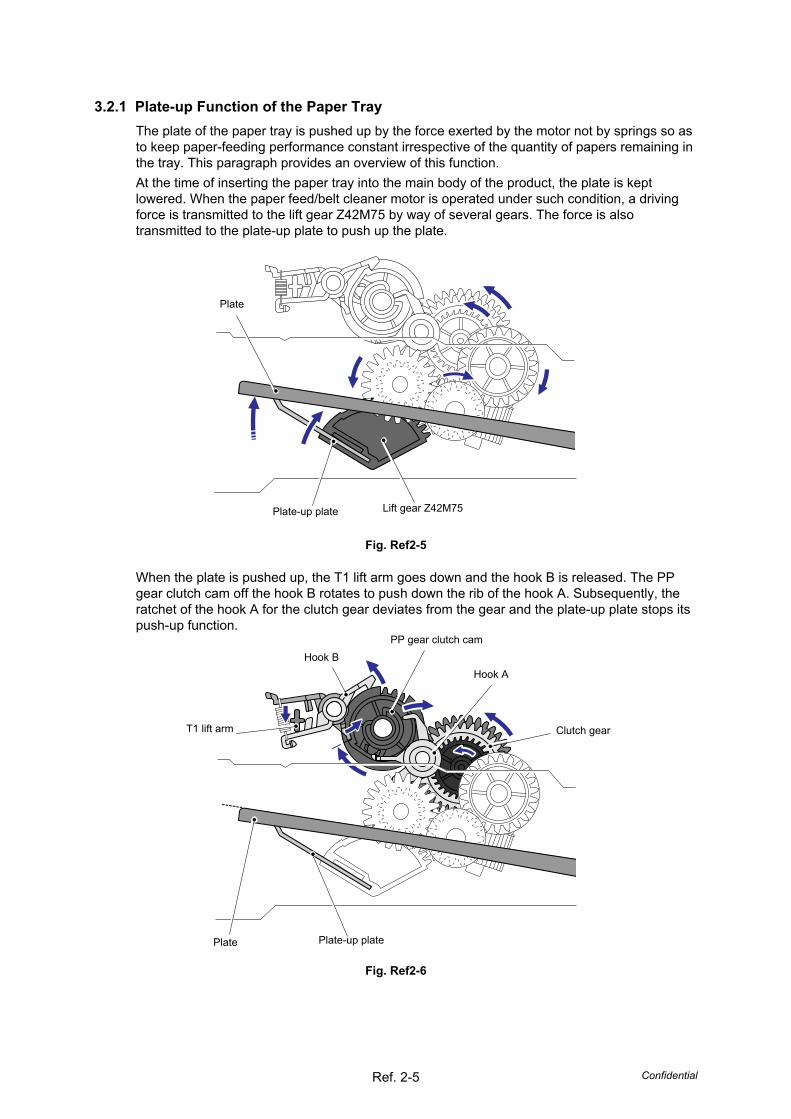
3.2.1 Plate-up Function of the Paper Tray The plate of the paper tray is pushed up by the force exerted by the motor not by springs so as to keep paper-feeding performance constant irrespective of the quantity of papers remaining in the tray. This paragraph provides an overview of this function. At the time of inserting the paper tray into the main body of the product, the plate is kept lowered. When the paper feed/belt cleaner motor is operated under such condition, a driving force is transmitted to the lift gear Z42M75 by way of several gears. The force is also transmitted to the plate-up plate to push up the plate.
Fig. Ref2-5
When the plate is pushed up, the T1 lift arm goes down and the hook B is released. The PP gear clutch cam off the hook B rotates to push down the rib of the hook A. Subsequently, the ratchet of the hook A for the clutch gear deviates from the gear and the plate-up plate stops its push-up function.
Fig. Ref2-6
Plate
Plate-up plate Lift gear Z42M75
PP gear clutch cam
Plate-up plate
T1 lift arm
Hook A
Plate
Clutch gear
Hook B
Confidential Ref. 2-6
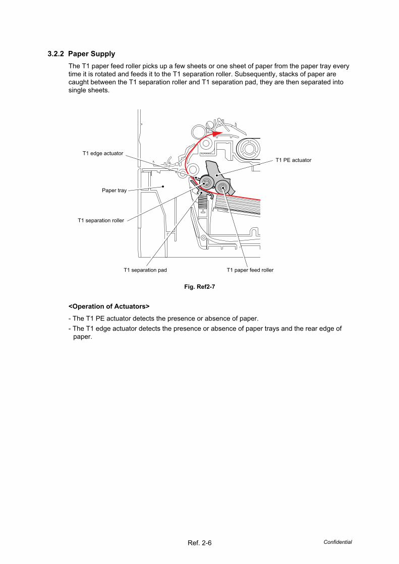
3.2.2 Paper Supply The T1 paper feed roller picks up a few sheets or one sheet of paper from the paper tray every time it is rotated and feeds it to the T1 separation roller. Subsequently, stacks of paper are caught between the T1 separation roller and T1 separation pad, they are then separated into single sheets.
Fig. Ref2-7
<Operation of Actuators>
- The T1 PE actuator detects the presence or absence of paper. - The T1 edge actuator detects the presence or absence of paper trays and the rear edge of
paper.
T1 PE actuator
T1 separation pad
T1 separation roller
T1 edge actuator
Paper tray
T1 paper feed roller
Confidential Ref. 2-7
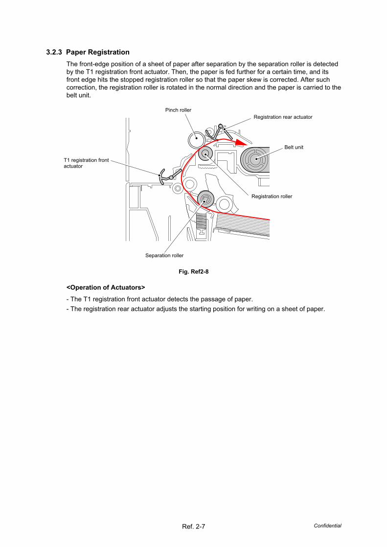
3.2.3 Paper Registration The front-edge position of a sheet of paper after separation by the separation roller is detected by the T1 registration front actuator. Then, the paper is fed further for a certain time, and its front edge hits the stopped registration roller so that the paper skew is corrected. After such correction, the registration roller is rotated in the normal direction and the paper is carried to the belt unit.
Fig. Ref2-8
<Operation of Actuators>
- The T1 registration front actuator detects the passage of paper. - The registration rear actuator adjusts the starting position for writing on a sheet of paper.
Belt unit
Separation roller
T1 registration front actuator
Pinch roller Registration rear actuator
Registration roller
Confidential Ref. 2-8
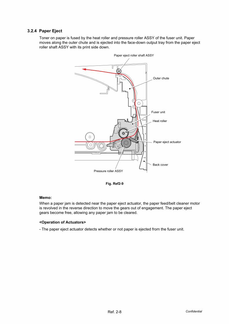
3.2.4 Paper Eject Toner on paper is fused by the heat roller and pressure roller ASSY of the fuser unit. Paper moves along the outer chute and is ejected into the face-down output tray from the paper eject roller shaft ASSY with its print side down.
Fig. Ref2-9
Memo: When a paper jam is detected near the paper eject actuator, the paper feed/belt cleaner motor is revolved in the reverse direction to move the gears out of engagement. The paper eject gears become free, allowing any paper jam to be cleared.
<Operation of Actuators>
- The paper eject actuator detects whether or not paper is ejected from the fuser unit.
Outer chute
Fuser unit
Paper eject roller shaft ASSY
Heat roller
Paper eject actuator
Pressure roller ASSY
Back cover
Confidential Ref. 2-9
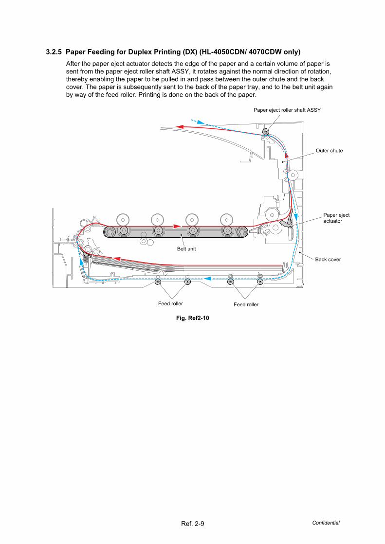
3.2.5 Paper Feeding for Duplex Printing (DX) (HL-4050CDN/ 4070CDW only) After the paper eject actuator detects the edge of the paper and a certain volume of paper is sent from the paper eject roller shaft ASSY, it rotates against the normal direction of rotation, thereby enabling the paper to be pulled in and pass between the outer chute and the back cover. The paper is subsequently sent to the back of the paper tray, and to the belt unit again by way of the feed roller. Printing is done on the back of the paper.
Fig. Ref2-10
Paper eject roller shaft ASSY
Outer chute
Feed roller
Back cover
Feed roller
Paper eject actuator
Belt unit
Confidential Ref. 2-10
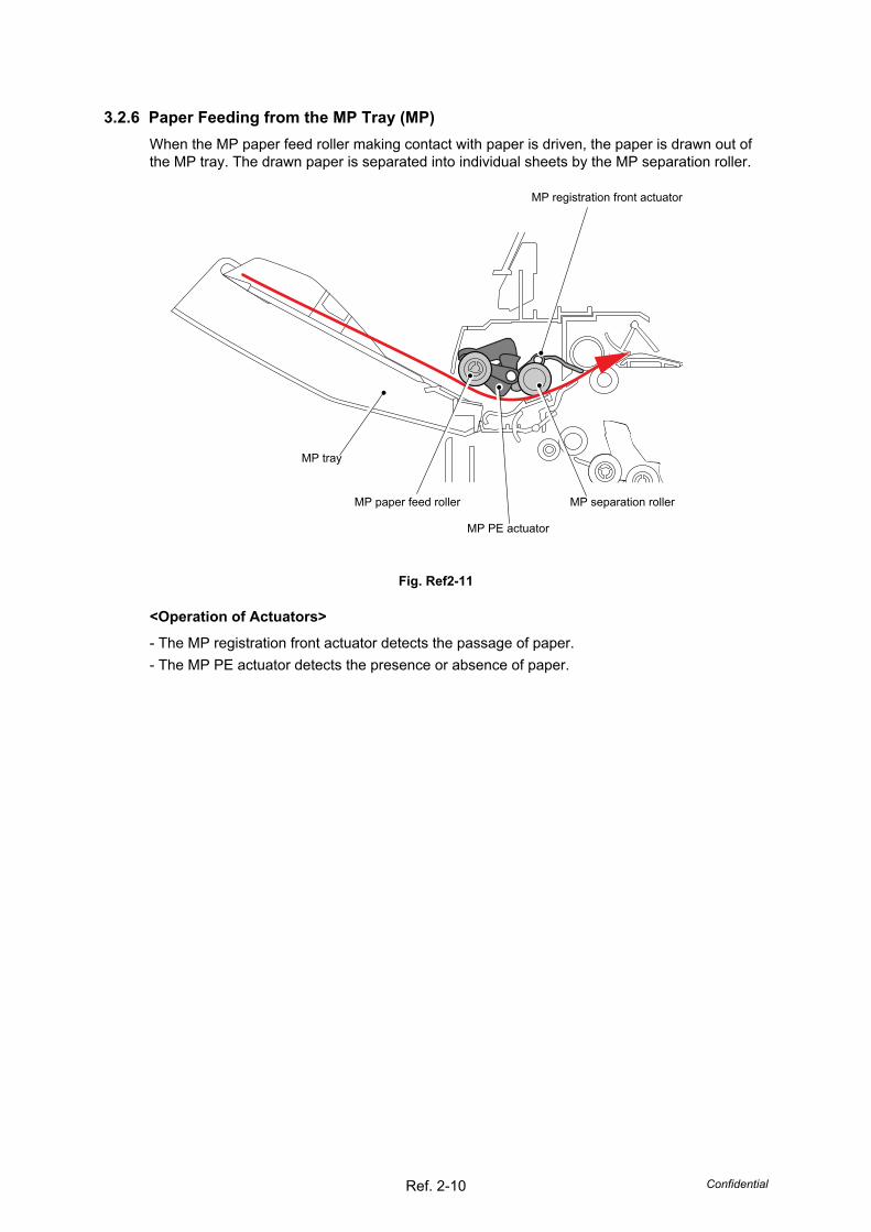
3.2.6 Paper Feeding from the MP Tray (MP) When the MP paper feed roller making contact with paper is driven, the paper is drawn out of the MP tray. The drawn paper is separated into individual sheets by the MP separation roller.
Fig. Ref2-11
<Operation of Actuators>
- The MP registration front actuator detects the passage of paper. - The MP PE actuator detects the presence or absence of paper.
MP PE actuator
MP separation roller
MP registration front actuator
MP paper feed roller
MP tray
Confidential Ref. 2-11
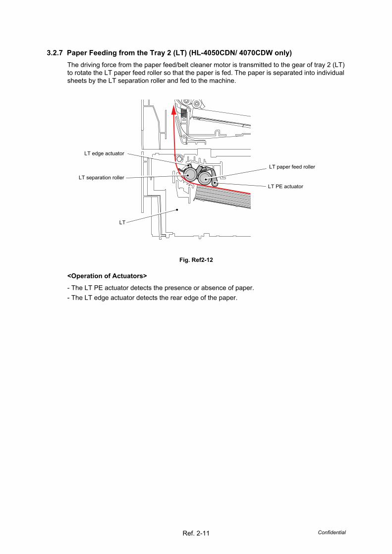
3.2.7 Paper Feeding from the Tray 2 (LT) (HL-4050CDN/ 4070CDW only) The driving force from the paper feed/belt cleaner motor is transmitted to the gear of tray 2 (LT) to rotate the LT paper feed roller so that the paper is fed. The paper is separated into individual sheets by the LT separation roller and fed to the machine.
Fig. Ref2-12
<Operation of Actuators>
- The LT PE actuator detects the presence or absence of paper. - The LT edge actuator detects the rear edge of the paper.
LT paper feed roller
LT
LT separation roller LT PE actuator
LT edge actuator
Confidential Ref. 2-12
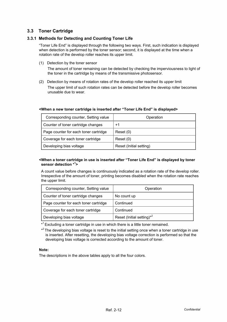
3.3 Toner Cartridge 3.3.1 Methods for Detecting and Counting Toner Life
“Toner Life End” is displayed through the following two ways. First, such indication is displayed when detection is performed by the toner sensor; second, it is displayed at the time when a rotation rate of the develop roller reaches its upper limit.
(1) Detection by the toner sensor The amount of toner remaining can be detected by checking the imperviousness to light of the toner in the cartridge by means of the transmissive photosensor.
(2) Detection by means of rotation rates of the develop roller reached its upper limit The upper limit of such rotation rates can be detected before the develop roller becomes unusable due to wear.
<When a new toner cartridge is inserted after “Toner Life End” is displayed>
Corresponding counter, Setting value Operation
Counter of toner cartridge changes +1
Page counter for each toner cartridge Reset (0)
Coverage for each toner cartridge Reset (0)
Developing bias voltage Reset (Initial setting)
<When a toner cartridge in use is inserted after “Toner Life End” is displayed by toner sensor detection *1>
A count value before changes is continuously indicated as a rotation rate of the develop roller. Irrespective of the amount of toner, printing becomes disabled when the rotation rate reaches the upper limit.
Corresponding counter, Setting value Operation
Counter of toner cartridge changes No count up
Page counter for each toner cartridge Continued
Coverage for each toner cartridge Continued
Developing bias voltage Reset (Initial setting)*2
*1 Excluding a toner cartridge in use in which there is a little toner remained. *2 The developing bias voltage is reset to the initial setting once when a toner cartridge in use
is inserted. After resetting, the developing bias voltage correction is performed so that the developing bias voltage is corrected according to the amount of toner.
Note: The descriptions in the above tables apply to all the four colors.
Confidential Ref. 2-13
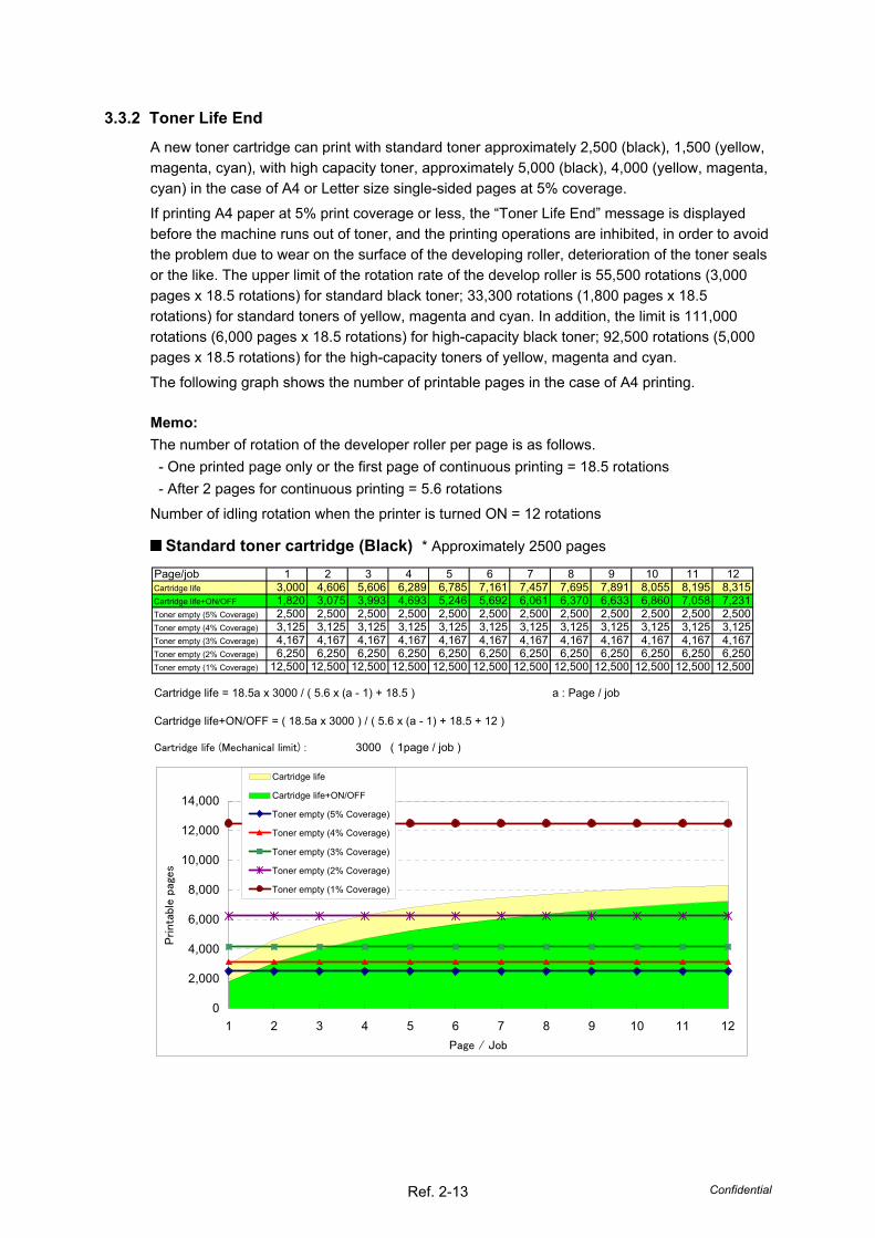
3.3.2 Toner Life End
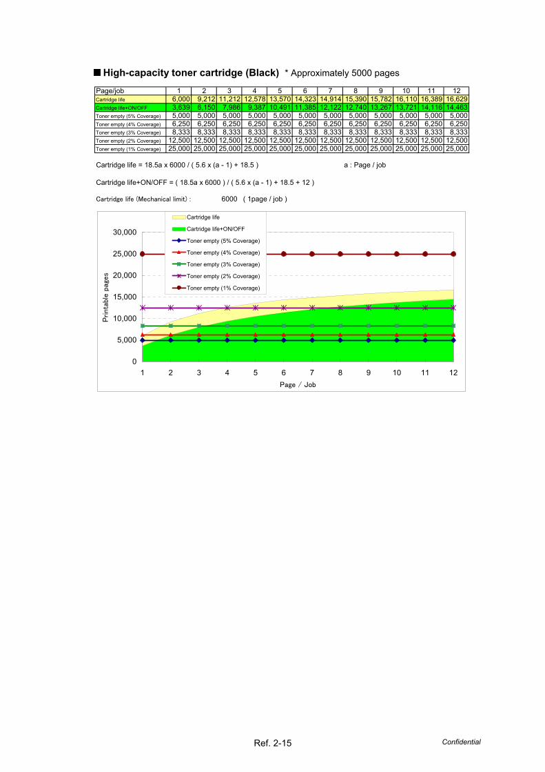
A new toner cartridge can print with standard toner approximately 2,500 (black), 1,500 (yellow, magenta, cyan), with high capacity toner, approximately 5,000 (black), 4,000 (yellow, magenta, cyan) in the case of A4 or Letter size single-sided pages at 5% coverage. If printing A4 paper at 5% print coverage or less, the “Toner Life End” message is displayed before the machine runs out of toner, and the printing operations are inhibited, in order to avoid the problem due to wear on the surface of the developing roller, deterioration of the toner seals or the like. The upper limit of the rotation rate of the develop roller is 55,500 rotations (3,000 pages x 18.5 rotations) for standard black toner; 33,300 rotations (1,800 pages x 18.5 rotations) for standard toners of yellow, magenta and cyan. In addition, the limit is 111,000 rotations (6,000 pages x 18.5 rotations) for high-capacity black toner; 92,500 rotations (5,000 pages x 18.5 rotations) for the high-capacity toners of yellow, magenta and cyan. The following graph shows the number of printable pages in the case of A4 printing.
Memo: The number of rotation of the developer roller per page is as follows.
- One printed page only or the first page of continuous printing = 18.5 rotations - After 2 pages for continuous printing = 5.6 rotations
Number of idling rotation when the printer is turned ON = 12 rotations
When a toner cartridge is changed, discrimination between new and secondhand toner cartridges is performed by means of the new toner detection mechanism shown below.
<New Toner Detection Mechanism> The rotation of the gear (1) of the toner cartridge is transmitted to the reset gear, and the rib of the gear pushes down the reset upper lever attached to the drum unit. By pushing down the reset upper lever, the linked reset lever turns and pushes up the new toner actuator with its lever fitted on the main body. The detection mechanism detects that new toner is provided.
- For high-capacity toner cartridges The reset gear has two ribs. The new toner actuator is pushed up twice by these ribs, allowing the presence of a high-capacity toner cartridge to be detected.
- For standard toner cartridges The reset gear has one rib. The new toner actuator is pushed up once by this rib, allowing the presence of a standard toner cartridge to be detected.
Fig. Ref2-13
Reset gear
Reset lever
Rib
Rib
Reset gear
Gear (1)
Rib
Rib Reset gear
New toner actuator
Reset upper lever
Reset lever
* The figure shows a high-capacity toner cartridge.
Drum unit
Drum unit
Confidential Ref. 2-18
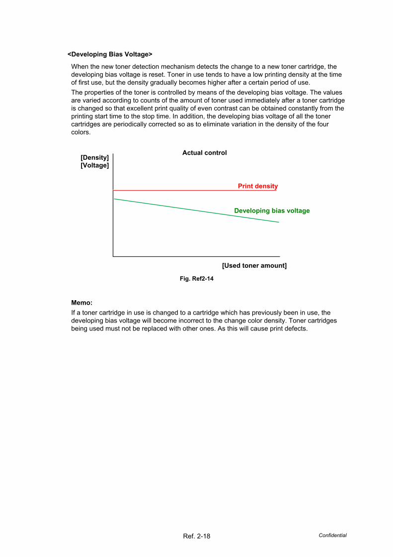
<Developing Bias Voltage>
When the new toner detection mechanism detects the change to a new toner cartridge, the developing bias voltage is reset. Toner in use tends to have a low printing density at the time of first use, but the density gradually becomes higher after a certain period of use. The properties of the toner is controlled by means of the developing bias voltage. The values are varied according to counts of the amount of toner used immediately after a toner cartridge is changed so that excellent print quality of even contrast can be obtained constantly from the printing start time to the stop time. In addition, the developing bias voltage of all the toner cartridges are periodically corrected so as to eliminate variation in the density of the four colors.
Fig. Ref2-14
Memo: If a toner cartridge in use is changed to a cartridge which has previously been in use, the developing bias voltage will become incorrect to the change color density. Toner cartridges being used must not be replaced with other ones. As this will cause print defects.
[Used toner amount]
Developing bias voltage
Print density
Actual control [Density] [Voltage]
Confidential Ref. 2-19
3.4 Print 3.4.1 Principle of Color Overlapping
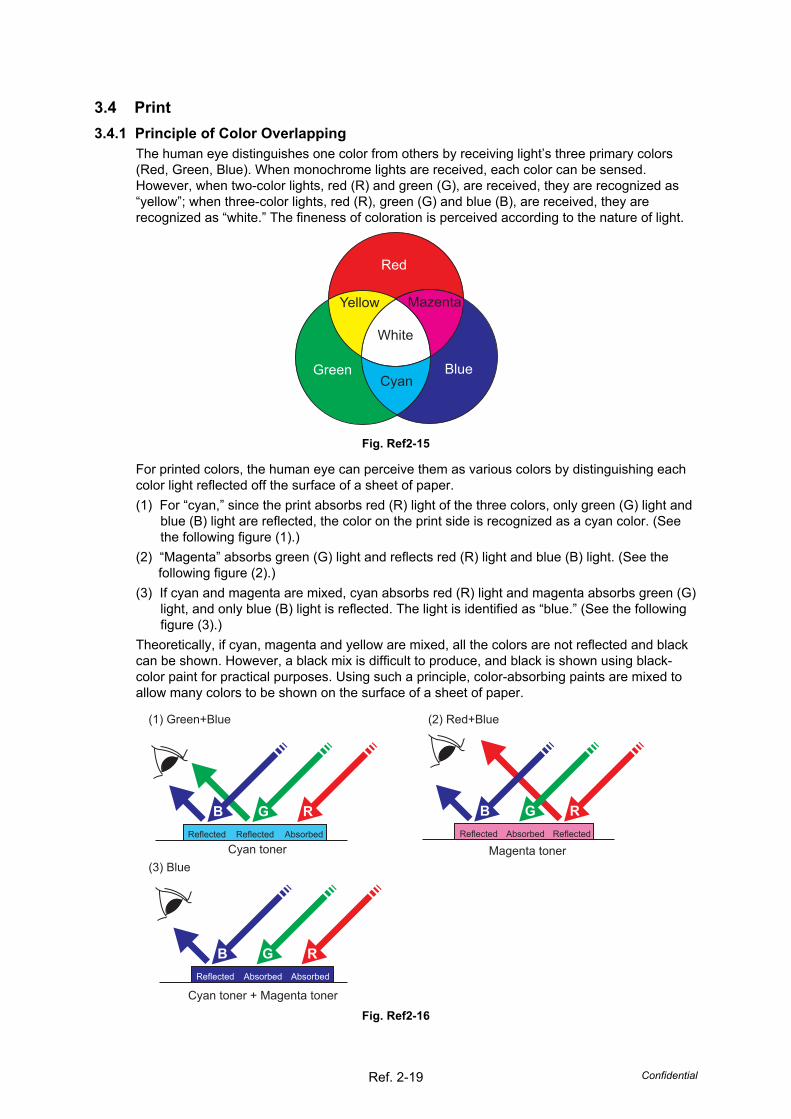
The human eye distinguishes one color from others by receiving light’s three primary colors (Red, Green, Blue). When monochrome lights are received, each color can be sensed. However, when two-color lights, red (R) and green (G), are received, they are recognized as “yellow”; when three-color lights, red (R), green (G) and blue (B), are received, they are recognized as “white.” The fineness of coloration is perceived according to the nature of light.
Red
Green Blue
White
Yellow
Cyan
Mazenta
Fig. Ref2-15
For printed colors, the human eye can perceive them as various colors by distinguishing each color light reflected off the surface of a sheet of paper. (1) For “cyan,” since the print absorbs red (R) light of the three colors, only green (G) light and
blue (B) light are reflected, the color on the print side is recognized as a cyan color. (See the following figure (1).)
(2) “Magenta” absorbs green (G) light and reflects red (R) light and blue (B) light. (See the following figure (2).)
(3) If cyan and magenta are mixed, cyan absorbs red (R) light and magenta absorbs green (G) light, and only blue (B) light is reflected. The light is identified as “blue.” (See the following figure (3).)
Theoretically, if cyan, magenta and yellow are mixed, all the colors are not reflected and black can be shown. However, a black mix is difficult to produce, and black is shown using black-color paint for practical purposes. Using such a principle, color-absorbing paints are mixed to allow many colors to be shown on the surface of a sheet of paper.
AbsorbedReflected Reflected
Cyan toner
AbsorbedReflected
Cyan toner + Magenta tonerAbsorbed
Absorbed ReflectedReflected
Magenta toner
(1) Green+Blue
(3) Blue
(2) Red+Blue
B G RB G R
B G R
Fig. Ref2-16
Confidential Ref. 2-20
3.4.2 Basic Printing Principle The printing process consists broadly of 6 processes: Charging, Exposure, Development, Transfer, Fusing and Cleaning.
1. Charging: The surface of the drum is electrically charged (Primary Charge). 2. Exposure: A printed image is formed on the surface of the drum by applying laser beam
(Electrostatic Latent Image). 3. Development: Toner is adhered to the surface of the drum (Visible Image). 4. Transfer: The toner on the surface of the exposure drum is transferred to the paper. 5. Fusing: The transferred toner is fused on to the paper. 6. Cleaning: Toner remaining on the exposure drum and belt unit is removed for recovery.
After these processes, the image is printed on the paper.
CMYK
Charging Exposure Development Transfer
Fusing
Cleaning
Fig. Ref2-17
Confidential Ref. 2-21
3.4.3 Print Process 1. Charging
The flow of the ion charge is controlled by the constant voltage of the grid 870 V to ensure it is distributed evenly on the drum surface. In order to coat toner on the exposure drum, the drum needs to be evenly electrified. Ions are produced by supplying high-voltage power to the corona wire.
Fig. Ref2-18
Memo: The level of ozone expelled from the printer is less than 3.0 mg/h therefore not harmful to the human body. Applicable safety standards have been complied with.
Corona wire
Ion
Grid Exposure drum
Confidential Ref. 2-22
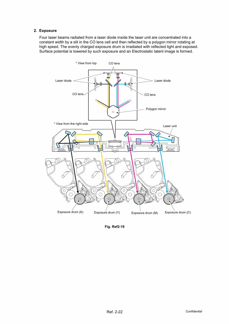
2. Exposure Four laser beams radiated from a laser diode inside the laser unit are concentrated into a constant width by a slit in the CO lens cell and then reflected by a polygon mirror rotating at high speed. The evenly charged exposure drum is irradiated with reflected light and exposed. Surface potential is lowered by such exposure and an Electrostatic latent image is formed.
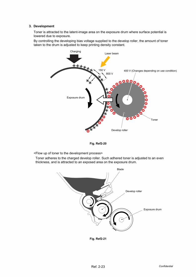
3. Development Toner is attracted to the latent-image area on the exposure drum where surface potential is lowered due to exposure. By controlling the developing bias voltage supplied to the develop roller, the amount of toner taken to the drum is adjusted to keep printing density constant.
Fig. Ref2-20
<Flow up of toner to the development process> Toner adheres to the charged develop roller. Such adhered toner is adjusted to an even thickness, and is attracted to an exposed area on the exposure drum.
Fig. Ref2-21
400 V (Changes depending on use condition)
Develop roller
800 V 150 V
Laser beam
Exposure drum
Charging
Exposure drum
Develop roller
Blade
Toner
Confidential Ref. 2-24
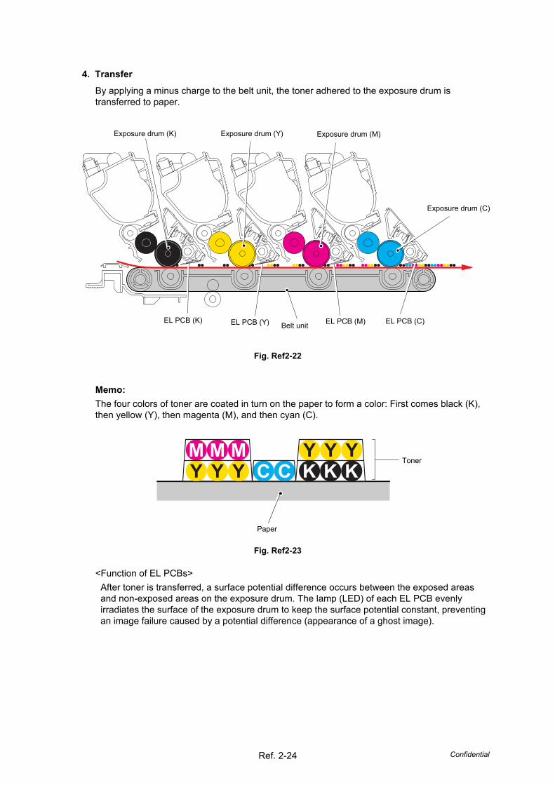
4. Transfer By applying a minus charge to the belt unit, the toner adhered to the exposure drum is transferred to paper.
Fig. Ref2-22
Memo: The four colors of toner are coated in turn on the paper to form a color: First comes black (K), then yellow (Y), then magenta (M), and then cyan (C).
Fig. Ref2-23
<Function of EL PCBs> After toner is transferred, a surface potential difference occurs between the exposed areas and non-exposed areas on the exposure drum. The lamp (LED) of each EL PCB evenly irradiates the surface of the exposure drum to keep the surface potential constant, preventing an image failure caused by a potential difference (appearance of a ghost image).
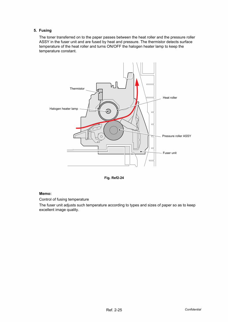
5. Fusing The toner transferred on to the paper passes between the heat roller and the pressure roller ASSY in the fuser unit and are fused by heat and pressure. The thermistor detects surface temperature of the heat roller and turns ON/OFF the halogen heater lamp to keep the temperature constant.
Fig. Ref2-24
Memo: Control of fusing temperature The fuser unit adjusts such temperature according to types and sizes of paper so as to keep excellent image quality.
Thermistor
Halogen heater lamp
Heat roller
Pressure roller ASSY
Fuser unit
Confidential Ref. 2-26
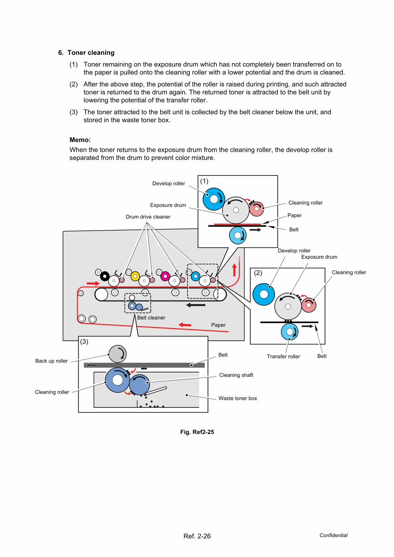
6. Toner cleaning (1) Toner remaining on the exposure drum which has not completely been transferred on to
the paper is pulled onto the cleaning roller with a lower potential and the drum is cleaned.
(2) After the above step, the potential of the roller is raised during printing, and such attracted toner is returned to the drum again. The returned toner is attracted to the belt unit by lowering the potential of the transfer roller.
(3) The toner attracted to the belt unit is collected by the belt cleaner below the unit, and stored in the waste toner box.
Memo: When the toner returns to the exposure drum from the cleaning roller, the develop roller is separated from the drum to prevent color mixture.
Fig. Ref2-25
Cleaning roller
Transfer roller
Paper
Belt
Exposure drum
Belt
Cleaning shaft
Back up roller
Cleaning roller
Belt cleaner
Drum drive cleaner
Paper
Develop roller
Belt
Exposure drum Develop roller
Cleaning roller
(1)
(2)
(3)
Waste toner box
Confidential Ref. 2-27
3.4.4 Switch between Color Print Mode and Monochrome Print Mode By switching the mode between color print and monochrome print to avoid unnecessary load on the toner cartridges and keep the specified product life, the rotation and press/release operations of the develop roller are controlled, and the print operation is executed.
<Rotation of the develop roller> The gear is driven by the develop drive motor through the clockwise or counterclockwise rotation, and all four develop rollers for four colors (K, Y, M, C) rotate in the color print mode, and the one develop roller for the black color (K) only rotates in the monochrome print mode.
<Press/release operations of the develop roller> By rotation of the develop release motor, all four develop rollers for four colors (K, Y, M, C) press corresponding exposure drums respectively in the color print mode, and the one develop roller for the black color (K) only presses the corresponding exposure drum and the remaining three develop rollers for three colors (Y, M, C) are kept separated from the exposure drums in the monochrome print mode.
Confidential App.1-1
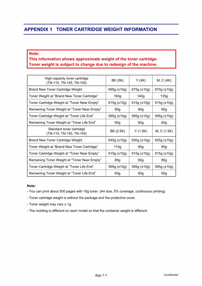
APPENDIX 1 TONER CARTRIDGE WEIGHT INFORMATION
Note: This information shows approximate weight of the toner cartridge. Toner weight is subject to change due to redesign of the machine.
Toner Weight at “Brand New Toner Cartridge” 110g 95g 90g
Toner Cartridge Weight at “Toner Near Empty” 615g (±10g) 615g (±10g) 615g (±10g)
Remaining Toner Weight at “Toner Near Empty” 80g 80g 80g
Toner Cartridge Weight at “Toner Life End” 595g (±10g) 595g (±10g) 595g (±10g)
Remaining Toner Weight at “Toner Life End” 60g 60g 60g
Note: - You can print about 500 pages with 10g toner. (A4 size, 5% coverage, continuous printing)
- Toner cartridge weight is without the package and the protective cover.
- Toner weight may vary ± 1g.
- The molding is different on each model so that the container weight is different.
Confidential App.2-1
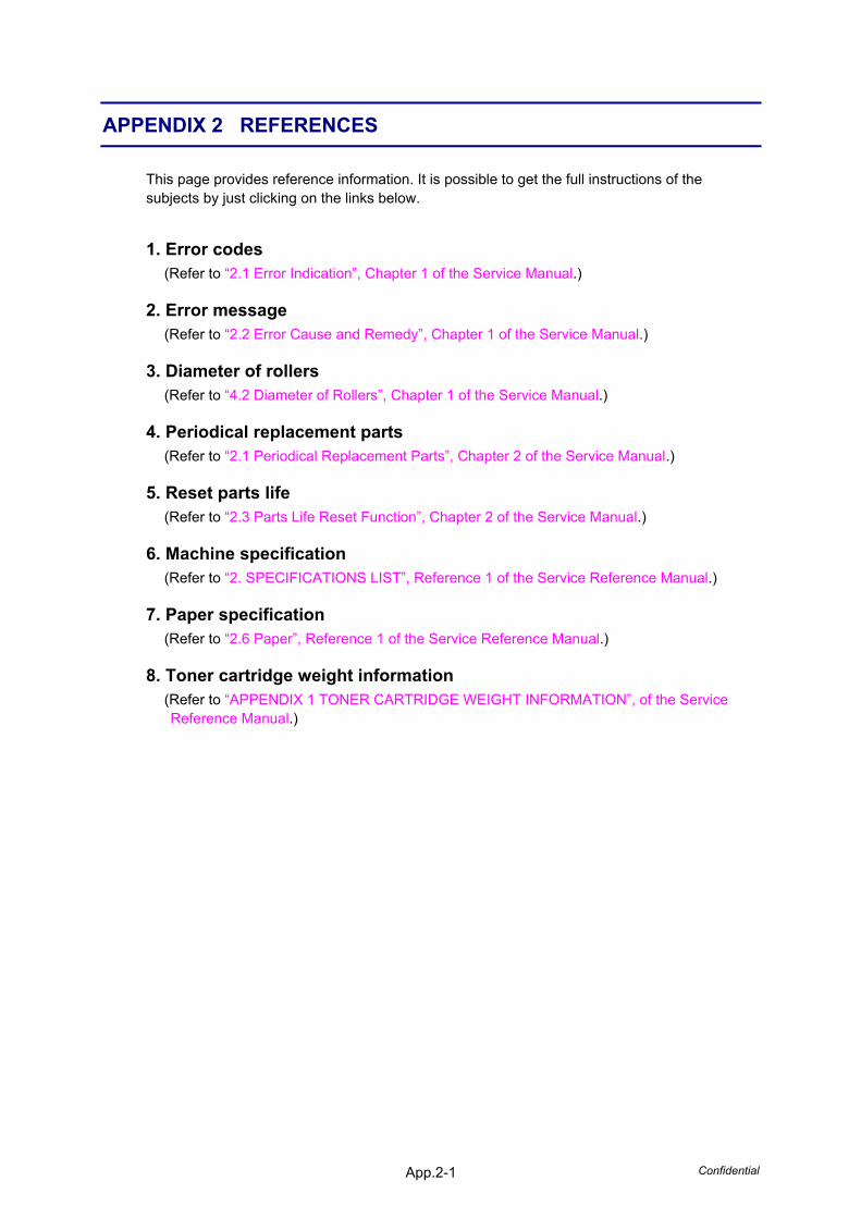
APPENDIX 2 REFERENCES
This page provides reference information. It is possible to get the full instructions of the subjects by just clicking on the links below.
1. Error codes (Refer to “2.1 Error Indication”, Chapter 1 of the Service Manual.)
2. Error message (Refer to “2.2 Error Cause and Remedy”, Chapter 1 of the Service Manual.)
3. Diameter of rollers (Refer to “4.2 Diameter of Rollers”, Chapter 1 of the Service Manual.)
4. Periodical replacement parts (Refer to “2.1 Periodical Replacement Parts”, Chapter 2 of the Service Manual.)
5. Reset parts life (Refer to “2.3 Parts Life Reset Function”, Chapter 2 of the Service Manual.)
6. Machine specification (Refer to “2. SPECIFICATIONS LIST”, Reference 1 of the Service Reference Manual.)
7. Paper specification (Refer to “2.6 Paper”, Reference 1 of the Service Reference Manual.)
8. Toner cartridge weight information (Refer to “APPENDIX 1 TONER CARTRIDGE WEIGHT INFORMATION”, of the Service Reference Manual.)
Confidential App.3-1
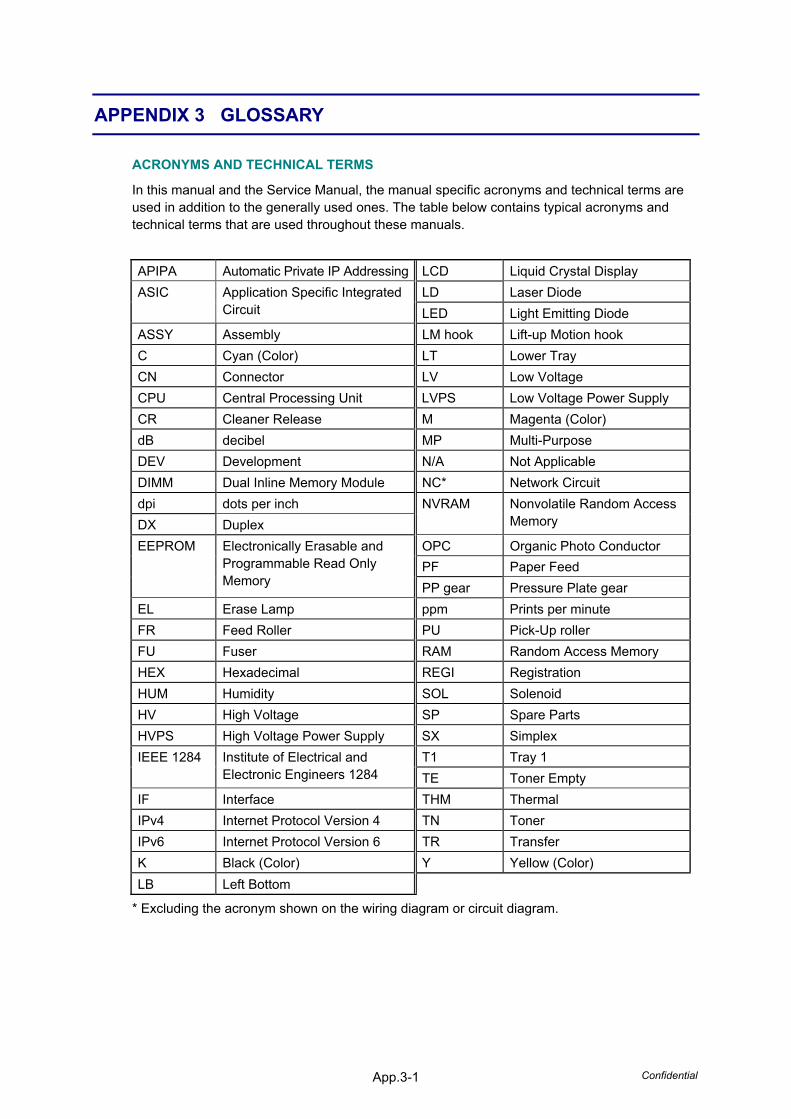
APPENDIX 3 GLOSSARY
ACRONYMS AND TECHNICAL TERMS
In this manual and the Service Manual, the manual specific acronyms and technical terms are used in addition to the generally used ones. The table below contains typical acronyms and technical terms that are used throughout these manuals.
APIPA Automatic Private IP Addressing LCD Liquid Crystal Display LD Laser Diode ASIC Application Specific Integrated
Circuit LED Light Emitting Diode ASSY Assembly LM hook Lift-up Motion hook C Cyan (Color) LT Lower Tray CN Connector LV Low Voltage CPU Central Processing Unit LVPS Low Voltage Power Supply CR Cleaner Release M Magenta (Color) dB decibel MP Multi-Purpose DEV Development N/A Not Applicable DIMM Dual Inline Memory Module NC* Network Circuit dpi dots per inch DX Duplex
NVRAM Nonvolatile Random Access Memory
OPC Organic Photo Conductor PF Paper Feed
EEPROM Electronically Erasable and Programmable Read Only Memory PP gear Pressure Plate gear
EL Erase Lamp ppm Prints per minute FR Feed Roller PU Pick-Up roller FU Fuser RAM Random Access Memory HEX Hexadecimal REGI Registration HUM Humidity SOL Solenoid HV High Voltage SP Spare Parts HVPS High Voltage Power Supply SX Simplex
T1 Tray 1 IEEE 1284 Institute of Electrical and Electronic Engineers 1284 TE Toner Empty
IF Interface THM Thermal IPv4 Internet Protocol Version 4 TN Toner IPv6 Internet Protocol Version 6 TR Transfer K Black (Color) Y Yellow (Color) LB Left Bottom
* Excluding the acronym shown on the wiring diagram or circuit diagram.