+ All Categories
Home > Documents > 8080-4D, Computer Testing Supplement for Aviation Mechanic General, Powerplant… · 2011-08-14 ·...

8080-4D, Computer Testing Supplement for Aviation Mechanic General, Powerplant… · 2011-08-14 ·...

Date post: 04-Jul-2018
Category:
Upload: trinhcong
View: 219 times
Download: 0 times
Share this document with a friend
79
U.S. Department of Transportation Federal Aviation Administration FAA-CT-8080-4E DO NOT MARK IN THIS BOOK COMPUTER TESTING SUPPLEMENT FOR AVIATION MECHANIC GENERAL, POWERPLANT, AND AIRFRAME; AND PARACHUTE RIGGER
Transcript

U.S. Department of TransportationFederal Aviation Administration

FAA-CT-8080-4E

DO NOT MARK IN THIS BOOK

COMPUTER TESTING SUPPLEMENTFOR

AVIATION MECHANIC GENERAL,POWERPLANT, AND AIRFRAME;

AND PARACHUTE RIGGER

CT-8080-4E_Cover 04/20/2005, 1:59 PM1

COMPUTER TESTING SUPPLEMENTFOR

AVIATION MECHANIC GENERAL,POWERPLANT, AND AIRFRAME;

AND PARACHUTE RIGGER

2005

U.S. DEPARTMENT OF TRANSPORTATION

FEDERAL AVIATION ADMINISTRATIONFlight Standards Service

CT-8080-4E FrontPages 04/13/2005, 1:30 PM1

CT-8080-4E FrontPages 04/13/2005, 1:30 PM2

PREFACE

This computer testing supplement is designed by the Flight Standards Service of the Federal Aviation Administration(FAA) for use by computer testing designees (CTDs) in the administration of computer-assisted airman knowledge testsin the following knowledge areas:

Aviation Mechanic General—AMGAviation Mechanic Powerplant—AMPAviation Mechanic Airframe—AMAParachute Rigger—RIG, RMC, RMP

FAA-CT-8080-4E supersedes FAA-CT-8080-4D, Computer Testing Supplement for Aviation Mechanic General,Powerplant, and Airframe; and Parachute Rigger, dated 2001.

Comments regarding this supplement should be sent to:

U.S. Department of TransportationFederal Aviation AdministrationFlight Standards ServiceAirman Testing Standards Branch, AFS-630P.O. Box 25082Oklahoma City, OK 73125

iii

CT-8080-4E FrontPages 04/13/2005, 1:30 PM3

CT-8080-4E FrontPages 04/13/2005, 1:30 PM4

FIGURE 1.—Equation ............................................................................................................................................ 1FIGURE 2.—Equation ............................................................................................................................................ 1FIGURE 3.—Equation ............................................................................................................................................ 1FIGURE 4.—Circuit Diagram ................................................................................................................................ 2FIGURE 5.—Formula ............................................................................................................................................. 2FIGURE 6.—Circuit Diagram ................................................................................................................................ 2FIGURE 7.—Circuit Diagram ................................................................................................................................ 3FIGURE 8.—Circuit Diagram ................................................................................................................................ 3FIGURE 9.—Circuit Diagram ................................................................................................................................ 3FIGURE 10.—Battery Circuit ................................................................................................................................ 4FIGURE 11.—Circuit Diagram .............................................................................................................................. 4FIGURE 12.—Circuit Diagram .............................................................................................................................. 4FIGURE 13.—Circuit Diagram .............................................................................................................................. 5FIGURE 14.—Circuit Diagram .............................................................................................................................. 5FIGURE 15.—Landing Gear Circuit ...................................................................................................................... 6FIGURE 16.—Fuel System Circuit ........................................................................................................................ 7FIGURE 17.—Electrical Symbols .......................................................................................................................... 8FIGURE 18.—Landing Gear Circuit ...................................................................................................................... 9FIGURE 19.—Landing Gear Circuit ...................................................................................................................... 9FIGURE 20.—Circuit Diagram ............................................................................................................................ 10FIGURE 21.—Electrical Symbols ........................................................................................................................ 10FIGURE 22.—Transistors ..................................................................................................................................... 11FIGURE 23.—Transistorized Circuit ................................................................................................................... 12FIGURE 24.—Logic Gate .................................................................................................................................... 13FIGURE 25.—Logic Gate .................................................................................................................................... 13FIGURE 26.—Logic Gates ................................................................................................................................... 14FIGURE 27.—Object Views ................................................................................................................................. 15FIGURE 28.—Object Views ................................................................................................................................. 15FIGURE 29.—Object Views ................................................................................................................................. 16FIGURE 30.—Object Views ................................................................................................................................. 16FIGURE 31.—Sketches ........................................................................................................................................ 17FIGURE 32.—Sketches ........................................................................................................................................ 18FIGURE 33.—Material Symbols .......................................................................................................................... 18FIGURE 34.—Aircraft Drawing ........................................................................................................................... 19FIGURE 35.—Aircraft Drawing ........................................................................................................................... 20FIGURE 36.—Aircraft Drawing ........................................................................................................................... 21FIGURE 37.—Aircraft Drawing ........................................................................................................................... 22FIGURE 38.—Performance Chart ........................................................................................................................ 22FIGURE 39.—Electric Wire Chart ....................................................................................................................... 23FIGURE 40.—Cable Tension Chart ...................................................................................................................... 23FIGURE 41.—Performance Chart ........................................................................................................................ 24FIGURE 42.—Aircraft Hardware ......................................................................................................................... 24FIGURE 43.—Aircraft Hardware ......................................................................................................................... 25

Preface ................................................................................................................................................................ iiiContents ............................................................................................................................................................... v
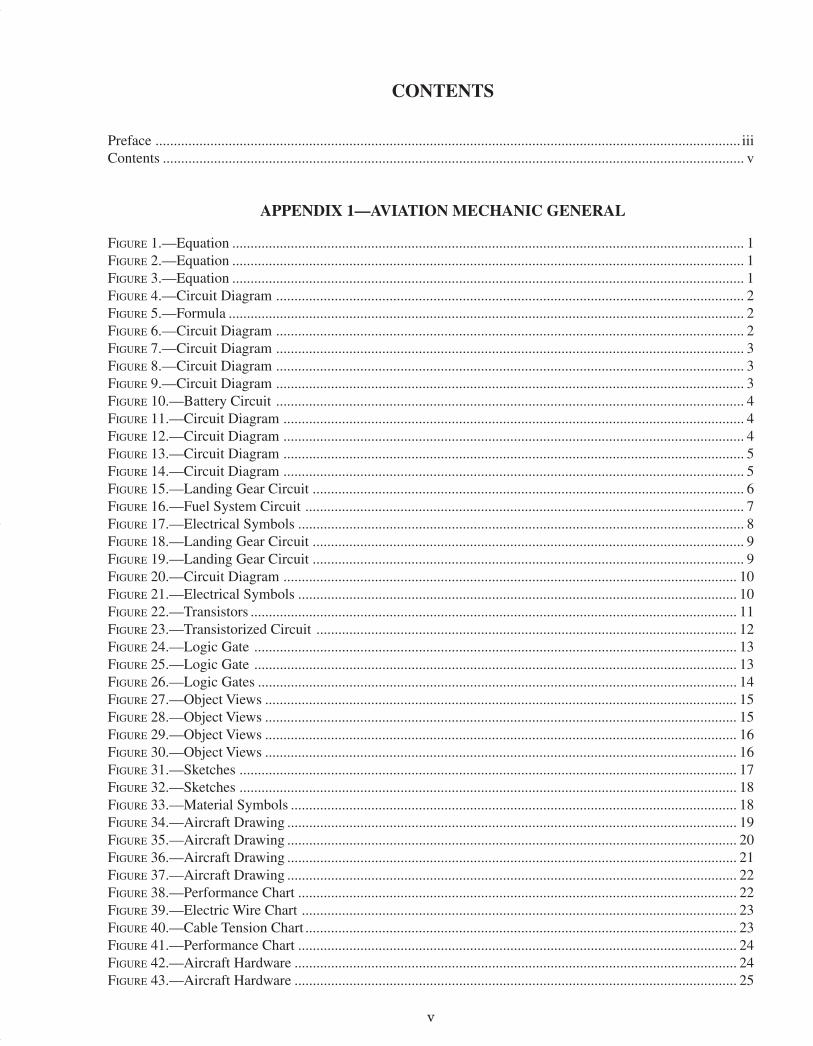
CONTENTS

APPENDIX 1—AVIATION MECHANIC GENERAL

v

CT-8080-4E FrontPages 04/13/2005, 1:30 PM5

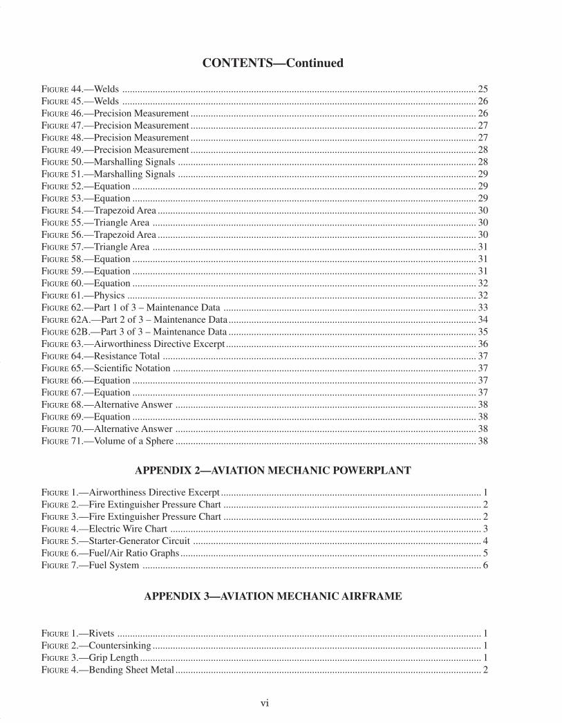
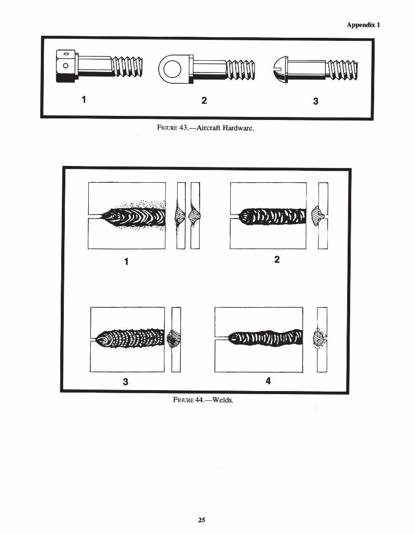
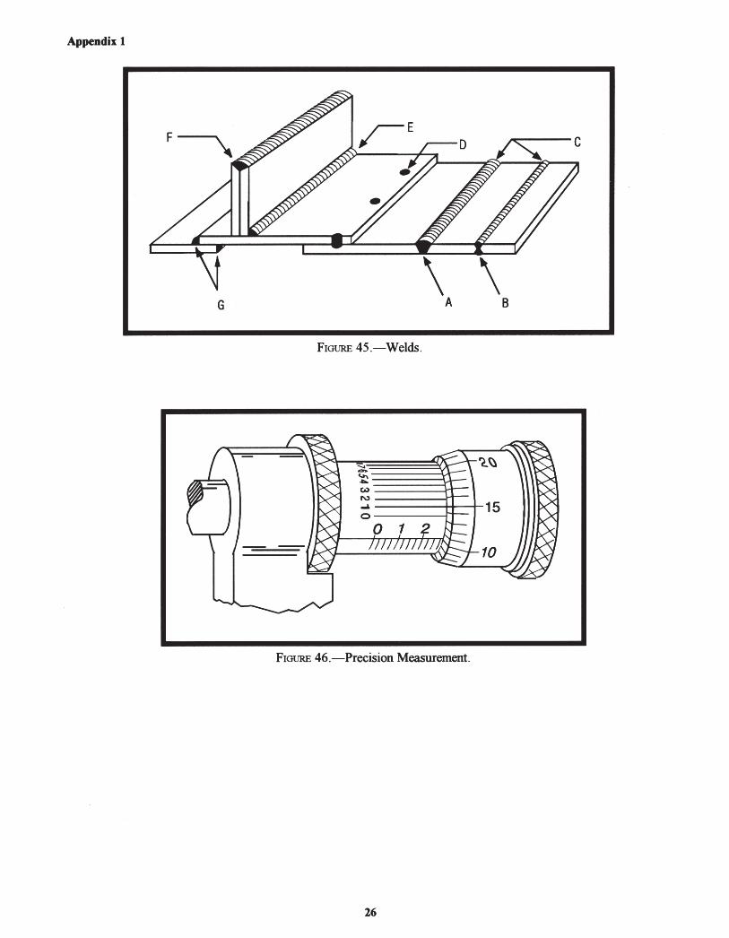
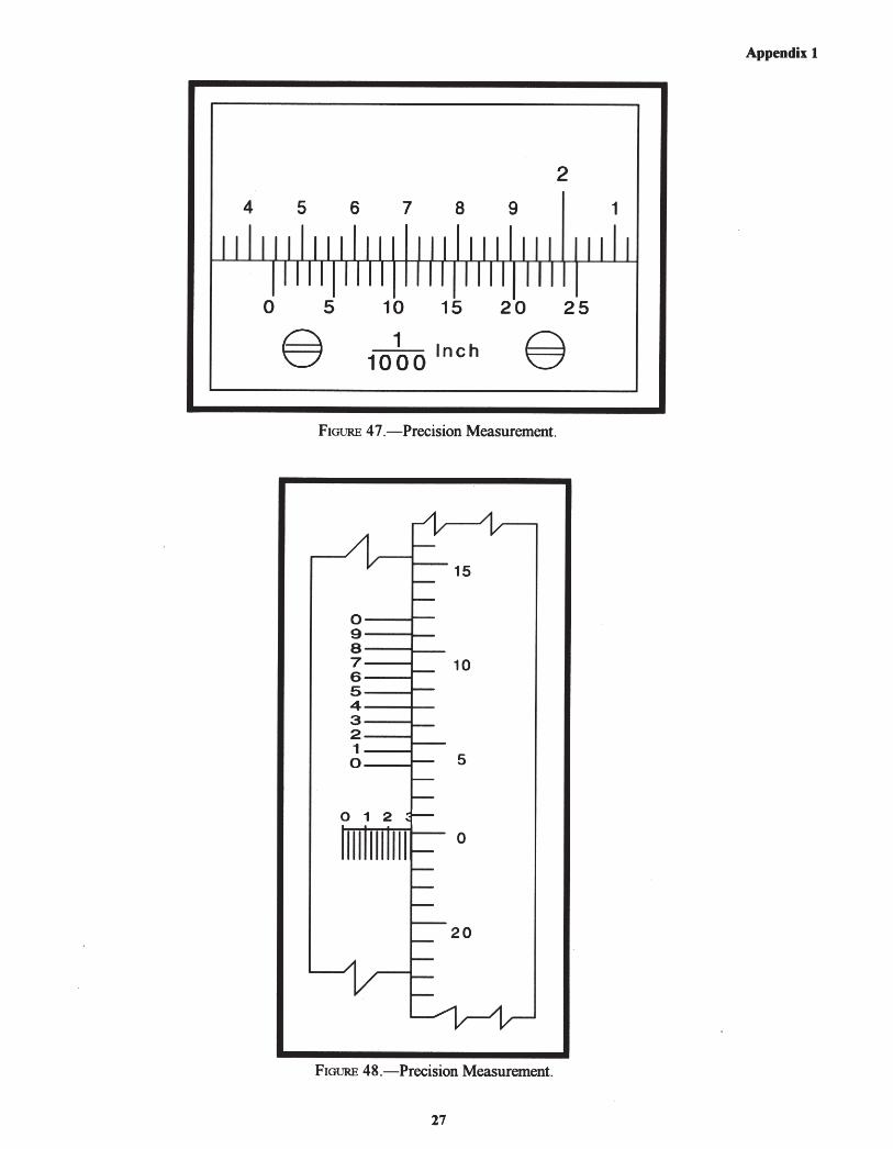
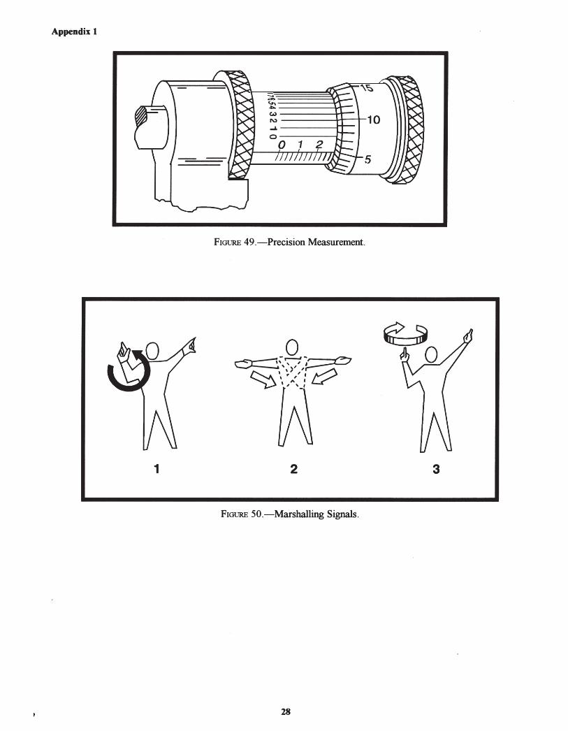
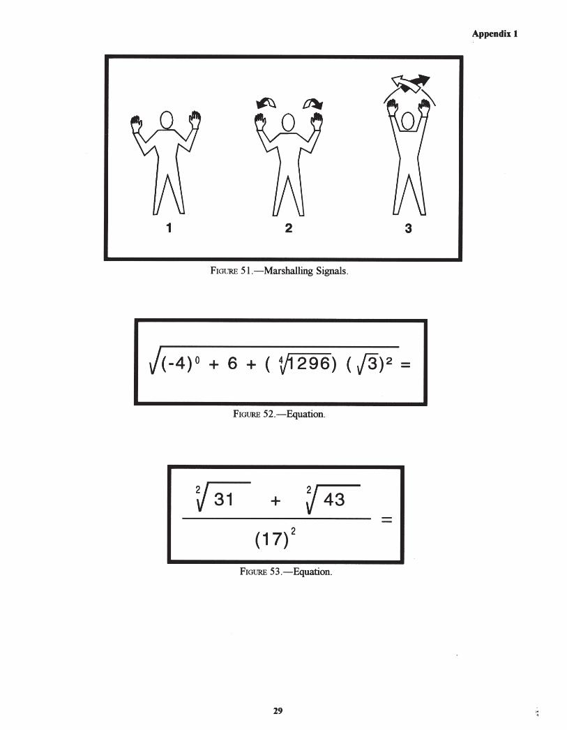
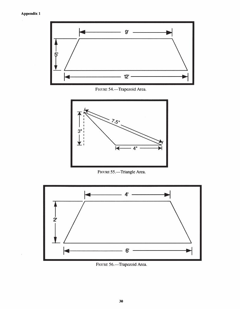
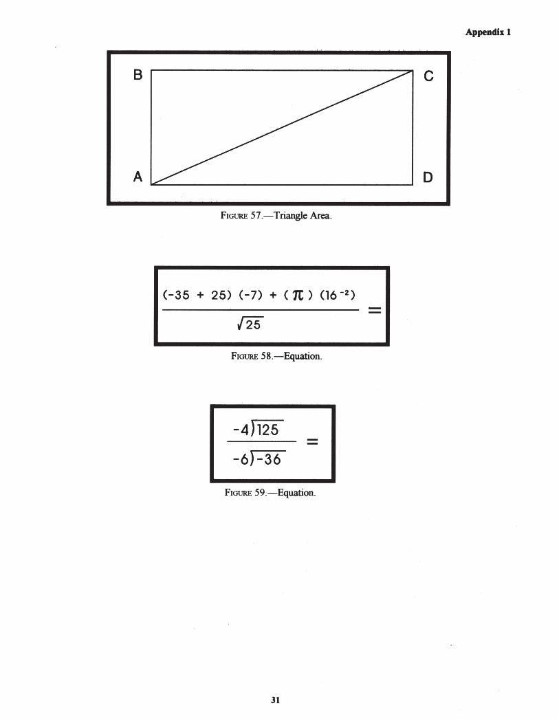
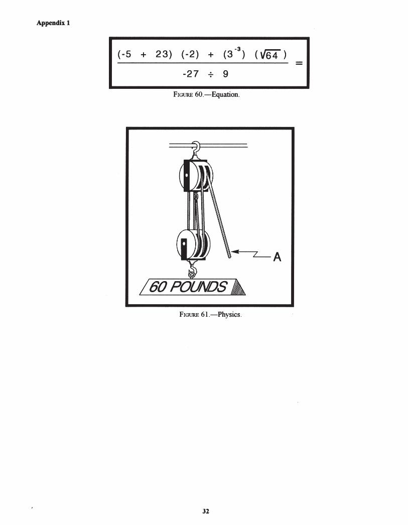
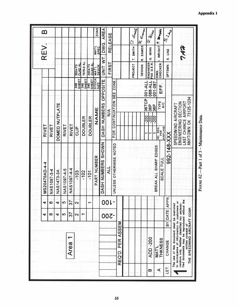
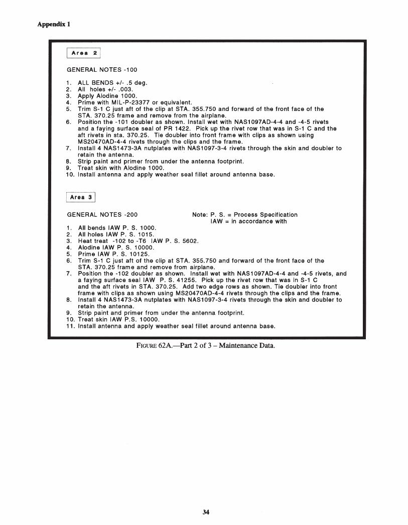
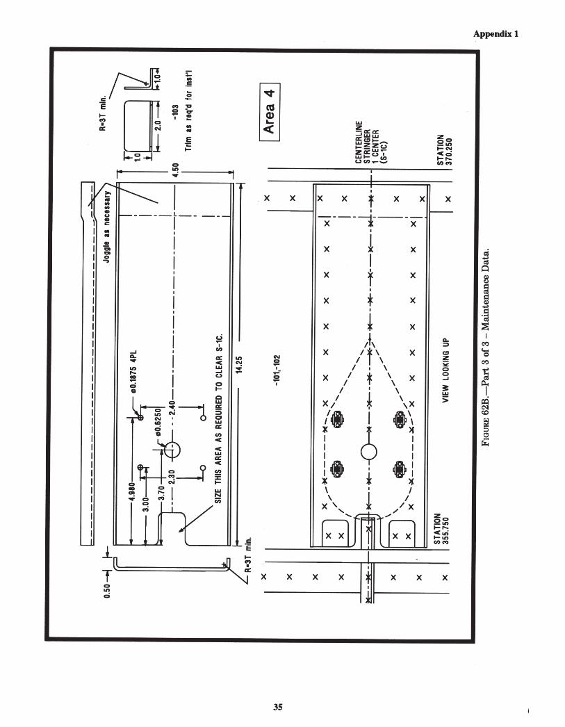
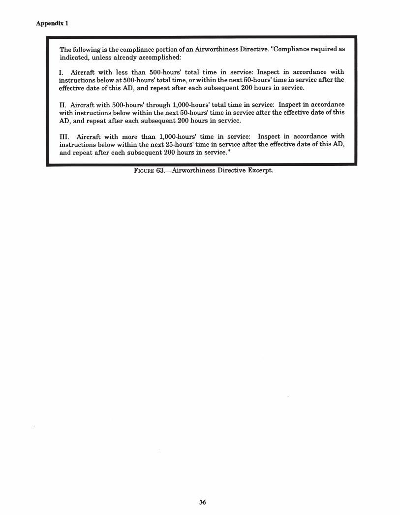
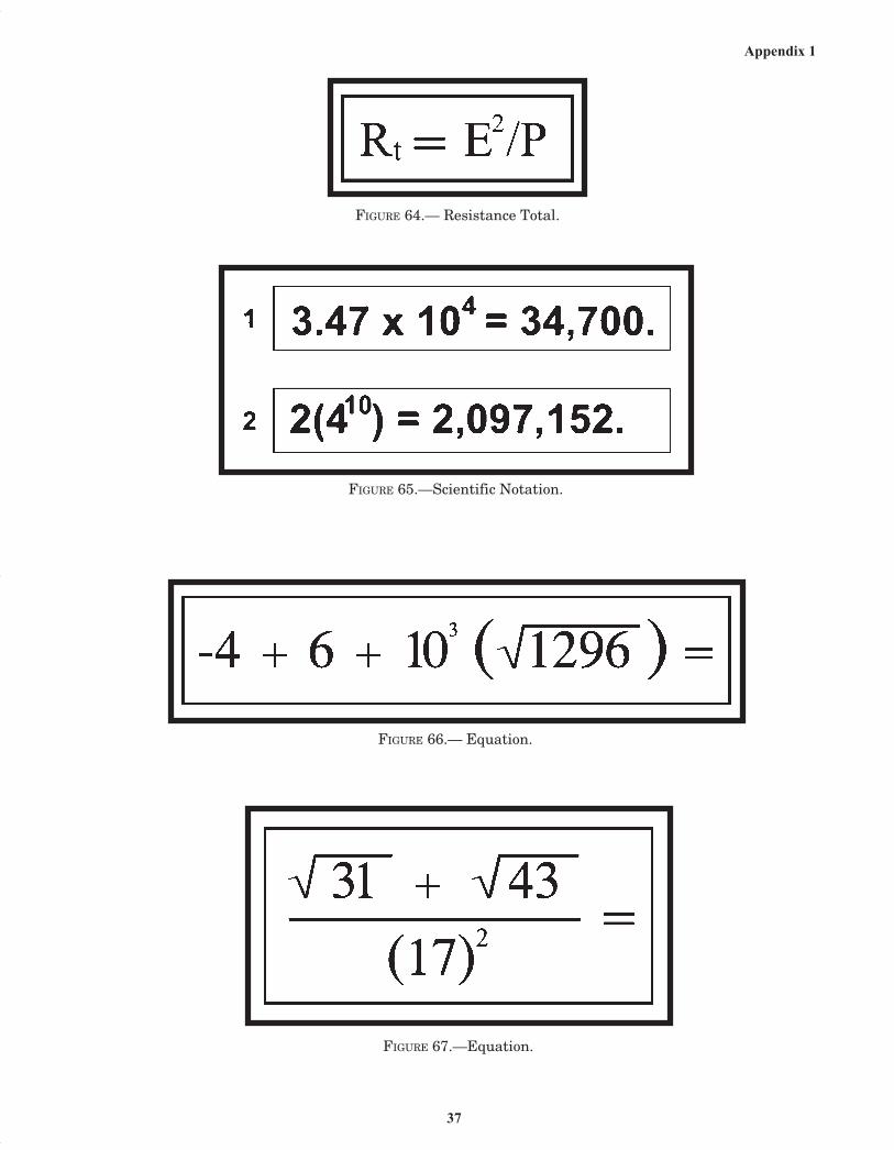
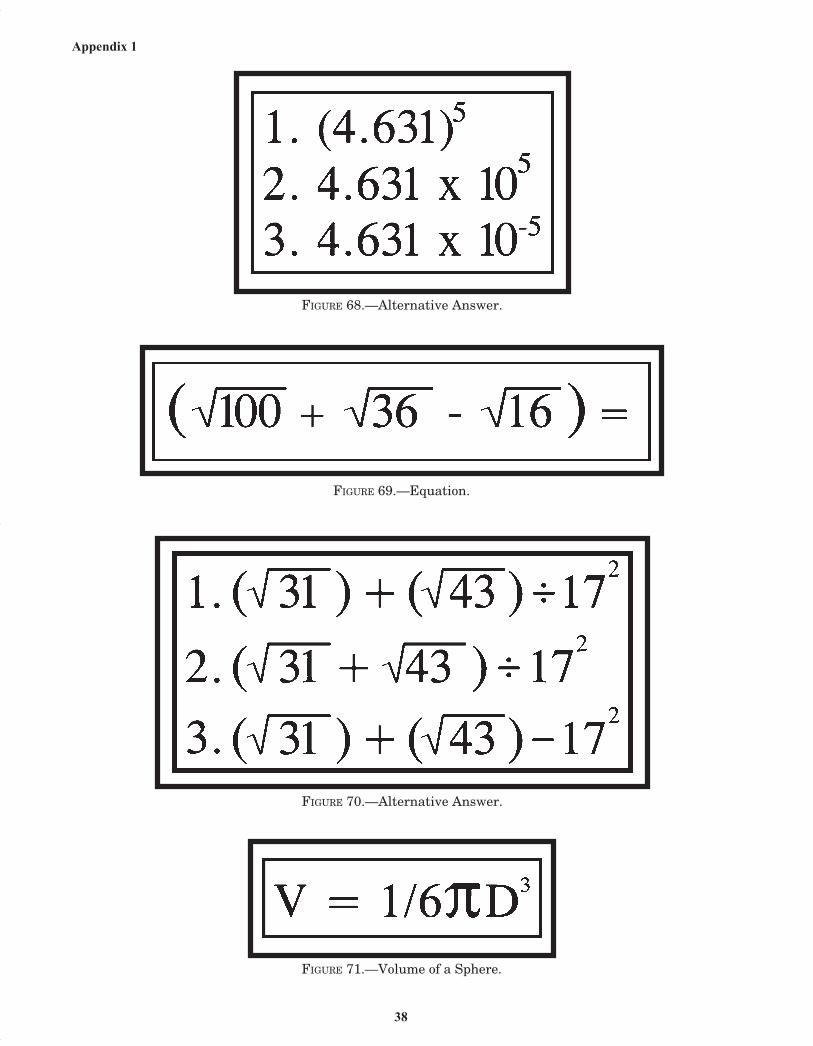
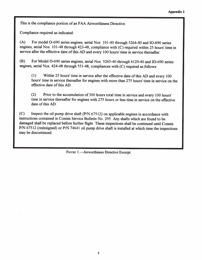
FIGURE 44.—Welds ............................................................................................................................................ 25FIGURE 45.—Welds ............................................................................................................................................ 26FIGURE 46.—Precision Measurement ................................................................................................................. 26FIGURE 47.—Precision Measurement ................................................................................................................. 27FIGURE 48.—Precision Measurement ................................................................................................................. 27FIGURE 49.—Precision Measurement ................................................................................................................. 28FIGURE 50.—Marshalling Signals ...................................................................................................................... 28FIGURE 51.—Marshalling Signals ...................................................................................................................... 29FIGURE 52.—Equation ........................................................................................................................................ 29FIGURE 53.—Equation ........................................................................................................................................ 29FIGURE 54.—Trapezoid Area .............................................................................................................................. 30FIGURE 55.—Triangle Area ................................................................................................................................ 30FIGURE 56.—Trapezoid Area .............................................................................................................................. 30FIGURE 57.—Triangle Area ................................................................................................................................ 31FIGURE 58.—Equation ........................................................................................................................................ 31FIGURE 59.—Equation ........................................................................................................................................ 31FIGURE 60.—Equation ........................................................................................................................................ 32FIGURE 61.—Physics .......................................................................................................................................... 32FIGURE 62.—Part 1 of 3 – Maintenance Data .................................................................................................... 33FIGURE 62A.—Part 2 of 3 – Maintenance Data .................................................................................................. 34FIGURE 62B.—Part 3 of 3 – Maintenance Data .................................................................................................. 35FIGURE 63.—Airworthiness Directive Excerpt ................................................................................................... 36FIGURE 64.—Resistance Total ............................................................................................................................ 37FIGURE 65.—Scientific Notation ........................................................................................................................ 37FIGURE 66.—Equation ........................................................................................................................................ 37FIGURE 67.—Equation ........................................................................................................................................ 37FIGURE 68.—Alternative Answer ....................................................................................................................... 38FIGURE 69.—Equation ........................................................................................................................................ 38FIGURE 70.—Alternative Answer ....................................................................................................................... 38FIGURE 71.—Volume of a Sphere ....................................................................................................................... 38

FIGURE 1.—Rivets ................................................................................................................................................ 1FIGURE 2.—Countersinking .................................................................................................................................. 1FIGURE 3.—Grip Length ....................................................................................................................................... 1FIGURE 4.—Bending Sheet Metal ......................................................................................................................... 2

CONTENTS—Continued

APPENDIX 3—AVIATION MECHANIC AIRFRAME

vi

FIGURE 1.—Airworthiness Directive Excerpt ....................................................................................................... 1FIGURE 2.—Fire Extinguisher Pressure Chart ...................................................................................................... 2FIGURE 3.—Fire Extinguisher Pressure Chart ...................................................................................................... 2FIGURE 4.—Electric Wire Chart ........................................................................................................................... 3FIGURE 5.—Starter-Generator Circuit .................................................................................................................. 4FIGURE 6.—Fuel/Air Ratio Graphs ....................................................................................................................... 5FIGURE 7.—Fuel System ...................................................................................................................................... 6

APPENDIX 2—AVIATION MECHANIC POWERPLANT

CT-8080-4E FrontPages 04/13/2005, 1:30 PM6

FIGURE 1.—Tacking Knot ..................................................................................................................................... 1FIGURE 2.—Parachute Material ............................................................................................................................ 1FIGURE 3.—Seam Stitching .................................................................................................................................. 2FIGURE 4.—Suspension Line Attachment ............................................................................................................ 2FIGURE 5.—Suspension Lines .............................................................................................................................. 3FIGURE 6.—Fittings .............................................................................................................................................. 3FIGURE 7.—Radial Seam Stitching ....................................................................................................................... 4FIGURE 8.—Lift Web Stitching ............................................................................................................................. 4FIGURE 9.—Knots ................................................................................................................................................. 5FIGURE 10.—Machine Stitching ........................................................................................................................... 5FIGURE 11.—French Fell Seam ............................................................................................................................ 6FIGURE 12.—English Fell Seam ........................................................................................................................... 6FIGURE 13.—Machine Stitching ........................................................................................................................... 7FIGURE 14.—Machine Stitching ........................................................................................................................... 7FIGURE 15.—Machine Stitching ........................................................................................................................... 7FIGURE 16.—Hardware Threading ....................................................................................................................... 8

APPENDIX 4—PARACHUTE RIGGER

CONTENTS—Continued

vii

FIGURE 5.—Sheet Metal Layout ........................................................................................................................... 2FIGURE 6.—Sheet Metal Layout ........................................................................................................................... 3FIGURE 7.—Sheet Metal Layout ........................................................................................................................... 3FIGURE 8.—Control Cable .................................................................................................................................... 4FIGURE 9.—Cable Tension Chart .......................................................................................................................... 4FIGURE 10.—Torque Value ................................................................................................................................... 5FIGURE 11.—Fittings ............................................................................................................................................ 5FIGURE 12.—Backup Rings .................................................................................................................................. 5FIGURE 13.—Cooling System ............................................................................................................................... 6FIGURE 14.—Pressure Temperature Correction Chart .......................................................................................... 6FIGURE 15.—Formula ........................................................................................................................................... 7FIGURE 16.—Antennas ......................................................................................................................................... 7FIGURE 17.—Fuel System .................................................................................................................................... 7FIGURE 18.—Battery Connections ........................................................................................................................ 8FIGURE 19.—Landing Gear Circuit ...................................................................................................................... 9FIGURE 20.—Landing Gear Circuit .................................................................................................................... 10FIGURE 21.—Fire Extinguisher Chart ................................................................................................................. 10

CT-8080-4E FrontPages 04/13/2005, 1:30 PM7

ASA_8080 4D 6/2/04 11:18 AM Page 9 (Black plate)

ASA_8080 4D 6/2/04 11:18 AM Page 10 (Black plate)

ASA_8080 4D 6/2/04 11:19 AM Page 11 (Black plate)

ASA_8080 4D 6/2/04 11:19 AM Page 12 (Black plate)

ASA_8080 4D 6/2/04 11:19 AM Page 13 (Black plate)

ASA_8080 4D 6/2/04 11:20 AM Page 14 (Black plate)

ASA_8080 4D 6/2/04 11:20 AM Page 15 (Black plate)

ASA_8080 4D 6/2/04 11:20 AM Page 16 (Black plate)

ASA_8080 4D 6/2/04 11:21 AM Page 17 (Black plate)

ASA_8080 4D 6/2/04 11:21 AM Page 18 (Black plate)

ASA_8080 4D 6/2/04 11:21 AM Page 19 (Black plate)

ASA_8080 4D 6/2/04 11:21 AM Page 20 (Black plate)

ASA_8080 4D 6/2/04 11:22 AM Page 21 (Black plate)

ASA_8080 4D 6/2/04 11:22 AM Page 22 (Black plate)

ASA_8080 4D 6/2/04 11:22 AM Page 23 (Black plate)

ASA_8080 4D 6/2/04 11:22 AM Page 24 (Black plate)

ASA_8080 4D 6/2/04 11:23 AM Page 25 (Black plate)

ASA_8080 4D 6/2/04 11:23 AM Page 26 (Black plate)

ASA_8080 4D 6/2/04 11:23 AM Page 27 (Black plate)

ASA_8080 4D 6/2/04 11:23 AM Page 28 (Black plate)

ASA_8080 4D 6/2/04 11:23 AM Page 29 (Black plate)

ASA_8080 4D 6/2/04 11:24 AM Page 30 (Black plate)

ASA_8080 4D 6/2/04 11:24 AM Page 31 (Black plate)

ASA_8080 4D 6/2/04 11:24 AM Page 32 (Black plate)

ASA_8080 4D 6/2/04 11:24 AM Page 33 (Black plate)

ASA_8080 4D 6/2/04 11:25 AM Page 34 (Black plate)

ASA_8080 4D 6/2/04 11:25 AM Page 35 (Black plate)

ASA_8080 4D 6/2/04 11:25 AM Page 36 (Black plate)

ASA_8080 4D 6/2/04 11:25 AM Page 37 (Black plate)

ASA_8080 4D 6/2/04 11:25 AM Page 38 (Black plate)

ASA_8080 4D 6/2/04 11:26 AM Page 39 (Black plate)

ASA_8080 4D 6/2/04 11:26 AM Page 40 (Black plate)

ASA_8080 4D 6/2/04 11:26 AM Page 41 (Black plate)

ASA_8080 4D 6/2/04 11:26 AM Page 42 (Black plate)

ASA_8080 4D 6/2/04 11:26 AM Page 43 (Black plate)

ASA_8080 4D 6/2/04 11:26 AM Page 44 (Black plate)

ASA_8080 4D 6/2/04 11:27 AM Page 45 (Black plate)

ASA_8080 4D 6/2/04 11:27 AM Page 46 (Black plate)

Appendix 1

37

FIGURE 64.— Resistance Total.

FIGURE 65.—Scientific Notation.

FIGURE 66.— Equation.

FIGURE 67.—Equation.

Appen1_pages37-38 04/13/2005, 12:28 PM37

Appendix 1

38

FIGURE 68.—Alternative Answer.

FIGURE 69.—Equation.

FIGURE 70.—Alternative Answer.

FIGURE 71.—Volume of a Sphere.

Appen1_pages37-38 04/13/2005, 12:28 PM38

ASA_8080 4D 6/2/04 11:27 AM Page 47 (Black plate)

ASA_8080 4D 6/2/04 11:27 AM Page 49 (Black plate)

ASA_8080 4D 6/2/04 11:27 AM Page 50 (Black plate)

ASA_8080 4D 6/2/04 11:27 AM Page 51 (Black plate)

Appendix 2

4

FIGURE 5.—Starter-Generator Circuit.

Appen2_page4_2 04/13/2005, 12:34 PM4

ASA_8080 4D 6/2/04 11:28 AM Page 53 (Black plate)

ASA_8080 4D 6/2/04 11:28 AM Page 54 (Black plate)

ASA_8080 4D 6/2/04 11:28 AM Page 55 (Black plate)

ASA_8080 4D 6/2/04 11:29 AM Page 57 (Black plate)

ASA_8080 4D 6/2/04 11:29 AM Page 58 (Black plate)

ASA_8080 4D 6/2/04 11:29 AM Page 59 (Black plate)

ASA_8080 4D 6/2/04 11:29 AM Page 60 (Black plate)

ASA_8080 4D 6/2/04 11:29 AM Page 61 (Black plate)

ASA_8080 4D 6/2/04 11:30 AM Page 62 (Black plate)

ASA_8080 4D 6/2/04 11:30 AM Page 63 (Black plate)

ASA_8080 4D 6/2/04 11:30 AM Page 64 (Black plate)

ASA_8080 4D 6/2/04 11:30 AM Page 65 (Black plate)

ASA_8080 4D 6/2/04 11:31 AM Page 66 (Black plate)

ASA_8080 4D 6/2/04 11:31 AM Page 67 (Black plate)

ASA_8080 4D 6/2/04 11:31 AM Page 69 (Black plate)

ASA_8080 4D 6/2/04 11:31 AM Page 70 (Black plate)

ASA_8080 4D 6/2/04 11:31 AM Page 71 (Black plate)

ASA_8080 4D 6/2/04 11:32 AM Page 72 (Black plate)

ASA_8080 4D 6/2/04 11:32 AM Page 73 (Black plate)

ASA_8080 4D 6/2/04 11:32 AM Page 74 (Black plate)

ASA_8080 4D 6/2/04 11:32 AM Page 75 (Black plate)

ASA_8080 4D 6/2/04 11:33 AM Page 76 (Black plate)


Recommended