+ All Categories
Home > Documents > A Comparison of Various Strategies for Direct

A Comparison of Various Strategies for Direct

Date post: 06-Apr-2018
Category:
Upload: mohamed-nabil
View: 218 times
Download: 0 times
Share this document with a friend
6
 A Comparison of Various Strategies for Direct Torque Control of Induction Motors Lamia YOUB , Aurelian CRACIUNESCU POLITEHNICA University of Bucharest, Electrical Engineering Faculty, 313, Splaiul Independentei, 060042 Bucharest, Romania, [email protected]  Abstract - In this paper three new direct torque control strategies are compared with the classical direct torque control scheme. The consi dered new strategies are the following: direct torque control strategy with fuzzy logic regulators instead of hysteresis regulators, direct torque control strategy with hysteresis regulators associated with fuzzy logic regulators, and direct torque control strategy with fuzzy, hysteresis and space vector modulation respectively. A comparison analysis among the classical direct torque control strategy and the new ones, made by simulation in MATLAB/SIMULINK, a given.  Keywords  — Induction machine, Direct torque control Fuzzy logic. I. I  NTRODUCTION In applications of high-performance induction motor drives such as motion control, it is usually desirable that the motor can provide good dynamic torque response as is obtained from dc motor drives. Many control schemes have been proposed for this goal, among which the vector control or sometimes called field oriented control has been recognized as one of the most effective methods [1, 2, 3]. It is well known that vector control needs quite complicated coordinate transforms on line to decouple the interaction between flux control and torque control to provide fast torque control of induction motor. Hence the algorithm computation is time consuming and its implementation usually requires using a high  performance DSP chip. In recent years an innovative control method called direct torque control (DTC) has gained the attraction of researchers, because it can also  produce fast torque control of the induction motor and does not need heavy computation on-line, in contrast to vector control. Basically direct torque control employs two hysteresis controllers to regulate stator flux and developed torque respectively, to obtain approximately decoupling of the flux and torque control. The key issue of design of the DTC is the strategy of how to select the proper stator voltage vector to force stator flux and developed torque into their prescribed band. The hysteresis controller is usually a two-value bang-bang controller, which results in taking the same action for the big torque error and small torque error. Thus it may produce big torque ripple. In order to improve the performance of the DTC it is natural to divide torque error into several intervals, on which different control action is; taken. As the DTC control strategy is not based on mathematical analysi s, it is not easy to give an apparent boundary to the division of torque error. Fuzzy control is a way for controlling a system without the need of knowing the plant mathematic model. It uses the experience of  people's knowledge to form its control rule base. There have appeared many applications of fuzzy control on power electronic and motion control in the past few years [9, 10]. A fuzzy logic controller was reported being used with DTC [7]. However there arises the problem that the rule numbers it used is too many which would affect the speed of the fuzzy reasoning. In this paper a comparison of various strategy of direct torque control of induction motors is used to improve the performance of DTC scheme. The control algorithm is based on the SVM technique to provide a constant inverter switching frequency and reduced flux and torque ripple and current distortion. A space vector is generated by two fuzzy logic controllers associated with hysteresis regulators. The first one is to control flux and the other to control torque. The use of fuzzy controllers permits a faster response and more robustness. II. DIRECT TORQUE CONTROL PRINCIPLE The basic functional blocks used to implement the DTC scheme are represented in Figure 1. The instantaneous values of the stator flux and torque are calculated from stator variable by using a closed loop estimator [1]. Stator flux and torque can be controlled directly and independently by properly selecting the inverter switching configuration. This method is based on maintaining the amplitude and the phase of the stator current constants, avoiding electromagneti c transients It 1-4244-0891-1/07/$20.00 ©2007 IEEE
Transcript

8/3/2019 A Comparison of Various Strategies for Direct

http://slidepdf.com/reader/full/a-comparison-of-various-strategies-for-direct 1/6

A Comparison of Various Strategies for Direct

Torque Control of Induction Motors

Lamia YOUB , Aurelian CRACIUNESCU

POLITEHNICA University of Bucharest, Electrical Engineering Faculty,

313, Splaiul Independentei, 060042 Bucharest, Romania,

[email protected]

Abstract - In this paper three new direct torque control

strategies are compared with the classical direct torque

control scheme. The considered new strategies are the

following: direct torque control strategy with fuzzy logic

regulators instead of hysteresis regulators, direct torque

control strategy with hysteresis regulators associated with

fuzzy logic regulators, and direct torque control strategy

with fuzzy, hysteresis and space vector modulationrespectively. A comparison analysis among the classical

direct torque control strategy and the new ones, made by

simulation in MATLAB/SIMULINK, a given.

Keywords — Induction machine, Direct torque control

Fuzzy logic.

I. I NTRODUCTION

In applications of high-performance induction motor

drives such as motion control, it is usually desirable that

the motor can provide good dynamic torque response as

is obtained from dc motor drives. Many control schemeshave been proposed for this goal, among which the

vector control or sometimes called field oriented control

has been recognized as one of the most effective

methods [1, 2, 3]. It is well known that vector control

needs quite complicated coordinate transforms on line todecouple the interaction between flux control and torque

control to provide fast torque control of induction motor.

Hence the algorithm computation is time consuming andits implementation usually requires using a high

performance DSP chip. In recent years an innovative

control method called direct torque control (DTC) has

gained the attraction of researchers, because it can also

produce fast torque control of the induction motor anddoes not need heavy computation on-line, in contrast to

vector control.

Basically direct torque control employs two hysteresiscontrollers to regulate stator flux and developed torque

respectively, to obtain approximately decoupling of the

flux and torque control. The key issue of design of the

DTC is the strategy of how to select the proper stator

voltage vector to force stator flux and developed torqueinto their prescribed band. The hysteresis controller is

usually a two-value bang-bang controller, which results

in taking the same action for the big torque error and

small torque error. Thus it may produce big torqueripple. In order to improve the performance of the DTC

it is natural to divide torque error into several intervals,

on which different control action is; taken. As the DTC

control strategy is not based on mathematical analysis, itis not easy to give an apparent boundary to the division

of torque error. Fuzzy control is a way for controlling a

system without the need of knowing the plant

mathematic model. It uses the experience of people'sknowledge to form its control rule base. There have

appeared many applications of fuzzy control on power

electronic and motion control in the past few years [9,10]. A fuzzy logic controller was reported being used

with DTC [7]. However there arises the problem that the

rule numbers it used is too many which would affect the

speed of the fuzzy reasoning. In this paper a comparison

of various strategy of direct torque control of induction

motors is used to improve the performance of DTCscheme. The control algorithm is based on the SVM

technique to provide a constant inverter switching

frequency and reduced flux and torque ripple and

current distortion. A space vector is generated by twofuzzy logic controllers associated with hysteresis

regulators. The first one is to control flux and the other

to control torque. The use of fuzzy controllers permits afaster response and more robustness.

II. DIRECT TORQUE CONTROL PRINCIPLE

The basic functional blocks used to implement the

DTC scheme are represented in Figure 1. The

instantaneous values of the stator flux and torque arecalculated from stator variable by using a closed loop

estimator [1]. Stator flux and torque can be controlled

directly and independently by properly selecting theinverter switching configuration. This method is based

on maintaining the amplitude and the phase of the stator

current constants, avoiding electromagnetic transients It

1-4244-0891-1/07/$20.00©2007 IEEE

8/3/2019 A Comparison of Various Strategies for Direct

http://slidepdf.com/reader/full/a-comparison-of-various-strategies-for-direct 2/6

is possible to control directly the stator flux and torque by selecting the appropriate inverter state [1], [5].

An induction machine can be modeled with stator current and flux in reference ( α , β ) as state variable bythe following equations

..

.. sV B X A X +=

Where:

,.

.

⎥⎥⎥

⎢⎢⎢

⎡=

s

is

X

φ

⎥⎦

⎤⎢⎣

⎡=

s

si X

φ (1)

⎥⎥⎥⎥

⎢⎢⎢⎢

+−

−−

−−+

σ

σ

σ

σ

σ

σ

σ

.1

.

1

.

1

.

1

.

jT T

M

M j

M T L

R

A

r r

r r

s

(2)

⎥⎥

⎢⎢

⎡=

00

.

1

..

1

σ σ r r s L L L B (3)

⎥⎦

⎤⎢⎣

⎡ −=

01

10 j ,

s

s s

R

LT = ,

r

r r

R

LT = (4)

The induction stator flux and torque are given by:

( )dt i Rv s s s s ∫ −=φ (5)

( )α β β α φ φ s s s se ii pT −= . (6)

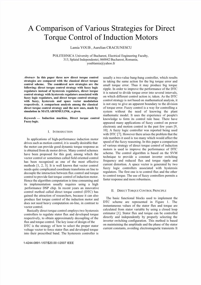
The estimated values of the stator flux and torqueare compared to their command values Φ sref,, T ref respectively. Switching states are selected according to

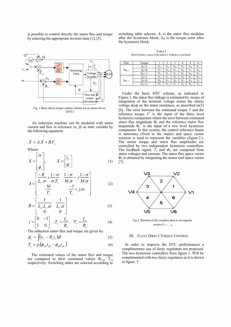
switching table selector. S T is the stator flux modulusafter the hysteresis block; S Ф is the torque error after the hysteresis block.

TABLE I

SWITCHING TABLE FOR DIRECT TORQUE CONTROL

Under the basic DTC scheme, as indicated inFigure.1, the stator flux linkage is estimated by means of integration of the terminal voltage minus the ohmicvoltage drop on the stator resistance, as described in(5)

[6]. The error between the estimated torque T and the

reference torque T *

is the input of the three levelhysteresis comparator where the error between estimatedstator flux magnitude Φs and the reference stator fluxmagnitude Φs

* is the input of a two level hysteresiscomparator. In this system, the control reference frameis stationary (fixed to the stator) and space vector notation is used to represent the variables (figure.2.).The motor torque and stator flux amplitudes arecontrolled by two independent hysteresis controllers.The feedback signal, T e and Φr , are computed fromstator voltages and currents. The stator flux space vector Φs is obtained by integrating the motor emf space vector [7]:

III. FUZZY DIRECT TORQUE CONTROL

In order to improve the DTC performances a

complimentary use of fuzzy regulators are proposed.

The two hysteresis controllers from figure 1. Will becomplimented with two fuzzy regulators as it is shown

in figure. 3

Fig. 1 Basic direct torque control scheme for ac motor drives

(DTC)

Fig.2. Partition of the complex plan in six angular

sectors S I = 1… 6

8/3/2019 A Comparison of Various Strategies for Direct

http://slidepdf.com/reader/full/a-comparison-of-various-strategies-for-direct 3/6

It follows from the previous section that thecontroller adopting DTC strategy has the property of

hysteresis, which only takes two value controls for the

very big or small error of the torque. That means thecontrol action will be the same in the whole error range.To get better control performance a fuzzy logic

controller has been introduced to be a compliment to the

hysteresis controller . The wide of hysteresis cycle will

be fuzzy variables: φ b for flux controller andT

b for

torque controller. The fuzzy controller design is based

on intuition and simulation. These values compose a

training set which is used to obtain the table of rules

where is given the dependence φ bΔ (e1, e2) and

T bΔ (e1, e2), where e1 and e2 are the inputs. The fuzzy

rules sets are shown in Table 2. In Fig. 3 it is shown themembership functions of input and output variables. The

rules were formulated using analysis data obtained from

the simulation of the system using different values of torque hysteresis band.

PH: positive high, NH: negative high,

PM: positive medium, NM: negative medium,

PS: positive small, NS: negative small, ZE: zero

The linguistic rules can be expressed by the following

example:• If (e1 is NH or NM and e2 is N) then ( Δ bΓ or Δ bφ is

N):This case corresponds to a big overshoot in torque

error, consequently high torque ripple. To reduce thetorque ripple, the value Δ bΓ should be reduced [3]. In

this case, the overshoot in torque error can touch theupper band which will cause a reverse voltage vector to

be selected. This one will result in a torque to be

reduced rapidly and causes undershoot in the torqueresponse below the hysteresis band. Thus, Δ bΓ should

not be too small; Δ bΓ is set Positive in order to avoid this

situation.

TABLE. 2

FUZZY RULES OF TORQUE AND FLUX HYSTERESIS CONTROLLER

Fig. 3 The improvement of DTC performances by adding fuzzy

controllers

Fig. 5 Control surface

8/3/2019 A Comparison of Various Strategies for Direct

http://slidepdf.com/reader/full/a-comparison-of-various-strategies-for-direct 4/6

IV. SPACE VECTOR MODULATION

The aim of SVM is to minimize harmonic distortion

in the current by selecting the appropriate switching

vectors and determining their corresponding dwelling

widths [5]. As depicted in Fig. 6 there are eight statesavailable for voltage space vector according to eight

switching positions of the inverter. SVM is based on

time averaging techniques during sampling period T s. If the reference vector V s (V ref = V 1 + V 2 ), is located in

sector I (Fig.6), then it is composed of voltage vector V 1

and V 2 and zero vectors V 0 and V 7, one finds [6]:

All techniques SVM use to synthesize the reference

voltage standard the following equations:

( )21702

1T T T T T s −−== (4)

( )

⎟ ⎠

⎞⎜⎝

−=

3sin

sin

21

π

θ π a

T T s (5)

Several strategies SVM can be used for the piloting of

the inverter only difference between these strategies is

the choice of the null vector and the sequence of

application of the vectors tension during the period of sampling.

22111 V T V T VsT += (6)

( )

⎞⎜

⎛ =

3

sin

sin

21

π

θ a

T T s (7)

Where: T 1 and T 2 are the active pulse times of voltage vectorsV 1 and V 2.

⎟⎟ ⎠

⎞⎜⎜⎝

⎛ =

dc

s

V

V a

3

2

V dc : d-c link voltage. T 0, T 7 are a null vector times.

IV. SIMULATION RESULTS

To study the performance of the fuzzy logic controller

with direct torque control strategy, the simulation of the

system was conducted by using MATLAB /SIMULINK and fuzzy logic. The problem of how to make the flux

rapidly reaching its given value when system started

with direct torque control was experienced. From figure

(8) one can see that torque response in steady state is

very rapid especially during the starting stage due to theflux being controlled within its rated value before torque

reaching its given value. This control strategy can provide full torque while the motor is at a standstill. In

steady state the torque is quite stable. Figure (8, 9, 10,and 11) shows a comparison between the DTC classic

and DTC with fuzzy regulators, DTFC- hysteresis and

DTFC-SVM. The comparison of the steady state behavior obtained using the basic switching table and

the proposed DTFC. The machine is running at 100

rad/sec. Fig. (9) and Fig. (10) shows an appreciable

reduction of current, flux and torque ripple has beenobtained using fuzzy regulators associated with

hysteresis regulators. These results are obtained in spite

of using larger sampling period for the DTFC. The

simulation results given in Fig. (11) show a goodtracking of electromagnetic torque using DTFC -SVM

and prove that this technique allow a good dynamic

performance similar to the basic DTC schemes. Also itcan be noted that the effects due to the crossing of sector

boundaries, typical of basic DTC schemes, are avoided

using the DTFC-hysteresis scheme.

Fig. 6 Decomposition of voltage vector

8/3/2019 A Comparison of Various Strategies for Direct

http://slidepdf.com/reader/full/a-comparison-of-various-strategies-for-direct 5/6

Fig. 11 Response of a.4) trajectory of flux, b.4) electromagnetic

torque and c.4) stator current for scheme of DTC

DTC- fuzzy hysteresis with SVM

Fig.9. Simulation results of DTC with fuzzy regulators of induction motors, a.2) Stator flux trajectory , b.2)

Electromagnetic torque, c.2) Stator currentFig.8. Simulation results of Classical DTC of induction motor

a.1) Stator flux trajectory b.1) Electromagnetic torque c.1) Stator

current

Fig. 10. a.3) Response of trajectory of flux,b.3) electromagnetic

c.3)torque and stator current for scheme of DTC

Simulation results of DTC -fuzzy hysteresis regulators associated

8/3/2019 A Comparison of Various Strategies for Direct

http://slidepdf.com/reader/full/a-comparison-of-various-strategies-for-direct 6/6

VI. CONCLUSION

In this paper the following strategies of direct torque

control of induction motors are compared with classical

DTC strategy : direct torque control strategy with fuzzylogic regulators instead of hysteresis regulators, direct

torque control strategy with hysteresis regulatorsassociated with fuzzy logic regulators, and direct torque

control strategy with fuzzy, hysteresis and space vector

modulation.

It is shown that in the case of direct torque controlstrategy with fuzzy regulators instead of hysteresis

regulators the magnetic flux and the torque ripples are

smaller as in DTC classical strategy but the currentamplitude is bigger. In the case of DTC strategy with

hysteresis regulators associated with fuzzy logic

regulators the performances are better: the magnetic

flux, the torque ripples and the current amplitude aresmaller as in DTC classical strategy. The similar results

have been obtained also in the case of direct torque

control strategy with fuzzy, hysteresis and space vector

modulation associated.

R EFERENCE

[1] Casadei, D., serra, G., Tani, A, «Performance Analysis of a

DTC Control Scheme for Induction Motor in the Low SpeedRange», in proceeding of EPE, (1997), p.3.700-3.704,

Trondheim.

[2] Depenbrok. M, «Direct self-control (DSC) of Inverter FedInduction Machine», In: IEEE Trans. On PE (1988), Vol. PE-3,

No4, October 1988, p 420-429.[3] Youb, L, Craciunescu, A, «Study on Fuzzy Control of Induction

Motors with Direct Torque Control», the 4 th Internationnal

Conference on Computer, Electrical, and Systems Science, and

Engineering, Prague, Republic Czech, July 27-29, 2007 (Paper Accepted).

[4] Ned Gulley, J.-S. Roger Jang: «Fuzzy Logic Toolbox for Use

With Matlab ». The Math Works inc, Natick, Mass, 1996.

[5] H.Buhler: «Réglage par Logique floue ». Presses polytechniques

et universitaires Romande, 1994.[6] Sayeed Mir, Malik E. Elbuluk, Donald S. Zinger: «PI and fuzzy

Estimators for Tuning the Stator Resistance in Direct Torque

Control of Induction Machines ». IEEE Trans. On Power Electronics, Vol. 13, No. 2, pp. 279-287, March 1998.

APPENDIX

I NDUCTION MOTOR PARAMETRS

Power rating 4 kWStator voltage 220/380 V

Stator resistance 10 Ω

Stator leakage inductance 0.6550 H

Rotor resistance 6.3 Ω

Rotor leakage inductance 0.6520 H

Mutual inductance 0.612 HInertia 0.03kg.m2

Number of poles 2

Torque rating 25 N.m


Recommended