Abstract—In order to fully study small wind turbines (WTs), acomprehensive model that considers all mechanical and electricalaspects is necessary. The permanent magnet synchronous genera-tor (PMSG)-based WT is one of the most common types of WTsthat uses a full scale converter with a variable speed WT. In thispaper, a new model is developed for a PMSG-based WT with yawcontrol scheme. The WT generator is connected to a grid by twoback-to-back voltage source IGBT converters and a dc capacitor setbetween them. A precise mechanical model is necessary to simulateyaw control. The yaw control is used as a mechanical mechanism toadjust yaw error and protect small horizontal axis wind turbines(HAWT) against over speed and excess power. TurbSim and FASTare used to model a wind profile and the mechanical parts of theWT. Also, the WT generator and electrical controllers are modeledby Simulink. Field oriented control (FOC) method is developed onthe voltage source converters (VSCs). Simulation results show theperformance of the mechanical and electrical controllers in differ-ent conditions.
Index Terms—FAST, field oriented control (FOC), permanentmagnet synchronous generator (PMSG) wind turbine, TurbSim,Yaw control.
I. INTRODUCTION
W IND energy application, as an economic type of renew-able energy, is growing in recent years. With increasing
oil price, security threats, and environmental concerns, the por-tion of wind energy is expected to be 12% of total global energyby 2020 [1]. The WT extracted power depends on wind velocityand WT structure. The variable speed WTs, the most commontype of the wind energy conversion systems (WECS), are ableto extract more power than the fixed speed WTs.
The WT with PMSG is an efficient configuration for variablespeed WTs. The advantages of this configuration include theelimination of dc excitation, less repair requirement, and highpower to weight ratio. To connect the WT to the network, afull-scale converter is utilized providing a wide operation rangefor rotation speed and captured power.
Different methods can be used to implement maximum powerpoint tracking (MPPT) in variable speed WTs [2]. The WT
Manuscript received January 25, 2013; revised April 23, 2013 and August 7,2013; accepted September 4, 2013. Paper no. TEC-00040-2013.
H. Shariatpanah and R. Fadaeinedjad are with the Department of Electricaland Computer Engineering, Graduate University of Advanced Technology,Kerman 76315-117, Iran (e-mail: [email protected];[email protected]).
M. Rashidinejad is with the Department of Electrical Engineering,Shahid Bahonar University of Kerman, Kerman 76169-133, Iran (e-mail:[email protected]).
Color versions of one or more of the figures in this paper are available onlineat http://ieeexplore.ieee.org.
Digital Object Identifier 10.1109/TEC.2013.2281814
controllers can be implemented using adaptive [3], fuzzy [4],robust [5], and gain scheduling [6] control techniques. In [7],a new vector control is used for PMSG WT based on directcurrent vector control. The WT controller also can improve thenetwork stability [8].
The modern WTs should be able to stay connected to the gridduring and after grid faults that cause more mechanical stress onthe WT structure. The development of the complete electrome-chanical model is required to study this type of event and canhelp to evaluate performance of controllers in different condi-tions. In [9], a precise model has been presented for a doublyfed induction generator WT using FAST (fatigue, aerodynam-ics, structures, and turbulence) and Simulink. No publicationthat authors are aware of has proposed models for the PMSGWT and controllers using FAST.
The main contribution of the paper is to develop a comprehen-sive model for a WT considering all electrical, mechanical, andaerodynamic aspects simultaneously. Also, the proposed modeluses the new method to suppress and control the WT excessiveoutput power at high wind speed using yaw mechanism. Thedesigned yaw controller uses gain scheduling method in differ-ent control areas. Basically, the yaw controller task is to keepthe rotor faced the wind but we defined a new task for yaw con-troller to control the excess power in high wind speed withoutadding a new hardware (e.g., pitch mechanism or furl mecha-nism). It should be mentioned that the yaw motion may causelarge forces on the structure in large WTs. With this respect, thepitch mechanism is usually used in large WTs to control gener-ated power. In small WTs, however, yaw motion can be used tocontrol WT in high wind speed. The yaw motion is sometimescreated by furling mechanism in small WTs. In this paper, how-ever, an active yaw mechanism is used. This method cannot beused for large scale WTs, because the enormous gyroscopic andwind loads may cause problem on the WT structure during yawmotion.
In this paper, a new model is developed for a 10 kW PMSGWT, using different software including TurbSim, FAST, andSimulink. A 3-D turbulent wind profile is produced by Turbsim.The mechanical parts of turbine and generator are modeled byFAST considering many important mechanical motions in theWT. Unlike conventional WTs that use pitch and stall controlto limit extracted power, this WT uses yaw control to limitcaptured power. This controller rotates the WT nacelle aheadof the wind and the effective area of the WT rotor is reduced,therefore, the WT output power is controlled. The electricalparts are modeled by Simulink. The generator is connected tothe network through two VSCs. The overall structure of themodel is given in Section II. The control scheme is presented
This article has been accepted for inclusion in a future issue of this journal. Content is final as presented, with the exception of pagination.
2 IEEE TRANSACTIONS ON ENERGY CONVERSION
Fig. 1. Overall structure of simulated system.
in Section III, where the network side converter (NSC) and thegenerator side converter (GSC) controllers are described. Theelectrical controllers are designed in d − q frame based on FOC.The power signal feedback (PSF), used to implement MPPT,is also explained. The performance of the WT controllers hasbeen studied using two wind profile types as will be explainedin Section IV.
II. SYSTEM MODELING DESCRIPTION
The simulation structure of the WT system is shown in Fig. 1.As can be seen in this figure, the system consists of differentcomponents including: WT, PMSG, VSC, and controllers. TheWT captures the wind energy that is converted to the electricityby PMSG with variable frequency. The generated voltages arerectified by a rectifier and an inverter transfers the generatedpower to the network through a filter at network frequency. Thesimulated components are described in the following sections.
A. Wind Generation and Wind Turbine Model
In this paper, the wind profile has been generated byTurbSim [10]. TurbSim is a stochastic, full field, turbulent windsimulator, and produces time series of wind velocity vectorswith the desired accuracy for each point of the area swept bythe blades. To produce wind, this software requires some infor-mation of the wind and environmental conditions such as hubheight, wind turbulence intensity, altitude, and average windspeed. In this paper, TurbSim is used to produce a 12 × 12points grid wind with turbulence intensity of “A” class and theaverage speed value of 14 m/s (at 37 m hub height). This outputwind data is used by FAST software [11].
FAST and automatic dynamic analysis of mechanical sys-tems (ADAMS) are complex mechanical software that can beused to model the HAWTs. A modal approach in combina-
tion with Kane dynamics is used by FAST code to develop theequations of motion. The Kane method is used to obtain the dy-namic equations for multibody systems comprehensively and ef-ficiently [12]. ADAMS provides multibody dynamic simulation,automatically formulates the mechanical model, and solves theequations of motions with high accuracy [13]. Against ADAMSthat includes more details of the WT motion, less time is neededto run FAST because it uses the modal approach with fewer de-grees of freedoms (DOFs) to describe the most important partsof turbine dynamics. Different types of WT can be modeled byFAST such as up and down wind, two and three bladed, pitchand stall controlled. Some of these models are built based onreal models such as Bergey Excel-S/60 WT with 10 kW ratedpower. FAST has been used to simulate the mechanical partsof the WT, whereby AeroDyn [14] has been used to model theaerodynamic forces.
The aerodynamic forces for each point of the blade are cal-culated by AreoDyn subcode. AreoDyn considers the effects ofthe blade deflection and velocities on blade aerodynamic forces.This subcode requires some input data files such as wind pro-file, airfoil lift, and drag coefficients. AreoDyn input files arecreated by some preprocessor software (i.e., FoilCheck and Air-foilPrep). The programs TurbSim, AeroDyn, and FAST havebeen developed at the National Renewable Energy Laboratory(NREL), Golden, CO, USA, and they are free for all [11].
As the WT equations are modeled in the dynamic form, itis possible to examine interactions between the mechanical andthe electrical systems. Dynamic equations consider all of theforces on WT such as aerodynamic forces on the blades andgravity forces. For HAWT with three blades, FAST is able toconsider 24 DOFs.
In this paper, FAST has been used to model an upwind, three-bladed rotor HAWT with a rigid hub and foundation consider-ing DOFs including the first and second flapwise blade modes,
This article has been accepted for inclusion in a future issue of this journal. Content is final as presented, with the exception of pagination.
SHARIATPANAH et al.: NEW MODEL FOR PMSG-BASED WIND TURBINE WITH YAW CONTROL 3
edgewise mode, yaw angle, and generator azimuth angle. Theyaw control technique, as the power control method, is used insmall WTs to limit captured power at high-speed wind condi-tions. The yaw controller adjusts yaw error on zero to capturemaximum power from wind below WT rated wind speed. Aboverated wind speed, this controller permits rotating of nacelle, ro-tor, and drive train around the yawing portion of the structureon top of the tower to reduce effective rotor area and limit inputpower.
B. PMSG Model
The PMSG is modeled by below equations using Park trans-formation. These equations are based on stator current and volt-ages as follows:
vsd = Rsid +dλd
dt− ωeλq (1)
vsq = Rsiq +dλq
dt+ ωeλd (2)
where vsq and vsd are stator voltages, id and iq are stator currentsin d − q reference frame, and Rs is resistance of stator winding.The stator flux can be defined as follows:
λd = Lsdid + λm , λq = Lsq iq (3)
where λm is core magnetic flux and Lsd , Lsq are the d − qinductances of the stator winding. The PMSG electrical torqueis obtained by the following equation:
Te =32p[λm iq − (Lsq − Lsd)iq id ] (4)
where p is the PMSG pole pairs. The PMSG type is consideredsurface mounted magnet, therefore Lsd and Lsq are equal andthe electrical torque and power are given as
Te =32p(λm iq ) (5)
Pe = ωm Te (6)
ωm = ωe/p. (7)
C. Voltage Source Converter
In Fig. 1, the VSC is composed of two back-to-back threephase IGBT bridges, each consisting of six switches. In thispaper, the switch dynamics have not been considered in thesimulation, where a special FOC is used to control each bridgethat is explained in the following section.
III. CONTROLLER SCHEME
The WT controllers consist of two main parts including themechanical controller and the electrical controller. The NSCand GSC are controlled by the electrical controller, where themechanical controller is used to limit captured power at highwind speed.
The electrical controller, composing of NSC controller andGSC controller, are designed using d − q variables. This designmethod provides independent control parameters and simpledesign compared to other methods such as phase and angle
Fig. 2. Network-side converter control scheme.
method [15]. The NSC controller can control the dc link voltageand the reactive power injection to the network (or PCC busvoltage). The NSC controller can provide the reactive power tothe network, even the wind is not blowing. The WT cannot pro-duce active power with no wind. The NSC, however, can injectreactive power to the network similar to a static synchronouscompensator (STATCOM).
The generator active power, extracted from wind, is controlledby GSC controller. This controller makes the WT working athighest efficiency, where the set point of the generator shaftspeed is determined by the MPPT. The speed set point is calcu-lated based on the generator output power and WT parameters,when the WT is operating below rated wind speed. The calcula-tion of the speed set point is sometimes summarized as look uptable of ω − P curve. The electrical controller cannot control(limit) the output power when the WT is operating above ratedwind speed.
The mechanical controller limits the WT input power in highwind speed utilizing yaw control method. The yaw controllersets yaw angle and its actuator horizontally rotates the WT rotor.The effective rotor area is reduced by rotating rotor ahead of thewind.
A. NSC Control
The NSC controller is implemented based on the networkcurrent d − q components, as shown in Fig. 2. It consists of twocontrol loops that control the dc link voltage and the reactivepower independently. The first loop includes two cascade loopsthat control dc link voltage Vdc and the d-component of thenetwork current id . The inner control loop regulates id about areference value i∗d that is determined by outer control loop. Tofollow signal variation, the inner loop should be faster than theouter loop. The reactive power is regulated at zero to reach unitypower factor by the second loop.
The NSC model, shown in Fig. 3, is implemented using thefollowing equations:
vd = −(
Rf id + Lfdiddt
)+ ωnLf iq + vnd (8)
vq = −(
Rf iq + Lfdiqdt
)− ωnLf id + vnq (9)
This article has been accepted for inclusion in a future issue of this journal. Content is final as presented, with the exception of pagination.
4 IEEE TRANSACTIONS ON ENERGY CONVERSION
Fig. 3. Network-side converter model.
where Rf and Lf are the filter resistance and inductance. vnd,q ,vd,q , and id,q are the d − q components of the PCC voltage, theVSC output voltage, and the network current, respectively. ωn
is the network angular frequency that is calculated by a phaselocked loop (PLL). Inner loop (current loop) is designed basedon (8) and (9). The controller output voltage signals are obtainedby the following equations:
md =2
Vdc(−v′
d + ωnLf iq + vnd) (10)
mq =2
Vdc(−v′
q − ωnLf id + vnq ) (11)
where v′d and v′
q are the d − q components of the uncompen-sated voltage that are generated by the NSC current controllers.The NSC controller includes three standard PI with Franklinantiwind up model [16]. Equation (12) shows the PI transferfunction
G(s) = Kp +Kp
Tis(12)
where Kp and Ti are the controller parameters. The inner loopPI parameters can be obtained from the following relations [17]:
Kp =L
2Ts, Ti =
L
R,R = Rf + Rn
L = Lf + Ln , Ts =3
fswitching(13)
where Rn and Ln are the network resistance and inductance.To design outer loop controller, dc link should be modeled by
dynamic equation. This equation is nonlinear and dependent onmany parameters as follows:
dV 2dc
dt=
2C
Pt −2C
Ploss −1C
[2Pn +
(4LPn
3V 2nd
)dPn
dt
]
+1C
(4LQn
3V 2nd
)dQn
dt(14)
where Pt , Pn , and Ploss are the WT output active power, theactive power delivered to the network, and the power loss. Qn
is the delivered reactive power to the network and C is thecapacitance of the dc link. Equation (14) can be simplified as(15)
dVdc
dt=
1CVdc
Pt −1
CVdcPn . (15)
In (15), the dc link voltage will remain constant if the WToutput power and the delivered power to the network are equal.
Fig. 4. Generator-side converter control scheme.
Fig. 5. Generator-side converter model.
The following relationships can be used to adjust the parametersof the PI controller [18]
Kpdc =C
4Ts, Tidc = 8Ts. (16)
B. GSC Control
The generator side control scheme is shown in Fig. 4. Thecontroller, consisting of two control loops, are designed basedon the d − q components of the generator stator current. Thesetwo control loops work independently. The first loop adjusts d-component of stator current i∗sd . The controller usually controlsi∗sd at zero to reach unity power factor, decreasing the powerloss and stator current. The second control loop includes twocascade loops (outer and inner loops), where outer loop regulatesthe shaft speed to maximize the extracted power by setting thereference i∗sq to the inner loop (current loop). The current loopshould be faster than shaft speed loop to follow shaft speed. TheGSC model is shown in Fig. 5. The GSC is modeled by (17) and(18) that are used to implement current loop
vsd = Rsid + Lsddiddt
− ωeLsq iq (17)
vsq = Rsiq + Lsqdiqdt
+ ωeLsdid + ωeλm . (18)
Equations (17) and (18) show relation between the generatorstator voltage and currents using d − q variables. The controlleroutput voltage signals are obtained by the following equations:
md =2
Vdc(v′
sd − ωeLsq iq ) (19)
mq =2
Vdc(v′
sq + ωeLsdiq + ωeλm ) (20)
where v′sd and v′
sq are d − q components of the uncompensatedvoltage that is generated by the GSC current controller. The
This article has been accepted for inclusion in a future issue of this journal. Content is final as presented, with the exception of pagination.
SHARIATPANAH et al.: NEW MODEL FOR PMSG-BASED WIND TURBINE WITH YAW CONTROL 5
parameters of the current controller are the same as NSC con-troller and speed controller coefficients can be obtained fromthe following equations [19]:
Kpω =1
2p(Kt/J)Tsw, Tiω = 4Tsw (21)
where J is the equivalent inertia of the turbine and generatorshafts Tsw = 5Ts and Kt = 1.5pλm .
The GSC controller uses MPPT to determine shaft speedreference. The main idea of this method is the application ofthe ω − P or ω − vw curves, where ω, P and vw are the shaftspeed, the WT output power, and the wind speed. In this paper,the ω − P curve is used because, against the wind speed, theshaft speed does not change very much that results in improvingpower quality. The disadvantages of this algorithm comparedto other methods, such as perturb and observation [20] andhill climb search [21] are dependent on system parameters andneed for extra sensor. The ω − P curve is obtained using thefollowing equation:
Pm = 0.5ρAeff Cp(β, λ)v3w , λ =
Rbldω
vw(22)
where Pm is the mechanical power, ρ is the air density, Aeff is theeffective rotor (blades) area, Cp is the turbine power coefficient,vω is the wind speed, Rbld is the radius of the blades, and ωis the WT shaft speed. The power coefficient Cp is a nonlinearfunction and related to the tip-speed-ratio λ and the pitch angle ofthe blades β. The following equation is obtained by substitutionof the wind speed in (22)
ωref = 3
√Pm
k, k =
0.5ρπCpmaxR5bld
λopt. (23)
In (22), maximum power extraction occurs for Cpmax and λopt .These parameters depend on WT structure and are obtainedfrom the manufacture. The reference shaft speed, applied tospeed controller is determined by measuring generator powerand the measurement of the wind speed is not required. Eventhe generator shaft speed can be estimated by frequency of thestator current without sensor [22]. It reduces cost and increasessystem reliability. This algorithm will surely converge. If theestimated power (based on shaft speed) is less than the availablepower, the shaft speed will increase. The higher shaft speedresults in higher estimated power. If the estimated power (basedon shaft speed) is more than the available power, the shaft speedwill decrease. The lower shaft speed results in higher estimatedpower. Therefore, this algorithm will be converged.
C. Yaw Control
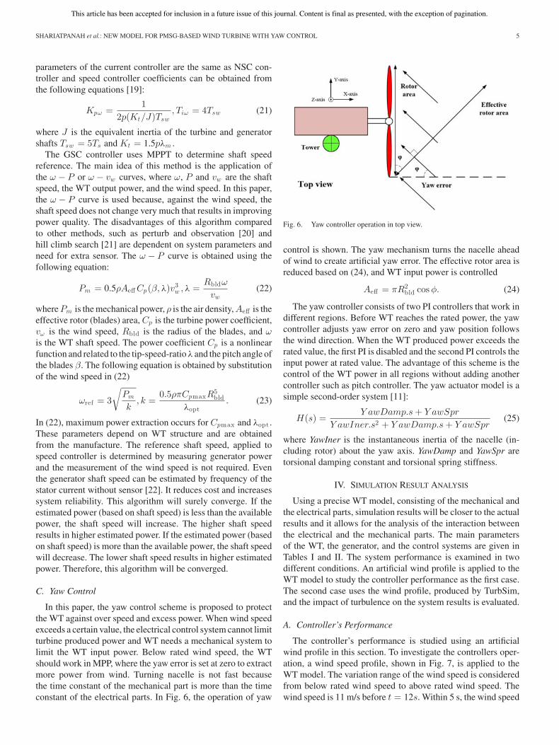
In this paper, the yaw control scheme is proposed to protectthe WT against over speed and excess power. When wind speedexceeds a certain value, the electrical control system cannot limitturbine produced power and WT needs a mechanical system tolimit the WT input power. Below rated wind speed, the WTshould work in MPP, where the yaw error is set at zero to extractmore power from wind. Turning nacelle is not fast becausethe time constant of the mechanical part is more than the timeconstant of the electrical parts. In Fig. 6, the operation of yaw
Fig. 6. Yaw controller operation in top view.
control is shown. The yaw mechanism turns the nacelle aheadof wind to create artificial yaw error. The effective rotor area isreduced based on (24), and WT input power is controlled
Aeff = πR2bld cos φ. (24)
The yaw controller consists of two PI controllers that work indifferent regions. Before WT reaches the rated power, the yawcontroller adjusts yaw error on zero and yaw position followsthe wind direction. When the WT produced power exceeds therated value, the first PI is disabled and the second PI controls theinput power at rated value. The advantage of this scheme is thecontrol of the WT power in all regions without adding anothercontroller such as pitch controller. The yaw actuator model is asimple second-order system [11]:
H(s) =Y awDamp.s + Y awSpr
Y awIner.s2 + Y awDamp.s + Y awSpr(25)
where YawIner is the instantaneous inertia of the nacelle (in-cluding rotor) about the yaw axis. YawDamp and YawSpr aretorsional damping constant and torsional spring stiffness.
IV. SIMULATION RESULT ANALYSIS
Using a precise WT model, consisting of the mechanical andthe electrical parts, simulation results will be closer to the actualresults and it allows for the analysis of the interaction betweenthe electrical and the mechanical parts. The main parametersof the WT, the generator, and the control systems are given inTables I and II. The system performance is examined in twodifferent conditions. An artificial wind profile is applied to theWT model to study the controller performance as the first case.The second case uses the wind profile, produced by TurbSim,and the impact of turbulence on the system results is evaluated.
A. Controller’s Performance
The controller’s performance is studied using an artificialwind profile in this section. To investigate the controllers oper-ation, a wind speed profile, shown in Fig. 7, is applied to theWT model. The variation range of the wind speed is consideredfrom below rated wind speed to above rated wind speed. Thewind speed is 11 m/s before t = 12s. Within 5 s, the wind speed
This article has been accepted for inclusion in a future issue of this journal. Content is final as presented, with the exception of pagination.
6 IEEE TRANSACTIONS ON ENERGY CONVERSION
Fig. 7. Wind speed profile.
Fig. 8. Active power, shaft speed, and mechanical torque.
reaches 19 m/s and remains at this value for 4 s. The wind speedis reduced within 4 s from t = 21 s and reaches the rated valueand then the system returns to the normal condition.
In Fig. 8, the generated power and the shaft speed are in adesirable range and the system is stable. The yaw controllerstarts working when the wind speed is increased. Due to thetime constant of the mechanical parts, after about 1 s, the shaftspeed and the output power are controlled (limited). The powerfluctuation is increased and power quality is reduced in the yawoperation area. The shaft speed has no fluctuation because itsinertia is large and according to (6), torque fluctuation can causefluctuation on power.
The yaw controller sets yaw error at zero and the WT rotoralways faces the wind. Increasing the wind speed, the yaw con-troller task is changed and the yaw error angle is increased (seeFig. 9). The maximum yaw rate limit depends on the WT rotorarea with a maximum value of 3 rad/s for small WT [23]. In thispaper, the maximum yaw rate limit is considered π/2 rad/s. Thepower fluctuation during yaw error is because of the mechanicalcontroller nature. The impact of yaw error on power quality waspredictable [24].
Fig. 9. Nacelle position and yaw error angle.
Fig. 10. d − q components of the generator and network currents.
The electrical controllers have proper performance duringyaw action and the system remains stable during and after yawoperation, as shown in Figs. 8 and 10. The power is limitedwhile the generator and network currents are controlled at theirmaximum values. The PI controller’s limits and antiwind uptechnique are utilized as such the controllers work at saturatedcondition during the yaw operation above rated wind speed.The network currents show less variation than the generatorstator currents, due to the existence of the dc link capacitorand its controller. The generator current fluctuations can causevariations on the capacitor voltage, as shown in Fig. 11. Thevariations, however, are in an acceptable range.
B. Impact of Turbulence on the Controllers
The impact of turbulence on the WT controller performanceis studied in this section and it will be shown that the controllerswork very well in this condition. A wind speed profile, shown inFig. 12 for the hub height, is generated by TurbSim. It is a 3-Dwind that blows to the blades with different velocities. In the
This article has been accepted for inclusion in a future issue of this journal. Content is final as presented, with the exception of pagination.
SHARIATPANAH et al.: NEW MODEL FOR PMSG-BASED WIND TURBINE WITH YAW CONTROL 7
Fig. 11. DC link voltage.
Fig. 12. Wind profile at hub height.
Fig. 13. Impact of yaw control on the yaw error and nacelle position.
normal condition, the yaw controller tries to balance the lateralaerodynamic forces and adjust the yaw error to zero. Increasingthe wind speed at t = 14 s, the yaw controller begins increasingthe yaw error angle to reduce the effective rotor area, as shownin Fig. 13. Due to the time constant of the mechanical system,the yaw controller needs about 1 s to limit input power. Theeffects of the wind velocity variations on the nacelle positionand the yaw error are visible in Fig. 13.
The effects of the turbulent wind and the yaw control onthe output power, the mechanical torque, and the shaft speed
Fig. 14. Impact of yaw control on the power, torque, and speed.
Fig. 15. d − q components of the generator and network currents in turbulentwind.
are depicted in Fig. 14. Generally, the wind speed variationand MPPT action justify the power variations. It is important tomention that the yaw mechanism time constant may cause a timedelay in controlling output power. As can be seen in Fig. 14,in spite of taking action of the yaw controller, the output powerexceeds 12 kW for about 1 s. From t = 13 s to t = 18 s, theelectrical controller does not track the optimal reference speedwhile the yaw controller is operating. Due to MPPT relation,the fluctuations on the output power cause the fluctuations onthe reference speed in this period. In this mode, the efficiencyof the WT is reduced to limit the input power. After decreasingthe wind speed, the WT controllers return to normal conditionand the optimal speed is followed by the controller.
The generator and network currents are shown in Fig. 15.The d-component of the generator current and the q-componentof the network current are set at zero to realize unity power
This article has been accepted for inclusion in a future issue of this journal. Content is final as presented, with the exception of pagination.
8 IEEE TRANSACTIONS ON ENERGY CONVERSION
Fig. 16. DC link voltage in turbulent wind.
Fig. 17. Moment about yaw-bearing in turbulent wind.
factor. The other current components are determined by outercontroller loops. The dc bus is controlled very well, as shown inFig. 16. The yaw motion can cause excess loads on WT structuredue to rotor gyroscopic effect and variable wind forces. In thisregard, the yaw-bearing moments are shown in Fig. 17. Whenthe WT output power is controlled by yaw controller, the rotorplane is not perpendicular to the wind speed, therefore, theloads (e.g., gyroscopic moments) on the yaw bearing will bebigger in comparison with normal conditions. The loads areincreased at t = 14 s because the yaw controller is operating.The variable wind forces and gyroscopic moments should beconsidered in yaw controller design because they can damagethe WT structure.
V. CONCLUSION
In this paper, a PMSG WT with yaw control was modeled.This model uses three software including TurbSim, FAST, andSimulink to simulate the wind profile, the WT direct drive, andthe electrical parts. The electrical controllers were designed forGSC and NSC in d − q reference frame and PSF method wasused to implement MPPT. These controllers control reactivepower and real power independently. The proposed new model,considering electrical and mechanical aspects, was utilized toevaluate the overall controller performance. The model showedthe effectiveness of the yaw scheme to protect WT against overspeed and excess power. The results also indicated the impactof the yaw operation on the electrical system.
APPENDIX
TABLE IWIND TURBINE DATA
TABLE IIELECTRICAL PARTS PARAMETERS
REFERENCES
[1] Y. Song, X. Yin, G. Lebby, and L. Weng, “A direct approach to achievingmaximum power conversion in wind power generation systems,” in Proc.6th Int. Symp. Neural Netw.: Adv. Neural Netw.—Part III, 2009, vol. 5553,pp. 1112–1121.
[2] J. S. Thongam and M. Ouhrouche, “MPPT control methods in windenergy conversion systems,” in Fundamental and Advanced Topicsin Wind Power, R. Carriveau, Ed. InTech, Jul. 2011, pp. 339–359.DOI: 10.5772/21657. Available: http://www.intechopen.com/books/fundamental-and-advanced-topics-in-wind-power/mppt-control-methods-in-wind-energy-conversion-systems
[3] A. Kusiak and Z. Zhang, “Adaptive control of a wind turbine with datamining and swarm intelligence,” IEEE Trans. Sustainable Energy, vol. 2,pp. 28–36, Jan. 2011.
[4] V. Galdi, A. Piccolo, and P. Siano, “Designing an adaptive fuzzy controllerfor maximum wind energy extraction,” IEEE Trans. Energy Convers.,vol. 23, pp. 559–569, Jun. 2008.
[5] K.-H. Kim, Y.-C. Jeung, D.-C. Lee, and H.-G. Kim, “Robust control ofPMSG wind turbine systems with back-to-back PWM converters,” inProc. 2nd IEEE Int. Symp. Power Electron. Distrib. Generat. Syst., Hefei,China, Jun. 2010, pp. 433–437.
[6] E. B Muhando and T. A. T. Funabashi, “Gain-scheduled control for WECSvia LMI techniques and parametrically dependent feedback—Part II: Con-troller design and implementation,” IEEE Trans. Ind. Electron., vol. 58,no. 1, pp. 57–65, Jan. 2011.
This article has been accepted for inclusion in a future issue of this journal. Content is final as presented, with the exception of pagination.
SHARIATPANAH et al.: NEW MODEL FOR PMSG-BASED WIND TURBINE WITH YAW CONTROL 9
[7] S. Li, T. A. Haskew, R. P. Swatloski, and W. Gathings, “Optimal anddirect-current vector control of direct-driven PMSG wind turbines,” IEEETrans. Power Electron., vol. 27, no. 5, pp. 2325–2337, May 2012.
[8] N. P. W. Strachan and D. Jovcic, “Stability of a variable-speed permanentmagnet wind generator with weak ac grids,” IEEE Trans. Power Del.,vol. 25, no. 4, pp. 2779–2788, Oct. 2010.
[9] R. Fadaeinedjad, M. Moallem, and G. Moschopoulos, “Simulation ofa wind turbine with doubly-FED induction generator by FAST andSimulink,” IEEE Trans. Energy Convers., vol. 23, no. 2, pp. 690–700,Nov. 2008.
[10] B. Jonkman, “Turbsim user’s guide: Version 1.50,” National RenewableEnergy Laboratory, Golden, CO, USA, Tech. Rep. NREL TP-500-46198,Sep. 2009.
[11] J. M. Jonkman and M. L. J. Buhl. (2005, Aug.). FAST user’sguide. National Renewable Energy Laboratory (NREL), Golden,CO, USA. Tech. Rep. NREL/EL-500-38230, [Online]. Available:http://wind.nrel.gov/designcodes/simulators/fast/
[12] T. Kane and D. Levinson, Dynamics: Theory and Applications. NewYork, NY, USA: McGraw-Hill, 1985.
[13] M. Blundell and D. Harty, The Multibody Systems Approach to Vehicle Dy-namics. New York, NY, USA: Elsevier Science and Technology Books,2004.
[14] P. J. Moriarty and A. C. Hansen. (2005, Dec.). AeroDyn theory manual.[Online]. Available: www.nrel.gov
[15] O. Anaya-Lara, J. Ekanayake, and P. Cartwright, Wind Energy Genera-tion Modelling and Control. New York, NY, USA: Wiley, 2009, ch. 6,pp. 103–106.
[16] G. F. Franklin, J. Powell, and A. Emami-Naeini, Feedback Control ofDynamic Systems, 5th ed. Englewood Cliffs, NJ, USA: Prentice-Hall,2006.
[17] A. Yazdani and R. Iravani, Voltage-Sourced Converters in Power Systems:Modeling, Control, and Applications. New York, NY, USA: Wiley, Mar.2010.
[18] D. Mehrzad, J. Luque, and M. C. Cuenca, “Vector control of PMSG forgrid-connected wind turbine applications,” M.S. thesis, Aalborg Univ.,Inst. Energy Technol., Aalborg, Denmark, 2009.
[19] M. O. Mora, “Sensorless vector control of PMSG for wind turbine ap-plications,” M.S. thesis, Aalborg Univ., Inst. Energy Technol., Aalborg,Denmark, Jun. 2009.
[20] Y. Xia, K. H. Ahmed, and B. W. Williams, “A new maximum power pointtracking technique for permanent magnet synchronous generator basedwind energy conversion system,” IEEE Trans. Power Electron., vol. 26,no. 12, pp. 3609–3620, Dec. 2011.
[21] K. Tan and S. Islam, “Optimal control strategies in energy conversion ofPMSG wind turbine system without mechanical sensors,” IEEE Trans.Energy Convers., vol. 19, no. 2, pp. 392–399, Jun. 2004.
[22] J. S. Thongam, P. Bouchard, R. Beguenane, A. F. Okou, and A. Merabet,“Control of variable speed wind energy conversion system using a windspeed sensorless optimum speed MPPT control method,” in Proc. IECON37th Annu. Conf. IEEE Ind. Electron. Soc., Nov. 2011, pp. 855–860.
[23] J. Jonkman, J. van Dam, and T. Forsyth, “Investigation of the IEC safetystandard for small wind turbine design through modeling and testing,”presented at the ASME Wind Energy Symp, Reno, NV, USA, Jan. 2003.
[24] R. Fadaeinedjad, G. Moschopoulos, and M. Moallem, “The impact oftower shadow, yaw error, and wind shears on power quality in a wind-diesel system,” IEEE Trans. Energy Convers., vol. 24, no. 1, pp. 102–111,Mar. 2009.
Hamid Shariatpanah was born in Sirjan, Iran, in1988. He received the B.S. and M.Sc. degrees in elec-trical engineering from Shahid Bahonar Universityof Kerman, Kerman, Iran, and Graduate Universityof Advanced Technology, Kerman, Iran, in 2010 and2012, respectively.
His research interests include wind energy, controlsystems, hybrid network, and power electronics.
Roohollah Fadaeinedjad (M’08) was born inKerman, Iran, in 1969. He received the B.S. andM.Sc. degrees in electrical engineering from ShirazUniversity, Shiraz, and Isfahan University of Tech-nology, Isfahan, Iran, in 1992 and 1995, respectively.He received the Ph.D. degree in electrical engineer-ing from University of Western Ontario, London,Canada, 2008.
From 1996 to 1999, he was with Shahid BahonarUniversity of Kerman as a Lecturer. From 1999 to2004, he worked in Protection and Control Depart-
ments of Kerman Regional Electric Company (KREC) and Rasanir Companyas a Senior Protection Engineer and Project Manager. He is currently an Assis-tant Professor in the Department of the Electrical and Computer Engineering,Graduate University of Advanced Technology, Kerman, Iran. His research inter-ests include wind energy, control systems, power electronics, and power systemprotection.
Masood Rashidinejad (M’06) received the B.Sc. de-gree in electrical engineering and the M.Sc. degreein systems engineering from Isfahan University ofTechnology, Isfahan, Iran. He received the Ph.D. de-gree in electrical engineering from Brunel University,London, U.K., 2000.
He is currently an Associate Professor in theDepartment of the Electrical Engineering, ShahidBahonar University of Kerman, Kerman, Iran. Hiscurrent research interests include power system anal-ysis, power system planning, renewable energy, re-
newable planning, reliability assessment and risk management, power systemcomputations, power system optimization and economics, electricity restructur-ing and energy management, and power system operation.