A Seawall Design with a Revetment and the Wave Reflector to Protect
Coast and Maintain the Position of Maron Coast Line Semarang
Nalarsih
Faculty of Engineering, University of Veteran, Sukoharjo 5751
Abstract. Coastal areas is a very strategic location and has a high economic value due to the transition
between land and water. However, it also causes a lot of problems. Semarang is a city in Indonesia, located
on the north coast of Java. This research was conducted in Maron Beach as the location of the research object.
Longshore sediment transport the which cause silting, sedimenttaion, abrasion and erosion can change the
coastline. Therefore, the main reason being to conduct research on coastal protection. This study is a sea wall
design using water depth 40 cm, 30 ° slope of the sea wall, curved reflector Compared with two different
wave is 1Hd and 1.5 Hd on it. The result of the selection of materials between wood and concrete, concrete is
more stable against big waves used. Test results on a slope of 30 ° curved 10cm (model A ) and a slope of
30 ° curved 15cm (model B ), that is capable of reducing the model B is evidenced by the large wave
reflection coefficient ( Kr ) is smaller than the model A is 0.199.
Keywords: Wave, Seawall, Curve.
1. Introduction
Maron beach is the location of the research in Semarang, Central Java, Indonesia. The existence
reclamation around the coast, making high tides so the impact on coastal protection facilities and tourist
facilities around it.
Coastal abrasion, longshore sediment transport caused the shallowing the river inflow Silandak because
material deposition of sediment transport, shoreline changes around Maron beach, jetty indicated the cause to
the flow in the river Silandak, and the presence of the wave character of Maron Beach is located on the ocean
waves shallow with a wave period of 5-6 seconds Leonardus Loan Rah Utomo and Muflikhudin [1].
Fig. 1. Design a model the laying of on the beach Maron Semarang
Previous research by Yowono Nur, Boby Primatama [2] is very supportive of this the research, which is
a model of innovative and economical revetment, slope of a model experiment carried out with the use of
wood and multiplexs, curved angles below 40 ° and 60 ° angle equivalent, on the slope of the given block of
wood to obtain the reflection and run-up smallest angle but based on the model used only one kind of
placement of block and only one formation of. Corresponding author.
E-mail address: [email protected].
The position Seawall reflector
2015 2nd International Conference on Geological and Civil Engineering IPCBEE vol. 80 (2015) © (2015) IACSIT Press, Singapore
DOI: 10.7763/IPCBEE. 2015. V80. 12
57
Based on that, the need to protect the coast of the optimal form of protective and economical buildings,
such as modifying the shape of a sea wall to reflect waves occur, without prejudice to the existence of these
waves. Design of coastal protection function properly need to make the construction of the prototype in the
form of construction of the corresponding waves (sea wall reflector) as blue sketch placed at the edge of the
breakwater there is shown in Fig. 1.
2. Literature Review
Reference visible indicates that this research is to understand and obtain the optimal seawall that has the
smallest wave refeleksi. Some of previous the research have sloping seawall be used as a reference.
If the protection of the natural beach does not exist, then it can be done in an artificial coastal protection
(artificial), to protect the artificial beach can be done through the five ways one of them is the retrofitting of
the beach with a seawall or revetment so resistant to wave action, Nur Yowono [3].
The amount of the effectiveness of a seawall is shown the resulting reflection coefficient is small, which
the large reflection coefficient (Kr) is the parameter of the reflection wave is defined as the ratio of the
reflected wave height (Hr) and high wave comes (Hi) according to the precepts of Dharma, IGB [4].
minmax
min
HH
HH
H
HK maks
i
rr
(4)
By Triatmodjo B [5], the wave will be reflected on an barrier partially or completely. A building that has
sloping sides and is made of rubble mount can absorb wave energy mount more than erect buildings and
massive. In building a vertical, smooth, and impermeable wall, the wave will be reflected entirely. Based on
the model test, the reflection coefficient for various building types are shown in Table 1.
Table 1: Coefficient of reflection
No Building type Coefficient of reflection (Kr)
1 Vertical wall with a peak on the water 0,70 – 1,00
2 Vertical wall with the top of the submerged 0,50 – 0,70
3 Piles of stone hypotenuse 0,30 – 0,50
4 Piles of concrete blocks 0,30 – 0,50
5 Vertical buildings with damper 0,05 – 0,20
So that made the research was based on a survey of the literature, found that there are no search results
conducted on the use of wave reflection from sloping seawall revetment block and head curved the same as
the model of this the research, both the size mapun variables.
3. Experimental Set-Up, Procedure and Test Programme
Seawall design that made the first stage using wood, multiplex and aluminum compared with a mixture
of sand stone bricks and cast composite curved to fit the diameter used is 10 cm and 12.5 cm. On the slope
field given the size of the block of wood 4,8cm x4,8cmx 4,8cm. Assuming srtuktur stable slope. Probe used
is 7, put right in front of the seawall models probes 6 and 7, the next 1m probes 4 and 5, the next 4m, probe 3,
the next 6m and 15m probe 2 probe 1.
Experimental research carried in a wave flume Assessment Institute for Dynamics of Yogyakarta,
Indonesia. Dimensions and characteristics of the wave flume used for this study are and the picture of flume
at Fig. 2 :
a. Flume length 50 m
b. Flume width 2 m
c. Flume depth 1.6 m
d. Water depth, d 0.4 m
e. Waves used in this study Regular wave
f. Incident wave height Hi 0.05–0.30 m
58
g. Wave period (T ) 1–3 s
h. Type of seawall Impermeable and block revetment
i. Dimension of the seawall 1.85 m width ×H 2.50 m height seawall
j. Dimension of the strcture seawall 0.10 m ×H 0.05 m ×L0.05 m
k. Type of wave generator Piston type generator
l. Angle between seawall surfacec 30°
Some of the range of normalized hydrodynamic parameters obtained are:
- Incident wave steepness, Hi / L 0,006-0,11
- Relative water depth, d / L 0, 09-0,45
- Relative wave height, Hi / d 0, 07-0,54
Jendela KacaSaringan Gelombang Wave Prove
Pembangkit
Gelombang
Peredam Gelombang
Rel
Peredam
Gelombang
5.00 5.00 5.00 15.00 5.00 4.00 10.50
Papan Gelombang
Lubang Drainase
TAMPAK ATAS
TAMPAK SAMPING
Jendela KacaSaringan Gelombang Wave Prove
Pembangkit
Gelombang
Peredam Gelombang Dasar Saluran Lubang Drainase
Rel
Peredam
Gelombang
5.00 5.00 5.00 15.00 5.00 4.00 10.50
Jendela KacaSaringan Gelombang Wave Prove
Pembangkit
Gelombang
Peredam Gelombang
Rel
Peredam
Gelombang
5.00 5.00 5.00 15.00 5.00 4.00 10.50
Papan Gelombang
Lubang Drainase
TAMPAK ATAS
TAMPAK SAMPING
Jendela KacaSaringan Gelombang Wave Prove
Pembangkit
Gelombang
Peredam Gelombang Dasar Saluran Lubang Drainase
Rel
Peredam
Gelombang
5.00 5.00 5.00 15.00 5.00 4.00 10.50
Fig. 2. Layout Wave Sensor Model
A total of 2390 data is taken to carried a regular wave with the same wave height, wave period and slope
walls. Seven probes were be used to measure the wave and the reflected wave profiles. Mike uses software to
analyze the wave profile to obtain the reflected wave height. Intake number of probes is basically using the
theory that the use of probes described by Goda and Suzuki [6], seven probes better of the two probes in
improving the resolution of the wave. First, the waves generated without running the sea wall in the flume.
History wave measured in this situation be used as an incident wave field.
4. Results and Discussions
4.1. Experimental Design Material Selection
Seawall research conducted at an angle of 30°, and 35 in a wave conditions Maron Beach then used
Curves (R) 1 is 10 cm and Curves (R) 2 is 12.5 cm at Fig. 3.
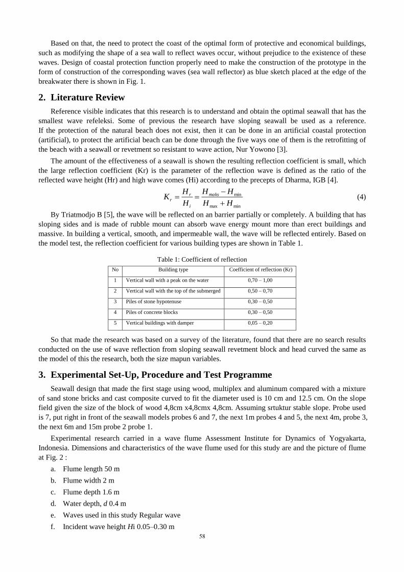
4.1.1. Experiments on smooth condition with wood, large angle of 30°, curved 10 cm
Fig. 3. Experimental 1a models
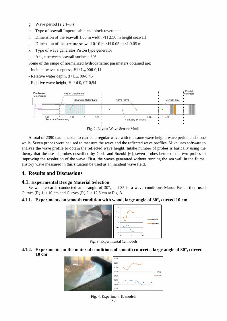
4.1.2. Experiments on the material conditions of smooth concrete, large angle of 30°, curved 10 cm
Fig. 4. Experiment 1b models
59
Based on the experimental material selection, shown in Fig. 3 and Fig. 4 that the wave line graph formed
between wood and concrete material, which is produced between the minimum and the maximum is more
stable in the concrete material experiment, so that in future experiments using concrete materials.
4.2. Eksperimen Design
4.2.1. Model Test A, results at water depth of 40 cm, at an angle of 30, curved 1 Hd = 10 cm as in Table 2.
Table 2: Calculation coefficient of reflection model test A
Model A Front of Probe Behind of the Probe Hi Hr Kr
Hmaks Hmin Hmaks Hmin
m m m m m m
experiment 1 0.475 0.057 0.375 0.165 0.5035 0.105 0.395
experiment 2 0.475 0.057 0.375 0.165 0.5035 0.105 0.395
experiment 3 0.475 0.057 0.375 0.165 0.5035 0.105 0.395
experiment 4 0.475 0.057 0.375 0.165 0.5035 0.105 0.395
experiment 5 0.475 0.057 0.375 0.165 0.5035 0.105 0.395
average of Kr 0.395
(a) Sea waves in stable condition (b) High sea wave conditions
Fig. 5. Model Test Results 30 angle, curved 1 Hd
Experimental results of A model, when the waves come crashing condition of the sea wall at an
inclination of 30 ° and 10 cm curved reflection occurs and some of the water in a large structure with wave
reflection 0.395, shown in the wave line in Fig. 5 (a). Then the image (b) the conditions Maron Beach wave
after reflection, water back sliding on the structure that forms the greater pressure in front of the building, so
that the structure is said to be able to reduce wave.
4.2.2. Model Test B, results at water depth of 40 cm, at an angle of 30, curved 1.5 Hd = 15 cm as in Table 3.
Table 3: Calculation coefficient of reflection model test B
Model B Front of Probe Behind of the Probe Hi Hr Kr
Hmaks Hmin Hmaks Hmin
m m m m m m
experiment 1 0.166 0.00056 0.21525 0.0901 0.16628 0.16572 0.996632
experiment 2 0.167 0.00056 0.21525 0.0901 0.167282 0.1667178 0.996626
experiment 3 0.168 0.00056 0.21525 0.0901 0.168282 0.1677179 0.996647
experiment 4 0.166 0.00056 0.21525 0.0901 0.166282 0.1657178 0.996606
experiment 5 0.167 0.00056 0.21525 0.0901 0.167282 0.16671785 0.996627
average of Kr 0.199326
60
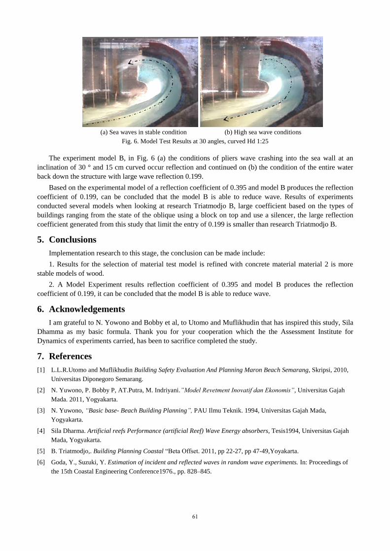
(a) Sea waves in stable condition (b) High sea wave conditions
Fig. 6. Model Test Results at 30 angles, curved Hd 1:25
The experiment model B, in Fig. 6 (a) the conditions of pliers wave crashing into the sea wall at an
inclination of 30 ° and 15 cm curved occur reflection and continued on (b) the condition of the entire water
back down the structure with large wave reflection 0.199.
Based on the experimental model of a reflection coefficient of 0.395 and model B produces the reflection
coefficient of 0.199, can be concluded that the model B is able to reduce wave. Results of experiments
conducted several models when looking at research Triatmodjo B, large coefficient based on the types of
buildings ranging from the state of the oblique using a block on top and use a silencer, the large reflection
coefficient generated from this study that limit the entry of 0.199 is smaller than research Triatmodjo B.
5. Conclusions
Implementation research to this stage, the conclusion can be made include:
1. Results for the selection of material test model is refined with concrete material material 2 is more
stable models of wood.
2. A Model Experiment results reflection coefficient of 0.395 and model B produces the reflection
coefficient of 0.199, it can be concluded that the model B is able to reduce wave.
6. Acknowledgements
I am grateful to N. Yowono and Bobby et al, to Utomo and Muflikhudin that has inspired this study, Sila
Dhamma as my basic formula. Thank you for your cooperation which the the Assessment Institute for
Dynamics of experiments carried, has been to sacrifice completed the study.
7. References
[1] L.L.R.Utomo and Muflikhudin Building Safety Evaluation And Planning Maron Beach Semarang, Skripsi, 2010,
Universitas Diponegoro Semarang.
[2] N. Yuwono, P. Bobby P, AT.Putra, M. Indriyani.”Model Revetment Inovatif dan Ekonomis”, Universitas Gajah
Mada. 2011, Yogyakarta.
[3] N. Yuwono, “Basic base- Beach Building Planning”, PAU Ilmu Teknik. 1994, Universitas Gajah Mada,
Yogyakarta.
[4] Sila Dharma. Artificial reefs Performance (artificial Reef) Wave Energy absorbers, Tesis1994, Universitas Gajah
Mada, Yogyakarta.
[5] B. Triatmodjo,. Building Planning Coastal “Beta Offset. 2011, pp 22-27, pp 47-49,Yoyakarta.
[6] Goda, Y., Suzuki, Y. Estimation of incident and reflected waves in random wave experiments. In: Proceedings of
the 15th Coastal Engineering Conference1976., pp. 828–845.
61