A Solenoidal Detector for Deeply Virtual Compton Studies at Luminosities ≥ 10 37 / cm -2 s -1 and energies 6 – 12 GeV Charles E. Hyde-Wright, Gail E. Dodge, Gagik Gavalian, David Hayes, Lawrence B. Weinstein Old Dominion University, Norfolk VA Bernard Michel, Pierre-Yves Bertin Universit` e Blaise Pascal, Clermont-Ferrand, France J. P. Chen, Eugene Chudakov, Bogdan Wojtsekhowski, Sirish Nanda, Bodo Reitz, Robert Feuerbach, Javier Gomez Jefferson Laboratory, Newport News, VA Ron Gilman, Elena Kuchina Rutgers University, New Brunswick, NJ The Jefferson Lab Hall A Collaboration (Dated: 6 December 2004) We propose a solenoidal detector for exclusive electro-production reactions, par- ticularly Deeply Virtual Compton Scattering (DVCS): ep → epγ and Double DVCS ep → epl + l - . The detector is built around a 1.1 m diameter, 1 m long, 2 Tesla solenoid, with a liquid hydrogen target at the upstream end of the solenoid. The downstream end-cap is instrumented for angles ≥ 100 milli-radians with a highly segmented high resolution total absorption calorimeter, for electron and photon de- tection. For scattering angles less than 45 ◦ , the barrel is instrumented with a Gas Electron Multiplier (GEM) based Radial Time Projection Chamber (RTPC) and with plastic scintillator for identification and tracking of the recoil protons. In addi- tion to the calorimeter, the End-cap is also instrumented with a 10 cm deep TPC and a scintillator array for e/γ/p discrimination. As an upgrade, the return yoke of the solenoid can be instrumented with coarse grained detectors for muon identification for coherent J Ψ and di-lepton production studies.
Transcript
A Solenoidal Detector for Deeply Virtual Compton Studies at
Luminosities ≥ 1037/ cm−2s−1 and energies 6 – 12 GeV
Charles E. Hyde-Wright, Gail E. Dodge, Gagik
Gavalian, David Hayes, Lawrence B. Weinstein
Old Dominion University, Norfolk VA
Bernard Michel, Pierre-Yves Bertin
Universite Blaise Pascal, Clermont-Ferrand, France
J. P. Chen, Eugene Chudakov, Bogdan Wojtsekhowski,
Sirish Nanda, Bodo Reitz, Robert Feuerbach, Javier Gomez
Jefferson Laboratory, Newport News, VA
Ron Gilman, Elena Kuchina
Rutgers University, New Brunswick, NJ
The Jefferson Lab Hall A Collaboration
(Dated: 6 December 2004)
We propose a solenoidal detector for exclusive electro-production reactions, par-
ticularly Deeply Virtual Compton Scattering (DVCS): ep → epγ and Double DVCS
ep → epl+l−. The detector is built around a 1.1 m diameter, 1 m long, 2 Tesla
solenoid, with a liquid hydrogen target at the upstream end of the solenoid. The
downstream end-cap is instrumented for angles ≥ 100 milli-radians with a highly
segmented high resolution total absorption calorimeter, for electron and photon de-
tection. For scattering angles less than 45, the barrel is instrumented with a Gas
Electron Multiplier (GEM) based Radial Time Projection Chamber (RTPC) and
with plastic scintillator for identification and tracking of the recoil protons. In addi-
tion to the calorimeter, the End-cap is also instrumented with a 10 cm deep TPC and
a scintillator array for e/γ/p discrimination. As an upgrade, the return yoke of the
solenoid can be instrumented with coarse grained detectors for muon identification
for coherent JΨ and di-lepton production studies.
2
We demonstrate that this detector can function at luminosities of at least
1037/cm2/s. This will enable extremely high precision studies of many important
exclusive reactions.
Contents
I. Introduction 3
A. Kinematics 4
B. Deeply Virtual Compton Scattering 5
C. Double DVCS 7
II. Detection Strategy 8
III. Detector Design Criteria 9
A. Magnetic Field 10
1. Møller Electrons 10
2. Target and Scattering Chamber 12
B. π0/γ separation 13
C. Backgrounds 13
IV. Description of Solenoidal Detector 14
A. Solenoid 14
B. Particle ID 14
C. Calorimeter 15
D. Scintillator 15
V. Trigger 16
VI. Background Rates 17
A. Calorimeter 17
B. Scintillator 20
C. GEM based TPC 20
VII. Costs 22
3
A. TPC cost 22
B. Calorimeter 22
C. Solenoid 22
D. Scintillator 23
E. Electronics 23
VIII. Exclusivity 23
IX. Count Rates 24
A. DVCS 25
B. Charmonium 26
C. Conclusions 26
X. Bibliography 26
References 26
I. INTRODUCTION
Exclusive Deeply Virtual reactions provide access to a new class of observables, called
Generalized Parton Distributions (GPDs) [1]–[9]. The GPDs offer us the unprecedented
capability of constructing spatial images of the density of quarks inside the nucleon, as a
function of the quark wavelength [7], [8], [9]. In this proposal we specifically consider the
following reactions: Deep Virtual Compton Scattering (DVCS) ep → epγ; Deep Virtual π0
Production ep → epπ0; Doubly Deep Virtual Compton Scattering (D2VCS) ep → e′pl+l−,
and exclusive J/Ψ electro-production.
The final state phase space of these reactions is complicated. The cross sections are also
small: the DVCS cross section is O(α3) and the D2VCS cross section is O(α4). Thus high
luminosity combined with high acceptance is essential. Previous proposals for studies of
these reactions at 6–12 GeV at Jefferson lab have been designed around general purpose
equipment. In this proposal we explore the feasibility of a specialized detector designed
specifically for these reactions. Despite the technical challenges posed by these processes,
we are motivated by the intuition that exclusive Deep Virtual processes offer a number of
4
k k’
q’p
p’γ e p →e p
= +
Bethe-Heitler
+
VCS
VCS
→ξ-2
GPDξx+ ξx- +
DVCS
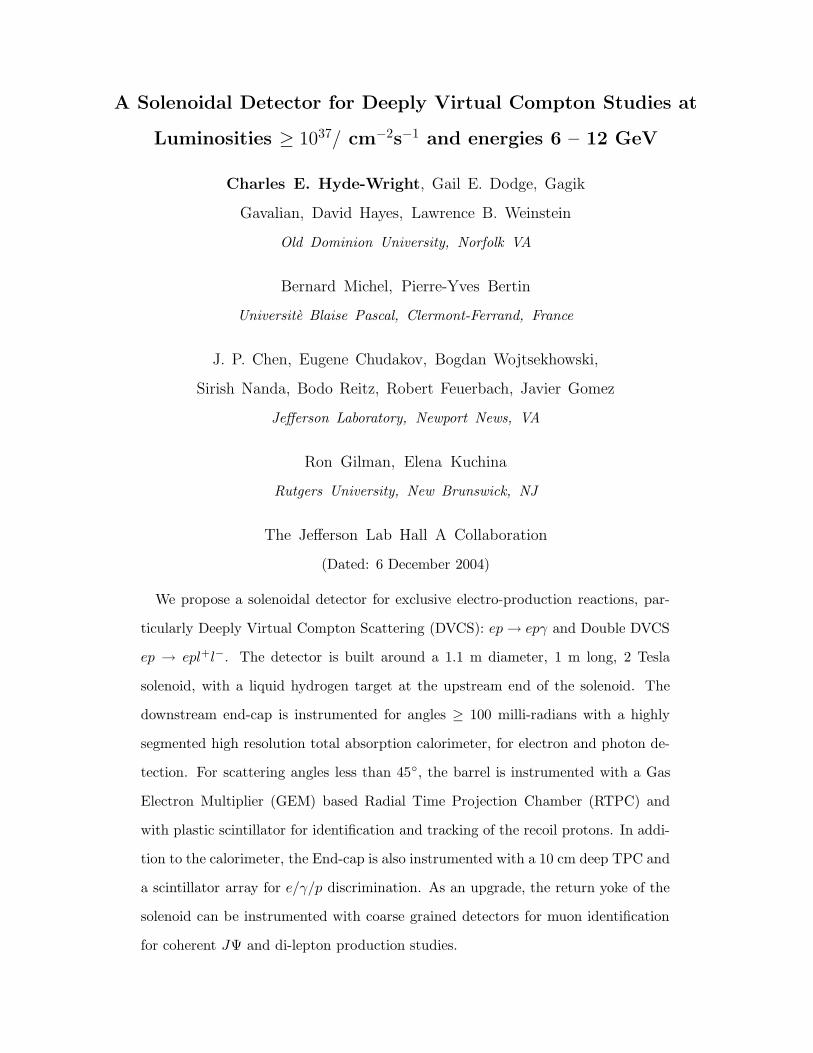
FIG. 1: Kinematics of the eN → eNγ reaction and the factorized DVCS amplitude. The kinematic
invariants are Q2 = −q2 = −(k − k′)2, xBj = Q2/(2p · q), t = (q − q′)2. In the Bjorken limit, the
skewness parameter ξ → xBj/(2 − xBj).
distinct advantages, which will permit a dedicated detector to be built at lower cost and
operate at much higher luminosity than a general purpose apparatus.
The experimental simplifications of Deep Virtual reactions are straight forward. In the
limit of modest momentum transfer to the recoiling nucleon (less than 1 GeV/c) almost
the entire beam energy is deposited in either: two electromagnetic showers (DVCS); three
electromagnetic showers (ep → epe+e−); or one shower and two muons (ep → epµ+µ−).
Thus very strong background rejection factors can be built into a hardware trigger. Secondly,
because the proton recoil momentum is generally 1/10th beam momentum, the precision of
measurement of the recoil proton can be roughly 10× worse than the electron and photon,
and still ensure exclusivity. Finally, since it is possible to measure all final state particles, the
reaction is over-complete. Thus exclusivity of the reaction can be established even without
measuring the magnitude of the momenta of all particles.
5
A. Kinematics
We define our kinematic variables for DVCS in Fig. 1. The skewness parameter is the
light-cone momentum transfer fraction:
ξ = (q − q′)+/(p+ p′)+ (1)
For D2VCS, the final photon q′ is time-like, and materializes as a di-lepton pair of momentum
q′ = k+ + k−.
B. Deeply Virtual Compton Scattering
For DVCS, we consider the following kinematic bounds: s > 4 GeV2, Q2 > 2 GeV2,
k′ > 1.5 GeV. The bounds on s and Q2 define the generally accepted region for inclusive
deep inelastic scattering. The lower bound on k′ is to ensure a clean separation between
electromagnetic showers and minimum ionizing tracks in the calorimeter.
The kinematics at 11 GeV are illustrated in Fig. 2. The DVCS cross section is roughly
proportional to the DIS cross section. For our initial design, we consider ≈ 30 a reasonable
upper bound for scattered electron detection, since the count rate is likely to fall rapidly at
higher angles. However, we also consider options for calorimetry at larger angles because of
the strong interest in achieving the highest possible Q2.
To avoid the high flux of Møller electrons, we do not instrument for angles smaller than
100 mr. In the target rest frame, the minimum momentum transfer to the proton −tmin is
achieved with the outgoing photon parallel to the ~q direction. DVCS events can be detected
in kinematics with θq < 0.1 rad with a loss of acceptance near the minimum momentum
transfer. We note that
−tmin ≈ =x2
BjM2
1 − xBj +M2x3Bj/Q
2
tmin − t(θγγ = 0.1) ≈ 0.1 GeV2. (2)
The last formula indicates that for those kinematics with θq < 0.1, the exclusion of photons
in a cone of 100 mrad around the beam line introduces only a small shift in the minimum
−t accessible experimentally.
In the ep → epγ reaction, the VCS amplitude interferes constructively with the Bethe-
Heitler (BH) amplitude, in which the photon is radiated by the electron. At Jefferson Lab,
6
FIG. 2: Kinematics of DIS at 11 GeV. The practical kinematics is bounded above by the s = 4
GeV2 line (blue), and on the left by the Q2 = 2 GeV2 line (red). Below the θq = 0.1 rad line there is
a loss of acceptance for DVCS at low −t = (q−q ′)2, since the photon is no longer detectable exactly
parallel to the ~q. Also, it is desirable to have a high threshold (≥ 1.5 GeV) in the calorimeter for
a trigger.
we use the BH amplitude as an amplifier and filter for the DVCS amplitude. One specific
observable is the cross section difference for leptons of opposite helicities. In our kinematics,
this cross-section difference is dominated by the interference of the imaginary part of the
DVCS amplitude with a known BH amplitude. The full expression for the difference in the
cross-section for leptons of opposite helicities is given by [5, 6]:
d5Σ
dQ2dxBdtdϕ=
d5 →σ
dQ2dxBdtdϕ− d5 ←σ
dQ2dxBdtdϕ(3)
7
=α3
2π2
(2 − y)
−t
√
K2
1 + e2
[
A sinϕ+B sin 2ϕ+ C sin 3ϕ
s′u′
]
. (4)
The variable ϕ is the azimuth of the hadron plane (~q ′ ⊗ ~p ′) with respect to the electron
scattering plane. The ϕ-dependent denominator s′u′ = −4(k · q′)(k′ · q′) originates from the
electron propagators of the BH process. y = q · p/k · p is the invariant inelasticity and in the
Bjorken limit the kinematic factor K2/(1 + e2) → (1 − xBj)(tmin − t)/~q 2. The A sinϕ term
is the leading twist contribution to the cross section difference. It is the sum of three (out
of four) quark GPDs:
A = F1(−t)H(ξ, t) + ξGM(−t)H(ξ, t) +−t
4M2F2(−t)E(ξ, t), (5)
H(ξ, t) = π∑
q
e2q [Hq(x = ξ, ξ, t) −Hq(x = −ξ, ξ, t)] (6)
where F1, GM , and F2 are the usual elastic form factors, and the definitions of H and Eare analogous to Eq. 6. The B sin 2ϕ term in Eq. 4 is a higher twist term, and is therefore
predicted to be suppressed by one power of√Q2 relative to the leading twist term. The
C sin 3ϕ term depends upon gluon helicity flip GPDs, and is expected to be much smaller
than the other terms. Precise measurements of the Q2-evolution of A, B, and C are an
important motivation for high statistics measurements of DVCS.
C. Double DVCS
In exclusive di-lepton pair production, factorization results from the large mass of the
di-lepton pair. Thus we can study Inverse DVCS with real photons and D2VCS at Q2 ≤ 1
GeV2. The imaginary part of the Double DVCS amplitude measures the Generalized Parton
Distributions (GPD) at the kinematic point:
=[
D2V CS]
∝ GPD(±η, ξ, t)
η ≈ Q2 −Q′ 2
2s+Q2 −Q′ 2
ξ ≈ Q2 +Q′ 2
2s+Q2 −Q′ 2(7)
with Q′ 2 = q′ 2 the mass of the di-lepton pair. In Eq. 7 we have exchanged the definitions
of η and ξ relative to Ref. [10], for consistency with our DVCS definitions. For Q2 < Q′ 2,
D2VCS measures the qq region of the Generalized Parton Distributions. Thus these reactions
8
measure the quark content of the meson cloud, or penta-quark, structure of the nucleon.
The imaginary part of the DDVCS amplitude is accessible experimentally by measuring
single spin asymmetries. In the DDVCS case, we also have direct access to the Real part of
the BH-DVCS interference, in a way that is only accessible in DVCS with the difference of
electron and positron scattering. In the DDVCS case, at fixed Q2, Q′ 2, and t, the Real part
of the BH*VCS interference is obtainred from the asymmetry for k+ ↔ k−.
In inclusive Drell-Yan production in high energy hadron reactions, it is necessary to put
a lower bound of 3 GeV on the di-lepton mass to remove the background of muons from
hadronic decays, especially open charm. However, in the constrained kinematics of exclusive
reactions these backgrounds disappear. The authors of [10] suggest that di-lepton masses
above 1.5 GeV are sufficient for factorization in γp→ pl+l− [10]. At this scale, (comparable
to baryon masses above 2 GeV, the usual criterion for DIS) the density of meson states is large
enough to have confidence in duality. Fig. 3 illustrates sample di-lepton decay kinematics.
We will present a more comprehensive analysis of this channel in a future update.
Figs. 2,3 illustrate that a maximum electron detection angle of 30 is a reasonable com-
promise for both DVCS and di-lepton detection. However, it is clear that larger detection
angles are desirable for higher virtuality DVCS and higher mass IDVCS and D2VCS.
II. DETECTION STRATEGY
The Hall A DVCS experiments E00-110 and E03-106 measured the DVCS process with
unshielded photon and proton detectors at a luminosity of 1037. The minimum angle of
a PbF2 calorimeter block relative to the beam is ≈ 10. The minimum angle of a proton
detector element is 15. In order to exploit the low-xBj region illustrated in Fig. 2, it is
necessary to detect photons in a small cone around a virtual photon direction as close as
100 mr from the beam.
To cope with the flux of low energy Møller flux we propose to shield all detectors with
a strong magnetic field. We believe this can achieve the combination of highest possible
luminosity, large solid angle for the proton detection, small angle capability for the photon,
and greatest flexibility for electron and photon detection. The luminosity is primarily limited
by the flux of low energy charged particles and photons from the target. The large acceptance
precludes shielding or a focussing spectrometer. A toroidal magnetic field requires a large
9
FIG. 3: Di-lepton decay kinematics for a 2.5 GeV mass di-lepton pair produced by a 9 GeV virtual
photon (Q2 = 1 GeV2). The ordinand is the cosine of the angle between the di-lepton momentum
direction and the direction of one of the leptons in the pair, evaluated in the lab-frame. The abscissa
is the same angle in the di-lepton rest-frame. The bounding angles of 9.4 and 27.9 contain 50%
of the dilepton phase space.
sacrifice in acceptance for the coils and support structure. The detector design presented
here, is modular and can be built in phases, to accommodate higher luminosity, higher
acceptance, and an expanded physics program. We present the detector concept in Fig. 4.
The following sections describe in more detail the performance criteria.
III. DETECTOR DESIGN CRITERIA
We consider a magnet-detector combination with the following capabilities.
10
• Electron and photon measurement from 0.1 rad to 30, relative to the beam line.
Angular resolution of 3 mr
Energy resolution of√E[3 − 5]%.
• Containment of the Møller electrons within the 0.1 rad cone.
• Luminosity of 1037 with a 1 cm long thin-walled LH2 target.
• Detection of protons in cone from 0.1 rad to 45, relative to beam line. Granularity of
proton detector to be discussed later but much coarser than photon detection.
• Upgrade capability to muon detection
• Upgrade capability to electron detection at angles 30–45. This is achievable by adding
coarse grained Pb-Glass outside the Solenoid coil, with or without the Barrel scintil-
lators replaced with a pre-radiator.
• Sufficient magnet field and tracking capability to track electrons sufficiently well to
distinguish e+/e−.
• π0 detection and γ/π0 discrimination in DVCS kinematics.
We present the detector concept in Fig. 4. The following sections describe in more detail
the and performance criteria.
If the photon is detected in a highly segmented calorimeter, a transverse resolution of
3 mm can be achieved. Thus the 3 mr angular resolution requirement places a minimum
distance from target to calorimeter of 1 m. Without any tracking, a 1 cm long target
contributes at most 1.25 mr to the angular resolution for electron scattering angles up to
30.
A. Magnetic Field
1. Møller Electrons
At scattering angles above 0.1 radian, the maximum perpendicular momentum of elec-
trons from Møller scattering is 10 MeV/c. In an axial magnetic field B, the radius of
11
= 2 T0Coil, B
Aµ38
Scint.
TPC
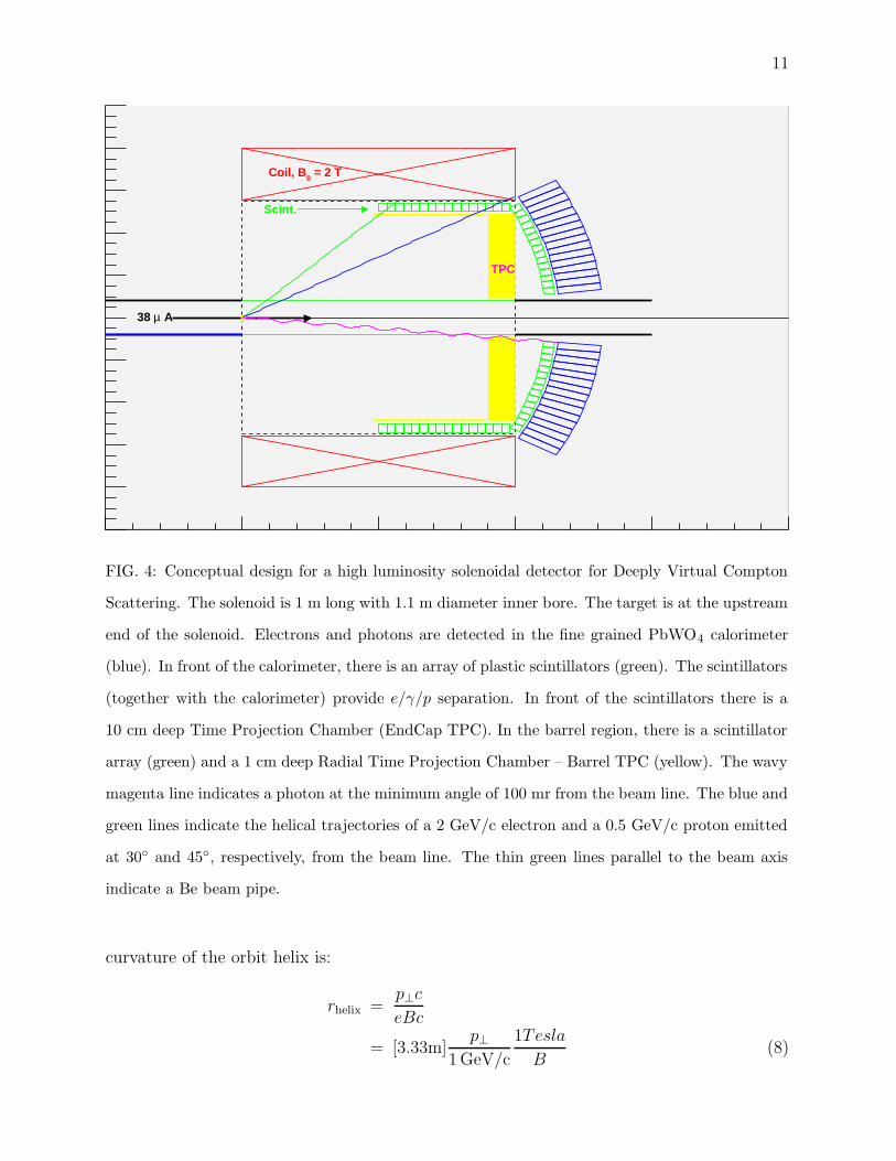
FIG. 4: Conceptual design for a high luminosity solenoidal detector for Deeply Virtual Compton
Scattering. The solenoid is 1 m long with 1.1 m diameter inner bore. The target is at the upstream
end of the solenoid. Electrons and photons are detected in the fine grained PbWO4 calorimeter
(blue). In front of the calorimeter, there is an array of plastic scintillators (green). The scintillators
(together with the calorimeter) provide e/γ/p separation. In front of the scintillators there is a
10 cm deep Time Projection Chamber (EndCap TPC). In the barrel region, there is a scintillator
array (green) and a 1 cm deep Radial Time Projection Chamber – Barrel TPC (yellow). The wavy
magenta line indicates a photon at the minimum angle of 100 mr from the beam line. The blue and
green lines indicate the helical trajectories of a 2 GeV/c electron and a 0.5 GeV/c proton emitted
at 30 and 45, respectively, from the beam line. The thin green lines parallel to the beam axis
indicate a Be beam pipe.
curvature of the orbit helix is:
rhelix =p⊥c
eBc
= [3.33m]p⊥
1 GeV/c
1Tesla
B(8)
12
To contain the Møller electrons within a beam pipe aperture defined by the 0.1 radian
detection cone at a distance of 1 m from the target requires rhelix < 5 cm, or a magnetic field
of 0.66 T. We have, however, chosen a central field of 2 T to give maximum flexibility in
designing the scattering chamber, while minimizing low energy background in the detectors.
2. Target and Scattering Chamber
We choose a minimum electron energy to detect of 1.5 GeV, to ensure a large signal over
background in the calorimeter. We also require less than 2 mr multiple scattering total in the
target and exit beam pipe, or 1.4 mr in each. This defines a maximum material thickness:
X/X0 ≤ [θmsPminβ/(15 MeV)]2
=[
1.4 · 10−3(1.5 GeV)/(0.015 GeV)]2
= 2% (9)
The 2% radiation length puts an upper bound on a liquid hydrogen target (X0 = 61.3
g/cm2) thickness of 17.4 cm. The target vacuum chamber can be either a spherical Al
chamber mated to a downstream beam pipe or thin walled Be tube. For Al:
2%X0(Al) = 1.8mm
2%X0(Be) = 7.0mm (10)
Based on the Hall A DVCS scattering chamber, we expect a 35 cm radius Al shell can be
made with a 1.8 mm wall thickness. Detailed background studies may allow a less stringent
beam pipe design, but we assume the 0.1 r scattered electrons should pass through the hemi-
spherical shell whereas the Møller electrons should be contained in a downstream beam pipe.
At 35 cm (centered at the downstream end of a 10 cm target) the beam pipe must be ≤ 3.5
cm in radius. To contain the Møller electrons of p⊥ ≤ 10 MeV within 3.5 cm, a magnetic
field of 2 T is required. We will use this as the default magnetic field design. Beyond the
end of the solenoid, the magnetic field on the axis decreases as B0/[1 + (z/rS)2]3/2. Thus
for a 1 m long solenoid of radius rS = 0.55 m, the Møller electrons remain contained within
100 mr for a distance 70 cm beyond the end of the solenoid.
The CMS detector at the LHC includes a 1 mm thick Be beam pipe, 8 cm in diameter
with a total length of 1.5 m. If this is reduced to 1.0 m, and possibly smaller radius, this
can achieve the 2% radiation length even for tracks at 100 mrad (0.7 mm radial thickness).
This is clearly the more elegant solution:
13
• Reduced multiple scattering at large angles
• Completely open geometry at large angles for detector upgrades.
• Møller electrons contained with B > 0.88 T.
• Backgrounds at detector insensitive to target placement
B. π0/γ separation
We assume that with fine grained calorimetry, double showers from π0 decays can be
resolved from γ showers if the transverse separation of the two showers exceeds twice the
Moliere radius rM . For PbWO4, rM = 2 cm. 50% of the π0 decays occur with opening angles
[2− (8/3)√
3]mπ/Epi. The maximum exclusive photon or π0 energy is 9 GeV (Fig. 2). π0/γ
resolution at this energy requires a flight path to the calorimeter of:
z > rMEπ/mπ = 1.33m (11)
If the calorimeter is placed at 1.1 m, the full π0/γ separation is achievable up to Eπ = 7.4
GeV
The size of the calorimeter is a dominant cost driver of this detector concept. We propose
to place the calorimeter in a shell at radius 1.12 m. For the kinematics with Eπ > 7.4
GeV, a dedicated run is required, with the target 25 cm upstream. This may increase the
backgrounds slightly, if some of the Møller electrons shower in the downstream beam pipe.
In this case, the magnetic field at the upstream target position will be ≈1.4 T. This is still
sufficient to contain the Møller electrons.
Another option is to place the calorimeter 50 cm downstream of the solenoid. This
significantly improves the γ/π0 separation. In this case the calorimeter area expands by a
factor of 2.25. However, with a Fe return yoke, this may allow the use of PMT, rather than
Avalanche Photo Diode (APD) readout of the calorimeter blocks. This will substantially
improve the energy resolution of the calorimeter. This option may also allow use of a
common calorimeter for DVCS and the proposed Primakov program.
14
C. Backgrounds
In DVCS, the final state photon must be detected in a small cone around the virtual
photon direction (typically < 200 mr half angle). However, the virtual photon direction
itself is very close to the beam line, generally 100–200 mr. Conversely, the recoil protons,
with momenta 400–1000 MeV/c must be detected in a cone of roughly 45 half angle around
the beam line.
IV. DESCRIPTION OF SOLENOIDAL DETECTOR
A. Solenoid
The magnet is a 2 T solenoid, 1 m long and 1.10 m inner bore diameter. To facilitate
an upgrade to include calorimetry at larger angles, the solenoid should be thin. Radial
thicknesses less than one radiation length are possible. Many variations on the magnet
are possible. Instead of a simple solenoid, the magnet could be segmented along the beam
line, with a series of coils of increasing radius, to avoid the cost of the stored energy in the
magnetic field at scattering angles > 45. Also, if the magnet is segmented in z (beam line)
it may be possible to incorporate polarized targets with the detector.
B. Particle ID
A high granularity calorimeter can distinguish e/γ from protons, pions, muons, etc. The
calorimeter also measures transverse position to 3mm and energy to 1%⊕ 3.5%√
E(1 GeV).
Coarse grained tracking detectors inside and behind a Fe return yoke can identify muons
for a exclusive di-lepton experiment. Factorization requires highest possible s and di-lepton
mass. Thus typical di-lepton energy will be ≥ 8 GeV, and to detect both leptons, the decay
phase space will be limited to leptons from 1/4 to 3/4 of the total di-lepton energy. Thus the
minimum muon momentum to detect is 2 GeV, and one of the two muons will always have
momentum above 4 GeV. With an absorber thickness of three hadronic interaction lengths
(the calorimeter is ≈ 1 interaction length) a µ/π resolving power of 20/1 can be achieved.
Since two particles must be identified, a π+π− rejection factor of 400:1 can be achieved with
a µ-counter upgrade.
15
A thick scintillator (> 4 cm) can resolve high energy hadrons (especially the recoil pro-
tons) from low energy photon background (97% below 3 MeV). Either this scintillator, or
a gas chamber can discriminate between electrons and γ-rays. A 4 cm scintillator has a
7.5% probability of converting a high energy γ-ray to a signal ≥ half of minimum ionizing.
Thus without the TPC in front of the calorimeter, there would be a 7.5% event sample with
ambiguous e/γ I.D.
C. Calorimeter
PbF2 is a high density Cerenkov medium. It offers the best combination of high resolution
and neutron/hadron immunity (except minimum ionizing signals). The E00-110 collabora-
tion measured a resolution of σE/E = 3%/√
(1 GeV)E with a test array. The cost of the
E00-110 132 element array is $800/crystal (3× 3 cm2×20X0). Total cost of crystals + PMT
+ Base+ cable approx $2000/channel. To completely instrument the calorimeter EndCap
requires 840 crystals for a total calorimeter cost estimate of $1.7M.
Although there may be a magnetic field solution with the calorimeter outside the field
region, we consider that the calorimeter probably requires Avalanche Photo Diode (rather
than PMT) readout.
APDs have a very high quantum efficiency (75%, but also high cost per surface area. Thus
APDs have been more commonly used with PbWO4 calorimeters. PbWO4 is a scintillator
with light emission ≥ 200 photons/MeV with 90% of light emitted within 100 ns. The Hall
B DVCS calorimeter couples APDs (5mm)2 to the back face (15 mm)2 of PbW04 crystals.
The unit cost of crystal, APD, and pre-amp is approximately $500. This corresponds to
the same unit cost $2000 per (3 cm)2 surface as the quoted above for PbF2 PMT combina-
tion. However, the Lead-Tungstate option requires four times the readout channels, unless
multiple channels are summed together in the pre-amp stage. The total yield for PbWO4
coupled to APDs is ≥ 2 photo-electrons/MeV. The Hall B Primakov experiment achieves
higher yields with PbWO4 coupled to PMTs.
16
D. Scintillator
Following the lead of E00-110, we consider that a coarse grained scintillator array is
sufficient to identify the protons with sufficient angular resolution to resolve the exclusive
channel. We consider an array of scintillator tiles of depth 4 cm, and (3 cm)2 granularity
matching the calorimeter blocks. Because the scintillators are in the magnetic field, they
must be read out either by Avalanche Photo-Diodes, or wave shifting fibres to [multi-channel]
PMTs. If the Visible Light Photon Detector (VLPC) technology is implemented at JLab, as
planned for the Hall D Start-Counter, then this technology could be used with wave shifting
fibres.
V. TRIGGER
The trigger is based on energy deposited in one or more showers in the calorimeter. We
assume the calorimeter is digitized by a 100 MHz pipeline ADC. We also require parallel
trigger logic that in real time can find local clusters in the calorimeter and in real time
compute approximate shower energy and Q2 (assuming the particle is an electron). The
E00-110, E03-106 DVCS experiments in Hall A used a non pipeline version of this trigger
logic, which summed all groups of four adjacent blocks to find showers above threshold.
We present a schematic of the trigger logic in Fig. 5. For DVCS events, in this proposal
we require two showers in the calorimeter, both with energy above 1.5 GeV, and at least
one with Q2 > 1.5 GeV2. We do not require both candidate showers to correspond to Q2
above threshold, because for real DVCS events we generally expect a small angle high energy
photon. When this photon is interpreted as an electron by the trigger logic, this will produce
a small Q2 value. To additionally restrict the random coincidence rate, we require that the
sum energy of the two showers lies between 75% and 125% of the beam energy. Angular
correlations could be used to further reduce the accidental rate.
The integrated inclusive H(e, e′)X cross section is 0.2µb for k′ > 1.5 GeV, and 0.08µb
with the additional restriction Q2 > 1.5 GeV2. With a 10 ns resolving time, the random
trigger rate (luminosity L = 1037/cm2/s) is less than 2 kHz. This is obtained for two DIS
events above 1.5 GeV energy and at least one with Q2 > 1.5 GeV2 and with energy sum
between 75% and 125% of the 11 GeV beam energy.
17
Calo FADC2x2 Sum Clusters
Multiplicity>1
(k’>Threshold)
Multiplicity>0
>Threshold)2
(Q
Stop FADC
FIG. 5: Schematic DVCS Trigger Logic
VI. BACKGROUND RATES
The total hadronic production rate ep → X is approximately 100 MHz (at L =
1037/cm2/s). This is obtained from the quasi-real photon flux (≈ 0.02/kγ per electron)
integrated over the photo-absorption cross section. This is much higher than the DIS inclu-
sive rate, and will contribute to the trigger rate primarily via random (and real) coincidences
of photons from two energetic neutral pions. The hadronic production rate drops to 25 MHz
if we only consider events above the threshold to create a 3 GeV π0, guaranteed to produce
at least one 1.5 GeV photon. We note however, that high energy photo-absorption generally
has a high multiplicity of lower energy particles. We will continue to study the impact of
this background on the trigger.
In the remainder of this section, we consider the impact on our detectors of the low energy
background from atomic processes.
18
Solenoid detector GEANT simulation
Energies of hits in calorimeter
Hall A 12 GeV Upgrade E.Chudakov, JLab 2
FIG. 6: Energy distribution of electromagnetic background at downstream end-cap of 1 m long
Solenoid. The distributions integrate over the radial coordinates r > 10 cm. The four panels are
for central magnetic fields of 0 T (upper left), 1 T (upper right), 2 T (lower left), and 4 T (lower
right)
A. Calorimeter
Figs. 6 and 7 present a GEANT study of the electron and photon backgrounds at the
Solenoid end-cap, as a function of central magnetic field in the solenoid
(www.jlab.org/˜gen/jlab12gev/talk sol prel.pdf). For axial fields above 1 T, we find
a power flux P a distance R from the axis, at a distance 1 m downstream of 10 cm LH2
19
Solenoid detector GEANT simulation
Radial distribution of energy flux
Hall A 12 GeV Upgrade E.Chudakov, JLab 3
FIG. 7: Radial distribution of electromagnetic background at downstream end-cap of 1 m long
Solenoid. The four panels are for central magnetic fields of 0 T (upper left), 1 T (upper right), 2 T
(lower left), and 4 T (lower right). The plots are of energy flux in GeV/cm2/µA/sec as a function
of radial distance from the beam line, 1 m downstream from the upstream end of a 10 cm liquid
H2 target. The curves are fits of the form A · [R/(10 cm)]β. At B = 2 T, the fit parameters are
A = 3.0 · 104 GeV/cm2/µA/sec and β = −2.5.
target (upstream end):
P/I =(
3.0 · 104 GeV
cm2 s
)(
R
10cm
)−2.5
perµA at 1 m (12)
P
L =11 MeV
cm2(100ns)
(
R
10cm
)−2.5
per[
1037cm2/s]
(13)
20
For each calorimeter detector element of 3×3 cm2 at 1.12 m, the power flux for the innermost
elements at L = 1037/cm2/s is 82 MeV per 100 ns. The energy spectrum of these photons
is roughly 1/E2γ , with 30% of the power flux from 100 KeV to 1 MeV. Photons below 100
KeV will likely be absorbed by the vacuum window. Given the large number of low energy
photons, the fluctuations in this pile-up energy are likely to be much smaller than the average
energy.
Assuming this low energy background is absorbed in the first 1 cm of calorimeter of
density 8 g/cm2, then the radiation dose of the innermost detectors at L = 1037/cm2/s is
0.16 rad/s. Studies of radiation damage in PbWO4 showed up to factor of two reduction
in light output for doses of 1 kRad, but then stable up to 1 MRad. Radiation damage is a
serious issue facing the performance of the central detector elements. However, the detector
can function with high performance for a run of at least 3 months at 1037. Thermal annealing
for 2 hr at 200 C or optical bleaching (12 hr, λ > 600nm ) will restore 3/4 of the radiation
damage.
B. Scintillator
The recoil protons in exclusive deeply virtual reactions range in momenta from the min-
imum momentum ∼ xBjM (pmin ≈√−t, see Eq. 2) to ∼ 1 GeV/c. Thus the protons vary
from heavily ionizing to nearly minimum ionizing. A 4 cm thick scintillator will produce
8 MeV signals from minimum ionizing tracks. A pulse threshold of 3 MeV above any DC
background will discriminate between proton and low energy photon signals. The following
rates apply to a proton scintillator array of the same granularity (3 cm × 3 cm at 1.12 m)
as the calorimeter. Above 10 MeV, the photons convert via e± conversion. This produces a
rate of 0.8 MHz above 3 MeV in the inner most detectors. At lower energy, the absorption
cross section rises and is dominated by the compton process. These compton events produce
an additional 1.2 MHz above threshold, for a total rate of 2 MHz.
We assume all channels are converted with flash ADCs. If the effective integra-
tion/discrimination time for a PMT pulse from the scintillator is 20 ns, the accidental
rate per channel is 1%. Beyond 250 mrad from the beam line (14.3) the backgrounds have
fallen by an order of magnitude.
Scintillator pads of this geometry (3 × 3 × 4 cm3) can be readout either by Avalanche
21
Photo Diodes (APD) or wave-shifting fibres to position-sensitive PMTs outside the magnetic
field. If a PbWO4 calorimeter is used (rather than a Cerenkov medium such as PbF2) the
scintillator array may be redundant – the protons will be detected in the PbWO4 array. But
either the scintillator or TPC is still needed for e/γ discrimination
For angles above 35, although the distance from the target shortens to 0.7 m at 45, the
flux is more than 100 times lower than at 100 mrad.
C. GEM based TPC
A Gas Electron Multiplier (GEM) based Time Projection Chamber (TPC) in front of
the end-cap (EndCap TPC) and the Radial TPC inside the barrel (Barrel TPC) serve the
following functions:
• Improved e/γ separation;
• Tracking for vertex reconstruction with thick targets;
• Separately identify the positive and negative leptons in di-lepton production.
• Momentum resolution for the proton, or at least correction for the helical trajectory
in solenoidal magnetic field.
In the forward direction, a 10 cm thick gas volume is sufficient. At 100 mr, a track would cross
at least 1 cm of the end-cap. The entrance foil to a TPC has minimum thickness 100µm, or
X/X0 = 2.5 · 10−4. The radiation length of this gas is comparable to the entrance window.
At 1 m from the target, the conversion yield of soft photons into the TPC is 0.2 MHz per
cm2 at an angle of 100 mrad and a luminosity of 1037/cm2/s. Again, this flux falls by a
factor of 10 at 250 mrad. This rate can be further reduced in analysis, because roughly half
of these tracks will originate inside the gas volume, and also the secondary electrons will
follow very tight helices (< 1 mm), rather than the straight tracks of multi-GeV/c particles.
A 10 cm thick TPC will have a residence time of up to 2µs, depending on the drift gas.
A 10% occupancy in 2µs per readout channel requires a pixel area ≤ 25 mm2 at the inner
radius, growing to 14 cm2 at the outer radius of the EndCap TPC. Recently, 2D readout of
strips has been achieved in GEM detectors with 400 µ m pitch strips[12]. In this geometry,
the second coordinate is capacitively coupled to the first, resulting in a very high correlation
22
(6.8% σ) between the charge readout on the two strips. This fluctuation in this correlation
is much smaller than the intrinsic fluctuations in the Landau ionization distribution. This
correlation can be used to resolve the ambiguity of multiple hits, without a third stereo
coordinate.
As we discuss below in the Exclusivity section, it is much more important to measure the
azimuthal, rather than radial, coordinate and slope of the track. Our preliminary design for
the readout of the EndCap TPC includes two rings of radial strips: 1200 strips in radius
from 10 to 17.5 cm, and 1200 strips from 17.5 cm to 50 cm. These strips have a transverse
size of 0.52 mm at the inner radius, and 2.6 mm at the outer radius of 50 cm. In addition,
there are an additional 2400 strips in thin rings around the beam axis. At the inner radius,
these azimuthal strips are 0.48 mm wide and the annulus is divided into 12 sectors. At the
outer radius, the azimuthal strips are 2.7 mm wide and the annulus is divided into 6 sectors.
This is a total of 4800 pads in the EndCap TPC. For the Barrel TPC, we assume a readout
granularity of ≈ 5 cm2, for a total of 3000 readout channels. We do not need crossed strips
in the Barrel. The Barrel TPC has a drift time of 200 ns (1 cm drift distance). Thus the
occupancy in the Barrel TPC will be a factor of 10 lower than in the EndCap TPC.
We are also considering an alternate scheme for the EndCap tracking, with several sep-
arated planes of detectors. This would increase the total number of channels, but simplify
the readout requirements.
VII. COSTS
A. TPC cost
GEM foil cost for BoNuS is $300 per foil, maximum size = 40 cm × 40 cm. 8–10 foils
will cover EndCap, with radius 50-65 cm. At most 20 more to cover 60cm longitudinal of
barrel. Maximum GEM foil cost is 30 × $300 = $9K.
Front-End electronics cost for BoNuS is $20/channel, for a total of $200K for front-end
electronics.
23
B. Calorimeter
The calorimeter costs were already detailed above. The EndCap calorimeter cost is
$1.7M.
C. Solenoid
For a pure solenoid, the Particle Data Group web page (pdg.lbl.gov) gives the following
scaling law for the cost of a superconducting solenoid:
Cost = $0.523M(E/1MJ)0.662 (14)
where E is the stored magnetic energy. This includes Cryostat, support and superconducting
cable, but not the power supply. JLab already has an adequate supply of superconducting
cable. For a solenoid of radius R = 0.55 m, Length L = 1 m, and field B = 2 T,
E ≈ π
2µ0
B2R2L = 107A2/J
(
1.2T 2m3
8
)
= 1.5MJ (15)
Cost = $0.68M (16)
D. Scintillator
Scintillator costs are $40 per 3 × 3 × 4 cm3 scintillator (Eljen Technology estimate) and
$250/channel for APD readout Fibre readout to multi-anode PMT or VLPC may be less
expensive. Total cost is $290 per channel. For the EndCap array, the total cost is $250K.
For the Barrel array, the total cost is $500K. However, since the cost is dominated by the
light detector/readout, the cost can be reduced by a factor of two if the granularity in the
barrel is decreased to 5 × 5 cm2.
E. Electronics
The total number of channels proposed is:
• Calorimeter: 3400 (if no ganging of APDs is done)
• TPC: 7800
24
• Scintillator: 2600 (without any reduction of granularity of barrel).
Total number of channels is 13,800, dominated by the TPCs.
VIII. EXCLUSIVITY
Due to the difficulty of achieving high resolution and large solid angle detection, it is
generally necessary to measure all final state particles in over-complete kinematics. Specifi-
cally, the DVCS reaction is 5-fold differential (before considering radiative tail effects). Thus
measuring the directions of all 3 final particles overdetermines the reaction without any mea-
surement of the energies. Stated another way, if the direction cosines of the 3-momentum
vectors of the final electron, proton, and photon are measured, then 3-momentum conserva-
tion determines the 3-momenta of all three particles. The validity of energy conservation in
this kinematics becomes a test of the exclusivity of the reaction.
We assume 3 mm (σ) transverse spatial resolution for the photons and electrons. For the
proton detection, the resolution is the granularity of the scintillator array, or 4/√
12 ≈ 1
cm σ. The calorimeter energy resolution is sufficient to correct for the electron trajectories
in the magnetic field to within the 3 mm precision. For di-lepton production, however,
the tracking must resolve the sign of particle charge. This requires resolving the transverse
derivative.
For the sake of discussion, we consider a uniform magnetic field in the solenoid. Then for
a track of momentum p emitted with polar and azimuthal angles θ0 and φ0 (relative to the
beam axis-z), the radial and azimuthal coordinates as a function of z are:
r(z) = 2r0 sin(ψ/2) (17)
φ(z) − φ0 = ψ(z)/2 (18)
ψ(z) =z
r0tan θ0 (19)
r0 =p⊥c
eBc=pc sin θ0
eBc(20)
For particles of interest that reach the EndCap TPC, the change in the azimuthal impact
point is much greater than the change in the radial impact. In the EndCap TPC of depth
∆z, the particle makes a track segment with the following radial and azimuthal coordinates:
∆zdr
dz= ∆z tan θ0 cos(ψ/2) (21)
25
∆zrdφ
dz= ∆z tan θ0 sin(ψ/2) (22)
For the protons, the combined measurement of the impact (r, φ) and the azimuthal slope
r[dφ/dz] is sufficient to reconstruct the vertex coordinates (θ0, φ0). For di-lepton production,
the sign of the slope r[dφ/dz] resolves the charge.
The reconstruction of exclusivity is represented in Fig. 8. In this figure, an ensemble
of exclusive ep → epγ and inclusive ep → eN ∗γ events were generated. For the exclusive
events, the event sample from Fig. 9 is used. After accounting for detector resolution (and
N∗ decay), the energies of all three particles (electron, gamma, proton) are calculated from
just the measurement of the direction cosines of each particle with respect to the three
Cartesian axis, and the assumption that the event is exclusive (including the N ∗ events).
The plot in Fig. 8 is the missing energy, ke +M − k′ − q′ − Ep, with all values in the final
state reconstructed.
IX. COUNT RATES
We present some illustrative projections of the physics results that can be obtained with
this detector.
A. DVCS
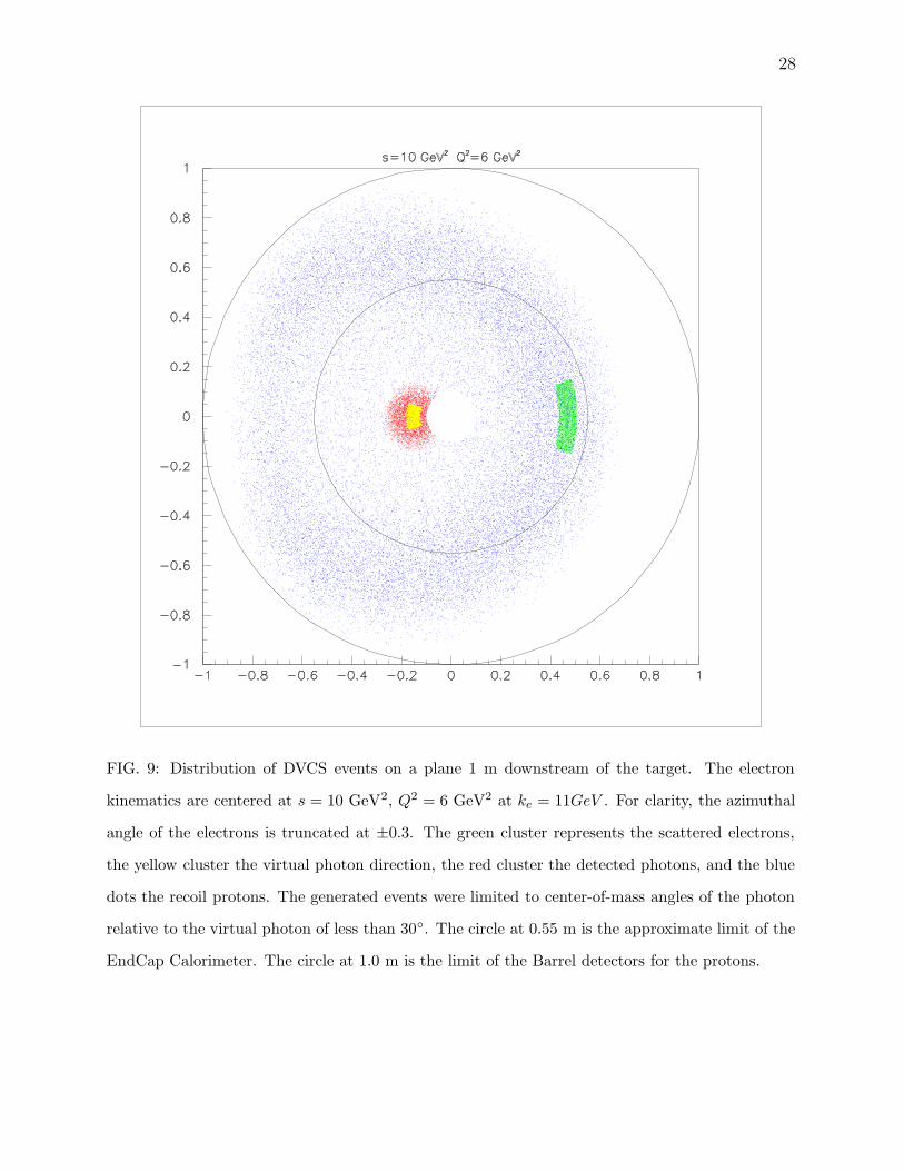
Fig. 9 illustrates the DVCS kinematics at s = 10 GeV2 and Q2 = 6 GeV2 (xBj = 0.4)
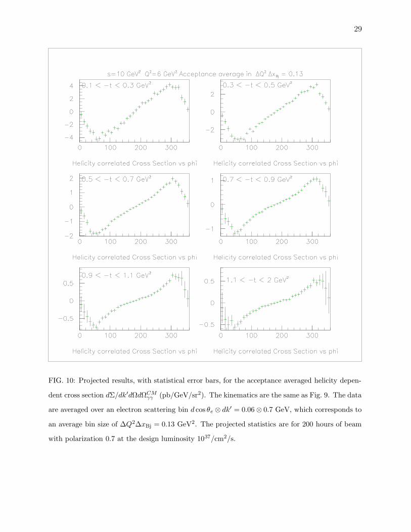
at 11 GeV. In Fig. 10 we show projected results for the helicity correlated cross section at
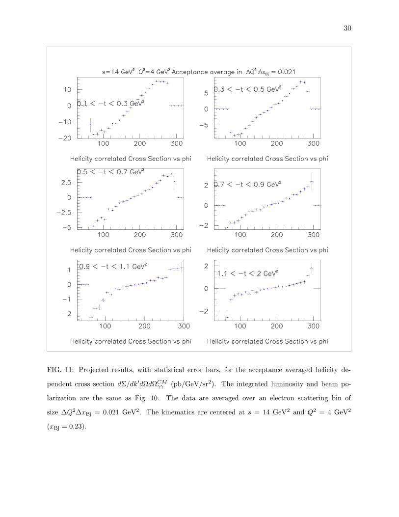
this kinematic point. In Fig. 11 we show projected results for the helicity correlated cross
section at s = 14 GeV2 and Q2 = 4 GeV2 (xBj = 0.23). The suppression of the signal near
φ = 0, 360 is an acceptance effect from the small central angle (−5) of the virtual photon
direction.
B. Charmonium
Coherent J/Ψ production is the cleanest observable we have for accessing the gluon
GPDs. The existing, exclusive J/Ψ photo-production data near threshold are consistent
with a 2-gluon exchange model. At low Q2, this detector will produce 100 tagged J/Ψ per
26
-1 -0.8 -0.6 -0.4 -0.2 -0 0.2 0.4 0.6 0.8 10
5
10
15
20
25
30
-1 -0.8 -0.6 -0.4 -0.2 -0 0.2 0.4 0.6 0.8 10
5
10
15
20
25
30
Missing Energy NStar Events
FIG. 8: Reconstructed missing energy ke + M − k′ − q′ − Ep in electron scattering kinematics of
Fig. 9. The stacked histograms are from bottom to top: (Red) ep → eN ∗γ events with the proton
detected in the EndCap; (Green) N ∗ events with the proton in the Barrel; (Yellow) ep → epγ
exclusive events with the proton detected in the EndCap; and (Blue) exclusive events with the
proton in the Barrel. The reconstruction algorithm is described in the text.
hour in the reaction H(e, e′p)J/Ψ. With at least 50% acceptance for each di-lepton decay
channel, there will be 3 counts per hour in each di-lepton channel H(e, e′pl+l−). Additional
studies are needed to establish the resolution of J/Ψ reconstruction.
C. Conclusions
We have demonstrated that a very powerful detector can be built for deeply virtual
exclusive reactions.
27
X. BIBLIOGRAPHY
[1] D. Muller, et al., Fortsch. Phys. 42, 101 (1994).
[2] X. Ji, Phys. Rev. Lett. 78, 610 (1997).
[3] A. V. Radyushkin, Phys. Lett. B 380, 417 (1996).
[4] J. C. Collins, L. Frankfurt and M. Strikman, Phys. Rev. D 56, 2982 (1997).
[5] M. Diehl, T. Gousset, B. Pire and J. P. Ralston, Phys. Lett. B 411, 193 (1997).
[6] A. V. Belitsky, D. Muller and A. Kirchner, Nucl. Phys. B 629, 323 (2002).
[7] M. Burkardt, Phys. Rev. D 66, 114005 (2002).
[8] M. Diehl, Eur. Phys. J. C 25, 223 (2002); [Erratum-ibid. C 31, 277 (2003)].
[9] A.V. Belitsky, X. Ji and F. Yuan, Phys. Rev. D 69, 074014 (2004).
[10] E. R. Berger, M. Diehl and B. Pire, Eur. Phys. J. C 23, 675 (2002).
[11] R. Y. Zhu, D. A. Ma, H. B. Newman, C. L. Woody, J. A. Kierstad, S. P. Stoll and P. W. Levy,
Nucl. Instrum. Meth. A 376, 319 (1996).
[12] S. Bachmann, A. Bressan, L. Ropelewski, F. Sauli and D. Mormann, Nucl. Instrum. Meth. A
433, 464 (1999).
28
FIG. 9: Distribution of DVCS events on a plane 1 m downstream of the target. The electron
kinematics are centered at s = 10 GeV2, Q2 = 6 GeV2 at ke = 11GeV . For clarity, the azimuthal
angle of the electrons is truncated at ±0.3. The green cluster represents the scattered electrons,
the yellow cluster the virtual photon direction, the red cluster the detected photons, and the blue
dots the recoil protons. The generated events were limited to center-of-mass angles of the photon
relative to the virtual photon of less than 30. The circle at 0.55 m is the approximate limit of the
EndCap Calorimeter. The circle at 1.0 m is the limit of the Barrel detectors for the protons.
29
FIG. 10: Projected results, with statistical error bars, for the acceptance averaged helicity depen-
dent cross section dΣ/dk′dΩdΩCMγγ (pb/GeV/sr2). The kinematics are the same as Fig. 9. The data
are averaged over an electron scattering bin d cos θe ⊗ dk′ = 0.06 ⊗ 0.7 GeV, which corresponds to
an average bin size of ∆Q2∆xBj = 0.13 GeV2. The projected statistics are for 200 hours of beam
with polarization 0.7 at the design luminosity 1037/cm2/s.
30
FIG. 11: Projected results, with statistical error bars, for the acceptance averaged helicity de-
pendent cross section dΣ/dk′dΩdΩCMγγ (pb/GeV/sr2). The integrated luminosity and beam po-
larization are the same as Fig. 10. The data are averaged over an electron scattering bin of
size ∆Q2∆xBj = 0.021 GeV2. The kinematics are centered at s = 14 GeV2 and Q2 = 4 GeV2