SPE 49522 Acid/Sour Gas Management in the Petroleum Industry A.K.M. Jama/uddin, 0.8. Bennion, F.B. Thomas, Hyca/ Energy Research Laboratories Ud. M.A. Clark, University of Ca/gaty ~ 1_. Society d ~ ~ 1Na~- ~"'~.""HIu 0-. ~ ~ ~ .. ~ 181 ft HIu c.WIi. U.A.E.. 11-14 ~ 1-. 1Na p8p« - 88I8d8d far ~ by .. SPE ~ Cam1II88Io1'-ing -- d ~ ~ -J..-I..,. ~ ft 8\ ~ ~ br .. do(.). Ccw8U d .. ~ - ~ Iwv8 .a ~ f8Wi8W8d br .. Society d ~ ~.. - ~m~ br ~.). Tt8m81i11, - ~ dO8 .a ~ I8ft8d ." POIIion d .. SodIIy d ~ ~ « - -m... ~ ~ . SPE II88IWIOI - ~ m ~ -- br ~ c-.. d .. SodIIy d pw ~ P. ..8m. m ~ iI~m8\~d.anaw""~~ ~nwy-.ab8 ~ Tt8 ~ ~ ~ ~ ad;- .AJec ~.; d wh88 .. br ~ .. ~ - ~ ~ ~ SPE. P.O. b 8333838, ~ ~.. TX 1~~ U.S.A.. f8X01-214-M2-8C35. Abstract Due to decreasing world demand for elemental sulphur, the economics of recovering sulphur from sour natural gas has become unfavorable. At the same time, air emission standards and regulations are becoming ina'eaSingiy stringent, increasing the economical strain on oil and gas companies producing sour natural gas. Hydrocarbon producing companies are in search of environmentally-friendly and cost-effective methods for dealing with acid gas, which is produced in association with sour natural gas. In recent years. compressed acid gas re-injection into a porous formation has emerged as a viable alternative to sulphur recovery with the added advantage of eliminating air emissions. As an alternative, some operators also solubilize the sour/acid gas into disposable formation water and dispose acid water into porous formation. In addition, to take advantage of high solubility of acid/sour gas into light hydrocarbon solvent, some operators are also injecting light hydrocarbon solvent containing acid/sour gas into the depleted oil leg as a miscible flood enhanced oil recovery (EOR) technique. Laboratory tests and results will be presented in this paper which illUSb'ate the pros and cons of all these alternative processes to manage the produced acid/sour gas in the petroleum industry. be "sweetened"to selectively remove the acid gas components beforethe gas canbetransported and sold for commercial use. Amongthe sweetening processes, amine extraction process is the most commonly used process in die petrolewn industry. The sweetening process results in die production of acid gas-free "sales" gas,and a rich waste gas stream consisting of virtually pure carbon dioxide (COJ and hydrogen sulphide ~S). The waste gas streamis commonly referredto as acid gas. The economics of recovering sulphurfrom acid gas has become unfavorable because of decreasing world demand for elemental sulphur.Air emission standards and regulationsare becomingincreasingly stringent, increasing die need for anenvironmentally-friendly and cost-effective methodsfor dealing with the acid gas streams. There arevarious alternatives to dealwith the acid gasmixtures. These alternatives are: . Injection of compressed acid gas into the porous formation. . Dispose acid gaswith disposable fonnation water. . Solubilize acid gas into light hydrocarbon solvent and inject the solvent containing acid gas component into the depleted reservoir asa miscible flood enhanced oil recovery (EOR) technique. Acid gas compression and re-injection into depleted resuvoirs or disposal zones, similar to produced water disposal, is a viable alternative to traditional sulphur recovery processeswith the added advantagesof reducing greenhouse gas emissions and providing pressure supportfor producingreservoirs. 1-4 Acid gas recovered from die amine process contains water, and hence, proper strategic design is essential to address ilie issue of whether an acid gas stream needs dehydration or not The appearance of a free liquid water phasedue to changes in temperature and pressure conditions can cause significant operating problems (i.e. compressor damage,corrosion, hydrates formation, etc.). Currently, most injection schemes include dehydration facilities to ensure ilie absence of free Introduction Sournaturalgases areproduced aseitherfreegas or as liberated solution gasfrom sour oil. These gases must
Transcript
SPE 49522
Acid/Sour Gas Management in the Petroleum Industry
A.K.M. Jama/uddin, 0.8. Bennion, F.B. Thomas, Hyca/ Energy Research Laboratories Ud.M.A. Clark, University of Ca/gaty
~ 1_. Society d ~ ~
1Na~- ~"'~.""HIu 0-. ~~ ~ .. ~ 181 ft HIu c.WIi. U.A.E.. 11-14 ~1-.1Na p8p« - 88I8d8d far ~ by .. SPE ~ Cam1II88Io1'-ing-- d ~ ~ -J..-I..,. ~ ft 8\ ~ ~ br .. do(.). Ccw8Ud .. ~ - ~ Iwv8 .a ~ f8Wi8W8d br .. Society d ~~.. - ~m~ br ~.). Tt8m81i11, - ~dO8 .a ~ I8ft8d ." POIIion d .. SodIIy d ~ ~ «- -m... ~ ~ . SPE II88IWIOI - ~ m ~ --br ~ c-.. d .. SodIIy d pw ~ P. ..8m. m ~iI~m8\~d.anaw""~~ ~nwy-.ab8~ Tt8 ~ ~ ~ ~ ad;- .AJec ~.; d wh88 ..br ~ .. ~ - ~ ~ ~ SPE. P.O. b 8333838,~ ~.. TX 1~~ U.S.A.. f8X01-214-M2-8C35.
AbstractDue to decreasing world demand for elemental sulphur,the economics of recovering sulphur from sour naturalgas has become unfavorable. At the same time, airemission standards and regulations are becomingina'eaSingiy stringent, increasing the economical strainon oil and gas companies producing sour natural gas.Hydrocarbon producing companies are in search ofenvironmentally-friendly and cost-effective methodsfor dealing with acid gas, which is produced inassociation with sour natural gas.
In recent years. compressed acid gas re-injectioninto a porous formation has emerged as a viablealternative to sulphur recovery with the addedadvantage of eliminating air emissions. As analternative, some operators also solubilize the sour/acidgas into disposable formation water and dispose acidwater into porous formation. In addition, to takeadvantage of high solubility of acid/sour gas into lighthydrocarbon solvent, some operators are also injectinglight hydrocarbon solvent containing acid/sour gas intothe depleted oil leg as a miscible flood enhanced oilrecovery (EOR) technique. Laboratory tests and resultswill be presented in this paper which illUSb'ate the prosand cons of all these alternative processes to managethe produced acid/sour gas in the petroleum industry.
be "sweetened" to selectively remove the acid gascomponents before the gas can be transported and soldfor commercial use. Among the sweetening processes,amine extraction process is the most commonly usedprocess in die petrolewn industry. The sweeteningprocess results in die production of acid gas-free"sales" gas, and a rich waste gas stream consisting ofvirtually pure carbon dioxide (COJ and hydrogensulphide ~S). The waste gas stream is commonlyreferred to as acid gas.
The economics of recovering sulphur from acid gashas become unfavorable because of decreasing worlddemand for elemental sulphur. Air emission standardsand regulations are becoming increasingly stringent,increasing die need for an environmentally-friendly andcost-effective methods for dealing with the acid gasstreams. There are various alternatives to deal with theacid gas mixtures. These alternatives are:. Injection of compressed acid gas into the porous
formation.. Dispose acid gas with disposable fonnation water.. Solubilize acid gas into light hydrocarbon solvent
and inject the solvent containing acid gascomponent into the depleted reservoir as a miscibleflood enhanced oil recovery (EOR) technique.Acid gas compression and re-injection into depleted
resuvoirs or disposal zones, similar to produced waterdisposal, is a viable alternative to traditional sulphurrecovery processes with the added advantages ofreducing greenhouse gas emissions and providingpressure support for producing reservoirs. 1-4
Acid gas recovered from die amine process containswater, and hence, proper strategic design is essential toaddress ilie issue of whether an acid gas stream needsdehydration or not The appearance of a free liquidwater phase due to changes in temperature and pressureconditions can cause significant operating problems
(i.e. compressor damage, corrosion, hydrates formation,etc.). Currently, most injection schemes includedehydration facilities to ensure ilie absence of free
IntroductionSour natural gases are produced as either free gas or asliberated solution gas from sour oil. These gases must
2 ACID/SOUR GAS MANAGEMENT IN THE PETROlEUM INDUSTRY SPE 49522
in the injection gas is considerably greater than dlisvalue. In other instances, the H2S content in the acidgas streams are seen to be lower as well (in die range of100/0 and the remaining component is COJ.
Injection of Compressed Acid Gas into the PorousFormation. Sour natural gases are sweetened byremoving H2S and CO2 by absorption with aregenerative solvent in an amine plant. The acid gasmixture of H2S, CO2, and a small amount of lighthydrocarbons leaves the sweetening unit saturated withwater at the amine still conditions of low pressure andhigh temperature. The gas mixture is then compressedin 3 to 4 stages. After each stage, the gas mixture iscooled, without entering the two-phase region.Condensed water is removed after each stage. Afterthe last stage, the mixture travels down the pipeline intothe disposal well. Ideally at the fmal compressordischarge pressure, the mixture will be supercritical.Further cooling in the pipeline will increase the densitywithout a phase change, increasing the hydrostatic headof fluid in the well and reducing the required injectionpressure. The operator must ensure d1at the mixturedoes not cool below its water saturation temperature,especially in the hydrate region, to avoid corrosion andhydrate plugging of the pipeline and wellbore.
Corrosion and hydrates may occur when the gas issaturated with water. Due to the safety hazardassociated with acid gas equipment failure, mostinjection schemes currently include dehydrationfacilities to ensure the acid gas is undersaturatedthroughout the system. Unfortunately, dehydrationfacilities and stainless steel comprise a major portion ofthe capital cost of re-injection facilities. Methanolinjection is an option to combat corrosion and hydratefonnation, but can significantly increase operating
expenses.Although there is little experimental data on acid
gas mixture, the solubility of water in pure H2S andCO2 lead to some interesting hypotheses. The ability ofthe pure c0mp01Dlds to hold water in the vapor phasedecreases as the pressure increases up to about 3000kPa (400 psi) for H2S and 6000 kPa (900 psi) for CO2.At higher pressures dte water holding capacity of thegases increases, corresponding to a higher waterabsorption capacity in dte liquid phase or dense phasecompared to the vapor phase. In both cases, inaeasingthe temperature allows more water to be absorbed inthe gas phase. Small amounts of methane substantiallyreduce the water absorption ability of both components.
It is assumed d1at solubility of water in the gasmixtures mimics the trend of dte individualcomponents, then a minimum water holding capacityexists at some pressure. I In a re-injection facility, over
each compression stage, dte pressure and temperature
water in die system and reduce corrosion and hydrateconcerns. Dehydration facilities comprise a majorportion of die capital cost of re-injection facilities.Alternatively, stainless steel materials and med1anolinjection are used to combat corrosion and hydrateformation conditions. However, diis alternative is alsoexpensive and poses significant operating problems. Analternative and cost-effective approach would be tokeep die water in die vapor phase throughout theinjection circuit, eliminating die need to dehydrate.
To design an optimized injection strategy widioutdehydrating the acid gas, detennination ofthermodynamic properties (i.e. water content,dewpoint, bubble point, and hydrate points) of die acidgas is necessary. The system may also be designed toinject die mixture as a dense phase, above die criticalpoint, reducing die required injection pressure andhorsepower requirement due to die hydrostatic head ofdie colwnn of fluid in die injection wellbore. Thehydrate curve information will ensure diat the systemnever enters die hydrate region, reducing die risk of
pipeline plugging.An alternative approach is to solubilize die acid gas
in produced or source water in a high pressurecontacting tower on the surface, followed bysubsequent injection of die sour water.s Anunderstanding of die solubility of die injected gas or in-situ water phase is essential in order to quantify diespeed of migration of die injected gas (in a directinjection scheme) and to design the contactingapparatus and determine volumes of water required toeffect disposal in a sour water disposal scenario.
Anodier approach is to solubilize acid gas into lighthydrocarbon solvent (taking advantage of highsolubility of acid gas into light hydrocarbon solvent),and subsequently, use die light hydrocarbon solventcontaining acid gas into die depleted hydrocarbonreservoir as a miscible flood enhanced oil recovery
(EOR) tedmique.Experimental tests and results of various processes
are discussed in this paper. In addition, advantages anddisadvantages of all diese options are also discussed.
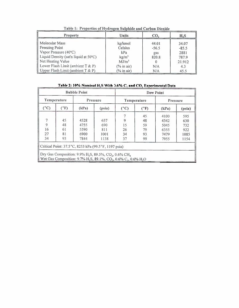
Characteristics of Acid Gas StreamsA summary of basic characteristics of acid gascomponents are summarized in Table 1.6.7 As seen inthe table, bodt gases have diatomic structme andexhibit high propensity for solubilizing in both aqueousand hydrocarbon solutions, a fact which can be used toour advantage in some disposal operations.Composition ofdte injected acid gases can vary widelyand is a direct function of the acid gas content of theoils/gases which are acting as the feedstocks for thesweetening process. In general, most acid gas blendscontain at least 4Q8/. H.,S and often dte fraction ofHzS
increase and after each compression stage die gas iscooled. Initially, die water holding capability of die gasdecreases from stage to stage, until d1e minimum waterholding capacity is reached. Ifdle condensed water isremoved at this point. the gas will be undersaturatedwidl water throughout die rest of compression.Stainless steel will not be required in the compressorsor coolers after die second last stage. If dietemperature of die compressed gas does not drop to thenew water saturation temperature in the pipeline orwellbore, dehydration can be eliminated and stainlesssteel materials and methanol injection will not be
necessary.It is understood that dehydration may not be
completely eliminated due to a particular set ofconditions, for example in an extremely cold climate,die experimental data will still be beneficial. Theoperator will know the inlet water content and theconditions of the lowest water solubility of die system.The glycol contactor tower, regenerator and circulationsystem can then be designed appropriately.
Aldlough experimental data is available for pureH2S and CO20 little work has been done determining diewater content. density, phase behavior and hydrateformation conditions of acid gas mixtures.1-12Currently, estimates of the density, water content andphase behavior of acid gas mixtures are being predictedwith equation of state models, as experimental data isunavailable. The equations can produce considerableerror and result in over or underdesigned facilities.Experimental data results in proper decisions on theequipment and materials required for each particular setof conditions, which can lead to considerable costsavings. In this section of the paper, the results of astudy in which water content. dew point. bubble pointand hydrate formation conditions are presented. Theexample acid gas mixture contains 100/0 H2S/900/o CO2and a minor amount of methane. The mixture wassaturated with water at 2800 kPa and 24OC (400 psiaand 75°F).
Experimental procedure and apparatus. Theapparatus consists of a temperature controlled air bath.a high-pressure cell widl sight glass, a positivedisplacement pump, a gas volume meter, a cooled watertrap, a mass balance and a Hewlett Packard 5890 gaschromatograph (GC). The sight cell has an internalvolume of approximately 80 cm] (5 in]) and amaximum working pressure of 70 MPa at 1500c(10000 psi at 3000F). The 2.5 cm (I in.) dlick sightglass located on the front and back of the cell allowsvisual observation of the cell contents dtroughoutexperimentation. As shown in Figure I, the highpressure sight cell is mounted in the centre of the ovenas are the cylinders containing gas mixtures anddistilled water. The oven can be heated up to 1500c
(3000F) and the temperature is measured and controUedto within % IOC (2°F).
The sight ceU volume and pressure are controlled bythe addition and withdrawal of mercury through a portat the bottom of the sight ceU. Sample fluids arepumped in and out of a port at the top of the cell. Thepump measures volume displacement with a precisionof %0.02 an) (0.001 in2). A dead-weight calibrateddigital pressure gauge is connected to the pump outlet.The oven is connected to a motor via a steel arm. Themotor rotates the ann, rocking the oven and its contentsin a 1800 arc. The mercury in the sight cell agitates thefluids and enhances the fluids and enhances mixingwhen the oven and cell are rocked.
The apparatus is contained in a sour gas laboratory.The lab is continuously flushed with fresh air pumpedin from die ceiling and drawn out of vents located inthe bottom four comers of the room to an incineratorstack. A pem1anent H~ monitor is located close to thefloor, below the apparatus. If the monitor detects 10ppm H~, an alarm sounds outside the sour gas lab andthe incinarator fires up. At 20 ppm the main lights inthe lab shut off and emergency lights flash. Personnelworking in die lab with supplied air breathing apparatus(SABA) may not hear the alarm and the flashing lightsensure their evacuation. The lab is equipped with avideo camera for continuous remote monitoring ofpersonnel performing dangerous work. An "H2S PanicButton" which summons emergency rescue and medicalservices is located immediately outside the sour gas lab.
A gas mixture is synthesized from pure componentsin the laboratory using partial pressures.Concentrations are verified using the GC. The systemis purged and gas is transferred to the sight cell. Thegas in die cell is saturated with water at the desiredtemperature and pressure and allowed to equilibratewhile rocking. At equilibrium. usually reached withina few hours. a stable free water phase should be visiblein the cell. ensuring the gas is fully saturated.
Water content analysis is performed by flashing asample of gas dtrough a valve to a cooled water trapwhile maintaining constant ceU temperature andpressure. The trapped. condensed water is weighed andthe dried gas volume is measured. The average watercontent is obtained over several samples. This methodof water content analysis has not proved reliable due tothe very small quantities of condensed water beingmeasured. The water content data obtained for thisreport can be regarded as accurate only within an orderof magnitude. A control experiment with pure CO2was within 200/0 of accepted values and the averagedifference between samples was %200/0.
ExperimentJ. The objective of this study was toestablish the phase behavior, water content and hydrateconditions of an acid gas mixture saturated at die
compression inlet conditions of2.8 MPa (400 psi) and24°C (75°F). A mixture of 100/0 H2S and 900/. CO2was prepared. A small amount of CH. was added andthe exact composition verified with dte OC. Themixture was saturated widt water at 2.8 MPa (400 psi)and 24 °C (75°F). After several hours of rocking, dteaverage water content was detennined.
Several isodtenns were obtained to establish thephase envelope. The cell temperature was set andallowed several hours to equilibrate. The cell mercuryvolume was increased incrementally, resulting in 15-30psi pressure steps. Transient and stabilized phasebehavior was observed and recorded. The change inmercury volume was recorded as a function ofpressure. At pressures close to dte dew and bubblepoints, dte volume/pressure increment was reduced. Bytaking a series of data points immediately above andbelow the appearance and disappearance of the two-phase region, the dew and bubble points wereestablished.
Isobaric cooling experiments were perfonned toestablish the hydrate fonnation conditions for this acidgas/water mixture. The oven temperature was raised to50°C (122 oF) and dte gas was pressurized to between9000 kPa (1305 psia) and 17700 kPa (2567 psia) andallowed to stabilize. Since the gas was saturated widtwater at 2800 kPa (400 psia) and 24 °C (75 oF) and dtewater content was not changed as the temperature andpressure were raised, the gas was undersaturated at dteconditions of high temperature and pressure. Thetemperature was dten reduced in 1.6 °C (3 OF) stepsevery 30 to 45 minutes until a hydrate was visuallyobserved in dte cell.
The hydrate fonnation temperature measured in thismanner differs from dte traditional hydrate temperatureobtained by cooling gas in contact widt a liquid waterphase. When liquid water is present, hydrate fonnationis predicted to occur at elevated temperatures in dteorder of 20°C (68°F) at 9000 kPa (1305 psia). Whendte gas is not in contact widt a water phase and isundersatw'ated, hydrates cannot fonD until dtetemperature drops sufficiently dlat dte gas can nolonger bold all the water in solution and wfreew water isavailable for dte fonnation of hydrates. Hydrates fonDpreferentially to a liquid water phase, since dte gas isalready below its satmated hYdratetem perature at theseconditions.
Res"lts, observations and discussion. As recordedin Table 2, dew points were observed at 7°c/41 00 kPa,9°C/4342 kPa, 15°C/5045 kPa, 26°C/6355 kPa,34 °C/7479 kPa and 37°C/7955 kPa. Bubble pointsw~ observed at 7°c/4528 kPa, 9°C/4755 kPa,16°C/55 10 kPa, 27°C/6900 kPa and 34°cn844 kPa.
Above 37.5°C (99.5 OF), a stable two-phase regionwas not observed. Some droplets, and elongated
bubbles appeared during a volume/pressure change andwhile the system was stabilizing, but upon reachingequilibrium, the system was single phase at all
pressures.At 37.5°C (99.5 oF) and 8253 kPa (1197 psia), the
critical point was observed. At all other temperaturesthe contents of the cell were clear and colorless in thevapor, liquid and two-phase regions. In the criticalregion, a small change in pressure (3-5 psi) resulted inthe entire cell contents becoming a murky, grey cloudand then stabilizing out into a variety of shades ofyellow. Above 8303 kPa (1205 psia) the contents weresingle phase, clear and colorless. At about 8274 kPa(1200 psia), the see-through single phase took on aslightly yellow tint. At the critical point of 8253 kPa(1197 psia), two phases appeared with an indistinctthick yellow interface, a darker yellow color at d1ebottom of the cell and a lighter yellow color on top. At8212 kPa (1191 psia) the bottom half of the cell was adistinct dark orange liquid and the top half a colorlessvapor. At 8198 kPa (1189 psia) the liquid phase fadedto yellow and below 7957 kPa (1154 psia) the cellcontents were again a colorless single phase.
In Figure 2, the calculated equation of state phaseenvelope is plotted along with the experimental data.The widths of the two phase envelopes are similar, butthe calculated envelope falls below and to the left ofthe experimental data. The calculated critical pointoccurs at 34.9 °C and 7633 kPa (94.8 of, 1107 psia),2.6°C and 620 kPa below the experimentallydetermined critical point of 37.5°C and 8253 kPa(99.5°F, 1197 psia). The deviations between actualand calculated phase behavior emphasize theimportance of obtaining an experimental data set foracid gas mixtures. The equation of state was regressedto fit d1e phase behaviour data obtained experimentally.The regressed curves and critical point match themeasured data within the experimental error. Themodified equation of state allows some extrapolation todifferent conditions, but experimental verification willbe necessary until more data becomes available and ageneral regression is completed.
The Sa11D'ated water content of the gas mixtW"C at2860 kPa and 24°C (415 psia and 75°F) over foursamples was measured to be 0.6 mole percent or 270 Ibwater/MMSCF. This value is over three times d1evalue that analysis of accepted pure component dataand equation of state calculations predict. Thedifference is attributed to experimental error andreflects on inaccuracies inherent in dte gravimetricwater content measurement.
Figure 3 summarizes dte phase behavior andhydrate formation data obtained for dtis acid gasmixture. The two-phase region can be avoided duringcompression by cooling the gas to a minimum of
SPE 49522 A.KM. JAMALUDOIN. D.B. BENNION. F .B. THOMAS. MA CLARK 5
37.5°C between compression stages. The fluid is inthe supercritical, dense phase above 8253 kPa andabove 37.5°C.
The hydrate formation temperature is below thetraditional hydrate temperature since the gas is not incontact with a liquid water phase. With undersaturatedgas, hydrate fonnation is expected to coincide with dtewater saturation temperature. In this study, hydrateswere observed at temperatures above the expectedwater saturation temperature of the gas. At 9000 kPa(1305 psia) and 17700 kPa (2567 psia) predictionsbased on pure component water saturation data indicatethe gas will be saturated at approximately -9°C (15°F)and -18°C (0 oF), while hydrates were observed at -2 °C(28°F) and 8°C (46°F). The difference can beattributed either to experimental error or theinaccuracies inherent in predicting mixture saturationtemperatures from pure component data. In either case,since the observed hydrates occurred at highertemperatures than expected, a conservative designwould not require dehydration of the gas unless thetemperature in the pipeline or wellbore dropped belowthe observed hydrate formation temperature.
Disposal of Acid Gas with DisposableFonnation WaterSour water injection has advantages and disadvantagesin comparison to direct injection. The technique resultsin better containment of the sour gas as it is dissolvedin the injected aqueous phase and, excepting diffusiveforces which act very slowly in porous media, the sourwattt moves only as the injected phase spreads into thereservoir. This also lessens safety concerns with respectto rate of release and volume of release in the event ofblowout of a sour disposal well. Compression costs arereduced, as the effluent is pumped down the well as aliquid phase using conventional equipment (withappropriate corrosion inhibition). Disadvantagesinclude concerns about corrosion in the surface andinjection equipment, hydrate in the contactingequipment, cost and safety of the surface contactingequipment, and the fact that the phase behaviour of thesour water must be precisely detem1med to ensure thatsour gas is not liberated from solution as temperatureincreases as the fluid is heated by contact with thefonnation. The water-contacting process also suffersfrom the fact that it is not a perfect method for removalof acid gases and preferentially tends to adsorb H2Sover CO2. A relatively large volume of water is alsorequired to dissolve an acid gas stream of anyappreciable volume. The technique can still beadvantageous in systems where a large volume ofproduced water is available and must be disposed inany event, and can be used as a technique to extract alarge fraction of the sour gas component from a rich
acid gas Sb'eam. This reduces the cost. volume and H2Scontent of the remaining residual gas whichsubsequently will be processed by more conventionalmeans.
Solubility of acid gases in aqueous solution is afunction of the following parameters:. Acid gas composition. Contacting pressure. Contacting temperature. Water salinity
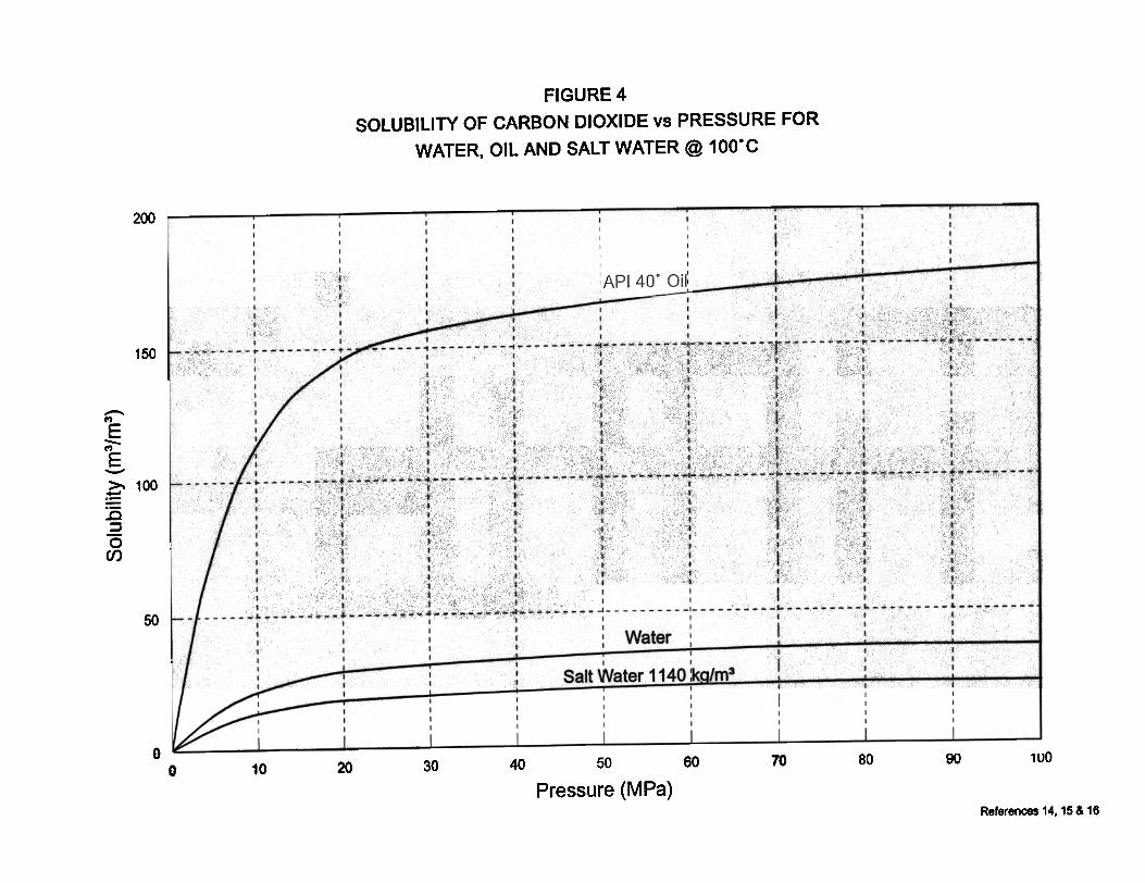
Solubility increases with increasing H2Sconcentration and increasing pressure (althoughsolubility generally levels out near the critical pressureof the mixture (about 7000-10000 kPa). Solubility isreduced by inaeasing temperature and increasingsalinity of the contacted water. Figure 4 provides anillustration of the solubility of pure carbon dioxide infresh and salt water at various pressures at 100°C.There are virtually no published data on the solubilityof mixtures of acid gases in water. Table 2 provides asummary of some limited selected solubility dataavailable for different concentrations of acid gases atvarioustem perature and pressure contacting conditions.Detailed experimental solubility studies should beconducted prior to any acid gas injection study. Thiswill quantify the compatibility and expected solubilityof the target acid gas stream in the specific aqueousphase present in the reservoir or contemplated for co-
injection.Problems may be associated with solubility of
hydrogen sulphide into water. Water solutionscontaining H2S are not stable and reaction withadsorbed oxygen can cause the precipitation ofelemental sulphur\) and turbidity. This may result inplugging of the injection zone by the suspended solidprecipitate. The turbidity can be reduced by filtration orstabilized with various inhibitors (ie. glycol), but bothtechniques may increase the cost of the injectionoperation significantly thus reducing the economicviability of d1e sour water injection operation.
Solubilize Acid Gas into Light HydrocarbonSolvent and Inject the Solvent Containing Acid GasComponent into tbe Depleted Reservoir as aMiscible Flood Enhanced Oil Recovery (EOR)Technique. Rich acid gases exhibit extreme solubilityin liquid hydrocarbons at elevated pressures (gas-oilratios of acid gases in hydrocarbons. particularly lightcondensates. can be in excess of300 m3/m3). Solubilityof pure CO2 in 40° API gravity oil at 100°C isprovided in Figure 4. Many potential injection zonescontain a residual mobile or immobile liquidhydrocarbon saturation. This would include depletedoil reservoirs. transition zones containing an immobileoil saturation. watertlooded zones at a residual oil
condensate reservoirs or some gas reservoirs whichhave been created by gas migration over geologicaltime into previously oil bearing strata. As the liquidsaturation increases in value, it still remains below theirreducible value and hence is not mobilized, butexpands and occludes space previously available forgas to be injected. The end result can be a significantreduction in gas phase injectivity if the configuration ofthe gas phase relative penneability curve is very steepat low liquid saturation values. Figure 6 provides anillustration of this phenomena.
This problem is very difficult to diagnose withoutdirect field or lab testing. Conventional gas-liquidrelative penneability curves can provide some insight,but the parameters and configuration of nonnal gas-liquid relative penneability curves are generallysignificantly altered when considering an acid gas-oilor acid gas-water system. Dissolution of the acid gas inthe liquid phase significantly reduces its viscosity (byan order of magnitude or more for some hydrocarbonliquid systems) and also can substantially reduceinterfacial tension between the gas and liquid phases.
Potential Side Benefits. Acid gas re-injection mayhave potential side benefits in addition to the directdisposal of unwanted sour gas. Some of these factorshave been alluded to previously, but will now bediscussed in greater detail. They include:
Potential stimulative nature caused by carbonatedissolution. In the absence of adverse precipitationeffects and dissolution induced fmes mobilization andplugging, long-term acid injection may actuallyimprove injectivity in some disposal wells due to lowpH induced dissolution effects.
Desiccation. In most direct acid injection projects,the injected acid gas will have been dehydrated tominimize hydrate problems at surface. Due to higherdownhole temperatures, hydrate formation willl&elynot be problematic, but the dry nature of the injectiongas may result in a gradual desiccation of the trappedirreducible or connate water saturation from the regionadjacent to the injection zone. This is analogous to aphenomenon which often occurs during injection ofconventional dry gas into gas storage reservoirs. Thereduction in initial water saturation can cause anincrease in injectivity due to a lessening of adverserelative permeability effects associated with thepresence of the initial water saturation in the porousmedia. This effect may also be damaging if the insituwater being desiccated is highly saturated with solublesalts (for example, in a typical deep carbonateformation). Desiccation of fluid by the injection gasresults in precipitation of these soluble salts within thepore system which may have a counteracting effect onthe expected increase in penneability due to water
saturation, depleted gas reservoirs containing an initialirreducible or sub-irreducible oil saturation, anddepleted retrograde condensate gas zones containing atrapped irreducible or sub-irreducible criticalcondensate saturation. Two potential concerns arisewith respect to the contact of these hydrocarbon liquidswith the acid gas as follows:
Compatibility. Many oils may de-asphalt whencontacted with diatomic gases such as CO2 and H2S.The precipitation of granular solid asphaltenes can leadto plugging of the pore system and restricted injectivityin the near wellbore region. If injection into a zonecontaining liquid hydrocarbons is contemplated,detailed compatibility testing should be conductedbetween the live hydrocarbon liquid and the proposedinjection gas over the range of expected downholeinjection conditions to ensure that destabilization ofasphaltenes from the liquid hydrocarbon phase does not
occur.Swelling. Due to the extreme solubility exhibited
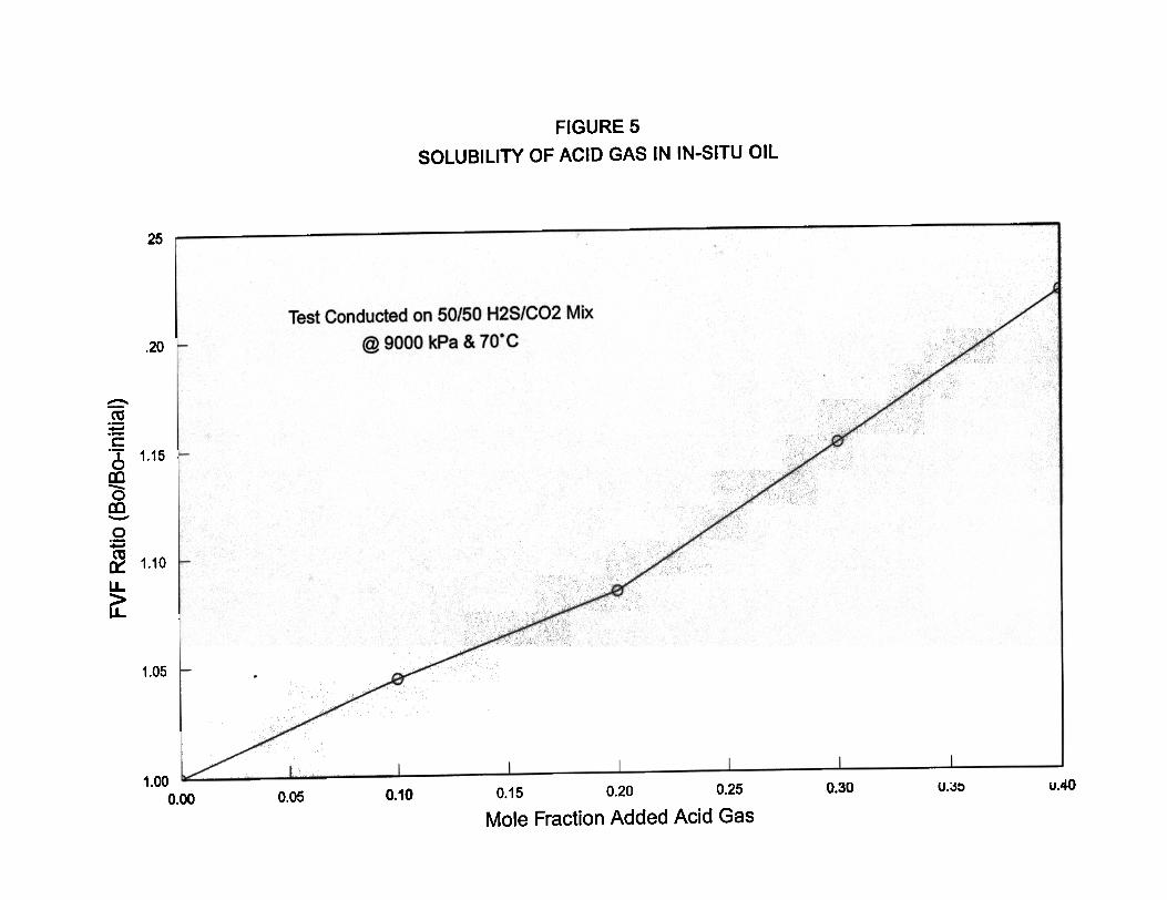
by rich acid gases in most hydrocarbons a largeformation volume factor increase (expansion of the sizeof the liquid hydrocarbon phase) occurs when the acidgas contacts the insitu oil. If pressure is sufficient, theacid gas may actually be miscible with the insitu crudewhich will result in miscible displacement of theresidual oil saturation away from the wellbore area,potentially creating an advantageous increase in relativepermeability to the injected acid gas and an increase ininjectivity. In many situations, the composition of theacid gas, liquid hydrocarbon gravity and downholetemperature and pressure conditions are not conduciveto the establishment of miscibility. In this situation, aportion of the injection gas is absorbed into the trappedliquid hydrocarbon phase, causing a large increase information volume factor of the oil. Figure 5 provides apressure-composition diagram for a typical insituretrograde condensate phase with a molecular weight ofapproximately 110 when contacted with a 50%H2S/500/o CO2 acid gas stream at 10000 kPa and 60 °C.It can be seen at the saturation point (ie. point wherethe saturation pressure of the liquid is equivalent to theinjection pressure of 12000 kPa representing themaximum degree of swelling expected to occur) that anincrease in condensate volume of over 27% occurs dueto solubility effects.
If the expanded oil saturation is already at theirreducible level, the problem may not be significant.When the oil saturation expands, it is basically akin toincreasing the oil saturation, and the portion of theincreased liquid hydrocarbon saturation in excess of theirreducible value should be mobilized and displaceddeeper into the formation. Problems may occur if theoriginal oil saturation is relatively small and is at asubirreducible level. This often occurs in depleted gas
References
Wichert, E. and T. Royan, "Sulphur Disposal byAcid Gas Injection," SPE 35585, GasTechnology Conference, Calgary, Alberta,Canada, May 1996.
saturation removal, depending on the location of the re-precipitation within the pore system.
limited Or Fun Miscibility with In-situ Oil Mostacid gas streams represent excellent miscible injectionsolvents (from a phase behaviour point of view) andvery low or zero interfacial tension can be obtainedwith these gases with many oils at relatively lowpressures. This makes these gases potential EORinjectant candidates for the miscible displacement ofoils (which are generally in and of themselves alreadysour). Due to the supercritical nature of the gas, actualvolume available for injection is usually too small to bean effective consideration for voidage replacement foran EOR process. Situations do exist. however, wherethe rich acid gas, extracted from produced solution gasfrom a large oil reservoir or directly from a sour gasreservoir, could be used to miscibly inject into adjacentsmaller oil pools or isolated zones of the source oilpool. Detailed lab and numerical studies would berequired in this situation to confinn miscibility with theinsitu crude, pressure required to maintain low1FT/miscibility and potential compatibility concernswith the gas-crude system and injectivity issues asdiscussed previously. Contingency plans for prematureultra-sour gas breakthrough at a producing well are also
a necessity in this situation.
1.
Keushnig, H., "Hydrogen Sulfide - If You Don'tLike It, Put It Back," Journal of CanadianPetroleum Technology, 34(6), June 1995, 18-20.
2.
Longworth, H.L., G.C. Dunn and M.Semchuck,"Underground Disposal of Acid Gas in Alberta,Canada: Regulatory Concerns and CaseHistories," SPE 35584, Gas TechnologyConference, Calgary, Alberta, Canada, May1996.
3.
Clark, M.A., W.Y. Svrcek, W.D. Monnery,A.K.M. Jarnaluddin. D.B. Bennion, F.B.Thomas, E. Wichert, A. E. Reed, and D.J.,Johnson, "Designing and Optimized InjectionStrategy for Acid Gas Disposal widtoutDehydration," paper presented at dte 11mAnnual Convention of dte Gas ProcessorsAssociation, Dallas, Texas, March 16-18, 1998.
4.
Duckworth, G.L., D. Kopperson, S. Home, G.Kohn, D. Romansky, and C. ChaD, "Dispoal ofAcid Gases with Oilfield Produced Water,"paper presented at the 7~ Annual Conventionof the Gas Processors Association, Dallas,Texas, March 16-18,1998.
5.SummaryAcid gas or water injection has proven to be a viabletechnology for the disposal of large volumes of wasteacid gas. For compressed acid gas injection, either asa disposal or miscible solvent, the operating companymust avoid the two-phase region during compression.Water condensation and hydrate formation in the post-compression equipment must be prevented to ensure asafe, cost-effective operation. Experimental data on thewater content, density, hydrate and phase behavior ofacid gas mixtures is therefore necessary. In the case ofthe studied acid gas mixture of 9.90/0 H2S, 89.5% CO2and 0.6% CR., dehydration is not required unless thetemperature drops below 8 °C at 17700 kPa. The two-phase region will be avoided during compression bymaintaining the gas temperature above 37.5 °C between
stages.
AssociationSuppliers
"Natural Gas ProcessorsHandbook," Gas ProcessingOrganization, Tulsa, O.K., 1980.
6.
"Merck Chemical Index, " Ill" Edition. Merck &
Co. Inc., Rahway, N.J., USA, 1983.7.
Song, K. and R. Kobayashi, "Water Content ofCO2 in Equilibrium with Liquid Water and/orHydrates", SPE Formation Evaluation,December 1987,500-508.
8.
Selleck, F.T., L.T. Cam1ichael and B.H. Sage,"Phase Behavior in the Hydrogen Sulfide-WaterSystem", Ind Eng. Chem., September, 1952,44(9),2219-2226.
AcknowledgmentsThe authors would like to thank Union PacificResources Company for permission to publish theexperimental data. The authors also expressappreciation to Vivian Whiting for her assistance in thepreparation of the manuscript and figures.
9.
8 ACID/SOUR GAS MANAGEMENT IN THE PETROLEUM INDUSTRY SPE 49522
Carroll, J.J. and A.E. Mather, "PhaseEquilibrium in die System Water-HydrogenSulfide: ExperimentalDetenn ination of die LL VLocus", Canadian Journal of ChemicalEngineering.,67, June, 1989, 468-470.
10.
Ng, H., D. Robinson and A. Leu, "CriticalPhenomena in a Mixture of Methane, CarbonDioxide and Hydrogen Sulfide", Fluid PhaseEquilibria, 19, 1985,273-286.
Huang. S.. A.D. Leu. H.J. Ng and D.B.Robinson. " The Phase Behavior of two
mixtures of Methane. Carbon Dioxide.Hydrogen Sulphide. and Water". Fluid PhaseEquilibria. 19. 1985. 21-32.
12.
Mussumeci, A., "Computation in Gas HydrateFonnation" , SPE 21112, presented at die SPELatin America Petroleum EngineeringConference, Rio de Janeiro, Oct. 14-19, 1990.
13.
Dodds, W.S. et aI, "CO2 Solubility in Water",Chern. Eng. Data Series 1, 1956, p. 92.
14.
Munjal, P. and P .B. Stuwart, "Solubility ofCarbon Dioxide in Pure Water, Synfuetic SeaWater and Synfuetic Sea Water Concentrates at-5°C to 25°C and 10 to 45 ATM Pressure",Journal of Chemical Engineering Data, 15,1970,67.
IS.
Simon, R. and D. Graue, "GeneralizedCorrelations for Predicting Solubility, Swellingand Viscosity Behavior of CO2-Crude OilSystems", Journal of Petrolewn Technology,Ian 1965, p. 102.
16.
Table 2: 10% Nominal D,S With \ .68/0 C. and CO.. Experimental Data
Dry Gas Composition: 9.90/0 HzS, 89.5%, COz, 0.6% CH.Wet Gas Com sition: 9.7% H 0