AD-A247 742 _D AGARD-7 4 ADVISORY GROUP FOR AEROSPACE RESEARCH & DEVELOPMENT rrr < 7 RUE ANCELLE 92200 NEUILLY SUR SEINE FRANCE C =. AGARD ADVISORY REPORT 274 Validation of Flight Critical Control Systems (Validation des Fonctions Critiques pour le Pilotage) This report has been prepared as a summary of the deliberations of Working Group 09 of the Guidance and Control Panel of AGA RD. - NORTH ATLANTIC TREATY ORGANIZATION S2 -'3 ~7~) 92-06960 __________________, ___ ii nII Im l I~ I I II IIII l - -Published December 1991 . Distbution and Availability on Back Cover
Transcript
AD-A247 742 _D
AGARD-74 ADVISORY GROUP FOR AEROSPACE RESEARCH & DEVELOPMENT
rrr
< 7 RUE ANCELLE 92200 NEUILLY SUR SEINE FRANCE
C =.
AGARD ADVISORY REPORT 274
Validation ofFlight Critical Control Systems(Validation des Fonctions Critiques pour le Pilotage)
This report has been prepared as a summary of the deliberations ofWorking Group 09 of the Guidance and Control Panel of AGA RD.
- NORTH ATLANTIC TREATY ORGANIZATION
S2 -'3 ~7~) 92-06960__________________, ___ ii nII Im l I~ I I II IIII l
- -Published December 1991
.Distbution and Availability on Back Cover
BestAvailable
Copy
AGARD-AR-274
ADVISORY GROUP FOR AEROSPACE RESEARCH & DEVELOPMENT7 RUE ANCELLE 92200 NEUILLY SUR SEINE FRANCE
AGARD ADVISORY REPORT 274
Validation ofFlight Critical Control Systems(Validation des Fonctions Critiques pour le Pilotage) *
Edited by
Mr Gordon Belcher, Mr Duncan E. Mclverand Mr Kenneth .J.Szalai4
'[his report has been prepared as a summary of the deliberations ofWorking Group 09 of thc Guidane and Control Panel of AGA RD.
_ _ North Atlantic Treaty OrganizationOrganisation du Trait6 de I'Allantique Nord
The Mission of AGARD
According to its Charter. the mission of AGARD is to bring together the leading personalities of the NATO nations in the fieldsof science and technology relating to aerospace for the following purposes:
- Recommending effective ways for the member nations to use their research and development capabilities for thecommon benefit of the NATO community;
- Providing scientific and technical advice and assistance to the Military Committee in the field of aerospace research and
development (with particular regard to its military application):
- Continuously stimulating advances in the aerospace sciences relevant to strengthening the common defence posture:
- Improving the co-operation among member nations in aerospace research and development:
- Exchange of scientific and technical information:
- Providing assistance to member nations for :he purpose of increasing their scientific and technical potential:
- Rendering scientific and technical assistance, as requested, to other NATO bodies and to member nations in connectionwith research and development problems in the aerospace field.
The highest authority within AGARD is the National Delegates Board consisting of officially appointed senior representativesfrom each member nation. The mission of AGARD is carried out through the Panels which are composed of experts appointedby the National Delegates, the Consultant and Exchange Programme and the Aerospace Applications Studies Programme. Theresults of AGARD work are reported to the member nations and the NATO Authorities through the AGARD series ofpublications of which this is one.
Participation in AGARD activities is by invitation only and is normally limited to citizens of the NATO nations.
The content of this publication has been reproduceddirectly from material supplied by AGARD or the authors,
This report has been prepared as a summary of the deliberations of Working Group 09 of the Guidance and Control Panel ofAGARD. The terms of reference were approved by the National Delegates Board of AGARD and the objectives of the WorkingGroup were:
(I) To provide guidance to those concerned in the Flight Critical Control System (FCCS) validation, namely system designersand certification authorities.
(2) To identify the areas of research which need to be explored to enable validation of the next generation of FCCS.
The Working Group tried to review all flight critical control system validation activities which had been completed or wereunder active consideration, in Europe and the United States. Detailed technical presentations of these relevant examples weremade to the Working Group for their deliberation. In addition, emerging technologies which could have a significant impact onvalidation of future FCCS. were discussed at length by the members of the Working Group.
The Working Group started work in the fall of 1986 and met at six month intervals up to October 1989. The Group wascomposed of members from France, Germany, Italy. the United Kingdom. and the United States, all of whom were expert inguidance and control, and the validation of FCCS. This report represents the consensus view of the Group. but it should not beconstrued as representing the views or policies of any of the nations, organizations, or individuals represented on the WorkingGroup.
Final editing of the report took place during the last half of 1989 and during 1990 and 1991. The final report was prepared withthe support of the NASA Langley Research Center in the United States. with essential help from Mrs Carolyn Wilt. of theLangley Office of Director for Flight Systems.
Preface
Cc rapport cst un resume des deliberations du groupe de travail No. )9 du Panel AGARD du guidage et du pilotage. Le mandatde cc groupe a e approuv par le Conseil des dlgu~s nationaux de I*AGARD (NDB) et ses objectifs ont 6t les suivants:
(I) De fournir des conseils a la communaute de la validation des syst~mes de commandes de vol critiques (FCCS), c'est i dire,aux ingtnieurs systimes et aux autorit6s de certification.
(2) D'identifier les voies de recherche i suivre pour permetre la validation de la prochaine g6neration de FCCS.
Le groupe de travail s'est donn6 comme objectif de passer en revue toutes les activit6s connues dans le domaine des syst~mes decommandes de vol critiques, qu'il s'agisse de travaux diji accomplis ou de projets i lHtude, et ceci en Europe et aux Etats-Unis.Des presentations techniques d6taill6es de ces exemples pertinent! ont et donn6es au groupe pour leur consideration. Enoutre, des technologies naissantes, susceptibles d'avoir un impact sensible sur la validation de futurs FCCS ont t6 discut~esdans le dtail par les membres du groupe de travail.
Le groupe s'est reuni pour la premiere fois 4 rautomne de l'ann&e 1986 et ensuite i des intervalles de six mois jusqu'en octobre1989. II a et compose de membres de la France. de lAllemagne. de Iltalie, du Royaume-Uni et des Etats-Unis: tous experts
dans le domaine du guidage et du pilotage et de la validation des FCCS.
Ce rapport. s'il repr~sente le consensus d'opinion du groupe. ne doit en aucun cas itre interpreti comme la representation desopinions ou des politiques d'un quelconque pays. organisme ou individu, membre du groupe.
Les travaux de mise en forme difinitive du rapport se sont droul6s pendant la deuxiime semestre de 1989 et courant 1990-199 1. Le rapport definitif a etc 6labore avec le soutien du NASA Langley Research Center aux Etats-Unis. avec notamment la
cooperation de Mine Carolyn Wilt. du bureau du Directeur systimes de vol de Langley.
Working Group 09 Membership
FRANCE UNITED KINGDOM Mr Ray HoodlMrLcBrnMr Gordon Belcher NASA Headquarters
Sextant Avionique Group Technical Manager Wa0Indnn e AvenueSW
Centre Avioflique de Toulouse GEC Avionics Limited Uant .States 4
15 Avenue Didier Daurat Airport WorksUntdSae
BP 43 Rochester. Kent ME 1 2XX M ae .RmgF-3 171)8 Blagnac Cedex United Kingdom Chief, Advanced Development
FrneMr David J. Walker Branch
Mr Alain Coupier Research Manager Wright Research & Development
Labo Genie Logiciel British Aerospace Plc Center
(eat Military Aircraft Division WVRDC/FIGX
2 3 Asenue iaillaumet Brough Wright-Patterson AFB
F-3I1056 Toulouse Cedex North Humberside HU 15 I EQ Ohio 45433-6553
France United KingdomUntdSae
Mr Kenneth J. Szalai
GEFRMANY UNITED STATES Chief. Research Engineering Division
Mr liiuergen Kaul Or Jeremiah F. Creedon P0. Box 273Flugzeuge und Hubschrauhcr NASA Langley Research Center Edwards AFBNIBB GmbH - Abt.FE 34 Mail Stop 113 California 93523-iO)0(P0,. Bo, ix 80 10 Hampton. Virginia 23665-5225 United Statesl)-Xloi( Muinchen NO) United States,(jernians Mr John Watson
Mr Robert D.Evans General DvnamicsMir Giuntcr Mlinsfeld Director. Research Projects tDivision PO. Boa 748SI)L1 < [V- Dept 112-14 6 5l10h Test Wing/OOR Mail Zone 9310)
Institut fur Flugfiihrung Edwards AFB. California Fort Worth. Texas 76 11Postfach 32 67 United States United StatesD)-3300)li raunschsseig(icrmansv Mvr Pio de Fio
D~irectiir. Softs are & Systems Tech.Sparta. Incorporated
ITALY 2 3041 D~e La Carlota. Suite 400(
D~r L.ucianio Roverc Laguna Hills, Califiirnia 902653- 150)7
Aeritalia Saipa United States
Gruppo Velceli
Combattimento Mr Duncan E, Mclver
tDirezonc Technicai 1014 Montague CircleCommadi diVoloWilliamsburg, Virginia 23185
Corso Marche 41UntdSaeItaly
iv__j
Contents
Page
Preface/Preface iii
Working Group 09 Membership
List of Acronyms viii
Chapter 1 - Introduction 1-11.1 Background 1-11.2 Scope 1-21.3 Working Group Objectives 1-3
1.3.1 Guidance on the Validation Process 1-31.3.2 Future Validation Processes and Needs 1-3
1.4 Organization of the Report 1-3References 1-3
Chapter 2 - State of the Art in Flight Critical Flight Control Systems 2-I2.1 Functional Requirements 2-12.2 State of the Art Digital Flight Control System Configurations 2-2
2.2.1 Representative Digital Flight Control Systems 2-22.2.1.1 F- 16 C/D Digital flight control system 2-22.2.1.2 F- 18 Digital flight control system 2-32.2.1.3 X-29 flight control system 2-32.2.1.4 Jaguar FCS 2-42.2.1,5 A320 Digital flight conttol system 2-5
2.3 Implication of Design Choices on the Validation Process 2-62.3.1 Architectural Issues 2-6
2.3.1.1 Synchronization Techniques 2-72.3.1.2 Availability of Dissimilar Back-Up Systems and Reversion Configurations 2-82.3.1.3 Partitioning of Functions with Different Criticality 2-8
2.3.2 Software Issues 2-92.3.2.1 HOL vs Assembly 2-102.3.2.2 Dissimilar Software 2-112.3.2.3 The Early Phases of the Development Process 2-11
2.3.3 Sensor/Actuator Issues 2-11References 2-12
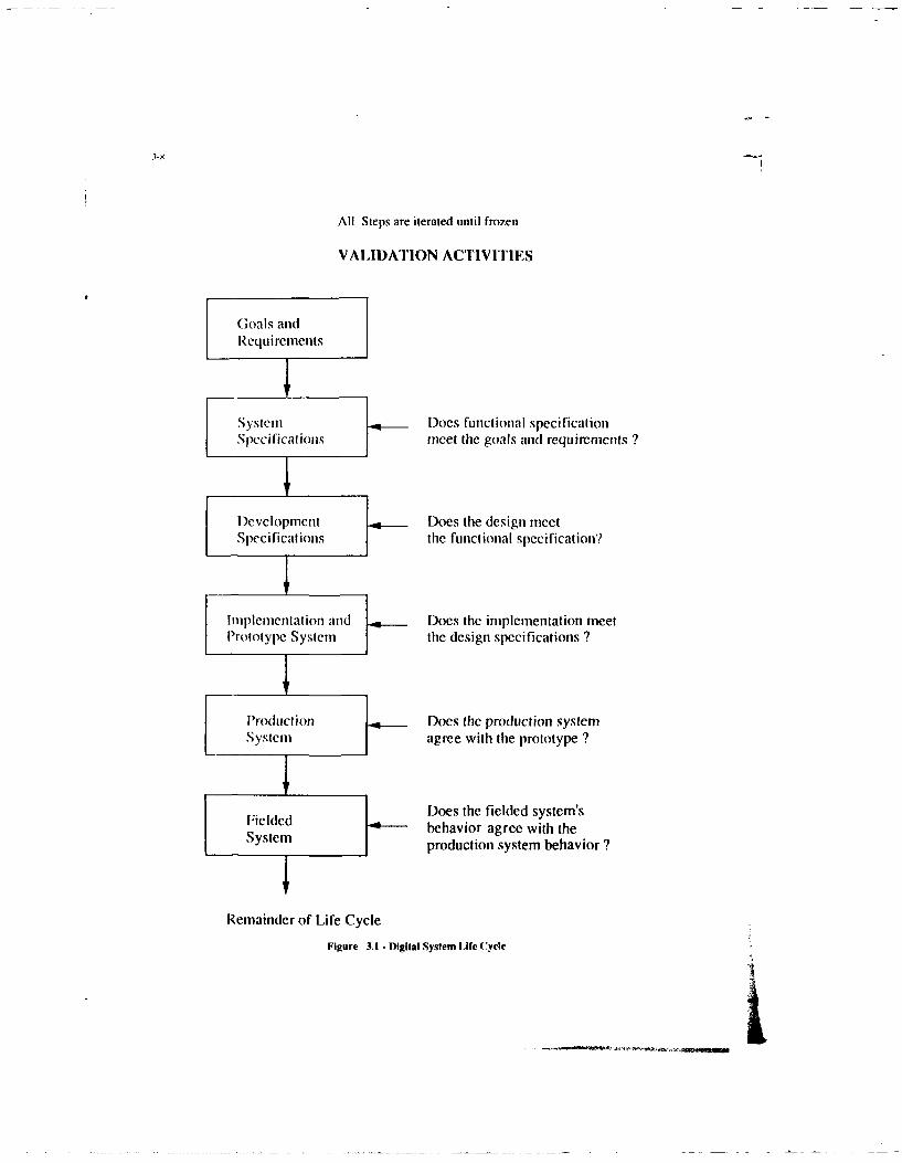
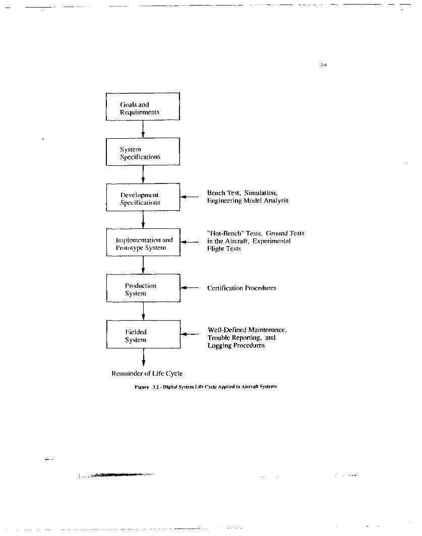
Chapter 3 - SOA Generic Development and Validation Process 3-13.0 Introduction 3-13.1 Relationship of FCCS Development to the Military Aircraft Life Cycle 3-13.2 The Life Cycle of a FCCS 3-13.3 Goals and Requirements 3-23.4 System Specification 3-23.5 Development Specification 3-23.6 Implementation and Prototype 3-33.7 Prototype Aircraft 3-33.8 Production System 3-4Appendix 3-1 - A Life Cycle Model of a Military Aircraft 3-4References 3-6
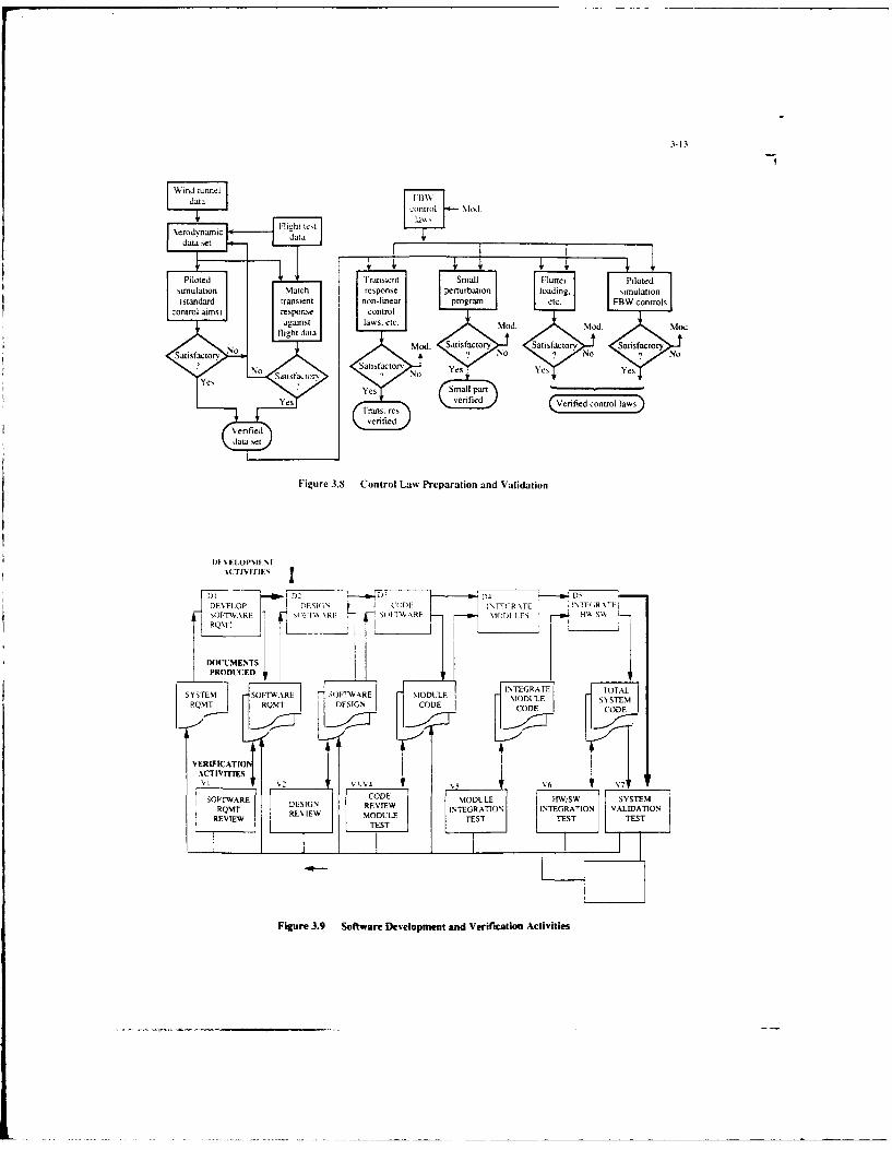
Chapter 4 - Current Methodologies and Techniques 4-14.1 Introduction 4-14.2 Development of the Customer Requirement Specification 4-14.3 Development of the Weapon System Specification 4-24.4 Development of the FCS Requirements Specification 4-24.5 Development of the FCS System Specification. Control Law Design Specification and 4-3
the System Quality Plan
Page
4.6 Development of the Requirements Specifications for Processing, Sensors and Actuation 4-44.7 Development of the Processing Sub-Systems 4-4
4.7.1 Development of the Hardware 4-44.7.2 Development of the Operational Flight Program 4-64.7.3 Development of the LRI Test Facility 4-9
4.8 Integrating the Hardware and Software 4-104.9 Integrating the LR I's to form a Sub-System 4-1I4.10 On Aircraft System Integration 4-124.11 Clearance of the FCS for First Flight 4-134.12 Flight Test 4-134.13 Production System Validation 4-154.14 Validation of the Fielded System 4-184.15 Special Topics 4-19
4.15.1 Traceability 4-194.15.2 Use of Formal/Semi Formal Languages 4-194.15.3 Project/National Specifications 4-194.15.4 Varying Criticality 4-194.15.5 Assessment of the Use of Test as the Principal Hardware Validation Method 4-204.15.6 Allowable Constructs in Software 4-204.15.7 Program Design Languages 4-214-15.8 Assessment of Software Validation Method 4-214.15.9 EMI Tests 4-22
References 4-22
Chapter 5 - Assessment of the State of the Art Validation Process 5-15.1 Introduction 5-15.2 Assessment Criteria 5-15 3 System Development Plan 5-35.4 Management of Validation Activities 5-45.5 Validation Elements 5-55.6 Validation of Piloted Simulation Systems for FCCS Validation 5-7
Chapter 6 - Trends in Flight Control System Design and Impact on Validation 6-16.1 Aircraft Projections 6-1
6.1.1 Introduction 6-16.1.2 Maneuverability 6-16.1.3 Survivability 6-26.1.4 All Weather/Night Operational Capability 6-26.1.5 Short Take-off and Landing Capability 6-26.1.6 Unmanned Vehicles 6-26.1.7 Hypersonic Vehicles 6-2
6.2 Systems Integration Trends and Validation Impacts 6-36.2.1 Introduction 6-36.2.2 Fire/Flight Control System Integration 6-36.2.3 Highly Integrated Flight/Propulsion Control Systems 6-4
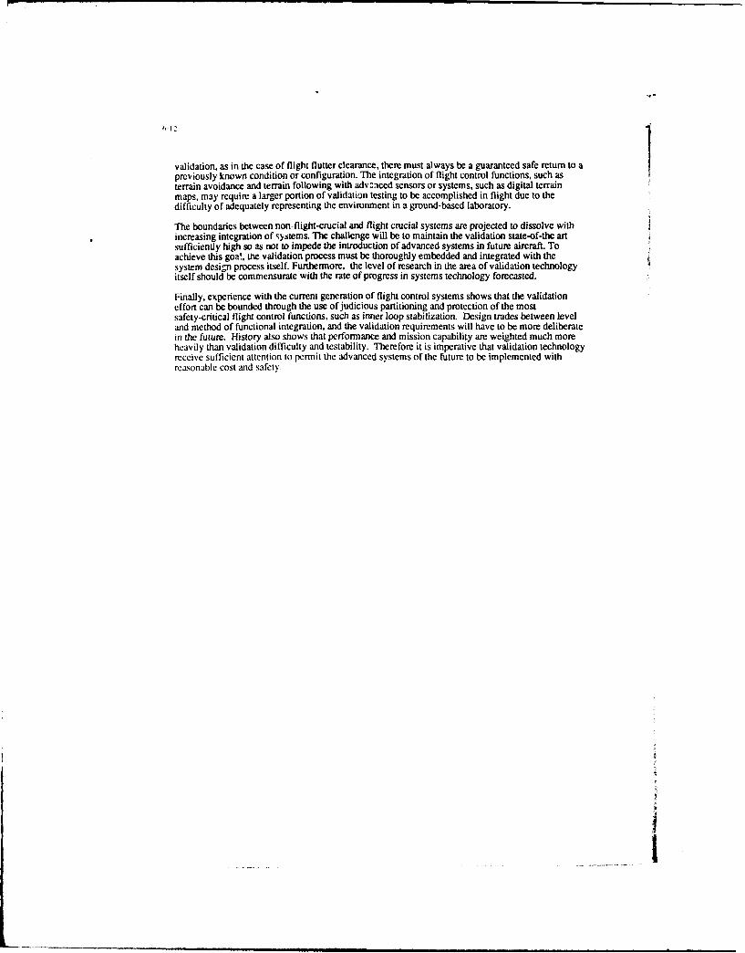
6.3 Emerging New Functional Capability 6-46.3.1 Introduction 6-46.3.2 Decision-Aiding Systems 6-46.3.3 Self Repairing, or Reconfigurable Flight Controls 6-56.3.4 Total Vehicle Energy/Thermal Management 6-56.3.5 High Bandwidth Flight Control System Function 6-56.3.6 Active Local Aerodynamic Control 6-6
7.4 Test and Evaluation 7-77.4.1 Automated Testing 7-77.4.2 Integrated Test Environments 7-87.4.3 Flight Testing 7-8
7.5 General Research in Validation Methods 7-87.5.1 Understanding the Validation Process 7-87.5.2 Specification and Design 7-97.5.3 Validation of Knowledge-Based Systems 7-97.5.4 Design and Evaluation 7-97.5.5 Data Base 7-9
Chapter 9 - Executive Summary 9-1Introduction 9-1State-of-the-Art in Flight Critical Control Systems 9-1SOA Generic Development and Validation Process 9-2A Life Cycle Model of a Military Aircraft 9-3Current Methodologies and Techniques 9-3Assessment of the SOA Validation Process 9-4Trends in Flight Critical Control System Design and Impact on Validation 9-6Emerging Test and Validation Technology 9-7Conclusions and Recommendations 9-8
vii
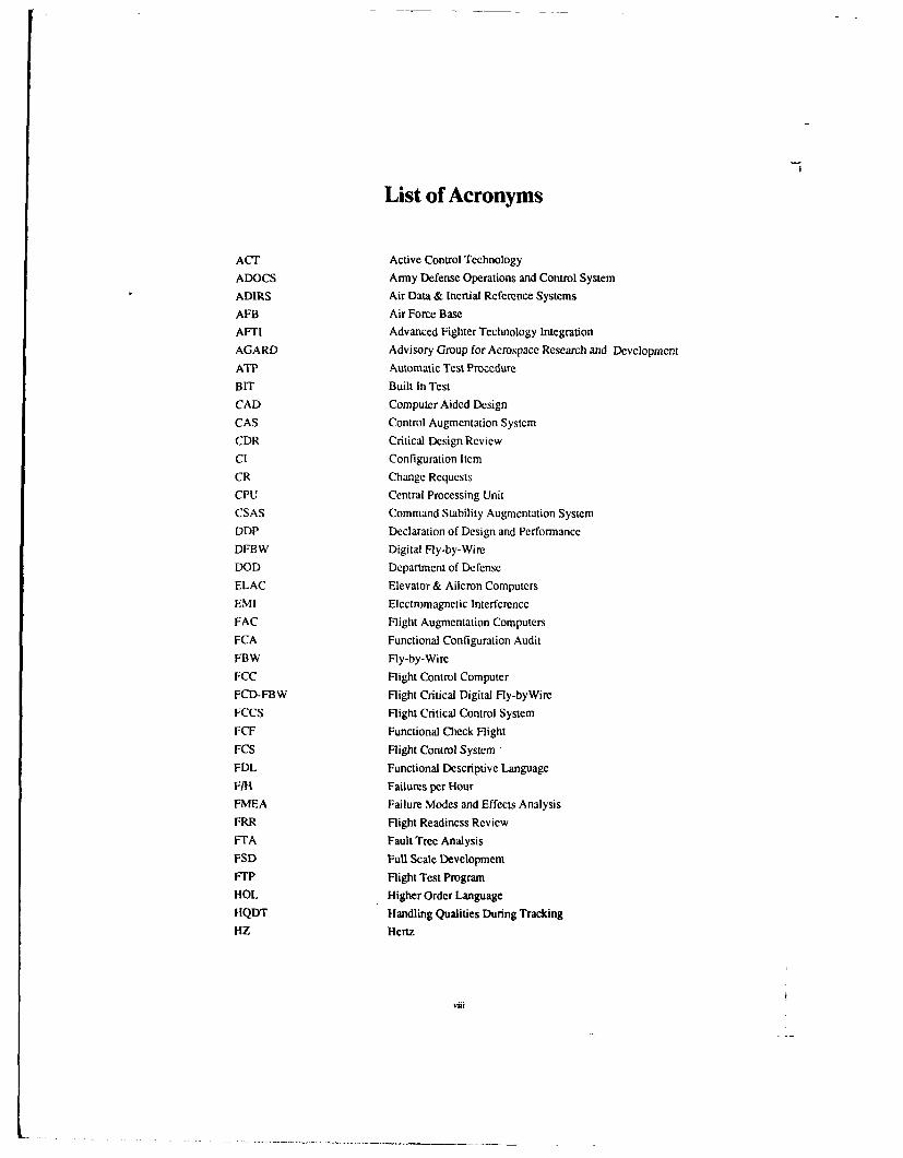
List of Acronyms
ACT Active Control Technology
ADOCS Army Defense Operations and Control System
ADIRS Air Data & Inertial Reference Systems
AFB Air Force Base
AFTI Advanced Fighter Technology Integration
AGARD Advisory Group for Aerospace Research and Development
ATP Automatic Test ProcedureBIT Built In Test
CAD Computer Aided Design
CAS Control Augmentation System
CDR Critical Design Review
Cl Configuration Item
CR Change Requests
CPU Central Processing Unit
CSAS Command Stability Augmentation System
DDP Declaration of Design and Performance
DFBW Digital Fly-by-Wire
DOD Department of Defense
ELAC Elevator & Aileron Computers
EMI Electromagnetic Interference
FAC Flight Augmentation Computers
FCA Functional Configuration Audit
FBW Fly-by-Wire
FCC Flight Control Computer
FCD-FBW Flight Critical Digital Fly-byWire
FCCS Flight Critical Control System
FCF Functional Check Flight
FCS Flight Control System "
FDL Functional Descriptive Language
F/H Failures per Hour
FMEA Failure Modes and Effects Analysis
FRR Flight Readiness Review
FTA Fault Tree Analysis
FSD Full Scale Development
FTP Flight Test Program
HOL Higher Order Language
HQDT Handling Qualities During Tracking
HZ Hertz
viii
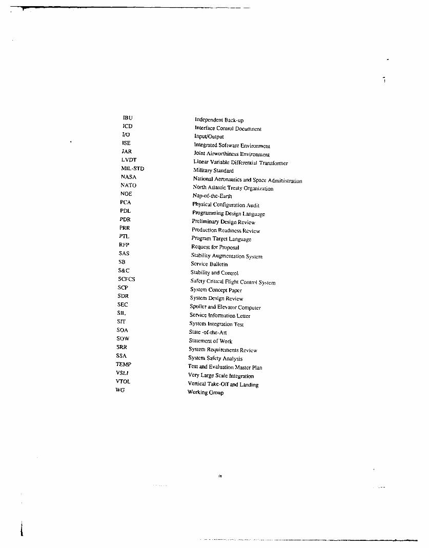
IBU Independent Back-upICD Interface Control DocumnentI/O Input/OutputISE Integrated Software EnvironmentJAR Joint Airworthiness EnvironmentLVDT Linear Variable Differential TransformerMIL-STD Military StandardNASA National Aeronautics and Space AdministrationNATO North Atlantic Treaty OrganizationNOE Nap-of-the-EarthPCA Physical Configuration AuditPDL Programming Design LanguagePDR Preliminary Design ReviewPRR Production Readiness ReviewPTL Program Target LanguageRFP Request for ProposalSAS Stability Augmentation SystemSB Service BulletinS&C Stability and ControlSCFCS Safety Critical Flight Control SystemSCP System Concept PaperSDR System Design ReviewSEC Spoiler and Elevator ComputerSIL Service Information LetterSIT System Integration TestSOA State -of-the-ArtSOW Statement of WorkSRR System Requirements ReviewSSA System Safety AnalysisTEMP Test and Evaluation Master PlanVSLI Very Large Scale IntegrationVTOL Vertical Take-Off and LandingWG Working Group
.. ...
CHAPTER 1
INTRODUCTION
1.1 Background
Automation and digital electronic control systems are being used in ever increasing levels in aircraft flightcontrol systems. The benefits of tliese advanced control systems have been dramatic, contributing to majorimprovements in aircraft performance and mission effectiveness. Full time digital fly-by-wire controlsystems with active controls of unstable aircraft modes have reached the point of being essential to theaircraft's safe operation. The safety-critical nature of these modem flight control systems requires anextremely high level of reliability and integrity, equivalent to that of the basic aircraft structure itself.
Although the first manned spacecraft and earliest experimental aircraft digital fly-by-wire control systemsused single thread elements" I, today's flight control systems employ extensive redundancy for any elementwhose failure could jeopardize vehicle safety. Triplex or quadruplex redundancy is often used for sensors,computers, actuators, and data communication links between them to provide continued operation in theevent of failures.
Control algorithms have grown in complexity as well, often involving several modes of control, withcomplex gain scheduling and interfaces with various other aircraft systems and subsystems. Control lawsare used to provide artificial longitudinal stability where the aircraft's stability margins have been relaxedor designed to be negative to gain maneuvering or cruise performance advantages. In some aircraft, theunaugmented divergence rate is so high, that total loss of the electronic flight controls would result invehicle dynamics which could compromise the crew's ability to egress.
The multiple redundant systems and the sophisticated control laws have resulted in a complex and time-consuming design, development and qualification process. Entire AGARD symposia and lecture series'have been devoted to the design and development aspects of advanced flight control systems 12
-5 1. The
qualification process, however, has also grown to be a major critical activity in the overall process ofachieving a safe and effective production flight control system, and has a technology aspect f its own.This has been recognized in a recent AGARD Working Group effort addressing the verific, .n andvalidation of real time software for flight control systems 16 1.
The qualification of the entire flight-critical flight control system, including both hardware and software,presents some difficult challenges. Hardware components can usually be tested quite readily forfunctionality and performance in a variety of environmental conditions, and in many cases, sufficientsupplier test data exists to provide credible failure rate data. However, it is not sufficient to combine all ofthese data in any credible manner to establish the reliability or failure tolerance of the overall flight controlsystem, given the usually complex interaction of all of the components and subsystems, and the action ofthe software in managing all of the elements in the system.
It is furthermore impractical, or impossible to test directly, the entire flight control system reliability orfailure tolerance, which is often expressed in terms of the "probability of loss of control per hour". The
design targets are often so small for this probabilitN t10 -5 to 10-9 per hour), that direct testing cannot beaccomplished in any credible manner, due to the length of time it would take to acquire statistical evidenceof the system's characteristics.
Although analyses do play a very importat part in the design, development, qualification, and certificationprocess, analytical techniques alone arc not sufficient to to assure that the extremely small control lossprobabilities have actually been achieved in a real design.
The practical qualification process must, then, be some combination of analysis, component testing,
subsystem testing, and integrated system testing, involving both the hardware and software in some logicalprocess, all designed to assure the company, the customer, and the independent certifying authorities, thatthe flight control system is both effective and safe. At the present time, there is no universally acceptedprocedure for qualifying and certifying a flight critical flight control system. Test processes, procedures,and philosophies differ among airframe manufacturers, suppliers, and customers. There is littleconformity in the certification requirements, except at a high level, and the companies and certifyingauthorities are both on a learning curve in this area.
The cost and impact of the qualification process is of such significance, that advances in the technology ofsystem qualification are expected to have a strong positive influence on vehicle safety, life cycle cost, andprogram schedules. Yet these processes have developed in more or less an ad hoc manner. It was thesefacts that led AGARD to establish a Working Group to closely examine the qualification process for flightcritical flight control systems with the objective of improving the process and providing some guidance forthe future.
1.2 Scope
The scope of this report, as it reflects the scope of Working Group 09 itself, is the assessment andprojection of the state of the art of the qualification process for flight critical flight control systems, withregard to flight safety. The establishment of aircraft performance or mission suitability is not included,except as it directly has a bearing on flight safety.
The focus of this report is on the validation process. Recognizing that verification can be considered to bea sub-process to validation, this report uses the term "validation" in its broadest sense, which includes thenecessary verification steps that take place within it.
Validation criteria for flight equipment and systems are based on the impact that the loss, or malfunction,of such equipment and systems have on flight safety. The determination of level of criticality is achievedby means such as design description, analyses, simulations, similarity and other appropriate methods. Thecriticality levels are most effectively negotiated between manufacturers and relevant regulatory agencies atthe earliest possible time, because they strongly affect the entire development process includingdevelopment and test methods; tools, techniques, and environments; documentation requirements; and useroperation and maintenance requirements.
The subject of this report is the validation process of flight systems which are critical to the control of theaircraft. Critical systems can include, for example, engine controls, large authority autopilots and weaponsystems, and full authority active flight control systems. This document, however, concentrates on thelatter and although addressing integration with other critical systems it assumes that there is a directapplication of the the principles involved.
1.3 Working Group Objectives
The objectives of the Working Group were established as follows:
1.3.1 Guidance on the Validation Process
To provide guidance to those concerned in the validation of flight critical control systems, namelysystem designers, aircraft designers and certification authorities.
To achieve this objective, the following aspects are addressed and reported:
(a) The phasing of the validation process and its relationshipto systems development.
(b) The structure for accomplishing the definition of therequirements, the testing for compliance and the formalacceptance that the requirements have been met.
1-3
(c) The techniques/methods appropriate for each phase of thevalidation process. This aspect will include guidance on thezoverage and depth of the techniques/methods.
(d) Systems design features which facilitate validation withinpractical constraints.
1.3.2 Future Validation Processes and Needs
To identify the ares of research which need to be explored to enable validation of the next generation of
flight critical control systems.
To achieve this objective, the following aspects are addressed and reported:
(f) The range aircraft systems and the technologies to beemployed in the next fifteen years which are likely tohave a major impact on validation methods.
(g) The new validation techniques which will have to bedeveloped to allow these systems/technologies to be usedsafely.
1.4 Organization of the Report
This report is partitioned to highlight the validation process, but it is not possible to separate validationfrom the design and development process itself. Therefore, the report first describes the state of the an inflight critical flight control systems in Chapter 2 to rrovide a common basis for understanding thevalidation requirements This is done by way of four examples which illustrate the range of designvariables in modem flight control systems. It is these types .,f systems which provide the structure for theassessment of the state of the art in validation.
In Chapter 3, a top level generic development and validation sequence is described, as well as a descriptionof the interrelationship of the vehicle development, systems development, and validation process. Thisserves as both a summary of the process and also as a guide to the detailed description of the processescontained in Chapter 4. In Chapter 5, a critical assessment is provided of the principal elements of thevalidation process. Chapter 6 contains the projection of trends in flight control design over the next 15years, along with the expected impact on the validation process. Chapter 7 contains the emerging tools andtechniques that will be needed to improve the validation process for the current generation of flight controlsystems as well as for those projected in Chapter 6. Chapter 8 contains conclusions and recommendationswhich are intended to provide guidance for future flight control design, development and validationtechnology developments.
REFERENCES
[1] Description and Flight Test Results of the NASA F-8 Digital Fly-by-Wire Control System,NASA TN D-7843, February, 1975
[2] Advances in Guidance and Control Systems Technology AGARD-CP-41 1,October, 1986.
[3] Fault Tolerant Design Considerations and Methods for Guidance andControl Systems, AGARD-AG-289, July, 1987.
[4] Computing Systems Configurations for Highly Integrated Guidance and Control Systems,AGARD-LS-158, 1988.
[61 The Implications of Using Integrated Software Support Environment for Design of Guidanceand Control Systems Software. AGARD Advisory Support N. 229 February 1990.
I -
2-1
CHAPTER 2
STATE OF THE ART IN FLIGHT CRITICALFLIGHT CONTROL SYSTEMS
2.1 Functional Requirements
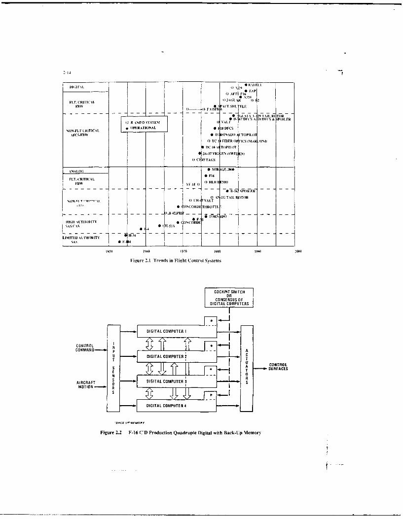
Functional requirements and the continuous evolution of FCCS automatic control system architecturesis shown in Figure 2. 1 11 . Limited authority, analog, stability augmentation systems were developedduring the 1950's; an example is the F- 104. These were followed by the development of flight critical,analog Fly-By-Wire (FBW) systems, which began during the early 1970's; examples are the F-16 andMirage 2000. The development of digital FBW (DFBW) systems started in the early '70's, and is stillevolving. Examples are: NASA F-8 DFBW, the Jaguar DFBW and the F-16C/D. The trend is clearlyestablished towards systems which are increasingly complex and which include more flight criticalfunctions.
Architectural complexity is increasing due to the increased functional criticality and the resulting needfor satisfying stringent reliability, availability and fault tolerance requirements. Moreover, the flightcritical control functions which DFBW systems are asked to provide, typically require frequent inputsto the control effecters, which cannot be effectively and consistently provided by the pilot, during some,or all flight regimes and conditions. Examples of this type of flight critical function include theintegrated engine and nozzle control of Vertical Take Off and Landing (VTOL) aircraft, and the func-tions commonly referred to as active controls technology (ACT) functions, which arc discussed in thenext paragraph. Additional increased complexity results from the requirement of integrating many ex-isting and new functions for improving performance, for extending the flight envelope, and fordecreasing pilot workload. Examples of functions which are being considered for integration includeflight control, propulsion control, weapons control, guidance, navigation, flight management, thermalmanagement, etc.
The design of many high performance aircraft rely on augmentation systems for providing some of thesafety margins traditionally provided by inherent aerodynamic stability and the structural strength andstiffness of the basic airframe. During the design cycle of the aircraft, the availability of ACT is takeninto account to relax the constraints in the aerodynamics, structures and propulsion systems, whileachieving the same effective margins with the active system. Typical applications of ACT include:load alleviation and structural mode control, relaxed stability margins, aerodynamic configurationmanagement, maneuver enhancing or limiting and other complex functions. Examples of aircraft whichuse ACT systems are: a) the Boeing B-52 (G and H) gust loads alleviation for increasing the wingstructural fatigue life; b) the F-16, and the X-29 stability augmentation systems for providing stabilityand enhancing maneuvering and cruise performance; c) the Lockheed L-101 1-500 maneuver loadcontrol to extend wing span without structural changes of the wing; and d) the AIRBUS A-320 enve-lope limiting system providing protection from intrusions into unsafe regions of the flight envelope.Clearly the stability augmentation system of an aircraft which is as inherently unstable as the X-29 is acritical function. In some cases, other ACT functions may also be flight critical.
The boundaries of flight critical control functions have also grown beyond classical control systems,especially in the case of military applications. Flight control functions and avionics sensory functionsare integrated in common architectures to satisfy the mission requirements of advanced military aircraft.Examples are heliccter nap-of-the-earth (NOE) and high speed terrain-following/terrain avoidancemissions. These missions require that sensory functions such as obstacle detection, terrain data, radaraltitude, target acquisition and tracking, and inertial reference system data, be carefully integrated withflight path control functions. These types of systems are evolving to flight critical as a result ofincreasingly stringent mission requirements.
2.2 State of the Art Digital Flight Control SystemConfigurations
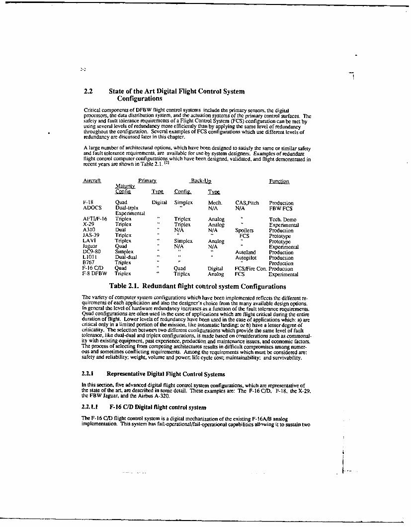
Critical components of DFBW flight control systems include the primary sensors, the digitalprocessors, the data distribution system, and the actuation systems of the primary control surfaces. Thesafety and fault tolerance requirements of a Flight Control System (FCS) configuration can be met byusing several levels of redundancy more efficiently than by applying the same level of redundancythroughout the configuration. Several examples of FCS configurations which use different levels ofredundancy are discussed later in this chapter.
A large number of architectural options, which have been designed to satisfy the same or similar safetyand fault tolerance requirements, are available for use by system designers. Examples of redundantflight control computer configurations which have been designed, validated, and flight demonstrated inrecent years are shown in Table 2.1. 121
ExperimentalAFTI/F-16 Triplex Triplex Analog Tech. DemoX-29 Triplex Triplex Analog ExperimentalA310 Dual N/A N/A Spoilers ProductionJAS-39 Triplex " FCS PrototypeLAVI Triplex Simplex Analog PrototypeJaguar Quad N/A N/A ExperimentalDC9-80 Simplex Autoland ProductionLIM I Dual-dual Autopilot ProductionB767 Triplex .. ... ProductionF-16 C/D Quad Quad Digital FCS/Fire Con. ProductionF-8 DFBW Triplex Triplex Analog FCS Experimental
Table 2.1. Redundant flight control system ConfigurationsThe variety of computer system configurations which have been implemented reflects the different re-quirements of each application and also the designer's choice from the many available design options.In general the level of hardware redundancy increases as a function of the fault tolerance requirements.Quad configurations are often used in the case of applications which are flight critical during the entireduration of flight. Lower levels of redundancy have been used in the case of applications which: a) arecritical only in a limited portion of the mission, like automatic landing; or b) have a lesser degree ofcriticality. The selection between two different configurations which provide the same level of faulttolerance, like dual-dual and triplex configurations, is made based on considerations such as commonal-ity with existing equipment, past experience, production and maintenance issues, and economic factors.The process of selecting from competing architectures results in difficult compromises among numer-ous and sometimes conflicting requirements. Among the requirements which must be considered are:safety and reliability; weight, volume and power, life cycle cost; maintainability; and survivability.
2.2.1 Representative Digital Flight Control Systems
In this section, five advanced digital flight control system configurations, which are representative ofthe state of the art, are described in some detail. These examples are: The F-16 C/D, F-18, the X-29,the FBW Jaguar, and the Airbus A-320.
2.2.1.1 F-16 C/D Digital flight control system
The F-16 C/D flight control system is a digital mechanization of the existing F-16A/B analogimplementation. This system has fail-operational/fail-operational capabilities allnwing it to sustain two
2-3
similar failures and still provide full performance. This is achieved by a quad architecture of criticalsensors and digital processors, and a redundant actuation system.
The flight control system includes four Mil Std 1750A processors and an Independent Back-Up (IBU)system, also quad, which uses the primary system processors and independently developed software.The IBU provides protection against possible generic software errors. Reversion to the IBU is made asa result of either automatically detected failures or pilot selection.
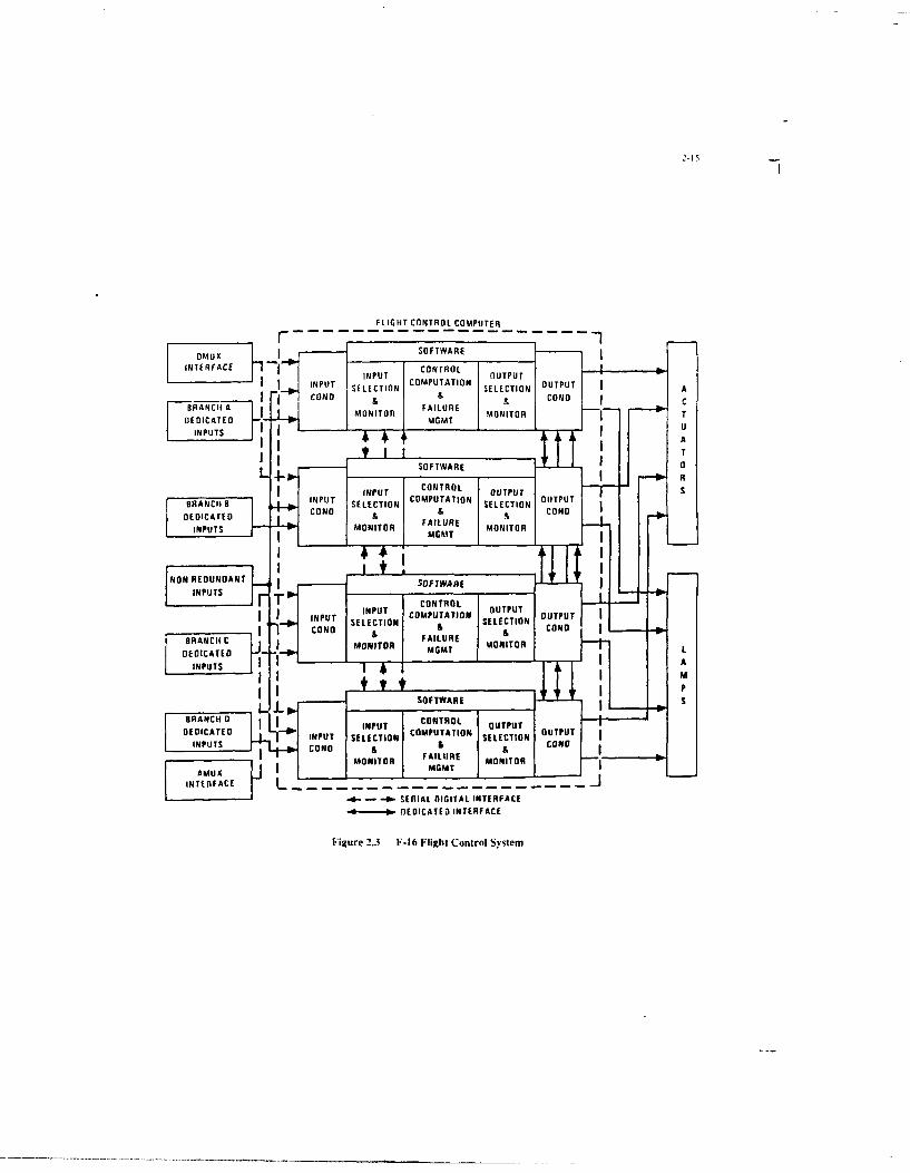
The configuration is asynchronous. Each primary channel uses 24K words (16 bits/word). Thesoftware is coded in Jovial J73, using floating point arithmetic. Each back-up channel uses 4K wordsand is coded in Assembly language. Reversion to the back-up software is made by switching theComputer Processing Unit (CPU) to the memory banks of the back-up system. The primary flightsoftware has a multi-rate execution structure. The basic rate is 64 Hz, which corresponds to a frametime of 15.6 msec. Comparison monitors among the four primary channels are the primary failuredetection mechanisms. The thresholds for the trip levels are set as a function of the rate of change ofthe variable. A schematic of the digital flight control system is shown in Figures 2.2 and 2.3.
The flight critical sensors (rate gyros and normal acceleration), and the pilot stick sensors are also quadredundant. The sensor inputs are voted in software. Output commands to the servo-actuators are voted.Fail-operational/Fail-operational capabilities are also provided for the servo actuators. The provenelectro-hydraulic servo-actuators of the analog F-16 have been retained in the F-16 C/D.
2.2.1.2 F-18 Digital flight control system
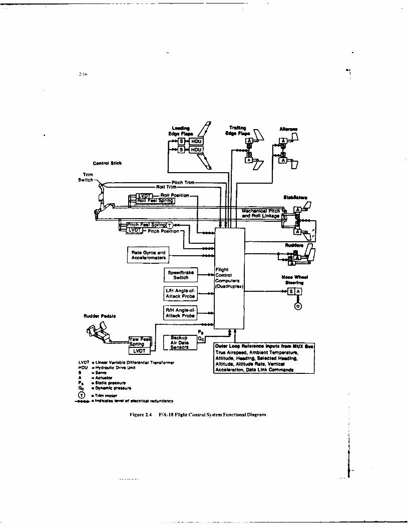
The F-18 FCS is a digitally mechanized quadruplex fly-by-wire system providing stability, control andautopilot functions, and interfaces with many of the highly integrated avionic systems through a Mil Stdmultiplex data bus. A functional diagram of the flight control system is shown in Fig. 2.413 .
The primary control law computations are performed by four digital computers operating in parallel.Redundancy provides fail-op/fail-op capabilities. A mechanical back-up system is provided to thestabilator surfaces for pitch and roll control. An unaugmented, analog back-up system is provided forroll and yaw control, through aileron and rudder surfaces. The flight control system used four GeneralElectric 701 microprogrammed, general purpose, 16 bit processors. The operational programs werewritten in Jovial 73 using fixed point arithmetic. The Vax hosted software development environmentwhich was used is the same as that used for the F-16C/D. The design was documented using a pro-gramming design language (PDL). The software is highly modular and static module testing wasperformed prior to integration and real time testing. The operational programs were identical in all fourchannels, which were frame synchronized by an executive, which also scheduled all tasks atcomputation iteration rates of 80,40, 20, and 10 per second.
It is interesting to note that: a) the control laws require about 22% of the memory; b) preflight anu in-flight Built-In-Test (BIT), the largest function, requires 42% of the memory; and c) Input/Output (I/O)processing and redundancy management requires 18% of the memory. This data distribution is rathertypical and will be discussed further in following paragraphs.
The sensors have a level of redundancy proportional to the criticality. Rate gyros and accelerometersare dual. The electrical redundancy is quad. Control stick and rudder pedal displacement sensors aresimplex, but they too have quad electrical redundancy. Other non critical sensors have a lower level ofredundancy.
The redundancy of the actuation systems set by the criticality of each control function 1'4 (Ref. 3). The
most critical controls, for which aerodynamic redundancy is not available, are the stabilators and thetrailing edge flaps. The redundancy of the stabilator actuator is quad electrical and dual hydraulic. Asimplex mechanical back-up control system is also provided, in the case of multiple electrical failures.The hardware redundancy requirements decrease in the case of control functions which have inherentaerodynamic redundancy, like the ailerons.
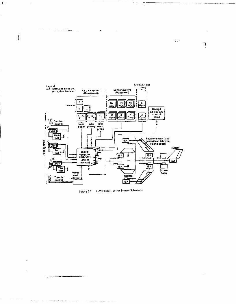
2.2.1.3 X-29 flight control system
The Grumman Aerospace X-29 advanced technology demonstrator aircraft has an inherent 35%negative static stability margin. As a result, the flight control system which is required to produce
2-4
acceptable handling qualities, is flight critical throughout the flight envelope. The flight control systemwas developed and built by a Grumman/Honeywell team and implemented with HDP-5301 processors.The research objectives of the X-29 program are focused on basic aerodynamic and control technology,rather than fault tolerant flight control system architectures. As a result the X-29 FCS configurationincludes some ad-hoc solutions which are not well suited for a production system. The X-29 FCS does,however, provide the very high level of reliability and fault tolerance that such a flight critical systemrequires. It includes a primary triple redundant digital flight control system that used a majority votetechnique to detect and isolate a faulty channel. Each flight control system channel has two digitalprocessors; one control law processor, which uses floating point arithmetic; and one I/O processorwhich uses integer arithmetic. This configuration was selected to satisfy the tight execution timeconstraints, which could not be met by a single processor configuration. Both processors are coded inassembly language for optimizing execution speed. If an entire sensor set fails, a reversion mode can beselected which only uses a minimum number of sensors. If two or more of the digital channels shouldfail, the pilot can select a triple redundant analog system. In summary, the primary flight control sys-tem has two triplex reversion systems. One of these is digital, which is selectable in the case of somesensor set failures, and the other is analog. A schematic of the flight control system configuration isshown in Fig. 2.5.
The basic triplex configuration of the flight processors was also adopted for the critical sensors andactuators. Critical sensors include rate gyros and accelerometers (three axes), and the pilot control stickdisplacements.
Software specifications were first developed by Grumman and by Honeywell. Honeywellspecifications included the redundancy management and mode selection, in addition to the control lawsspecified by Grumman. Honeywell specifications were written first in English and then in structuredPDL. Software is highly modular. Module testing was performed prior to module integration andsoftware/hardware integration.
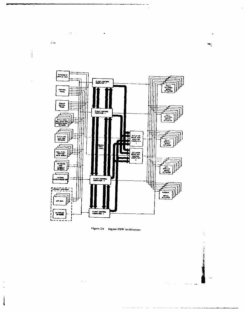
2.2.1.4 Jaguar FCS
The Jaguar Integrated Flight Control System is a full authority, quadruplex DFBW system. The overallsystem architecture is shown in Fig. 2.6 151.
The critical sensors are the pilot control stick displacements, rate gyros, and pitch and yaw trim. Theseare all quad. Other non-critical sensors are either triplex, duplex or simplex.
The primary control surfaces arc: left and right tail plane, rudder, and left and right spoilers. Theconfiguration of the actuation system of the primary control surfaces is dual-triplex. For each controlsurface, six independent electrical drive signals are used to drive six control valves which, in groups ofthree, drive a dual tandem power stage. The hydraulic supply is dual.
The surface position commands and sensor inputs are processed in the four identical digital flight con-trol computers. The flight control computer was designed around a bit slice processor developed byGEC Avionics, to ease the integrity assessment task. The basic processor configuration is quadruplex
to satisfy the requirements of a system probability of loss less than 10-7 and to survive any twoelectrical failures. Triplex configurations were not used because of their reliance on self monitoringtechniques. The four processors are loosely synchronized so that the major computational frames areinitiated at the same time, and the signal values used by the signal selectors and therefore by the controllaw algorithms, are taken from the same time samples of the input signals. Sensor data is cross fed toall processors and then voted so that interlane tolerances are reduced to improve failure monitoring.
Two additional identical analog processors have been added to match the dual triplex configuration ofthe actuation system. Each analog processor receives position commands from the four digitalprocessors, consolidates those inputs and generates the position commands for two of the six first stagecontrol valves of the actuation system. A major objective of the program was to establish whether sucharchitectures could be proven. The software is common to all four processors, which presents theproblem of a generic error leading to a safety critical situation. Very tight control measures were thenexercised to guard against that possibility.
The software design was based on functional specifications developed by the airframer (BAe). Thenext stage of functional decomposition was the development of a Software Requirements Document,which detailed how the software would provide the required functions, the structure of the software, the
a ..
interfaces, the major algorithms, etc. The major functions provided by the software are: Executive;Data Handing; Signal Selection and Monitoring; Control Laws; Failure Identification andMonitoring; Built-In-Test.
The software is coded in Assembly language. An enhanced version of an existing instruction set(BOEING YC-14) was used. The enhancements improved the throughput of the flight controlalgorithms. The software support tools were derivatives of tools of proven maturity. The softwaredevelopment process was very structured. The Software Requirement Document was the key documentwhich controlled the design implementation. Strict standards were imposed throughout to emphasizesimplicity and clarity.
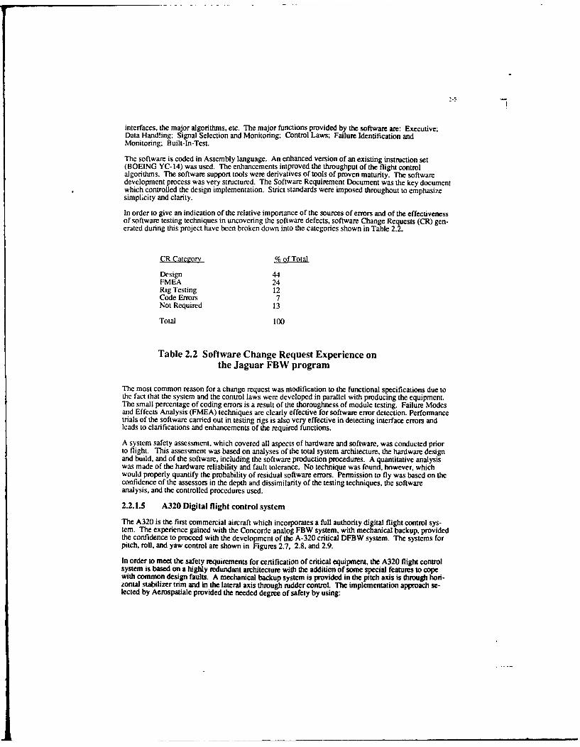
In order to give an indication of the relative importance of the sources of errors and of the effectivenessof software testing techniques in uncovering the software defects, software Change Requests (CR) gen-erated during this project have been broken down into the categories shown in Table 2.2.
Table 2.2 Software Change Request Experience onthe Jaguar FBW program
The most common reason for a change request was modification to the functional specifications due tothe fact that the system and the control laws were developed in parallel with producing the equipment.The small percentage of coding errors is a result of the thoroughness of module testing. Failure Modesand Effects Analysis (FMEA) techniques are clearly effective for software error detection. Performancetrials of the software carried out in testing rigs is also very effective in detecting interface errors andleads to clarifications and enhancements of the required functions.
A system safety assessment, which covered all aspects of hardware and software, was conducted priorto flight. This assessment was based on analyses of the total system architecture, the hardware designand build, and of the software, including the software production procedures. A quantitative analysiswas made of the hardware reliability and fault tolerance. No technique was found, however, whichwould properly quantify the probability of residual software errors. Permission to fly was based on theconfidence of the assessors in the depth and dissimilarity of the testing techniques, the softwareanalysis, and the controlled procedures used.
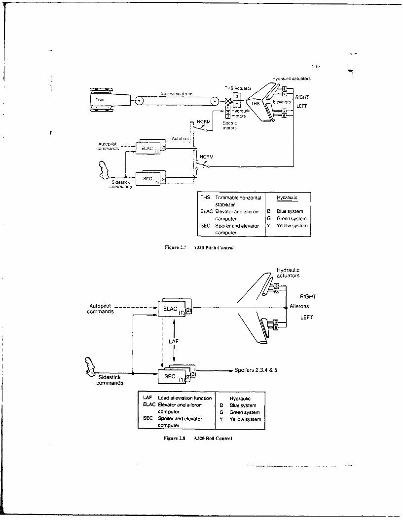
2.2.1.5 A320 Digital flight control system
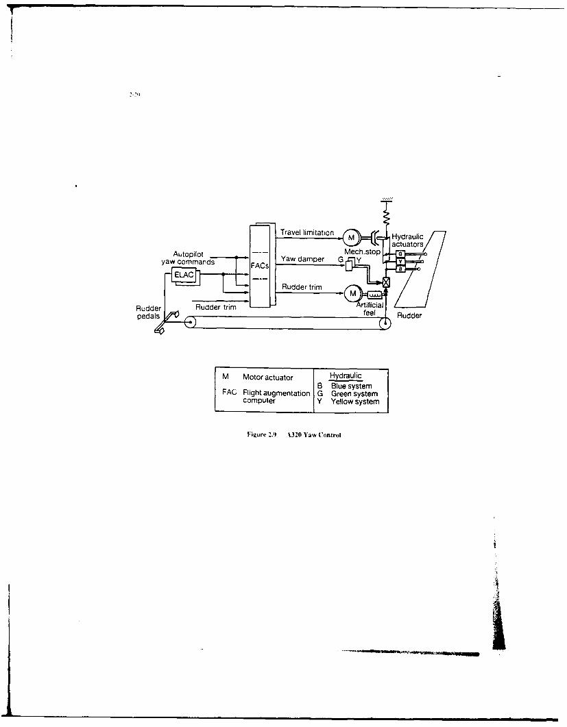
The A320 is the first commercial aircraft which incorporates a full authority digital flight control sys-tem. The experience gained with the Concorde analog FBW system, with mechanical backup, providedthe confidence to proceed with the development of the A-320 critical DFBW system. The systems forpitch, roll, and yaw control are shown in Figures 2.7, 2.8, and 2.9.
In order to meet the safety requirements for certification of critical equipment, the A320 flight controlsystem is based on a highly redundant architecture with the addition of some special features to copewith common design faults. A mechanical backup system is provided in the pitch axis is through hori-zontal stabilizer trim and in the lateral axis through rudder control. The implementation approach se-lected by Aerospatiale provided the needed degree of safety by using:
'-h
-3 identical Spoiler & Elevator Computers (SEC) made by Aerospatiale-2 identical Elevator & Aileron Computers (ELAC) made by Thomson-CSF-3 identical Air Data & Inertial References Systems (ADIRS) with separate
sensors made by Honeywell-2 identical Flight Augmentation Computers (FAC) made by SFENA-3 separate hydraulic channels (I common + I for each side of airframe)-2 separate main electrical power supplies plus 3 backups (Auxiliary Power Unit,
Ram Air Turbine, batteries)
The loss of control of the aircraft is highly improbable, either in the pitch axis (in that both SECs andELACs control the elevator) or in the lateral axis (in that SECs can control the spoilers and ELACs theailerons) due to the following:
-The hardware of SECs and ELACs are dissimilar: i. e. dissimilar specs, dissimilarcomponents up to processors (80186 for SECs, 68000 for ELACs), different suppliers
-The software is dissimilar: i. e. dissimilar specs, different suppliers, dissimilar methodolo-gies, tools, and languages.
Furthermore, each FCC (SEC or ELAC) consists of two separate channels that communicate by anARINC 429 bus (asynchronous point-to-point serial data link, mainly used in commercial transport air-craft). The control channel computes the control laws and actuates the surfaces (ailerons, spoilers andelevators) whereas the monitor channel computes control laws and checks the correct actuators, andmonitors the control channel. Although they are installed in the same box, the control and monitorchannels use fully independent hardware (even for power supply modules) and dissimilar software (e.g:for SEC. the control channel is written in assembly language by one engineering team; the monitorchannel is written in Pascal by another team; fixed point arithmetic is used; thorough testing to the DO178A level I software requirements). The channels are loosely synchronized.
Output data from the ADIRS are voted by SECs or ELACs before being used. Each ADIRS includesbuilt-in-test (BIT) which provides additional robustness to the voting scheme of the Flight ControlComputers with respect to self detected faults (the self detected faulty ADIRS is excluded from thevoting process). Threshold values are a function of several factorsp of computational algorithms.
Side stick controllers are used which are not mechanically coupled. Each FCC includes a priority logicbased on both sides stick signals. Normally one of the FCC's is the master, while the others are eitherin standby or in a slave mode. The masters choice varies depending on the surface. In case of failure,reversion inside each computer (alternate control laws) or to an alternate computer is fully automatic.
2.3 Implication of Design Choices on the Validation Process
In this section, the implications of various architectural characteristics on the verification andvalidation process are discussed.
2.3.1 Architectural Issues
The basic configuration of three of the five flight control systems which have been described is a qua-dniplex configuration. The X-29 flight control system has a triplex primary configuration which canrevert to a triplex analog back-up system.
Considering typical reliability assumptions for single channel failures, quad redundant configurations
can be shown to meet the flight failure rate of 10- 7 Failures/Hour(F/H). These configurations detectand isolate faults, in real time, based on majority voting algorithms. If a failure occurs when only twochannels are operational, then reversion to a degraded control mode, or to a fail safe configuration doesoccur.
Right critical system fault tolerance and reliability requirements can also be met by triplex configura-
'-7
tions, if self test techniques with an appropriate failure coverage are utilized. If the assumption is madethat the failure rate of a simplex flight control system channel is of the order of 10"3 F/H, then a triplexsystem can satisfy the 10"7 F/H requirement only if an overall failure coverage equal to , or greaterthan, 96.7% can be achieved with a combination of self test techniques. That coverage, however, isdifficult and costly to accomplish, demonstrate and validate. As a result, even if self test techniques canreduce the required hardware redundancy, they are seldom used for that purpose in flight criticalapplications. Self test techniques, however, are often implemented for the following purposes: a)detecting failures in flight control system components which are only active in limited regions of theflight regimes, like autoland, and b) supporting the off line maintenance process.
Other major configuration issues which effect the validation process of flight critical systems are: a)synchronous vs. asynchronous; b) use of back-up systems; and c) separation of critical and non criticalfunctions. They are briefly discussed in the following paragraphs.
2.3.1.1 Synchronization Techniques
There are three broad categories of synchronization techniques. The boundaries between them are notsharp, and a variety of perturbations of these basic techniques have been used in operational andexperimental DFBW systems. All three synchronization schemes have been developed to flightworthymaturity.
Tight Synchronization
The tightest form of synchronization is instruction-level synchronization, where a common clock isused to drive each of the CPU's in step, thus causing all of the CPU's to execute exactly the sameinstruction at the same time. A voting plane at the sensor input is provided to ensure that each channelsecures an identical set of input data. This results in an automatic bit-identical output from each of thecomputers. This permits straightforward cross-channel checking at the output, at the least significant bitlevel. The validation of the failure detection and isolation system is simplified because bit-by-bitchecking is a relatively simple process and because of the knowledge that all computers are preciselysynchronized in time.
Tight synchronization does require a common, fault-tolerant clock to provide timing signals to allcomputers. This mechanism becomes a source of potential common-mode faults or errors. Such asystem was used to synchronize the triplex digital flight control system in an experimental U.S. Armyhelicopter program, called TAGS (Total Automatic Guidance System).
Frame Synchronization
A looser form of synchronization is "frame" synchronization, the frame being the shortestcomputational segment in the application program. This is also often termed the "major cycle". In thisapproach, all processors rendezvous at the end of a computational frame and resume processing after anexchange of information. Typical synchronization skew varies from 20-50 microseconds, depending onthe approach used. In this approach, hardware synchronization of the clocks is not required, and thecomputers are not executing the same instructions at the same time. Voting planes at the sensor inputcan produce bit-identical outputs, although skewed by the synchronization variation. Becausesynchronization skew is small, analog voting, and cross-channel comparison at the analog level can beused for fault detection and isolation. The design of output failure detection and isolation requires thesmall synchronization skew to be accommodated in threshold selection. Validation of this approach ismore complex than for zight synchronization. The synchronization algorithm is a source ofcommon-mode faults or errors, and resynchronization following an "upset" is often a challenge.
This form of synchronization is common in contemporary DFBW systems, and is characterized by amoderate amount of design and validation effort required for effective implementation. The F-18production DFBW system and the experimental F-8 DFBW, Jaguar DFBW system, and X-29 DFBWsystems used this form of synchronization.
________________
Asynchronous Systems
In this approach, each channel executes its program independently of the other channels. The computersstill exchange information, but all exchanges are designed to be possible for any synchronization skew.One motivation for this approach is to minimize the potential for common-mode faults or errors, usingthe fact of interchannel skew as a means of avoiding correlated faults in the channels. Input data skewcan be reduced by operating the input process at a rate higher than the computational cycle.
The design of the output voting scheme must include considerations of maximum time skew andvarying time skew, because output command variations among channels vary with synchronizationskew. The validation process must account for the fact that the channels can be in an infinite number ofrelative states. The asynchronous approach is used in the F-16 C/D production DFBW system.
2.3.1.2 Availability of Dissimilar Back-Up Systems and Reversion Configurations
Alternate control methods have generally been provided to "back up" primary digital fly-by-wire sys-tems, in the event of loss of the entire primary system. These systems provide control over a subset ofthe aircraft's flight envelope, and usually offer degraded aircraft operational capability. Both hardwareand software dissimilarity is often used in flight critical applications. The major reason for using dis-similarity is preventing catastrophic consequences in the case of a) common errors in all channels,including design errors; or b) exhaustion of spares in the primary control channels. As the level ofconfidence increases relative to the operational reliability of digital channels, the primary concern isundetected common errors in all channels.
All processor channels of the Jaguar Fly-by-Wire flight control system, as an example, use identicalhardware and software, and reversion is not provided to a degraded control mode, in the case of designerrors or exhaustion of spares. The advantage of using identical software and hardware is that only oneset of hardware components, one set of software programs, and a single software developmentenvironment are needed. The disadvantages, relative to the validation process, is that it requires ex-haustive and labor intensive effort for achieving the confidence that the system is absolutely free of anydesign error. The approach was clearly successful in the case of the Jaguar DFBW flight control sys-tem, a technology demonstrator program. Clearly there is a "trade off" to be made between the in-creased resource required to validate a system with a similar architecture and the lower recurring cost ofthe implementation.
The prevalent approach is to use some form of dissimilarity in flight critical applications. In fact, theother four example systems previously discussed all use some form of dissimilarity in the processingelements of the flight control system. The F-16 has a primary flight control system and a back-upsystem which uses the same hardware as the primary system, and dissimilar software. Certain pilot aidsare deleted, but full envelope performance is maintained. The F-18 has a mechanical back-up systemfor pitch and roll control, and an analog back-up system for all control axes. Finally, the A-320 exten-sively utilizes dissimilarity in both hardware and software to achieve the high degree of reliability re-quired for certification. The disadvantages of dissimilarity, in the primary or back-up systems, is that itrequires additional hardware and software. The advantages are that it diminishes the concerns thatresidual, undetected design errors could have catastrophic consequences.
In all cases with an alternate control capability, that system must undergo a validation process similarto that for the primary system. In addition, the interfaces between the systems must be shown not to in-troduce catastrophic failure mechanisms.
2.3.1.3 Partitioning of Functions with Different Criticality
The development and verification costs of flight control system escalate very rapidly as a function ofthe criticality level. Therefore it is important to partition functions which have different levels ofcriticality. Function "A" is partitioned from function "B" if no action from function "B" can cause afailure in function "A." If partitioning can not be demonstrated and, function "B" is less critical than"A," then "B" automatically assume the same high level of criticality as function "A," because a failureof "B" can cause a failure in "A." Partitioning can be achieved with a combination of software and/orhardware techniques.
2.3.2 Software Issues
The structure of the embedded flight software reflects the critical and complex nature of the application.The structure, by design, is very simple. It involves the repetitive execution of sequences of
application tasks, at fixed execution rates which are multiple of a basic frequency. Common values ofthe basic frequency are 200, 100, 80, and 60 Hz. The application tasks are not interruptible. Onceinitiated they must execute to completion, within the allocated time. The main advantage of thisstructure is that it significantly reduces the number of system states which must be verified, byeliminating the uncertainties related to random interruptions of the execution of critical tasks.
If additional processing time is available, low priority, interruptible tasks are executed. This commonlyused foreground/background structure makes optimum use of the available resources and, at the sametime, it minimizes the complexity of flight critical software.
The software needed to perform the most critical control functions is typically replicated in all channels.Less critical functions might be performed within some of the channels only. To gain a betterunderstanding of the computational requirements of such systems, the software is partitioned accordingto the major functions which must be performed. They are:
a) Application. The algorithms included in this function are those required for sensorprocessing and filtering, control and navigation algorithms, computation of control command, etc.
b) Logic. Modules in this category perform the computation required for switching controland flight mode, and engaging/disengaging logic. They use almost exclusively Boolean statements.
c) Testing and Voting. These modules perform real time tests on processors, memory,sensors and actuators. They manage and control the overall system configuration, as a function ofdctected failures. BIT is included in this category.
d) i/O. The modules perform data handling and formatting, data transmission and display.Peripherals drivers and included in this category.
c) Executives. The modules perform the task of initializing power-up procedures,synchronization, scheduling and timing.
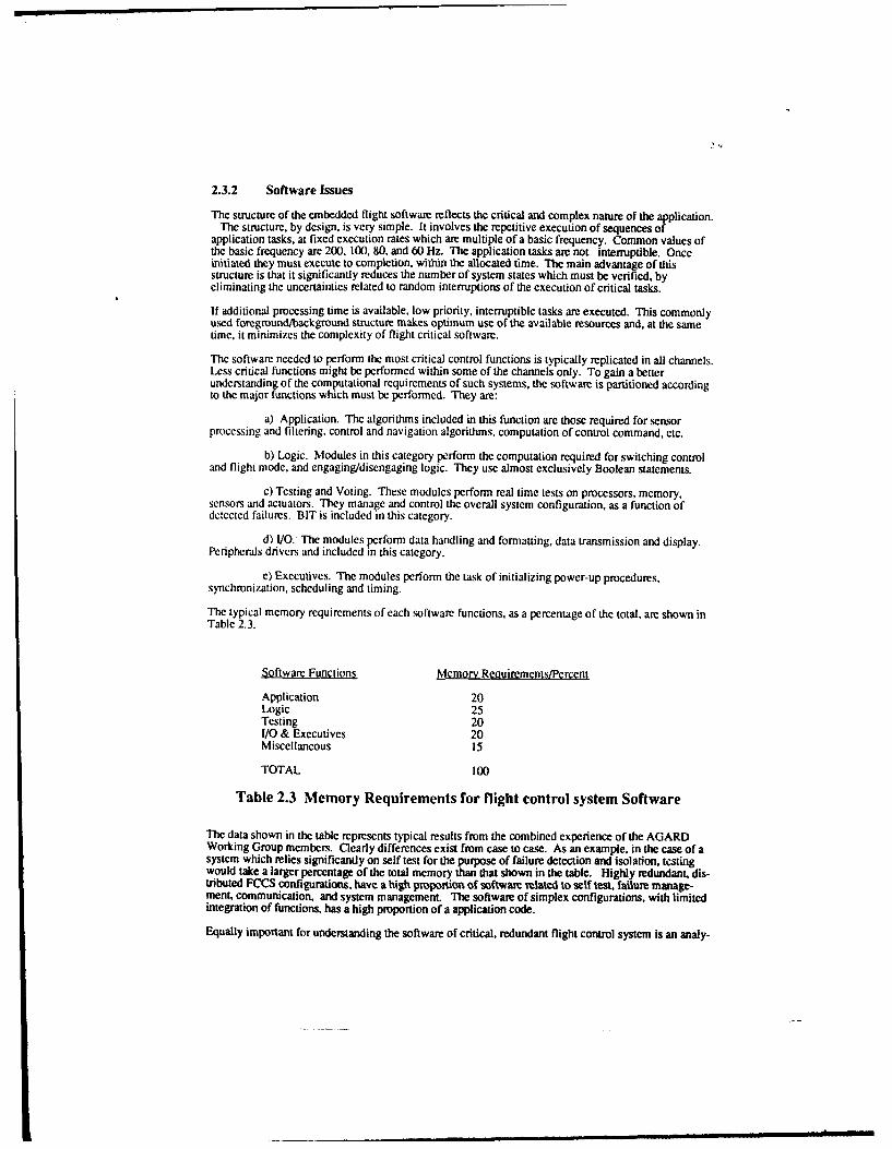
The typical memory requirements of each software functions, as a percentage of the total, are shown inTable 2.3.
Table 2.3 Memory Requirements for flight control system Software
The data shown in the table represents typical results from the combined experience of the AGARDWorking Group members. Clearly differences exist from case to case. As an example, in the case of asystem which relies significantly on self test for the purpose of failure detection and isolation, testingwould take a larger percentage of the total memory than that shown in the table. Highly redundant, dis-tributed FCCS configurations, have a high prporim of software related to self test, failure manage-ment, communication, and system management The software of simplex configurations, with limitedintegration of functions, has a high proportion of a application code.
Equally important for understanding the software of critical, redundant flight control system is an analy-
-1W
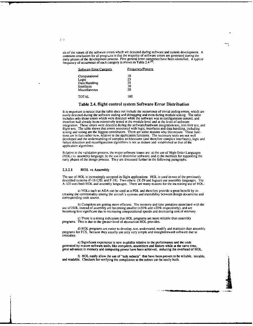
sis of the nature of the software errors which are detected during software and system development. Acommon conclusion for all progr,-ns is that the majority of software errors are generated during theearly phases of the development process. Five general error catcories have been identified. A typicalfrequency of occurrence of each category is shown in Table 2.4 1.
Table 2.4. flight control system Software Error Distribution
It is important to notice that the table does not include the occurrence of trivial coding errors, which areeasily detected during the software coding and debugging and even during module testing. The tableincludes only those errors which were detected while the software was in configuration control, andtherefore had already been extensively tested at the module level and at the level of softwareintegration. Those errors were detected during the software/hardware integration test, iron bird test, andflight test. The table shows that errors associated with logic, interfaces and data handling, includingtesting and voting are the biggest contributors. There are some reasons why this occurs. These func-tions are in fact rather new, relative to the application functions. The necessary tools are not welldeveloped and the understanding of complex architectures (and therefore complex interfaces), logic andfailure detection and reconfiguration algorithms is not as mature and established as that of theapplication algorithms.
Relative to the validation process, the major software issues are: a) the use of High Order Languages(HOL) vs. assembly language; b) the use of dissimilar software; and c) the methods for supporting theearly phases of the design process. They are discussed further in the following paragraphs.
2.3.2.1 HOL vs Assembly
The use of HOL is increasingly accepted in flight applications. HOL is used in two of the previouslydescribed systems (F-16 C/D, and F-18). Two others (X-29 and Jaguar) use assembly languages. TheA-320 uses both HOL and assembly languages. There are many reasons for the increasing use of HOL:
a) HOLs such as ADA can be used as a PDL and therefore provide a great benefit by in-creasing the commonality among the aircraft's systems and traceability between design documents andcorresponding code source.
b) Compilers are getting more efficient. The memory and time penalties associated with theuse of HOL instead of assembly are becoming smaller (<50% and <20% respectively), and arebecoming less significant due to increasing computational speeds and decreasing cost of memory.
c) There is a strong indication that HOL programs are more reliable than assemblyprograms. This is due to the greater level of abstraction HOL provides.
d) HOL programs are easier to develop, test, understand, modify and maintain than assemblyprograms for FCS, because they usually use only very simple and straightforward software due tocriticality.
e) Significant experience is now available relative to the performance and the codegenerated by mature software tools, like compilers, assemblers and linkers while at the same time,great advances in memory and computing power have been achieved, reducing the overhead of HOL.
f) HOL easily allow the use of "safe subsets" that have been proven to be reliable, testable,and readable. Checkers for verifying the compliance to the subset can be easily built.
-it
2-11
It is anticipated that the trend towards increasing use of HOL will continue. The main problem withthis approach will certainly be the validation of the compilers (with respect to the safety) and that of thereal-time kernel. However, specific parts of the software (I/O, interrupts, handlers) could still bewritten in assembly for some years and be integrated with other parts written in HOL.
2.3.2.2 Dissimilar SoItware
The effects of using dissimilar components and functions was discussed in previous paragraphs of thispaper. In this paragraph the effects of dissimilar software, in particular, are analyzed. Dissimilarsoftware can be used in three ways:
a) as a failure detection mechanism. In this case results from both versions of software arecompared periodically and, in the case that the results differ by more than certain values, a faultcondition is detected. In that case, reversion to a back-up control mode must be made, which does notutilize either of the two software versions:
b) as a back-up control mode. In this case, if a common failure is detected in the primarysoftware, reversion is made to the alternate version. Alternate software versions typically provide limit-ed capabilities only. The F- 16 C/D flight control system is an example of this application.
c) as a way to achieve software fault tolerance. In this case redundant, but not identical,versions of the software are implemented for detection of software failures and for providing alternate,usually degraded, computational paths. Recovery blocks and N-version programming are two tech-niques used for these purposes.
For the A320, points a) and c) described above are addressed by control/monitor channel implementa-tion, as well as ELAC/SEC architecture.
2.3.2.3 The Early Phases of the Development Process
Clear evidence exists that the software errors which are most difficult and costly to detect are oftenintroduced early in the development process. This points to the need of tools, techniques andmethodologies capable of effectively supporting the specification and design phases. The entire designand validation process must be supported by integrated development environments, which includespecification and design languages with powerful diagnostic capability, and which are easy to use.
It is extremely important to define, as early in the development cycle as possible, design disciplineswhich make the software traceable, testable, maintainable and easy to understand. Design and codingstandards must also be established, like:
a) limiting the complexity of the smallest software blocks within the human analysiscapabilities; complexity depends mainly on the number of embedded constructs (if-then-else, loops,gotos....) and also on the number of lines;
b) avoiding design features or coding constructs whose dynamic behavior is untractable orwhich may result in memory overflows (either in the stacks or data allocated areas) or timing overrun;complex event-driven schedulers, dynamic memory allocation, recursive/unlimited embedded callsshould therefore as much as possible be banned for FCS applications;
c) enforcing the use of "robust" programming; this may include reasonableness testingwithin the operational software or exceptions handling.
2.3.3 Sensor/Actuator Issues
The fault tolerance and reliability requirements of advanced flight control systems often require redun-dant configurations of critical sensors and actuators for supporting functions required for continuoussafe flight and landing.17' Not all sensors and actuators have the same level of criticality, so it is rathercommon that different levels of redundancy are used within the same flight control system. Therequired level of hardware redundancy is also affected by system level considerations, like the functionof analytical redundancy which might exist among different groups of sensors or actuators, and theavailability of back-up systems.
Analytical redundancy has been employed at the sensor plane. The objective is to provide a synthesizedfeedback signal, in the case of failure of the primary sensor suite, by analytically combining (or fusing)information from other sensors. Functional redundancy is employed at the aircraft effector plane. Theobjective is to generate forces and moments about some control axis, in the case of failure of theprimary effector, by appropriately modulating a combination of other operational effectors. Thefunctional redundancy among many effectors existing in advanced vehicles makes this approachfeasible. Another good example of functional redundancy is provided in roll control of the A320: rollcontrol may be achieved via ELAC (ailerons) and SEC (spoilers), with reduced efficiency, if ELAC'sor SEC's are lost.
The availability of analytical and functional redundancies has profound effects in the validation of flightcontrol systems. They might reduce the criticality of some sensors and effectors and correspondinglydecrease the validation effort of the equipment involved. They might also reduce the hardwareredundancy needed for satisfying specific fault tolerance requirements. In this case additionalvalidation effort will be required to demonstrate the availability and the effectiveness of thoseredundancies.
It is important to note that, although a sensor or an actuator is often referred to as having a certain levelof redundancy, that level of redundancy often applies only to some, not all, of the elements (and/orfunctions) that the equipment comprises (and/or performs).
As an example, the sensing component of an Linear Variable Differential Transformer (LVDT) sensor,could be single or dual. The electrical paths to the Flight Control processors, however, could be quad,in the case that the LVDT interfaces with a quad flight control system configuration. The redundancyof the first control stage of an hydraulic system might also be quad, to reflect the flight control systemarchitecture, but the main ram and the hydraulic supply might be only dual. In most flight critical sys-tems it is imperative to eliminate all features where a single point failure can cause a loss of control. Inextreme cases where such a point cannot be eliminated the regulatory authorities will insist on a rigor-ous analysis and demonstration that no realistic failures can occur at that point.
Many considerations determine the final configuration of the control systems of an advanced aircraft.The objective is often to find an acceptable design among many different, and some time conflictingrequirements.
REFERENCES
[1 ] Rediess, H.A., and Buckley, E., "Technology Review of Flight Crucial Flight Control Systems",NASA CR 172332, April, 1984.
[2] a Harschburger, H.E., Glaser, B, and Hammel, J.R., "Backup Modes for the F/A-I 8 DigitalFlight Control System", AIAA 84-2622, 1984
2 b "Landis, K.H., and Glusman, S.I.; "Development of ADOCS Controllers and Control Laws.",NASA CR 177339, July, 1984.
2 cRamage, J.K., "AFTI/F-16 Automated Maneuvering Attack System Configuration and Integration,Proceedings of the IEEE 1986 National Aerospace and Electronics Conference, Dayton, Ohio,May, 1986
2 c Whitaker, A, and Chin, J., "X-29 Digital Flight Control System", AGARD-CP-384, October, 1984
2 d Hillis, A., "A310 Slat and Flap Control System Management and Experience", 5th Digital AvionicsConference, Seattle, WA, November, 1983
2 eMarshall, R.E.W., Snelling, K.S., and Comey, J.M., 'The Jaguar Fly-by-Wire DemonstratorIntegrated Flight Control System", Proceedings of the United States Air Force Academy AdvancedFlight Controls Symposium, 198 1.
2-13
2 fFlapper, J.A., and Throndsen, E.E., "LI011 Flight Control Systems", Integrity in Electronic FlightControl Systems, AGARDograph No. 244, 1977.
2 g F-16A Anderson, C., "F-16 Multinational Fighter", AGARD-AG-234, November,1978
2 h Comey, J.M., 'The Evolutiop of the EAP Flight Control System. Presented to the InternationalSymposium on Aeronautical Science and Technology of Indonesia, 24-26 June 1986.
2 iA-320. Aviation Week, May 18, 1987, p. 41-45
2jKubbat, W., "A Quadredundant Digital Flight Controls System for CCV Application." Impact ofActive Control teclnology on Airplane Design, AGARD-CP- 157, June 1975.
2 k Szalai, K.J., Felleman, P.G., Gera, J, and Glover, R.D., "Design and Test Experience with a TriplyRedundant Digital Fly-by- Wire Control System, AIAA 76-1911, August, 1976.
[3] Harschburger, H.E., Glaser, B, and Hammel, J.R., "Backup Modes for theF/A-18 Digital Flight Control System", AIAA 84-2622, 1984
[4] Burton, R., Kneeland, Rabin, and Hansen "Flight Testing and Development of the F/A-18 DigitalFlight Control System", AGARD-CP-384, Toronto, Canada, October, 1984.
[5] Smith, R, "Flight Clearance of the Jaguar Fly-by-Wire Aircraft", Royal Aeronautical SocietySymposium, April, 1982.
[6] Hecht, H.M., "Trends in Software Reliability for Digital Flight Control" NASA CPR 166456, April,1983.
[7] Fault-Tolerance Design and Redundancy Management Techniques,AGARD-LS- 109, September, 1980.
LY T L ne r ar ab iReonia l T ro n r A t i u e chit d a tn ric a l CS ugeqve
Aat Gyros do
P1 * Static Fleght
Oc * Dynamic pleasur
Fitre24 /- s -h ontr Syte FuAin iga
UH AnP:=:
2-17
AHRS iLR W0Legend sev c.(Litton)iSA Integrated sroat
(F-16, dual tandem) Air data system I Sensor system I I
JRosemount) I (Honeywell) I
Vanes i~ j C
ELSJ Cockitan
control Nose Sie Tota
oompte ep
% f" Flaerons, ihaixe
F2r geare lead FlghabntolSstmychmai
QMPLAV Umf
PLO"' CO.WIOL
MO. IIA.tfwk
CoklotoLPW* L
pow&*
PLOOT CWTIACILcobvfilm a
taf If-LINOft
P41ck st U , "oMOLL M. Apo
CTuAlcmOADn PEDAL
Kw.m
P-IC- AND AClualokVAW lph. I..Vt Plo
MON.100 O'b.,10-0, f
ACV-PWDNAt MKS
MULL Ich ACTLiAmmAND Wo ORMOV ANDWATI OWN" "MaTomCOMftTfS
AND
JIM.
nowr CO(MM
pig
mOualca
A aftak ctmo cm
Kohl" TOL
Figure 2.6 FRW Archileclure
HydrauliC actuators
LEFT
NORM Electr:c
Autopilot -
commands ELAC (2
com rids
THS Trimmable horizontal Hydraulicstabilizer
ELAC Elevator and aileron B Blue systemcomputer G Green system
SEC Spoiler and elevator Y Yellow systemcomputer
Figure 2.7 :%32o Pitch Control
Hydraulic
actuators
RIGHT
Autopilot-------. Aileronscommands 2LF
LF
-3) Spoilers 2,3,4 & 5SidestickSE
commands
Figure 2.8 A320 Roll Control
Travel limitation M ( Hydraulic
----- Mech.stop Gatommands FA Yaw damper G ray
yaEomndL AC
Rudder trim
Rudder Rudder trim _.feel Rudpedals feel )Rudder
M Motor actuator Hydraulic
B Blue systemFAG Flight augmentation G Green system
computer Y Yellow system
Figure 2.' .9320 Yaw Control
I!
3-1
CHAPTER 3
SOA GENERIC DEVELOPMENT AND VALIDATION PROCESS
3.0 Introduction
The validation process is embedded in a complex series of events making up the development of theflight critical control system (FCCS), which is only part of the flight system and total airplanedevelopment process. A well organized and systematic airplane and flight system development processis a necessary foundation for a successful and efficient validation program.
The purpose of this chapter is to provide a top level description of the FCCS validation process and itsrelationship to the overall airplane and flight systems development cycle. It serves as a guide andbackground to chapter 4, which contains a very detailed description of the state-of-the-art tools.techniques, methods, and approaches used in the validation of the FCCS.
There are many ways in which systems can be developed and validated and these ways change withtime. The method described in this chapter is a generic process, based on the experience of themembers of the working group who have been associated with the development and validation of mostof the flight critical control systems produced in Europe and USA during the past two decades.
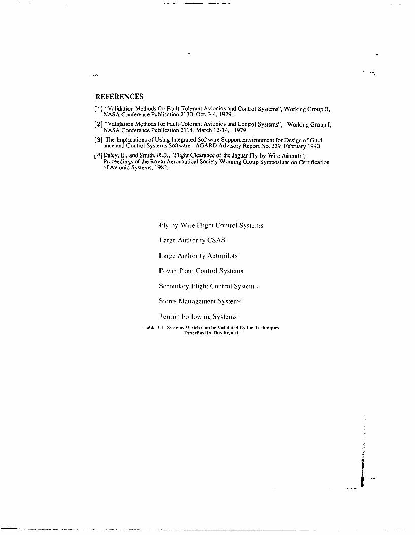
It should be noted that in addition to the application which is the focus of this report, the methods usedto validate FCCS's are sufficiently general and rigorous that they can be used to validate other flightcritical systems such as those given in Table 3.1.
3.1 Relationship of FCCS Development to the Military Aircraft Life CycleThe top level requirements for the flight control system of a military aircraft are derived from the systemrequirements associated with the aircraft/weapon system mission and operating requirements. Therelationship between the development of the airplane and the flight control system is shown in Table 3.2,as characterized in the U.S. A more detailed description of this military aircraft life cycle model, andhow the flight control system development is embedded in it, is contained in Appendix 3.1.
3.2 The Life Cycle of a FCCS
Figure 3.1 shows the phases in the life cycle of a typical FCCS It l. The process is sequential and the toplevel requirements are systematically converted into detailed designs with validation providing thefeedback to check against errors and omissions.
The system is validated by showing that the production system meets the Goals and Requirements de-fined at the start of the process. This can be done by checking that the results of each phase meets therequirements placed on it by a prior phase. e.g., the Development Specifications may be validated bychecking that they meet the Systems Specifications. Alternatively they may be validated in part bychecking that the design meets the top level Goals and Requirements.
Various methods are used to validate the system in a particular phase. In the earlier phases validationmay be based on .bstract models, but as the project matures, the models become more concrete and theresults of tests on prototype and production equipment are used for validation. Figure 3.2 lists thegeneral categories of the methods used in each of the phases (also from Ref 1). Figure 3.3 shows howthe validation process can be considered as a feedback path checking the operation of the forwardpath121.
A clear hierarchy in the development and documentation process is essential for a successful validation
3-2
program. The documentation must be structured so that all the requirements are explicitly stated.Furthermore, the documentation should avoid confusion by being so organized that requirements arereferenced only once. One method of providing this hierarchy is shown in Figure 3.4, based on DOD-Std 2167A. The following definitions are appropriate:
a. System Spgcification - A document which states the technical and mission requirements for asystem as an entity, allocates requirements to functional areas (or configuration items), and defines theinterface between or among the functional areas.
b. Development Soecification - A document applicable to an item below the system levelwhich states performance, interface and other technical requirements in sufficient detail to permit de-sign, engineering for service use, and evaluation.
The key point here is that there should exist a clear and unambiguous relationship between the variousspecifications, development steps, and documentation items to provide a traceable and continuousflowpath of activities. This top-level view will provide a structure for the entire development andvalidation program which can be used by all parts of the organization.
3.3 Goals and Requirements
The Goals and Requirements are the overall attributes of the system; they include the mission-relatedrequirements as defined in highest level staff targets, or statements of need. They also include therequirement to meet the appropriate national specifications (e.g., Mil Std 8785). Overall safetyrequirements are included, based on national specifications (e.g., Mil Std 882) or on historical data withappropriate extrapolation. The Goals and Requirements reflect the improvements in systemperformance which are possible due to advances in technology.
A semi formal statement of the Goals and Requirements is a valuable aid in the initial phases of aproject: it promotes discussion, reduces ambiguities and highlights omissions. It acts as a focus for theinitial discussions and as a criteria against which to validate subsequent phases. The validation of theGoals and Requirements can be accomplished in part by carefully comparing them against the missionscenarios, against historical data and against similar systems.
3.4 System SpecificationThe System Specification is a key document in the design of a FCCS. It is a statement of the functionswhich the system must provide and forms the basis for the subsequent detailed design and becomes themodel against which the system is validated. The system specification usually follows a standard formatand includes a definition of the context in which the system is to operate, a statement of the integrityobjectives. Figure 3.5 is a typical format. The validation of the Functional Specification isaccomplished by mapping it out against the Goals and Requirements by analysis.
It is possible to introduce semi formal methods to improve the coverage and consistency of the systemspecification. Software tools are now available to help in the generation and maintenance ofspecifications using semi formal methods.
3.5 Development Specification
Once the Functional Specification is established, a set of Development Specifications are produced.There will be many such specifications to cover various areas. A list of typical DevelopmentSpecifications is given in Figure 3.6.
Development Specifications can be validated by checking that each of the functional requirements iscovered by the specifications and that each of the requirements in the development specifications isconsistent with the functional requirement. Again, this process can be facilitated by software tools usingsemi formal methods based on a mixture of text, graphics and computer language syntax.
In a broader interpretation development specifications include all the design definitions and as such theyare models of the system which can be validated by analyses such as a failure modes and effects
I
analysis, to check that the design does meet the System Specification. Some excellent approaches have
bcn suggested and developed for project documentation"] .
3.6 Implementation and Prototype
Figure 3.7 shows the activities which lead to the prototype implementation. The control laws determinethe handling qualities of the aircraft, and the structure of the control laws determines the levels ofhardware and software redundancy necessary to meet the integrity and availability criteria. Thus, thedesign of the control function becomes the central activity which defines the complexity of the systemsand the reliability level required for each of the facilities within the system. The hardware designer, thesoftware designer and the redundancy management designer cooperate to implement the specifiedcontrol function.
The control law validation process uses a variety of modeling/analysis techniques (see Figure 3.8) all ofwhich are based on aerodynamic data which must be comprehensive and accurate. Rigorous testing ofmodels and prototypes is necessary to derive this data. The validation of these aircraft models is criticalto the ultimate safety and performance of the flight control system.
Control laws in modem flight control systems are implemented in digital computers using softwarealgorithms. The task of designing hardware with the capacity to meet all the requirements consists of awhole series of activities ranging from architectural studies, through stress and tolerance analyses, toFMEA's. Designs are checked by analysis and prototype testing.
The production of software is equally complex and stringent; measures have to be taken throughout thelife cycle to ensure that the integrity of the .ortware meets the requirements. Figure 3.9 illustrates atypical set of activities associated with the software development process.
It is necessary to check the integi, ,, of the hardware and software to ensure that the developmentspecifications are met. Varioi rnvi:iods of testing are used as the test phase moves from simulation tolaboratory models, to bencl~. rings/iron birds, and finally to prototypes. The match with the realworld improves with each step.
Test benches which allow the system elements to be interconnected, powered and stimulated withsimulated inputs and outputs are used to check the detailed operations of the system. Although at eachsuccessive stage the testing becomes more realistic, the granularity of the testing becomes coarser. Thusthe later phas,-s of validation rely on the earlier phases for fine grained validation.
Rigs/iron birds arc the next stage in the progression to complete systems integration and validation. Inmany FCCS development programs, the rigs/iron birds have been the key validation tools. They havecombined representative hardware including cockpits, actuators using hydraulic systems withrepresentative geometry and loads, flight control computers and sensors. They have the capability tocheck out the interfaces between units and ensure compatibility. They also have capability to trigger thesystem to reconfigure and hence test the redundancy management.
On many rigs it has been possible to perform pilot-in-the-loop simulation and thus validate many of theaspects of the handling qualities and pilot interactions resulting from system reconfiguration.
3.7 Prototype Aircraft
There is a clear trend toward conducting a larger amount of work on hot benches and rigs, but thereremains a significant amount of testing that must be carried out on the prototype aircraft to ensure trulyrepresentative conditions. This includes check of interaction between systems, effect of aircraftstructure on control system resonances, electromagnetic shielding/interference effects, power transients,cooling system performance, and other elements which are sensitive to the actual hardware installation.
The production of the evidence to support the request for first flight clearance is a key stage in thevalidation. This is a large and complex process and inevitably deals with a vast ran e of predictions andjudgments. Figure 3.10 shows the process used to validate the Jaguar FBW system Al.
Once the first flight is completed a whole new set of data becomes available which can be used to check
out these predictions and judgments. Flight testing of prototypes is structured to gradually expand theinformation available and to check that the requirements defined in earlier stages have been met.
3.8 Production System
The final stage is to ensure that the production system has and retains the same performance as theprototype(s). The major considerations are configuration control to ensure repeatability, routine checksto ensure that latent faults do not invalidate system integrity during the long periods of risk experiencedon production systems, and maintenance to ensure that the system is as designed/built.
To validate the fielded system it is necessary to maintain records of failures, maintenance actions,performance, and usage, to show that the productions system is performing in the way that the developerpredicted.
APPENDIX 3.1: A LIFE CYCLE MODEL OF A MILITARYAIRCRAFT
The following is a description of a generic life cycle model of a typical major military system, like anew aircraft. The model is consistent with the guidelines included in the System EngineeringManagement Guide which was published for the U.S. Defense Systems Management College. Theguide describes an integrated system engineering and management approach, including methodologyand tools, for defining the requirements, configuring and sizing the system, managing its developmentand verifying the capabilities of the design. It covers the acquisition and development process of anymajor military system from inception to operational deployment and use. For the purpose of thisdoument, the system is intended to be the entire aircraft. The FCS is a prime or critical item.
The life cycle of major DOD systems includes five phases: Mission Need Determination, ConceptExploration Phase, Demonstration and Validation Phase, Full Scale Development Phase, Production andDeployment Phase.
The first Phase, Mission Need Determination, is carried out by the government. If successful, approvalto proceed with the next phases is granted.
The Concept Exploration (CE) phase defines and selects promising system concepts for further analysis.Outputs include: definition of performance envelopes, preliminary alternate designs, feasibility studies,preliminary life cycle cost estimates, and a functional baseline. The major documents issued at the endof this phase are: a) a System Concept Paper (SCP) which contains a statement of needs, alternatedesigns with corresponding performance estimates, and a risk assessment analysis; b) a SystemsRequirements Review (SRR); c) a functional baseline which states the technical and missionrequirements for the entire system as a single entity (such as the aircraft); d) a Request For Proposal(RFP) for the next phase, which contains the functional baseline (Type A specifications), managementapproach, and the Statement of Work (SOW) which describes the scope of the contractor effort. Duringthis phase, major subsystems are identified, and preliminary performance requirements are developed.For example, several concepts of the FCS, engine, avionics, etc., may be developed and the performancedefined. A SRR may be conducted at the end of this phase or soon after initiation of the next phase, Apreliminary version of the Test and Evaluation Master Plan (TEMP) document is developed in thisphase.
The Demonstration & Validation (D&V) phase main objective is to determine whether to proceed withthe Full Scale Development (FSD). Several trade studies are conducted for evaluating the relativemerits of competing concepts which were defined in the previous phase. The most promising concept isselected and the prime and critical Configuration Items (CI) are defined. A major output of this phase isthe definition of the "allocated baseline" which satisfies the mission requirements established by thefunctional baseline by allocating specific requirements to the identified Cl's. As an example, the FCSmay be partitioned in the FCC, software and hardware, actuation system, sensor suite, pilot interfaces,
etr. Some of them may also be defined as a Cl, based on their complexity and criticality. Thefunctional baseline is finally allocated to each Cl. Assessment of achievable performance, life cycle costand technical risks are performed. High risk items and all items for which a proof of principle andcomponent demonstration test is beneficial, may be prototyped. A System Design Review is conductedat the end of this phase which validates the allocation of requirements to the Cl's. The activitiesperformed in this phase are supported by analysis, simulations, emulations, and prototypes. The TEMPdocument is updated to include the requirements for all major testing equipment and facility. TEMP,however, still primarily addresses system test requirements, rather than the testing requirements ofindividual Cl's. A detailed test plan is also developed which includes methods for validating flightcritical functions and Cl's.
The Full Scale Development (FSD) ohase primary objective is to develop and to demonstrate the designof the system concept selected in the previous phase. During this phase a small number of prototypeaircraft (usually not more than three) are built. The development process of the test facilities for theindividual CI's and for the entire system is conducted concurrently with the development of the Cl'sconsistent with the test requirements established in the previous phases. They may include thedevelopment of dedicated laboratory systems, real time simulation environments, and even an iron bird.The iron bird is a most realistic duplication of the actual aircraft environment including, but not limitedto: a) physical dimensions, b) aerodynamic, mechanical, electrical and thermal loads; c) hydraulic,pneumatic and electric power, d) electrical, hydraulic and pneumatic connections.
The first step of the process of building the Cl's is the development of the preliminary system designwhich ends with the successful completion of the Preliminary Design Review (PDR). The preliminarydesign defines the development specifications (Type B specifications) of the Cl's so that detail designprocess can initiate. At the end of that process a Critical Design Review (CDR) is then conducted. TheCDR encompasses all Cl's, and most importantly the interfaces among Cl's, and produces developmenttype specifications. Up to, and and including, CDR the vehicle is a paper airplane only, althoughlaboratory prototypes of many subsystems and components may have been built for supporting theevaluation process and providing proof of principle. After successful completion of CDR the InterfaceControl Documents (ICD) are finalized, the system design is frozen, and the development process ofprototype Cl's, like the FCS, start. Once developed, the Cl's are tested in dedicated laboratoryenvironments which simulate the entire range of operational conditions. The Cl development processends with successful completion of two audits: the Functional Configuration Audit (FCA) and thePhysical Configuration Audit (PCA). FCA is performed to validate that the Cl has achieved the requiredperformance and functional characteristics. PCA is performed to validate that the Cl "as built" conformsto the technical documentation, and it establishes the Cl baseline.
As the Cl's are baselined, they are integrated within the system test facilities. At the completion ofSystem Integration Test, all Cl's are successfully integrated and demonstrated, and a Flight ReadinessReview is conducted which, if successful, clears the way to the Flight Test Program. The Flight TestProgram is performed by flying the prototype aircraft, which have been assembled during the last phasesof the FSD. After successful completion of the Flight Test Program the aircraft is qualified foroperational service.
After the FSD, a Production Readiness Review (PRR) is held to verify that the system is ready to go intothe next phase. A design data package is then developed which includes production drawings. An RFPis then issued which includes detail product specifications (Type C specifications), which reference orinclude the entire design data package.
The Production and Deployment (P&D) phase primary objective is to produce systems according to costand schedule requirements. The Cl's are "build-to-print." Typically the first production Cl from maturetooling is subject to a PCA and a production baseline is established. Once a PCA has been successfullycompleted for all Cl's, a product baseline for the system is established.
REFERENCES
[1 ] "Validation Methods for Fault-Tolerant Avionics and Control Systems", Working Group II,NASA Conference Publication 2130, Oct. 3-4, 1979.
(2] "Validation Methods for Fault-Tolerant Avionics and Control Systems", Working Group I,NASA Conference Publication 2114, March 12-14, 1979.
[3] The Implications of Using Integrated Software Support Environment for Design of Guid-ance and Control Systems Software. AGARD Advisory Report No. 229 February 1990
[41 Daley, E., and Smith, R.B., "Flight Clearance of the Jaguar Fly-by-Wire Aircraft",Proceedings of the Royal Aeronautical Society Working Group Symposium on Certificationof Avionic Systems, 1982.
Fly-hy-Wire Flight Control Systems
Large Authority CSAS
L.arge Authority Autopilots
Power Plant Control Systems
Secondary Flight Control Systems
Stores Management Systems
Terrain Following Systems
lahle 3.1 S.stes% ,hich ('an be Validated It% the TechniquesI Described in Thi, Report
tI ....
3-7
AIRPLANE LIFE CYCLE FCS DEVELOPMENT
CONCEPT DEVELOPMENT Study several configurationsCONCEPT DEVELOPMENT Conduct trade studies
Define and select promisingvehicle and systems concepts
r- - Select most promising FCS configurationsI DEVELOPMENT AND VALIDATION - Allocate functional requirements to FCS
and major FCS Configuration Items (Cl's)
Determine whether to proceedto full scale develpment
Develop, test, evaluate, validate individual Cl'sFULL SCALE DEVELOPMENT iIncremental laboratory integration of Cl'si _ _ _ _Integration of FCS with other aircraft systems
on rig, iron bird, and on aircraftDevelop and demonsftratevehicle design
PRODUCTION AND DEPLOYMENT Develop and quality production versionsof FCS hardware and software
Produce vehicle to cost schedule
Table 3.2 Relationship of Flight Control System Development to Airplane Life Cycle
All Steps are iterated until fro07en
VALIDATION ACTIVITIES
Goals andRequirements
System D~oes functional specificationSpecifications meet the goals and requirements ?
D~evelopment Does the design meetSpecifications the functional specification?
iiplceentationi and Does the implementation meetProlotype System the design specifications ?
ProdutionDoes the production systemsysicillagree with the prototype ?
FieIled Does the fielded system'sSystem behavior agree with the
production system behavior ?
Remainder of Life Cycle
Figure 3.1 - Digital System Life Cycle
3-9
Goals andRequirements
SystemSpecifications
DevelpmentBench Test, Simulation,
Sccificat ions Engineering Model Analysis
"llot-Bench" Tests, Ground TestsImiplemnentationi and( in the Aircraft, ExperimentalPrototype System Flight Tests
ProdutionCertification Procedures
FieldedWell-Defined Maintenance,SystemTrouble Reporting, and
Logging Procedures
Remainder of Life Cycle
Figure 3.2 - Digital System Li1re Cycle Applied to Aircraft Systems
Cumulative performanceGoals
o5 performance ------ Independent requirements
certification 04 operation ,03 simulators
o3 experimentsin-context requiremetts
'u pertormance o4 expenments l. h isto r
experimentIs.,and models Apoach
A2 FNIEA, CAD4Design specification
05 qual tests. 2 software/firmware verification 4n Implementation simulations F/W
appraisal appraisal and LRL FMIvEA IsetIFBite coveraize Tolerance Qualification
analysis analysis testing andinspection
Rel iabilitvanialysis Bum-in
figure 3.11) Ensuring SYstemn tntegrit%
4-1
CHAPTER 4
CURRENT METHODOLOGIES AND TECHNIQUES
4.1 Introduction
The purpose of this chapter is to present current methodologies and techniques used to validate a flightcritical system. Assessments of individual validation methodologies are also included. In Chapter 5, anassessment is made of the overall state of the an of validation of flight critical flight control systems.
Validation begins in the system requ'rements analysis phase and continues through the developmentphase and culminates in the demonstration that the final system complies with the system-levclrequirements defined prior to start of development. Figures 4.1 to 4.5 show a flight control systemdevelopment cycle based on European and U.S. practice
There am four basic types of validation activities:
Inspection - used for determining if the product (software, hardware, or integratedsoftware/hardware) as built, conforms to the applicable documentation, such as engineering drawings,flow diagrams, computer listings, user requirements, system specifications, etc. Inspection typicallyinvolves visual/physical examination or simple measurements.
Test - used to establish that the product functional characteristics conform to operationaland technical requirements. The process has a high technical content, and usually requires specializedtest equipment and formalized procedures. The product under test is stimulated with inputs to generatecontrolled responses which can be compared with predictions. Data generated by test is further analyzedto determine conformance with the criteria. Test passage can either be go-no-go, or be a result whichfalls within criteria boundaries.
Demonstration - used to show the customer and/or legal authority that the productfunctions as required within the operational envelope. Test passage is usually based on go-no-go criteriaestablished by the reviewing authority.
Analysis - used to show compliance with requirements, either to complement test, or toreplace test when test is not possible or practical. Data output is from simulation and analytic models.An important, but often difficult task is the validation of the models used in the analysis.
4.2 Development of the Customer Requirements Specification
The initial step in the development of an aircraft is the formulation of the customer's requirements whichdefine what is required of the aircraft. (The terms operational baseline, functional baseline, allocatedbaseline and product baseline are taken from Mil Std 2167). The user will usually have conducted aseries of studies which will have established the major characteristics of the aircraft and its systems toenable the aircraft to meet its operational goals. Normally these characteristics will be contained withinthe statements of need/staff targets, and later in the Program Management Directives/staff requirementswhich are the formal statements of the Operational Baseline. They are top-level requirements and do notprejudge how the system will be configured to achieve the requirement.
The Operational Baseline for the aircraft is usually written in plain language and often is based onpreviously defined operational requirements of the user. An assessment is made of the reasonableness of
the Operational Baseline, based on previous systems and experience, as well as on knowledge of thestate of the art of the various technologies to be incorporated in the new vehicle and its systems.
The operational baseline for the aircraft will include the following aspects which are directly relevant to
the flight control system.
a. the requirements for the handling qualities, ride qualities, and control characteristics
b. the definition of the flight envelope
c. the modes of the FCS required
d. the reliability, safety, and availability requirements
e. the maintainability and testability requirements
f. the growth potential required
g. the methods and standards which must be applied.
Since the Operational Baseline is a list of the customer's requirements it is necessary to ensure that allthese requirements are captured and combined with requirements from other viewpoints (e.g. design,manufacture, and certification), and then checked for completeness, consistency and traceability.Methods and computer-based tools are emerging to carry out these tasks in a systematic way. Theymodel the requirements, the interactions between them, and maintain traceability with subsequent designstages.
4.3 Development of the Weapon System Specification
The next stage in the process is the development of the Weapons System Specification. The customer'srequirements are studied and combined with candidate solutions in a series of concept developmentstudies, analyses and reviews.
While the emphasis in this phase is on the requirements, in some areas the requirements will be matchedwith a candidate design, and it is inevitable and desirable that the requirements and design be iterated toproduce a system design that is feasible and meets customer requirements.
The designers will study various configurations of aircraft and systems to determine how best to meet therequirements. Extensive studies involving all aspects of the system will be made and may requiredevelopment programs and prototyping.
These studies will include a preliminary assessment of the FCS functions and the major characteristics ofthe FCS, e.g. FBW or mechanical controls, authority levels, safety, reliability, availability, interfacewith other sub-systems.
The result of this phase is the material for the Systems Requirement Review which will validate that therequirements in the Operational Baseline have been transformed and elaborated correctly in the SystemRequirements documents. It is crucial that 100% traceability is maintained during this process, becauseof the significant impact that errors at this point can have on the subsequent system design process.
Studies will include an assessment of the technical risk of the configuration and the technology requiredfor implementation. The studies will determine what further development is required.
4.4 Development of the FCS Requirements Specification
The FCS Requirements Specification (FCS RS) is the entry to the FCS life cycle. It is formed by ananalysis (e.g. functional decomposition) of the weapon system specification (WSS); it defines thefunctions performance needed from the FCS to meet the WSS.
The FCS Requirements Specification is one of the series of sub-systems requirements specifications,
4-3
each derived from the WSS; other. include the Hydraulics Supply System Requirements, the ElectricalSystem Requirements, etc.
During the development of the FCS RS studies will be made of the interaction between the airframe andthe FCS to establish the levels of performance required, e.g. the level of instability that the FCS cancompensate (see Figure 4.6)
The FCS RS is validated by checking the functions specified in the FCS RS against requirements in theWSS and in the customer requirements.
Another form of validation is made by comparing the functions specified against those used on previousprojects and those developed in previous research and development programs. This limits the technicalrisk by reducing the technology increment. The validation activities will include a series of reviewmeetings between system design specialists to ensure that the various subsystem requirementsspecifications are compatible.
4.5 Development of the FCS System Specification, the Control Law DesignSpecification and the System Quality PlanOne method of proceeding with the development of a system to meet the FCS requirements is to split theprocess into 3 major activities: Control Law Development, FCS Development and System Qualification(see Figure 4.2). Each of these activities is controlled by a document derived from the FCS RequirementSpecification.
The control law development is specified in the Control Law Design Specification which groupstogether and amplifies what is required from the control laws and outlines the form of the design. Thisdocument is the basis for the control law development as detailed in the control law development plan.
The FCS System Specification outlines the total FCS. It defines the functions produced by the systemand the units which comprise the system.
The specification is the result of past experience, research, development and studies and analyses to findarchitectures, technologies and equipments which will meet the multiple requirements placed on theFCS. It will be influenced by the requirements of other systems, by the performance required, byresources, time scales and perceived technical risk.
Techniques used in this phase include:
" Hazard Analysis to determine the integrity needed in the various elements.
• Reliability Analysis to determine the reliability levels needed from theindividual elements to meet overall targets.
" Preliminary FMEA to determine the effect of failures of individualcomponents.
Validation activities in this phase check that the FCS System Specification does "flow down" therequirements from the FCS RS and that the resulting design is capable of meeting the customerrequirements. Independent assessment of the performance, integrity and reliability may be applied tovalidate the FCS System Specification.
The System Qualification Plan defines how the system will be qualified and includes the requirementsthat have to be satisfied, the methods used to satisfy them, and the support facilities required. This Planwill lead to the development of all the rigs, test benches, test equipment, and support environmentswhich will be required to accept, test and integrate the equipments which comprise the FCS.
4.4
4.6 Development of the Requirements Specifications for Processing, Sensorsand Actuation
Once the flight control system specification has been produced and verified, the next phase is to refinethe requirements and the design.
One method of organizing this phase which has proved to be successful is to convert the FCS SystemSpecification into the three major areas of Processing, Sensing and Actuation. This is shown in Figure4.7.
A preliminary design is developed which has an initial hardware layout together with an allocation offunctions to the three sub-systems. The characteristics of the resulting integrated system is determined,including the safety and reliability. The design is then checked to determine compliance against the FCSSystem Specification and the procedure is iterated until a satisfactory design/allocation is found.
As sybicmb bewine more integrated there is a major risk when moving from these functionalspecifications to equipment specifications since the functionality is determined by several differea piecesof equipment, and the effect of the combined tolerances in all the equipments has to be determined.
Reviews
It is important to note that the reviews at this stage are at a systems level and at a degree of abstractionwhich prevents detailed assessments or analysis. This tends to obscure some requirements and make itdifficult to effectively review and critique those aspects of the system. It is important to include systemsengineering staff with broad experience in these reviews, in addition to design specialists, because thesystem must be assessed at a level of abstraction which makes experience comparisons a key technique invalidating requirements. The baseline configuration validated at these reviews will become the formalrequirement for the system. It will cover all aspects including integrity, functionality, environment,performance, modes of operation, reversion capabilities, and methods of validation.
4.7 Development of the Processing Sub-Systems
One approach which has proved successful, and has become standard practice is to split the processingsubsystem into the three principal activities, namely hardware, software and test equipment (see Figure4.3). The development of the specifications for these three subsystems is based on an iterative process ofdesign and analysis in which draft specifications are produced, outline designs are developegI, andanalyses/tests are made to validate the subsystems specifications and the design against the systemspecification.
4.7.1 Development of the Hardware
The development of hardware for flight critical systems follows normal flight system hardware designpractice with extra attention being paid to the rigor and detail of the design and to the validation ofperformance and operation.
Hardware Specification
The major items in the hardware specifications are shown in Table 4.1. The validation of thisspecification will be routine in most areas; the detailed requirements will be checked for compatibilitywith the overall requirements as defined in the FCS system specification. However, in two areas ofvalidation, redundancy management and functional performance, special care is needed. In these areasthe functional capability required from the system depends on interlinked capability of the hardware andthe software. Thus it is necessary to validate a matched set of subsystem requirements. This requirementfor interlinking can be formulated in a separate specification of the overall capability at a more detailedlevel than the flight control system specification and then the subsystem can be validated against it.
4-5
Reducing Abstraction
While even at this stage, it is possible to leave the requirements general, and delay design until the nextstage, it is often better to base the subsystem specification on a specific implementation. This improvesclarity by removing abstraction and makes it easier to detect conflicts between requirements.
Validation Analyses
Validation techniques used at this stage to check the integrity of the system include FMEA, simulation,reviews, and Fault Tree Analyses (FTA). To quantify this analysis, these calculations are based oncomponent failure data such as Mil Hdbk 217.
Test Equipment Requireent
The hardware subsystem specification should define the test injection and monitoring equipment whichwill be required to verify that the system is performing correctly in normal and under fault conditions.
Purpose of Hardware Validation
The validation tests and analyses check the the following items against the subsystem specification:
Performance
- correct execution of the instruction set by the processor
- correct input-output data handling
-correct operation of the RAM and ROM functions
Integrity
- functionality of the redundancy management logic features implemented in hardware
- ability of the system to contain failures as predicted in the FMEA to meet the safety,availability and mainternance requirements
- operation of the unit under nortal and extreme conditions
- BITE coverage as required for integrity, as per the FMEA
- BITE coverage required for maintainability
Description of Hardware Validation
Representative hardware is tested in a controlled environment. A wide variety of tests are conductedusing special test software to check the operation of the hardware in nominal and extreme environmentswith inputs at nominal values and at extremes of the operating range. Sensitivities are measured andtolerances checked against the subsystem specification or against a new set of tolerance criteria resultingfrom analyses of the integrated system components. Operating characteristics especially checkedinclude:
- Correctness of operation
- Speed of operation
- Sensitivity to power supply variations
- Thermal profile of the design
- Mechanical integrity of the design
- Range of signal inputs
- Range of signal outputs
- Interface compatibility
Support Facilities
In order to support the development of the subsystems, specialized test and support facilities andequipment are required. Specifically, the support facilities must include-
- Hardware representative of the flight system (breadboard or brassboard)
- Software to exercise the computers with the facilities to change the software toaid diagnosis
- Test equipment capable of simulating the external environment and capable ofgenerating simulated failures in the computer. (A hot bench)
- General test equipment (logic analyzers, emulators, bus analyzers, scopes)
- Environmental test facilities for altitude, thermal, vibration, and ElectromagneticInterference (EMI)
4.7.2 Development of the Operational Flight Program
Software Specification
The major items in a software specification are shown in Table 4.2. Software specifications may be pro-duced using a program design language or a high order language to facilitiate the communication of de-sign intent, and to provide a systematic set of specifications.
Procedures/Methods
Since techniques have not yet been developed to quantify the probability of occurrence of software errorin a particular set of codes, it is necessary to control software reliability by defining the methods whichmust be used to produce it., hence the emphasis in the specifications on standards, procedures andstructures. Figure 4.8 shows the method used for civil aircraft as specified in DO 178A. There is now awide range of design methods available to support software development and the subsystem specificationcan be checked for compliance with the requirements of an appropriate method.
Software Testing
Testing plays a central role in the validation of software and the subsystem specification should besufficiently detailed to ensure that the appropriate level of testing has been specified. Where thevalidation of the subsystem software has been well thought out in advance, entry and monitor points canbe built into the software with little overhead to support subsequent testing.
Development of Software
The development of software involves the gradual refinement of the requirements within the specifiedstructure until code is produced. That code is produced as modules which are then thoroughly tested andintegrated into subprograms and finally into the total program.
I ..
4-7
Description of Software Validation Process
The two basic techniques used to validate software are extensive testing, and rigorous construction. Since100% testing is impractical, the rigorous construction methods are a vital part of the process ofdeveloping software for safety critical systems. Most of the safety critical systems developed in the pasthave used a combination of rigorous construction and extensive testing. The current trends in softwarevalidation are automated testing and the application of more formal methods.
Validation by Testing
Testing is done at various stages;
- Module level (on the order of 100 lines of code)
- Subprogram level (on the order of 40 modules)
- Program level (using a simulator on a host computer)
-Rig, or iron bird (Representative hardware with representative interfaces)
- Aircraft on ground
- Flight test
Module Level Test
Code reviews and module tests are used to check that the modules operate according to the module
specifications. Static analysis tools can check:
control flow
- data flow
- information flow
The verification of the modules will include:
- tests to ensure correct operation with a limited data set andanalyses to show that the setis representative.
- analyses to detect banned construction/instruction.
- analyses to ensure correct use of memory.
- analysis/testing to ensure operation within time budget.
- analysis of correct entry/exit procedures
- tests of robustness for out-of-limits data
In addition, some subsets of the software can be validated using formal proof methods.
Program/Subprogram level test
Software integration tests are used to check that the modules, when integrated into programs orsubprograms, operate according to the subsystem software specification.Validation at subprogram levelwill check the compatibility of the modules and in particular will check the flow of data between modules
and the overall control of the modules.
The other levels of testing involve hardware. The tests are structured to ensure that the software ischecked in all its modes, with a large set of representative data, as detailed in the following sections.
Program Validation
Once the whole program has been assembled it will be validated by testing and by analysis against thefunctional requirements as given in the subsystem specifications. These tests will include checks toensure that the software detects faults, isolates them and reconfigures the system as required by theredundancy management.
Automatic Testing of Software
The large number of data sets which have to be produced to check out a system can be generatedautomatically using special test software which usually resides in the test support system. The automatictest software may also contain a model of the functional requirements and use that model to generateanswers and tolerances. Automated testing facilities are used which calculate the inputs to be injected,calculate the required results and tolerances and produce test reports which highlight failures. Thistechnique is important to reduce schedule delays and costs particularly after modification.
Testing on the Host
Initially the software will be tested remote from the flight hardware using a host faci".. .'ypically aminicomputer is used with a specially developed test harness which allows the progr. , to check out thesoftware modules with a thorough set of test cases, then to integrate the modules into subprograms andtest them at that level. The final stage on the host is to assemble the complete program and test it.
The level at which the testing can be done depends on the size of the software. Simulators which checkoperation at register level are inevitably slow (typically 100 times real time) and the test data produced isimmense.The combination of text values required to check a system forces the engineer to split the taskinto parts which have a much smaller number of inputs and outputs. He then tests those parts inviduallyand then tests thelinks between the parts. Thus the fine grain operations of the system can be tested.Clearly this form of testing does not replace the need to test the total system which gives an overall butcoarser grained text. Hence the emphasis on testing to provide proven modules and then tests to checkcorrect interaction.
Validation by Rigorous Construction
Many of the aids to validation are based on the premise that it is better to show correctness by ensuringthat rigorous methods are used in the construction of the software.
The techniques used in this type of validation include:
- Formal specification (Defining the requirements and the sytem in annotationbased on mathematical methods, and then proving the system meets therequirements)
Structured Analysis (Breaking down the requirements using a structuredmethod)
- Static Analysis (Examination of the code to ensure sound programming rules arefollowed)
- Program Description Language (Using a "formal" language to
define requirements)
- Dynamic Analysis Configuration Control (testing by exercising the code)
4-9
Support Facilities
The principal support facilities in this stage of development are principally those related to the softwaresupport environment:
-editor- linker- loader- assembler- compiler- debugger- simulator- test harness- test case generators- static test tools- semantic checkers- proof checkers- test coverage analyzers
4.7.3 Development of the LRI Test Facility
The development and validation of test equipment follows closely the process for the development offlight hardware with the appropriate modification for the different environmental, cost, and integrityrequirements. The validation of the test equipment consists of tests and analyses to establish thatperformance is correct and is representative of the real world it simulates.
Test Facility Specification
The principal items in a test equipment specification are very similar to those of the hardwarespecification given in Table 4.1; in addition, the test equipment may have its own software which willrequire specification as contained in Table 4.2
The subsystem specification will define the test injection and monitoring equipment which is required tovalidate system performance in normal and under fault conditions.
The validation of these specifications will be by comparison with the FCS specification and with thespecifications of those units which it is simulating. The latter will require comparison of performancefigures or analyses to demonstrate equivalence.
Software for the Test Equipment
The development of the software for the test equipment is validated as described in Par. 4.7.2 whereappropriate. Where the test equipment software does not impact the integrity of the system, then the testanalyses are restricted to those necessary to ensure test equipment performance. An emerging practice isto maintain configuration control of the test equipment and software to the same level as that done forflight systems, often using the same configuration control boards and documentation. This is done inrecognition of the criticality of maintaining the integrity of the systems used to validate flight criticalsystems.
Simulating the Interfaces
The test equipment required for flight critical systems consists of interfaces, processing sections,monitoring facilities and test injection facilities. It has to simulate the interfaces in a sufficientlyrepresentative way to make rigorous testing possible.
One important area is the fidelity of simulation of the test rigs. Test rigs must simulate aircraft systemsexternal to the flight control system. The accuracy of this simulation will influence the accuracy of theresults of the tests. Special tests and test rigs to check the simulation may be needed, e.g., loadssimulation for actuators, motion simulation for sensors, pneumatic simulation and bus traffic simulation.
4-i1)
4.8 Integrating the Hardware and Software
Once the hardware, software and test equipment have been proved as separate systems they are integratedto check compatibility. A series of tests are undertaken to check the characteristics listed in Table 4.3against the system and subsystem specification.
Representative software is fitted into representative hardware. The computers are then connected to atest bench which supplies power, simulates the external environment and provides monitoring andrecording equipment. A typical hot bench configuration is shown in Figure 4.9.
The operation of the LRI is then validated by tests based on the structure of the computer and by testsbased on the functions required of the system.
Support Facilities Required
- Hardware representative of the flight system (breadboards, brassboards)
- Software representative of the flight system to operate the computers but with extracapability to aid diagnosis.
- Test equipment capable of simulating the external environment and capable ofgenerating simulated failures in the computer.
- General test equipment (logic analyzers, emulators, bus analyzers, scopes)
- Software development environment
- Editor, linker, loader, assembler, compiler, debugger,simulator, test harness, etc
- Host computer with facilities to interact with thetarget computer
- Software analysis tools
- Facilities to change the target computer memory
Assessment
As is the case for the hardware-alone validation, the integnted hardware/software tests are a powerfulmethod of checking that computers operate as per the design specification. The integratedhardware/software tests involve a lot of equipment, some of which may be still undergoing change.Hence it is often difficult to separate problems and double faults are much more difficult to resolve thansingle faults. These integrated tests may be used to provide the evidence to support some of the moredifficult analyses, particularly the FMEA and FTA.
The effectiveness of the BITE may be checked by a series of representative tests, which provides supportfor the predicted coverage values, and also demonstrates the annunciation of detected faults.
Emulation
During the integration of the hardware and software it is often necessary to check the operation of theprocessor at a detailed level (e.g., internal register transfers). In many processors, access is not availableto that information without adding special software. However, hardware emulators are available whichsimulate the operation of the processor and give the engineer visibility into the internal functioning of theprocessor. This is a valuable aid to testing system operation and may be used to validate hardwarearchitecture as well as detailed software operation.
4-11
Power Transients
One of the major difficulties in fly-by-wire systems has been the problem of handling power interrupts.The basic problem is that the duration of the power interrupts which was acceptable for older generationsystems is larger than the duration of the "hold up" c-,acity that can be built into the units. Thus specialpower supply systems with shorter power interrupts have been developed. However, there are situationsin which power may be lost for sufficiently long periods that computer operation stops or becomesunreliable. To cope with such situations special circuits and software are designed into the systems.These mechanisms must be specifically validated during the hardware/software integration tests.
4.9 Integrating the LRI's to Form a System
The process of integrating the LRI's of the FCS is a gradual one which can be split into phases ofincreasing system coverage. Figure 4.10 illustrates one method and shows how LRI's are accepted,integrated with other LRI's and then tested on an iron bird. It also shows the specifications against whichvalidation is performed and the phasing of open loop and closed loop testing.
Configuration Control
Strict configuration control must be established and maintained for the flight-qualified articles, includingall software, as well as test stations and the aircraft system configuration. Identification of allcomponents not qualified for flight but needed for testing must be traceable so that they can be trackedand replaced with safety of flight (SOF) rated components before first flight For flight critical elements,100% traceability of all actions taken regarding these systems is required. Discrepancy reports, testreports, change requests, change documentation, qualification test results, and clearance for flight mustall be tracked precisely so that equipment or software not cleared for flight use is not able to creep intothe flight system.
Integration of Subsystem Interfaces
Each individual interface within the overall flight-critical system must be validated in the properenvironment prior to testing the entire system. Examples of the significant interfaces that must beexercised include the computer/actuator interfaces and the interfaces between sensors, controllers, andcomputers.
Computer/Actuator Interface Testing
Actuator Integration Test Stations which are powered by appropriate hydraulic pressure and capacity andan electrical signal which is conditioned by and compatible with the computer is essential in riskreduction. This is to insure that the actuators and control surfaces perform as required and in conjunctionwith the computer, electrical, and hydraulic power prior to the actual integration of these components onthe aircraft. The actuator control logic must be used in conjunction with the built-in-test development toassure that it is working before the integration begins. Figure 4.11 illustrates the actuation subsystemvalidation interfaces. The essential actuation system validation task is the definition of actual loads onthe control surface which affect surface deflection and rates. The solid arrow lines indicate the validationboundaries which can be accomplished on the ground. The dashed arrow lines indicates the validationtask that must be accomplished in flight.
Sensor/Controller/Computcr Interfaces
The physical design and mounting of the sensors and controllers must assure that each of these units isrigidly supported by aircraft structure and are serviced by appropriate electrical control signals.Provisions to check the built-in-test must be worked in conjunction with the computer hardware andsoftware logic. Developing this capability early is essential so that it can be used to diagnose problemsthat will be encountered during the integration process on the aircraft. Fig ure 4.12 shows the validationstructure for an air data probe, and Fig 4.13 shows the structure for a rate gyro/accelerometer assembly.
In the case of a sensor subsystem, such as an air data probe, the challenge in the validation process is to
4-12
provide a representative stimulus to the system on the ground. Ground models cannot adequatelyrepresent the flow field actually encountered in flight, with current technology. The solid arrows showvalidation steps that can be accomplished on the ground; the dashed arrows show the validation that mustbe accomplished in flight.
Iron Bird development
The extent and actual design philosophy of the "iron bird" is very much system design configurationdependent. The iron bird is an integration tool that permits early resolution of certain types of problemsrelated to hardware mechanical and structural arrangements. The iron bird typically includes dynamical-ly faithful such control surfaces and actuation connected with control elements and hydraulic andelectrical power supplies. Figure 4.14 shows a typical iron bird arrangement and its interfaces. An ironbird laboratory usually has the following features:
- interface to an avionics laboratory via a data bus- 3-axis rate table for gyro stimulation- aircraft or ground hydraulic pumps- landing gear rig area- flight control computers with test sets- actuator test bench area- aircraft -level electrical power supplies-control room for iron bird set-up- stimulation, monitoring, and recording equipment- software support environment
Pilot-in-the-Loop Hot Bench System Simulation
This is an important simulation tool to check-out and test interactive elements that can affect parameters,such as time delays, which in turn can affect the pilot's ability to adequately control the aircraft. The termhot bench usually refers to the use of actual flight computers with embedded flight software. Modemsimulation and iron bird systems usually provide for the capability to use the iron bird cockpit with flightcomputers and a simulated actuation system. Separate cockpits may be used with flight computer hotbench configurations as well.
4.10 On-Aircraft System Integration
One of the most time critical test phases is the on-aircraft systems integration. It is important to havealready identified and resolved each problem that is likely to occur during these tests because of the timecriticality and cost of fixing problems so close to first flight. Conducting tests on the aircraft is also diffi-cult because of the limited access to internal information. Examples of important tasks during this timeperiod include:
a. Aircraft Equipment Installation check-out of all components.
b. bore sighting and/or alignment of all sensors,
c. structural coupling testing and validation,
d. EMI/EMC validation,
e. ground/aircraft power compatibility
f. control surface rigging
g. validation of compatibility with the environmentalcontrol system
4
4-13
One facility, the NASA Dryden Integrated Test Facility, is under development which will allow arelatively high degree of integration of the actual aircraft and a ground test facility. Figure 4.15 showsthe aircraft-facility interface in this facility.
4.11 Clearance of the FCS for the First Flight
Prior to flight, one must assure that the aircraft is safe to fly, that the instrumentation system, datatransmission and processing systems. and ground monitoring equipment is ready to support the flight.and that all the flight plans have been simulated on the ground, and have been formulated to deal withany contingencies.
Special instrumentation is often designed specifically to support flight testing. It may be required to getmore visibility into internal operation of various subsystems during flight test, such as near-failure decla-rations by the failure handling systems, so that margins on failure thresholds may be determined underactual flight conditions.
Functional Configuration Audit
It is prudent that an independent audit be made of the adequacy of the design to safely accomplish theintended mission. The audit team must be knowledgeable of the technical details of the design and mustspecify well in advance the tasks for the design/development team to demonstrate prior to the completionof the audit. The functional configuration audit reviews the production system baseline design bycomparing performance validation test results with system requirements, and the results are documentedthrough a validation cross-reference index.
Physical Configuration Audit
It is equally important that an independent audit be conducted to demonstrate that the specified design isimplemented properly on the flight article. Each system component on the aircraft must be certified asflight worthy. The physical configuration audit reviews the production system baseline and confirms thedesign through traceability of documentation from the drawing to the hardware part number.
First Flight Readiness Review
The aircraft is determined to be safe to fly based on analysis of the ground test data and system analyses,the findings of a flight readiness review (FRR). The project team analyzes the technical data, the varioushazards analyses, and independent analyses to establish that the aircraft is technically ready to fly. Theflight readiness review is conducted by a group of independent experts and those with broaderexperience. This group is unassociated with the project, and takes one last look at all of the technical andmanagement processes that have been used to arrive at the flight-ready aircraft. Their declaration offlight worthiness is required prior to release of the aircraft for first flighL Flight readiness certificationdocuments are usually completed after this review.
The initial premise that each subsystem be already matured will most probably not be realized, and thesubsystems will, in fact, continue to be refined during the entire course of this phase of the integrationand development effort of the flight critical system. Changes produced by each of these overlappingtasks will require consideration by the other.
4.12 Flight Test
Background
Flight test is the culmination of all previous verification and validation testing conducted up to that pointin the system's development.
4-14
Development flight testing should test to the limits of expected operational capability and should performall tasks expected of the system operationally in a controlled test environment prior to releasing thesystem to the operational community. In the test environment tasks and maneuvers can be conducted in abuild-up fashion under controlled conditions and monitored to optimize safety of the aircraft.
Any system is finally evaluated in the field doing the job it was designed to do. This is approximated inflight test during operational testing when operational crews conduct simulated operational missionsusing the test system. The tasks performed during this phase have been already accomplished in thedevelopment flight test phase. Accomplishing the operational tests integrates many tasks for the firsttime and enables identification of human factor and interaction problems that make operation of thesystem by non-test personnel difficulL
The ultimate objective of the flight test program is to determine that the integrated system will performthe mission for which it was designed and developed. It is pertinent to note that developmental flighttests usually have to be conducted prior to being able to fully validate the aircraft as a weapon system.Since safety of flight during the validation stage is insured by the testing conducted during verification, ashort paragraph on verification testing is included below.
An FCF, or short series of flights, is flown with any new or modified aircraft to verify proper operation ofthe basic aircraft systems and assure the test community that the aircraft is safe prior to proceeding withthe test flights. Preparing for the FCF is similar to preparing for the rest of the flight test program. TheFCF is one flight or set of flights with emphasis on safety, and on exercising the various airframe, pro-pulsion, and cockpit systems. Prior to flight, a test plan or profile is defined and critical data areidentified for monitoring during flight.
The requirements for measurements, instrumentation, and data processing are described in detail in theflight test plan. The test plan is usually a dynamic document subject to frequent updating during testing.It describes, in detail, the objectives of the tests, the tests that are to be performed, how they are to beperformed, the instrumentation parameters needed to analyze each maneuver, the analyses and displaysrequired, and the parameters that need to be monitored in real-time to insure safe test conduct.
Initial Flight Tests
Initial flight tests are conducted to assure compliance with specifications and validation flight tests areconducted to demonstrate that the requirements for which the system was built are satisfied. A list of testobjectives for critical system tests should include the following:
a. Determine that all modes operate as designed.
b. Evaluate control system/structural interaction, i.e., theaeroservoelasticity characteristics.
c. Evaluate the engage and disengage transients and modechange characteristics.
d. Evaluate flying qualities with the system engaged.Include all modes of the control system includingback-up and reversionary modes.
e. Monitor preliminary system reliability, availability, andmaintainability.
Detailed Flight Test Program
The detailed flight test program of a new aircraft usually involves several vehicles, with dedicated testobjectives. An example of such a vehicle set is shown below:
Aircraft #3 AvionicsIntegrated systems testsWeapons tests
Envelope expansion, stability and control (S&C), handling qualities, aircraft performance, system tests.integration, loads. flutter, high angle of attack, weapon separation, and weapons accuracy tests determinecompliance with specifications. They are generally tests of the integrated aircraft and subsystems and aredetermining indicators of how the aircraft will perform its design mission.
a. Envelope expansion testing extends the flight envelope in Mach number, angle ofattack, altitude, and load factor to the design limits or until a performance limiting condition is reached.
b. Stability and control testing is the quantification of the aerodynamic forces andmomcnts. In modem aircraft this involves both the active controls and the basic aerodynamics of theairframe and control surfaces. Stability and control derivatives are obtained using parameteridentification techniques. I1!
c. Handling qualities are the subjective manifestation of stability and control as evaluatedby the subjective evaluations of pilots. Quasi-quantification of the subjective ratings are obtained usingthe Cooper-Harper rating scale. Effective use of the Cooper-Harper scale 21 depends on a carefuldefinition of the task, the method of accomplishing the task, and the criteria for judging the ability of thepilot to fly the task successfully. Handling qualities during tracking (HQDT) is another quantification ofa special case of handling qualities. The pilot tightly closes the loop while tracking an airborne target, anddata are obtained to show how closely he is able to accomplish the tracking task. A plot of deviation inpitch and yaw angles referenced to the target, graphically display the ability of the pilot to track thetarget.
d. Loads and flutter testing investigate the airframe's ability to withstand the flightenvironment both statically and dynamically. Emphasis is on the structural response to the environment.
In other integrated validation testing, the aircraft must perform to the extremes of its design envelope.High angle of attack, departure boundaries, post-departure handling qualities, and basic aircraft agility allrelate to the ability of the aircraft to get the job done in the operational scenario. High duty cycle systemperformance, robustness, and emergency system operation must be evaluated and found to be adequate tothe task of accomplishing the design mission. Mission accomplishment remains the ultimate validation.
4.13 PRODUCTION SYSTEM VALIDATION
Introduction
In this section productionisation is defined to be the transition from prototype to production aircraft andincludes the completion of the qualification test process. During the development phase there will bemodifications due to specification evolution or changes to correct initial design errors. Whenmodifications have been made then, prior to production, the system will have to be revalidated by revisedanalysis and revised testing.
For the produ!tion phase it is also necessary to have definitive acceptance test procedures which have tobe carried out on each item of equipment, each system and each aircraft.
Quality Plan for Production
4-16
This plan defines the process to be followed in productionisation, in particular:
- The configuration management
-The modification management
It also defines the documents to be updated following modification.
Configuration Management
During productionisation the configuration of the production standard is frozen. For each item adefinitive list of components is necessary which defines totally the final product. The rules andprocedures define how a configuration may change, who is allowed to initiate modifications, who isallowed to accept modification requests, which forms must be used, and other protocols. Both suppliersand customers are involved in this activity with the final approval being given by the regulatoryauthorities.
Modification Management
The modification plan describes all the documents/tests/analyses which must be updated to demonstratethat the requirements are still fulfilled.
The most significant items are:
a. Qualification Test Program/Report
Every modification must be analyzed to determine its effect on the validity of thequalification tests. From a safety point of view it must be understood that a series ofs .all modifications may lead to a product which is significantly different from theoriginal; in such cases requalification will be required.
b. FMEA or System Safety Analysis (SSA)
For any modification to a flight critical system a systematic review of the FMEA orSSA is necessary to identify the repercussions of this modification on the safetycriteria. Any impact on the FMEA or SSA has to be addressed in the change notice todemonstrate clearly that safety aspects are not degraded.
c. Acceptance Test Procedure (ATP)
As with the FMEA, the impact on the ATP must be considered when any modification
is proposed.
d. Declaration of Design and Performance (DDP)
For European civil aircraft, the DDP is the document presented to the regulators whichdeclares all the relevant evidence submitted to support certification of an item orsystem (e.g., specifications, configuration index, accomplishment summary,qualification test report, acceptance test procedure.) It also lists the restrictions onusage. The DDP has to be reissued for any modification.
e. Accomplishment Summary
For software in civil aircraft, the current practice is to produce an "accomplishmentsummary." (See DO 178A) This document describes, briefly, the major milestones ofthe project, the development environment and the development process. Whenmodifications have been made, the Accomplishment Summary summarizes themodification and the problem reports resolved by the new release. It describes anyremaining problems and the major features of the new release.
4-17
f. Change Notice
To be approved, any modification must be identified by a change notice. This noticewill define when the modification will be introduced into production andwhether it ismandatory or can be introduced on repair or at retrofit. To provide the information toenable the modification to be assessed, documents are included to show that tests havebeen performed which demonstrate that the modified system is fully acceptable. Thisdemonstration may be made by the evidence in a test report which gives the proceduresused and the test results. Most of the time, the test procedures to be applied are a subsetof the qualification program. For some special aspects such as electromagneticcompatibility or lightning, specific agreements may be necessary to define the rules to befollowed to validate correct operation of the system after any modification, even a minorone.
g. Service Bulletins (SB) or Service Information Letter (SIL)
These documents are used in civil aviation to inform the operators of themodifications. Retrospective actions are described. When a major change is involved,in which several types of equipment have to be modified at the same time, the systemauthority will issue an SB to introduce the individual SB's and to describe theallowable configurations.
Advisory Circular/Equivalent Documents
The U.S. civil aviation regulations define Federal Aviation Regulations (FAR) to control the approval ofaircraft and their systems. European regulations have similar rules called Joint AirworthinessRequirements (JAR's). Table 4.4 lists some examples of these regulations which are applicable toFCS's.
In addition, the civil aviation industry has produced documents to define various development processes.Examples of these documents are given in Table 4.5 The manufacturers must demonstrate compliancewith these standards.
Acceptance Test Procedures
These procedures define how an equipment or subsystem shall be finally checked prior to acceptance.They must be approved by the customer and by the regulators (e.g., LBA in West Germany, VERITAS inFrance for civil aviation, SIAR in France for military equipment).
Some customers require that the procedures are in "clear language" while others require the procedures tobe in ATLAS (ATLAS is a test language generally requested in civil aviation).The tests for the acceptance of the hardware and the software and all the data needed for adjustmentsmust be provided.
Environmental Testing
Environmental testing is an essential part of the validation and reliability testing of flight critical systems(see Table 4.6).
All-weather testing continues the validation and reliability testing of flight critical systems. Such systemshave already been tested in the laboratory to extremes of heat, cold, humidity, vibration, and in extensiveground and flight test by the time climatic testing is performed. The nature of flight critical systems issuch that any impact on them by any source, including climate and weather, is a safety issue as well as anoperational issue. The system must operate over the entire operational envelope of the air vehicle, and it
must degrade in an acceptable manner when forced outside of that envelope.
The major objective of all-weather testing is to determine to what extent a weapon system, including itsessential support equipment and attendant crews, can accomplish the design mission in the requiredclimatic extremes. Historically, all-weather testing has revealed design deficiencies that impact theoperational capability of the air vehicle and require system modification to meet operational needs.
Four extreme environments provide the boundaries of air vehicle operation--arctic, desert, tropic, andadverse. The arctic environment represents cold (-29 degrees C/-20 degrees F and below) and wind. Inthe desert environment, heat and sunlight (43 degrees C/10 degrees F and above) are the primary factorsalong with blowing sand, dust, and dryness. The tropic environment is dominated by humidity as well asprecipitation and fungus (27 degrees C/86 degrees F with relative humidity of 75 percent and above).Adverse environments include weather (snow, rain, sleet, hail, slush, icing, turbulence, and IFRconditions) and corrosion (salt spray and pollutants).
Three stages of testing are involved in all-weather qualification.
a. The first stage is in a controlled environment such as a laboratory or manufacturing testfacility. Here conditions can be controlled individually and can be taken to extremes for failure andreliability studies. Much of this testing is at the component and subsystem level, but at facilities like theMcKinley Climatic Laboratory at Eglin AFB, Florida, USA, entire aircraft can be tested.
b. The second phase of testing environmental extremes involves deploying test aircraft,support equipment, and test teams to locations that have the desired climatic conditions. This kind of testis usually part of the certification process for civil aircraft (e.g., certifying a head-up display in Europerequires 30 landings with blind cockpit among which a defined number have to be performed in rainconditions, or with severe lateral wind in order to demonstrate that the trajectory deviations whentouching down are within +/- six meters). The useful season may be limited and weather patterns mayalter schedules, but when the prescribed weather is available, ground and flight operations areunrestricted beyond the requirements for safety, data processing, and limitations found in the systembeing tested.
c. The third stage of all-weather testinginvolves actual operational use. Sincemalfunctions are more probable during extreme conditions when systems are being operated closer totheir environmental design limits, redundancy management and backup systems are more likely to becalled into use. Therefore, reversion modes and backup systems must perform to the limits of normaloperation and must be tested as thoroughly as primary systems at extreme conditions.
The present trend is necessarily toward more reliable and more self-contained aircraft to reduce thesupport equipment and personnel required. For flight critical systems, this means more electronics, moreredundancy, more backup systems, more interfacing to mechanical, hydraulic, electrical, and pneumaticsubsystems, as well as more communication with other systems.
All-weather testing is an important part of ensuring that the resulting air vehicle can perform its intendedmission--anywhere, anytime.
4.14 Validation of the Fielded System
Even when a system has entered operational service there is a need to validate that the system is meetingthe customers requirements and where necessary to make modification.
Figure 4.16 shows one way in which the validation of the fielded system can be organized. Informationfrom operational use may take the form of defect reports, flight incident reports and reports on thesuitability of the system for its operational role. Where these reports, after analysis, indicateshortcomings against the specification of a revised operational requirement then modification will berequested and developed.
To retain the integrity of the system it is necessary to ensure that the modifications do not invalidate thetesming or analyses on which the system is certified. Thus it will be necessary to consider the impact of
a
I
4-19
all phases of development and validation and to repeat where necessary.
Rigorous configuration control will be needed when introducing the modification into service,particularly where the interfaces between functions and/or equipments are changed.
4.15 Special Topics
4.15.1 Traceability
As the subsystem specifications are developed from the system specification it is important to maintaintraceability. Software tools are available to help this process. They use databases to store the multiplelevels of specification and keywords to relate the lower level requirements or design statements back tothe higher level requirements. One such tool is EPOS (12), developed by GPP in Germany. This form oftraceability is most useful for software. It becomes the basis of a top down hierarchical structure for thesoftware development process. In the development of hardware, the implementation is less directlylinked to functional requirements because equipment is shared between functions. Hence traceability isensured by compliance matrixes rather than hierarchical decomposition techniques.
4.15.2 Use of Formal/Semi Fornal Languages
There are many areas where precise design and development languages can improve the clarity ofspecifications, e.g. the use of Fortran to define control laws, the use of Ada to describe procedures, theuse of Boolean equations to define mode switching logic, the use of structural analysis methods such asYourdon and Hood to define system data flows,the definition of a particularly critical piece of hardware in ELLA(5) or VHDL(6) or the definition ofsoftware in Z(7) or VDM(8) or the definition of the whole system in structured English. The use of theseformal language techniques is increasing, and computer aids are available in increasing numbers withincreasing capability. They aid the designer to maintain traceability, classify system models, and definesystem interfaces by handling large quantities of data efficiently. They ease the task of validation byproducing a rigorous definition of requirements against which to compare implementation.
4.15.3 Project/National Specifications
On a project there will be many requirements which are common and can be defined by referencing aproject or national specification. Clearly the use of such specifications plays an important role inimproving the quality of systems, but it is important to check that they are appropriate to safety criticalsystems. Many specifications were formulated prior to the development of fly-by-wire systems whileothers were developed for less critical applications. Where common specifications affect system integritythey should be analyzed against system requirements to validate that they are appropriate.
4.15.4 Varying Criticality
In a typical safety critical system there will be signals which have a criticality level lower than others. Ifsuch signals fail they can be removed from the control system and operation continues at a less optimumlevel. It is often possible to reduce the level of complexity by separating out the functions which are non-essential from those which are essential. The level of redundancy of the signal conditioning andprocessing for the total system may be reduced, with an attendant reduction in the degree of systemsanalysis and testing. However, since less critical parts of the system can take over the most critical onesand corrupt the whole system, some design precautions (mix of hardware and software protections) areneeded for ensuring the integrity of the partition. As for synchronization, the choice of partitioning thesystem into varying criticalities is really an engineering trade-off and should be carefully examined.
4-201
4.15.5 Assessment of the Use of Test as the Principal Hardware ValidationMethod
Testing remains the principal mode of validation for flight critical flight control system hardware. Thereare some notable exceptions, eg, automated sneak circuit analysis methods which analyze hardwaredrawings and wiring lists. It is important to understand the nature of hardware testing in the overallvalidation process.
Overall Assessment
Hardware tests are a powerful method of checking that the flight computers operate according to thedesign specification. The digital nature of the hardware permits millions of tests to be performed quicklyin a representative environment. It is relatively straightforward to check the electrical signal interfacesbetween various parts of the system through test. In addition, it is extremely effective to let the flightcomputer hardware check itself through test. On the other hand, design assurance tests are normallycarded out on only a sample basis. They have to be supplemented by tolerance analyses. It is alsodifficult or impossible to simulate some of the internal failures of the computer.
Performance Validation
The exact design specification performance of the subsystem elements is often critical to safe operationof the overall flight control system, and must be guaranteed. Hence the equipment must be carefully andthoroughly checked for performance throughout the operating environment, and this test series becomespart of the ultimate flight clearance. Similarly, precise performance must be guaranteed over the range ofcomponent tolerances and analyses/tests must be of high integrity and precision.
Bite Coverage
Where system design relies on the detection of failures by BITE, that system must be checked for correctoperation and for coverage. Special analyses and tests must be done to check that the BITE will detect,isolate and rcconfigure the system as specified.
Component Validation
Many of the components used in flight control systems are complex and system operation may bedependent on their precisely correct operation. One approach to this problem has been to declare that if asystem depends on the design of a component being error free for its safety, then that component must be100% analyzed or tested. Alternatively, dissimilar components should be used to prevent system failuredue to a common design error. This latter approach has also been followed for flight critical software invery high integrity systems such as civil aircraft fly-by-wire systems. Where system safety depends oncomponent designs being error free, a formal verification of the design may be necessary. This mayconsist of comprehensive testing, or of specifications (formal or semi formal) of component performanceand comparison of implementation against that specification or a combination of the two approaches.
Test Software
It is usual to develcp and test the hardware using special software. This is done because it allows theengineers to probe the hardware more deeply, to check out critical timings, to test tolerances and to testthe BITE coverage comprehensively and at a detailed level. All these aspects are difficult, if notimpossible to test with operational programs. It is also useful to separate hardware and softwaredevelopment to reduce schedule constraints. The development of the hardware may precede thedevelopment of the software, particularly if existing hardware is being used and it is very beneficial toseparate the critical paths. The test software will enable the engineer to validate the hardwareperformance, speed, thermal characteristics, environment, accuracy and resolution, etc.
4.15.6 Allowable Constructs in Software
Experience has shown that some instructions/constructs are error prone and should be banned; thesoftware specification should define the software instructions/constncts which will be allowed. The
software support facilities should then contain the capability to detect violations of construct rulesautomatically.
4.15.7 Program Design Languages
Major sections of the software subsystem specification may be in a language format to improve rigor andfacilitate traceability. This may be accomplished by using programming languages or specializedprogram design languages (PDL).
4.15.8 Assessment of Software Validation Methods
The volume of flight critical software is increasing, and it is important to assess the status of the state ofthe art methods of validation, because of the the significant cost, calendar time, and criticality of thesoftware validation process.
Validation by Test
The positive aspects of validation by test are:
- A wide range of conditions can be checked
- The structure of the modulcs/programs and operation with critcal data can bechecked- The task can be split between software engineers and modules/subprogramscan be checked in parallel by independent testers
- Confidence can be gained by demonstrating long periods of fault free operation
The negative aspects of validation by test are
- A large number of test cases have to be gcQcratcd
- Testing is very manpower intensive
- It is virtually impossible to prove that "sufficient" checks have been made.
- The testing is only as thorough as the engineers who devise the testing rules and thetests
Validation by Construction
The positive aspects of validation by construction are:
-Formal methods have the potential to prove that software is correct against a formalspecification
- The structure used for construction can also be used as a framework for validation
- Software tools are available to support many of the techniques, thus reducingtheconsiderable potential of human error and the drudgery involved in othermethods.
The negative aspects of validation by construction are:
- Formal proof approaches are generally quite abstract and difficult t- apply, even tomoderately sized real time programs
The methods are not related to the normal skills of practicing flight control system Idesigners
Proving the integrity of the proving algorithms is difficult
4.15.9 EMI Tests
EMI tests one of the major concerns for flight critical systems, their im his class of threat. Oneimportant problem is linked to the way these tests are defined in applicable documents. Most of the time,these documents comply with DO 160-B (dash-C is to be issued soon) or MIL-STD 461C. Thesestandards are generally concerned with individual equipments, not with systems or even subsystems. Thetest descriptions provided in these standards are idealized conditions, especially for all groundingspecifications. Specific tests have to be conducted on real aircraft to demonstrate compliance of thesystems with the requirements.
REFERENCES
[ 1 ] "Methods for Aircraft State and Parameter Identification", AGARD-CP-172, May, 1975
[2] Cooper, G.E., and Harper, Robert P., Jr., "The Use of Pilot Rating in the Evaluation of Aircrafttlandling Qualities", NASA TN-D-5153, 1969
4-23
CUSTOMER
REQUIREMENTS
ANALYSIS OFCUSTOMERREQUIREMENTS
SUBSYSTEMISTUDY AND
(WEAPON CONCEPT PHASESYSTEM SPEC.
,I
ANALYSIS OFWEAPON
SYSTEM SPEC.
Fcs HYDRAULIC - ALL SUBSYSTEMREQUIREMENT SUPPLY . . REQUIREMENTSSPECIFICATION SYSTEM SPECIFICATION
Figiure 4.1 State-of-the-Art Validation Methods
REQUIREMENTSPECIFICATICN
ANALYSIS OFREQUIREMENTSSPECIFICATION
C DESIGN FCS SYSTEM
SYSTEM QUALIFICATIONSPECIFICATION SPECIFICATION PROGRAM PLAN
ANALYSIS OFSYSTEMST LEELP(TEST FACILITY
( CL DEVELOP- ISPECIFICATION DEVELOPMENT PLAN)MENT PLAN) 111 P
Inputs to flight control and avionics systems simulation distribution
Testaf comman and conro
testtepower
equipment
Figurces 415Itgae etFclt
N -A 5.6 Eegec eanin Tend~nst cmnandcnto
viraio Eeri 2515lgtDrcotol~s
test powericonsle
eqAuipmentecrrntTrinn
a) FAR 20-l10A RIcA/O-I of Aft
0 FAR 2).1322 WAprova ofCatiA and ovLighisn
(1) 1'A R 5 155 FlgAvoidancto System ,
a) IAC 20. 111 Aprvfraffic Alert and 'olliso kvidanSse
Airborne Equipment WCAS If
Table 4.4 -Fu~rnples or Regulatory Rules Applicable to FlightCo"ntrol Systems
41-33
at) Radio lechnical Conii-sjot for Aeronautics D~ocument DO0- I60B3 - Eniviron *inelita Conditionis and I est Pi'ocedu res for A irhointe I clu ipmcnit (RICA doeninients con lie obtainied fiotiiRICA. Washington D .C.. U.S.A.)
h) Aero space R ecommiended l'actice (ARPF) 962A, - Fati It/Fa ilire AnalysisProcedures
c A AR P 1 534 - Fa itIt/[ -ai It ite Analt Iysis GuidelIintes for D )igitIal 1quipment. A R Pulocilintints can he obtajined front SAE (Society of Auitomootive Engineers. Inc..Watiiidale. P'A., U.S.A.
Tabile 4.5 - Exampllesuf A riatin Indiistr ' Standards Applicable to FligtControl SYstemns
Tecmperatutre Cycling
Vibration
Acoustic Noise
I litin1idity
Low l'ressiire
I ligh Tcoiperatitre
I.1 )' Ictuperattire
lenipertature Shock
Solar Radiation
Rain
Fuinguis
Salt Fog
Sand and D~ust
TciniglFreeing Raint
Vihro-Acotsicf[etipera-,,tore
Elcctro Magnetic Capability
*Electro Magnectic Itnterference
-Lightning Protection
- lectrical Girouinds
- lectrica I Bondinog
( beiiical - Biological
I -n vi ronnienta I Control S vsteni 1; -'its
In tern a I Env'i ronmient
Eletrical [lower
I ogistics En~vironntl
Table 4.6 -En viron mental Condit ionq(from %ppentii "f Mil Sid 0t72444)
4-314
' - SERVICE
FLIGHT OPERATIONALDEFECTS INCIDENCE RECUIREMENTS,
RODUC T ION REPORTS
nFRTn FIT
STATISTIC EVALUATICN- EVALUATION C
DEVELOPMENT INNERLOOP .... -_ _ . __ _-PROCESS VALID ANALYSIS AND COMPARISON WITH EXISTING
SYSTEM SPECIFICATION
MODIFICATIONREQUIREMENT
SPECIFICATION
OUTER LOOP VALIDATION
Figure 4.16 Fielded Service Validation
k
5-1
CHAPTER 5
ASSESSMENT OF THE STATE OF THE ART VALIDATIONPROCESS
5.1 Introduction
This chapter contains an assessment of the validation issues associated with FCCS development, andfollows the organization of Chapter 4, which described the state of the art of validation activities,methods and tools.
5.2 Assessment Criteria
Validation is regarded by the Working Group as an integral part of the system development process.Since the principal focus of the WG was the safety aspect of validation, this assessment having themost direct impact on two major aircraft development milestones--first flight clearance, anddemonstration of safe operation throughout the full design envelope of the aircraft.
First flight clearance must be considered as the most critical point in the development process of anynew flight control system. The majority of methods and tools needed for validation, with the exceptionof flight test instrumentation, are driven by first flight clearance requirements. Therefore, any criticalassessment of the validation process must focus on this phase.
The assessment made in this chapter is limited to the case of a completely new system, where anaircraft, has to be cleared for first flight. The majority of activities needed to clear a flight criticalsystem after a redesign or after a major modification can be regarded as a subset of first flight clearancework.
The assessments made in this chapter on made on the basis of three criteria,
- Tcinical- Economics- Schedule
These three criteria are obviously important for any system development. For FCCS, thesafety-criticality feature imposes constraints on the ability to trade off easily between the.se threecriteria. More freedom exists in non-flight-critical system development
5.2.1 Technical Criteria
The dictum and policy of any flight programn, "safety first", inherently limits the flexibility to freelytrade off defined steps of the validation process in order to solve resource or schedule problemselsewhere in the program. For every function which has been declared essential (MIL-Spec 9490), thesafe in-flight performance must be demonstrated. The steps to doing this are usually established yearsbefore the actual ground and flight test program. This planning process also defines the amount andkind of test equipment and tools purchased and developed for the validation program.
If during the validation process leading to first flight clearance activities, a safety-of-flight problemoccurs in the area of essential functions, the problem has to be cured. Concessions (waivers) are onlypossible in the area of non-essential functions.
During the development of new flight systems, it is common practice to carry out the first flight with areduced functional subet of the full system (restricted envelope). This approach minimizes first flightclearance work but also eliminates most of the flexibility in the validation process because theremaining system functions are critical to safe flight.
5.2.2 Economic Criteria
Funding is allocated to the planned validation activities at an early state of a project. As aconsequence, test facilities are constructed, engineers are assigned and trained, and specialized toolsare developed during the time when the flight systems are being developed.
Quite often, a gap develops between the original validation plan on which the funding was based andthe validation activities actually required for the FCCS. If that gap is not recognized until late in theprogram, it is difficult to close by an increase in funding, because of the long lead time required toprovide the tools, facilities, and people needed to accomplish the task. The resources required for thevalidation of safety critical systems are often underestimated, hence problems frequently develop latein the program, during the peak of validation activities, when there are limited options available tocorrect them.
Mature methods and tools, together with experienced engineers are the major components of asuccessful validation program. The achievement of this state of readiness requires an early technicaldefinition of the tools, ground test hardware, interfaces, and software support environment. Ironically,this results in a lack of flexibility to respond to unforeseen events during the critical phase prior to firstflight, if different or expanded validation steps must be used.
There are indirect costs related to providing a staff of experienced engineers to carry out the validationof safety critical systems in addition to the direct labor cost. This comes about because it is costly tomaintain a pool of such engineers in between programs. The experience level required by suchengineers usually precludes merely hiring them just prior to the final validation phase.
5.2.3 Schedule Criteria
First flight clearance activities culminate during the period of time approximately 18 months beforefirst flight. This is the phase of maximum technical uncertainty and numerous dependencies betweenequipment, deliveries, and integration activities. The overall top level project planning is usuallycarried out years before this phase. Historically, there is always significant pressure to minimize theduration of the final validation period because of funding and milestone commitments. Although thefirst-flight system is usually a subset of the final configuration, the remaining elements and functionshave a high criticality level, and there are usually few areas where concessions or waivers are possible.
Meeting the major program milestones of such system development plans is a challenge common to alldevelopment work. Not meeting a major milestone where validation of a flight critical system isinvolved usually has major consequences:
- It may force a reevaluation and rescoping of validation activities during the peak period ofvalidation, when it is not easy to determine all the potential impacts on total validationcoverage
- It may create an imbalance between the demands for quality and thoroughness, andcompletion date.
5.2.4 Importance of these Criteria for the Future
In the past, there has always been much attention on the design and development of FBW flight controlsystems. Safe operation of such systems was generally achieved and demonstrated through the theexpertise, experience, and ingenuity of small groups of flight control engineers. These same technical,economic, and schedule problems existed in the early days of FBW, but they were outweighed by thebenefits provided by this emerging new technology.
It is for the current and future generations of FBW systems, that these problems are becomingdominant. FBW technology has become the standard approach for flight control systems for every newmilitary aircraft, thus these factors and criteria are becoming discriminators between successfulprograms that meet cost and schedule targets, and those that do not.
i
5-3
Therefore, a principal factor in the success of the validation process is how it is accomplished withinthe normal program constraints of funding and schedule. The technical objectives of the validationprocess must, of course, also be of the highest quality for FCCS.
5.3 System Development Plan
The members of WG 09 concluded that there is no general or "generic" validation plan which can bedirectly applied to any system containing mechanical components such as sensors and actuators,computing elements with specialized software such as sensor preprocessing, and application softwaresuch as control laws. WG 09 initially attempted to directly adapt the development process for softwaresystems as outlined in MIL-STD 2167 as a means to develop a structure for the discussion of methodsand tools.
However, due to the interdisciplinary nature of a modem flight control system, this approach failed toaddress the complex interrelationship between four interdependent development processes involved inthe development of a FCCS:
- airframe development (aerodynamic data set, mass distribution, aeroelastic behavior,structural modes, etc.)
- cnntrol law development (providing positive stability and acceptable handling qualities)
- system development (providing the functional elements for control lawimplementation and failure tolerancecapability including software development)
- test facility development
These processes are carried out in parallel, and rely on a very early definition of design requirementsand/or parameters crossfed from each of the other processes. This burdens the validation activities ineach process with important dependencies. For example, validation tests of the overall flight controlsystem can be achieved only within the validity of the control laws, which are only valid within theconfidence level of the aerodynamic data set. All these dependencies have to be covered before firstflight, which represents a threat to accomplishment within planned resources and schedule.
This challenge is amplified by the fact that airframe development and control law developmenttraditionally follow a different plan than that for flight system hardware and software and test facilitydevelopment. Nevertheless, it must be recognized that the important topic of validating a safety criticalsystem cannot be separated from discussing the means of developing a safety critical system.
Since testing is the dominant element in the validation process, the peak of activities occurs betweenstart of equipment manufacturing and first flight. The test activities build up in a sequence which isdriven by the availability of the flight system hardware and software. This sequence is usually :Module Test, Equipment Test, Subsystem Integration Test, and System Integration Test. This sequencehighlights some inherent problems in a practical validation process:
- Timing Problem: System design/specification activities and the associatedvalidation/test activities are separated in a typical development plan by a minimumof 12 months (equipment specification to equipment qualification test) and up tothree years (system specification to system integration test). The most criticalsystem integration tests begin about 12 months before first flight. There is a highschedule risk because of the dependence of the somewhat independent developments.
- Density Problem: Normally, the planning for the last 18 months before first flightcontains a high density of test activities. Based on the uncertain nature of thisphase, these plans have a high degree of uncertainty. The potential for unforeseenevents occurring during this phase is also high, and therefore this time period isvulnerable to being used to absorb delays in systems development.
The System Development Program Plan should be constructed with this probable schedule outcome in
mind, and an attempt should be made to redistribute the validation activities. The goal should be to
place a stronger emphasis on validation activities in early stages of the project.
The following ways to achieve this goal were identified by the WG:
- Start with the final specification from a previous program in order to ensurecompleteness of the design specification with regard to subsystem/systemvalidation, traceability and dcpcndcncics.
- Utilize a program design language to provide automated bookkeeping andidentification of dependencies. Modem relational data bases can provide powerfultools for tracking complex systems.
- Ensure that an adequate validation process exists for innovative or unconventional designs aswell as for conventional designs. For unconventional or new designs approaches, a sensitivity analysisshould be conducted during the early concept phase. This analysis should identify the areas requiringspecial 'emphasis in the validation process particularly with respect to specifications where experienceis lacking. In most such cases, early prototyping has to be carried ouL This can be done in thelaboratory environment, or it may even require investigation in a flight research program, where thelaboratory environment cannot faithfully reproduce the flight conditions.
Moving validation activities from the critical phase before first flight to the specification and designphases of the development cycle can only be accomplished by a redistribution of the funding. It is anaccepted engineering concept to carry out early prototyping for hardware and software. It is equallyimportant to use the early phases of the program for validation activities which can reduce the costs andschedule conflicts later in the program.
5.4 Management of Validation Activities
The safety critical factor for FCCS's, although of paramount importance, should not undulyovershadow other issues. Validation is an activity which has to be performed for any systemdevelopment, and the common objective is to create evidence that a function performs as it should. Asignificant amount of money has been invested in methods and tools for the development of missionavionics for military aircraft, especially for software development. The reason for this is that the vastmajority of flight software is for aircraft avionics systems. FCCS software is usually a small fraction ofthe total amount of software written for a modem military aircraft.
Modem flight control systems also exhibit a high level of functional integration with other aircraftsystems. As a consequence, an increasing amount of safety risk is associated with the interfacebetween the FCCS and other aircraft systems. The use of standardized methods and tools across allaircraft systems would improve the capability of controlling these increasingly critical interfaces.
The development of safety critical systems should make use of general methods and tools for thedevelopment of complex systems to the greatest degree possible. It is a worthwhile activity to searchfor such general tools as a first step in the development of the validation process, before investing in theproduction of unique tools. Only when the need has been proven by a thorough analysis should thesegeneral tools be modified, or replaced by specialized tools/methods for safety critical systemdevelopment and validation. The benefits of this approach are obvious:
- Shared development costs for the tools
- Tool validation through a wide application
This approach does not ignore the specific differences in system developments associated with the levelof safety criticality. This difference must be addressed by the management of the validation activities.The application of general tools and methods must be governed by a detailed knowledge of theircapabilities and limitations, and by enforcing rules and constraints necessary for their properapplication and use..
First generation FBW flight control systems were designed to perform the basic flight control task ofimproving stability and handling characteristics and in of providing basic autopilot modes. This basic
task required an interdisciplinary approach (aerodynamics control laws, system design software). Thesoftware problem was contained in a well defined system (functional boundaries were identical withequipment boundaries) with "simple" and tightly controllable interfaces. The development work wascarried out by a small, expert, and experienced flight control team. Each responsible engineer withinsuch a team was able to fully understand and monitor the interdisciplinary development activities, eventhough being directly responsible only for one area, personally.
For example, the engineer who performed the software design could understand the mechanisms ofcontrol laws, having an engineering background in control system engineering. Design and validationwas carried out by one small group. In the early developments of FBW technology, creating this smallgroup was the most critical task of management in ensuring that a safe system would result.
For modem systems, however, the situation is considerably different.
- Increased levels of integration of modem systems has increased the complexity ofthe interfaces. Not only are the functional interfaces between equipments andsubsystems affected, but so are the interfaces between different engineeringgroups.
- The function of the system data processing has increased far beyond the basic taskof improving stability and handling characteristics. In the same way, the amount ofsoftware contained in the system has increased enormously.
- System boundaries are no longer unique. Equipment assigned to the flight controlsystem is no longer identical with the functions assigned to the flight control system.
Strong management is required to handle the validation activities for this increased interfacecomplexity within budgetary (resources) and time (planning) limits, without major technicalconcessions. This management process must address:
- Carefully thought-out organizational structures, including well defined responsibilities fordesign, program control, configuration management, documentation, technical reporting,scheduling, and decision-making.
-The rigorous use of tools and methods (common for the whole project as outlinedabove) to control the interfaces between the various activities
- The assignment of experienced engineers to critical tasks
The development of such complex systems as described previously requires an increasing amount ofengineering labor. If this had to be provided solely by flight control specialists, it would be difficult tomaintain such a large team between programs. One solution is to minimize the number of flight controlspecialists for design and validation, and to rely on general development teams.
As a consequence, the flight control team as described for the early days of FBW development willcease to exist in that form. The engineer who fully understands the interdisciplinary design approachstill plays the important role, but now will have a supervisory and controlling function.Interdisciplinary experience and understanding of safety requirements and resultant implications forsystem development and validation must be used to control and monitor the detailed activitiesperformed. The groups performing these activities will not necessarily be dedicated to safety criticaltasks. This is required for the design activities as well as for the validation activities.
For example, execution of test activities for a flight control computer does not require a team of flightcontrol engineers. It can be carried out by a team which has the capability and knowledge to test anyother flight computer. The ground test plan for the flight control computer and the definition of the testrequirements should be done by flight control specialists, however.
5.5 Validation Elements
Chapter 4 contained a description of a wide range of validation elements used in actual development
4 .
processes. For each system, it was proved through a safe first flight (and prototype flying) that thevalidation process had been performed successfully. As a consequence, it can be assumed that thereare a variety of validation elementsAectniques and methods available. These can be used to establish avalidation process for any new system which would be close to state of the art.
It must be noted titat any specific process or technique may not be valid for a specific project. Anexample is the need for an iron-bird. There have been projects and situations where an iron bird wasnot required. To come to a valid conclusion about the need for an iron bird on any specific project,one has to consider a range of specific program characteristics, such as:
- The extent to which systems used in the vehicle depart from past experience.
- Interactions between components which must be validated well before the airplaneis developed.
- The validation requirements of the FCS, hydraulic system, landing gear. controlsurfaces, and system interconnections
- Availability of aircraft (prototypes) before first flight for system integration (as analternative)
Decisions on specific facility requirements should be made on the basis of specific validation needs andcost/benefit analyses rather than on a purely historical basis. In the case of the iron-bird, therequirement for accurate performance evaluation during integration testing with flight qualifiedequipment in a realistic installation environment would most likely require the development of an ironbird.
The second general problem in discussing the validation elements in the abstract stems from the lack ofa commonly accepted system development plan. The value and the importance of each validationelement is dependent on its position in the development plan.
The system safety analysis is an example of this point, This analysis is a compulsory bottom upactivity carried out shortly before first flight. The contribution of this kind of analysis to the safeconduct of the first flight is minimal because it usually relies on second source data, and does notapproach the system from an independent point of view. To be more effective, the safety analysisshould formally begin in the early design phase and should gradually build up a data base of systemsafety characteristics as the development of the flight system progresses.
Despite the problems of assessing validation elements in isolation, there was one approach which wasjudged to be universally important by the WG, and that was automated testing. This approach tovalidation testing carries with it technical, economic, and schedule advantages.
Many validation tests could be automated except for piloted confidence tests; piloted/manned stresstests; tests where mechanical manipulation is not practical without human or complex roboticmechanisms; or tests where a high degree of human interaction is required in analyzing intermediateoutcomes. Automated test can either mean automated test execution (of a test procedure which couldalso be executed manually) or it could mean a test procedure utilizing the full potential of a computerdriven test facility. The important difference between the two approaches is that the first one optimizeseconomic parameters and the second one primarily aims at a new quality of test coverage. It was feltthat this second form is an area for future developments.
A cautionary note is offered-- one must ensure that unexpected outcomes in other systems or areas arevisible. This requirs the recording of many unassociated parameters for a given test, and also requireshuman monitoring and data review. Automated testing is emerging as a principal tool because of cost.the large and increasing validation matrix size, test time availability, the desire for a high degree of-repeatability, and the minimization of the impact of human error. It is the only practical way to build a100% revalidation test capability for changes.
5.6 Validation of Piloted Simulation Systems for FCCS Validation
Piloted flight simulators ae a powerful tool for designers studying the dynamic responses of pilots,
j
5-7 .-
aircraft, systems and operating environments. Simulation has also proved extremely valuable fortraining pilots to manage their complex cockpit environment and to deal with a wide range of potentialemergency conditions arising from failures and adverse operational conditions. For many years suchsimulations have been used successfully to predict and assess solutions to problems arising during thedevelopment of new aircraft and systems.
However, with very few exceptions, all aircraft acceptance and certification has required flight testdemonstration. This situation is changing as the complexity of safety critical systems increases,presenting acceptance authorities with a very large set of potential failure modes. Also, improvementsin the quality of flight simulation are increasing confidence in their ability to represent many flightsituations well enough to reduce the range of conditions that require flight testing. By holding flightclearance testing within reasonable bounds, significant savings in cost and time can be realized, whichis beneficial to both manufacturer and customer.
There already have been examples where piloted simulation has been used to demonstrate toacceptance authorities, a range of failure modes of a muti-charmel fly-by-wire flight control system.From these simulation demonstrations, the authorities selected for flight demonstration, those situationsthat appeared to be most demanding and most probable. Economic and practical time limitations aregoing to increase the range of situations where piloted simulation will be used as a direct part of theacceptance (certification) process for both military and civil aircraft/systems.
This increasing use of piloted simulation for acceptance testing of aircraft is a natural consequence ofthe increasing physical understanding of aircraft and their operational environment, and confidence inthe ability to extrapolate results from piloted simulation.
The confidence in the validity of modem simulators was achieved primarily from the subjectivecomments of experienced pilots involved in development flight testing of the aircraft. This is animportant and necessary element of validation. The question is whether or not this approach issufficient for the future. The members of the Working Group agreed that subjective comments are notsufficient to establish confidence in the validity of simulation for use in validating all aspects of flightcritical control systems.
For example, it is not unusual in developing training simulators to try to compensate for motion andvisual cue limitations, or computing delays, by altering the aircraft model to make it match actualclosed-loop flight characteristics, based on pilot opinion. Pilots will then declare that the simulation ismore 'like the aircraft' than the earlier version with the mathematically accurate aircraft model. Thismethod of compensation for cueing deficiencies can often be acceptable for a training simulator, wherethe responses can be tuned to be a satisfactory representation of specific training tasks that aredemonstrated on the aircraft. Although, even with training simulation there are frequently problemswhen users modify the training syllabus.
For validation or certification purposes, it is not acceptable to alter aircraft or system models tocompensate for cueing deficiencies. Although this approach can improve the apparent validity of thesimulation to the pilot in those areas experienced in flight, there can be little confidence that thesimulator is presenting adequately those vital situations which are not going to be demonstrated inflight, or which dramatically affect system operation. The following issues should be addressed by thecombined FCS/simulaion/pilot team:
- For what sets of conditions had validity been confirmed from flight test?
- What confidence can be placed in simulation of conditions outside the validatedrange?
The art of simulation compensation is dependent on a wide range of factors, including physicalcharacteristics of available cueing systems (visuals, motion, sound, control loading, g-seats, and othersimulation features), computing systems (architecture, speed, capacity, etc), aircraft category, specificoperational task, and many other factors. Thus acceptance authorities and manufacturers have toestablish confidence in simulation results through either relevant flight test validation, or from anidentification and acceptance of the validity of compensation techniques. Pilot acceptance alone is notsufficient.
Government publications seek to inform manufacturers and acceptance authorities of recent experience
with the use of simulation in both development and acceptance/certification testing. They addresse awide range of practical issues arising in modeling, provision of cues, and in integrating the aircraft andsimulation systems. They also provides guidance on validation methods and outlines issues whichmay need to be considered by acceptance authorities. These reports finally consider areas wheresimulation is likely to be a major element in acceptance testing and the impact of and need fordevelopment in simulation technology to meet a wider range of these cnlcial areas.
6-1
CHAPTER 6
TRENDS IN FLIGHT CONTROL SYSTEM DESIGN AND IMPACT ONVALIDATION
6.0 Introduction
Flight control system design concepts and validation test technology have advanced significantly-ver the past 20 years since the advent of digital systems. Validation techniques and test, thodology have been influenced by experiences in the qualification of systems, and systemdevelopers have convcrgcd on several acccptcd methods for both test and analyses. For the mostpart, however, validation technology lags the advances in flight control system design. This has ledto problems in the past with flight system validation. For example, multi-channel fault tolerant flightcontrol systems were developed before suitable real-time multi-channel diagnostic/test equipmentwas developed to support the diagnosis and validation of sophisticated fault-tolerant architectures. Inother cases, systems were developed with no convenient way of conducting multi-channel validationtests. Considerable time elapsed before software and hardware methods were developed to bothstimulate the systems and instrument them to capture the system response for subsequent analysis.
Where ground support equipment and test methods were developed concurrently with the advancedsystems they were to support, validation has proven to be less costly and more time efficient. Muchhas been learned about how to validate systems to a high degree of confidence, but advancements inflight critical control systems require a complementary and continuous updating of validation toolsand techniques.
This chapter forecasts trends in flight control system design based on expected aircraft trends, andidentifies the potential impact on the validation process. This should provide a basis for developingresearch and development programs in the area of validation techniques, and for anticipatingvalidation requirements. Although considered mature by some standards, flight control systemtechnology is expected to advance considerably by the year 2 0 00 11). The forecast in this chapter ispurposely far reaching, extending into the first decade of the 21st century. It is intended that thisforecast be a catalyst for developing improved validation techniques simultaneously with new flightsystem concepts, and for influencing flight system design decisions. It is expected that many of thepotentially adverse impacts on validation of these advanced flight critical control system designs canbe avoided by anticipating the validation requirements early in the design process, and by usingmany of the emerging structured validation tools and techniques described in the next chapter.
6.1 Aircraft Projections
6.1.1 Introduction
Aircraft configurations and specific mission capabilities are derived from statements of need fromthe using military organizations, and are subsequently adopted and approved by governmentsthemselves. These needs are based on a complex and lengthy set of factors including threatassessments, obsolescence of current vehicles, budgets, timing, and national policy issues. Althoughit is difficult to forecast the exact path of new aircraft developments, it is possible to project trends invehicle capability. These broad trends then provide a basis for projecting trends in flight controlsystems and the impact on validation.
6.1.2 Maneuverability
Aircraft maneuverability requirements are projected to continue to increase, especially in the theregime beyond maximum lift, often termed, "post-stall". Experimental aircraft ae probing the utilityof maneuvering at very high angles of attack, and the potential benefits of such capability have been
6-2
examined on high fidelity simulators. Thrust vectoring technology is expected to provide the controlaugmentation required to operate safely and effectively in this regime. Control requirements arelikely to include significant propulsiorn/flight controls integration, as well as a high degree ofintegration with the fire control system.
Advances in rotorcraft maneuverability have been significant in the late 1980's, and the trend towardlarger maneuvering envelopes is expected to continue. The impacts on control systems are projectedto be in the areas of rotor dynamics, control integration, and man-machine integration. Expansion ofthe maneuvering capability will also require controls and displays integration for safe operation innap-of-the-earth operations.
6.1.3 Survivability
The trend toward reducing the signatures or observability of aircraft is expected to continueindefinitely. Large deviations from past design outcomes are likely, due to new emphasis onsignature reduction. The design approaches used to achievelower levels of observability willproduce radically new configurations affecting aerodynamics, materials and structures, controls,propulsion systems, and avionics. High levels of integration between subsystems are expected, withearlier incorporation of control system capability in the design process.
6.1.4 All Weather/Night Operational Capability
The mission benefits of all weather/night operations are so significant that this capability is expectedto be introduced in much of the fixed wing and rotary wing aircraft fleets of the future. Thiscapability implies a high degree of sensor fusion and advanced pilot-vehicle-system integrationtechniques. For single pilot operations, decision aiding is expected to achieve a higher level ofimportance. A larger set of the aircraft's systems will achieve flight-critical status, and be integratedwith the flight control system.
6.1.5 Short Take-off and Landing Capability
Technology advances in propulsion thrust-to-weight, and advanced aero-propulsion concepts areexpected to make short take-off and landing, or short take-off and vertical landing capability moreattractive as a design option in the next decade. Integrated thrust vectoring and reversing capabilitysuitable for take-off and landing performance enhancement as well as in-flight maneuvering couldspawn a new class of aircraft. This vehicle class is known to require extraordinary levels ofintegration of the aerodynamic and propulsion controls, avionics, and cockpit systems.
6.1.6 Unmanned Vehicles
It is expected that there will be an increase in the use of unmanned aircraft for reconnaissance andcombat applications. These unmanned vehicles are also projected to have increasing levels ofautonomous operational capability, and may work in an intemetted arrangement with mannedaircraft, as a "team." Ensuring safety in the overflight area as well as airborne safety will poseespecially difficult challenges as the performance and autonomy of these vehicles increases.
Development of the unmanned flight crucial systems may involve t: use of manned testbeds inwhich the unmanned vehicle systems are installed, in order to provide an adequate level of safety forinitial flight tests. It is also expected that there will be strong requirements to reduce the cost of theflight control systems to enable low cost vehicles. This will have the effect of reducing flight controlsystem redundancy, and will pose an additional challenge to the systems design to ensure groundsafety and vehicle integrity.
6.1.7 Hypersonic Vehicles
Significant international research and development efforts are underway in lightweight structures,advanced hear shield concepts, and scramjets. These enabling technologies, if sufficiently advancedin the 1990's, could lead to airbreathing vehicles with hypersonic capability in the early part of the
o-3
2 1 st century. The addition of rocket propulsion could provide access to space with such vehicleconcepts. The necessary design-level integration of propulsion systems, aerodynamics, flightcontrols, thermal management. and cockpit systems would be unprecedented. The interactions of thevarious elements of the vehicle in the design, and in flight, will demand an extension of the flightcontrol state-of-the-art to achieve hypersonic flight. The control systems will play an ever moreprominent role in these vehicles for the realization of a flight vehicle, because of these stronginteractions.
6.2 Systems Integration Trends and Validation Impacts
6.2.1 Introduction
Based on the vehicle projections and trends, it is clear that an ever increasing amount of integrationwill be required of the various subsystems of the aircraft. There is also a strong trend to integratemany of the subsystems on a vehicle through the flight control system. It is expected that this trendwill continue because of mission and performance benefits. Research and development intoadvanced pilot-vehicle interfaces such as helmet-mounted sights/displays, virtual displays, voicecommand, and tactile/aural feedback suggests more highly integrated pilot-vehicle-systemconfigurations in future aircraft. The impact on validation of these highly integrated systems of thefuture will be:
a) more testing required at the integrated system level, including thepilot, because of the need to include more of the system to be able toevaluate the operation of any one of the systems;
b) more difficulty in the hand-off from the vendors' and suppliers'validation programs to the integrated systems validation process usuallyconducted by the prime contractor,
c) a high demand for interdisciplinary expertise to design and understandthe validation test requirements for such integrated systems;
d) the requirement for a larger fraction of the testing to take place withthe pilot or a sophisticated pilot model in a high fidelity simulation;
e) the requirement to deal with the embedded software in these varioussubsystems as flight critical,
f) the requirement for more complex and complete real time environmentmodels, such as models of the thennal conditions over the entire vehicleto be able to evaluate integrated tr-iectory and cooling managementsystems for high speed aircraft.
6.2.2 Fire/Flight Control System Integration
There has already been significant integration of the fire control and flight control systems onadvanced fighter aircraftl' . One such system configuration is shown in Figure 6.1. The furtherintegration of terrain following, terrain avoidance, digital terrain map, threat warning systems,automated trajectory guidance and automated maneuvering and attack systems are likely to becommon features of future aircraft. The avionics and flight control systems on most vehicles of thefuture will be integrated with redundant data buses for information transfer for cooperative functions.One impact of this integration will be the inclusion of more traditionally non-critical elements intothe flight critical domain. This can compromise the desire to partition critical and non criticalfunctions.
In rotorcraft, semi-automated nap-of-the-earth flight is expected to be a major feature of the flightcontrol system. The system will integrate trajectory control with terrain following, terrain avoidance,obstacle sensing, and obstacle avoidance. In both fixed and rotary wing aircraft, there will be acontinuous attempt to provide sufficient intelligence and integrity in the flight control and avionicssystems to allow single pilot operations in complex missions.
6.2.3 Highly Integrated Flight/Propulsion Control Systems
Major advances are being made in the integration of flight and propulsion control systems for highperformance aircraft. Active engine stall margin control (Figure 6.2) has been achieved in flight withmajor performance gains 13l. Future high performance aircraft will extend these techniques tocomplete inlet/engine/nozzle/flight control. Thrust vectoring capability will provide another majoreffector, for use in maneuvering as well as for improved take-off and landing performance undershort or rough field conditions. Performance optimizing control algorithms will optimize totalaircraft performance through control of vehicle trajectory while optimizing propulsion system andvehicle aerodynamic performance. It is expected that such systems will also account for installedengine differences and aging. Multi-mode control of the airframe and propulsion system will providethe ability to maximize thrust-minus-drag, thrust specific fuel consumption, or engine life.
Airframe-mounted and engine-mounted controls are expected to be separately provided by airframeand engine manufacturer, but be closely integrated functionally. The validation effort will have toinvolve much more activity at the system level because of the interaction of the flight and propulsioncontrol systems. More capable ground test facilities and more extensive flight programs will berequired to validate the total system functionality and safety. There will be more failure modes tocontend with, and more capable analytic validation tools will be required to deal with the higherdegree of system complexity.
Recent studies and preliminary designs of airbreathing hypersonic aircraft has raised the specter ofthe necessity of highly integrated aerodynamic, propulsion, trajectory, thermal, fuel, and powersystems management. Unprecedented interactions between the vehicle aerodynamics and propulsionsystem are foreseen for advanced hypersonic airbreathing vehicles, where the forebody and afterbodyof the vehicle also act as part of the inlet and nozzle. The complex nature of the missions, the narrowmargins on trajectory, and the requirements on structural and propulsion efficiencies have led to theconclusion that all subsystems must be combined and controlled in a tota~y cooperative manner toachieve both safe and efficient flight. This level of systems integration will place new demands onground facilities because of the need to include more hardware "in the loop" in simulation. Testautomation is seen as a mandatory approach based on the sheer volume of testing and the complexinteractions between subsystems which must be observed and considered during testing.
6.3 Emerging New Functional Capability
6.3.1 Introduction
High capacity airborne computing and the integration of subsystems will allow a continuingexpansion of the number of flight control functions mechanized on future aircraft. These newfunctions are expected to span the spectrum of new mission capability, safety, and subsystemperformance improvement. Expected functions and their impact on validation are described in thissection.
6.3.2 Decision-Aiding Systems
The implementation of decision-aiding systems ("expert systems"), in a real time environment, isexpected to be achieved in the 1990's. The application of these decision-aiding systems to functionstoday considered flight critical may be far in the future, but systems that indirectly affect safe flightand mission accomplishment are already in advanced research phases. These systems will imposesevere demands on the validation process. There are today no accepted methods of validating suchsystems for flight crucial functions, because the domain of operation cannot be precisely defined, asfor conventional systems.
It is also quite likely that there will be integrated symbolic and conventional processing in actualapplications onboard an aircraft, requiring validation methods that bridge the gap between these twoprocessing approaches, and systems. The domain of possible functional interactions and systemactions will have to be understood sufficiently to provide a validation matrix which results in anacceptable level of risk for operational use. In addition, the visibility into the system required to
I
(h-5
understand the system operation will require new approaches to implementing stimulation signals,and test monitoring functions for validation purposes.
One major new facet of such systems used onboard aircraft is the technology required to interface thecrew and the decision-aiding systems. As the "apparent intelligence" of the system increases, it willbe necessary to include more of the human factors interactions in the validation process. Thesignificant challenges of establishing the credibility of a decision-aiding system in life-criticalsituations will be a challenge to the validation process. Techniques currently used to validateintra-crew operational procedures may have to be applied to the human-machine system validationprocess.
6.3.3 Self Repairing, or Reconfigurable Flight Controls
The number of control effectors is projected to increase, especially for high performance aircraft,which will employ multi-axis thrust vectoring, canards, multi-segment leading and trailing edgeflaps/flaperons, and stabilators with pitch and roll capability. Forebody controls may also emerge tocontrol forebody vortices for vehicle control or recovery purposes. Careful selection and placementof these various effectors may provide sufficient force and moment redundancy to allow substantiallevels of maneuverability and operation following the loss of an actuator or other flight controlsystem element, or following battle damage. Onboard systems would identify the loss of control andreconfigure the remaining effectors and control algorithms to provide continued mission capability(Figure 6.3).
A further extension of this design philosophy could also lead to reducing the actuator redundancylevel, and hence actuation system complexity, by capitalizing on controller redundancy instead. Forexample, it may be possible to distribute the control redundancy between actuators and effectors toreduce the number of redundant channels per actuator, and the attendant hydraulic and electronicsystems, to achieve lower system life cycle cost.
This design approach will require what is termed "self-repairing" or "reconfigurable control"technology 14 1.These control systems will require some degree of on-line parameter identification andreconfiguration capability beyond that used in current systems. One impact on validation will be therequirement to identify the domain of possible configurations. This could be a very difficult task inthe case of self-repairing controls where first, system identification takes place to identify theaircraft state and the control forces and moments available, and second, control reconfiguration takesplace, with at least adjustments in gains, and possibly with changes in the control structure. Thevalidation of such systems must account for the entire range of configurations possible, or validatethe boundaries of operation. This problem has already been faced in advanced adaptive flight controlsystem experiments which had a fixed set of effectors. The validation difficulty of these simplerapproaches suggests much more difficulty for systems which may have to accommodate an unknownforce and moment combination.
63.4 Total Vehicle Energy/Thermal Management
Studies and preliminary designs of hypersonic vehicles carrying cryogenic fuels show therequirement for the Vehicle Management System to manage and control the total thermalenvironment, including engine operation, cryo fuel conditioning, active structural cooling, andtrajectory. In such cases, the environment and the interactions are not easily modeled or simulated.The validation of such systems may in fact require a complex test involving parts of the actualstructure, as well as the control system, in order to test the entire closed loop system. For example, asection of actively cooled structure, with cryogenic fuel cooling systems being controlled by theactual Vehicle Management System hardware and software, would have to be subjected to heatloads in order to validate the closed loop system to a sufficiently high degree of confidence formanned flight. This would be a literal "hot bench" test.
6.3.5 High Bandwidth Flight Control System Function
Control system designs requiring higher bandwidth operation are projected to increase for future highperformance aircraft, driven by advanced aircraft configurations and structural designs. Forexample, active vibration and load control modes are expected on advanced rotary wing aircraft, asthe maneuver and speed envelopes are increased. In some cases, the flight control system for fixed
wing aircraft will also be asked to provide active damping of structural modes where aeroservoelasticproblems are identified too late in the development cycle to be amenable to a structural fix.
A related situation is the case when the load-to-actuator natural frequency ratio is low. Such systemsare characterized by a high degree of performance sensitivity to the actuator stabilization method,structural compLiance, sensor dynamics, and structural dynamic characteristics. These systems willhave a significant impact on validation technology. In order to validate such systems, a highpremium will have to be placed on system and environmental models and on sensor signal simulationfrom sensors and ground rigs that must provide information on actual dynamic actuation loads orstructural dynamics. There will be a much more critical requirement to model and faithfullyreproduce the important structural modes and compliances. as well as control sensor and actuationcharacteristics over a wide frequency range.
6.3.6 Active Local Aerodynamic Control
The emerging ability to understand and predict local aerodynamic flow using computational fluiddynamics is expected to enable active control of local flow. For example, active circulation controlmay be utilized to increase lift of a V/STOL aircraft at low speeds or reduce downloads of a tiltrotorin hover. Control of forebody vortices on high performance aircraft could improve maneuveringcapability at high angle of attack. The extension of this concept to actively controlled engines is alsopossible. In this concept, active internal engine controls are utilized to relax aerodynamic marginsand design constraints. Validation of these control systems will necessarily include more in-flighttesting due to the inability to duplicate the aerodynamic environment adequately in ground facilities.It may be necessary to develop integrated computational aerodynamic, and global aerodynamicsimulation models for satisfactory ground testing or analysis of the total system. A new discipline of"computational controls" may be required to support the implementation of local flow controlsystems.
6.4 Architecture
6.4.1 Introduction
Redundant, parallel channel system architectures will continue to provide the basis for achievingfault tolerance in flight control systems of the future. Significant variations in the actual realizationsof this basic approach are emerging, however, and bring with them new validation issues. There isone overriding characteristic of future systems that will have a dominant effect on architecture,namely significant increases in computer power. Just as ground-based supercomputing systems haveenabled major advances in computational fluid dynamics, airborne supercomputing will likewisespawn a major expansion in the scope and character of onboard processing
The developing architectural branches of redundant system structures, and the impact of increasedcomputational power are expected to place new demands on validation technology. There is also aclear trend to eliminate the independent back-up system for digital fly-by-wire flight control systemswithout compromising the levels of operational capability and safety afforded by combinations ofredundant primary and back-up flight control systems in current generation systems.
6.4.2 Hlardware-Implemented Fault-Tolerance
In contrast with most contemporary systems which implement fault tolerance and systemsmanagement functions almost entirely in software, the hardware-intensive system approach 5t seeksto remove from the primary flight control computers some of the systems management softwarefunctions which are not expected to undergo much change over the lifetime of the system.Redundancy management functions such as voting planes, synchronizing mechanisms, businterfaces, and bus contention logic are instead embedtded in special purpose computing hardware,isolating this software physically from the flight control function software. This approach reducesthe potential of adversely unintentionally affecting critical executive executive system softwarefunctions during the change cycles usually associated with the flight control functions themselves
For major, subsequent applications of the same architecture, it might not be necessary to revalidate
6-7
many of the systems management functions to the degree that it was validated the first time. Theoverall system operation may be more complex than for conventional systems, however, and theinitial validation process may be more difficult than for conventional systems. With this approachapproach to implementing systems management functions, it will be increasingly important to designin provisions for validation test stimuli and test monitoring, because such features may be difficult toprovide late in the hardware development process.
The Working Group believed that the overall benefits of software-implemented systems managementfunctions were so significant, that this hardware intensive approach would not be dominant in thenext 15 years.
6.4.3 Dynamic Resource Allocation
It has been recognized for some time that it would be desirable to utilize unfailed components in afailed channel in other channels. This feature is shown conceptually in Figure 6.4 a and in an actualimplementation in Figure 6.4 b. This approach would provide access to unfailed I/O, memory, orprocessors across channel boundaries, making the multi-computer system more highly fault tolerant,because a failure in one subelement in a channel does not prevent unfailed subelements of a differenttype in that channel from being used by the system. This architecture can be characterized as"dynamic redundancy" because system elements are not dedicated to one channel, and, may in fact,be allocated to different channels as failure sequences occur.
There could be at trend toward utilization of this architecture to meet very large mean time betweenunscheduled removal periods, where all possible resources must be used instead of dicarding entirechannels due to a failure isolated to a particular element. The validation challenge is to ensure thatdynamic resource allocation algorithms themselves are error-free, and that only unfailed elements areused again.
6.4.4 Embedded Replicated Subchannels
One major variation of classical parallel channel architecture is that of embedding, in each of theredundant channels, dual subchannels 161. This allows within-channel failure detection to beaccomplished through relatively simple hardware comparison monitoring at the output of the twosubehannels (Figure 6.5). Miscomparison would result in a self-fail declaration in that channel. Thisapproach replaces relatively complex in-line failure detection software and reduces cross-channelcommunication requirements with relatively simple cross-subchannel monitoring. This architecturecould reduce the software burden associated with the implementation of many current redundancymanagement approaches, and simplify the modeling of the total system for analysis of faultsurvivability and coverage. Likewise, validation of the system would be simplified due to the abilityto handle many faults by similarity analysis. The test burden could also be reduced by minimizingthe revalidation required when new application software is introduced.
This architectural approach also enables overall flight control computing architectures to be designedto materially reduce the risk of common-mode failures as described in reference 7. Thus thisapproach is expected to lead to new system fault tolerance concepts, not to simply replace elementsin existing architectures.
6.4.5 Dissimilar Embedded Subchannels
Another architectural variation already emerging is the use of cross-checking subhannel pairsemploying dissimilar software and in some cases, dissimilar hardware 17 1. In the case of the A-320,this approach is used to switch to an alternate conrtroller or functionally independent aerodynamiccontrol surface, as was described in Chapter 2.
A general arrangement of such a system is shown in Figure 6.6. This architectural approachaddresses hardware failure detection in a manner similar to the previous architecture, but also seeksto provide some protection against common mode software or hardware faults l . In the dissimilardual- subchannel approach, it is postulated that the likelihood of a common design or implementationerror will be reduced, based on the assumption that there will be a low value of coherence of
catastrophic faults in both channels if design and implementation is carried out by independentteams, using different languages, compilers/assemblers, and then implemented in different processorhardware. If low coherence of faults and erors is actually achieved, this concept could simplify thevalidation process in terms of establishing that no catastrophic common mode software or hardwarefaults exist.
There are various means of managing failures and reconfiguring the system with this scheme, and thevalidation issues are somewhat dependent on the precise reconfiguration strategies used. The overallvalidation approach is expected to be similar to that for classical parallel architectures. If the twodissimilar channels are treated as two completely independent and separate systems in thedevelopment process, there would be a doubling of effort required to validate the two dissimilarsystems, assuming they are of approximately equivalent complexity.
It is also possible that the dual implementation could provide benefits and efficiencies in thevalidation process which could minimize the extra validation burden. For example, This approachaffords the ability to cross-compare results from two flight-quality implementations of the samespecification. It is expected that this aspect of the design could enhance the quality of the validationprocess.
This class of architecture also alters the approach taken to establish an acceptably low probability ofloss of control due to a design or programing error. In conventional systems, this point is establishedby the results of the test program and in many cases the availability of an independent back-upsystem. With this new approach, immunity to a common mode catastrophic fault is predicated on thejoint probability function that a similar defect has been introduced in two independent processes.This circumvents the difficult challenge of proving that common failure modes do not exist, instead.demonstrating that the configuration can survive such errors, because they will occur only in onesubchannel of each channel. This approach does place a high premium on ensuring that the commonspecification, which drives both dissimilar implementations, does not cause two differentimplementations of the same catastrophic specification error.
6.4.6 High Availability Architectures
Highly fault tolerant flight crucial digital flight control systems have been developed and applied tomilitary and civil aircraft, providing improved performance and mission capability with high levelsof safety. There are, however, increasingly demanding requirements for reducing the life cycle costof such systems, and for increasing the availability, or operational readiness of aircraft. Theserequirements are expected to lead to systems concepts which would have dramatically reduced ratesof unscheduled maintenance actions, and which would have dispatch capability with failed flightcontrol system components. A requirement could emerge that would relegate flight control systemcomponent removal to scheduled maintenance periods, which could be every several thousand hours.The probability of loss of control per hour, or per flight, would be required to meet the levels ofcurrent systems, which are generally required to be failure free prior to flight.
In order to provide a system which would rarely, if ever be removed from the aircraft, except forscheduled maintenance, it has been proposed19 1"that computational elements or channels be replicatedmultiple times, and have multiple levels of redundancy within each channel. Computational pathsmay have dissimilar hardware and/or software (Figure 6.7). Control may also be distributed amongredundant or split control surfaces, further dispersing control paths and increasing failure tolerance.One significant aspect of these systems is that they defy simplistic characterizations, such as"fail-operate", "quad", or "triplex" systems.
The challenge in validating such systems is expected to be in the modeling of the systems for failuremode and failure tolerance analysis, and in the development of test and analyses matrices which arenecessary and sufficient to demonstrate the multitude of reconfiguration combinations which canexist. A high premium will also be placed on the in-flight diagnostics systems to correctly identify,log, and manage the failure history over long, unattended periods of time. Complex test hardwareand software environments ar another natural fallout of these systems because of the multiplicity ofhardware and software environments.
6-9
6.4.7 High Throughput Architectures
Distributed processing is already commonplace in advanced aircraft flight systems as a means ofmeeting the increasing airborne processing requirements for avionics, flight controls, displays,actuators, fuel management systems, hydraulic management systems, and electrical powermanagement systems. In the longer term, it is anticipated that there will be an increased need formore throughput. It is also expected that flight critical software program size will continue toincrease. The validation burden of simply dealing with increasing amounts of flight critical softwareis in itself expected to be a significant issue.
A considerable amount of research is on-going in both the US and in Europe in the area of sensorfusion and information integration and display. Many new functions are also anticipated foradvanced aircraft as was discussed previously. The advancements in mission sensors and theincrease in mission complexity will create the requirement to more fully integrate the informationfrom various sources and provide to the crew a more complete picture of the environment, theaircraft state, mission strategy options, and task advisories.
These demands will create the requirement for processing well beyond the capability of today'sairborne computers. The solutions to this problem are anticipated to be in terms of multiprocessing,parallel processing, distributed processing, and massive memory capability, even though it isexpected that the core stability and control functions of future flight control systems will not requirethis extensive level of computational capability.
If the functions implemented in these high speed processors increase in importance for theaccomplishment of the mission, and for the safe operation of the aircraft, they may become flightcritical. This will result in the demand for fault tolerance of these functions. Most of the softwaredevelopment work in parallel processing for computational fluid dynamics for example, has been inachievement of very high throughput rates, with minimal requirements for fault tolerance. Thus, thetechnology developed for large ground-based supercomputers may not be of direct value to thedevelopment of their airborne equivalents.
Therefore it is anticipated that new architectures will emerge from these requirements, either asderivatives of architectures now used for high speed ground processing for computational fluiddynamics, or in entirely new architectures such as fault tolerant parallel processors, massivelyparallel processors, or sets of processors arranged in various three dimensional arrays, all being beingstudied in research institutions. It is expected that there will be a reduced ability to conduct some ofthe validation tests on non-flight hardware emulation of these new sophisticated computer systems.because the flight hardware itself will dictate the function and operation of the software, and it willnot be possible, in many cases, to achieve sufficient emulation on ground-based host computers.
There may also be a requirement for more validation emphasis at the system level. Validqualification tests may not be possible utilizing subsets of the system because of the highlydistributed and interactive nature of the software and hardware operation. The amount of softwarewhich can affect flight critical functions is expected to increase substantially, thus dictating broaderapplication of validation processes historically reserved for flight control systems.
The application of these more exotic architectural approaches may be seen first in civil, commercialair transportation first, because of the stringent requirements for extremely low probabilities of lossof control imposed on these aircraft by civil certification authorities. The performance or life cyclecost advantages of these systems may extend their application to military aircraft.
6.4.8 Back-up Systems
The cost and complexity of developing totally independent backup flight control systems has reachedthe point where it is expected that future systems will rarely employ such independent controlmethods. This cost and schedule burden arises from the need to validate primary and back-upsystems for every change that could impact the operation of vehicle. The enormous level ofintegration of avionics and control systems has the effect of demanding validation of both primaryand back-up systems for a very large number of changes that are made elsewhere in the system.
l I I I I I |I II I I [] h II II I I i . . . . . .
The level of experience and development engineering discipline for reliable fight control systemdesign without an independent back-up is expected to increase substantially during the next decadefor military aircraft. Thus the independent back-up system philosophy is expected to change duringthis time, and reduce the perceived demand for such capability.
Where alternate control capability is determined to be necessary, reversionary software modes areexpected to be implemented to provide some coverage for primary control software faults[1 (). Flightexperience with a primary quadruplex digital fly-by-wire system with no-backup hardware orsoftware has demonstrated the confidence with which flight crucial digital fly-by-wire controls canbe designed for fighter aircraftit' l.
6.5 Flight Control System Component Trends
6.5.1 Introduction
It is expected that continuing improvement in reliability and capability will be made in criticalcomponents of flight control systems. In addition, new families of components are expected toemerge during this time period which will have a direct effect on flight control system design andvalidation
6.5.2 Sensors
In a manner similar to the functional integration that was described in the previous section, there isa strong trend toward the integration of sensors on advanced aircraft. For example, it is well withinthe state-of-the-art to integrate of navigation and flight control sensors for both the navigation andflight control functions. It is also expected that the number and complexity of sensors integrated invehicles in order to provide increased mission capability will continue to increase. For example,advanced systems and displays proposed for future aircraft would permit the pilot to fly the safestpath through a threat area. The pilot would also have the capability of real time mission replanning,based on data-linked information from ground and airborne sources. It is obvious that a massiveamount of sensor fusion and processing will be required to implement this function. It is also quitelikely that these systems will move from advisory functions to safety critical and mission criticalfunctions as the systems increase in utility. There is also research and development underway tolook at new ways of intemetting aircraft which would exchange sensor information and coordinatetheir flight paths and active maneuvering through their control systems. This amounts to a spatiallydistributed but integrated sensor set.
The heavy demands on environment model fidelity and on the simultaneous validation of muchlarger systems, potentially including multiple vehicles is evident. The impact on the validationprocess of these sensor trends is the requirement to validate much larger systems and to validateavionics and flight control systems much less independently. In-flight testing is expected to play amuch bigger role in the validation of such systems
New sensors such as optical air data sensors or multiport flush air data systems are in the researchand development stage. These systems require remote processing or a considerable amount ofadditional air data processing within the flight control computer. An increase in the number and typeof optical sensors interfacing with the flight control system is expected to increase dramatically. Thevalidation impact is likely to be experienced in the stimulation of these sensors with optical signalsfor complete system-level validation.
6.5.3 Common-Modules
An emerging hardware implementation approach is expected to reduce the overall systems validationburden. The use of common hardware modules in various subsystems will allow validation bysimilarity, when a particular module has undergone the extensive use and validation in severaldifferent areas of the flight system. Conmon module central processor units, memory units,input-output units, power supplies, and bus hardware may appear in the flight control, fire control,radar processing, and offensiveldefensive avionics systems. Modules may approach the character of
6-11
current generation integrated circuits in some applications, thereby easing the overall validationburden for such systems.
6.5.4 Optical Systems
In a prior section it was projected that optical sensors would increase in use for future aircraft. Itfollows that the use of other optical components in flight critical flight control systems will increasealso over the next decade, due to demands for higher bandwidth data transmission, increasedimmunity to the electromagnetic environment, and the requirements to handle more optical sensors.
Optical data transmission links, position and rate sensors, and air data systems are already projectedfor future aircraft. As the number of optical transmission paths and sensors increases, it is expectedthat there will be an increased benefit of optical processing at various nodes in the system to avoidconversions to electronic signals at intermediate points. Multi-spectral optical sensors currently usedin satellites for earth observation may spawn derivative devices for target identification or for terrainidentification. The increase in the amount of optically formatted information will continue to increaseover the next 10-15 years, suggesting the requirement for more direct processing of optical signalsprior to conversion to electric signals. Optical processors are currently in the basic research phaseand would require an entirely new technology for validation.
Validation tests are expected to use increasing amounts of optical stimulation in the laboratoryenvironment. Optical laboratories will also have to be integrated with the hot bench and rig testequipment and flight sensors.
6.8 Concluding Remarks
Dramatic increases in airborne computational power, combined with the increasing level ofintegration will be the principal design drivers for future flight control systems. It is expected thatmore functions will be included in the set of those having a direct impact on safety of flight. Anotherdominant force in future system design will be the demand for increased reliability, maintainability,and availability of aircraft, providing increased effective force levels and reduced life cycle costs.System architectures will take on less easily characterized hybrid configurations.
The volume of software and the number of system elements which must be treated as flight critical isexpected to increase continuously. There is also a clear trend to eliminate dissimilar and independentback-up flight control systems. On-line decision-aiding systems, are expected to aid the pilot/crewin complex missions and tasks. More highly integrated vehicle management systems may place theentire flight system in the "flight crucial" category for very advanced vehicle of the next century,such as airbreathing hypersonic aircraft.
For highly unstable aircraft, or vehicles implementing artificial structural mode stability, anadditional burden is placed on the revalidation aspect of qualification. For such flight controlfunctions, there is little margin for error. The high premium placed on correctly identifying allpossible impacts of any design change will require a higher level of sophistication in the revalidationprocesses. One hundred percent regression testing may be the necessary outcome of theimplementation of such functions, unless partitioning specifically to support validation is designedinto the system from the beginning. This approach suggests massive test automation as the principalmitigating factor in maintaining a practical validation program. The combination of bandwidthrequirements and criticality to change may in fact result in hybrid systems which physically sepaateand "harden the "core system" from other systems.
For some of the functions and systems previously forecasted, there may be no alternative other thanto conduct some portion of the validation in an incremental fashion, in fligh. This is already the casein validating the flutter margins, stability, and dynamic load capability of aircraft Although proofload testing is accomplished on the ground, them is no ground test of a full scale vehicle capable initself of validating the flutter margin. Thus, flight flutter clearance is an early an. mandatory part ofevery flight test of a new aircraft. In the case of more highly integrated pilot-, ehicle-systems, oradvanced functions having a direct impact on safety of flight, it may be necessary to develop newvalidation tests that can be accomplished incrementally in flight, in a similar manner. In this kind of
validation, as in the case of flight flutter clearance, there must always be a guaranteed safe return to apreviously known condition or configuration. The integration of flight control functions, such asterrain avoidancterrain following with advanced sensors or systems, such as digital terrainmaps, may require a larger portion of validation testing to be accomplished in flight due to thedifficulty of adequately representing the environment in a ground-based laboratory.
The boundaries between non-flight-crucial and flight crucial systems are projected to dissolve withincreasing integration of systems. The challenge will be to maintain the validation state-of-the artsufficiently high so as not to impede the introduction of advanced systems in future aircraft. Toachieve this goa!, the validation process must be thoroughly embedded and integrated with thesystem design process itself. Furthermore, the level of research in the area of validation technologyitself should be commensurate with the rate of progress in systems technology forecasted.
Finally, experience with the current generation of flight control systems shows that the validationeffort can be bounded through the use of judicious partitioning and protection of the mostsafety-critical flight control functions, such as inner loop stabilization. Design trades between leveland method of functional integration, and the validation requirements will have to be more deliberatein the future. History also shows that performance and mission capability are weighted much moreheavily than validation difficulty and testability. Therefore it is imperative that validation technologyreceive sufficient attention to permit the advanced systems of the future to be implemented withreasonable cost and safety.
I
6-13
References
[1] "Aeronautics Technology Possibilities for 2000: Report of a Workshop", Workshopon Aeronautical Technology: A Projection to the Year 2000, Aeronautics and SpaceEngineering Board, Commission on Engineering and Technical Systems, NationalResearch Council, National Academy Press, Washington, DC, 1984.
[2] Ramage, J.K., "AFTI/F- 16 Automated Maneuvering and Attack SystemConfiguration Development and Integration",Proceedings of the IEEE 1986 NationalAerospace and Electronics Conference, Dayton, OH, May 19-23, 1986, pp 538-549.
[3] Putnam, T.W., Burcham, F.W., Jr., Andries, M.G., and Kelly, J.B.,"Performance Improvements of a Highly Integrated Digital Electronic Control System foran F-15 Airplane," NASA TM-86748, 1985.
[4] Urnes, J.M., Stewart, J., and Eslinger, R., "Flight Demonstration of a Self-RepairingFlight Control System in a NASA F-15 Fighter Aircraft",
[6] Driscoll, K., "Multi-microprocessor Flight Control System, 1982", IEEE/AIAA 5thDigital Avionics Systems Conference, 1983
[7] Corps, S.G., "A320 Flight Controls", Minutes of the 29th Symposium of the Societyof Experimental Test Pilots, September, 1985.
[8] Avizienis, A., and Lyu, M., "On the Effectiveness of Multiversion Software inDigital Avionics", AIAA Computers in Aerospace VI Conference, Oct. 1987
[9] Dennis, R.W., and Hills, A.D., "A Fault Tolerant Fly-by-Wire System forMaintenance Free Applications", AGARD-CP-456, April, 1990.
[1 0] Deets, D.A., Lock, W.P., and Megna, V.A., "Flight Test of a Resident BackupSoftware System", NASA TM-86807, January, 1986.
[11] Smith, T.D., Yeo, C.J., and Marshall, R.E.W., "Ground and Flight Testing of theFly-by-Wire Jaguar Equipped with a Full Time Quadruplex Digital Integrated FlightControl System", AGARD 35th Guidance and Control Panel Symposium, Portugal,1982.
1
DATA ADR r AIR I DATA SENSOR)NTRS A .TIM ETR DATA ENTRY TRACKER
UNTiCOMPUT I SET t SET 1
DUAL CHANNEL ISS3 RUS
UULTI. HEA-UCOTO MAU NIM WAON CONTROL I DISPLA I1
SYTM DISPLAY RADAROMPSET
SET _
Figure 6.1 Integrated Flight Control/Avionics System
IU BUBUS-us INTERFACE INEFC INTERFACEPROCIESSOR PROCESSOR I PROCESSOR RCSO
"AA B"
A Status-B
Status-A
MO -MN-B-'~ MON -A MON-B
OUPTMNTRKIPTMNTRI IIr ,4 Rpictd!LbC anl
Elvtr-ieo C m ue
Eoevator elero n Computwaercmaao
Contro and fail Aeuato Co madog.iilros
40, MM go Self-failcommandused to
CPU tpe 2switch toSoftare ersin 2spoiler computer
Figure 6.6 Dissimilar Embedded Sub-Channels
Channell Channel2 Channel3
A AA
Example**CPU 68030 803 8 6 transputerCode Ada "C' Occam
Ili,_urv 6.- I1h rid %rchiectujre
(not all conncction, shom n
7-1
CHAPTER 7
EMERGING TEST AND VALIDATION TECHNOLOGY
7.1 Introduction
Preceding sections of this document have defined a generic validation process, described the state of the artin applying that process to FCCS's and assessed future flight control system advances and their impact onvalidation. This chapter will describe some emerging technologies which address existing validation issuesand will also indicate areas where future research activities are required. Topics will generally bepresented in the order they would occur in system development. This corresponds with the sequence usedin Chapter 3 and illustrated in Figure 3.2
7.2 Emerging Technologies for Specification and Design
The first activities undertaken in FCCS development are creation of system goals and requirements anddevelopment of functional and design specifications. There are a number of emerging technologies whichassist in validating system development in these phases. Amongst these technologies are formal proofmechanisms and reliability assessment. The formal proof mechanisms contribute to system validation byshowing that each successive step in system development can be mathematically shown to meet the intentof the specifications of the immediately prior stage. Reliability assessment, conversely, can assist invalidation by showing the relationship between decisions made in one phase and the impact in a separatephase. For example, if a design decision is made to develop a quad redundant system as opposed to atriplex system with analog back-up, reliability analyses can potentially be used to assess the impact onoverall system reliability for specific failure rate and coverage assumptions.
7.2.1 Formal Proof Technology
Formal proof technology involves the use of mathematical specification languages, mathematical proof,and automatic theorem provers. The basic approach is to specify the system design via a hierarchy ofmathematical models. The models at the top of the hierarchy are the most abstract and represent overallsystem specifications. Each step down in the hierarchy contains more detail representing the results ofdesign decisions. A mathematical proof is provided between each level to demonstrate that the "axioms" atone level can be proved as "theorems" in the level immediately below it. Automatic theorem provers areused to insure that there are no errors in the proofs. The lowest level in the hierarchy is translated intoprogram code (or a digital circuit in the case of hardware). This approach has been used successfully in thedesign of operating system software I I and in the design of hardware121.
While progress has been made in the theory and practice of formal proof technology (e.g., programproving), much work is still needed to make this technique effective, including methods for treatingnumerical computations, asynchronous concurrent systems, and hardware. To be effective, this approachrequires the use of hierarchical structure and formal specification. Better understanding is also needed onhow to combine the methods of formal proof, simulation, and physical testing so as to achieve the greatestlevel of confidence in the validation process. Future systems will require the integration of independentlytimed and independently controlled subsystems. Faults in these systems may give rise to errors insynchronization, conflicts in control, and inconsistencies in data that are presently very difficult to analyze.New analysis techniques are needed for designs that attempt to prevent such errors.
7.2.1.1 Applications of Formal Proofs to Hardware
When a design team chooses a microprocessor as a component of a flight critical flight control system, theyallow for the possibility that the chip may suffer a malfunction by specifying use of a redundant system. If,however, the system does not perform as anticipated, the processors in each redundant lane may showsimultaneous anomalous behavior and defeat the redundancy scheme. Where possible, the existence ofrigorous testing eliminates almost all of these situations. Nevertheless, since the number of possible statesof the system may be extremely large, even the most careful testing may not detect all such behaviors, andmore formal methods for designing microprocessors have been sought University research results, aformal hardware description language with the underlying rigor of first order logic, and modem VLSI CADsoftware have been combined to provide an initial basis for validated microprocessors. Devices have beenproduced by these novel methods and are undergoing evaluation 131 . If successful, they should be availablefor use in the next generation of flight critical control systems.
7.2.2 Semi formal Methods
In addition to the methods of formal proof technology which have not yet reached the maturity to be practi-cally applied, semiformal methods have the advantage that their operational use is already feasible whileresearch and development are still carried on. Common practice is the application of a basic configurationcomprised from a subset of the methodology while extensions are still in development or objects of re-search.
One approach to semiformal methods to support the validation process is the implementation of a model ofthe development process which assumes that the first step is to define a set of general goals. The require-ments and constraints imposed on the system will result from its interconnections to other technical or or-ganizational parts 141. For the system development a decompositional principle is assumed. One of the dif-ferent approaches known is very informal and uses natural language to describe the details of the goals, re-quirements and constraints. The formal properties are limited to a fixed outline scheme, keywords, and ref-erences (lateral and top-down) for the goals, requirements and constraints.
The validation process is supported by automatic checking of traceability and change control from systemspecification down to the system design and further on even to software and hardware design.Additionally, manual inspections and walk throughs arc supported by this method. Development is still inprocess to formalize this informal part and thus extend the formalization of this approach step by step.
In general, research activities concentrate mainly on abstract models for the description of the require-ments, functions and system interconnections and interdependancies. Different approaches--mainly usingstate transition techniques and data flow description methods have been developed.151 Problem areas ad-dressed in research are the transition from one phase of the development process to the other in both direc-tions to support the validation process top down and bottom up. These are mainly evoked by differences inthe abstract models developed for the different phases of the development process.
7.2.3 Reliability Assessment
One of the first steps in validating the design of a flight critical system is to determine the approximatetheoretical reliability of the system. 61 This analysis is performed to obtain assurance that the basicconfiguration chosen for the system has the inherent capability of meeting the reliability requirements forthe functions to be performed. The analysis should take into consideration the number of redundantchannels, the number of channels needed by the redundancy management scheme, the reliability ofself-test, and other factors affecting the probability of total failure. The computed probability of failure iscompared with the requirements for the system to determine the adequacy of the system configuration andassociated hardware.
Reliability analysis performs one of its most valuable roles in the configuration tradeoff studies. It canbecome a major factor in determining the number of channels required, the methods used for redundancymanagement and failure detection, and in many other system design considerations. Once a configuration
7-3
is chosen, this type of analysis can be used to give reliability requirements for the component parts of thesystem. It is particularly valuable in determining the sensitivity of the probability of system failure to thereliability of critical pans. This process thus identifies where particular care must be exercised in the de-sign and validation of the system.
Reliability analysis can only be done after the design is complete. Analyzing the system actuallyimplemented, using credible estimates of component reliabilities, gives an updated prediction of thereliability actually expected for the system--thus providing baseline numbers against which test results andoperational experience can be compared. This type of analyses gives a direct estimate of overall reliabilityrather than placing emphasis on indirect measures offered by fall-op. fail-op, fail-safe, or similarrequirements.
Two interrelated factors--the high reliability required in flight critical systems and the complexity ofredundancy schemes sometimes used to obtain this reliability--contribute to defining the comprehensivecapabilities required of any applicable reliability assessment method. The increased levels of reliabilityrequired are moving systems further and further away from levels that can be analyzed and demonstratedwith testing or piece part reliability prediction methods. Individual electronic units with failure rates in therange of 10-3 to 10-4 per hour can be analyzed by conventional methods such as FMEA's, usingestablished experience for component failure rates. The predictions made by these methods can be ratheraccurate and can be confirmed by actual service experience. A typical production unit will accumulatehundreds of thousands of operating hours per year and will experience many failures, #iving a statisticallysignificant estimate of its actual reliability. However, to achieve the very high reliability required of aflight critical system, several units have to be integrated into a system which can tolerate faults and stilloperate. The reliability of this total system cannot be life-tested and thus must be assessed analytically,based on the system response to failures within the individual units. Since the reliability of individualunits is an important input into this system analysis, conventional unit reliability analysis will continue tobe important. Nevertheless, the methods used to combine this data to give the total system failure raterequire additional capability and are still being developed. Specifically, the necessity to accurately repre-sent and obtain credible reliability estimates for the complex architectures and sophisticated failure toler-ance schemes in current use and projected for the future gives impetus to the development of advanced reli-ability estimation tools.
7.2.3.1 Reliability Assessment Tools
Several reliability assessment tools are emerging as potential aids in the analysis of complex systems.These analysis techniques use a variety of analysis methods and simulation procedures, and are normallyimplemented in large general-purpose computer programs. They are continually being involved to meetthe demand posed by emerging systems and to reflect increasing understanding of the fault free and faultedbehavior of fault-tolerant systems. Since there is a limit to the degree of modification that can be effectedon a particular program, the evolutionary process tends to generate new programs. It has not been possiblethus far to consolidate the reliability models under one mathematical representation and a proliferation ofprograms has resulted. One positive aspect of this situation is that many of the reliability assessment codeshave overlapping capabilities thus affording the opportunity to perform comparative analysest'1
Some approaches compute rigorous mathematical bounds on the probability of system failure for systemswhich satisfy fairly general mathematical requirements. The bounds are algebraic in form and are thusefficiently computed. These programs can be extremely fast and the upper and lower bounds are quiteclose (often within 5 percent of each other) for many systems.181 These programs use means and variancesof the system fault recovery times and thus permit use of experimental data without requiring sophisticateddata fitting methods. One major advantage of this approach is that the effect on system reliability can bequickly determined for a large number of fault recovery times when the complete distribution is notknown--thus providing a very useful capability in the early stages of system specification. The programsam reasonably general (e.g., it is not required that spares have the same failure rate as active components).Current manifestations of the program are limited to systems whose components experience an exponentialdistribution of times to failure--as is appropriate for computer systems. If the theory used to obtain themathematical bounds could be generalized to apply to non exponential failure processes, then these
I- ...
7.4
programs could be extended to cover mechanical as well as computer systems.
Other reliability assessment techniques calculate an explicit estimate of the system reliability1 91. Some ofthese programs use the large disparity between the low rates at which faults occur and the quickness ofsystem detection, isolation, and recovery processes in simplifying the problem of obtaining reliabilityestimates through behavioral decomposition. The solution technique assumes separate fault-occurrenceand fault-handling models. Numerical integration techniques am then used to obtain error coverageparameters. These results are then inserted into the fault-occurrence model to compute the systemreliability.
Some of the more important features of these class of estimators are the ability to include fault/errorhandling situations such as latent and near coincident errors/faults and the capability to accurately captureredundancy management techniques. The models cover both transient and intermittent fault occurrencesand exponential or non exponential times to failure. The fault tree model notation is used to permitdescription of a large state space.
While these theoretical reliability assessment programs are useful and have achieved wide distribution,they have specific limitations. Current limitations of these programs include the inability to model sets offailures where the order of failure is significant, and the inability to handle cold spares. Fourth generationreliability estimators are being developed to directly attack these limitations i l0
7.2.3.2 Reliability and Performance Analysis
Progress has been made in increasing the realism of reliability models of fault-tolerant systems, but futuresystems will require even more complex models. Research is needed that will increase the power,computational convenience, and fidelity in portraying the dynamic behavior of these systems. As aspecific example, research is needed which will provide methods for coping with the future use of thedynamic allocation of resources as described in Chapter 6. Research is also needed on how best tocombine available and proposed future methods for use on high-reliability fault-tolerant systems. There isalso a clear need to integrate reliability estimation and performance assessment methods. This capabilitywould enable performance reliability and life-cycle cost tradeoffs early in the design cycle.
7.3 Emerging Technologies for Implementation
7.3.1 Integrated Software Environments
In the analyses, design, and development of current systems, there is a need for many people to shareinformation, for the airframer to cope with interactions between miscellaneous subsystems and to payspecial attention to configuration control and documentation updating. This need will become even morepronounced with future systems. To help meet these needs, software designers and end users are turningincreasingly to integrated software environments (ISE) that tend to meet three major goals:
" better mastery of the technical complexity" optimum management of systems development and maintenance process (multiple subsystems
made by multiple partners, sometimes in multiple versions along the life depending on thecustomer)
" easier sharing of information of any kind
The last advantage, not the least, comes from standardization (which is a natural consequence of ISE): thecost of ISE development can be spread among multiple users to reduce the initial financial impact.
ISE provides its user a homogeneous set of tools. It is integrated in the sense that all tools offer a uniform(at least similar) man-machine interface for input and output of data and a uniform (at least compatible)underlying data implementation, thus the tools can communicate together in a way transparent to the user.Some of these tools are just utilities for cross-checking communications, while the others tend to cover allthe life cycle. Specific tools are:
* computer-aided formal specification
" functional test pattern generator" simulator of formal specs" computer-aided hierarchical design" multi-language automatic code generator" code complexity analyzer" test coverage analyzer" data base with linked statistic trying to evaluate reliability
These ISEs operation relies on varying programming languages starting from functional descriptivelanguage (FDL) or equivalent graphics down to programming target language (PTL), via some programdesign language (PDL).
Because of advances in microelectronics and compiler performances, it seems definite that PTL and PDLcan advantageously be merged in some high-order language (HOL) like Ada.
Some FDL's describe the behavior in terms of states of the system and transitions between states. Specifiedconditions enable the transitions and resulting actions. A promising research topic is the use of a moregeneral formalism able to grasp fine problems in parallel processes such as Petri net. Specification toolsbased on Automation or Petri net formalisms are now close to being mature enough for production use.Note that accuracy of the subsequent analyses and validation activities using an FDL description is, ofcourse, a function of the rigor with which the transition to formal model is made (simulator of FDLdescriptions can help showing how close FDL constructs are to the required system behavior).
FDL also has features to describe the interface between a program procedure or module and itsenvironment (such as data import/export dependency lists). Assertions (such as pre- and post-conditions)can be embedded in an FDL model for the automatic comparison of a program with its specification. Theseassertions enable subsequent formal proof activities. An FDL model of a program can be constructedautomatically, using a translator, or by hand. Manual translation has proved acceptable in small projectswhere the cost of developing a special-purpose translator is not justified.
The translator from source language to FDL checks the integrity of the source code in a number of ways.In addition to checking the syntax and static semantics of a program or subprogram in a similar way to aconventional compiler, it ensures that the programmer has not used language constructs which can give riseto ambiguities or uncertainties (such as variant records in Pascal for example). The translator also performsa number of other tests, for instance to confirm that data transfers between subprograms and theirenvironments are consistent with their import/export specifications.
Analysis of Proram Flow
Once the FDL representation of the program is obtained, a number of flow analyzers can be used to checkthat a program is well formed in its control structure, data usage, and information flow. A representation ofthis analysis capability is shown in Figure 7. 1. If a program is found to be defective in any of theserespects, the errors or anomalies are reported.
The control-flow analyzer reports:
" "unreachable" or "dead" code,• code from which no exits are accessible, and• "multiple-entry loops" (whose validation and testing are intractable) and other defects in
control structures.
The data-flow analyzer reports:
" use of undefined variables,• unused variable definitions," loop-invariant definitions, and" redundant tests.
it also tabulates all possible usages of each data definition in a program, and for each data usage it indicateswhere that data item may have been formed.
The information-flow analyzer reports:
" ineffective imported data,• ineffective code," use of undefined variables in constructing exported data." loop stability (a form of non termination), and" inconsistencies between prescribed import-export relationships and program text.
Its tabulations include a matrix showing which statements affect each exported data item and a matrix ofimport-export dependencies.
Program Validation
After checking the syntax and static semantics of a program procedure or module (using an appropriatetranslator and reader) and checking the integrity of its control, data, and information flow, a determinationmust be made that the program performs its required function. Tools can be provided which assist in thistask. These tools can construct "path functions" (which describe the conditions under which particularpaths through a program are executed, and the consequent transformations of variables) for manualinspection and comparison with a specification. Figure 7. 2 illustrates the process.
If a specification is provided (in the form of pre- and post-conditions and loop-invariants) thecorresponding evaluation conditions can be generated directly. If these conditions are satisfied, then theprogram meets its specification.
Also available in some integrated development environments are tools for standardization of arithmetic andlogical expressions, application of replacement and inference rules via pattern matching with a database ofrules, and limited automatic deduction to fill in those details of a proof-step not provided directly by theuser.
7.3.2 Software Fault Tolerance
Since software does not wear out or develop a fault as it is operated, it does not fail in the same manner ashardware. Software faults are present in the software from the time it was written. (Changing hardwarecan cause software to become "wrong". This situation is really a total system design error but is often la-beled a software error. A particular software fault may be latent for some time since the specificcircumstance that causes the execution of the faulted software to execute may not occur until the systemhas been in service for a number of years.
Software errors are similar to design faults in hardware and the best way to eliminate them fromoperational flight programs is to prevent their occurrence in the first place. Since this is not entirelypossible, comprehensive validation exercises for software are performed. Several studies have beenconducted to aid in the validation process by attempting to establish models which relate the time history oferrors found in the debugging activity. In theory, as well as in several of these studies, the time to findeach successive error is significantly increased--thus leading to the hope that a model can be constrtctedwhich will permit a decision to stop software debugging a particular program based on the history ofsoftware errors in that program. It will then be expected that the remaining errors cannot occur before a pe-riod of time consistent with the safety or availability objectives.
These "software reliability growth models have provided impressive results for large non-essential groundsoftware where the number of errors are high enough to allow a reliable estimate; however their practicalapplication to FCS is a long way off, due to the non-significant number of errors discovered during testing.Despite these procedures, it cannot be assumed that the reliability of software after testing and validation isI.0--a situation which is manifest by the number and variety of software bugs subsequently found insystems which have been subjected to exhaustive testing. A solution to this problem in flight critical sys-tems has been sought by providing a number of redundant channels (using dissimilar software) or provid-
7-7
ing a back-up software channel. The most widely known methods for providing software fault toleranceare known as recovery block and N-version programming methods. They are conceptually similar tohardware techniques called standby sparing and N-modular redundancy, respectively. N-versionprogramming requires that multiple versions of software be developed by different programmers to acommon set of requirements. In the application environment, these multiple versions are operationallysubjected to a majority voter and the system would give an incorrect output only when the majority of itsN-versions fail. Since the multi-version technique is a closely analogous to hardware redundancy forwhich statistically independent failures are assumed, there is a natural inclination to use the same model forsoftware N-version redundancy. Recent experience suggests that this assumption may not be valid.1111
Studies of the effects of multiple joint occurrences of errors on the probability of failure of N-versionsystems have been conducted to determine the effects of errors which are not statistically independent. Inparticular, it has been found that some well known implications of redundancy of hardware models do notextend to the type of model needed for redundant software. An approach to determine the effects ofcoincident error on overall reliability gains has been developed and a sufficient condition found underwhich an N-version software system is a better strategy for reducing the probability of system failure thanrelying on a single version of software.11 21
7.3.3 Automatic Code Generation
The automatic generation of code is a very promising and cost-effective technique that offers severaladvantages:
* uniform coding style and constructs (that ease readability, thus maintenance)* use of generic low-level code modules (packages or simply libraries) that lead to reuse of soft-
ware and thus enable some validation efforts to be performed only once* less effort for validation since the unit-test step can be suppressed (at least greatly reduced)
The last point is of greatest importance with respect to this report. It means that one can take some creditfrom using an automatic code generator and maybe alleviate some module testing, provided the tool hasbeen validated. The tool is then assumed to produce error-free (at least highly reliable) modules; there isstill a need for integration testing and functional validation of the software within the real hardware. Itshould be noted however that validating a code generator can reveal much more complex than validatingFCS software.
Given an arbitrary specification, automatic code generation is clearly beyond the state of the art.Nevertheless, there are subclasses of problems where this technology is feasible. In particular, programswhich can generate control software from block diagrams are within the state of the art. In fact, severalcompanies have independently developed such programs1131
7.4 Test and Evaluation
7.4.1 Automated Testing
Automated software testing offers the opportunity to perform relatively exhaustive testing of the softwarewhile at the same time reducing the manpower required to effect the tests. To accomplish automated tests, acommand system exercises the control system software through a preplanned set of conditions. High-orderlanguage models of the flight control system can be used as a basis for validating. Significant benefits canbe obtained in automated testing of operational flight code if the HOL simulation used to generate the ex-pected result is developed in a different language from that used for the flight cede. The test data arautomatically compared with the expected results on a point-by-point basis. if the actual and expectedresults differ by more than a specified tolerance, the data are then sent to a printer or plotter where they are
available for visual inspection. The tests can be comprised of static checks, logic checks, and real-timechecks. As noted elsewhere in this report, exhaustive automated testing offers the best answer to thequestion of how much software revalidation is required following code changes since the completerevalidatlon, which is efficiently performed using automated testing, obviates the need for decisions onhow much validation is required. Still at issue is the question of how a set of tests can be identified which
ill li~ i f uf~ Ia
assures complete validation of the software.
Experimental testing, for example, injection of faults in simulation models of fault-tolerant systems (both atthe hardware and software levels) is in current practice. The method is useful for gaining insight, but it iscostly, and it is difficult to assess the completeness of a set of experiments. Better theoreticalunderstanding is needed to guide the construction of efficient test sets and to increase the power of theinferences about fault-tolerant performance that may be drawn from test results.
7.4.2 Integrated Test Environments
With the advent of increasingly complex aircraft systems, there is a need for more integrated ground testfacilities to support validation test activities for new research and development aircraft. The motivation forthese facilities is that a primary means for validation is the exercise of aircraft systems in as realistic acontext as possible. From a systems viewpoint, this can be stated as the notion that integrated systems needintegrated testing. In at least one implementation of this concept, the development aircraft is itself made apart of the test facility. The aircraft is connected to simulation models with the capability to feedbackcontrol surfaces, pilot inputs, and system commands. In this context, the aircraft becomes its own "ironbird." Overall this approach permits:
14 1
" test and diagnosis of an aircraft system with all other interacting systems operating• simultaneous structoral dynamics and control systems tests" central control of multiple redundant aircraft electrical and hydraulic supplies
While this concept has not yet been fully implemented and evaluated, it appears very promising and maypreclude the need for iron birds.
7.4.3. Flight Testing
Flight test methods have shown significant improvements. In particular, significant flight test results suchas stability margin determination and vehicle response validation can now be obtained in near real time.As an example, validation of the actual stability margins of the X-29 was accomplished in flight, during en-velope expansion. This approach was selected as a result of the highly unstable aircraft, minimumgain/phase margin design, and uncertainty levels in the aerodynamics. This test cannot be accomplished onthe ground because actual aerodynamics are not available. Stability margins were immediately overlaid onpredictions for a final validation test that the control system design met stability specifications. This meth-od is an excellent validation test which establishes the stability margin specification, the adequacy of thesmall perturbation aerodynamic model, the end-to-end performance of the flight control system and actua-tion system hardware.
In addition to the stability margins this on-line test capability has been used to overlay small perturbationtime history responses on predictions of the response driven by the identical control input. This test vali-dates the linear aerodynamic model, provides a measure of the nonlinearities in the vehicle-system and pro-vides a high confidence validation of the design process.
7.5 General Research in Validation Methods
In Chapter 6. which discussed future trends in flight critical flight control systems, and in the earliersections in this chapter, several areas of required research in validation methods have been mentioned.This section will not repeat those items but will add several topics of a general nature.
7.S.1 Understanding the Validation Process[1 51
Models or paradigms are needed that will give comprehensive and consistent descriptions of the validationprocess. These models should allow clear expression of validation goals, techniques, and procedures andprovide clear definition of general concepts, such as confidence, reliability, and validation. Particularresearch goals are:
7-'9
" Models for incremental validation processes that proceed through successive levels of thesystem life cycle, such as statements of user needs, statements of requirements, specifications.design, integration. implementation, operation, maintenance, and modification. As a specialcase, models are needed for describing the validation of major changes in a system, such asredesign, or integration into new system environments.
" Clarification of the roles of formal and informal activities within the validation process.
A numerical measure of validation credibility would be very desirable and may be a legitimate goal ofvalidation methodology. Such an overall measure would aggregate the combined impact of efforts both toprevent errors and failures from occurring and developing systems which tolerate those errors and failureswhich do occur. Such an overall measure has been and will continue to be elusive. In the meantime, anumber of technologies are emerging which support the continuing improvement of the ability to validateflight critical control systems. In many cases emerging test and validation techniques do not replaceexisting techniques. They arise in order to handle the increased complexity of flight critical digital systemsand are used along with the methods described earlier in this document.
7.5.2 Specification and Design
In order to achieve a high level of trust in the validation of complex fault-tolerant systems, it is necessary tohave precise and understandable specifications for the functions that a given system is intended to perform.These specifications should have a high degree of mathematical rigor in order to allow formal demonstra-tion of consistency between specifications and corresponding designs.
An important design approach is the use of fault tolerance in software and at the system level. Methods areneeded to evaluate the effectiveness of this approach for structuring fault-tolerant systems.
7.5.3 Validation of Knowledge-Based Systems
As system complexity increases, a significant amount of flight code is devoted to logic and otherdecision-making tasks, such as pilot-decision aids, which fall in the domain of knowledge-based systems.These systems provide new challenges for validation. In particular, it is very desirable to find approachesfor validating these systems which allow them to fully use their capabilities rather than to restrictapplication of much of their capability because appropriate validation methods are not available. In thiscase, as is generally true, increased efforts are required to insure that validation methods are consideredconcurrently with technology development rather than trailing them.
7.5.4 Design and Evaluation
The study of systems, particularly architectures, involves the determination of many characteristics of thesystem, some of which will be difficult to quantify. There is a growing body knowledge about flight con-trol systems which could be categorized to form the base for an expert system to aid the design of safetycritical systems. However, such techniques are still in their infancy and will require research before theycan be developed into useful aids. At this time there is no alternative to the experienced designer backedby analyses of the system characteristics. In addition to methodologies for analysis, it would be beneficialto have available powerful design aids that can structure systems so as to make them easier to validate.Validation practice should have sufficient impact on design practice to assure its own feasibility. Someresearch on how to build design tools that enhance validation is therefore justified.
7.5.5 Data Base
Documented data from existing systems is needed for establishing the history of faults experienced, as wellas the applicability and ease of use for specific validation methods.
7.5S5.1 Fault Experience""
Data are needed on the frequency of occurrence of all fault types, including design faults in hardware andsofware, physical faults transient or intermittent faults and operational faults. Data am needed aboutdifferent fault forms, such as intermittent and correlated multiple faults, and about the effects of differenceenvironments. New means are needed to collect such data, for example, by incorporating fault monitorsand recorders int operational equipment.
The value of a collection of tools for analysis and design would be greatly enhanced if they reflected aunified methodology for systems development. In the absence of complete control of the design process,tools may be needed to support a variety of design approaches. The goal of a unified methodology isnevertheless an important subject of research. Given such a methodology, the tools could comprise apowerful environment for the development of integrated avionic systems.
7.5.5.2 Validation Experience
Data are needed about the cost and effectiveness of current validation techniques, both established andexperimental. These data will be important to the effective planning of large validation exercises.
Case studies (e.g., of simplified flight control systems) could be conducted to help compare competitivevalidation approaches, and to provide rapid evaluation for proposed modifications to an evolving approach.The approaches might include the full range of techniques for various architectural approaches. Thestudies could also help to evaluate the reliability enhancement of hierarchical and fault-tolerant hardwareand software structures and techniques for their validation.
REFERENCES
[1] Moser, Louise; Melliar-Smith, Michael; and Schwartz, Richard: Design Verification of
SIFT, NASA CR 4097, Sept. 1987
[2] Milne, G.; Subrahmanyam,P.A.: Formal Aspects of VLSI Design. North Holland, 1986[31 Cullyer, W. J.: Hardware Integrity. Aeronautical Journal, Aug./Sept. 1985
[4] Lauber, R.J.: Development Support Systems. IEEE Computer Transactions, 1982
[51 Epple, W.K.: Rechnergestutze Spezifikation von Processautomatisierungs-Systemen(Computer Aided Specification of Real Time Automation Systems) Regelungstechnik PraxisRTP, Vol. 3 and 4, 1984
[6) Szalai, K., et al.: Digital Fly By Wire Validation Experience. NASA TM-72860, 1978
[7] Bavuso, S.J. and Martinsen, Anna, L. : A Fourth Generation Reliability Predictor. 1988Annual Reliability and Maintainability Symposium, 1988
[81 Butler, R.W.; and White, Allan, L.:SURE Reliability Analysis--Program and Mathematics.NASA TP 2764, March, 1988
I.! . ..
7-11
[91 Bavuso, S.J.; A Users View of CARE III. 1984 Annual Reliability and MaintainabilitySymposium, San Francisco, C.A. January 1984
[10] Bavuso, S.J. and Martinsen, Anna, L. : A Fourth Generation Reliability Predictor. 1988Annual Reliability and Maintainability Symposium, 1988
[11] Nagel, P.M.; and Skrivan, J. A.: Software Reliability: Repetitive Run Experimentationand Modelling. NASA CR-165036, 1982.
[12] Eckhardt, D. E.; and Lee, L. D.: A Theoretical Basis for the Analysis of MultiversionSoftware Subject to Coincident Errors. IEEE Transactions on Software Engineering. volSE-11, no. 12, Dec. 1985
[13] Harschburger, H.E.; GladerB.; and Hammel, J.R.: Backup Modes for the F/A-18 DigitalFlight Control System. 6th Digital Avionics Systems Conference, 1984.
[141 Mackall, D.A.; Pickett, M.D.; Schilling, L.J.; and Wagner, C.A.: The Integrated TestFacility and Its Impact on Flight Research. NASA TM 1000418, May 1988
[151 Validation Methods for Fault Tolerant Avionics and Control Systems. NASA CP-2114.Working Group Meeting, March 12-14, 1978, LaRC, Hampton, VA.
[161 Meissner, C. W.; Dunham, J. R.; and Crim, G. eds: NASA-LaRC Right-Critical DigitalSystems Technology Wolrkshop. NASA CP- February 1989.
FOL tx
control contral
Figure 7. annalyFzer nIy
Infom~lln Iform tio
17
7-13
FOL text
fucton cnition xcto
conditions. history
Figutre 7.2 Program Verification Process
CHAPTER 8
CONCLUSIONS AND RECOMMENDATIONS
Working Group 09 of the AGARD Guidance and Control Panel has studied the Validation of of FlightCritical Control Systems FCCS. This effort was undertaken both to provide guidance to thoseconcerned in the validation of FCCS by reviewing and summarizing the validation process andmethods and to identify areas of research which the AGARD nations need to explore to enablevalidation of FCCS envisioned for the future. The following are conclusions and recommendationsfrom the WG deliberations:
Conclusions:
1. Several FBW FCS for military and civil aircraft have been developed and flown successfully to thesame safety requirements as aircraft with mechanical FCS.
2. Validation is intrinsic to the development process.
3. There is no universally accepted plan for the FCCS development process.
4. The projected increase in FCCS functionality will require significantly improved validation effec-tiveness.
5. A framework exists to link top level safety requirements to the FCCS design but quantitative mod-els do not exist for all elements.
Recommendations:
1. Accelerate development of automated validation methods to predict and improve test coverage, toproduce test stimuli, and to evaluate results.
2. More attention must be given to those validation activities that are required for the specification anddesign phases of FCCS development
3. Research must be accelerated and expanded to develop new methods and tools for the validation offuture integrated systems and aerospace vehicles.
4. Designers should trade-off unique FCCS equipment and software with standard or widely usedcomponents to gain the validation experience of those systems.
5. AGARD should continue to include advances in validation research and technology in symposia,working groups, and lecture series.
9-1
CHAPTER 9
EXECUTIVE SUMMARY
Introduction
This executive summary provides an overview of th formal report of Working Group 09 of the AGARDGuidance and Control Panel. The sections of the summary correspond to the chapters of the report forease of reference to the material beign summarized. This executive summary may prove useful to thoseindividuals who might not have time to read the entire report or who may wish to preview the report priorto reading it in its entirety.
The Terms of Reference for Working Group 09 were approved by the National Delegates Board ofAGARD and the objectives of the working group were:
(1) To provide guidance to those concerned in the Flight Critical Control System (FCCS)validation, namely system designers and certification authorities.
(2) To identify the areas of research which need to be explored to enable validation of thenext generation of FCCS.
Item (I) is addressed in Chapters 2 through 5. The report is partitioned to highlight the validationprocess, but it is not possible to separate validation from the design and development process itself.Therefore, the report first describes the state of the art in flight critical flight control systems in Chapter 2to provide a common basis for understanding the validation requirements. This is done by way of fourexamples which illustrate the range of design variables in modem flight control systems. It is these typesof systems which provide the structure for the assessment of the state of the art in validation. In Chapter3, a top level generic development and validation sequence is described, as well as a description of theinterrelationship of the vehicle development, systems development, and validation process. This serves asboth a summary of the process and also as a guide to the detailed description of the processes containedin Chapter 4. In Chapter 5, a critical assessment is provided of the principal elements of the validationprocess.
Item (2) is addressed in Chapters 6 and 7. Chapter 6 contains the projection of trends in flight controldesign over the next 15 years, along with the expected impact on the validation process. Chapter 7contains the emerging tools and techniques that will be needed to improve the validation process for thecurrent generation of flight control systems as well as for those projected in Chapter 6.
Chapter 8 contains conclusions and recommendations which am intended to provide guidance for futureflight control design, development and validation technology developments.
State-of- the -Art in Flight Critical Control Systems
Functional requirements and the continuous evolution of FCCS automatic control system architecturesare provided in Chapter 2. Limited authority, analog, stability augmentation systems were developedduring the 1950's; an example is the F-104. These were followed by the development of flight critical,analog Fly-By-Wire (FBW) systems, which began during the early 1970's; examples are the F-16 andMirage 200. The development of digital FBW (DFBW) systems started in the early '70's, and is stillevolving. Examples are: NASA F-8 DFBW, the Jaguar DFBW and the F-16C/D. The trend is clearlyestablished towards systems which are increasingly complex and which include more flight critical func-tions.
Architectural complexity is increasing due to the increased functional criticality and the resulting need forsatisfying stringent reliability, availability and fault tolerance requirements. Moreover, the flight criticalcontrol functions which DFBW systems are asked to provide, typically require frequent inputs to thecontrol effecters, which cannot be effectively and consistently provided by the pilot, during some, or allflight regimes and conditions. Additional increased complexity results from the requirement of I--
9-.2
integrating many existing and new functions for improving performance, for extending the flightenvelope, and for decreasing pilot workload. Examples of functions which are being considered for inte-gration include flight control, propulsion control, weapons control, guidance, navigation, flight manage-ment, thermal management, etc.
The design of many high performance aircraft rely on augmentation systems for providing some of thesafety margins traditionally provided by inherent aerodynamic stability and the structural strength andstiffness of the basic airframe. During the design cycle of the aircraft, the availability of ACT is takeninto account to relax the constraints in the aerodynamics, structures and propulsion systems, whileachieving the same effective margins with the active system. The boundaries of flight critical controlfunctions have also grown beyond classical control systems, especially in the case of militaryapplications. Flight control functions and avionics sensory functions are integrated in commonarchitectures to satisfy the mission requirements of advanced military aircraft.
Critical components of DFBW flight control systems include the primary sensors, the digital processors,the data distribution system, and the actuation systems of the primary control surfaces. The reliabilityand fault tolerance requirements of a Flight Control System (FCS) configuration can be met by usingseveral levels of redundancy more efficiently than by applying the same level of redundancy throughoutthe configuration. Several examples of FCS configurations which use different levels of redundancy arediscussed Chapter 2.
A large number of architectural options, which have been designed to satisfy the same or similar reliabili-ty and fault tolerance requirements, are available for use by system designers. Examples of redundantflight control computer configurations which have been designed, validated, and flight demonstrated inrecent years are described in Chapter 2. Included are the General Dynamics f-16 C/D, the McDonnellDouglas F-18, the Grumman X-29, the FBW Jaguar, and the Airbus A-320.
The choice of flight control system design has a number of implications on the validation process, andthese include: architectural issues, software isssues, and sensor/actuator issues. Many suchconsiderations determine the final configuration of the control systems of an advanced aircraft. Theobjective is often to compromise among many different, and some time conflicting requirements. In thecase of actuation systems, a major consideration is the selection of: a) a configuration which utilizes adedicated control system for control, failure detection and isolation, and reconfiguration logic, or b) aconfiguration which utilizes the central flight control system, for those purposes.
SOA Generic Development and Validation Process
The validation process is embedded in a complex series of events making up the development of theflight critical control system (FCCS), which is only pan of the flight system and total airplanedevelopment process. A well organized and systematic airplane and flight system development processis a necessary foundation for a successful and efficient validation program.
The purpose of Chapter 3 is to provide a top level description of the FCCS validation process and itsrelationship to the overall airplane and flight systems development cycle. It serves as a guide andbackground to Chapter 4, which contains a very detailed description of the state-of-the-art tools,techniques, methods, and approaches used in the validation of the FCCS.
There are many ways in which systems can be developed and validated and these ways change with time.The method described in this chapter is a generic process, based on the experience of the members of theworking group who have been associated with the development and validation of mostof the flightcritical control systems produced in Europe and USAduring the past two decades.
The elements of the generic validation processof an FCCS include, the life cycle, the goals and requre-ments, the funtional specification, the design specification, the implementation and prototype, the pro-totye aircraft, and the production system, and these are described in detail in Chapter 3.
The top level requirements for the flight control system of a military aircraft are derived from the systemrequirements associated with the aircraft/weapon system mission and operating requirements. Therelationship between the development of the airplane and the flight control system is described inAppendix 3. 1.
II Il II I II mom
9.3
A Life Cycle Model of a Military Aircraft
Appendix 3.1 gives a description of a generic life cycle model of a typical major military system, like anew aircraft. The model is consistent with the guidelines included in the System EngineeringManagement Guide which was published for the U.S. Defense Systems Management College. The guidedescribes an integrated system engineering and management approach, including methodology and tools,for defining the requirements, configuring and sizing the system, managing its development and verifyingthe capabilities of the design. It covers the acquisition and development process of any major militarysystem from inception to operational deployment and use. The guide is consistent with all existing U.S.military standards. For the purpose of this document, the system is intended to be the entire aircraft. TheFCS is a prime or critical item.
The life cycle of major DOD systems includes five phases: Mission Need Determination, ConceptExploration Phase, Demonstration and Validation Phase, Full Scale Development Phase, Production andDeployment Phase, and these are described.
Current Methodologies and Techniques
The purpose of Chapter 4 is to present current methodologies and techniques used to validate a flightcritical system. Assessments of individual validation methodologies are also included. In Chapter 5, anassessment is made of the overall state of the art of validation of flight critical flight control systems.
Validation begins in the system requirements analysis phase and continues through the developmentphase and culminates in the demonstration that the final system complies with the system-levelrequirements defined prior to start of development. A flight control system development cycle based onEuropean and U.S. practice is illustrated in Chapter 4.
There are four basic types of validation activities:
Inspection - used for determining if the product (software, hardware, or integratedsoftware/hardware) as built, conforms to the applicable documentation, such as engineering drawings,flow diagrams, computer listings, user requirements, system specifications, etc. Inspection typicallyinvolves visual/physical examination or simple measurements.
Test - used to establish that the product functional characteristics conform to operational andtechnical requirements. The process has a high technical content, and usually requires specialized testequipment and formalized procedures. The product under test is stimulated with inputs to generatecontrolled responses which can be compared with predictions. Data generated by test is further analyzedto determine conformance with the criteria. Test passage can either be go-no-go, or be a result whichfalls within criteria boundaries.
Demonstration - used to show the customer and/or legal authority that the product functionsas required within the operational envelope. Test passage is usually based on go-no-go criteriaestablished by the reviewing authority.
Analysis - used to show compliance with requirements, either to complement test, or toreplace test when test is not possible or practical. Data output is from simulation and analytic models,An important, but often difficult task is the validation of the models used in the analysis.
Assessment of the SOA Validation Process
The scope of Chapter 5 is to cast a critical view on the present situation of the validation issues associatedwith FCCS development, and follows the organization of Chapter 4, which described the SOA valida-tion activities, methods and tools.
Validation is regarded here as an integral part of the system development process. Since the major objec-tive of the WO was the safety aspect, two major achievements must come out of the validation process.The first milestone is the achievement of the first flight clearance., and the second one is to demonstratethe safe operation of the system within the full performance envelope. First flight clearance must without
doubt be considered as the most critical point in the development process of any flight control system.The majority of methods and tools needed for validation, with the exception of flight test instrumentation,are driven by first flight clearance requirements. Therefore, a critical assessment should focus itsattention primarily to this phase.
In this Chapter it was found helpful to limit the critical assessment to the case when a complete newsystem, i.e. an aircraft, has to be cleared for first flight. The majority of activities needed to clear a flightcritical system after a redesign or after a major modification can be regarded as a sub-set of first flightclearance work.
As for any other system development, the criteria applied to an assessment of the validation process forflight critical systems must be grouped into three categories:
o Technical (achievements)o Economical Aspects (resources)o Time (planning)
In Chapter 5, it was pointed out that the details of a System Development Program Plan should aim at arelocation of this critical phase and the time scale problem. The principal solution to this is a strongeremphasis on validation activities in early stages.
Basically, three possible ways to achieve this goal have been outlined during the WG discussions:
o In order to ensure completeness of the design specification with regard to subsystem/system validation,traceability and dependencies, the following position was identified. Start with final specification forprevious program. Utilization of a program design language will provide automated bookkeeping andidentification of dependencies. Modem relational data bases can provide powerful tools for trackingcomplex systems.
o One must insure that an adequate validation process exists for innovative or unconventional designs aswell as for conventional designs. For unconventional or new designs approaches, a sensitivity analysisshould be conducted during the early concept phase. It should identify the areas requiring specialemphasis in the validation process in particular with respect to specifications where experience is lacking.In most such cases, early prototyping has to adopted. This can either be done in the laboratoryenvironment or it may even require investigation in a non-critical manner in a flight research program.
Taking validation activities from the critical phase before first flight to the specification phases of thedevelopment plan can only be accomplished by a redistribution of the budgetary spending. It is anattractive engineering concept to go for an early prototyping but it is an important management task toprove that spending money in this way pays off after about 3 years by a more cost-effective pre-first-flight phase.
Chapter 5 also points out that the 'safety critical' factor for FCCS's may improperly overshadow other is-sues. Validation is an exercise which has to be performed for any system development, and the general-ized aim is to create evidence that a function performs as it should. Much money has been invested inmethods and tools for the development of mission avionics for military aircraft, especially for softwaredevelopment. The reason for this is based on the vast amount of software in avionics systems comparedto the smaller scale of FCCS's.
Modem flight control systems exhibit a high level of functional integration with other aircraft systems.As a consequence, an increasing amount of safety risk is associated with the interface between the FCCSand other aircraft systems. The use of standardized methods and tools across all aircraft systems wouldimprove the capability of controlling the increasingly critical interfaces.
The development of safety critical systems should make use of general methods and tools for thedevelopment of complex systems. Only when the need has been proven by a thorough analysis shouldthese tools be modified or substituted by specialized ( to the defined needs of safety critical systemdevelopment) tools/methods. The benefits of this approach are obvious:
" Shared development costs for the tools
" Tool validation through a wide application [
A wide range of validation elements as they have been used in various development processes. Foreach system, it was proved through a safe first flight (and prototype flying) that the validation processhad been performed successfully. As a consequence, it can be assumed that there are a variety ofvalidation elements/techniques and methods available. These can be used to set up a validation processfor any new system which would be close to state of the art.
It must be noted that any particular process or technique may not be valid for a specific project.
A typical example was the debate within WG 09 concerning the need for an iron-bird, one can findcases where an iron bird is not required. To come to a valid conclusion, one has to consider a widerange of specific program aspects such as:
" Analysis of combined test plans and test facility requirements for FCS, hydraulic system, landing gear, etc.
" Availability of aircraft (prototypes) before first flight for system integration(as an alternative)
Piloted flight simulators are a powerful tool for designers studying the dynamic responses of pilots tonew aircraft, systems and operating environments, and also for training pilots to manage their complexcockpit environment and a wide range of potential emergency conditions arising from failures, adverseoperational conditions. For many years such simulations have been used successfully to predict andassess solutions to problems arising during the development of new aircraft and systems. However,with the exception of a few very specialized aircraft such as the U.S. Space Shuttle, all aircraft accep-tance and certification has required flight test demonstration. This situation is changing as thecomplexity of safety critical systems increases and presents the acceptance authority with a very largeset of potential failure modes. Also improvements in the standard of flight simulation are increasingconfidence in their ability to represent many flight situations well enough to limit the range ofconditions that require flight testing. By holding flight clearance testing within reasonable boundsthere are significant savings in cost and time, which are beneficial to both manufacturer and customer.
There already have been examples where piloted simulation has been used to 'demonstrate' toacceptance authorities a range of failure modes of, for example, a muti-channel 'fly-by-wire' flightcontrol system. From these demonstrations, the authorities selected for flight demonstration, thosesituations that appeared to be most demanding and most probable. Economic and practical timelimitations are going to increase the range of situations where piloted simulation will be used as a directpart of the acceptance (certification) process for both military and civil aircraft/systems.
For validation or certification purposes, it is not acceptable to alter aircraft or system models tocompensate for cueing deficiencies. Although this approach can improve the apparent validity of thesimulation to the pilot in those areas he has experienced in flight, there can be little confidence that thesimulator is presenting adequately those vital situations which are not going to be demonstrated inflight, or which dramatically affect system operation. The following issues should be addressed by thecombined FCS/simulation/pilot team:
a) For what sets of conditions had validity been confirmedfrom flight test?
b) What confidence can be placed in simulation of conditionsoutside the validated range?
The art of simulation compensation is very much dependent on a wide range of factors, includingphysical characteristics of available cueing systems (say visuals, motion, sound, control loading, g-seats,etc.), computing systems (architecture, speed, capacity, etc), aircraft category, specific operational task,and many other factors. Thus acceptance authorities and manufacturers have to establish confidence insimulation results in either relevant flight test validation or from an identification of and acceptance of,the validity of compensation techniques. Pilot acceptance alone is not sufficient.
Trends in Flight Critical Control System Design and Impact onValidation
FCCS design concepts and validation test technology have advanced significantly over the past 20 yearssince the advent of digital systems, validation techniques and test methodology have been influenced byexperiences in the qualification of systems, and system developers have converged on several acceptedmethods for both test and analyses. For the most pan, however, validation technology lags the advancesin flight control system design. This has led to problems in the past with flight system validation. Forexample, multi-channel fault tolerant flight control systems were developed before suitable real-timemulti-channel diagnostic/test equipment was developed to support the diagnosis and validation ofsophisticated fault-tolerant architectures. In other cases, systems were developed with no convenient wayof cond,"-ung multi-channel validation tests. Considerable time elapsed before software and hardwaremethods were developed to both stimulate the systems and instrument them to capture the systemresponse for subsequent analysis.
Where ground support equipment and test methods were developed concurrently with the advancedsystems they were to support, validation has proven to be less costly and more time efficient. Much hasbeen learned about how to validate systems to a high degree of confidence, but advancements in flightcritical control systems requires a complementary and continuous updating of validation tools andtechniques.
Chapter 6 forecasts trends in flight control system design and identifies the potential impact on thevalidation process. This should provide a basis for developing research and development programs in thearea of validation techniques, and for anticipating validation requirements. Although considered matureby some standard, flight control system technology is expected to advance considerably by the year 2000.
The forecast in this chapter is purposely far reaching, extending into the first decade of the 21st century.It is intended that this forecast be a catalyst for developing improved validation techniques simultaneous-ly with new flight system concepts, and for influencing flight system design decisions. It is expected thatmany of the potentially adverse impacts on validation of these advanced flight critical control systemdesigns can be avoided by anticipating the validation requirements early in the design process, and byusing many of the emerging structured validation tools and techniques described in the next chapter.
Dramatic increases in airborne computational power, combined with the increasing level of integrationwill be the principal design drivers for future flight control systems. It is expected that more functionswill be included in the domain of those having a direct impact on safety of flight. Another dominant forcein future system design will be the demand for increased reliability, maintainability, and availability ofaircraft, all leading to increased effective force levels and reduced life cycle costs. System architectureswill take on less easily characterized hybrid configurations.
The volume of software and the number of system elements which must be treated as flight critical isexpected to increase continuously. There is also a clear trend to eliminate dissimilar and independentback-up flight control systems. On-line decision-aiding systems, are expected to aid the pilot/crew incomplex missions and tasks. More highly integrated vehicle management systems may place the entireflight system in the "flight crucial" category for very advanced vehicle of the next century, such asairbreathing hypersonic aircraft.
For highly unstable aircraft, or vehicles implementing artificial structural mode stability, an additionalburden is placed on the revalidation aspect of qualification. For such flight control functions, there islittle margin for error. The high premium placed on correctly identifying all possible impacts of anydesign change will require a higher level of sophistication in the revalidation processes. One hundredpercent regression testing may be the necessary outcome of the implementation of such functions, unlesspartitioning specifically to support validation is designed into the system from the beginning. Thisapproach suggests massive test automation as the principal mitigating factor in maintaining a practicalvalidation program. The combination of bandwidth requirements and criticality to change may in factresult in hybrid systems which physically separates and "hardens" the "core system" from other systems.
For some of the functions and systems previously forecasted, there may be no alternative other than toconduct some portion of the validation in an incremental fashion, in flight. This is already the case invalidating the flutter margins, stability, and dynamic load capability of aircraft. Although proof loadtesting is accomplished on the ground, there is no ground test of a full scale vehicle capable in itself ofvalidating the flutter margin. Thus, flight flutter clearance is an early and mandatory part of every flight
Ib
9-7
test of a new aircraft. In the case of more highly integrated pilot-vehicle-systems, or advanced functionshaving a direct impact on safety of flight, it may be necessary to develop new validation tests that can beaccomplished incrementally in flight, in a similar manner. In this kind of validation, as in the case offlight flutter clearance, there must always be a guaranteed safe return to a previously known condition orconfiguration. The integration of flight control functions, such as terrain avoidance and terrain followingwith advanced sensors or systems such as digital terrain maps may require a larger portion of validationtesting to be accomplished in flight due to the difficulty of adequately representing the environment in aground-based laboratory.
The boundaries between non-flight-crucial and flight crucial systems are projected to dissolve withincreasing integration of systems. The challenge will be to maintain the validation state-of-the artsufficiently high so as not to impede the introduction of advanced systems in future aircraft. To achievethis goal, the validation process must be thoroughly embedded and integrated with the system designprocess itself. Furthermore, the level of research in the area of validation technology itself should becommensurate with the rate of progress in systems technology forecasted.
Finally, experience with the current generation of flight control systems shows that the validation effortcan be bounded through the use of judicious partitioning and protection of the most safety-critical flightcontrol functions, such as inner loop stabilization. Design trades between level and method of functionalintegration, and the validation requirements will perhaps have to be more deliberate in the future. Historyalso shows that performance and mission capability are weighted much more heavily than validationditiculty and testability. Therefore it is imperative that validation technology receive sufficient attentionto permit the advanced systems of the future to be implemented with reasonable cost and safety.
Emerging Test and Validation Technology
Preceding Chapters have defined a generic validation process, described the state of the art in applyingthat process to FCCS's and assessed future flight control system advances and their impact on validation.This chapter will describe some emerging technologies which address existing validation issues and willalso indicate areas where future research activities are required. Topics will generally be presented in theorder they would occur in system development. This corresponds with the sequence used in Chapter 3.
The first activities undertaken in FCCS development are creation of system goals and requirements anddevelopment of functional and design specifications. There are a number of emerging technologieswhich assist in validating system development in these phases. Amongst these technologies are formalproof mechanisms and reliability assessment. The formal proof mechanisms contribute to systemvalidation by showing that each successive step in system development can be mathematically shown tomeet the intent of the specifications of the immediately prior stage. Reliability assessment, conversely,can assist in validation by showing the relationship between decisions made in one phase and the impactin a separate phase. For example, if a design decision is made to develop a quad redundant system asopposed to a triplex system with analog back-up, reliability analyses can potentially be used to assess theimpact on overall system reliability for specific failure rate and coverage assumptions.
In the analyses, design, and development of current systems, there is a need for many people to shareinformation, for the airframer to cope with interactions between miscellaneous subsystems and to payspecial attention to configuration control and documentation updating. This need will become even morepronounced with future systems. To help meet these needs, software designers and end users are turningincreasingly to integrated software environments (ISE) that tend to meet three major goals:
" better mastery of the technical complexity
• optimum management of systems development and maintenance process(multiple subsystems made by multiple partners, sometimes in multipleversions along the life depending on the customer)
" easier sharing of information of any kind
Automated software testing offers the opportunity to perform relatively exhaustive testing of thesoftware while at the same time reducing the manpower required to effect the tests. To accomplishautomated tests, a command system exercises the control system software through a preplanned set ofconditions. High-order language models of the flight control system can be used as a basis for validating.Signficant benefits can be obtained in automated testing of operational flight code if the HOL simulation
used to generate the expected result is developed in a different language from that used for the flightcode. The test data are automatically compared with the expected results on a point-by-point basis. If theactual and expected results differ by more than a specified tolerance, the data are then sent to a printer orplotter where they are available for visual inspection. The tests can be comprised of static checks, logicchecks, and real-time checks. As noted elsewhere in this report, exhaustive automated testing offers thebest answer to the question of how much software revalidation is required following code changes sincethe complete revalidation, which is efficiently performed using automated testing, obviates the need fordecisions on how much validation is required. Still at issue is the question of how a set of tests can beidentified which assures complete validation of the software.
Experimental testing, for example, injection of faults in simulation models of fault-tolerant systems (bothat the hardware and software levels) is in current practice. The method is useful for gaining insight, but itis costly, and it is difficult to assess the completeness of a set of experiments. Better theoreticalunderstanding is needed to guide the construction of efficient test sets and to increase the power of theinferences about fault-tolerant performance that may be drawn from test results.
Models or paradigms are needed that will give comprehensive and consistent descriptions of thevalidation process. These models should allow clear expression of validation goals, techniques, andprocedures and provide clear definition of general concepts, such as confidence, reliability, andvalidation.Particular research goals are:
" Models for incremental validation processes that proceed through successive levels of thesystem life cycle, such as statements of user needs, statements of requirements, specifications,design, integration, implementation, operation, maintenance, and modification. As a specialcase, models are needed for describing the validation of major changes in a system, such asredesign, or integration into new system environments.
" Clarification of the roles of formal and informal activities within the validation process.
As stated in Reference 7-17, a numerical measure of validation credibility would be very desirable andmay be a legitimate goal of validation methodology. Such an overall measure would aggregate thecombined impact of efforts both to prevent errors and failures from occurring and developing systemswhich tolerate those errors and failures which do occur. Such an overall measure has been and willcontinue to be elusive. In the meantime, a number of technologies are emerging which support thecontinuing improvement of the ability to validate flight critical control systems. In many cases emergingtest and validation techniques do not replace existing techniques. They arise in order to handle theincreased complexity of flight critical digital systems and are used along with the methods describedearlier in this document.
Conclusions and RecommendationsWorking Group 09 of the AGARD Guidance and Control Panel has studied the Validation of of FlightCritical Control Systems FCCS. This effort was undertaken both to provide guidance to those concernedin the validation of FCCS by reviewing and summarizing the validation process and methods and toidentify areas of research which the AGARD nations need to explore to enable validation of FCCSenvisioned for the future.
Conclusions:
1. Several FBW FCS for military and civil aircraft have been developed and flown successfully to thesame safety requirements as aircraft with mechanical FCS.
2. Validation is intrinsic to the development process.
3. There is no universally accepted plan for the FCCS development process.
4. The projected increase in FCCS functionality will require significantly improved validation effective-
ness.
5. A framework exists to link top level safety requirements to the FCCS design but quantitative models
f
m m mmmm mm m mmmm - m mmmlm
do not exist for all elements.
Recommendations:
1. Accelerate development of automated validation methods to predict and improve test coverage, toproduce test stimuli, and to evaluate results.
2. More attention must be given to those validation activities that are required for the specification anddesign phases of FCCS development.
3. Research must be accelerated and expanded to develop new methods and tools for the validation offuture integrated systems and aerospace vehicles.
4. Designers should trade-off unique FCCS equipment and software with standard or widely used com-ponents to gain the validation experience of those systems.
5. AGARD should continue to include advances in validation research and technology in symposia,working groups, and lecture series.
AGARI)-AR-274 ISBN 92-835-0650-2 IUNCLASSIFIED5. originator Advsor Group for Aerospace Research and Development
NrhAtlantic T-reaty Organization7 rue Aneelle. 92201) Neujlly sur Seine. France
6.titleVALIDATION OF FLIGHT CRITICAL CONTROL SYSTEMS
7. Pres~ented at
8. Ahrttdtnt(9. Date
Fdited b\ 6. Belcher. D).E. Mclver and KJ. Szalai December 1991
10. AuthoCrs, ditor\ -Addres. 11. Pages
Various 13.4
12. D~istribution Statement Ibhis document is distributed in accordance with AGARDpolicies and regulations, which arc outlined on theback covers of all AGARD publications.
13. Ke) ordsI Dscriptor%
Asionlics RchabilitvF-light control Integrated systemsHieht control laws ProvingI ault tolerant software ValidityAirborne comnputers
14. Abstract
Ibhis report summarises the deliberations of Working Group 09 of the Guidance and ControlPanel of AGARD. The objectives of the Working Group were:
(1) 1lo provide guidance to those concerned in the Flight Critical Control System (FCCS)\alidation. namely system designers and certification authorities.
(2 1 1 o identifN the areas of research which need to be explored to enable validation of the nextgeneration of F('CS.
1he Working Group tried to revice% all flight critical control system validation activities which hadbeen completed or were under acti'c consideration, in Europe and the United States.
SP-
C) - E '7
K zzo 2
~~72
722
E-.2 :,k
>. 71~ cLL~
EF
*,- .e
NATO -6'-OTAN
7 RUE ANCELLE -92200 NEUILLY-SUR-SEINE DIFFUJSION DES PUBLICAMiONS
FRANCE AGARD NON CLASSIFIEST616plton (1)47.38.57.00 -Tales 610 176
LAGARD ne ddiient pas de stocks de ses publications. dlans un but de distribution geirale a l'adresse ci-dessus. La diffusion initiale des
publications de I'AGARD est effectuie aupris des pays membres de cette organisation par I'intermidiaire des Centres, Nationaux deDistribution suivants. A 1lexception des Etats-Unis. ces centres disposern parfoisd'exemtplaires additionnels; dlans les cas contraire. on Peat
se procurer ces exemplaires sous forme de microfiches ou de microcopies aupres des Agences de Vente dont la liste suite.
CENTRES DE DIFFUSION NATIONAUXALLEMAGNE ISLANDE
Fachintormationszentrum. Director of AviationKarlsruhe c/o FlugradD-75 14 Eggenstein-Leopoldshafen 2 Reykjavik
BIELGIQUE ITALIECoordonnateur AGARD-VSL Aeronautica MilitareEtat-Major de la Force Acrienne Ufficio del Delegato Nazionale alAGARDQuartier Reine Elisabeth Aeroporto Pratica di MareRue d'Evere. I 140 Bruxelles 004040 Pomezia (Roma)
CANADA LUXEMBOURGDirecteur du Service des Renscignemeits Scientifiques Voir Bel giqueMinistere de la Defense Nationale NORVEGEOttawa. Ontario K t A (1K2 Norwegian Defence Research Establishment
DANEMARK Atin: BiblioteketDanish Defence Research Board P.O Bo 25Ved Idraetsparken 4 N-2007 Kieller2 100K Copenhagen 03 PAYS-BAS
ESPAGNENetherlands Delegation to ACARDFSPAGNENational Aerospace Laboratory NLR
INTA (AGARD Publications) Kluyverweg IPintor Rosales 34269HDef2800)8 Madrid 695ef
PORTUGALETrATS-UNIS Portuguese National Coordinator to AGARD
National Aeronautics and Space Administration Gabinete de Estudos e ProgramasLangley Research Center CLAFAM/S l80 Base die Al[TagideHampton. Virginia 23665 Alfragide
2700 AmadoraFRANCE
O.N-E.R.A. (Diretion) ROYAUME UNI29. Avenue de la Division Leclerc Defence Research Information Centre92320. Chitillon sous Bagneux Kentigersi House
65 Brown StreetGRECE Glasgow G2 SEX
Hellenic Air ForceAir War Collette TUROUIEScientific and Technical Library Milli Savunma Ba~kaniqt (MSB)Dekelia Air Force Base ARGE Daire Baikanhfp (ARGE)Dekelia. Athens TGA 10 10 Anikara
LE CENTRE NATIONAL DE DISTRIBUTION DES ETATh-UNIS (NASA) NE DETIENT PAS DE STOCKSI)ES PUBLICATIONS AGARD ET LES DEMANDES D*EXEMPLAIRES DOIVENT ETRE ADRESSEES DIRECTEMENT
AU SERVICE NATIONAL TECHNIQUE DE L-INFORMATION (NTIS) DONT LADRESSE SUIT.
AGENCIES DE VENTENational Technical Information Service ESA/Infoetuation Retrieval Service *The BritishLi brary
( NTIS) European Space Agency Document Supply Division5285 Port Royal Road 10, rue Mario Nikia Boston Spa, WedherbySpringfield. Virgiia 22161 75015 Paris West Yorkshtire LS23 7BQEtats-Unis France Royaume Urn
Ledenardsd irfeo d e t co~t . dedocumetits AGARD (y coinpris lea detnandea faitesaujsr*sdu NTIS)doivent comporterIsdisouation AGARD ani que Inm odZie de rAGARD tr-,"wpl AGARD-AG-31 5) [Des infoenudons analogues, tellesque lefitte et date de pllcation sott soutitables. Veofiler noter qtYar=dsId~fe AGARD-R-omt et AGARD-AR-nanuIon de lacomniandle de rapports AGARD et des eappoeta coasutasft AGAR raspectivement. Des rffdrenme bibiograpsiques comtpees ainsi quedes rsmasids des publications AGARD fiprent dam naeajosarnaux sivaints
Scledfqt, nd echica AeGovettaest Reports Asmounemsenta asid idest (GRA&I)powPatla AS lcad Tcncle Nationtal Technical Information Service
NASA ftA essnh SWE iZ2 161Ws"Wqoon 0".. 20546l' Etals-UnisDEtts-Uns idplaenaen akotintraci de Is ban de
Wfta mewr CD-ROM
40CA4"OLO L440ima E,,u)IOMf
NATO OTAN
7 RUE ANCELLE - 220 NEUILLY-SUR.-SEINE DISlUDtfON OF UNCLASSI1FIEDFRANC AGARD PUDLICAT2ONS
AGARD daes NOT bald slacks af AGARD publications at the above W1ddresa for general dntnbutson. Inital distribiutian of AGARDpuniicadi ta made to AGARD Member Nads throughb the following Nd lDistribution Centres. Further er are sometimesavailable from theme Centres (except in the United States). but if not may be purchasied in Microfiche or Phtooy ann trin the Sale"Apaca s ud below.
NATIONAL DISTRIBUTION CENTRESBELGIUM LUXEMBOURG
Coardonrateur AGARD - VSL See BelgitumEtat-Major de la Force AdrienneNTER NSQuartier Reine ElizabethNEHRADRue d-Evere. It 40 Bruzelles Netherlands Delegation to ArIARD
National Aerospace Laboratory, NLR
P..p a~d F-. Paid
SIp..Admimsstrii.n irch EstablishmentNational Aeronautics andSpama Administration .an si
Washington, D.C. SMCIAL P04MN CLASS MAIL20546 BOOK dinator to AGARD
4ramas
ams)
Dekehia. Athena TGA 10 10UNITED INGDOM
ICELAND Defence Rtesearh Information CentreDirector of Aviation Kentiern Housec/o Fluiradl 65 Brown StreetReykjavik Gliagow G2 SEX
ITALY UNITED STATESAeironnetica liilitre Natioali Aeranantica mad Space Aduniiatdn (NASA)Uffildel Delegato Nazinale IWrAGARD Linhley IRaearch Center
00M poews (osm) Hdap- o Vrgni 23665THE UNITED STATES NATIONAL DISTRIBUTION CENTRE 04ASA) DOES NOT HOLD
STOCKS OF AGARD PUBLUCATIONS AND APS'IJATIONS FOR COPIES SHIOULD BE MADEDIRECT TO THE NATIONAL TECHINICAL INFORMATION SERVICE WNIM AT THE ADDRESS BELOW.
SAILES AGENCIESNational Technical ESA/bWounada Reitriea Service The Britiuhi Library
5285 Feet Rnal Road 10, ru iftl N"il B=ta~a V =uts~~~dVbi~a22161 75015 purls Wen Yothire L323 790FamineUw Kini